
Remotely Operated Vehicle (ROV)SeaPerch ROV Build v.2011-01AK Teachers Manual i SeaPerch ROV Program...
73
i SeaPerch Remotely Operated Vehicle (ROV) Construction Manual Standard and Selected Optional Assembly Procedures January 2011 The SeaPerch educational program was created by Harry Bohm and Vickie Jensen and published in their 1997 book "Build Your Own Underwater Robot and Other Wet Projects." The initial curriculum was developed by the Massachusetts Institute of Technology, and this version of the SeaPerch Construction Manual was provided under the Office of Naval Research National Naval Responsibility for Naval Engineering (NNRNE) Outreach Version 2011-01AK Teachers Manual
Transcript of Remotely Operated Vehicle (ROV)SeaPerch ROV Build v.2011-01AK Teachers Manual i SeaPerch ROV Program...
SeaPerch ROV Build v.2011-01AK Teachers Manual
i
SeaPerch Remotely Operated Vehicle (ROV)
Construction Manual Standard and Selected Optional Assembly Procedures
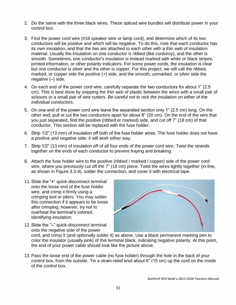
January 2011
The SeaPerch educational program was created by Harry Bohm and Vickie Jensen and published in their 1997 book "Build Your Own Underwater Robot and Other Wet Projects." The initial curriculum was developed by the Massachusetts Institute of Technology, and this version of the SeaPerch Construction Manual was provided under the Office of Naval Research National Naval Responsibility for Naval Engineering (NNRNE) Outreach
Version 2011-01AK Teachers Manual

SeaPerch ROV Build v.2011-01AK Teachers Manual
i
SeaPerch ROV Build v.2011-01AK Teachers Manual
i
Table of Contents
Introduction……………………………………………………………………………i SeaPerch ROV Program Overview
What is SeaPerch?
Program History
Original SeaPerch ROV Manual Development
Revised Standard SeaPerch Assembly Instructions
Three Individual Building Units
Recording Progress
Testing and Adjustments
Tools and Materials
Safety Overview…………………………………………………………………………….…iii Protective Eyewear
Materials Handling Safety
Safety While Using Hand Tools
Safety While Drilling
Safety While Soldering
Safety While Potting Motors for Thrusters
Safety with Electricity and Batteries
Unit 1 – Assembly of Subsystem One – The Vehicle Frame……………………1 Tools and Materials Needed
Time Needed to Complete Unit 1
Procedure 1.1 – Cut the Frame Parts
Procedure 1.2 – Drill the Drain Holes
Procedure 1.3 – Assemble the Vehicle Frame
Procedure1.4 – Assembly and Installation of the PVC Tube Floats
Procedure 1.5 – Attach the Thruster Mounts
Procedure 1.6 – Attach the Payload Net
Unit 2 – Assembly of Subsystem Two – The Thrusters…………………………11
Tools and Materials Needed
Time Needed to Complete Unit 2
Procedure 2.1 – Test the Motors and Mark their Terminals' Polarity
Procedure 2.2 – Seal the Motors So That Wax Cannot Get Inside
Procedure 2.3 – Drill Holes in the Thruster Housings
Procedure 2.4 – Connect the Tether Cable Wires to the Motors
Procedure 2.5 – Pot (Waterproof) the Motors with Wax
Procedure 2.5a – An Alternative to Potting Motors with Wax
Procedure 2.6 – Mount the Propellers on the Thruster Motors
Procedure 2.7 – Mount the Thrusters onto the Vehicle Frame
Procedure 2.8 – Waterproof and Secure the Tether Cable
Table of Contents
SeaPerch ROV Build v.2011-01AK Teachers Manual
ii
Unit 3 – Assembly of Subsystem Three – The Control Box……………………27
Tools and Materials Needed
Time Needed to Complete Unit 3
SeaPerch ROV Electrical Circuit Diagram
Procedure 3.1 – Locate the Parts for the Control Box
Procedure 3.2 – Prepare the Control Box
Procedure 3.3 – Assemble the Power Cord
Procedure 3.4 – Wire the Vertical Thruster Control Switch
Procedure 3.5 – Wire the Horizontal Thruster Control Switches
Procedure 3.6 – Finish the Control Box
Testing and Ballasting the ROV…………………………………………………..41 Time Needed to Complete Testing and Ballasting of the ROV
Initial Electrical Testing
Ballasting and Trimming the ROV
Using the SeaPerch ROV
Using the SeaPerch ROV…………………………………………………………..44 Safety Precautions
Environments Suitable for Using a SeaPerch ROV
Driving the SeaPerch ROV
Post-Run Cleaning and Maintenance of the ROV System
Appendix I – Troubleshooting Your SeaPerch ROV…………………………..47 Appendix II – How to Solder Like a Pro………………………………………….49 Appendix III – Installing a DB-9 Connector on the Tether Cable……………55 Appendix IV – Installation of an Underwater Video Camera………………....59 Appendix V - SeaPerch ROV Build Tool Kit……………………………………..61 Appendix VI – SeaPerch ROV Build Kit Components…………………………63

SeaPerch ROV Build v.2011-01AK Teachers Manual
i
SeaPerch ROV Program Overview What is SeaPerch? SeaPerch is an educational tool – a fun, hands-on learning activity and a curriculum that can be enjoyed by a wide range of students, ranging from late elementary school through high school and even introductory college programs. The curriculum is designed to meet many of the national learning standards identified by various United States agencies. Often applied at the middle school (or junior high school) level, SeaPerch is challenging, creative, and gets kids excited about science and technology. The SeaPerch program is sponsored through the National Naval Responsibility for Naval Engineering (NNRNE) Outreach effort, with the goal of helping to inspire the next generation of naval architects and marine, ocean, and naval engineers.
A SeaPerch is an underwater robot known as a “remotely operated vehicle,” or “ROV.” Students learn best by doing, and during the SeaPerch project they will completely assemble an inexpensive yet functional ROV, test it, and then operate it underwater. The experience will enable them to explore science and technology both in the classroom and in a pool or, for some, in natural marine environments. The ROVs are built from kits comprised of low-cost, easily-obtained components. Students often work in small teams to assemble their vehicles, usually over a period of several weeks. From the classroom activities during SeaPerch construction through in-water application of the ROV, they will have opportunities to learn about various subjects including mathematics, robotics, biology, oceanography, physics, and history, as well as valuable problem solving and teamwork skills.
The SeaPerch program is structured to provide free training to help teachers more effectively lead students through the variety of interdisciplinary activities involved. Within one project, a number of concepts required for their grade level can be efficiently addressed with the further benefit of exposing the students to additional concepts that may not otherwise be easily covered with their standard curriculum. Mentors from government and industry are often available to support and reinforce the lessons as well as to assist with the SeaPerch construction and application activities in the classroom.
Program History The SeaPerch Remotely Operated Vehicle (ROV) educational program was inspired by the 1997 book, Build Your Own Underwater Robot and Other Wet Projects (ISBN 0-9681610-6), by Harry Bohm and Vickie Jensen. In 1997, Dr. Tom Consi introduced SeaPerch to the Ocean Engineering program at the Massachusetts Institute of Technology (MIT), in order to interest more students in majoring in Ocean Engineering. Realizing the potential of SeaPerch to reach younger students, the MIT Sea Grant (MITSG) College Program created the SeaPerch initiative in 2003, sponsored by the Office of Naval Research. Dr. Chryssostomos Chryssostomidis, MITSG Director, and Brandy Wilbur, Educational Coordinator, were responsible for the effort at MIT Sea Grant. In late 2007, the Office of Naval Research (ONR) tasked the Society of Naval Architects and Marine Engineers (SNAME) to research ways to expand and enhance the SeaPerch initiative as part of the ONR National Naval Responsibility for Naval Engineering Outreach effort.
Original SeaPerch ROV Manual Development The SeaPerch Construction Manual was originally developed by MITSG, who modified the instructions for building a SeaPerch from those found in Build Your Own Underwater Robot and Other Wet Projects so that the ROV would be simpler and cheaper to build in the classroom. MITSG created a
SeaPerch ROV Build v.2011-01AK Teachers Manual
ii
three-unit manual with detailed, step-by-step instructions and a complete list of needed components and tools. The MITSG SeaPerch manual has been revised several times in recent years as new vehicle components or updated assembly methods were implemented for the program.
Updated Information in This Version of the SeaPerch Manual Revised Standard SeaPerch Assembly Instructions This manual revision builds upon the extensive work of the MITSG developers by utilizing the experience gained through years of SeaPerch program use by educators around the country, incorporating the latest recommended construction techniques, and providing additional information to help teachers and students build and use SeaPerch ROVs. While much of this revision’s technical content is aligned with the instructions found in previous versions, its revised graphics and content adjustments are designed to provide additional detail for the more complex construction techniques.
Three Individual Building Units The manual contains three building units for the frame, the thrusters, and the control box. They may be used as a single manual, as assembled here, or they can be removed from this manual and used separately. In either case, the three unit manuals should always be used in order. Unit 1 is a good confidence-builder for the students who have had little experience working with tools, and it gets the project going quickly. They will measure, cut, and drill pipe and fittings and then assemble the parts with quick results, as the work in Unit 1 provides a recognizable ROV frame after just a few class periods. Unit 2 then introduces basic wiring and soldering skills by working with the motors for the thrusters. These skills are important for them to have when building the control box in Unit 3. Finally, Unit 3 involves the students in more advanced wiring and soldering activities and provides an opportunity for them to work with a variety of tools and components used in electrical technologies.
Recording Progress Checklist-style boxes next to each numbered step in a manual are sometimes included so students may write their initials confirming proper completion of each step as they progress through the project. Keeping track in this way is important to avoid accidentally skipping steps, but it also greatly helps the teacher and classroom volunteers (as well as other team members, if working in teams), to know how far the student or team has progressed in the building process. This manual does not use checkboxes; simply have students write their initials next to each step as it is completed.
Testing and Adjustments The last steps in the SeaPerch ROV construction process are to conduct some basic electrical tests prior to connecting the battery and performing some simple vehicle checks and adjustments prior to its first operational use. The initial testing in the classroom or lab should help in finding any lingering wiring or thruster-related issues and the checks recommended before operational use should help to ensure a successful operational experience for all students.
Tools and Materials Each procedure in this manual identifies the needed components and tools only generically rather than giving specific descriptions or specifications for each item. Detailed parts, tools, and materials lists are maintained as separate documents for use in procuring the items needed to build the ROVs. This approach allows these assembly instructions to remain applicable even when the specifics of individual components change, such as when a slightly different “12 Volt DC Motor” is used or when a
SeaPerch ROV Build v.2011-01AK Teachers Manual
iii
similar component must be substituted due to availability or cost issues. SeaPerch ROVs are often built by a team of two or three students. For efficiency during the build process, each team should have its own set of basic tools, including a screwdriver, flush-type wire cutter, needle-nose pliers, wire stripper, and soldering iron. Tools such as standard pliers, cable jacket strippers, pipe cutters, drills, and others that are not used on a daily basis can be easily shared among a number of teams. A key aspect of planning for classroom tools is to obtain enough to ensure that students do not need to stop long during the build process to wait for availability of needed tools.
Safety During the Build Protective Eyewear Students, teachers, and classroom helpers should wear protective eyewear at all times when building SeaPerch ROVs. Although some procedures do not usually involve significant eye hazards, the students often work close to others, who at any time may be performing more potentially hazardous steps. Activities such as soldering, cutting, drilling, applying adhesives, and potting thrusters can easily cause materials or parts of broken tools to fly significant distances. Below are some examples:
Soldering: Solder contains rosin flux in its core to help clean the electrical connections, which helps the solder to adhere to the metal properly. Small amounts of flux can occasionally pop out of the melting solder and sometimes travel far enough to reach the eye of the person soldering, or even someone nearby. Protective eyewear is essential for everyone in the area.
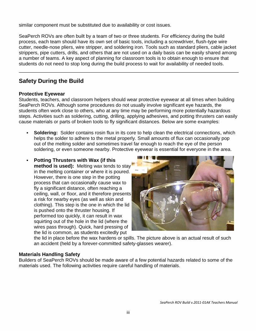
Potting Thrusters with Wax (if this method is used): Melting wax tends to stay in the melting container or where it is poured. However, there is one step in the potting process that can occasionally cause wax to fly a significant distance, often reaching a ceiling, wall, or floor, and it therefore presents a risk for nearby eyes (as well as skin and clothing). This step is the one in which the lid is pushed onto the thruster housing. If performed too quickly, it can result in wax squirting out of the hole in the lid (where the wires pass through). Quick, hard pressing of the lid is common, as students excitedly put the lid in place before the wax hardens or spills. The picture above is an actual result of such an accident (held by a forever-committed safety-glasses wearer).
Materials Handling Safety Builders of SeaPerch ROVs should be made aware of a few potential hazards related to some of the materials used. The following activities require careful handling of materials.
SeaPerch ROV Build v.2011-01AK Teachers Manual
iv
Soldering: Many common types of solder contain lead, tin and sometimes other metals. Solder should never be placed in one’s mouth, and hands should always be washed after working with solder. Breathing the smoke from the melting flux (from inside the solder) should be avoided.
Potting Wax (if used): Bowl ring wax is made from “petrolatum” – basically the same type of material that, when more refined, becomes common petroleum jelly. It is safe to handle when cooled, but quite sticky, and difficult to remove if it solidifies on clothing. Hands should be washed with warm water and soap after handling the wax. Obviously, it must not be ingested. Wearing eye protection, as noted earlier, is essential.
Adhesives (if used): Adhesives, particularly two-part epoxy, “super glue” type adhesives, and PVC primer and cement (some versions of SeaPerch ROVs don't use all of these types) can present hazards to skin as well as eyes. Wearing eye protection and gloves is recommended when working with any adhesives, and hands should always be washed after working with such materials.
Protection of Our Environment: All waste or scrap materials from the SeaPerch ROV construction process should be disposed of properly, in accordance with manufacturers’ recommendations and school policies. Recycling of usable excess materials and disassembled vehicles is encouraged for environmental protection and cost avoidance considerations. Most of the ROV components can be re-used in building future vehicles or as spare parts.
Safety While Using Hand Tools Using Hand Tools Hand tools such as screwdrivers, pliers, and wire cutters can be used safely when operated as intended. Examples of activities to avoid are below:
Screwdrivers: Screwdrivers should not be used to pry or make holes. Care should be exercised while inserting or removing screws to avoid having the screwdriver tip slip off of the screw head and poke into a body part or damage a table top. The size of the screwdriver tip should be appropriate for the size of the screw.
Wire Cutters: Nothing should be cut with small wire cutters other than copper wire or plastic tie wraps. Never cut pipe or metal fasteners, which could ruin the cutting edges. Be careful when handling wire cutters to avoid being cut or poked by their sharp cutting edges or tips.
Needle-Nose Pliers: Small, thin, needle-nose pliers should be used only to help place wires onto switch or motor terminals, as their jaws can bend or break if used for tightening tie wraps or any prying activity. Large needle-nose pliers or standard club-nose pliers are better for tightening tie wraps. Needle-nose pliers should also not be used for tightening the retaining nuts on control box switches, as the jaws are not parallel like the edges of a nut, so they can easily slip off. Use club-nose pliers or a small wrench instead to tighten the nuts on switches.
PVC Pipe Cutters: The blades on typical PVC pipe cutters can be damaged easily if used to cut anything except PVC pipe, or if used incorrectly. When squeezing the tool to cut pipe, work slowly so that the blade has time to move through the material. Do not twist the tool, and always keep fingers away from the sharp blade. Store the tool in its closed position.
SeaPerch ROV Build v.2011-01AK Teachers Manual
v
Safety While Drilling Drilling is perhaps the most potentially hazardous activity involved in the SeaPerch project. Some important safety considerations are as follows:
Get Permission to Use Power Tools: Always get the teacher’s permission and adult supervision before using a drill or other power tool.
Installing and Removing Drill Bits: Install and remove drill bits from the chuck of a drill motor or drill press manually, not by energizing the drill motor to spin the chuck closed. Make sure that the bit is inserted straight into the chuck and that it is tight in the chuck before use; spin it briefly to check before drilling.
Holding Objects Being Drilled: Never try to hold an object being drilled in your hand alone. Instead, it should be always be either held in a vise (or clamp), firmly held down by hand onto a solid surface (if that surface will not be subjected to possible damage during the drilling process), or attached firmly to an object that can be safely held by hand. This keeps the object steady, prevents it from spinning and hurting your hand if the drill bit should bind, and keeps your fingers away from the bit while drilling. Never place a body part in the path of a drill bit. Always think about what is behind the object being drilled (particularly body parts and tabletops!). If using a drill press, make sure that the object is held firmly and fingers are not near the drill bit.
Safety While Soldering (refer to Appendix II – How to Solder Like a Pro for tips) Soldering Uses High Heat: All soldering involves a very hot soldering iron as well as
temporarily-hot electrical connections which take a few moments to cool after soldering. Do not touch the tip area of a soldering iron, even when it appears to be off or unplugged, as it does not look different when it is hot compared to when it is cold and it can remain hot for 10 minutes or more after use. Connections should be allowed to cool after soldering before they are moved or touched. As noted earlier, always wear eye protection, even when just in the same area as someone who is soldering.
Keep the Soldering Iron in Its Holder When Not in Use: Great care should be taken to place the soldering iron back into its holder whenever it is not in use for soldering. Never just set it down on a tabletop, where it could burn anything it touches.
Safety While Potting Motors for Thrusters SeaPerch ROV thrusters are assembled by potting small electric motors in wax. The following safety issues should be reviewed with everyone involved in the potting process:
Melting Wax: The standard SeaPerch wax-melting approach is to warm “toilet bowl ring” wax in a heated pot or a metal container placed in a hot water bath, usually employing an electric hotplate to heat the water (and wax). It is important to always monitor the temperature of the wax or use a water bath (and NOT let all of the water evaporate - keep adding water to maintain it at about ½” to 1” deep). Otherwise, the wax can get EXTREMELY hot, even hot enough to melt the plastic thruster housings. Fortunately, bowl ring wax has a relatively low melting temperature, but it must still be heated to about 150 degrees Fahrenheit (F) for proper pouring. Although its flash point is over 500 degrees F, manufacturers usually recommend not exceeding 200 degrees F, so you should try to keep the wax at about 180 degrees F or below (using a thermometer is best, as temperature control knob markings may be inaccurate). If the wax is allowed to get too hot, skin burns are possible. In case of a burn, quickly rinse the area
SeaPerch ROV Build v.2011-01AK Teachers Manual
vi
with plenty of cold water and seek medical attention. Care should be taken to prevent getting the hot wax onto skin or clothing. Wearing a protective smock or apron and gloves is recommended. Pour the wax slowly and carefully to prevent spills and potential burns. During the final step of thruster potting when the lid is placed onto the thruster housing, melted wax can squirt out of the small hole in the lid where the wires pass through. If the lid is pressed quickly into place, wax can even squirt as high as the ceiling or onto nearby walls and people. Placing a paper towel over the lid and pressing slowly is recommended to avoid the wax-squirting problem. Protect nearby walls and floor areas with paper or tarps. Obviously, everyone in the area should be wearing eye protection.
Safety with Electricity and Batteries The low-voltage (12 volts, direct current (DC)) battery power source used with SeaPerch ROVs is relatively safe and well-proven in students’ hands. However, they should be cautioned about potential problems from short-circuits as well as electrical safety issues in general.
Battery Short-Circuit Hazard: Although the battery can be used quite safely when it is
connected properly to the ROV, it can be damaged, cause wires to melt, or even start a fire if its positive and negative terminals are connected directly together. That is called a “short circuit,” and it will allow the battery to essentially discharge all of its stored energy at once. Besides resulting in sparks when such an improper connection is made, the wire or metal object shorting across the terminal will immediately become extremely hot and may even melt. That could obviously cause burns or ignite an object in contact with the shorting material. Never connect anything between the battery terminals except an appropriate electrical “load” such as the ROV circuitry, through its fused power cord. Be careful to keep the battery terminals covered or away from all wires and metal objects when not in use. Do not connect the ROV circuitry or components to the battery until instructed to do so.
Avoid Creating Other Short Circuits During ROV Construction: When wiring circuits or conducting tests, take care to avoid unintended connections or accidental short circuits. While handling partially or fully completed circuits, ensure that wires do not move and touch together where they should not. Always check the circuitry carefully and conduct the recommended tests before connecting the battery.
General Electrical Safety: When working with electrical circuits with power applied, do not allow any body parts to “become part of the circuit.” In other words, do not touch both the positive and negative terminals of a battery with your hands or touch a battery terminal with one hand and part of the circuitry with the other. Make sure that all switches are in their off positions while connecting or disconnecting the battery, and connect just one power wire at a time.
SeaPerch Remotely Operated Vehicle
Assembly of Subsystem One The Vehicle Frame
January 2011
Version 2011-01AK
SeaPerch ROV Build v.2011-01AK Teachers Manual
2
Assembly of Subsystem One The Vehicle Frame Tools and Materials Needed
Time Needed to Complete Unit 1 Unit 1 usually requires at least 4 to 5 hours to complete, if the required raw materials and components are already sorted into kits for each ROV. When materials must be cut from standard lengths of pipe, rolls of payload netting, etc., plan on up to an additional hour to complete the ROV frame. Have some extra ½” PVC pipe on hand, as pipe-cutting errors sometimes occur.
Typical Allocation of Class Periods: For standard class periods of approximately 50 minutes each, including any necessary clean-up time, plan for at least five periods to complete this unit.
1 period to cut the PVC pipe and drill the holes in the PVC elbows. 2 periods to assemble the frame and attach the payload and capture nets. 2 periods to assemble and attach the floats and to drill holes and attach the thruster mounts.
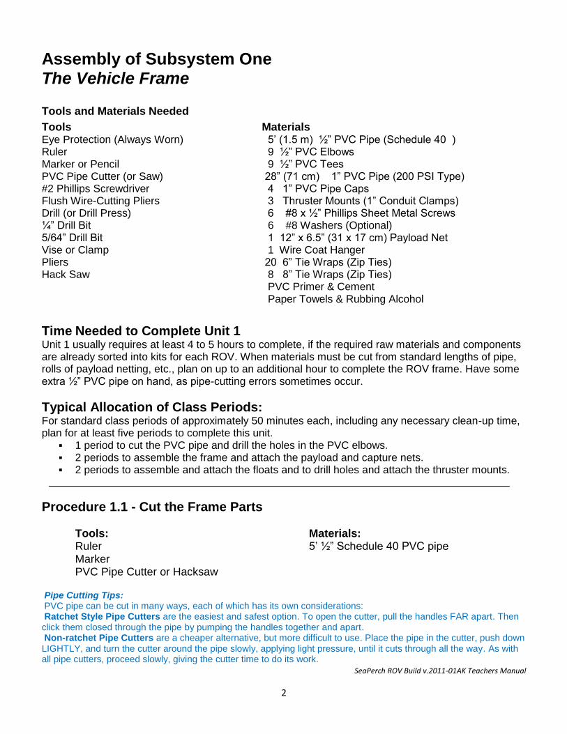
Procedure 1.1 - Cut the Frame Parts Tools: Materials: Ruler 5’ ½” Schedule 40 PVC pipe Marker PVC Pipe Cutter or Hacksaw Pipe Cutting Tips: PVC pipe can be cut in many ways, each of which has its own considerations: Ratchet Style Pipe Cutters are the easiest and safest option. To open the cutter, pull the handles FAR apart. Then click them closed through the pipe by pumping the handles together and apart. Non-ratchet Pipe Cutters are a cheaper alternative, but more difficult to use. Place the pipe in the cutter, push down LIGHTLY, and turn the cutter around the pipe slowly, applying light pressure, until it cuts through all the way. As with all pipe cutters, proceed slowly, giving the cutter time to do its work.
Tools Materials Eye Protection (Always Worn) Ruler Marker or Pencil PVC Pipe Cutter (or Saw) #2 Phillips Screwdriver Flush Wire-Cutting Pliers Drill (or Drill Press) ¼” Drill Bit 5/64” Drill Bit Vise or Clamp Pliers Hack Saw
5’ (1.5 m) ½” PVC Pipe (Schedule 40 ) 9 ½” PVC Elbows 9 ½” PVC Tees 28” (71 cm) 1” PVC Pipe (200 PSI Type) 4 1” PVC Pipe Caps 3 Thruster Mounts (1” Conduit Clamps) 6 #8 x ½” Phillips Sheet Metal Screws 6 #8 Washers (Optional) 1 12” x 6.5” (31 x 17 cm) Payload Net 1 Wire Coat Hanger 20 6” Tie Wraps (Zip Ties) 8 8” Tie Wraps (Zip Ties) PVC Primer & Cement Paper Towels & Rubbing Alcohol
SeaPerch ROV Build v.2011-01AK Teachers Manual
3
Hack Saws and other hand saws can cut through PVC, but are the most labor intensive option. Band Saws are large pieces of shop equipment, and they can be very dangerous. Make sure to get your teacher’s permission and supervision before using one.
Construction Steps:
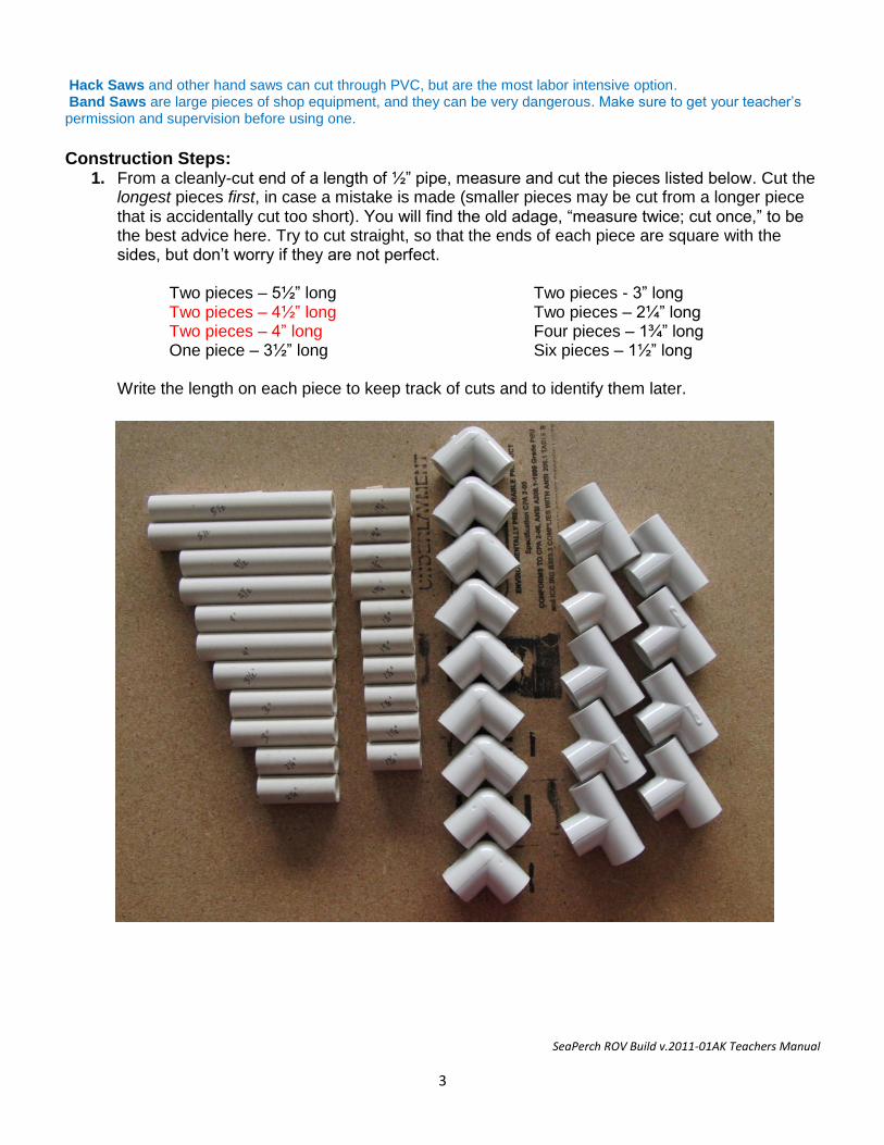
1. From a cleanly-cut end of a length of ½” pipe, measure and cut the pieces listed below. Cut the longest pieces first, in case a mistake is made (smaller pieces may be cut from a longer piece that is accidentally cut too short). You will find the old adage, “measure twice; cut once,” to be the best advice here. Try to cut straight, so that the ends of each piece are square with the sides, but don’t worry if they are not perfect.
Two pieces – 5½” long Two pieces - 3” long Two pieces – 4½” long Two pieces – 2¼” long Two pieces – 4” long Four pieces – 1¾” long One piece – 3½” long Six pieces – 1½” long
Write the length on each piece to keep track of cuts and to identify them later.
SeaPerch ROV Build v.2011-01AK Teachers Manual
4
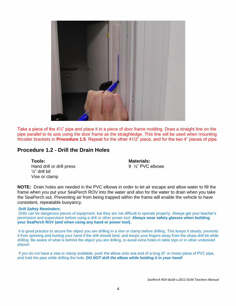
Take a piece of the 4½” pipe and place it in a piece of door frame molding. Draw a straight line on the pipe parallel to its axis using the door frame as the straightedge. This line will be used when mounting thruster brackets in Procedure 1.5. Repeat for the other 41/2” piece, and for the two 4” pieces of pipe.
Procedure 1.2 - Drill the Drain Holes Tools: Materials: Hand drill or drill press 9 ½” PVC elbows ¼” drill bit Vise or clamp
NOTE: Drain holes are needed in the PVC elbows in order to let air escape and allow water to fill the frame when you put your SeaPerch ROV into the water and also for the water to drain when you take the SeaPerch out. Preventing air from being trapped within the frame will enable the vehicle to have consistent, repeatable buoyancy.
Drill Safety Reminders: Drills can be dangerous pieces of equipment, but they are not difficult to operate properly. Always get your teacher’s permission and supervision before using a drill or other power tool. Always wear safety glasses when building your SeaPerch ROV (and when using any hand or power tool). It is good practice to secure the object you are drilling in a vise or clamp before drilling. This keeps it steady, prevents it from spinning and hurting your hand if the drill should bind, and keeps your fingers away from the sharp drill bit while drilling. Be aware of what is behind the object you are drilling, to avoid extra holes in table tops or in other undesired places! If you do not have a vise or clamp available, push the elbow onto one end of a long (5” or more) piece of PVC pipe, and hold the pipe while drilling the hole. DO NOT drill the elbow while holding it in your hand!
SeaPerch ROV Build v.2011-01AK Teachers Manual
5
5.5”
5.5
”
4.5”
4.5”
3”
3”
4”
4”
1.5”
1.5”
1.5”
2.25”
2.25”
1.75”
Front
Construction Steps: 1. Inspect the PVC elbows to see if they have ¼” holes drilled in them (such as from a previous
use). If they all have ¼” holes, skip to Procedure 1.3.
2. Secure a PVC elbow in a vise or clamp.
3. Place the ¼" drill bit in the drill (or drill press), and drill a hole in the corner of the elbow. Drilling from the interior of the elbow outward works best, as the bit can easily slip off of the rounded exterior of the elbow.
4. Repeat Steps 2 and 3 for other PVC elbows that don’t have the ¼” holes.
Procedure 1.3 – Assemble the Vehicle Frame Tools: Materials: Rubber-faced hammer 23 Cut Pieces of pipe from Procedure 1.1 9 ½” PVC elbows from Procedure 1.2 9 ½” PVC Tees
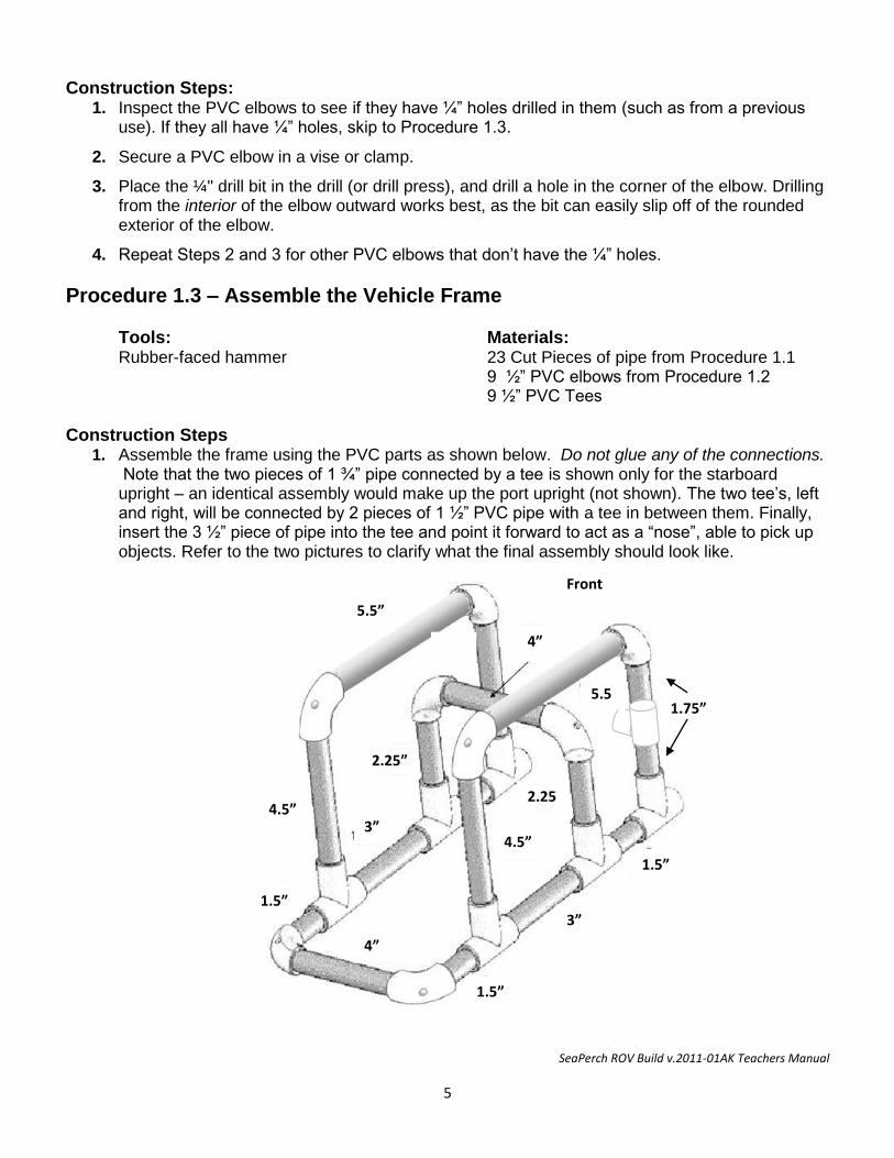
Construction Steps 1. Assemble the frame using the PVC parts as shown below. Do not glue any of the connections.
Note that the two pieces of 1 ¾” pipe connected by a tee is shown only for the starboard upright – an identical assembly would make up the port upright (not shown). The two tee’s, left and right, will be connected by 2 pieces of 1 ½” PVC pipe with a tee in between them. Finally, insert the 3 ½” piece of pipe into the tee and point it forward to act as a “nose”, able to pick up objects. Refer to the two pictures to clarify what the final assembly should look like.
SeaPerch ROV Build v.2011-01AK Teachers Manual
6
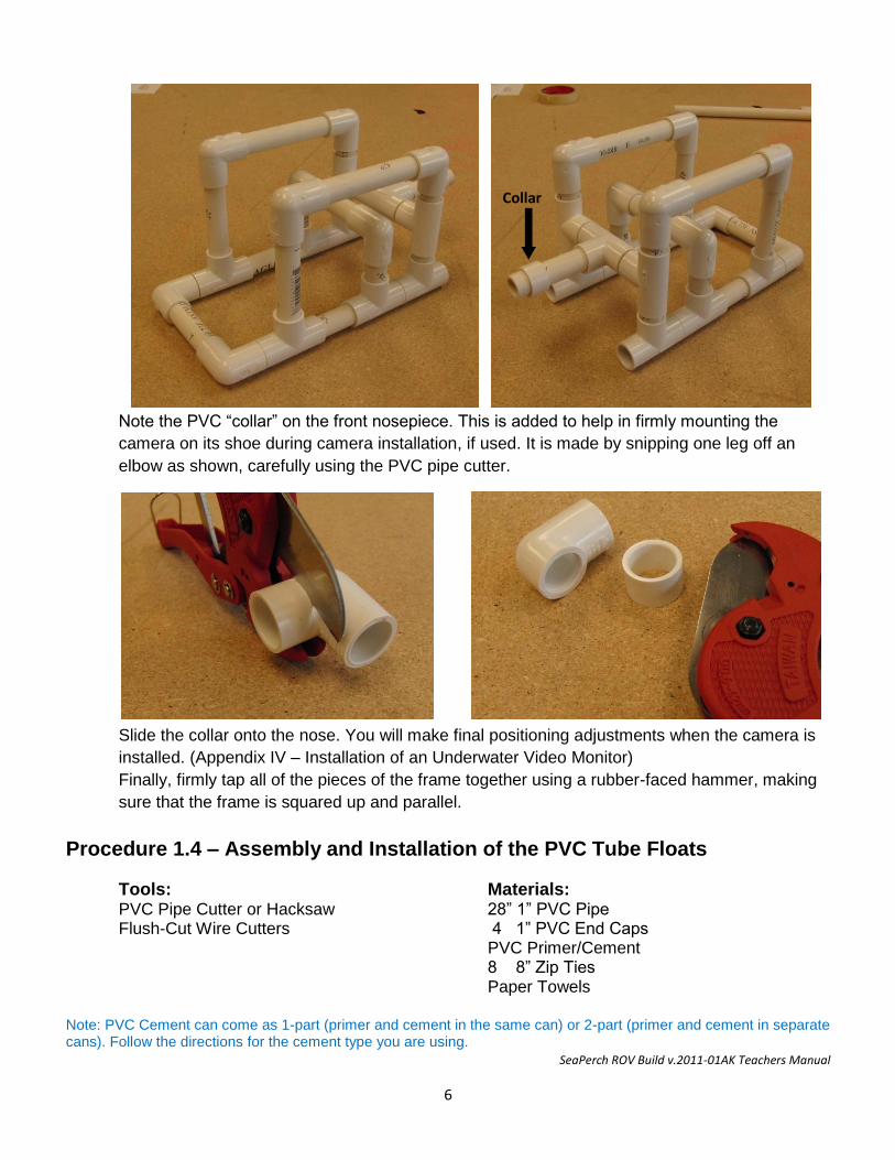
Note the PVC “collar” on the front nosepiece. This is added to help in firmly mounting the
camera on its shoe during camera installation, if used. It is made by snipping one leg off an
elbow as shown, carefully using the PVC pipe cutter.
Slide the collar onto the nose. You will make final positioning adjustments when the camera is
installed. (Appendix IV – Installation of an Underwater Video Monitor)
Finally, firmly tap all of the pieces of the frame together using a rubber-faced hammer, making
sure that the frame is squared up and parallel.
Procedure 1.4 – Assembly and Installation of the PVC Tube Floats
Tools: Materials: PVC Pipe Cutter or Hacksaw 28” 1” PVC Pipe Flush-Cut Wire Cutters 4 1” PVC End Caps PVC Primer/Cement 8 8” Zip Ties Paper Towels
Note: PVC Cement can come as 1-part (primer and cement in the same can) or 2-part (primer and cement in separate cans). Follow the directions for the cement type you are using.
Collar
SeaPerch ROV Build v.2011-01AK Teachers Manual
7
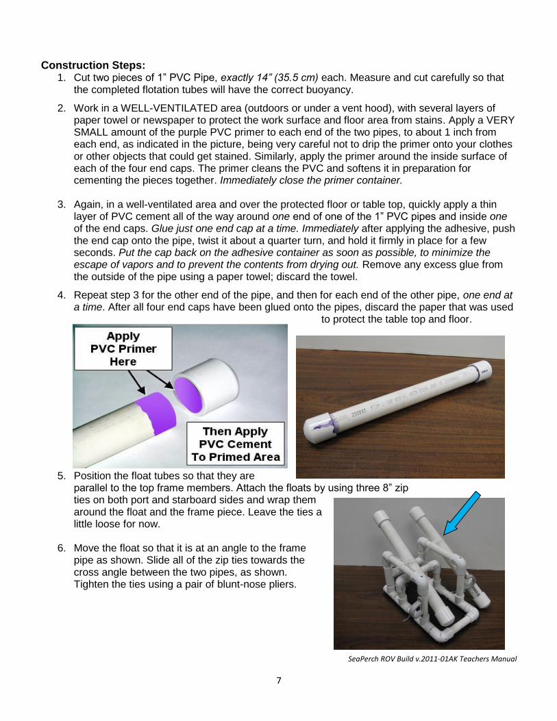
Construction Steps: 1. Cut two pieces of 1” PVC Pipe, exactly 14” (35.5 cm) each. Measure and cut carefully so that
the completed flotation tubes will have the correct buoyancy.
2. Work in a WELL-VENTILATED area (outdoors or under a vent hood), with several layers of paper towel or newspaper to protect the work surface and floor area from stains. Apply a VERY SMALL amount of the purple PVC primer to each end of the two pipes, to about 1 inch from each end, as indicated in the picture, being very careful not to drip the primer onto your clothes or other objects that could get stained. Similarly, apply the primer around the inside surface of each of the four end caps. The primer cleans the PVC and softens it in preparation for cementing the pieces together. Immediately close the primer container.
3. Again, in a well-ventilated area and over the protected floor or table top, quickly apply a thin layer of PVC cement all of the way around one end of one of the 1” PVC pipes and inside one of the end caps. Glue just one end cap at a time. Immediately after applying the adhesive, push the end cap onto the pipe, twist it about a quarter turn, and hold it firmly in place for a few seconds. Put the cap back on the adhesive container as soon as possible, to minimize the escape of vapors and to prevent the contents from drying out. Remove any excess glue from the outside of the pipe using a paper towel; discard the towel.
4. Repeat step 3 for the other end of the pipe, and then for each end of the other pipe, one end at a time. After all four end caps have been glued onto the pipes, discard the paper that was used
to protect the table top and floor.
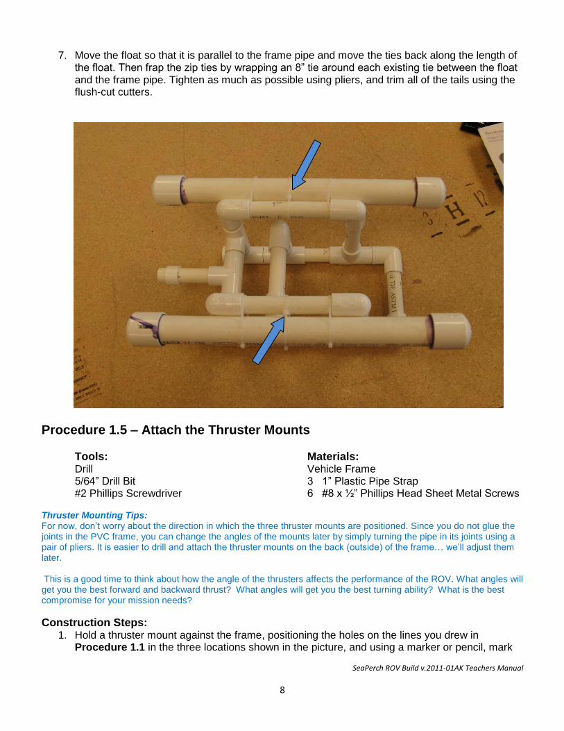
5. Position the float tubes so that they are parallel to the top frame members. Attach the floats by using three 8” zip ties on both port and starboard sides and wrap them around the float and the frame piece. Leave the ties a little loose for now.
6. Move the float so that it is at an angle to the frame
pipe as shown. Slide all of the zip ties towards the cross angle between the two pipes, as shown. Tighten the ties using a pair of blunt-nose pliers.
SeaPerch ROV Build v.2011-01AK Teachers Manual
8
7. Move the float so that it is parallel to the frame pipe and move the ties back along the length of the float. Then frap the zip ties by wrapping an 8” tie around each existing tie between the float and the frame pipe. Tighten as much as possible using pliers, and trim all of the tails using the flush-cut cutters.
Procedure 1.5 – Attach the Thruster Mounts Tools: Materials: Drill Vehicle Frame 5/64” Drill Bit 3 1” Plastic Pipe Strap #2 Phillips Screwdriver 6 #8 x ½” Phillips Head Sheet Metal Screws Thruster Mounting Tips: For now, don’t worry about the direction in which the three thruster mounts are positioned. Since you do not glue the joints in the PVC frame, you can change the angles of the mounts later by simply turning the pipe in its joints using a pair of pliers. It is easier to drill and attach the thruster mounts on the back (outside) of the frame… we’ll adjust them later. This is a good time to think about how the angle of the thrusters affects the performance of the ROV. What angles will get you the best forward and backward thrust? What angles will get you the best turning ability? What is the best compromise for your mission needs?
Construction Steps: 1. Hold a thruster mount against the frame, positioning the holes on the lines you drew in
Procedure 1.1 in the three locations shown in the picture, and using a marker or pencil, mark
SeaPerch ROV Build v.2011-01AK Teachers Manual
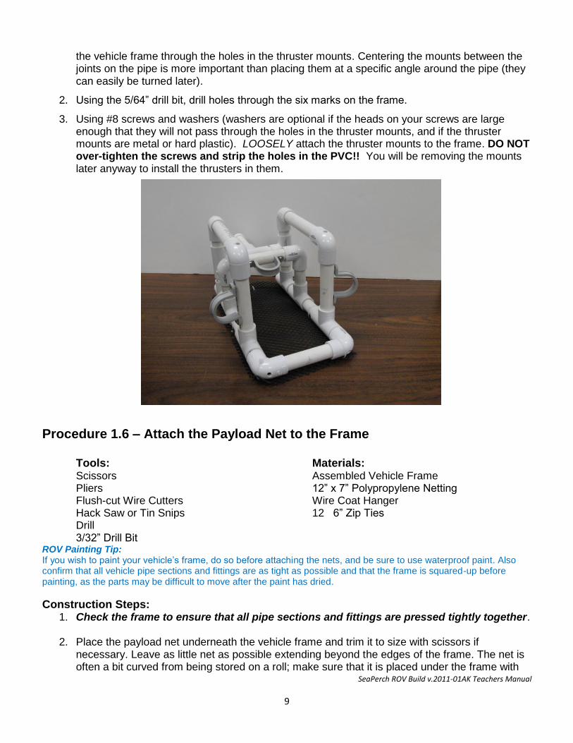
9
the vehicle frame through the holes in the thruster mounts. Centering the mounts between the joints on the pipe is more important than placing them at a specific angle around the pipe (they can easily be turned later).
2. Using the 5/64” drill bit, drill holes through the six marks on the frame.
3. Using #8 screws and washers (washers are optional if the heads on your screws are large enough that they will not pass through the holes in the thruster mounts, and if the thruster mounts are metal or hard plastic). LOOSELY attach the thruster mounts to the frame. DO NOT over-tighten the screws and strip the holes in the PVC!! You will be removing the mounts later anyway to install the thrusters in them.
Procedure 1.6 – Attach the Payload Net to the Frame Tools: Materials: Scissors Assembled Vehicle Frame Pliers 12” x 7” Polypropylene Netting Flush-cut Wire Cutters Wire Coat Hanger Hack Saw or Tin Snips 12 6” Zip Ties Drill 3/32” Drill Bit ROV Painting Tip: If you wish to paint your vehicle’s frame, do so before attaching the nets, and be sure to use waterproof paint. Also confirm that all vehicle pipe sections and fittings are as tight as possible and that the frame is squared-up before painting, as the parts may be difficult to move after the paint has dried.
Construction Steps: 1. Check the frame to ensure that all pipe sections and fittings are pressed tightly together.
2. Place the payload net underneath the vehicle frame and trim it to size with scissors if
necessary. Leave as little net as possible extending beyond the edges of the frame. The net is often a bit curved from being stored on a roll; make sure that it is placed under the frame with
SeaPerch ROV Build v.2011-01AK Teachers Manual
10
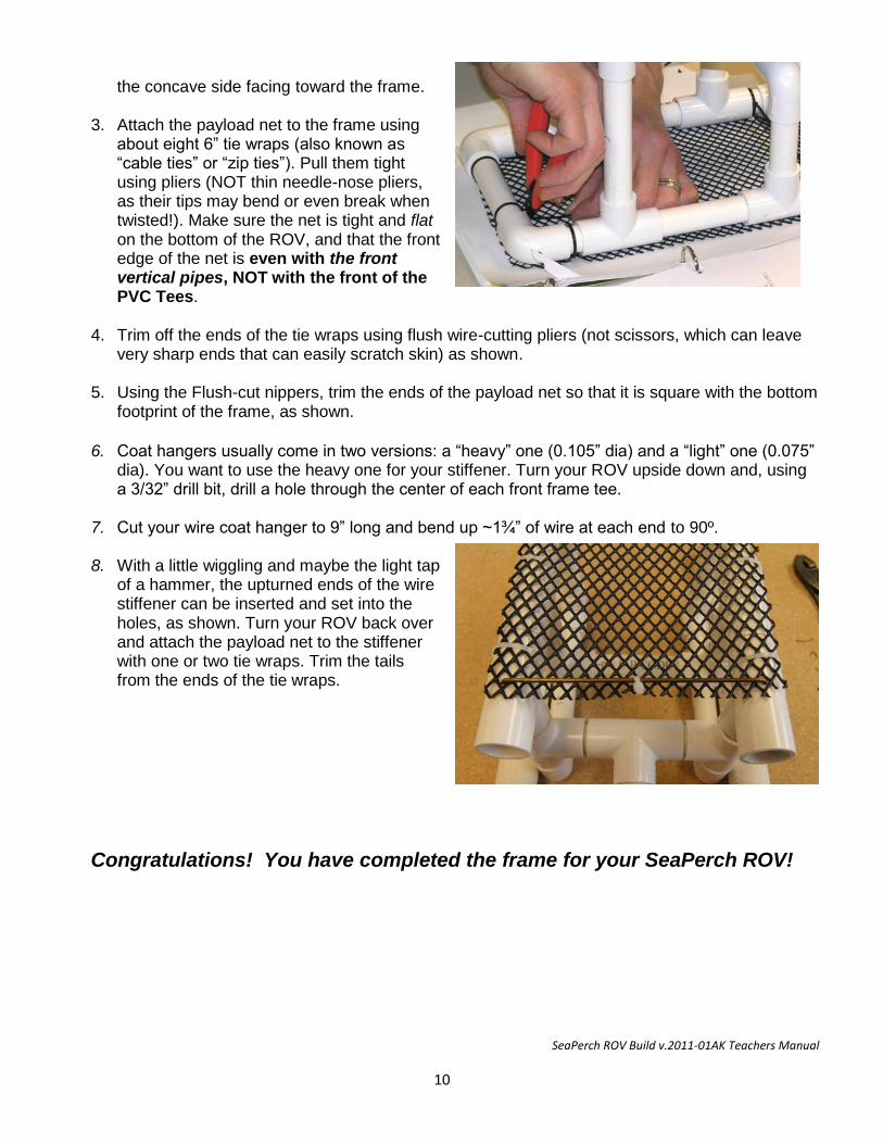
the concave side facing toward the frame.
3. Attach the payload net to the frame using about eight 6” tie wraps (also known as “cable ties” or “zip ties”). Pull them tight using pliers (NOT thin needle-nose pliers, as their tips may bend or even break when twisted!). Make sure the net is tight and flat on the bottom of the ROV, and that the front edge of the net is even with the front vertical pipes, NOT with the front of the PVC Tees.
4. Trim off the ends of the tie wraps using flush wire-cutting pliers (not scissors, which can leave very sharp ends that can easily scratch skin) as shown.
5. Using the Flush-cut nippers, trim the ends of the payload net so that it is square with the bottom footprint of the frame, as shown.
6. Coat hangers usually come in two versions: a “heavy” one (0.105” dia) and a “light” one (0.075” dia). You want to use the heavy one for your stiffener. Turn your ROV upside down and, using a 3/32” drill bit, drill a hole through the center of each front frame tee.
7. Cut your wire coat hanger to 9” long and bend up ~1¾” of wire at each end to 90º.
8. With a little wiggling and maybe the light tap
of a hammer, the upturned ends of the wire stiffener can be inserted and set into the holes, as shown. Turn your ROV back over and attach the payload net to the stiffener with one or two tie wraps. Trim the tails from the ends of the tie wraps.
Congratulations! You have completed the frame for your SeaPerch ROV!
SeaPerch ROV Build v.2011-01AK Teachers Manual
11
SeaPerch Remotely Operated Vehicle
Assembly of Subsystem Two The Thrusters
January 2011
Version 2011-01AK
SeaPerch ROV Build v.2011-01AK Teachers Manual
12
Tools and Materials Needed Tools: Materials: Eye Protection 40’ Tether Cable (CAT 5 or 5e) Drill 3 Plastic Vials 5/64” Drill Bit 3 12VDC Motors Small Electric Hotplate 3 Propellers Metal Cup for Wax 3 1/8” x ½” Roll Pins Pliers 3/4 Wax Bowl Ring Wire Stripper 16-24 ga. 1” Butyl Rubber Tape Flush-cut Wire Cutters 24” #22 Stranded Red Hook-up Wire Locking Long-Nose Pliers 24” #22 Stranded Black Hook-up Wire Soldering Iron and Rosin Core Solder 1 12VDC Battery #2 Phillips Screwdriver 12 Zip Ties 3/32” Drill Bit Alternative Potting Procedure Wooden Stirrer Marine Potting Epoxy
Total Construction Time: Unit 2 usually requires at least 6 to 7 hours to complete. More time should be allowed if potting thrusters for a large number of ROVs.
Typical Allocation of Class Periods: For standard class periods of approximately 50 minutes each, including any necessary clean-up time, plan for at least 5-6 periods to complete this unit. 1 periods to test, mark, and wrap the motors for potting. 2 periods to solder wires to the motors and prepare thruster housings. 1 period to pot the motors (several periods for a large number of ROVs). 1 periods to mount the propellers onto the motor shafts (more for many ROVs, with shared tools) and attach the thrusters and tether cable. Note: Before starting the potting procedure, make a potting holder to hold motors in place by drilling several 5/64” holes about 2” apart and 1” deep in a block of wood, for example a short piece of 2” x 4” building lumber. This hole will accept the shaft of the DC motors during the potting procedure(s).
Procedure 2.1 - Test the Motors and Mark the Terminal Polarity Tools: Materials: Marker 3 12VDC Motors Wire Stripper 2 24” #22 Hook-up Wire, One Red & One Black 12 VDC Battery
Electrical Tape
WARNING - TO AVOID ELECTRIC SHOCK AND POTENTIAL BURNS: - DO NOT touch exposed wires when making connections to battery terminals. - DO NOT touch the battery terminals with ANY metal object, especially tools! - DO NOT CONNECT WIRE OR METAL FROM ONE BATTERY TERMINAL TO THE OTHER!
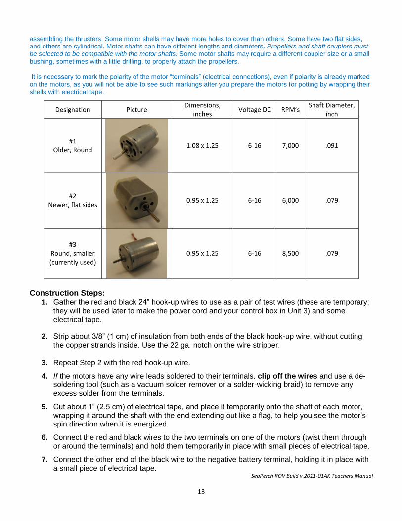
Note: Small 12-volt DC motors of various types are available for SeaPerch kits, such as those shown below. Some may come with wire leads already attached. In that case, the wires must be removed prior to testing the motors and
SeaPerch ROV Build v.2011-01AK Teachers Manual
13
assembling the thrusters. Some motor shells may have more holes to cover than others. Some have two flat sides, and others are cylindrical. Motor shafts can have different lengths and diameters. Propellers and shaft couplers must be selected to be compatible with the motor shafts. Some motor shafts may require a different coupler size or a small bushing, sometimes with a little drilling, to properly attach the propellers. It is necessary to mark the polarity of the motor “terminals” (electrical connections), even if polarity is already marked on the motors, as you will not be able to see such markings after you prepare the motors for potting by wrapping their shells with electrical tape.
Construction Steps:
1. Gather the red and black 24” hook-up wires to use as a pair of test wires (these are temporary; they will be used later to make the power cord and your control box in Unit 3) and some electrical tape.
2. Strip about 3/8” (1 cm) of insulation from both ends of the black hook-up wire, without cutting the copper strands inside. Use the 22 ga. notch on the wire stripper.
3. Repeat Step 2 with the red hook-up wire.
4. If the motors have any wire leads soldered to their terminals, clip off the wires and use a de-soldering tool (such as a vacuum solder remover or a solder-wicking braid) to remove any excess solder from the terminals.
5. Cut about 1” (2.5 cm) of electrical tape, and place it temporarily onto the shaft of each motor, wrapping it around the shaft with the end extending out like a flag, to help you see the motor’s spin direction when it is energized.
6. Connect the red and black wires to the two terminals on one of the motors (twist them through or around the terminals) and hold them temporarily in place with small pieces of electrical tape.
7. Connect the other end of the black wire to the negative battery terminal, holding it in place with a small piece of electrical tape.
Designation Picture Dimensions,
inches Voltage DC RPM’s
Shaft Diameter, inch
#1 Older, Round
1.08 x 1.25 6-16 7,000 .091
#2 Newer, flat sides
0.95 x 1.25 6-16 6,000 .079
#3 Round, smaller (currently used)
0.95 x 1.25 6-16 8,500 .079
SeaPerch ROV Build v.2011-01AK Teachers Manual
14
8. Briefly touch the loose end of the red wire to the positive terminal of the battery a few times, and observe which direction the flag on the motor shaft turns when looking into the front (long shaft end) of the motor. The shaft should spin rapidly. If it doesn’t, re-check the wire connections. If they are solid and the motor still doesn’t spin, or spins slowly, get a replacement motor.
♦ If the shaft spins counter-clockwise; the polarity of the wires from the battery is the same as
the polarity of the motor terminals (positive battery wire going to the positive terminal of the motor, and negative battery wire going to the negative terminal of the motor). This is the correct polarity for the SeaPerch ROV thrusters, so mark the motor terminal that is connected to the black wire to show that it is the “negative” terminal by using a black marker pen to color one side of that terminal black.
♦ If the shaft spins clockwise; the polarity of the motor terminals does not match those of the
battery. Mark the motor terminal connected to the red wire “negative” by coloring one side of that terminal black, as above.
9. Disconnect the black wire from the battery and both wires from the motor, and remove the tape flag from the motor shaft. Clean any tape residue from the shaft using a small piece of paper towel moistened with alcohol.
10. Repeat Steps 6 through 9 for the other two motors.
Procedure 2.2 – Seal the Motors so Potting Material Does Not Leak Inside Note: The purpose of sealing the motors by wrapping them with electrical tape is to keep the molten wax out of any holes in the motor shells during the thruster waterproofing process. Therefore, EVERY hole in the motor shells must be sealed (except the center area of the two ends where the shaft protrudes from the motor shell), and folds in the tape where wax could pass through must be avoided. The care with which this is done will help determine whether your thrusters will work and how long they will last.
Tools: Materials: Scissors 3 12 VDC Motors Electrical Tape
Construction Steps: Note: For an alternative potting procedure, skip to Procedure 2.5a
1. Make sure the markings placed earlier on the negative terminals of each of the motors have not rubbed off. It is important that you can identify the polarity of the terminals after covering the motors in tape. If the markings are not visible, repeat Procedure 2.1.
2. Study Steps 3 through 5 before beginning the tape-wrapping process. In those steps you will need to make sure that ALL holes are sealed, but ensure that the motors are still thin enough to easily slide into the thruster housings with enough room for melted wax to flow around the motors.
3. Cut several small pieces of black electrical tape and cover the 3 holes on the shaft end of the motor, and the two small holes and two slits on the back end of the motor. Be sure the tape lies flat without any wrinkles. Firmly press the tape onto the motor casing so you can see the outline of the holes and slits through the tape. Even the smallest gap or wrinkle will allow was to leak into the motor, making it unusable.
SeaPerch ROV Build v.2011-01AK Teachers Manual
15
4. Repeat Step 3 for the other two motors.
5. Make sure that ALL holes in the motors are sealed well by pressing, rubbing, and squeezing the tape with your fingers over the entire surface of each motor shell.
Procedure 2.3 – Drill Holes in the Thruster Housings Tools: Materials: Drill 3 Film Canisters or Plastic Vials, with Caps 5/64” Drill Bit Electrical Tape
Construction Steps:
1. Using the 5/64” drill bit, drill a hole in the center of each of the three film canister caps. The holes in the caps are where the motor wires pass through, so high precision in hole placement is not essential.
2. Again using the 5/64” drill bit, carefully drill a hole in the exact center of the bottom of each thruster housing as follows. This hole is where the motor shaft passes through; it forms the shaft seal, so it is VERY IMPORTANT that these holes are drilled with great care. First, scrape any plastic lumps off of the center of the housing bottom with your fingernail or a small tool. Then carefully and slowly drill the hole straight into the very CENTER of the thruster housing. Pull the drill straight out to avoid enlarging the hole.
3. Carefully remove any plastic burrs from the hole in the bottom of the thruster housing which
may be left after the drilling process. When using the standard plastic vials, made of a rather soft material, some burrs usually remain in or around the holes after drilling. Burrs may also remain when using 35mm film canisters. It is essential to remove these burrs as they can make it difficult to get the motor shaft to pass through the hole during the waterproofing process. To clear plastic burrs, remove the 5/64” drill bit from the drill and pass it by hand through the hole from both directions a number of times. As the drill bit shaft at the non-cutting end of the bit starts to emerge from the hole, cut or scrape off any burrs that come through with that solid part of the bit. Repeat this process until the hole is completely clear.
Procedure 2.4 – Connect the Tether Cable Wires to the Motors Tools: Materials: Ruler 3 Motors Sealed with Tape Wire Cutters 3 Thruster Housings (Drilled) Soldering Iron and Solder CAT 5 Stranded Wire CAT 5 Cable Stripper Note: See Appendix I to this manual, “How to Solder Like a Pro” for tips on soldering.
Construction Steps: 1. On one end of the tether cable, strip off about 15” (38 cm) of the outer sheath, being very
careful not to nick any of the inner wires. This can most easily be done with a cable stripping tool designed specifically for CAT 3/5/6 type cable. If using scissors, use extreme care not to cut the insulation on the inner wires (using a knife is not recommended.)
2. Separate the four wire pairs in the stripped section, (in some tether cables, the wires may not
SeaPerch ROV Build v.2011-01AK Teachers Manual
16
be twisted into pairs). The brown pair is not used in the basic SeaPerch, and can be left hanging for now (do not cut this pair off, as it could be used later for an accessory item, such as a sensor, light, or manipulator).
3. If the wires in the tether cable are not already twisted into pairs, refer to the table to pair them together by colors (“orange” with “white & orange,” etc.). Thread about 3” (8 cm) of each wire pair through the hole in a film canister cap, and tie a knot in each pair, on the inward side of the caps, to serve as a strain relief, as shown.
4. Strip about ¼” (7 mm) of insulation from the end of each wire, for all three wire pairs that are
used for the thrusters (green, blue, and orange pairs).
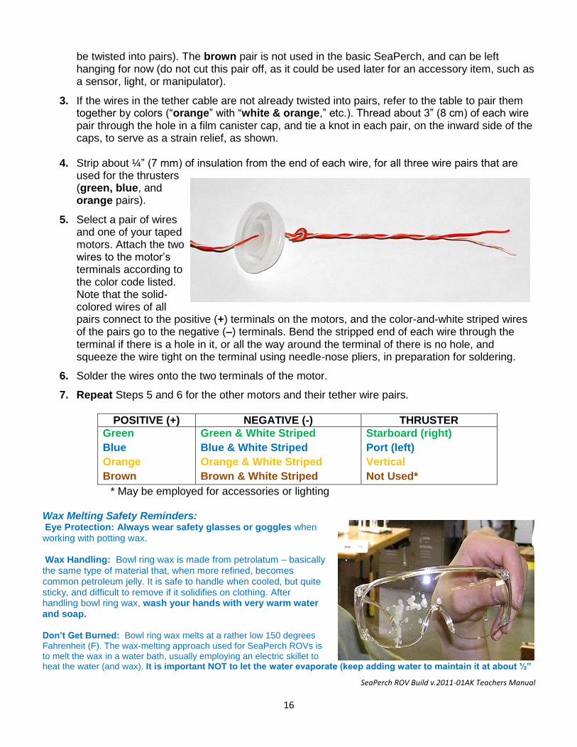
5. Select a pair of wires and one of your taped motors. Attach the two wires to the motor’s terminals according to the color code listed. Note that the solid-colored wires of all pairs connect to the positive (+) terminals on the motors, and the color-and-white striped wires of the pairs go to the negative (–) terminals. Bend the stripped end of each wire through the terminal if there is a hole in it, or all the way around the terminal of there is no hole, and squeeze the wire tight on the terminal using needle-nose pliers, in preparation for soldering.
6. Solder the wires onto the two terminals of the motor.
7. Repeat Steps 5 and 6 for the other motors and their tether wire pairs.
POSITIVE (+) NEGATIVE (-) THRUSTER
Green
Blue
Orange
Brown
Green & White Striped
Blue & White Striped
Orange & White Striped
Brown & White Striped
Starboard (right)
Port (left)
Vertical
Not Used*
* May be employed for accessories or lighting Wax Melting Safety Reminders: Eye Protection: Always wear safety glasses or goggles when working with potting wax. Wax Handling: Bowl ring wax is made from petrolatum – basically the same type of material that, when more refined, becomes common petroleum jelly. It is safe to handle when cooled, but quite sticky, and difficult to remove if it solidifies on clothing. After handling bowl ring wax, wash your hands with very warm water and soap. Don’t Get Burned: Bowl ring wax melts at a rather low 150 degrees Fahrenheit (F). The wax-melting approach used for SeaPerch ROVs is to melt the wax in a water bath, usually employing an electric skillet to heat the water (and wax). It is important NOT to let the water evaporate (keep adding water to maintain it at about ½”
SeaPerch ROV Build v.2011-01AK Teachers Manual
17
to 1” deep); otherwise, the wax can get VERY hot. Although its flash point is over 500 degrees F, the manufacturers usually recommend not exceeding 200 degrees F. If the wax is allowed to get too hot, serious skin burns are possible. In case of a burn, quickly rinse the area with LOTS of cold water and seek medical attention. Don’t Have a Melt-Down: Too-hot wax, such as from using a hot plate without a water bath, has been shown to actually melt the thruster housings! For this reason, and the safety reasons noted above, use of a thermometer for the wax cup(s) is recommended. If a thermometer is not available, the best advice is to keep the water bath below the boiling point, and adjust the skillet temperature to low or medium, so that the wax just reaches its melting point, or a little higher, about 160 degrees F. The goal is for the wax to be hot enough that it will not harden immediately when poured into the thruster housings, but cool enough to avoid burn hazards.
Watch Out for Squirting Wax: Wax can squirt quite a distance when the caps are pressed onto the thruster housings if the task is done very quickly (wax can jet out of the hole in the cap). Wearing an apron and gloves (latex, nitrile, etc.) during the motor potting process is recommended. Holding a paper towel over the cap as it is pressed on will help to prevent wax from squirting beyond the area of the housing. The inside-seal type housings (some film canisters) tend to squirt wax farther than the outside seal types, but either can be a squirting hazard. The picture to the right says it all; wear that eye protection! Wax Melting Technique Tips: 1. To facilitate cleanup, put a drop cloth on the work bench, on the floor below it, and on the wall behind it. When installing caps, stand back to avoid getting wax on you or your (or others’) clothes. 2. Start the wax melting early, at least an hour before class time on motor-potting days. 3. Put small weights (such as lead sinkers) in your wax-melting cup(s), to prevent floating in the water. 4. Try to find metal cups with insulated handles that can hang over the side of the electric skillet or other water-bath heating device. This makes handling and pouring much easier than using tongs or gloves on a hot cup. 5. One wax ring will pot about six thrusters, but plan on some spillage; have extra wax on hand! 6. Should wax run short, spilled wax can be scraped up from the potting holder, table top, or even the outside of the cooling thruster housings and returned to the cup(s) to be re-melted.
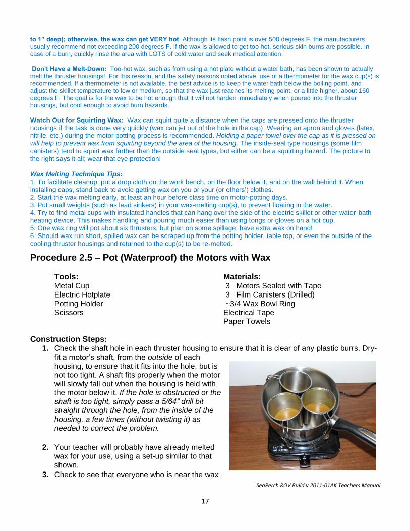
Procedure 2.5 – Pot (Waterproof) the Motors with Wax Tools: Materials: Metal Cup 3 Motors Sealed with Tape Electric Hotplate 3 Film Canisters (Drilled) Potting Holder ~3/4 Wax Bowl Ring Scissors Electrical Tape Paper Towels
Construction Steps: 1. Check the shaft hole in each thruster housing to ensure that it is clear of any plastic burrs. Dry-
fit a motor’s shaft, from the outside of each housing, to ensure that it fits into the hole, but is not too tight. A shaft fits properly when the motor will slowly fall out when the housing is held with the motor below it. If the hole is obstructed or the shaft is too tight, simply pass a 5/64” drill bit straight through the hole, from the inside of the housing, a few times (without twisting it) as needed to correct the problem.
2. Your teacher will probably have already melted wax for your use, using a set-up similar to that shown.
3. Check to see that everyone who is near the wax
SeaPerch ROV Build v.2011-01AK Teachers Manual
18
potting area has put on EYE PROTECTION before anyone begins to work with the hot wax.
4. Dip the ends (1/2 inch) of the brown wire pair (if not being used) in the melted wax to waterproof them.
5. Just before starting the motor-potting process, hold the motors tightly in your closed hand for a minute or so, to warm them up a bit. This will help to prevent rapid cooling of the wax and give you a little more time to settle each motor into position at the bottom of its thruster housing.
6. Pick up one of the thruster housings and carefully insert a motor so that just the tip of the motor’s shaft protrudes from the hole in the bottom. Support the shaft’s tip with a finger to keep the motor from settling all the way into the bottom of the housing.
7. Carefully lift the cup of molten wax from the heated water (if it has no handle, use pliers), and, while continuing to support the shaft tip, pour about ½” (7 mm) of wax (not more!) into the thruster housing along the side of the motor. Then remove your finger from the tip of the shaft and gently settle the motor down into the bottom of the thruster housing. The wax will push part of the way up around the sides of the motor, but it should not move all of the way to the top of the motor, or above it. Carefully place the thruster housing into the potting holder to allow the wax to solidify before performing the additional wax pours.
8. Repeat Steps 5 through 7 for the other two motors.
9. Let the wax cool and harden for several minutes. One end of each motor is now sealed in the wax, so be careful not to push on the motor shafts and break the seals. Once all three of your housings have a motor in them, and have cooled, you will fill them the rest of the way with wax, in two steps.
10. Again carefully lifting the hot container of wax, fill one thruster housing with wax up to about ½” (13 mm) below the top. Pour the wax so that it fills in all the air spaces around the motor. Lift your container and look at it from the side to see if you have any air bubbles. Quickly try to get any bubbles out while the wax is still liquid by gently tilting and squeezing the housing if needed.
11. Return the housing to the potting holder to allow the wax to solidify, and repeat Step 11 for the other two motors.
13. Once the wax has solidified, push the caps up to the knots in the wires and coil the wires into the housings. Make sure that the caps will fit on with the coiled wire in place, and then remove them again in preparation for the final wax pour. Keep the coiled wires away from the top edge of the housing, where they could be pinched.
14. Carefully fill one thruster housing to the very top with wax, creating a positive meniscus as shown.
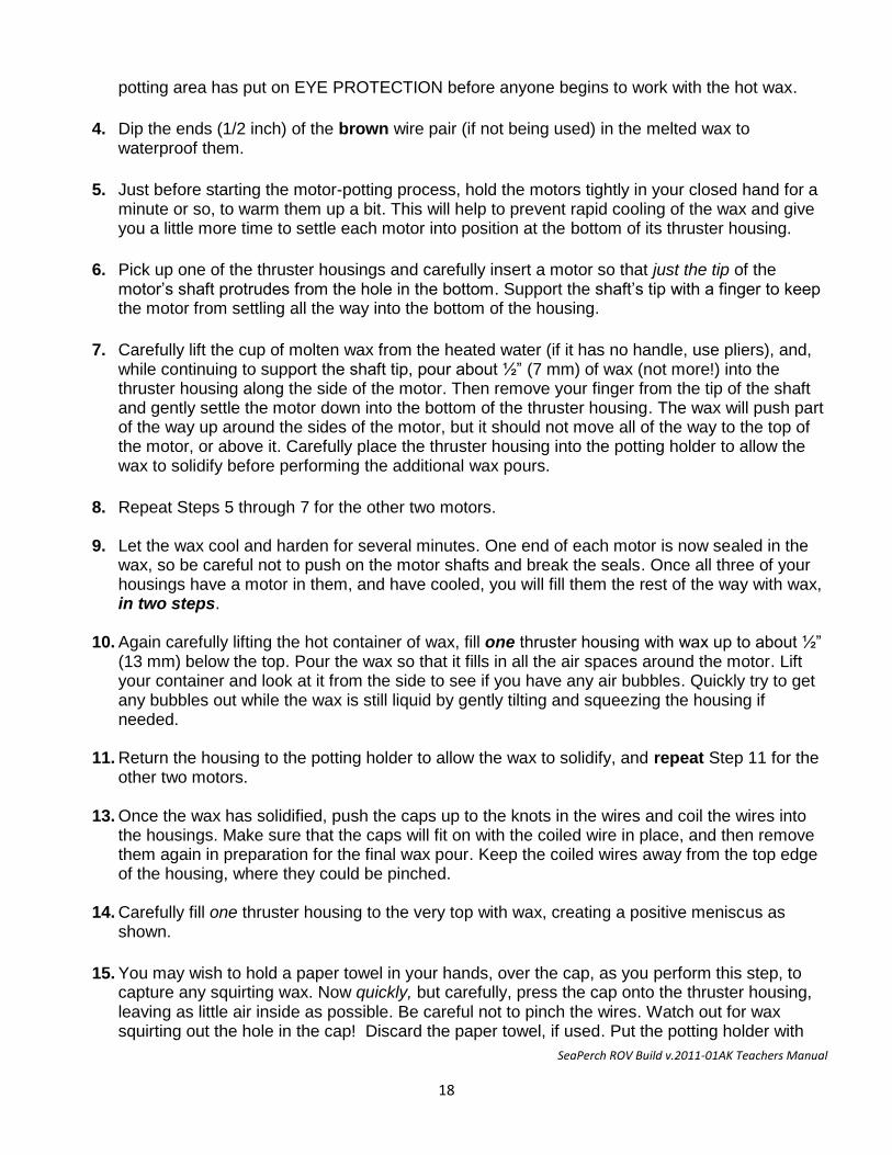
15. You may wish to hold a paper towel in your hands, over the cap, as you perform this step, to capture any squirting wax. Now quickly, but carefully, press the cap onto the thruster housing, leaving as little air inside as possible. Be careful not to pinch the wires. Watch out for wax squirting out the hole in the cap! Discard the paper towel, if used. Put the potting holder with
SeaPerch ROV Build v.2011-01AK Teachers Manual
19
this filled housing in a safe place to cool for about 10 minutes, with the wires extending straight out of the lid (not down to the side). Try not to move the wires again until the wax has cooled and solidified. Also wait until then to wipe off any excess wax that may remain on the sides of the housing.
16. Repeat Steps 14 and 15 for the other two motors. Handle the wires and potted motors very
carefully throughout the remaining construction steps in order to minimize the chance of damage to the shaft or tether wire sealing areas.
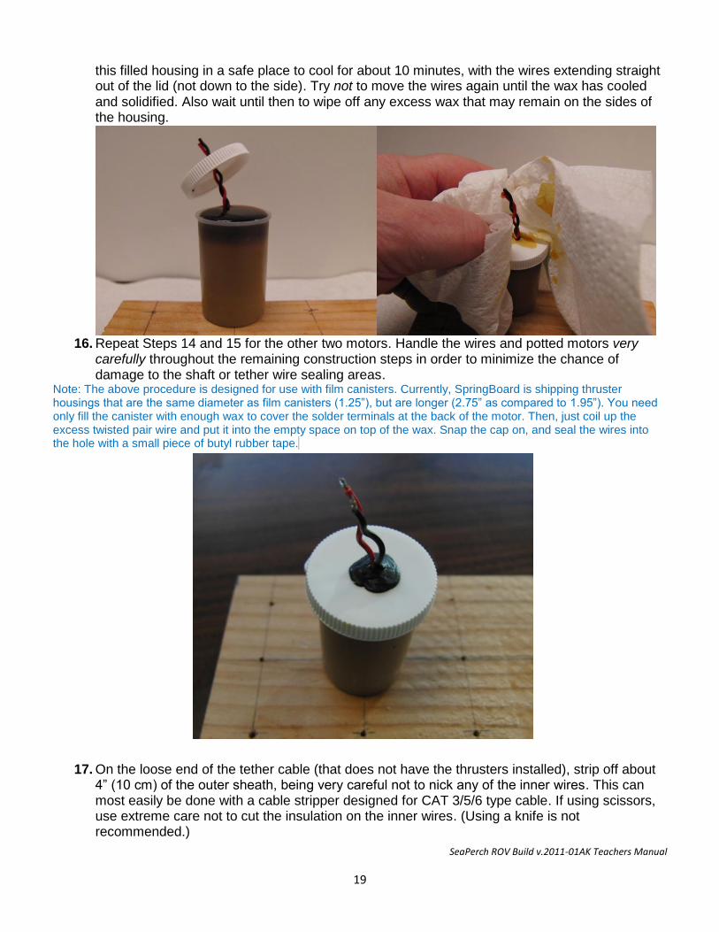
Note: The above procedure is designed for use with film canisters. Currently, SpringBoard is shipping thruster housings that are the same diameter as film canisters (1.25”), but are longer (2.75” as compared to 1.95”). You need only fill the canister with enough wax to cover the solder terminals at the back of the motor. Then, just coil up the excess twisted pair wire and put it into the empty space on top of the wax. Snap the cap on, and seal the wires into the hole with a small piece of butyl rubber tape.
17. On the loose end of the tether cable (that does not have the thrusters installed), strip off about 4” (10 cm) of the outer sheath, being very careful not to nick any of the inner wires. This can most easily be done with a cable stripper designed for CAT 3/5/6 type cable. If using scissors, use extreme care not to cut the insulation on the inner wires. (Using a knife is not recommended.)
SeaPerch ROV Build v.2011-01AK Teachers Manual
20
18. Separate the wires pairs, untwist them for about 1 inch, and strip ¼” of insulation off all wires
except for the brown/brown-white striped pair.
19. One at a time, test each thruster by momentarily touching the two wires from its color-coded wire pair to the two terminals of a 12 volt battery (the polarity does not matter). The motor shaft should spin rapidly, indicating that the thruster is good. If it does not spin, or spins slowly, gently twist it in both directions by hand or, if it seems stuck, use pliers to turn the shaft, and repeat the above test with the battery.
20. If it still does not work, inspect the wires for nicks that may have broken a wire. If a wire has been broken, it can be repaired by stripping about ¼” of insulation from the broken ends and splicing them back together (twist and solder them, and cover the connection with electrical tape).
21. If the thruster still does not work, it will need to be replaced by obtaining another thruster housing and motor, cutting the thruster wire as close as possible to the non-working thruster housing, and repeating procedures 2-1 through 2-5 for the new thruster. Alternately, the non-working thruster can be disassembled to see if a wire may have broken away from one of the electrical terminals on the motor. If that is the reason for the failure (rather than wax having somehow entered the motor shell), the wax can be removed from the back area of the housing to allow the connection to be repaired, and then the wax can be replaced. However, starting with a new thruster may be easier.
22. Test any new or repaired thrusters as above to make sure that they spin properly.
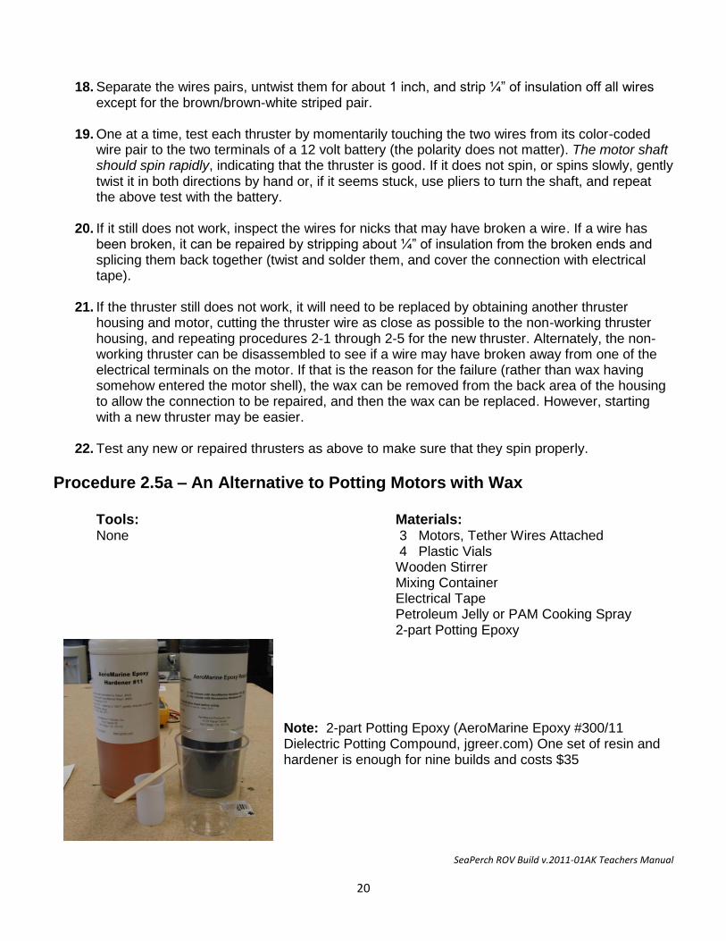
Procedure 2.5a – An Alternative to Potting Motors with Wax Tools: Materials: None 3 Motors, Tether Wires Attached 4 Plastic Vials Wooden Stirrer Mixing Container Electrical Tape Petroleum Jelly or PAM Cooking Spray 2-part Potting Epoxy
Note: 2-part Potting Epoxy (AeroMarine Epoxy #300/11 Dielectric Potting Compound, jgreer.com) One set of resin and hardener is enough for nine builds and costs $35
SeaPerch ROV Build v.2011-01AK Teachers Manual
21
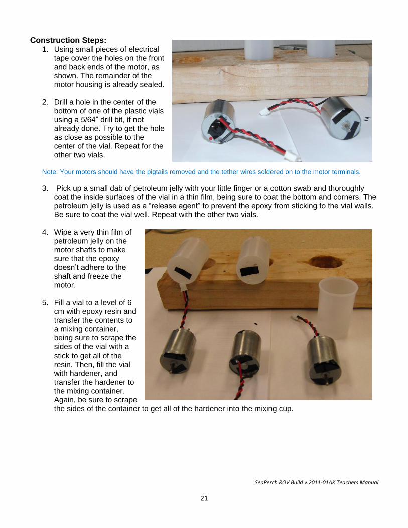
Construction Steps: 1. Using small pieces of electrical
tape cover the holes on the front and back ends of the motor, as shown. The remainder of the motor housing is already sealed.
2. Drill a hole in the center of the bottom of one of the plastic vials using a 5/64” drill bit, if not already done. Try to get the hole as close as possible to the center of the vial. Repeat for the other two vials.
Note: Your motors should have the pigtails removed and the tether wires soldered on to the motor terminals.
3. Pick up a small dab of petroleum jelly with your little finger or a cotton swab and thoroughly coat the inside surfaces of the vial in a thin film, being sure to coat the bottom and corners. The petroleum jelly is used as a “release agent” to prevent the epoxy from sticking to the vial walls. Be sure to coat the vial well. Repeat with the other two vials.
4. Wipe a very thin film of petroleum jelly on the motor shafts to make sure that the epoxy doesn’t adhere to the shaft and freeze the motor.
5. Fill a vial to a level of 6 cm with epoxy resin and transfer the contents to a mixing container, being sure to scrape the sides of the vial with a stick to get all of the resin. Then, fill the vial with hardener, and transfer the hardener to the mixing container. Again, be sure to scrape the sides of the container to get all of the hardener into the mixing cup.
SeaPerch ROV Build v.2011-01AK Teachers Manual
22
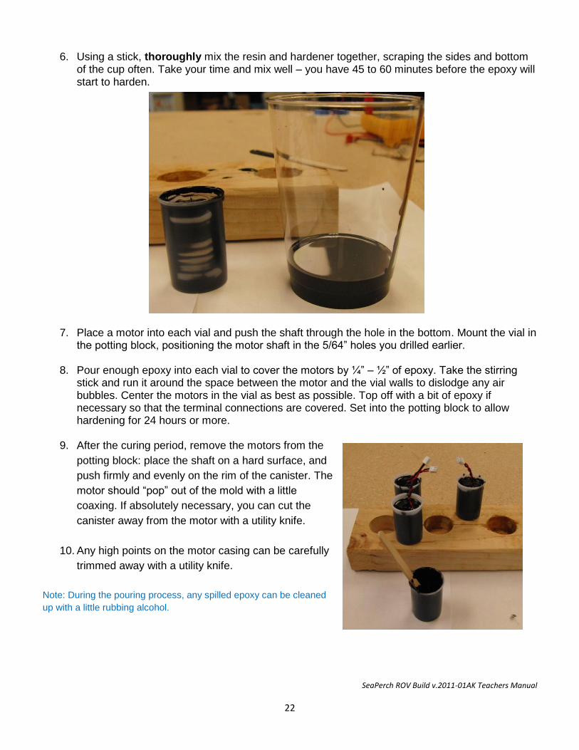
6. Using a stick, thoroughly mix the resin and hardener together, scraping the sides and bottom of the cup often. Take your time and mix well – you have 45 to 60 minutes before the epoxy will start to harden.
7. Place a motor into each vial and push the shaft through the hole in the bottom. Mount the vial in
the potting block, positioning the motor shaft in the 5/64” holes you drilled earlier.
8. Pour enough epoxy into each vial to cover the motors by ¼” – ½” of epoxy. Take the stirring stick and run it around the space between the motor and the vial walls to dislodge any air bubbles. Center the motors in the vial as best as possible. Top off with a bit of epoxy if necessary so that the terminal connections are covered. Set into the potting block to allow hardening for 24 hours or more.
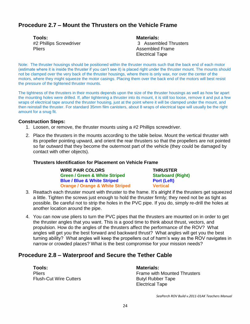
9. After the curing period, remove the motors from the
potting block: place the shaft on a hard surface, and
push firmly and evenly on the rim of the canister. The
motor should “pop” out of the mold with a little
coaxing. If absolutely necessary, you can cut the
canister away from the motor with a utility knife.
10. Any high points on the motor casing can be carefully
trimmed away with a utility knife.
Note: During the pouring process, any spilled epoxy can be cleaned
up with a little rubbing alcohol.

SeaPerch ROV Build v.2011-01AK Teachers Manual
23
Procedure 2.6 – Mounting the Propellers on the Thruster Motors Tools: Materials: Drill 3 Potted Motors 5/64” Drill Bit 3 Propellers Locking Thin-Nose Pliers 3 1/8” x 3/4” Styrene bushings 1/8” Drill Bit Alcohol Paper Towel Sandpaper
Construction Steps: 1. Wipe the shaft of each motor with a piece of paper towel wetted with some rubbing alcohol to
remove any dirt, wax, or petroleum jelly left from the potting process.
2. Use a small piece of sandpaper to roughen the surface of the motor shaft. Wipe one more time with the paper towel.
3. Examine a propeller and note that one side has a slot (groove) cut into it. This is the side of the propeller that must face toward the thruster when the propeller is installed. Take a bushing and try to insert it into the mounting hole in the propeller. If the bushing doesn’t fit, take a 1/8” drill bit and, holding it in the teeth of a pair of pliers, use it to enlarge the hole by spinning the propeller onto the drill bit. Do Not use a drill to power the bit for this procedure.
4. Press the propeller onto the bushing to its full depth.
5. Using a 5/64” drill bit mounted in a drill, enlarge the hole in the styrene bushing by carefully drilling out the interior of the bushing. Be careful to not make the hole too large or the bushing will slip off the shaft easily.
6. Press the propeller/bushing assembly onto the shaft of the motor. You will need to lightly tap the assembly with a pair of pliers to set the bushing on the shaft. Be sure that the fit is firm and that the propeller will not slip off when lightly pulled.
SeaPerch ROV Build v.2011-01AK Teachers Manual
24
Procedure 2.7 – Mount the Thrusters on the Vehicle Frame Tools: Materials: #2 Phillips Screwdriver 3 Assembled Thrusters Pliers Assembled Frame Electrical Tape Note: The thruster housings should be positioned within the thruster mounts such that the back end of each motor (estimate where it is inside the thruster if you can’t see it) is placed right under the thruster mount. The mounts should not be clamped over the very back of the thruster housings, where there is only wax, nor over the center of the motors, where they might squeeze the motor casings. Placing them over the back end of the motors will best resist the pressure of the tightened thruster mounts. The tightness of the thrusters in their mounts depends upon the size of the thruster housings as well as how far apart the mounting holes were drilled. If, after tightening a thruster into its mount, it is still too loose, remove it and put a few wraps of electrical tape around the thruster housing, just at the point where it will be clamped under the mount, and then reinstall the thruster. For standard 35mm film canisters, about 8 wraps of electrical tape will usually be the right amount for a snug fit.
Construction Steps: 1. Loosen, or remove, the thruster mounts using a #2 Phillips screwdriver.
2. Place the thrusters in the mounts according to the table below. Mount the vertical thruster with its propeller pointing upward, and orient the rear thrusters so that the propellers are not pointed so far outward that they become the outermost part of the vehicle (they could be damaged by contact with other objects). Thrusters Identification for Placement on Vehicle Frame
3. Reattach each thruster mount with thruster to the frame. It’s alright if the thrusters get squeezed a little. Tighten the screws just enough to hold the thruster firmly; they need not be as tight as possible. Be careful not to strip the holes in the PVC pipe. If you do, simply re-drill the holes at another location around the pipe.
4. You can now use pliers to turn the PVC pipes that the thrusters are mounted on in order to get the thruster angles that you want. This is a good time to think about thrust, vectors, and propulsion. How do the angles of the thrusters affect the performance of the ROV? What angles will get you the best forward and backward thrust? What angles will get you the best turning ability? What angles will keep the propellers out of harm’s way as the ROV navigates in narrow or crowded places? What is the best compromise for your mission needs?
Procedure 2.8 – Waterproof and Secure the Tether Cable Tools: Materials: Pliers Frame with Mounted Thrusters Flush-Cut Wire Cutters Butyl Rubber Tape Electrical Tape
WIRE PAIR COLORS THRUSTER Green / Green & White Striped Blue / Blue & White Striped Orange / Orange & White Striped
Starboard (Right) Port (Left) Vertical
SeaPerch ROV Build v.2011-01AK Teachers Manual
25
Construction Steps: 1. Locate the point near the thruster end of the tether cable where the four thruster wire pairs
emerge from the cable sheath, and bring it out a bit away from the vehicle frame so you can waterproof that opening using butyl rubber tape.
2. Locate in your kit (or cut from a roll) a 1” (2.5 cm) piece of butyl rubber tape.
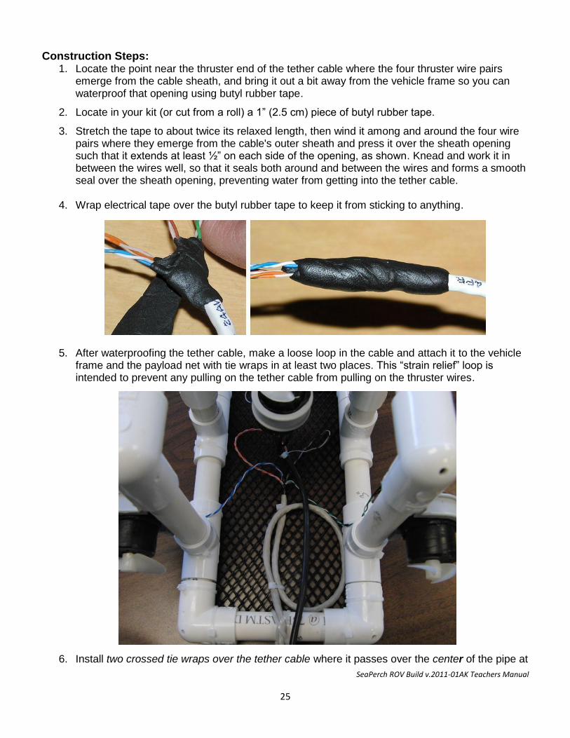
3. Stretch the tape to about twice its relaxed length, then wind it among and around the four wire pairs where they emerge from the cable's outer sheath and press it over the sheath opening such that it extends at least ½” on each side of the opening, as shown. Knead and work it in between the wires well, so that it seals both around and between the wires and forms a smooth seal over the sheath opening, preventing water from getting into the tether cable.
4. Wrap electrical tape over the butyl rubber tape to keep it from sticking to anything.
5. After waterproofing the tether cable, make a loose loop in the cable and attach it to the vehicle frame and the payload net with tie wraps in at least two places. This “strain relief” loop is intended to prevent any pulling on the tether cable from pulling on the thruster wires.
6. Install two crossed tie wraps over the tether cable where it passes over the center of the pipe at
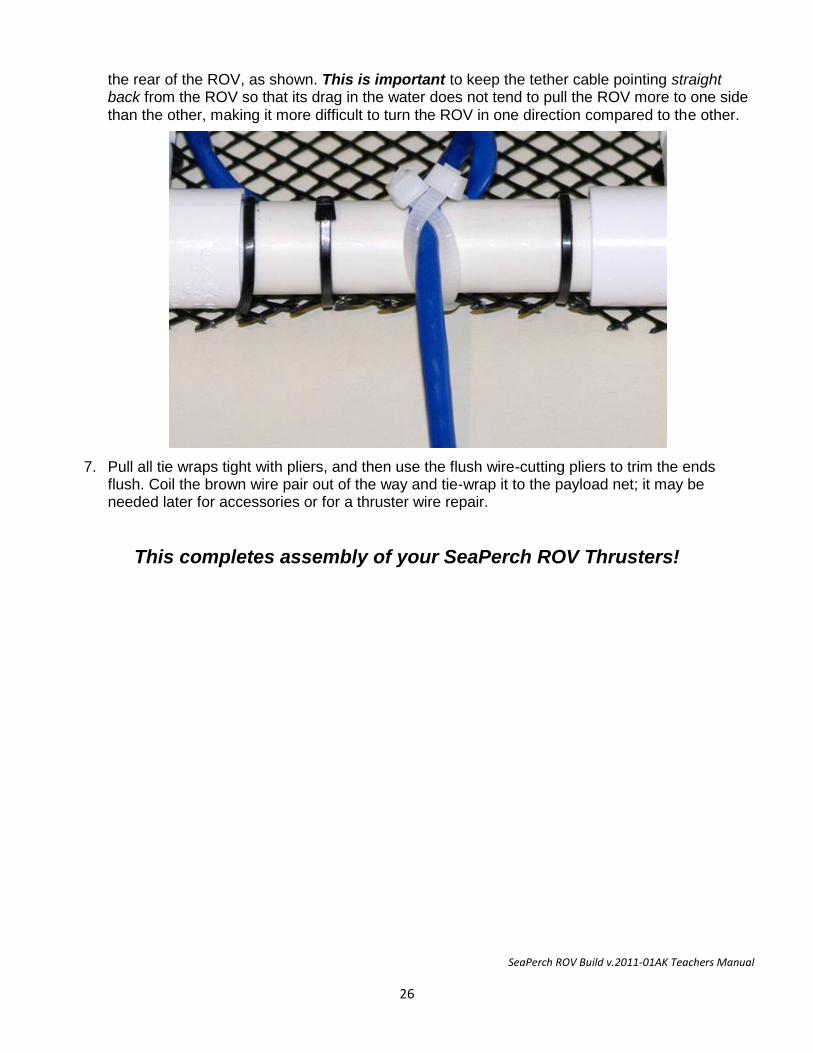
SeaPerch ROV Build v.2011-01AK Teachers Manual
26
the rear of the ROV, as shown. This is important to keep the tether cable pointing straight back from the ROV so that its drag in the water does not tend to pull the ROV more to one side than the other, making it more difficult to turn the ROV in one direction compared to the other.
7. Pull all tie wraps tight with pliers, and then use the flush wire-cutting pliers to trim the ends flush. Coil the brown wire pair out of the way and tie-wrap it to the payload net; it may be needed later for accessories or for a thruster wire repair.
This completes assembly of your SeaPerch ROV Thrusters!

SeaPerch ROV Build v.2011-01AK Teachers Manual
27
SeaPerch Remotely Operated Vehicle
Assembly of Subsystem Three The Control Box
January 2011
Version 2011-01AK
SeaPerch ROV Build v.2011-01AK Teachers Manual
28
Time Needed to
Tools and Materials Needed Tools: Materials: Eye Protection Completed Vehicle Frame/Thrusters Drill Project Box ¼” Drill Bit 10’ #18 Lamp Cord or Speaker Wire (paired) Pliers 24” #22 Stranded Hook-up Wire, Red Wire Stripper 24” #22 Stranded Hook-up Wire, Black Flush-cut Wire Cutters 2 Slide Terminals Soldering Iron and Solder (Rosin Core) 1 Fuse Holder and 7A Slo-Blow Fuse #2 Phillips Screwdriver 3 DPDT Momentary Toggle Switches Vise or Clamp Electrical Tape 12 VDC Battery
Total Construction Time: Unit 3 usually requires about 7 hours to complete. More time should be allowed if the class is building a large number of ROVs.
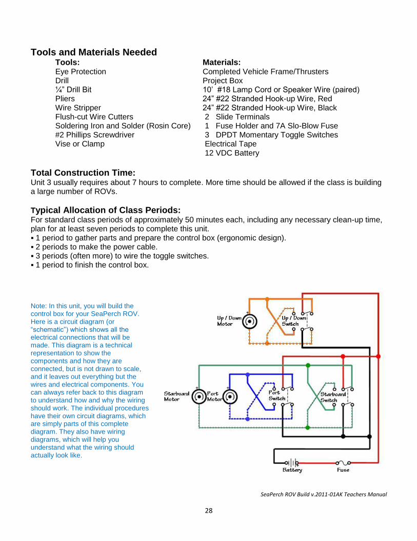
Typical Allocation of Class Periods: For standard class periods of approximately 50 minutes each, including any necessary clean-up time, plan for at least seven periods to complete this unit. 1 period to gather parts and prepare the control box (ergonomic design). 2 periods to make the power cable. 3 periods (often more) to wire the toggle switches. 1 period to finish the control box. Note: In this unit, you will build the control box for your SeaPerch ROV. Here is a circuit diagram (or “schematic”) which shows all the electrical connections that will be made. This diagram is a technical representation to show the components and how they are connected, but is not drawn to scale, and it leaves out everything but the wires and electrical components. You can always refer back to this diagram to understand how and why the wiring should work. The individual procedures have their own circuit diagrams, which are simply parts of this complete diagram. They also have wiring diagrams, which will help you understand what the wiring should actually look like.
SeaPerch ROV Build v.2011-01AK Teachers Manual
29
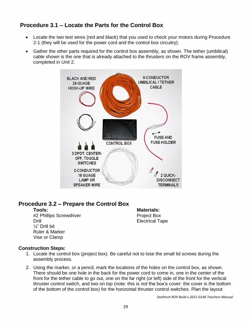
Procedure 3.1 – Locate the Parts for the Control Box
Locate the two test wires (red and black) that you used to check your motors during Procedure 2-1 (they will be used for the power cord and the control box circuitry).
Gather the other parts required for the control box assembly, as shown. The tether (umbilical) cable shown is the one that is already attached to the thrusters on the ROV frame assembly, completed in Unit 2.
Procedure 3.2 – Prepare the Control Box Tools: Materials: #2 Phillips Screwdriver Project Box Drill Electrical Tape ¼” Drill bit Ruler & Marker Vise or Clamp
Construction Steps: 1. Locate the control box (project box). Be careful not to lose the small lid screws during the
assembly process.
2. Using the marker, or a pencil, mark the locations of the holes on the control box, as shown. There should be one hole in the back for the power cord to come in, one in the center of the front for the tether cable to go out, one on the far right (or left) side of the front for the vertical thruster control switch, and two on top (note: this is not the box’s cover: the cover is the bottom of the bottom of the control box) for the horizontal thruster control switches. Plan the layout
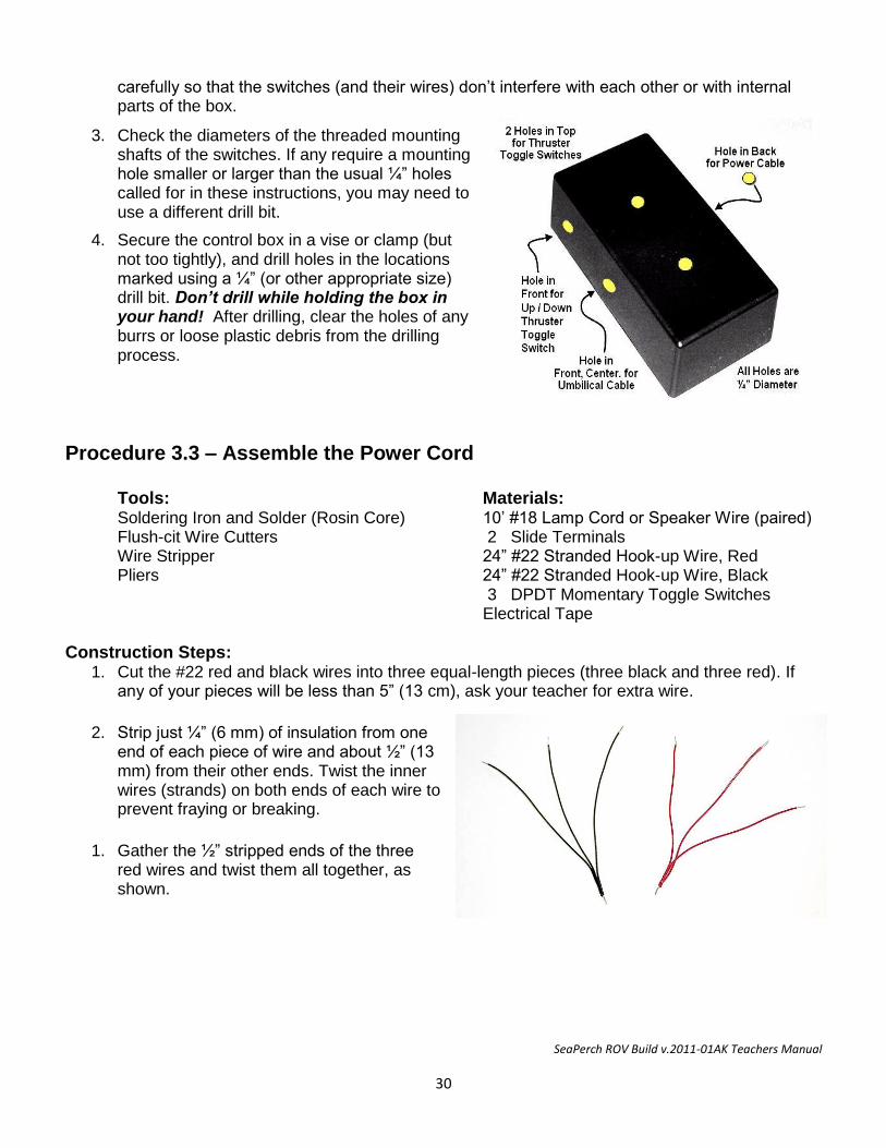
SeaPerch ROV Build v.2011-01AK Teachers Manual
30
carefully so that the switches (and their wires) don’t interfere with each other or with internal parts of the box.
3. Check the diameters of the threaded mounting shafts of the switches. If any require a mounting hole smaller or larger than the usual ¼” holes called for in these instructions, you may need to use a different drill bit.
4. Secure the control box in a vise or clamp (but not too tightly), and drill holes in the locations marked using a ¼” (or other appropriate size) drill bit. Don’t drill while holding the box in your hand! After drilling, clear the holes of any burrs or loose plastic debris from the drilling process.
Procedure 3.3 – Assemble the Power Cord Tools: Materials: Soldering Iron and Solder (Rosin Core) 10’ #18 Lamp Cord or Speaker Wire (paired) Flush-cit Wire Cutters 2 Slide Terminals Wire Stripper 24” #22 Stranded Hook-up Wire, Red Pliers 24” #22 Stranded Hook-up Wire, Black 3 DPDT Momentary Toggle Switches Electrical Tape
Construction Steps: 1. Cut the #22 red and black wires into three equal-length pieces (three black and three red). If
any of your pieces will be less than 5” (13 cm), ask your teacher for extra wire.
2. Strip just ¼” (6 mm) of insulation from one end of each piece of wire and about ½” (13 mm) from their other ends. Twist the inner wires (strands) on both ends of each wire to prevent fraying or breaking.
1. Gather the ½” stripped ends of the three red wires and twist them all together, as shown.
SeaPerch ROV Build v.2011-01AK Teachers Manual
31
2. Do the same with the three black wires. These spliced wire bundles will distribute power in your control box.
3. Find the power cord wire (#18 speaker wire or lamp cord), and determine which of its two
conductors will be positive and which will be negative. To do this, note that each conductor has its own insulation, and that the two are attached to each other with a thin web of insulation material. Usually the insulation on one conductor is ribbed (like corduroy), and the other is smooth. Sometimes, one conductor's insulation is instead marked with white or black stripes, printed information, or other polarity indicators. For some power cords, the insulation is clear but one conductor is silver and the other is copper. For this project, we will call the ribbed, marked, or copper side the positive (+) side, and the smooth, unmarked, or silver side the negative (–) side.
4. On each end of the power cord wire, carefully separate the two conductors for about 1” (2.5 cm). This is best done by snipping the thin web of plastic between the wires with a small pair of scissors or a small pair of wire cutters. Be careful not to nick the insulation on either of the individual conductors.
5. On one end of the power cord wire leave the separated section only 1” (2.5 cm) long. On the other end, pull or cut the two conductors apart for about 8” (20 cm). On the end of the wire that you just separated, find the positive (ribbed or marked) side, and cut off 7” (18 cm) of that conductor. This section will be replaced with the fuse holder.
6. Strip 1/2” (13 mm) of insulation off both of the fuse holder wires. The fuse holder does not have a positive and negative side; it will work either way.
7. Strip 1/2” (13 mm) of insulation off of all four ends of the power cord wire. Twist the strands together on the ends of each conductor to prevent fraying and breaking.
8. Attach the fuse holder wire to the positive (ribbed / marked / copper) side of the power cord
wire, where you previously cut off the 7” (18 cm) piece. Twist the wires tightly together (in-line, as shown in Figure 3.3-4), solder the connection, and cover it with electrical tape.
11. Slide the “+” quick-disconnect terminal onto the loose end of the fuse holder wire, and crimp it firmly using a crimping tool or pliers. You may solder this connection if it appears to be loose after crimping; however, try not to overheat the terminal’s colored, identifying insulation.
12. Slide the “–” quick-disconnect terminal onto the negative side of the power cord, and crimp it (and optionally solder it) as above. Use a black permanent marking pen to color the insulator (usually pink) of this terminal black, indicating negative polarity. At this point, the end of your power cable should look like the picture above.
13. Pass the loose end of the power cable (no fuse holder) through the hole in the back of your
control box, from the outside. Tie a strain-relief knot about 6” (15 cm) up the cord on the inside of the control box.
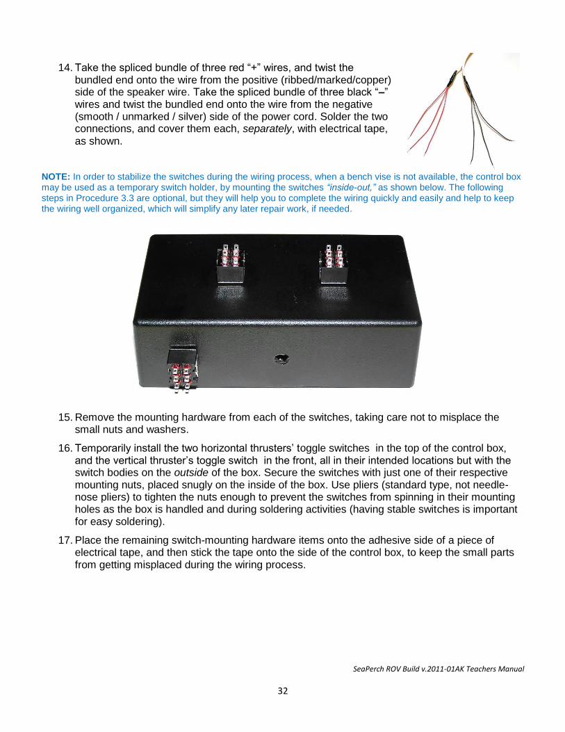
SeaPerch ROV Build v.2011-01AK Teachers Manual
32
14. Take the spliced bundle of three red “+” wires, and twist the
bundled end onto the wire from the positive (ribbed/marked/copper) side of the speaker wire. Take the spliced bundle of three black “–” wires and twist the bundled end onto the wire from the negative (smooth / unmarked / silver) side of the power cord. Solder the two connections, and cover them each, separately, with electrical tape, as shown.
NOTE: In order to stabilize the switches during the wiring process, when a bench vise is not available, the control box may be used as a temporary switch holder, by mounting the switches “inside-out,” as shown below. The following steps in Procedure 3.3 are optional, but they will help you to complete the wiring quickly and easily and help to keep the wiring well organized, which will simplify any later repair work, if needed.
15. Remove the mounting hardware from each of the switches, taking care not to misplace the small nuts and washers.
16. Temporarily install the two horizontal thrusters’ toggle switches in the top of the control box, and the vertical thruster’s toggle switch in the front, all in their intended locations but with the switch bodies on the outside of the box. Secure the switches with just one of their respective mounting nuts, placed snugly on the inside of the box. Use pliers (standard type, not needle-nose pliers) to tighten the nuts enough to prevent the switches from spinning in their mounting holes as the box is handled and during soldering activities (having stable switches is important for easy soldering).
17. Place the remaining switch-mounting hardware items onto the adhesive side of a piece of electrical tape, and then stick the tape onto the side of the control box, to keep the small parts from getting misplaced during the wiring process.
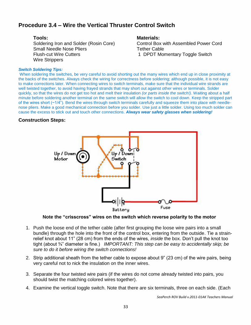
SeaPerch ROV Build v.2011-01AK Teachers Manual
33
Procedure 3.4 – Wire the Vertical Thruster Control Switch Tools: Materials: Soldering Iron and Solder (Rosin Core) Control Box with Assembled Power Cord Small Needle Nose Pliers Tether Cable Flush-cut Wire Cutters 1 DPDT Momentary Toggle Switch Wire Strippers Switch Soldering Tips: When soldering the switches, be very careful to avoid shorting out the many wires which end up in close proximity at the backs of the switches. Always check the wiring for correctness before soldering; although possible, it is not easy to make corrections later. When connecting wires to switch terminals, make sure that the individual wire strands are well twisted together, to avoid having frayed strands that may short out against other wires or terminals. Solder quickly, so that the wires do not get too hot and melt their insulation (or parts inside the switch!). Waiting about a half minute before soldering another terminal on the same switch will allow the switch to cool down. Keep the stripped part of the wires short (~1/4”). Bend the wires through switch terminals carefully and squeeze them into place with needle-nose pliers. Make a good mechanical connection before you solder. Use just a little solder. Using too much solder can cause the excess to stick out and touch other connections. Always wear safety glasses when soldering!
Construction Steps:
Note the “crisscross” wires on the switch which reverse polarity to the motor
1. Push the loose end of the tether cable (after first grouping the loose wire pairs into a small bundle) through the hole into the front of the control box, entering from the outside. Tie a strain-relief knot about 11” (28 cm) from the ends of the wires, inside the box. Don’t pull the knot too tight (about ¾” diameter is fine.) IMPORTANT: This step can be easy to accidentally skip; be sure to do it before wiring the switch connections!
2. Strip additional sheath from the tether cable to expose about 9” (23 cm) of the wire pairs, being very careful not to nick the insulation on the inner wires.
3. Separate the four twisted wire pairs (if the wires do not come already twisted into pairs, you
should twist the matching colored wires together).
4. Examine the vertical toggle switch. Note that there are six terminals, three on each side. (Each
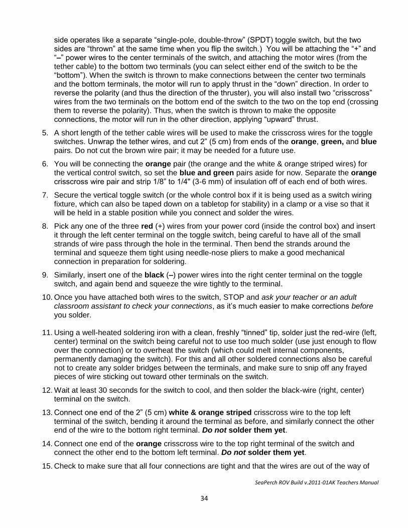
SeaPerch ROV Build v.2011-01AK Teachers Manual
34
side operates like a separate “single-pole, double-throw” (SPDT) toggle switch, but the two sides are “thrown” at the same time when you flip the switch.) You will be attaching the “+” and “–” power wires to the center terminals of the switch, and attaching the motor wires (from the tether cable) to the bottom two terminals (you can select either end of the switch to be the “bottom”). When the switch is thrown to make connections between the center two terminals and the bottom terminals, the motor will run to apply thrust in the “down” direction. In order to reverse the polarity (and thus the direction of the thruster), you will also install two “crisscross” wires from the two terminals on the bottom end of the switch to the two on the top end (crossing them to reverse the polarity). Thus, when the switch is thrown to make the opposite connections, the motor will run in the other direction, applying “upward” thrust.
5. A short length of the tether cable wires will be used to make the crisscross wires for the toggle switches. Unwrap the tether wires, and cut 2” (5 cm) from ends of the orange, green, and blue pairs. Do not cut the brown wire pair; it may be needed for a future use.
6. You will be connecting the orange pair (the orange and the white & orange striped wires) for the vertical control switch, so set the blue and green pairs aside for now. Separate the orange crisscross wire pair and strip 1/8” to 1/4" (3-6 mm) of insulation off of each end of both wires.
7. Secure the vertical toggle switch (or the whole control box if it is being used as a switch wiring fixture, which can also be taped down on a tabletop for stability) in a clamp or a vise so that it will be held in a stable position while you connect and solder the wires.
8. Pick any one of the three red (+) wires from your power cord (inside the control box) and insert it through the left center terminal on the toggle switch, being careful to have all of the small strands of wire pass through the hole in the terminal. Then bend the strands around the terminal and squeeze them tight using needle-nose pliers to make a good mechanical connection in preparation for soldering.
9. Similarly, insert one of the black (–) power wires into the right center terminal on the toggle switch, and again bend and squeeze the wire tightly to the terminal.
10. Once you have attached both wires to the switch, STOP and ask your teacher or an adult classroom assistant to check your connections, as it’s much easier to make corrections before you solder.
11. Using a well-heated soldering iron with a clean, freshly “tinned” tip, solder just the red-wire (left, center) terminal on the switch being careful not to use too much solder (use just enough to flow over the connection) or to overheat the switch (which could melt internal components, permanently damaging the switch). For this and all other soldered connections also be careful not to create any solder bridges between the terminals, and make sure to snip off any frayed pieces of wire sticking out toward other terminals on the switch.
12. Wait at least 30 seconds for the switch to cool, and then solder the black-wire (right, center) terminal on the switch.
13. Connect one end of the 2” (5 cm) white & orange striped crisscross wire to the top left terminal of the switch, bending it around the terminal as before, and similarly connect the other end of the wire to the bottom right terminal. Do not solder them yet.
14. Connect one end of the orange crisscross wire to the top right terminal of the switch and connect the other end to the bottom left terminal. Do not solder them yet.
15. Check to make sure that all four connections are tight and that the wires are out of the way of
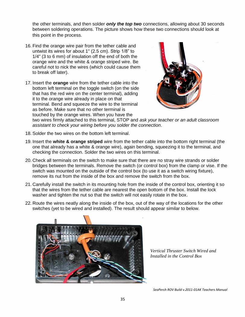
SeaPerch ROV Build v.2011-01AK Teachers Manual
35
the other terminals, and then solder only the top two connections, allowing about 30 seconds between soldering operations. The picture shows how these two connections should look at
this point in the process.ed
16. Find the orange wire pair from the tether cable and
untwist its wires for about 1" (2.5 cm). Strip 1/8” to 1/4" (3 to 6 mm) of insulation off the end of both the orange wire and the white & orange striped wire. Be careful not to nick the wires (which could cause them to break off later).
17. Insert the orange wire from the tether cable into the bottom left terminal on the toggle switch (on the side that has the red wire on the center terminal), adding it to the orange wire already in place on that terminal. Bend and squeeze the wire to the terminal as before. Make sure that no other terminal is touched by the orange wires. When you have the two wires firmly attached to this terminal, STOP and ask your teacher or an adult classroom assistant to check your wiring before you solder the connection.
18. Solder the two wires on the bottom left terminal.
19. Insert the white & orange striped wire from the tether cable into the bottom right terminal (the one that already has a white & orange wire), again bending, squeezing it to the terminal, and checking the connection. Solder the two wires on this terminal.
20. Check all terminals on the switch to make sure that there are no stray wire strands or solder bridges between the terminals. Remove the switch (or control box) from the clamp or vise. If the switch was mounted on the outside of the control box (to use it as a switch wiring fixture), remove its nut from the inside of the box and remove the switch from the box.
21. Carefully install the switch in its mounting hole from the inside of the control box, orienting it so that the wires from the tether cable are nearest the open bottom of the box. Install the lock washer and tighten the nut so that the switch will not easily rotate in the box.
22. Route the wires neatly along the inside of the box, out of the way of the locations for the other switches (yet to be wired and installed). The result should appear similar to below.
Vertical Thruster Switch Wired and
Installed in the Control Box
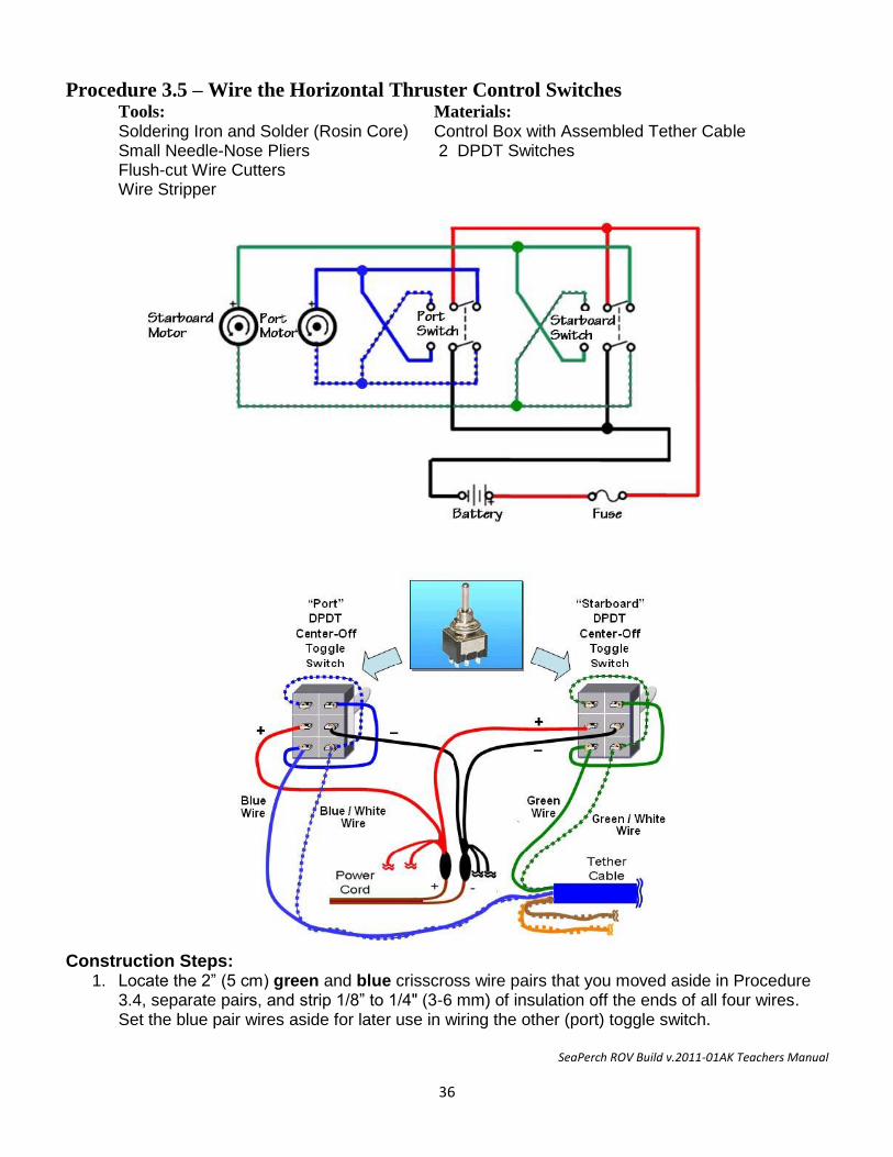
SeaPerch ROV Build v.2011-01AK Teachers Manual
36
Procedure 3.5 – Wire the Horizontal Thruster Control Switches Tools: Materials:
Soldering Iron and Solder (Rosin Core) Control Box with Assembled Tether Cable Small Needle-Nose Pliers 2 DPDT Switches Flush-cut Wire Cutters Wire Stripper
Construction Steps:
1. Locate the 2” (5 cm) green and blue crisscross wire pairs that you moved aside in Procedure 3.4, separate pairs, and strip 1/8” to 1/4" (3-6 mm) of insulation off the ends of all four wires. Set the blue pair wires aside for later use in wiring the other (port) toggle switch.
SeaPerch ROV Build v.2011-01AK Teachers Manual
37
2. Secure the “starboard” (right) control switch (or the whole control box if it is being used as a switch wiring fixture, which can also be taped down on a tabletop for stability) in a clamp or a vise so that it will be held in a stable position while you connect and solder the wires.
3. Pick either of the remaining two red (+) wires from your power cord (from inside the control box), and insert it through the left center terminal on the toggle switch, being careful to have all of the small strands of wire pass through the hole in the terminal. Then bend the strands around the terminal and squeeze them tight using needle-nose pliers to make a good mechanical connection in preparation for soldering. Do not solder the connection yet.
4. Similarly, insert one of the black (–) power wires into the right center terminal on the toggle switch, and again bend and squeeze the wire tightly to the terminal.
5. Using a well-heated soldering iron with a clean, freshly “tinned” tip, solder just the red-wire (left, center) terminal on the switch being careful not to use too much solder (use just enough to flow over the connection) or to overheat the switch (which could melt internal components, permanently damaging the switch). For this and all other soldered connections, be careful not to create any solder bridges between the terminals, and make sure to snip off any frayed pieces of wire sticking out toward other terminals on the switch.
6. Wait at least 30 seconds for the switch to cool, and then solder the black-wire (right, center) terminal on the switch.
7. Connect one end of the 2” (5 cm) green & white striped crisscross wire to the top left terminal of the switch, bending it around the terminal as before, and similarly connect the other end of the wire to the bottom right terminal. Do not solder the connections yet.
8. Connect one end of the green crisscross wire to the top right terminal of the switch, and connect the other end to the bottom left terminal. Do not solder the connections yet.
9. Check to make sure that all four connections are tight and that the wires are out of the way of the other terminals and then solder only the top two connections, allowing about 30 seconds between soldering operations.
10. Take the tether cable’s green wire pair and untwist it for about 1” (2.5 cm). Strip 1/8” to 1/4" (3 to 6 mm) of insulation off the ends of both the green wire and the white & green striped wire. Be careful not to nick the wires (which could cause them to break off later).
11. Insert the green wire into the bottom left terminal on the toggle switch (on the side that has the red wire on the center terminal), adding it to the green wire already in place on that terminal. Bend and squeeze the wire to the terminal as before. Make sure that no other terminal is touched by the green pair wires.
12. Solder the two wires on the bottom left terminal.
13. Insert the white & green striped wire from the tether cable into the bottom right terminal (the one that already has a white & green striped wire connected), again bending, squeezing it to the terminal, and checking the connection. Solder the two wires on this terminal.
14. Check all terminals on the switch to make sure that there are no stray wire strands or solder bridges between the terminals.
15. Insert the remaining red (+) wire from your power cord through the left center terminal on the “port” (left) toggle switch, again being careful to have all of the small strands of wire pass
SeaPerch ROV Build v.2011-01AK Teachers Manual
38
through the hole in the terminal. Bend the strands around the terminal and squeeze them tight using needle-nose pliers as before to make a good mechanical connection in preparation for soldering.
16. Insert the remaining black (–) power wire into the right center terminal on the toggle switch, and again bend and squeeze the wire tightly to the terminal.
17. Using a well-heated soldering iron, with a clean, freshly “tinned” tip, solder just the red-wire (left, center) terminal on the switch.
18. Wait at least 30 seconds for the switch to cool, and then solder the black-wire (right, center) terminal on the switch.
19. Locate the 2” (~5 cm) pieces of wire from the blue wire pair that you cut and set aside earlier, for the crisscross wires for this toggle switch.
20. Connect one end of the white & blue striped crisscross wire to the top left terminal of the switch, bending it around the terminal as before, and similarly connect the other end of the wire to the bottom right terminal. Do not solder them yet.
21. Connect one end of the blue crisscross wire to the top right terminal of the switch, and connect the other end to the bottom left terminal. Do not solder them yet.
22. Check to make sure that all four connections are tight and that the wires are out of the way of the other terminals, and then solder only the top two connections, allowing about 30 seconds between soldering operations.
23. Now take the blue pair from the umbilical / tether cable and untwist the pair for about 1” (2.5 cm). Strip 1/8” to 1/4" (3 to 6 mm) of insulation off the end of both the blue wire and the white & blue striped wire. Again, be careful not to nick the wires.
24. Insert the blue wire into the bottom left terminal on the toggle switch, adding it to the blue wire already in place on that terminal. Bend and squeeze the wire to the terminal as before.
25. Solder the two wires on the bottom left terminal.
26. Insert the white & blue striped wire into the bottom right terminal (the one that already has a white & blue wire), again bending, squeezing it to the terminal, and checking the connection. Solder the two wires on this terminal.
27. Check all terminals on the switch to make sure that there are no stray wire strands or solder
bridges between the terminals.
Procedure 3.5 – Continued
Procedure 3.6 – Finish the Control Box
Tools: Materials; Pliers Wired Control Box #2 Phillips Screwdriver Control Box Cover 4 Control Box Cover Screws Switch Mounting Hardware
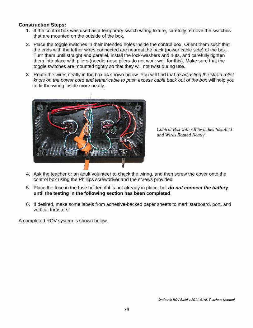
SeaPerch ROV Build v.2011-01AK Teachers Manual
39
Construction Steps: 1. If the control box was used as a temporary switch wiring fixture, carefully remove the switches
that are mounted on the outside of the box.
2. Place the toggle switches in their intended holes inside the control box. Orient them such that the ends with the tether wires connected are nearest the back (power cable side) of the box. Turn them until straight and parallel, install the lock-washers and nuts, and carefully tighten them into place with pliers (needle-nose pliers do not work well for this). Make sure that the toggle switches are mounted tightly so that they will not twist during use.
3. Route the wires neatly in the box as shown below. You will find that re-adjusting the strain relief knots on the power cord and tether cable to push excess cable back out of the box will help you to fit the wiring inside more neatly.
Control Box with All Switches Installed
and Wires Routed Neatly
4. Ask the teacher or an adult volunteer to check the wiring, and then screw the cover onto the control box using the Phillips screwdriver and the screws provided.
5. Place the fuse in the fuse holder, if it is not already in place, but do not connect the battery until the testing in the following section has been completed.
6. If desired, make some labels from adhesive-backed paper sheets to mark starboard, port, and
vertical thrusters. A completed ROV system is shown below.
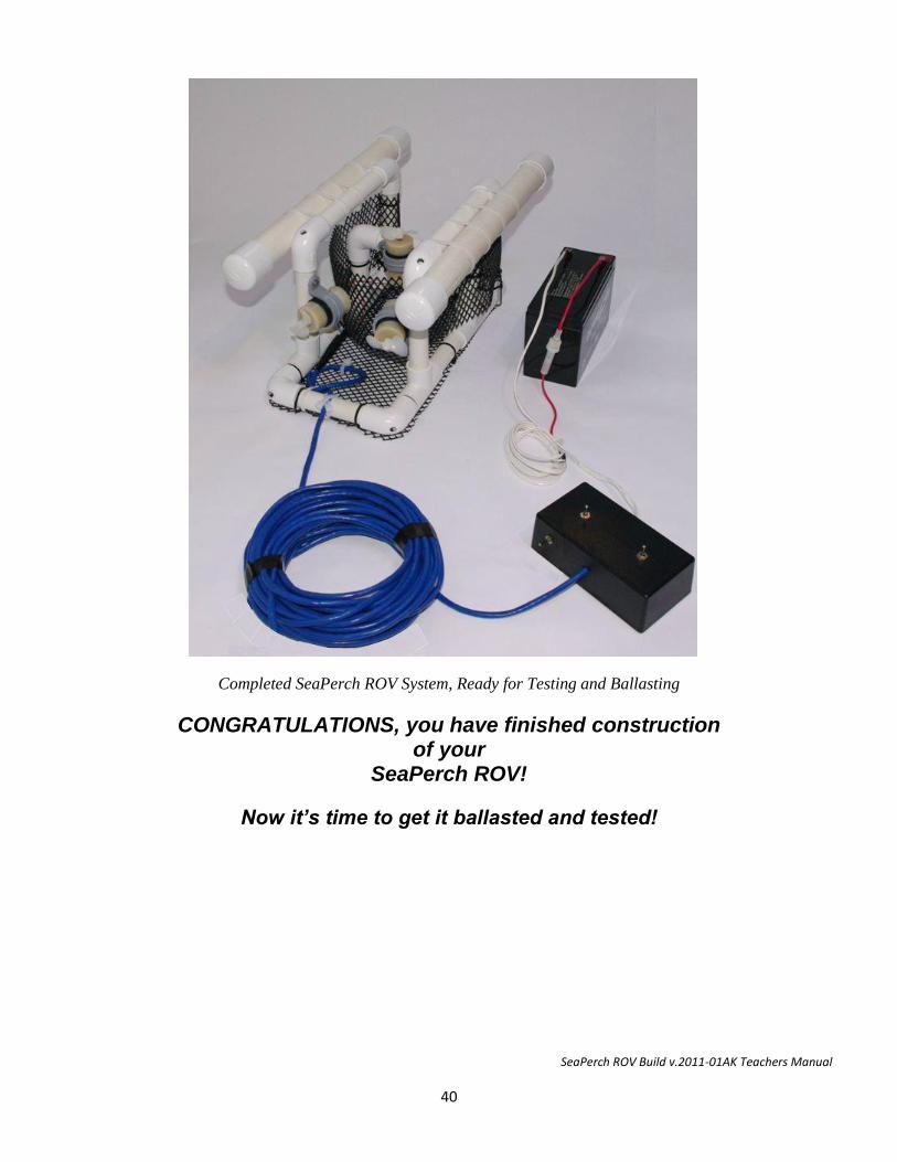
SeaPerch ROV Build v.2011-01AK Teachers Manual
40
Completed SeaPerch ROV System, Ready for Testing and Ballasting
CONGRATULATIONS, you have finished construction of your
SeaPerch ROV!
Now it’s time to get it ballasted and tested!
SeaPerch ROV Build v.2011-01AK Teachers Manual
41
Testing and Ballasting the ROV Time Needed to Complete Testing and Ballasting of the ROV Initial electrical testing usually requires much less than 1 hour, unless the vehicle does not function properly, in which case several hours may be required to resolve the problem(s). Ballasting experimentation and mounting of the final ballast weights usually requires about 1 to 2 hours. With large numbers of ROVs, more time should be allowed if in-water test space and troubleshooting resources are limited.
Typical Allocation of Class Periods: For standard class periods of approximately 50 minutes each, including any necessary clean-up time, plan for at least four periods to test the ROVs and ready them for in-water use. 1 period to perform initial electrical tests, check the operation of the thrusters and control box, and make minor adjustments. 2 periods to review buoyancy concepts (conducting a hands-on “buoyancy lab” session is recommended), determine the amount of ballast needed, and install the weights. 1 class period for troubleshooting and problem solving, which is usually needed for at least a few ROVs per class.
Initial Electrical Testing
Testing Before Connecting the Battery: Conducting a few quick short-circuit tests before connecting the ROV to the battery can prevent a blown fuse, should there be an undetected problem with the ROV’s wiring. The following tests are recommended.
Open-Switch Test: Connect an ohmmeter (multi-meter) or continuity tester across the two power cord wires, where the battery would normally be connected. With all switches in the “off” position, there should be no continuity indicated, and an ohmmeter should read infinite resistance. If there is a continuity indication or if any less than infinite resistance is measured, there is a short circuit somewhere in the wiring, likely in the control box. Solve this problem before connecting to the battery, or the fuse will likely blow.
Closed-Switch Tests: With the continuity tester or meter connected, close each switch, one at a time, to check for continuity through the thrusters. A typical thruster has some electrical resistance, but little enough to allow a continuity tester to indicate continuity. An ohmmeter should show a relatively low resistance, typically from about 10 to 50 ohms. Conduct this test for the two “on” throw positions of each toggle switch. If the resistance reads near zero on an ohmmeter, that indicates either a shorted thruster or another short-circuit wiring problem in the control box or tether cable. Solve the problem before connecting power to the ROV.
Testing for Proper Thruster Operation: After passing the tests above, it is time to connect the ROV to its battery. Connect the two power leads (the alligator clips or the quick-disconnect terminals) to the appropriate positive and negative terminals of the battery. Then, close each switch, one at a time, for each throw direction of the toggle switches. The propellers should spin counter-clockwise (looking into the end of the shaft) when the controls are switched to the “forward” position for the horizontal thrusters and for the “down” position of the vertical thruster. If any thruster spins in the wrong direction or does not spin properly, see Appendix A, “Troubleshooting Your SeaPerch ROV” for some common solutions. Students should try to solve the problems on their own before using that aid, at least until running out of ideas!
SeaPerch ROV Build v.2011-01AK Teachers Manual
42
Ballasting and Trimming the ROV Understanding Neutral Buoyancy: ROVs work best when they are nearly neutrally buoyant, with a slight positive buoyancy to enable them to slowly return to the surface should they fail. An ROV is neutrally buoyant in water when the force exerted by its total buoyancy (due to the vehicle’s own buoyancy plus any added flotation materials) pulling it toward the surface is the same as its total weight (due to the vehicle’s own materials plus any added ballast materials) pulling it down by gravity. By being neutrally buoyant, not tending to sink or rise, the ROV can move through the water based only upon the power applied from its thrusters. However, the total mass of the vehicle compared to the power of its thrusters is also an important consideration. Even a massive ROV that has lots of flotation matched with lots of ballast can still be neutrally buoyant, but that large mass may also be difficult to move using the relatively small thrusters employed for SeaPerch ROVs. The general goal for adding flotation and ballasting is to keep the ROV reasonably nimble and responsive to its thrusters, whether moving about horizontally or lifting a payload vertically. Minimizing the ROV’s total mass as well as its in-water drag, which is addressed in the next section, will help in meeting this goal. The buoyancy of an object is dependent upon the type of water that it is in. An object floats when it weighs less than the water that it displaces. Denser water will make a given object relatively lighter, so it floats more easily. Thus, objects have more buoyancy in saltwater than in fresh water. Saltwater density can change with depth as well. Therefore, the ballast may need to be adjusted for different ROV operating locations and depths. Participating in a “buoyancy lab” class session (with hands-on experimentation to better understand buoyancy, the effects of flotation and ballast materials, and neutral buoyancy in particular) can be helpful prior to attempting to ballast and trim a SeaPerch ROV.
Ballast and Trim Considerations for SeaPerch ROVs: The standard cylindrical foam floats or fixed-buoyancy net floats that are often used for SeaPerch ROVs have a significant amount of buoyancy that must be counteracted by adding quite a bit of ballast weight to the ROV, typically up to about ten ounces or more for a basic ROV without sensors or other accessories. Other types of floats bring different ballast needs, but all SeaPerch ROVs must have some added ballast in order to achieve neutral buoyancy. Note that when using foam floats, their physical size will often decrease with increasing depth (over about five feet of depth), due to increasing water pressure; this results in reduced displacement and thus reduced buoyancy at depth. For example, when the ROV sent to the bottom at the deep portion of a swimming pool (often 12 feet or more in depth), it may no longer be able to return to the surface easily. For this reason, it is best to have the ROV ballasted to be more positively buoyant while at the surface when using foam floats. This will also enable the foam-float-equipped ROV to more easily bring payloads to the surface. Trim refers to adjustments to the ballast and flotation of the vehicle to make it level in the water. The ballast and flotation materials should be placed around the vehicle in such a way that it is not tilted much side-to-side or front-to-rear. Being level in the water will enable the vehicle to pick things up off the sea (or pool) floor as well as turn left and right without also changing depth. Standard SeaPerch floats are in fixed positions on the ROV, so proper trim is best achieved by minor adjustments to ballast placement, after neutral buoyancy is attained. For ROVs with PVC tube floats, front to back trim may be adjusted by sliding the floats forward or backward, but ballast adjustments are still needed for side-to-side trim. Students should experiment with different types of ballast materials, but always using items that can be placed in water without damaging them (or the water). Certain types of metals rust or corrode easily in water (fresh water, pool water, or salt water), so ballast materials should be chosen wisely. Also, for
SeaPerch ROV Build v.2011-01AK Teachers Manual
43
ballast to do its job well, it should not move around, which can change the ROV’s trim and even its dynamics as it accelerates and decelerates. Therefore, bags of materials (which can also create excess drag) and suspended weights are not good choices for ballast. Ballast items can be attached to the ROV in various ways, such as using tape, tie wraps, or fasteners such as screws or clamps. The weights can be attached to the frame or to the payload net; however, it is best to keep the front center area of the net clear to enable the ROV to pick up items without interference. Students should also consider how the tether cable affects ballasting and trim, for different operating depths. At deep depths, or if a camera cable is paired with the standard ROV tether cable, added floatation may be needed on the cable to enable the ROV to surface.
Buoyancy Check: A quick check for positive buoyancy can be made by pushing the ROV to the bottom of a tank or even a large bucket (making sure to get all of the air out of the pipes) and letting go. A properly ballasted ROV should very slowly rise to the surface. Most initially pop up like a cork. If it just sits on the bottom, it’s time to re-evaluate ballast already installed and/or check the floats to make sure that they have not leaked. Students should iteratively adjust ballast and recheck their ROVs until near-neutral buoyancy is achieved.
Trim Check: After attaining neutral buoyancy, it is helpful to quickly check that the ROV sits level in the water. Simply hold it at a depth somewhere between the surface and the bottom, let go, and observe it for a moment, before it floats to the surface. If the trim needs adjustment, this is the time to do it, usually by redistributing the ballast weight. If movable floats are used, they can also be adjusted slightly, moved toward the front or back of the ROV to adjust its trim.
Thruster and Control Test: Beyond getting the SeaPerch ROV properly ballasted and trimmed, the in-water test provides an opportunity to make sure that its thrusters can drive it straight and predictably, that it can dive and surface, and that the controls work reliably. This can be accomplished in a swimming pool, a small water tank, such as a water trough, or even in a bathtub. By placing the ROV on the surface at one end of the tank or tub, there should be enough running distance to observe whether it will run in a generally straight line when both horizontal thrusters are switched on in the forward direction at the same time. Similarly, a foot or two of depth is sufficient to determine whether the ROV can pull itself from the surface to the bottom and back. The goal of the initial test is to identify any thruster speed or mounting angle problems before testing in open water. Plus, the test gives the builder a great feeling of accomplishment (the ROV really works!).
Tether Cable Check: Prior to operational use, all ROVs should be checked for proper tether cable attachment. If the ROV would not drive straight in the test above, an improperly attached tether cable could be the reason. Tie wraps crossed in an “X” over the tether cable in the center of the lower rear pipe section usually indicates proper attachment, to keep the vehicle-end of the tether cable pointing straight back from the ROV. The strain relief loop’s attachment should also be checked in this process.
Propeller Check: Before operating the ROV in water, always conduct a simple test to make sure that the propellers won't easily detach from the thrusters' motor shafts. Give each propeller a gentle tug - not so hard as
SeaPerch ROV Build v.2011-01AK Teachers Manual
44
to try to pull it off of the motor's shaft, but with enough force to make sure that it does not come off easily. If it does, repeat Procedure 2-6.
Thruster Angle Adjustment: As noted in Unit 1, the angles at which the horizontal thrusters are mounted will affect the thrust, stability, and maneuverability of the ROV. Students should experiment with different thruster angles to find a configuration that provides both good forward thrust and good turning ability. The angles are easily changed by twisting the pipes on which the thrusters are mounted.
Battery Charging: Make sure that the battery is fully charged before taking the ROV out for an operation. The battery should also be recharged immediately after use, as lead-acid batteries will last much longer if they are not left discharged.
Post-Test Cleaning: Always make sure to rinse your SeaPerch ROV thoroughly with fresh water when you have finished operating it in a swimming pool (or a natural marine environment). Pay special attention to the motor shafts, as they are often the first places to rust. Clean all seaweed or other foreign materials off of the vehicle, particularly the motor shafts, and rinse it well with fresh water. Spraying the shaft area of each thruster with a protective agent such as WD-40 after each use will help to lengthen the operating life of the vehicle. The SeaPerch program website at http://www.seaperch.org contains valuable information and educational resources. Additional information is also maintained at the MIT Sea Grant website, http://seaperch.orgweb.mit.edu/seagrant/edu/seaperch. Finally, much information is available on the Alaska SeaPerch website found at http://www.jedc.org/seaperch.
Using the SeaPerch ROV Safety is an essential consideration when working around water. Besides the risk of ROV operators falling into the water, electrical safety precautions should be observed. All ROV operators (controller and tether manager) as well as water-side observers should exercise caution and stay aware of the movement of others while near the edge of the pool, dock, or other water-side location. Even simple inattention to what is going on in the area while focused on operating an ROV can lead to unexpected “dips.” Wearing a personal flotation device is recommended if operating the ROV from a pier that extends into deep water or from a boat (as is often required by law). Even though the ROVs operate on low voltage direct current, it is a good idea for people handling the ROVs’ electrical controls, batteries, and related systems to keep their body parts out of the water. Keeping the water surface free of disturbance also makes the ROVs and their maneuvers much easier to see. Batteries are heavy, and if one is pulled off a tabletop by a tug on the ROV’s power cord, it can cause an injury (such as if it is dropped on a foot), as well as damage to the battery. Be careful in placement of the battery; consider keeping it on the ground or pool deck.
Environments Suitable for Using a SeaPerch ROV SeaPerch ROVs can be used in fresh water or saltwater, in man-made pools or natural marine environments. However, ballasting as well as post-operation cleaning requirements are different for the two types of environments. Due to the differing water densities, adjustments to the total ballast, and thus often to the ROV’s trim, are usually needed when moving from one environment to the other. After operations in either pool water or saltwater, the ROV should always be rinsed thoroughly with
SeaPerch ROV Build v.2011-01AK Teachers Manual
45
fresh water; however, use in natural marine environments may require biologic material or sediment to be removed as well, even from inside the ROV’s pipes.
Vertical Motion (Diving and Surfacing). A properly operating SeaPerch ROV should be able to submerge or return to the surface under its own power, and a submerged ROV should slowly return to the surface when the thrusters are off. When operating at deep depths, the weight of the standard tether cable, if not compensated by floatation materials, can make it difficult for the ROV to return to the surface. In that case, re-ballasting with a bit more positive buoyancy can help.
Horizontal Motion (Underway Maneuvering). The ROV should move directly forward when both horizontal thrusters are energized. It should be able to move toward the port (left) or starboard (right) with nearly equal power when the tether cable is straight behind the vehicle. Should the tether cable be tending far to the right or left, due to the position of the ROV relative to the operator, it may seem to move better in one direction than the other. It should turn and move forward somewhat when only one thruster is energized in the forward direction, and turn faster with less forward motion when the other thruster is simultaneously energized in the opposite (reverse) direction. When both thrusters are energized in reverse, the ROV should move backward; however, the tether cable (then being pushed instead of pulled) can more noticeably affect ROV dynamics when it is operated in reverse. When underway at deep depths, the drag of the tether cable can also affect ROV performance. Sometimes the horizontal thrusters simply run at different speeds. This can obviously affect the way the ROV moves forward as well as its ability to turn. If the difference is significant, changing a thruster (by cutting the wires and splicing in and mounting a spare thruster) is relatively easy and can greatly improve ROV performance. SeaPerch thrusters are fairly powerful for their size, and they can even seem almost too powerful at times, such as when delicate maneuvers are needed. Using “momentary contact” toggle switches, which quickly return to the off position automatically when not being engaged, can be helpful in making minor adjustments to the ROV’s position. With ROVs, precision maneuverability is a more important factor than maximum speed. In fact, an ROV that can dart about too quickly may have a more difficult time performing some types of underwater work.
Mounting-Angle Effects of Horizontal Thrusters. The angles at which the ROV’s horizontal thrusters are installed, relative to the centerline of the vehicle, can affect both forward motion and turning capability. The ROV frame creates drag in the water, so its thrusters (if not placed at the ROV’s center of mass, or thrusting directly toward that point) will cause the vehicle to rotate about that center of mass. The effect of a thruster can be quite different depending upon where it is placed on the ROV and at what angle it is pointed. The ROV’s motion will be the result of the combination of the forces from all three thrusters, so it usually won’t “drive” much like a wheeled vehicle does on the ground. Operators should experiment with their ROV and try different angles for the horizontal thrusters as needed in order to achieve predictable maneuvering capabilities.
Courteous and Careful Driving. When multiple ROVs are in the water together, the importance of paying attention to ROV movements increases, particularly when non-momentary switches are used for the horizontal thrusters (which can make it easy to leave thrusters energized longer than desired). An ROV can travel significant distances, possibly into the path of another, in just a few seconds, so good attentiveness is essential when they are underway. An ROV should never be allowed to run into another ROV (“bumper-cars” fashion), which could damage the propellers or other vehicle parts. Operators should always pay close attention to the locations of their tether cables, to avoid getting them tangled with the tethers of other ROVs. Similarly, when moving through openings or around obstacles, the ROV’s operator and tether manager should plan for the fact that they will usually need to bring the ROV back out the way it went in.
SeaPerch ROV Build v.2011-01AK Teachers Manual
46
Post-Run Cleaning. The ROV should always be rinsed thoroughly with fresh water after use. Pool water as well as saltwater can be corrosive to thrusters and other metal parts. Biologic or other materials picked up in natural marine environments can be damaging and difficult to clean off later if left to dry on the ROV. In addition to rinsing the vehicle and cleaning off any debris, it is helpful to submerge it in a tub of fresh water and run the thrusters for a few moments, to better clear corrosive materials from the motor shafts. Immediately treating the shaft areas with a protective material such as WD-40 spray and allowing the vehicles to dry before storage is recommended. Even if the ROV will be disassembled to have its parts reutilized for future ROVs, having clean parts that are free from corrosive materials and contaminants is important. In such cases, the used thrusters can provide valuable spares, so they should be cleaned carefully.
Battery Maintenance. The lead acid batteries normally used with SeaPerch ROVs should be kept in a fully-charged condition for maximum service life. Always recharge the batteries with the recommended charger and charging method soon after use, and then keep them “float” charged if possible while in storage, with a charger designed for that purpose. This is particularly important when they won’t be used again for many months. The batteries can last for a number of years if maintained properly.
Enjoy Using Your SeaPerch ROV!
SeaPerch ROV Build v.2011-01AK Teachers Manual
47
Appendix I – Troubleshooting your SeaPerch ROV Things to Try Before Re-Wiring the ROV or Changing ROV Parts Solving Directional Control Problems: Sometimes SeaPerch controls are found to be reversed, such as the port switch controlling the starboard thruster. Often one or more thrusters operate in the reverse direction from that intended. Before resorting to re-wiring anything, consider the following simple solutions.
Port and Starboard Switches Operate the Wrong Horizontal Thrusters. Simply swap the horizontal thrusters by loosening their mounts and trading them (port for starboard) or swap the switch positions in the control box.
Horizontal Thruster Runs in Opposite the Direction Intended. Loosen that thruster’s switch, rotate it 180 degrees, and re-tighten it.
The Vertical Thruster Runs in Opposite the Direction Intended. Swap the mounting hole positions of the two pushbutton switches (or, if a toggle switch is used instead, rotate it 180 degrees in its mounting hole), or re-mount the thruster upside down in the thruster mount (but be careful that it will not interfere with any payload being handled by the ROV).
The ROV Always Seems to Turn More Easily to the Left or Right. Check to see that the tether cable is mounted on the ROV in the center of the pipe on the rear of the vehicle, and that the crossed tie wraps are in place to keep the vehicle-end of the tether cable pointing straight back from the ROV. Also, check to see that the horizontal thrusters are both running at about the same speed. If a thruster is not working or is running slow, it can easily be replaced with a spare by cutting the thruster’s wire pair about 4” from the thruster and splicing on a good spare thruster.
The ROV is Very Slow in Diving. First check to see if any air is trapped within the pipes. Then check the ballast to confirm that none of it has fallen off. Re-ballast for neutral buoyancy if necessary.
The ROV is Very Slow in Surfacing. Check to see if the payload being handled by the ROV is too heavy. Also, make sure that the floats have not taken on water. Note that a significant problem can occur when using foam-type floats. If such an ROV works fine in shallow water but does not surface easily from deep water, the problem is likely caused by the foam floats compressing due to increased water pressure at the deep depth. This results in less water displacement by the floats, thus less buoyancy.
Solving Thruster Operational Problems:
Initial Operational Problems. Sometimes SeaPerch thrusters do not work properly due to problems in the waterproofing process. Frequently, a thruster seems to be frozen when first energized after the potting process, and then it works fine after simply being spun a few revolutions by hand (or using pliers if the shaft won’t turn by hand), possibly freeing up the shaft from being stuck on the wax seal or due to foreign material in the seal area. Always try hand-spinning the thruster before replacing it.
Wax Intrusion Problems. If wax leaks into a motor, it usually does not work at all, but sometimes such motors work intermittently, possibly with some wax on brushes or other
SeaPerch ROV Build v.2011-01AK Teachers Manual
48
internal parts. Turning the thruster shaft back and forth while repeatedly energizing the thruster for about one second at a time can sometimes get a thruster working.
Failed Thrusters. If a thruster simply won’t run, or runs slowly, it should be replaced with a spare thruster. Always have a few spare thrusters (and plenty of fuses) available to support in-water ROV operations.
Thrusters that Don’t Run After Post-Operation Storage. If the thrusters are not rinsed and protected properly after in-water use, they may not operate when tried some time later. This might be due to rust or corrosion in the shaft seal area or water leaks into the motor. Later cleaning and lubrication of the thrusters might bring them back to service, but the best way to avoid this problem is to always follow the cleaning recommendations after in-water ROV use.
Note: If you modify the ROV's wiring or the placement or orientation of switches within the control box to achieve proper operation, you should put a note inside the control box to leave a record of the change or non-standard configuration, to minimize confusion should you or others need to repair or modify the ROV in the future.
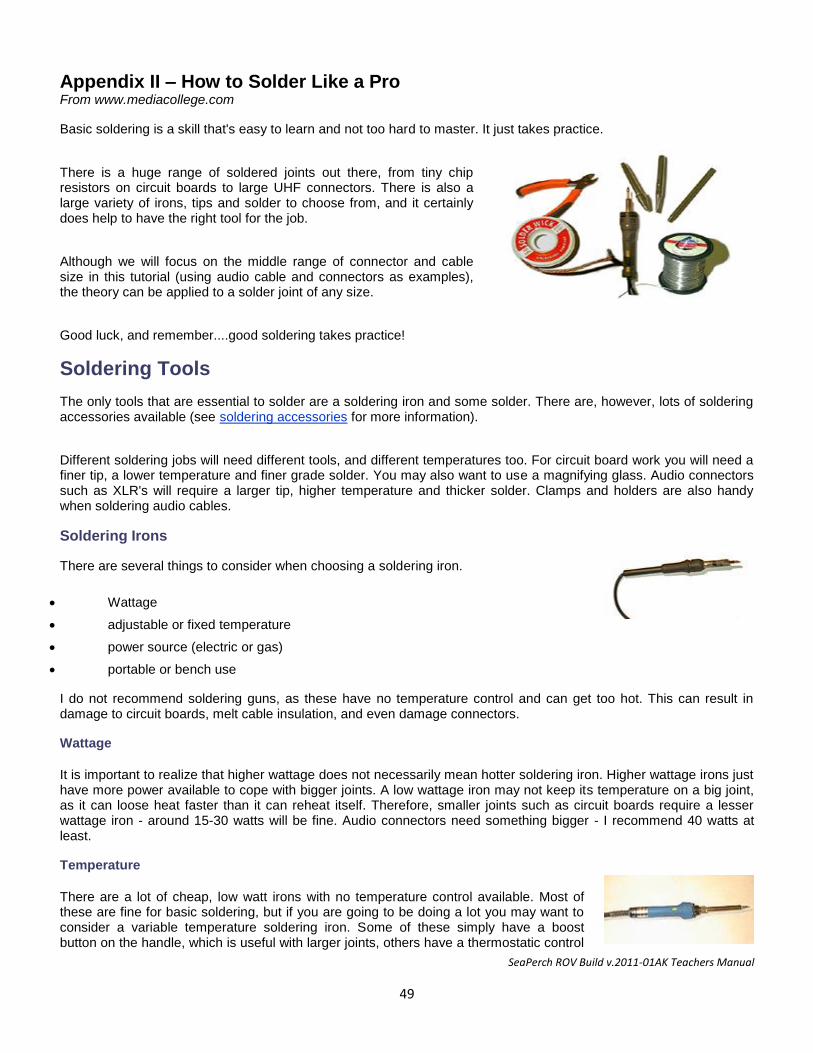
SeaPerch ROV Build v.2011-01AK Teachers Manual
49
Appendix II – How to Solder Like a Pro From www.mediacollege.com
Basic soldering is a skill that's easy to learn and not too hard to master. It just takes practice.
There is a huge range of soldered joints out there, from tiny chip resistors on circuit boards to large UHF connectors. There is also a large variety of irons, tips and solder to choose from, and it certainly does help to have the right tool for the job.
Although we will focus on the middle range of connector and cable size in this tutorial (using audio cable and connectors as examples), the theory can be applied to a solder joint of any size.
Good luck, and remember....good soldering takes practice!
Soldering Tools
The only tools that are essential to solder are a soldering iron and some solder. There are, however, lots of soldering accessories available (see soldering accessories for more information).
Different soldering jobs will need different tools, and different temperatures too. For circuit board work you will need a finer tip, a lower temperature and finer grade solder. You may also want to use a magnifying glass. Audio connectors such as XLR's will require a larger tip, higher temperature and thicker solder. Clamps and holders are also handy when soldering audio cables.
Soldering Irons
There are several things to consider when choosing a soldering iron.
Wattage
adjustable or fixed temperature
power source (electric or gas)
portable or bench use
I do not recommend soldering guns, as these have no temperature control and can get too hot. This can result in damage to circuit boards, melt cable insulation, and even damage connectors.
Wattage
It is important to realize that higher wattage does not necessarily mean hotter soldering iron. Higher wattage irons just have more power available to cope with bigger joints. A low wattage iron may not keep its temperature on a big joint, as it can loose heat faster than it can reheat itself. Therefore, smaller joints such as circuit boards require a lesser wattage iron - around 15-30 watts will be fine. Audio connectors need something bigger - I recommend 40 watts at least.
Temperature
There are a lot of cheap, low watt irons with no temperature control available. Most of these are fine for basic soldering, but if you are going to be doing a lot you may want to consider a variable temperature soldering iron. Some of these simply have a boost button on the handle, which is useful with larger joints, others have a thermostatic control
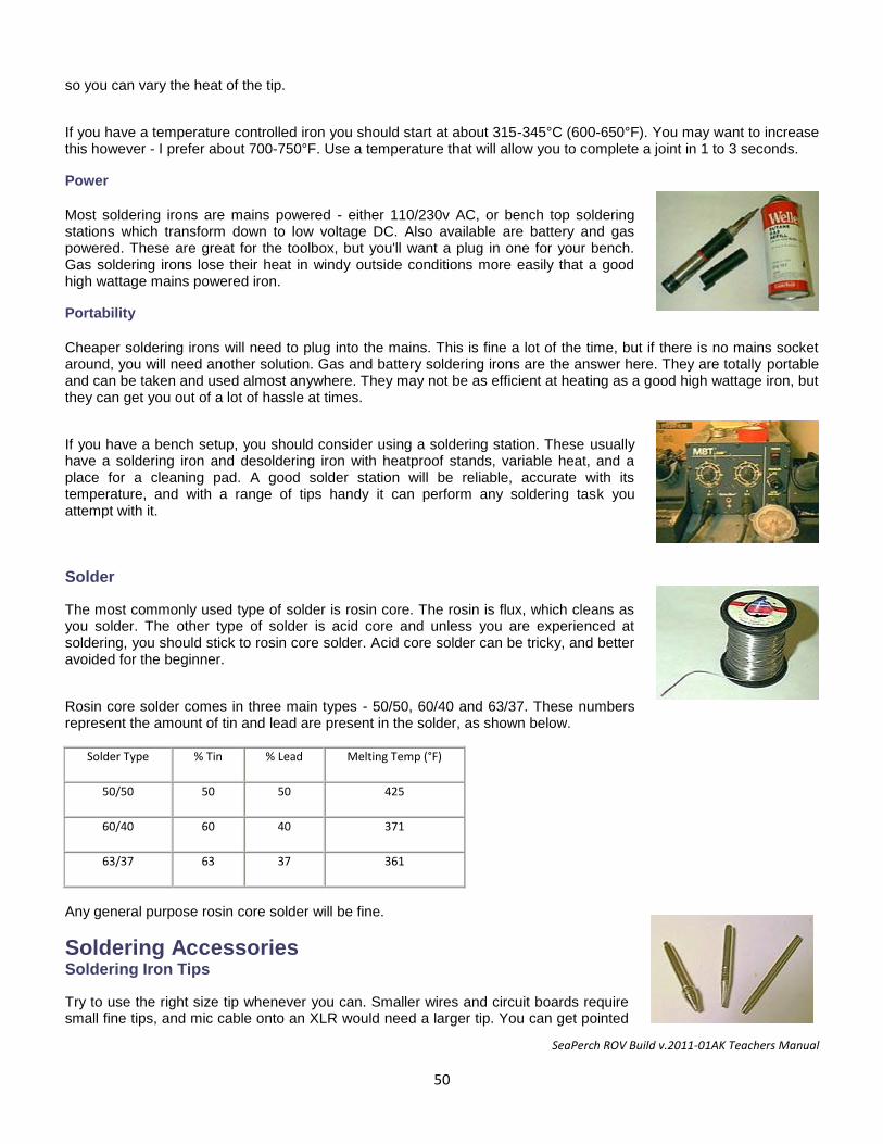
SeaPerch ROV Build v.2011-01AK Teachers Manual
50
so you can vary the heat of the tip.
If you have a temperature controlled iron you should start at about 315-345°C (600-650°F). You may want to increase this however - I prefer about 700-750°F. Use a temperature that will allow you to complete a joint in 1 to 3 seconds.
Power
Most soldering irons are mains powered - either 110/230v AC, or bench top soldering stations which transform down to low voltage DC. Also available are battery and gas powered. These are great for the toolbox, but you'll want a plug in one for your bench. Gas soldering irons lose their heat in windy outside conditions more easily that a good high wattage mains powered iron.
Portability
Cheaper soldering irons will need to plug into the mains. This is fine a lot of the time, but if there is no mains socket around, you will need another solution. Gas and battery soldering irons are the answer here. They are totally portable and can be taken and used almost anywhere. They may not be as efficient at heating as a good high wattage iron, but they can get you out of a lot of hassle at times.
If you have a bench setup, you should consider using a soldering station. These usually have a soldering iron and desoldering iron with heatproof stands, variable heat, and a place for a cleaning pad. A good solder station will be reliable, accurate with its temperature, and with a range of tips handy it can perform any soldering task you attempt with it.
Solder
The most commonly used type of solder is rosin core. The rosin is flux, which cleans as you solder. The other type of solder is acid core and unless you are experienced at soldering, you should stick to rosin core solder. Acid core solder can be tricky, and better avoided for the beginner.
Rosin core solder comes in three main types - 50/50, 60/40 and 63/37. These numbers represent the amount of tin and lead are present in the solder, as shown below.
Solder Type % Tin % Lead Melting Temp (°F)
50/50 50 50 425
60/40 60 40 371
63/37 63 37 361
Any general purpose rosin core solder will be fine.
Soldering Accessories Soldering Iron Tips
Try to use the right size tip whenever you can. Smaller wires and circuit boards require small fine tips, and mic cable onto an XLR would need a larger tip. You can get pointed
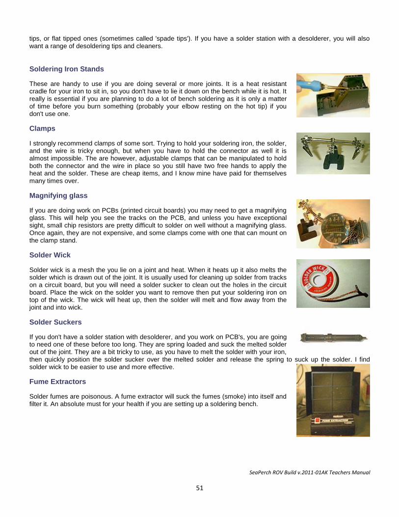
SeaPerch ROV Build v.2011-01AK Teachers Manual
51
tips, or flat tipped ones (sometimes called 'spade tips'). If you have a solder station with a desolderer, you will also want a range of desoldering tips and cleaners.
Soldering Iron Stands
These are handy to use if you are doing several or more joints. It is a heat resistant cradle for your iron to sit in, so you don't have to lie it down on the bench while it is hot. It really is essential if you are planning to do a lot of bench soldering as it is only a matter of time before you burn something (probably your elbow resting on the hot tip) if you don't use one.
Clamps
I strongly recommend clamps of some sort. Trying to hold your soldering iron, the solder, and the wire is tricky enough, but when you have to hold the connector as well it is almost impossible. The are however, adjustable clamps that can be manipulated to hold both the connector and the wire in place so you still have two free hands to apply the heat and the solder. These are cheap items, and I know mine have paid for themselves many times over.
Magnifying glass
If you are doing work on PCBs (printed circuit boards) you may need to get a magnifying glass. This will help you see the tracks on the PCB, and unless you have exceptional sight, small chip resistors are pretty difficult to solder on well without a magnifying glass. Once again, they are not expensive, and some clamps come with one that can mount on the clamp stand.
Solder Wick
Solder wick is a mesh the you lie on a joint and heat. When it heats up it also melts the solder which is drawn out of the joint. It is usually used for cleaning up solder from tracks on a circuit board, but you will need a solder sucker to clean out the holes in the circuit board. Place the wick on the solder you want to remove then put your soldering iron on top of the wick. The wick will heat up, then the solder will melt and flow away from the joint and into wick.
Solder Suckers
If you don't have a solder station with desolderer, and you work on PCB's, you are going to need one of these before too long. They are spring loaded and suck the melted solder out of the joint. They are a bit tricky to use, as you have to melt the solder with your iron, then quickly position the solder sucker over the melted solder and release the spring to suck up the solder. I find solder wick to be easier to use and more effective.
Fume Extractors
Solder fumes are poisonous. A fume extractor will suck the fumes (smoke) into itself and filter it. An absolute must for your health if you are setting up a soldering bench.
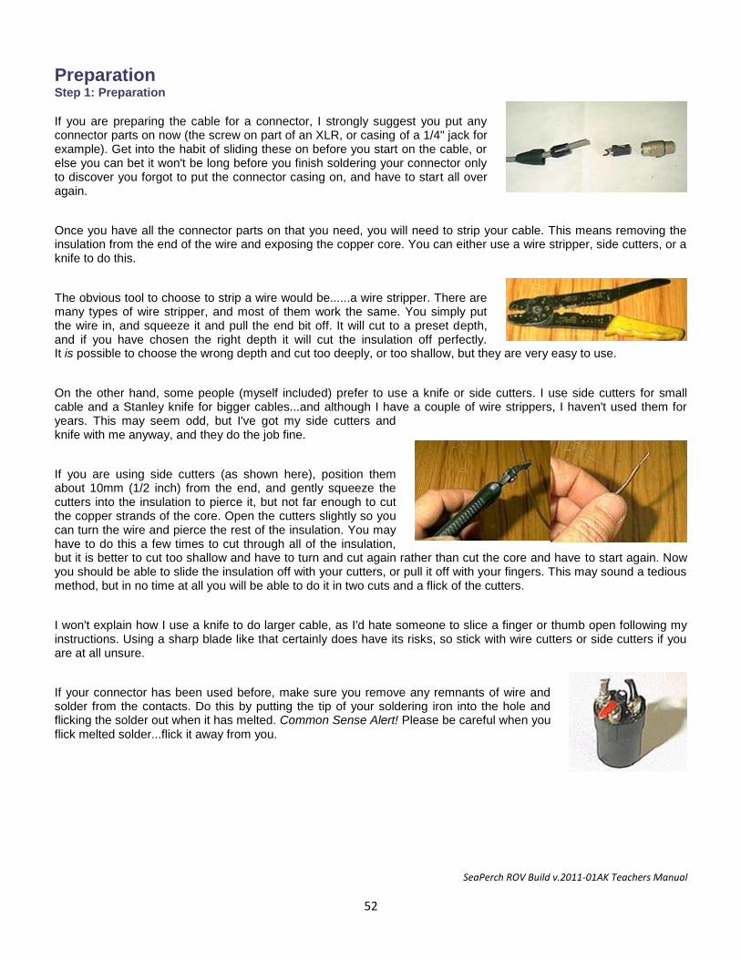
SeaPerch ROV Build v.2011-01AK Teachers Manual
52
Preparation Step 1: Preparation
If you are preparing the cable for a connector, I strongly suggest you put any connector parts on now (the screw on part of an XLR, or casing of a 1/4" jack for example). Get into the habit of sliding these on before you start on the cable, or else you can bet it won't be long before you finish soldering your connector only to discover you forgot to put the connector casing on, and have to start all over again.
Once you have all the connector parts on that you need, you will need to strip your cable. This means removing the insulation from the end of the wire and exposing the copper core. You can either use a wire stripper, side cutters, or a knife to do this.
The obvious tool to choose to strip a wire would be......a wire stripper. There are many types of wire stripper, and most of them work the same. You simply put the wire in, and squeeze it and pull the end bit off. It will cut to a preset depth, and if you have chosen the right depth it will cut the insulation off perfectly. It is possible to choose the wrong depth and cut too deeply, or too shallow, but they are very easy to use.
On the other hand, some people (myself included) prefer to use a knife or side cutters. I use side cutters for small cable and a Stanley knife for bigger cables...and although I have a couple of wire strippers, I haven't used them for years. This may seem odd, but I've got my side cutters and knife with me anyway, and they do the job fine.
If you are using side cutters (as shown here), position them about 10mm (1/2 inch) from the end, and gently squeeze the cutters into the insulation to pierce it, but not far enough to cut the copper strands of the core. Open the cutters slightly so you can turn the wire and pierce the rest of the insulation. You may have to do this a few times to cut through all of the insulation, but it is better to cut too shallow and have to turn and cut again rather than cut the core and have to start again. Now you should be able to slide the insulation off with your cutters, or pull it off with your fingers. This may sound a tedious method, but in no time at all you will be able to do it in two cuts and a flick of the cutters.
I won't explain how I use a knife to do larger cable, as I'd hate someone to slice a finger or thumb open following my instructions. Using a sharp blade like that certainly does have its risks, so stick with wire cutters or side cutters if you are at all unsure.
If your connector has been used before, make sure you remove any remnants of wire and solder from the contacts. Do this by putting the tip of your soldering iron into the hole and flicking the solder out when it has melted. Common Sense Alert! Please be careful when you flick melted solder...flick it away from you.
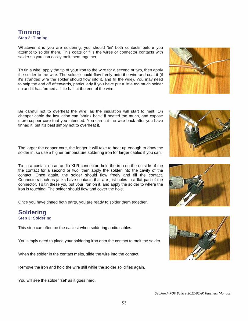
SeaPerch ROV Build v.2011-01AK Teachers Manual
53
Tinning Step 2: Tinning
Whatever it is you are soldering, you should 'tin' both contacts before you attempt to solder them. This coats or fills the wires or connector contacts with solder so you can easily melt them together.
To tin a wire, apply the tip of your iron to the wire for a second or two, then apply the solder to the wire. The solder should flow freely onto the wire and coat it (if it's stranded wire the solder should flow into it, and fill the wire). You may need to snip the end off afterwards, particularly if you have put a little too much solder on and it has formed a little ball at the end of the wire.
Be careful not to overheat the wire, as the insulation will start to melt. On cheaper cable the insulation can 'shrink back' if heated too much, and expose more copper core that you intended. You can cut the wire back after you have tinned it, but it's best simply not to overheat it.
The larger the copper core, the longer it will take to heat up enough to draw the solder in, so use a higher temperature soldering iron for larger cables if you can.
To tin a contact on an audio XLR connector, hold the iron on the outside of the the contact for a second or two, then apply the solder into the cavity of the contact. Once again, the solder should flow freely and fill the contact. Connectors such as jacks have contacts that are just holes in a flat part of the connector. To tin these you put your iron on it, and apply the solder to where the iron is touching. The solder should flow and cover the hole.
Once you have tinned both parts, you are ready to solder them together.
Soldering Step 3: Soldering
This step can often be the easiest when soldering audio cables.
You simply need to place your soldering iron onto the contact to melt the solder.
When the solder in the contact melts, slide the wire into the contact.
Remove the iron and hold the wire still while the solder solidifies again.
You will see the solder 'set' as it goes hard.
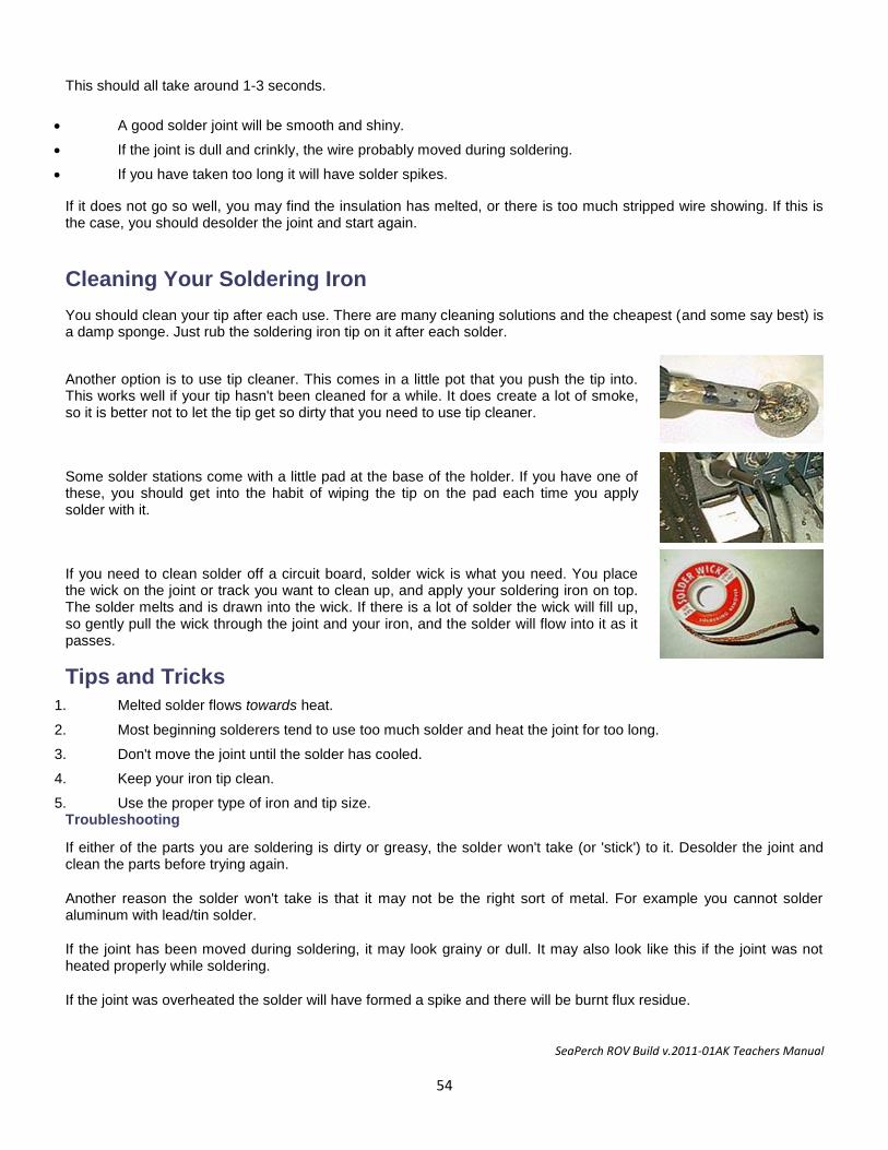
SeaPerch ROV Build v.2011-01AK Teachers Manual
54
This should all take around 1-3 seconds.
A good solder joint will be smooth and shiny.
If the joint is dull and crinkly, the wire probably moved during soldering.
If you have taken too long it will have solder spikes.
If it does not go so well, you may find the insulation has melted, or there is too much stripped wire showing. If this is the case, you should desolder the joint and start again.
Cleaning Your Soldering Iron
You should clean your tip after each use. There are many cleaning solutions and the cheapest (and some say best) is a damp sponge. Just rub the soldering iron tip on it after each solder.
Another option is to use tip cleaner. This comes in a little pot that you push the tip into. This works well if your tip hasn't been cleaned for a while. It does create a lot of smoke, so it is better not to let the tip get so dirty that you need to use tip cleaner.
Some solder stations come with a little pad at the base of the holder. If you have one of these, you should get into the habit of wiping the tip on the pad each time you apply solder with it.
If you need to clean solder off a circuit board, solder wick is what you need. You place the wick on the joint or track you want to clean up, and apply your soldering iron on top. The solder melts and is drawn into the wick. If there is a lot of solder the wick will fill up, so gently pull the wick through the joint and your iron, and the solder will flow into it as it passes.
Tips and Tricks
1. Melted solder flows towards heat.
2. Most beginning solderers tend to use too much solder and heat the joint for too long.
3. Don't move the joint until the solder has cooled.
4. Keep your iron tip clean.
5. Use the proper type of iron and tip size. Troubleshooting
If either of the parts you are soldering is dirty or greasy, the solder won't take (or 'stick') to it. Desolder the joint and clean the parts before trying again.
Another reason the solder won't take is that it may not be the right sort of metal. For example you cannot solder aluminum with lead/tin solder.
If the joint has been moved during soldering, it may look grainy or dull. It may also look like this if the joint was not heated properly while soldering.
If the joint was overheated the solder will have formed a spike and there will be burnt flux residue.
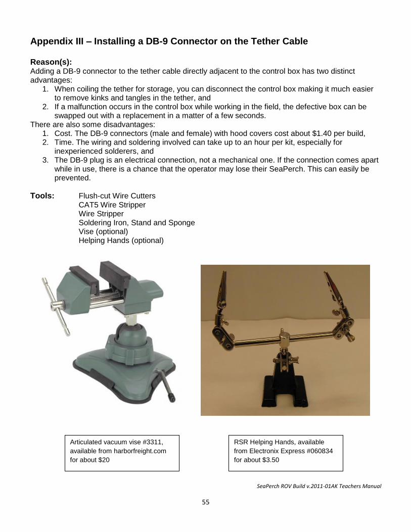
SeaPerch ROV Build v.2011-01AK Teachers Manual
55
Articulated vacuum vise #3311,
available from harborfreight.com
for about $20
RSR Helping Hands, available
from Electronix Express #060834
for about $3.50
Appendix III – Installing a DB-9 Connector on the Tether Cable Reason(s): Adding a DB-9 connector to the tether cable directly adjacent to the control box has two distinct advantages:
1. When coiling the tether for storage, you can disconnect the control box making it much easier to remove kinks and tangles in the tether, and
2. If a malfunction occurs in the control box while working in the field, the defective box can be swapped out with a replacement in a matter of a few seconds.
There are also some disadvantages: 1. Cost. The DB-9 connectors (male and female) with hood covers cost about $1.40 per build, 2. Time. The wiring and soldering involved can take up to an hour per kit, especially for
inexperienced solderers, and 3. The DB-9 plug is an electrical connection, not a mechanical one. If the connection comes apart
while in use, there is a chance that the operator may lose their SeaPerch. This can easily be prevented.
Tools: Flush-cut Wire Cutters CAT5 Wire Stripper Wire Stripper Soldering Iron, Stand and Sponge Vise (optional) Helping Hands (optional)
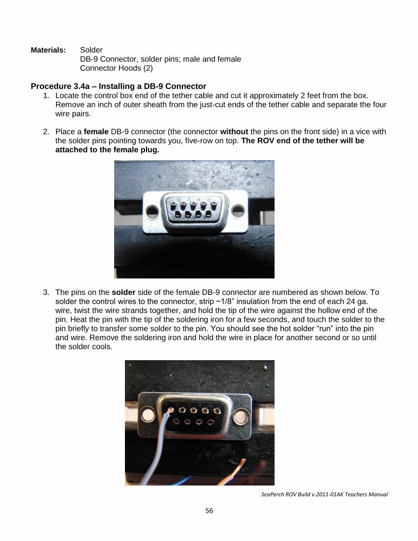
SeaPerch ROV Build v.2011-01AK Teachers Manual
56
Materials: Solder DB-9 Connector, solder pins; male and female Connector Hoods (2)
Procedure 3.4a – Installing a DB-9 Connector 1. Locate the control box end of the tether cable and cut it approximately 2 feet from the box.
Remove an inch of outer sheath from the just-cut ends of the tether cable and separate the four wire pairs.
2. Place a female DB-9 connector (the connector without the pins on the front side) in a vice with the solder pins pointing towards you, five-row on top. The ROV end of the tether will be attached to the female plug.
3. The pins on the solder side of the female DB-9 connector are numbered as shown below. To
solder the control wires to the connector, strip ~1/8” insulation from the end of each 24 ga. wire, twist the wire strands together, and hold the tip of the wire against the hollow end of the pin. Heat the pin with the tip of the soldering iron for a few seconds, and touch the solder to the pin briefly to transfer some solder to the pin. You should see the hot solder “run” into the pin and wire. Remove the soldering iron and hold the wire in place for another second or so until the solder cools.
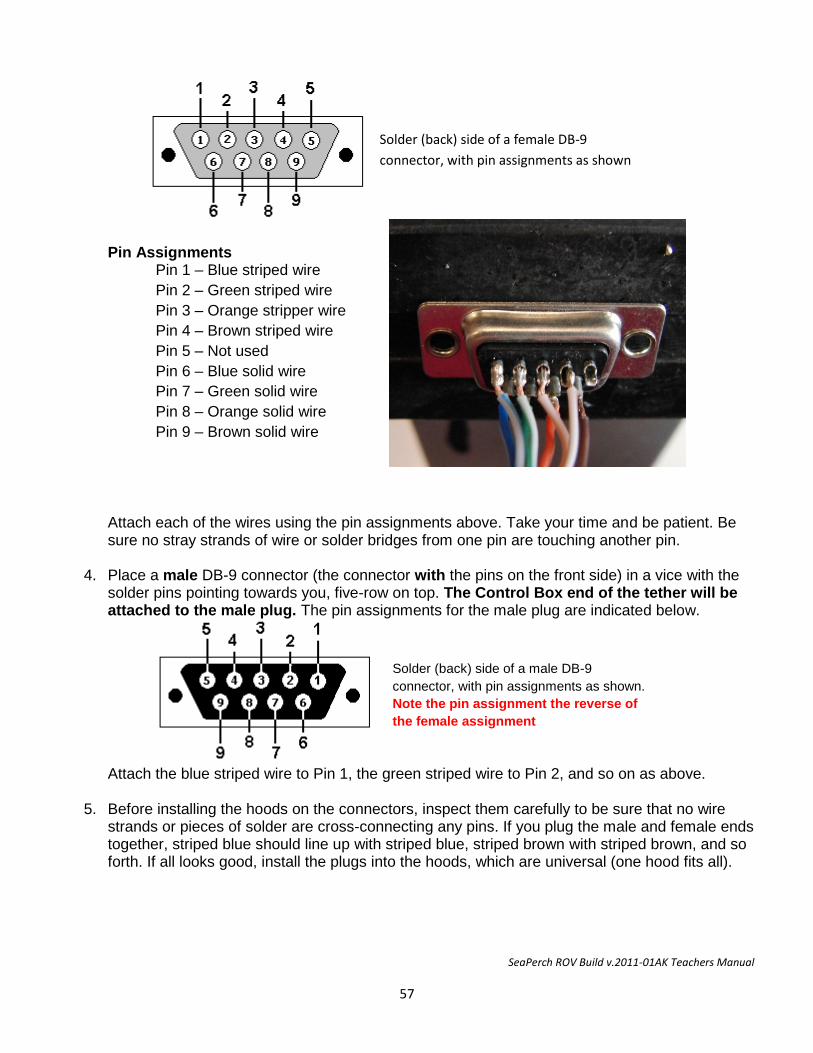
SeaPerch ROV Build v.2011-01AK Teachers Manual
57
Solder (back) side of a female DB-9
connector, with pin assignments as shown
Solder (back) side of a male DB-9
connector, with pin assignments as shown.
Note the pin assignment the reverse of
the female assignment
Pin Assignments Pin 1 – Blue striped wire
Pin 2 – Green striped wire
Pin 3 – Orange stripper wire
Pin 4 – Brown striped wire
Pin 5 – Not used
Pin 6 – Blue solid wire
Pin 7 – Green solid wire
Pin 8 – Orange solid wire
Pin 9 – Brown solid wire
Attach each of the wires using the pin assignments above. Take your time and be patient. Be sure no stray strands of wire or solder bridges from one pin are touching another pin.
4. Place a male DB-9 connector (the connector with the pins on the front side) in a vice with the solder pins pointing towards you, five-row on top. The Control Box end of the tether will be attached to the male plug. The pin assignments for the male plug are indicated below.
Attach the blue striped wire to Pin 1, the green striped wire to Pin 2, and so on as above.
5. Before installing the hoods on the connectors, inspect them carefully to be sure that no wire strands or pieces of solder are cross-connecting any pins. If you plug the male and female ends together, striped blue should line up with striped blue, striped brown with striped brown, and so forth. If all looks good, install the plugs into the hoods, which are universal (one hood fits all).
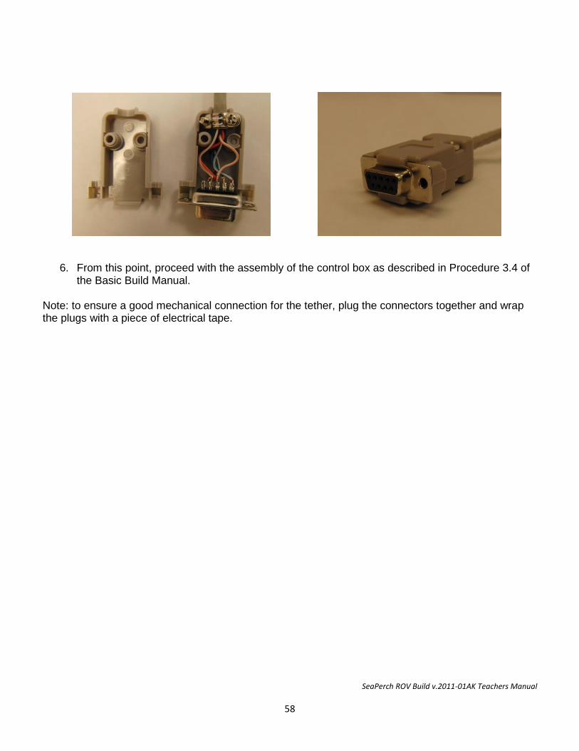
SeaPerch ROV Build v.2011-01AK Teachers Manual
58
6. From this point, proceed with the assembly of the control box as described in Procedure 3.4 of the Basic Build Manual.
Note: to ensure a good mechanical connection for the tether, plug the connectors together and wrap the plugs with a piece of electrical tape.
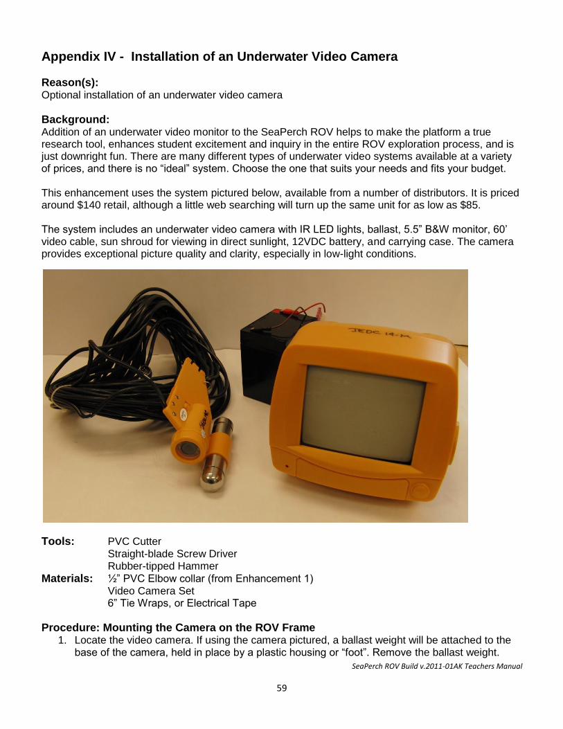
SeaPerch ROV Build v.2011-01AK Teachers Manual
59
Appendix IV - Installation of an Underwater Video Camera
Reason(s): Optional installation of an underwater video camera
Background: Addition of an underwater video monitor to the SeaPerch ROV helps to make the platform a true research tool, enhances student excitement and inquiry in the entire ROV exploration process, and is just downright fun. There are many different types of underwater video systems available at a variety of prices, and there is no “ideal” system. Choose the one that suits your needs and fits your budget. This enhancement uses the system pictured below, available from a number of distributors. It is priced around $140 retail, although a little web searching will turn up the same unit for as low as $85. The system includes an underwater video camera with IR LED lights, ballast, 5.5” B&W monitor, 60’ video cable, sun shroud for viewing in direct sunlight, 12VDC battery, and carrying case. The camera provides exceptional picture quality and clarity, especially in low-light conditions.
Tools: PVC Cutter Straight-blade Screw Driver Rubber-tipped Hammer
Materials: ½” PVC Elbow collar (from Enhancement 1) Video Camera Set 6” Tie Wraps, or Electrical Tape
Procedure: Mounting the Camera on the ROV Frame 1. Locate the video camera. If using the camera pictured, a ballast weight will be attached to the
base of the camera, held in place by a plastic housing or “foot”. Remove the ballast weight.
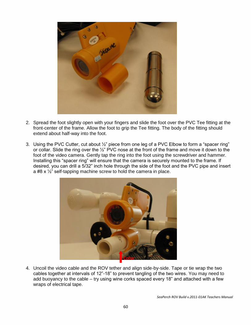
SeaPerch ROV Build v.2011-01AK Teachers Manual
60
Collar
2. Spread the foot slightly open with your fingers and slide the foot over the PVC Tee fitting at the
front-center of the frame. Allow the foot to grip the Tee fitting. The body of the fitting should extend about half-way into the foot.
3. Using the PVC Cutter, cut about ½” piece from one leg of a PVC Elbow to form a “spacer ring” or collar. Slide the ring over the ½” PVC nose at the front of the frame and move it down to the foot of the video camera. Gently tap the ring into the foot using the screwdriver and hammer. Installing this “spacer ring” will ensure that the camera is securely mounted to the frame. If desired, you can drill a 5/32” inch hole through the side of the foot and the PVC pipe and insert a #8 x ½” self-tapping machine screw to hold the camera in place.
4. Uncoil the video cable and the ROV tether and align side-by-side. Tape or tie wrap the two
cables together at intervals of 12”-18” to prevent tangling of the two wires. You may need to add buoyancy to the cable – try using wine corks spaced every 18” and attached with a few wraps of electrical tape.
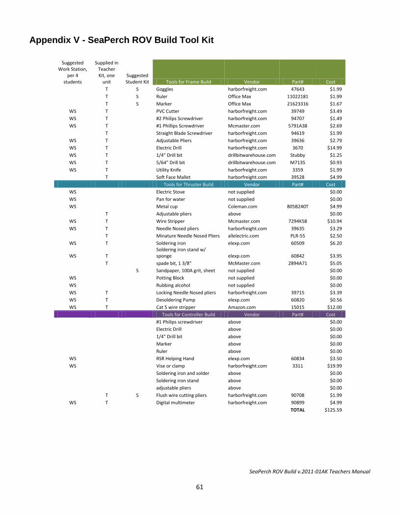
SeaPerch ROV Build v.2011-01AK Teachers Manual
61
Appendix V - SeaPerch ROV Build Tool Kit
Suggested Work Station,
per 4 students
Supplied in Teacher Kit, one
unit Suggested Student Kit Tools for Frame Build Vendor Part# Cost
T S Goggles harborfreight.com 47643 $1.99
T S Ruler Office Max 11022181 $1.99
T S Marker Office Max 21623316 $1.67
WS T
PVC Cutter harborfreight.com 39749 $3.49
WS T
#2 Philips Screwdriver harborfreight.com 94707 $1.49
WS T
#1 Phillips Screwdriver Mcmaster.com 5791A38 $2.69
T
Straight Blade Screwdriver harborfreight.com 94619 $1.99
WS T
Adjustable Pliers harborfreight.com 39636 $2.79
WS T
Electric Drill harborfreight.com 3670 $14.99
WS T
1/4" Drill bit drillbitwarehouse.com Stubby $1.25
WS T
5/64" Drill bit drillbitwarehouse.com M7135 $0.93
WS T
Utility Knife harborfreight.com 3359 $1.99
T
Soft Face Mallet harborfreight.com 39528 $4.99
Tools for Thruster Build Vendor Part# Cost
WS
Electric Stove not supplied
$0.00
WS
Pan for water not supplied
$0.00
WS
Metal cup Coleman.com 805B240T $4.99
T
Adjustable pliers above
$0.00
WS T
Wire Stripper Mcmaster.com 7294K58 $10.94
WS T
Needle Nosed pliers harborfreight.com 39635 $3.29
T
Minature Needle Nosed Pliers allelectric.com PLR-55 $2.50
WS T
Soldering iron elexp.com 60509 $6.20
WS T
Soldering iron stand w/ sponge elexp.com 60842 $3.95
T
spade bit, 1 3/8" McMaster.com 2894A71 $5.05
S Sandpaper, 100A grit, sheet not supplied
$0.00
WS
Potting Block not supplied
$0.00
WS
Rubbing alcohol not supplied
$0.00
WS T
Locking Needle Nosed pliers harborfreight.com 39715 $3.39
WS T
Desoldering Pump elexp.com 60820 $0.56
WS T
Cat 5 wire stripper Amazon.com 15015 $12.00
Tools for Controller Build Vendor Part# Cost
#1 Philips screwdriver above
$0.00
Electric Drill above
$0.00
1/4" Drill bit above
$0.00
Marker above
$0.00
Ruler above
$0.00
WS
RSR Helping Hand elexp.com 60834 $3.50
WS
Vise or clamp harborfreight.com 3311 $19.99
Soldering iron and solder above
$0.00
Soldering iron stand above
$0.00
adjustable pliers above
$0.00
T S Flush wire cutting pliers harborfreight.com 90708 $1.99
WS T
Digital multimeter harborfreight.com 90899 $4.99
TOTAL $125.59

SeaPerch ROV Build v.2011-01AK Teachers Manual
62
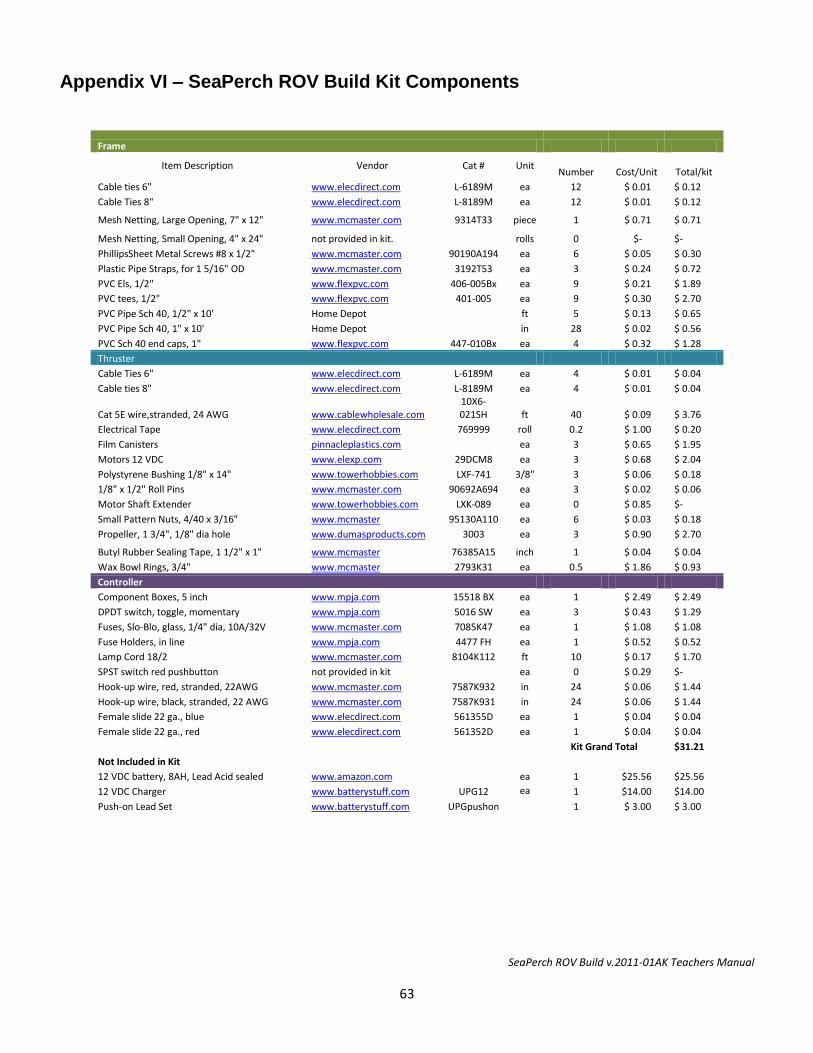
SeaPerch ROV Build v.2011-01AK Teachers Manual
63
Appendix VI – SeaPerch ROV Build Kit Components
Frame
Item Description Vendor Cat # Unit Number
Cost/Unit Total/kit
Cable ties 6" www.elecdirect.com L-6189M ea 12 $ 0.01 $ 0.12
Cable Ties 8" www.elecdirect.com L-8189M ea 12 $ 0.01 $ 0.12
Mesh Netting, Large Opening, 7" x 12" www.mcmaster.com 9314T33 piece 1 $ 0.71 $ 0.71
Mesh Netting, Small Opening, 4" x 24" not provided in kit.
rolls 0 $- $-
PhillipsSheet Metal Screws #8 x 1/2" www.mcmaster.com 90190A194 ea 6 $ 0.05 $ 0.30
Plastic Pipe Straps, for 1 5/16" OD www.mcmaster.com 3192T53 ea 3 $ 0.24 $ 0.72
PVC Els, 1/2" www.flexpvc.com 406-005Bx ea 9 $ 0.21 $ 1.89
PVC tees, 1/2" www.flexpvc.com 401-005 ea 9 $ 0.30 $ 2.70
PVC Pipe Sch 40, 1/2" x 10' Home Depot
ft 5 $ 0.13 $ 0.65
PVC Pipe Sch 40, 1" x 10' Home Depot
in 28 $ 0.02 $ 0.56
PVC Sch 40 end caps, 1" www.flexpvc.com 447-010Bx ea 4 $ 0.32 $ 1.28
Thruster
Cable Ties 6" www.elecdirect.com L-6189M ea 4 $ 0.01 $ 0.04
Cable ties 8" www.elecdirect.com L-8189M ea 4 $ 0.01 $ 0.04
Cat 5E wire,stranded, 24 AWG www.cablewholesale.com
10X6-021SH ft 40 $ 0.09 $ 3.76
Electrical Tape www.elecdirect.com 769999 roll 0.2 $ 1.00 $ 0.20
Film Canisters pinnacleplastics.com
ea 3 $ 0.65 $ 1.95
Motors 12 VDC www.elexp.com 29DCM8 ea 3 $ 0.68 $ 2.04
Polystyrene Bushing 1/8" x 14" www.towerhobbies.com LXF-741 3/8" 3 $ 0.06 $ 0.18
1/8" x 1/2" Roll Pins www.mcmaster.com 90692A694 ea 3 $ 0.02 $ 0.06
Motor Shaft Extender www.towerhobbies.com LXK-089 ea 0 $ 0.85 $-
Small Pattern Nuts, 4/40 x 3/16" www.mcmaster 95130A110 ea 6 $ 0.03 $ 0.18
Propeller, 1 3/4", 1/8" dia hole www.dumasproducts.com 3003 ea 3 $ 0.90 $ 2.70
Butyl Rubber Sealing Tape, 1 1/2" x 1" www.mcmaster 76385A15 inch 1 $ 0.04 $ 0.04
Wax Bowl Rings, 3/4" www.mcmaster 2793K31 ea 0.5 $ 1.86 $ 0.93
Controller
Component Boxes, 5 inch www.mpja.com 15518 BX ea 1 $ 2.49 $ 2.49
DPDT switch, toggle, momentary www.mpja.com 5016 SW ea 3 $ 0.43 $ 1.29
Fuses, Slo-Blo, glass, 1/4" dia, 10A/32V www.mcmaster.com 7085K47 ea 1 $ 1.08 $ 1.08
Fuse Holders, in line www.mpja.com 4477 FH ea 1 $ 0.52 $ 0.52
Lamp Cord 18/2 www.mcmaster.com 8104K112 ft 10 $ 0.17 $ 1.70
SPST switch red pushbutton not provided in kit
ea 0 $ 0.29 $-
Hook-up wire, red, stranded, 22AWG www.mcmaster.com 7587K932 in 24 $ 0.06 $ 1.44
Hook-up wire, black, stranded, 22 AWG www.mcmaster.com 7587K931 in 24 $ 0.06 $ 1.44
Female slide 22 ga., blue www.elecdirect.com 561355D ea 1 $ 0.04 $ 0.04
Female slide 22 ga., red www.elecdirect.com 561352D ea 1 $ 0.04 $ 0.04
Kit Grand Total $31.21
Not Included in Kit 12 VDC battery, 8AH, Lead Acid sealed www.amazon.com
ea 1 $25.56 $25.56
12 VDC Charger www.batterystuff.com UPG12 ea 1 $14.00 $14.00
Push-on Lead Set www.batterystuff.com UPGpushon
1
$ 3.00 $ 3.00


![REMOTELY OPERATED VEHICLE [ MINI-ROV ] …€¦ · REMOTELY OPERATED VEHICLE [ MINI-ROV ]ELECTRICAL MANIPULATOR ARM UNDERWATER INSPECTION & OPERATION UP TO 300 METER DEEP Targeted](https://static.fdocuments.net/doc/165x107/5ac8cc3b7f8b9a7d548ca5ff/remotely-operated-vehicle-mini-rov-remotely-operated-vehicle-mini-rov.jpg)