Remote Fire Annunciator LCD-2X20 Series - Fire Alarm … · Remote Fire Annunciator LCD-2X20 Series...
36
Document 51105 7/25/00 Rev: B PN:51105:B ECN 00-325 Remote Fire Annunciator LCD-2X20 Series www.PDF-Zoo.com
Transcript of Remote Fire Annunciator LCD-2X20 Series - Fire Alarm … · Remote Fire Annunciator LCD-2X20 Series...

Document 511057/25/00 Rev: B
PN:51105:B ECN 00-325
RemoteFire Annunciator
LCD-2X20 Series
www.PDF-Zoo.com
LimWarSm.p65 01/10/2000
An automatic fire alarm system–typically made up ofsmoke detectors, heat detectors, manual pull stations,audible warning devices, and a fire alarm control withremote notification capability–can provide early warningof a developing fire. Such a system, however, does notassure protection against property damage or loss of liferesulting from a fire.
The Manufacturer recommends that smoke and/or heatdetectors be located throughout a protected premisefollowing the recommendations of the current edition ofthe National Fire Protection Association Standard 72(NFPA 72), manufacturer's recommendations, State andlocal codes, and the recommendations contained in theGuide for Proper Use of System Smoke Detectors, whichis made available at no charge to all installing dealers.A study by the Federal Emergency Management Agency(an agency of the United States government) indicatedthat smoke detectors may not go off in as many as 35%of all fires. While fire alarm systems are designed toprovide early warning against fire, they do not guaranteewarning or protection against fire. A fire alarm systemmay not provide timely or adequate warning, or simplymay not function, for a variety of reasons:
Smoke detectors may not sense fire where smokecannot reach the detectors such as in chimneys, in orbehind walls, on roofs, or on the other side of closeddoors. Smoke detectors also may not sense a fire onanother level or floor of a building. A second-floordetector, for example, may not sense a first-floor orbasement fire.
Particles of combustion or "smoke" from a developingfire may not reach the sensing chambers of smokedetectors because:
• Barriers such as closed or partially closed doors,walls, or chimneys may inhibit particle or smoke flow.
• Smoke particles may become "cold," stratify, and notreach the ceiling or upper walls where detectors arelocated.
• Smoke particles may be blown away from detectorsby air outlets.
• Smoke detectors may be drawn into air returns beforereaching the detector.
The amount of "smoke" present may be insufficient toalarm smoke detectors. Smoke detectors are designedto alarm at various levels of smoke density. If suchdensity levels are not created by a developing fire at thelocation of detectors, the detectors will not go into alarm.
Smoke detectors, even when working properly, havesensing limitations. Detectors that have photoelectronicsensing chambers tend to detect smoldering fires betterthan flaming fires, which have little visible smoke.Detectors that have ionizing-type sensing chamberstend to detect fast-flaming fires better than smolderingfires. Because fires develop in different ways and areoften unpredictable in their growth, neither type of detec-tor is necessarily best and a given type of detector maynot provide adequate warning of a fire.
Smoke detectors cannot be expected to provideadequate warning of fires caused by arson, childrenplaying with matches (especially in bedrooms), smokingin bed, and violent explosions (caused by escaping gas,improper storage of flammable materials, etc.).
Heat detectors do not sense particles of combustion andalarm only when heat on their sensors increases at apredetermined rate or reaches a predetermined level.Rate-of-rise heat detectors may be subject to reducedsensitivity over time. For this reason, the rate-of-risefeature of each detector should be tested at least onceper year by a qualified fire protection specialist. Heatdetectors are designed to protect property, not life.
IMPORTANT! Smoke detectors must be installed inthe same room as the control panel and in rooms usedby the system for the connection of alarm transmissionwiring, communications, signaling, and/or power. Ifdetectors are not so located, a developing fire may dam-age the alarm system, crippling its ability to report a fire.
Audible warning devices such as bells may not alertpeople if these devices are located on the other side ofclosed or partly open doors or are located on anotherfloor of a building. Any warning device may fail to alertpeople with a disability or those who have recently con-sumed drugs, alcohol or medication. Please note that:
• Strobes can, under certain circumstances, causeseizures in people with conditions such as epilepsy.
• Studies have shown that certain people, even whenthey hear a fire alarm signal, do not respond orcomprehend the meaning of the signal. It is theproperty owner's responsibility to conduct fire drillsand other training exercise to make people aware offire alarm signals and instruct them on the properreaction to alarm signals.
• In rare instances, the sounding of a warning devicecan cause temporary or permanent hearing loss.
A fire alarm system will not operate without anyelectrical power. If AC power fails, the system willoperate from standby batteries only for a specified timeand only if the batteries have been properly maintainedand replaced regularly.
Equipment used in the system may not be technicallycompatible with the control. It is essential to use onlyequipment listed for service with your control panel.
Telephone lines needed to transmit alarm signals froma premise to a central monitoring station may be out ofservice or temporarily disabled. For added protectionagainst telephone line failure, backup radio transmissionsystems are recommended.
The most common cause of fire alarm malfunction isinadequate maintenance. To keep the entire fire alarmsystem in excellent working order, ongoing maintenanceis required per the manufacturer's recommendations,and UL and NFPA standards. At a minimum, therequirements of Chapter 7 of NFPA 72 shall be followed.Environments with large amounts of dust, dirt or high airvelocity require more frequent maintenance. A mainte-nance agreement should be arranged through the localmanufacturer's representative. Maintenance should bescheduled monthly or as required by National and/orlocal fire codes and should be performed by authorizedprofessional fire alarm installers only. Adequate writtenrecords of all inspections should be kept.
While a fire alarm system may lower insurance
rates, it is not a substitute for fire insurance!Fire Alarm System Limitations
www.PDF-Zoo.com

LimWarSm.p65 01/10/2000
WARNING - Several different sources of power can beconnected to the fire alarm control panel. Disconnect allsources of power before servicing. Control unit andassociated equipment may be damaged by removingand/or inserting cards, modules, or interconnectingcables while the unit is energized. Do not attempt toinstall, service, or operate this unit until this manual isread and understood.
CAUTION - System Reacceptance Test after SoftwareChanges. To ensure proper system operation, thisproduct must be tested in accordance with NFPA 72Chapter 7 after any programming operation or change insite-specific software. Reacceptance testing is requiredafter any change, addition or deletion of system compo-nents, or after any modification, repair or adjustment tosystem hardware or wiring.
All components, circuits, system operations, or softwarefunctions known to be affected by a change must be100% tested. In addition, to ensure that other operationsare not inadvertently affected, at least 10% of initiatingdevices that are not directly affected by the change, upto a maximum of 50 devices, must also be tested andproper system operation verified.
This system meets NFPA requirements for operationat 0-49° C/32-120° F and at a relative humidity of 85%RH (non-condensing) at 30° C/86° F. However, theuseful life of the system's standby batteries and theelectronic components may be adversely affected byextreme temperature ranges and humidity. Therefore,it is recommended that this system and all peripheralsbe installed in an environment with a nominal roomtemperature of 15-27° C/60-80° F.
Verify that wire sizes are adequate for all initiating andindicating device loops. Most devices cannot toleratemore than a 10% I.R. drop from the specified devicevoltage.
Like all solid state electronic devices, this system mayoperate erratically or can be damaged when subjectedto lightning-induced transients. Although no system iscompletely immune from lightning transients and inter-ferences, proper grounding will reduce susceptibility.Overhead or outside aerial wiring is not recommended,due to an increased susceptibility to nearby lightningstrikes. Consult with the Technical Services Departmentif any problems are anticipated or encountered.
Disconnect AC power and batteries prior to removingor inserting circuit boards. Failure to do so can damagecircuits.
Remove all electronic assemblies prior to any drilling,filing, reaming, or punching of the enclosure. Whenpossible, make all cable entries from the sides or rear.Before making modifications, verify that they will notinterfere with battery, transformer, and printed circuitboard location.
Do not tighten screw terminals more than 9 in-lbs.Over-tightening may damage threads, resulting inreduced terminal contact pressure and difficulty withscrew terminal removal.
Though designed to last many years, system compo-nents can fail at any time. This system contains static-sensitive components. Always ground yourself with aproper wrist strap before handling any circuits so thatstatic charges are removed from the body. Use static-suppressive packaging to protect electronic assembliesremoved from the unit.
Follow the instructions in the installation, operating,and programming manuals. These instructions mustbe followed to avoid damage to the control panel andassociated equipment. FACP operation and reliabilitydepend upon proper installation by authorized personnel.
WARNING: This equipment generates, uses, andcan radiate radio frequency energy and if not in-stalled and used in accordance with the instructionmanual, may cause interference to radio commu-nications. It has been tested and found to complywith the limits for class A computing device pursu-ant to Subpart B of Part 15 of FCC Rules, which isdesigned to provide reasonable protection againstsuch interference when operated in a commercialenvironment. Operation of this equipment in aresidential area is likely to cause interference, inwhich case the user will be required to correct theinterference at his own expense.
Canadian RequirementsThis digital apparatus does not exceed theClass A limits for radiation noise emissions fromdigital apparatus set out in the Radio Interfer-ence Regulations of the Canadian Departmentof Communications.
Le present appareil numerique n'emet pas debruits radioelectriques depassant les limitesapplicables aux appareils numeriques de laclasse A prescrites dans le Reglement sur lebrouillage radioelectrique edicte par leministere des Communications du Canada.
FCC Warning
Adherence to the following will aid in problem-freeinstallation with long-term reliability:Installation Precautions
www.PDF-Zoo.com

4 Document 51105 Rev B 7/25/00 P/N 51105:B
Notes
www.PDF-Zoo.com
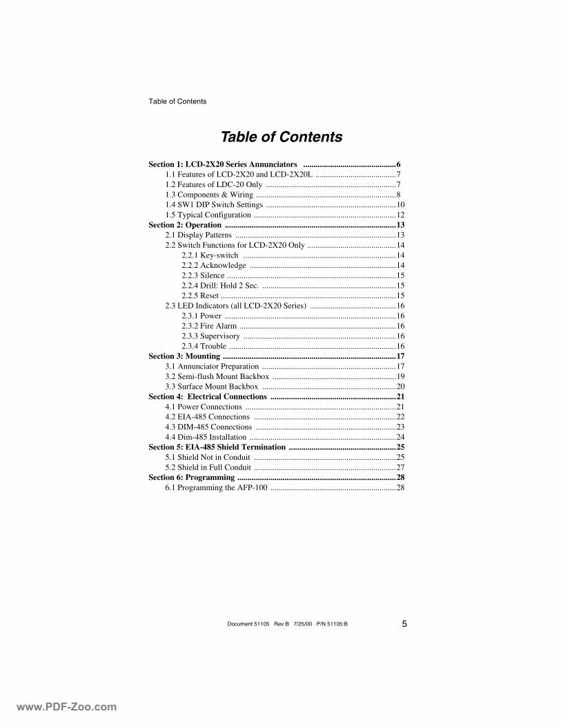
Table of Contents
5Document 51105 Rev B 7/25/00 P/N 51105:B
Table of Contents
Section 1: LCD-2X20 Series Annunciators .............................................61.1 Features of LCD-2X20 and LCD-2X20L .......................................71.2 Features of LDC-20 Only ...............................................................71.3 Components & Wiring ....................................................................81.4 SW1 DIP Switch Settings ...............................................................101.5 Typical Configuration .....................................................................12
Section 2: Operation ...................................................................................132.1 Display Patterns ..............................................................................132.2 Switch Functions for LCD-2X20 Only ...........................................14
2.2.1 Key-switch ..........................................................................142.2.2 Acknowledge .......................................................................142.2.3 Silence ..................................................................................152.2.4 Drill: Hold 2 Sec. .................................................................152.2.5 Reset .....................................................................................15
2.3 LED Indicators (all LCD-2X20 Series) ..........................................162.3.1 Power ...................................................................................162.3.2 Fire Alarm ............................................................................162.3.3 Supervisory ..........................................................................162.3.4 Trouble .................................................................................16
Section 3: Mounting ....................................................................................173.1 Annunciator Preparation .................................................................173.2 Semi-flush Mount Backbox ............................................................193.3 Surface Mount Backbox .................................................................20
Section 4: Electrical Connections .............................................................214.1 Power Connections .........................................................................214.2 EIA-485 Connections .....................................................................224.3 DIM-485 Connections ....................................................................234.4 Dim-485 Installation .......................................................................24
Section 5: EIA-485 Shield Termination ....................................................255.1 Shield Not in Conduit .....................................................................255.2 Shield in Full Conduit .....................................................................27
Section 6: Programming .............................................................................286.1 Programming the AFP-100 .............................................................28
www.PDF-Zoo.com
LCD-2X20 Series Annunciators
6 Document 51105 Rev B 7/25/00 P/N 51105:B
Section 1: LCD-2X20 Series Annunciators
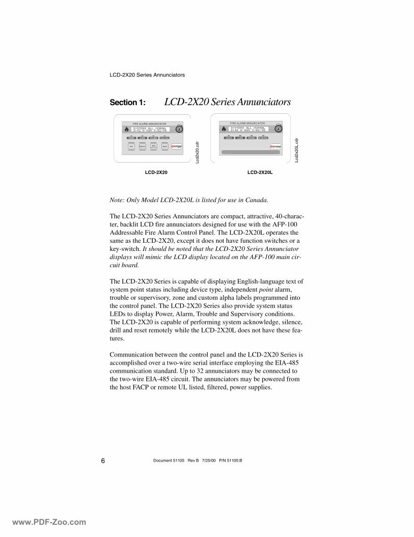
Note: Only Model LCD-2X20L is listed for use in Canada.
The LCD-2X20 Series Annunciators are compact, attractive, 40-charac-ter, backlit LCD fire annunciators designed for use with the AFP-100 Addressable Fire Alarm Control Panel. The LCD-2X20L operates the same as the LCD-2X20, except it does not have function switches or a key-switch. It should be noted that the LCD-2X20 Series Annunciator displays will mimic the LCD display located on the AFP-100 main cir-cuit board.
The LCD-2X20 Series is capable of displaying English-language text of system point status including device type, independent point alarm, trouble or supervisory, zone and custom alpha labels programmed into the control panel. The LCD-2X20 Series also provide system status LEDs to display Power, Alarm, Trouble and Supervisory conditions. The LCD-2X20 is capable of performing system acknowledge, silence, drill and reset remotely while the LCD-2X20L does not have these fea-tures.
Communication between the control panel and the LCD-2X20 Series is accomplished over a two-wire serial interface employing the EIA-485 communication standard. Up to 32 annunciators may be connected to the two-wire EIA-485 circuit. The annunciators may be powered from the host FACP or remote UL listed, filtered, power supplies.
A ck S ilence R esetD rillH old 2 s ec .
FIRE ALA RM ANNUNCIATO R FIR E A LA R M A N N U NC IATO R
LCD-2X20 LCD-2X20L
Lcd2
x20.
cdr
Lcd2
x20L
.cdr
www.PDF-Zoo.com
LCD-2X20 Series Annunciators Features of LCD-2X20 and LCD-2X20L
7Document 51105 Rev B 7/25/00 P/N 51105:B
1.1 Features of LCD-2X20 and LCD-2X20L
• 40-character LCD display (20 characters x 2 lines) is backlit under normal and alarm conditions
• System Status LEDs for Power (green), Alarm (red), Trouble (yellow) and Supervisory (yellow)
• No programming necessary — duplicates messages at control panel display
• Local piezo sounder with alarm and trouble resound• Device type identifiers from the control panel• Device & zone custom alpha labels from the control panel• Time/date and device address from the control panel• EIA-485 connects to control panel terminal port (requires
DIM-485 module)• Plug-in terminal blocks for ease of installation and service• DIP switches control piezo enable/disable and transmit/receive
mode• Up to 32 LCD-2X20 Series Annunciators per AFP-100• Mounting options:
� Surface mounting in SBB-3 (2.75" depth)
� Semi-flush mounting in three-gang electrical box (P/N 10103) with a minimum depth of 2.187"
� Can be located up to 3,000 feet (900 m) from the panel• Backlight turns off during AC loss to conserve battery power but
will turn back on if an alarm condition occurs.
1.2 Features of LDC-20 Only
• Enable/Disable key-switch• Function switches for:
� Acknowledge
� Signal Silence
� Drill
� System Reset• DIP switches control function switches and key-switch enable/
disable.
www.PDF-Zoo.com
LCD-2X20 Series Annunciators Components & Wiring
8 Document 51105 Rev B 7/25/00 P/N 51105:B
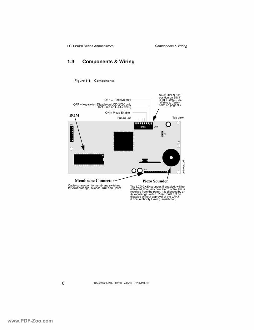
1.3 Components & Wiring
Figure 1-1: Components
Future use
ON = Piezo Enable
OFF = Key-switch Disable on LCD-2X20 only(not used on LCD-2X20L)
OFF = Receive only
Top view
Note: OPEN (Up) position on SW1 is OFF state (See “Wiring to Termi-nals” on page 9.).
ROM
The LCD-2X20 sounder, if enabled, will be activated when any new alarm or trouble is received from the panel. It is silenced by an Acknowledge switch. Piezo must not be disabled without approval of the LAHJ (Local Authority Having Jurisdiction).
Piezo SounderMembrane ConnectorCable connection to membrane switches for Acknowledge, Silence, Drill and Reset.
Lcd4
0brd
.cdr
www.PDF-Zoo.com
LCD-2X20 Series Annunciators Components & Wiring
9Document 51105 Rev B 7/25/00 P/N 51105:B
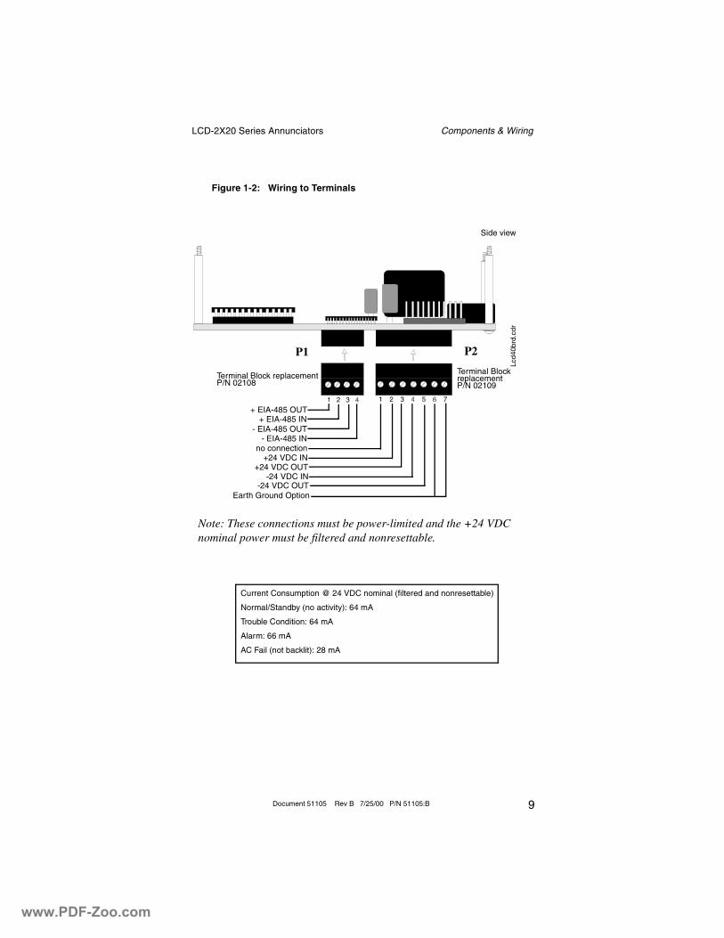
Figure 1-2: Wiring to Terminals
Terminal Block replacement P/N 02108
P1 P2
Terminal Block replacement P/N 02109
+ EIA-485 OUT+ EIA-485 IN
- EIA-485 OUT- EIA-485 IN
no connection+24 VDC IN
+24 VDC OUT-24 VDC IN
-24 VDC OUTEarth Ground Option
Note: These connections must be power-limited and the +24 VDC nominal power must be filtered and nonresettable.
Current Consumption @ 24 VDC nominal (filtered and nonresettable)
Normal/Standby (no activity): 64 mA
Trouble Condition: 64 mA
Alarm: 66 mA
AC Fail (not backlit): 28 mA
Side view
Lcd4
0brd
.cdr
www.PDF-Zoo.com
LCD-2X20 Series Annunciators SW1 DIP Switch Settings
10 Document 51105 Rev B 7/25/00 P/N 51105:B
1.4 SW1 DIP Switch Settings
The Up position on DIP switch SW1 is the Off state. Refer to “DIP Switch Settings Example” on page 11, for an explanation of DIP switch positions. SW1 switch settings follow:
1 - On (Down) = Receive/Transmit, Off (up) = Receive Only.
Set switch 1 to Off (Up) position for all LCD-2X20 Series Annunci-ators except the last (or only) annunciator on the EIA-485 loop. Set switch to On (Down) position for the last or only annunciator on the EIA-485 loop to allow transmission of a supervision signal (and function switch depressions on the LCD-2X20) back to the FACP. The last or only annunciator must be set for Receive/Transmit (switch 1 in the Down position).
A break (open circuit) in the power or EIA-485 connections creates an LCD-2X20 Series Annunciator fault at the AFP-100 panel. All annunciators before the break will continue to display information (but the function switches on the LCD-2X20 will no longer operate).
2 - LCD-2X20 Only (not used on the LCD-2X20L) On (Down) = Key-switch enabled, Off (Up) = Key-switch disabled.
Switch 2 set to the On (Down) position enables key-switch opera-tion. The key-switch may now be used to enable the LCD-2X20 membrane switches, allowing remote switch functions, or lockout the switches, preventing remote switch functions
Switch 2 set to the Off (Up) position disables the key-switch opera-tion. Refer to “Switch Functions for LCD-2X20 Only” on page 14, for key-switch function description.
3 - On (Down) = Piezo sounder enabled, Off (Up) = Piezo sounder disabled.
CAUTION: Piezo sounder must not be disabled without prior approval of the Local Authority Having Jurisdiction (LAHJ).
4 through 8 = Future use.
www.PDF-Zoo.com
LCD-2X20 Series Annunciators SW1 DIP Switch Settings
11Document 51105 Rev B 7/25/00 P/N 51105:B
.
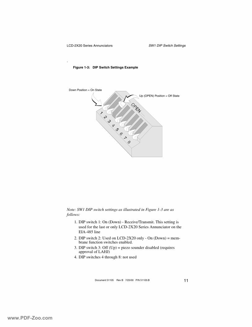
Note: SW1 DIP switch settings as illustrated in Figure 1-3 are asfollows:
1. DIP switch 1: On (Down) - Receive/Transmit. This setting is used for the last or only LCD-2X20 Series Annunciator on the EIA-485 line
2. DIP switch 2: Used on LCD-2X20 only - On (Down) = mem-brane function switches enabled.
3. DIP switch 3: Off (Up) = piezo sounder disabled (requires approval of LAHJ)
4. DIP switches 4 through 8: not used
Figure 1-3: DIP Switch Settings Example
Down Position = On State
Up (OPEN) Position = Off State
www.PDF-Zoo.com
LCD-2X20 Series Annunciators Typical Configuration
12 Document 51105 Rev B 7/25/00 P/N 51105:B
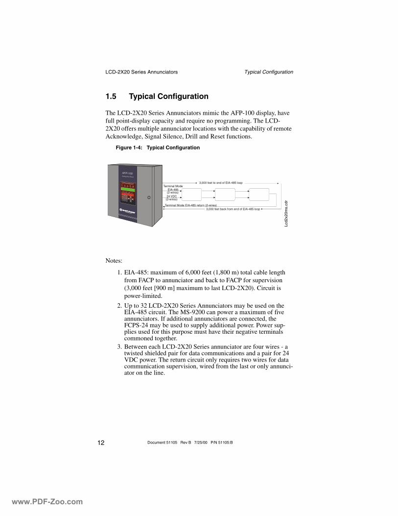
1.5 Typical Configuration
The LCD-2X20 Series Annunciators mimic the AFP-100 display, have full point-display capacity and require no programming. The LCD-2X20 offers multiple annunciator locations with the capability of remote Acknowledge, Signal Silence, Drill and Reset functions.
Notes:
1. EIA-485: maximum of 6,000 feet (1,800 m) total cable length from FACP to annunciator and back to FACP for supervision (3,000 feet [900 m] maximum to last LCD-2X20). Circuit is power-limited.
2. Up to 32 LCD-2X20 Series Annunciators may be used on the EIA-485 circuit. The MS-9200 can power a maximum of five annunciators. If additional annunciators are connected, the FCPS-24 may be used to supply additional power. Power sup-plies used for this purpose must have their negative terminals commoned together.
3. Between each LCD-2X20 Series annunciator are four wires - a twisted shielded pair for data communications and a pair for 24 VDC power. The return circuit only requires two wires for data communication supervision, wired from the last or only annunci-ator on the line.
Terminal ModeEIA-485
Terminal Mode EIA-485 return (2-wires)
3,000 feet to end of EIA-485 loop
3,000 feet back from end of EIA-485 loop
(2-wires)
(2-wires)24 VDC
Figure 1-4: Typical Configuration
Lcd2
x20m
s.cd
r
www.PDF-Zoo.com
Operation Display Patterns
13Document 51105 Rev B 7/25/00 P/N 51105:B
Section 2: Operation
2.1 Display Patterns
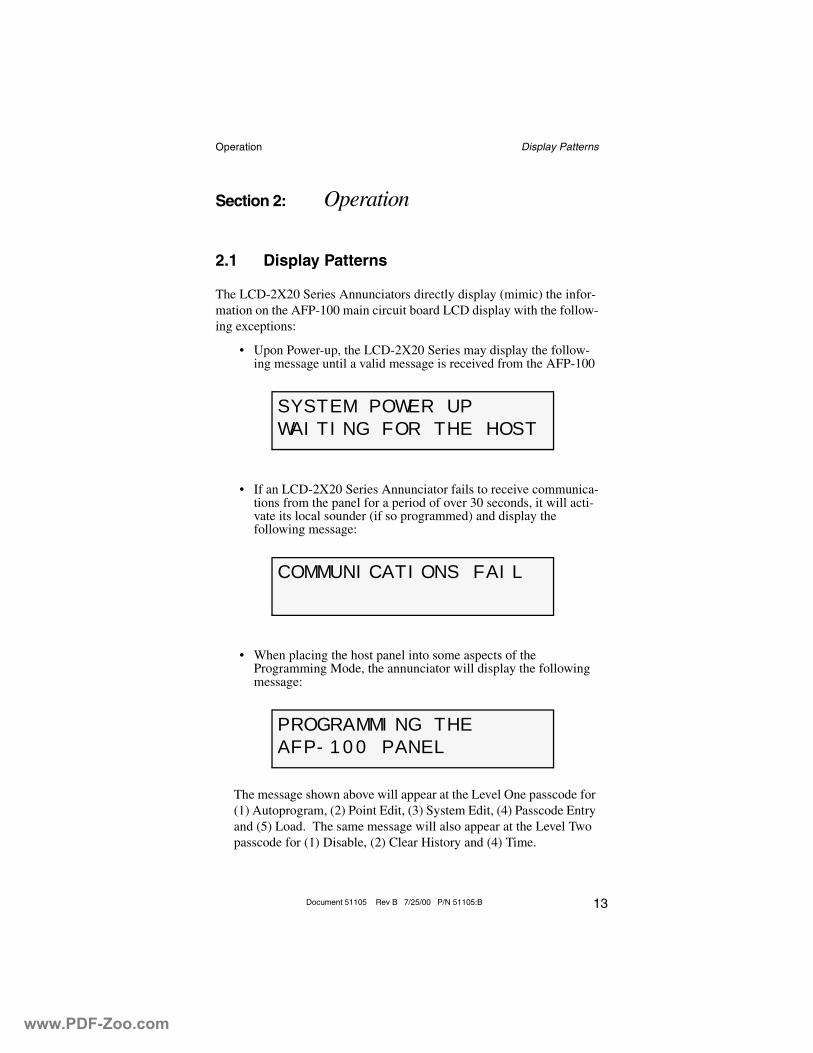
The LCD-2X20 Series Annunciators directly display (mimic) the infor-mation on the AFP-100 main circuit board LCD display with the follow-ing exceptions:
• Upon Power-up, the LCD-2X20 Series may display the follow-ing message until a valid message is received from the AFP-100
• If an LCD-2X20 Series Annunciator fails to receive communica-tions from the panel for a period of over 30 seconds, it will acti-vate its local sounder (if so programmed) and display the following message:
• When placing the host panel into some aspects of the Programming Mode, the annunciator will display the following message:
The message shown above will appear at the Level One passcode for (1) Autoprogram, (2) Point Edit, (3) System Edit, (4) Passcode Entry and (5) Load. The same message will also appear at the Level Two passcode for (1) Disable, (2) Clear History and (4) Time.
SYSTEM POWER UP
WAITING FOR THE HOST
COMMUNICATIONS FAIL
PROGRAMMING THE
AFP-100 PANEL
www.PDF-Zoo.com
Operation Switch Functions for LCD-2X20 Only
14 Document 51105 Rev B 7/25/00 P/N 51105:B
2.2 Switch Functions for LCD-2X20 Only
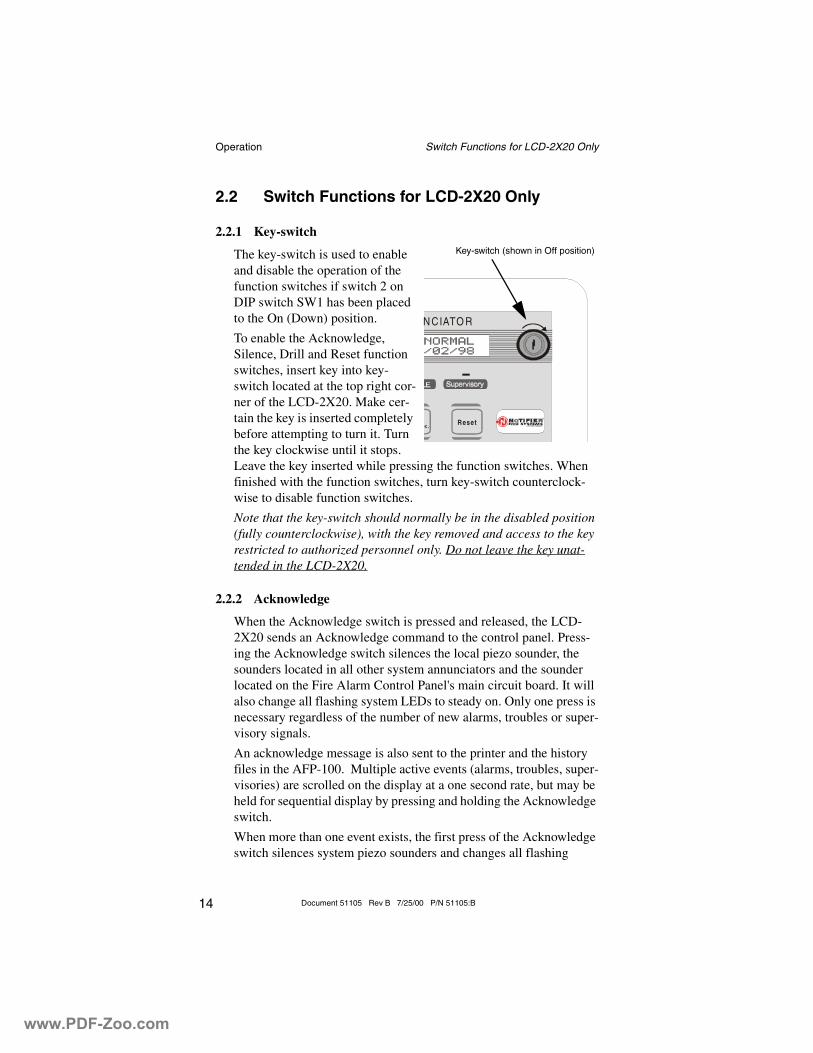
2.2.1 Key-switch
The key-switch is used to enable and disable the operation of the function switches if switch 2 on DIP switch SW1 has been placed to the On (Down) position.
To enable the Acknowledge, Silence, Drill and Reset function switches, insert key into key-switch located at the top right cor-ner of the LCD-2X20. Make cer-tain the key is inserted completely before attempting to turn it. Turn the key clockwise until it stops. Leave the key inserted while pressing the function switches. When finished with the function switches, turn key-switch counterclock-wise to disable function switches.
Note that the key-switch should normally be in the disabled position (fully counterclockwise), with the key removed and access to the key restricted to authorized personnel only. Do not leave the key unat-tended in the LCD-2X20.
2.2.2 Acknowledge
When the Acknowledge switch is pressed and released, the LCD-2X20 sends an Acknowledge command to the control panel. Press-ing the Acknowledge switch silences the local piezo sounder, the sounders located in all other system annunciators and the sounder located on the Fire Alarm Control Panel's main circuit board. It will also change all flashing system LEDs to steady on. Only one press is necessary regardless of the number of new alarms, troubles or super-visory signals.
An acknowledge message is also sent to the printer and the history files in the AFP-100. Multiple active events (alarms, troubles, super-visories) are scrolled on the display at a one second rate, but may be held for sequential display by pressing and holding the Acknowledge switch.
When more than one event exists, the first press of the Acknowledge switch silences system piezo sounders and changes all flashing
Resetec.
N CIATO R
Key-switch (shown in Off position)
www.PDF-Zoo.com
Operation Switch Functions for LCD-2X20 Only
15Document 51105 Rev B 7/25/00 P/N 51105:B
LEDs to steady on. The second press of the switch stops the scroll-ing and holds the event on the display for one minute. Subsequent pressing of the switch 'steps' through each active event.
2.2.3 Silence
When the Silence switch is pressed and released, the LCD-2X20 sends a signal silence command to the control panel. The Silence switch performs the same functions as the Acknowledge switch. In addition, if an alarm exists, it turns off all silenceable NACs and causes the FACP Alarm Silence LED to turn on while the LCD-2X20 will display a 'silenced' message. It also sends an 'Alarm Silenced' message to the printer and the history file within the AFP-100. A subsequent new alarm will resound the appropriate NACs (Notification Appliance Circuits) and local sounders.
2.2.4 Drill: Hold 2 Sec.
When the Drill switch is pressed and held for at least two seconds (time required to prevent accidental activations), the LCD-2X20 will transmit a drill command to the control panel. This command causes the FACP to turn on both main panel NAC outputs and all silence-able circuits (all control modules/NACs that are programmed silenceable). In the event that the system was previously silenced, the drill command will also turn off the Alarm Silence LED. The 'Man-ual Evacuate' message is shown on the LCD-2X20 display. The same message is sent to the FACP display, printer and history files. The Silence switch operates on silenceable NAC outputs only.
2.2.5 Reset
When the System Reset switch is pressed and released, the LCD-2X20 sends a Reset command to the control panel. This will turn off all CMX modules and Notification Appliance Circuits, temporarily turns off resettable power to 4-wire detectors, causes a 'System All Normal' message to be displayed on the LCD-2X20 and sends a 'System Reset' message to the FACP display, printer and AFP-100 history files. It also turns on all system LEDs, piezo sounders and LCD display segments as long as the Reset switch is held (lamp test). Any alarm or trouble that exists after a Reset will resound the system.
www.PDF-Zoo.com
Operation LED Indicators (all LCD-2X20 Series)
16 Document 51105 Rev B 7/25/00 P/N 51105:B
2.3 LED Indicators (all LCD-2X20 Series)
2.3.1 Power
This is a green LED which illuminates if AC power is applied to the host FACP. The green LED will turn off if AC power to the host FACP is lost.
2.3.2 Fire Alarm
This is a red LED that flashes when one or more fire alarms occur. It illuminates steadily when an Acknowledge or Silence switch is pressed. The Alarm LED turns off when the Reset switch is pressed.
2.3.3 Supervisory
This is a yellow LED that flashes when one or more supervisory conditions occur, such as a sprinkler valve tamper condition. It illu-minates steadily when an Acknowledge or Silence switch is pressed. It turns off when the Reset switch is pressed.
2.3.4 Trouble
This is a yellow LED that flashes when one or more trouble condi-tions occur. It stays on steady when an Acknowledge or Silence switch is pressed. The LED turns off when all trouble conditions are cleared. This LED will also illuminate if the microprocessor watch-dog circuit within the LCD-2X20 Series is activated.
www.PDF-Zoo.com
Mounting Annunciator Preparation
17Document 51105 Rev B 7/25/00 P/N 51105:B
Section 3: Mounting
3.1 Annunciator Preparation
The LCD-2X20 Series Annunciators can be surface mounted in a three-gang electrical box such as the P/N SBB-3 (2.75" depth) or semi-flush mounted in a three-gang electrical box, P/N 10103 or equivalent, with a minimum depth of 2 3/16". The LCD-2X20 Series Annunciators cannot be mounted in three gangable electrical switch boxes connected together. Select and remove the appropriate knockout(s), pull the neces-sary wires through the knockouts and mount the three-gang box in or on the wall depending on the type of installation desired. Be certain that power is not applied to the wiring during the installation procedure.
Note: To ensure static protection, all enclosures, including the LCD-2X20 Series electrical box, must be connected to earth ground! Never use the shield for grounding purposes.
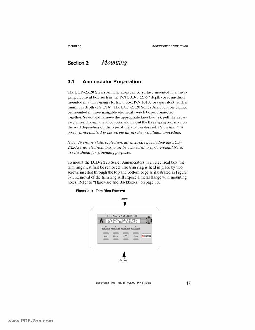
To mount the LCD-2X20 Series Annunciators in an electrical box, the trim ring must first be removed. The trim ring is held in place by two screws inserted through the top and bottom edge as illustrated in Figure 3-1. Removal of the trim ring will expose a metal flange with mounting holes. Refer to “Hardware and Backboxes” on page 18.
A ck S ilen ce R es e tD rillH o ld 2 sec.
FIR E ALA R M A N N U N C IATO R
Figure 3-1: Trim Ring Removal
Screw
Screw
www.PDF-Zoo.com
Mounting Annunciator Preparation
18 Document 51105 Rev B 7/25/00 P/N 51105:B
Ack Silence ResetDrillHold 2 sec.
FIR E A LA R M A N N U NC IATO R
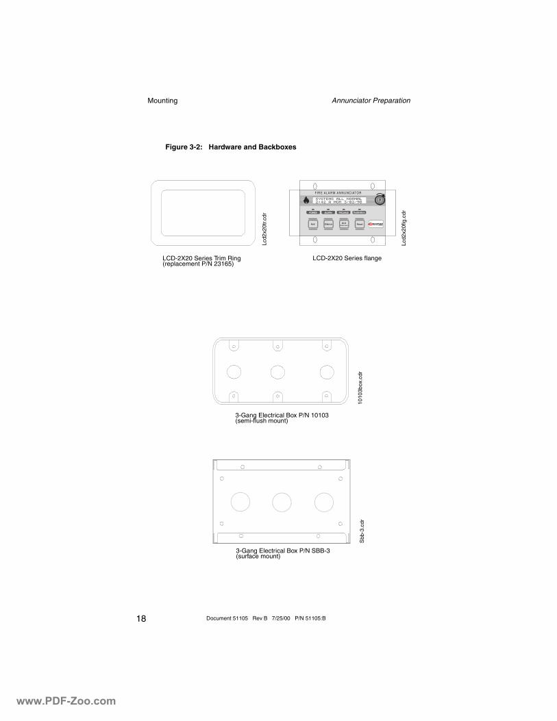
Figure 3-2: Hardware and Backboxes
LCD-2X20 Series flangeLCD-2X20 Series Trim Ring(replacement P/N 23165)
3-Gang Electrical Box P/N 10103(semi-flush mount)
3-Gang Electrical Box P/N SBB-3(surface mount)
Lcd2
x20f
lg.c
dr
Lcd2
x20t
r.cdr
1010
3box
.cdr
Sbb
-3.c
dr
www.PDF-Zoo.com
Mounting Semi-flush Mount Backbox
19Document 51105 Rev B 7/25/00 P/N 51105:B
3.2 Semi-flush Mount Backbox
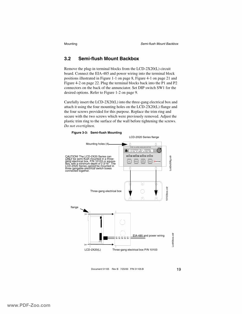
Remove the plug-in terminal blocks from the LCD-2X20(L) circuit board. Connect the EIA-485 and power wiring into the terminal block positions illustrated in Figure 1-1 on page 8, Figure 4-1 on page 21 and Figure 4-2 on page 22. Plug the terminal blocks back into the P1 and P2 connectors on the back of the annunciator. Set DIP switch SW1 for the desired options. Refer to Figure 1-2 on page 9.
Carefully insert the LCD-2X20(L) into the three-gang electrical box and attach it using the four mounting holes on the LCD-2X20(L) flange and the four screws provided for this purpose. Replace the trim ring and secure with the two screws which were previously removed. Adjust the plastic trim ring to the surface of the wall before tightening the screws. Do not overtighten.
Ack Silence ResetDri llHold 2 sec.
FIR E A LA R M A N N U N C IATO R
Figure 3-3: Semi-flush MountingLCD-2X20 Series flange
Mounting holes (4)
Three-gang electrical box
CAUTION! The LCD-2X20 Series can ONLY be semi-flush mounted in a three-gang electrical box, P/N 10103 or equiva-lent, with a minimum depth of 2 3/16". The LCD-2X20 Series cannot be mounted in three gangable electrical switch boxes connected together.
LCD-2X20(L) Three-gang electrical box P/N 10103
flange
EIA-485 and power wiring
Lcd2
x20f
lg.c
dr
1010
3box
.cdr
Lcd4
0box
.cdr
www.PDF-Zoo.com
Mounting Surface Mount Backbox
20 Document 51105 Rev B 7/25/00 P/N 51105:B
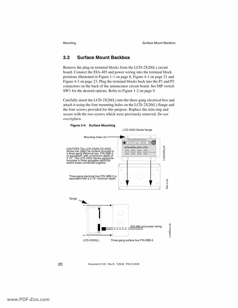
3.3 Surface Mount Backbox
Remove the plug-in terminal blocks from the LCD-2X20(L) circuit board. Connect the EIA-485 and power wiring into the terminal block positions illustrated in Figure 1-1 on page 8, Figure 4-1 on page 21 and Figure 4-3 on page 23. Plug the terminal blocks back into the P1 and P2 connectors on the back of the annunciator circuit board. Set DIP switch SW1 for the desired options. Refer to Figure 1-2 on page 9.
Carefully insert the LCD-2X20(L) into the three-gang electrical box and attach it using the four mounting holes on the LCD-2X20(L) flange and the four screws provided for this purpose. Replace the trim ring and secure with the two screws which were previously removed. Do not overtighten.
Ack Silence ResetDrillHo ld 2 s ec .
F IR E A LA R M AN N U N C IATOR
Figure 3-4: Surface MountingLCD-2X20 Series flange
Mounting holes (4)
Three-gang electrical box P/N SBB-3 or equivalent with a 2.75" minimum depth.
CAUTION! The LCD-2X20LCD-2X20 Series can ONLY be surface mounted in a three-gang electrical box, P/N SBB-3 or equivalent, with a minimum depth of 2.75". The LCD-2X20 Series cannot be mounted in three gangable electrical switch boxes connected together.
LCD-2X20(L) Three-gang surface box P/N SBB-3
flange
EIA-485 and power wiring
Lcd2
x20f
lg.c
drS
bb-3
.cdr
Lcd4
0box
.cdr
www.PDF-Zoo.com
Electrical Connections Power Connections
21Document 51105 Rev B 7/25/00 P/N 51105:B
Section 4: Electrical Connections
4.1 Power Connections
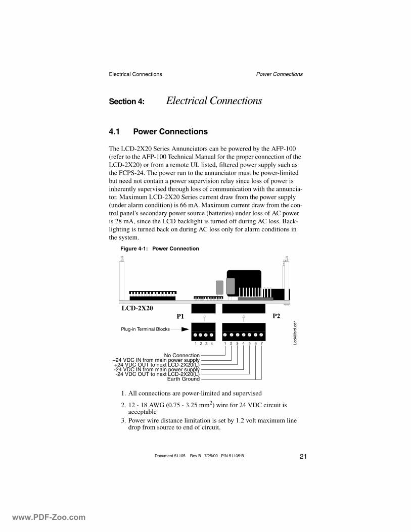
The LCD-2X20 Series Annunciators can be powered by the AFP-100 (refer to the AFP-100 Technical Manual for the proper connection of the LCD-2X20) or from a remote UL listed, filtered power supply such as the FCPS-24. The power run to the annunciator must be power-limited but need not contain a power supervision relay since loss of power is inherently supervised through loss of communication with the annuncia-tor. Maximum LCD-2X20 Series current draw from the power supply (under alarm condition) is 66 mA. Maximum current draw from the con-trol panel's secondary power source (batteries) under loss of AC power is 28 mA, since the LCD backlight is turned off during AC loss. Back-lighting is turned back on during AC loss only for alarm conditions in the system.
1. All connections are power-limited and supervised
2. 12 - 18 AWG (0.75 - 3.25 mm2) wire for 24 VDC circuit is acceptable
3. Power wire distance limitation is set by 1.2 volt maximum line drop from source to end of circuit.
Figure 4-1: Power Connection
P1 P2LCD-2X20
Plug-in Terminal Blocks
Lcd4
0brd
.cdr
No Connection+24 VDC IN from main power supply+24 VDC OUT to next LCD-2X20(L)-24 VDC IN from main power supply-24 VDC OUT to next LCD-2X20(L)
Earth Ground
www.PDF-Zoo.com
Electrical Connections EIA-485 Connections
22 Document 51105 Rev B 7/25/00 P/N 51105:B
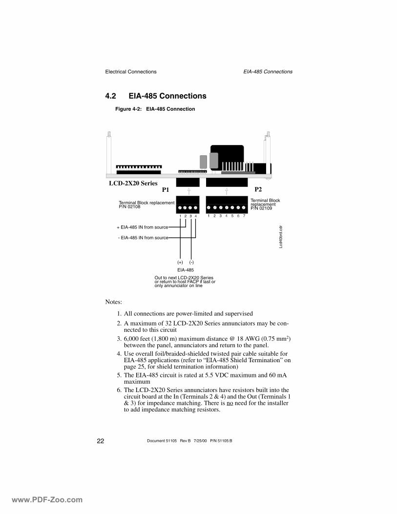
4.2 EIA-485 Connections
Notes:
1. All connections are power-limited and supervised
2. A maximum of 32 LCD-2X20 Series annunciators may be con-nected to this circuit
3. 6,000 feet (1,800 m) maximum distance @ 18 AWG (0.75 mm2) between the panel, annunciators and return to the panel.
4. Use overall foil/braided-shielded twisted pair cable suitable for EIA-485 applications (refer to “EIA-485 Shield Termination” on page 25, for shield termination information)
5. The EIA-485 circuit is rated at 5.5 VDC maximum and 60 mA maximum
6. The LCD-2X20 Series annunciators have resistors built into the circuit board at the In (Terminals 2 & 4) and the Out (Terminals 1 & 3) for impedance matching. There is no need for the installer to add impedance matching resistors.
Figure 4-2: EIA-485 Connection
Terminal Block replacement P/N 02108
P1 P2
Terminal Block replacement P/N 02109
(+) (-)
EIA-485
Out to next LCD-2X20 Series or return to host FACP if last or only annunciator on line
+ EIA-485 IN from source
- EIA-485 IN from source
LCD-2X20 Series
Lcd4
0brd
.cdr
www.PDF-Zoo.com
Electrical Connections DIM-485 Connections
23Document 51105 Rev B 7/25/00 P/N 51105:B
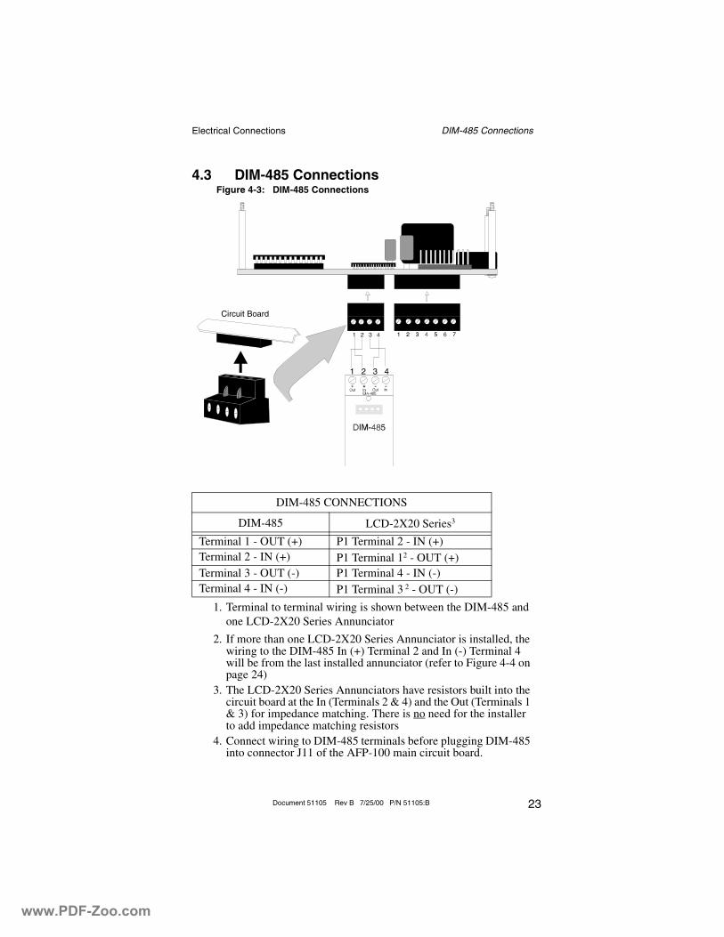
4.3 DIM-485 Connections
1. Terminal to terminal wiring is shown between the DIM-485 and one LCD-2X20 Series Annunciator
2. If more than one LCD-2X20 Series Annunciator is installed, the wiring to the DIM-485 In (+) Terminal 2 and In (-) Terminal 4 will be from the last installed annunciator (refer to Figure 4-4 on page 24)
3. The LCD-2X20 Series Annunciators have resistors built into the circuit board at the In (Terminals 2 & 4) and the Out (Terminals 1 & 3) for impedance matching. There is no need for the installer to add impedance matching resistors
4. Connect wiring to DIM-485 terminals before plugging DIM-485 into connector J11 of the AFP-100 main circuit board.
DIM-485 CONNECTIONS
DIM-485 LCD-2X20 Series3
Terminal 1 - OUT (+) P1 Terminal 2 - IN (+)Terminal 2 - IN (+) P1 Terminal 12 - OUT (+)Terminal 3 - OUT (-) P1 Terminal 4 - IN (-)Terminal 4 - IN (-) P1 Terminal 3 2 - OUT (-)
Figure 4-3: DIM-485 Connections
Circuit Board
1 2 3 4
www.PDF-Zoo.com
Electrical Connections Dim-485 Installation
24 Document 51105 Rev B 7/25/00 P/N 51105:B
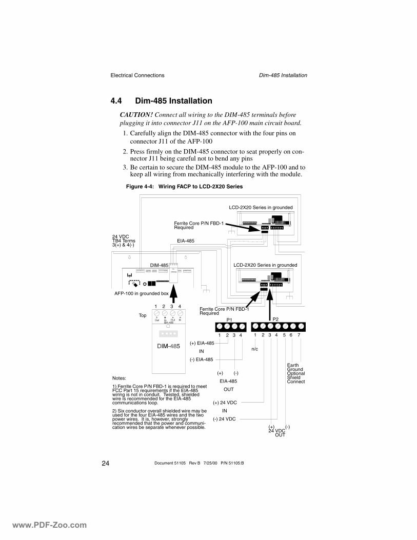
4.4 Dim-485 Installation
CAUTION! Connect all wiring to the DIM-485 terminals before plugging it into connector J11 on the AFP-100 main circuit board.
1. Carefully align the DIM-485 connector with the four pins on connector J11 of the AFP-100
2. Press firmly on the DIM-485 connector to seat properly on con-nector J11 being careful not to bend any pins
3. Be certain to secure the DIM-485 module to the AFP-100 and to keep all wiring from mechanically interfering with the module.
Figure 4-4: Wiring FACP to LCD-2X20 Series
1 2 3 4
P1 P2
1 2 3 4 1 2 3 4 5 6 7
Ferrite Core P/N FBD-1 Required
Ferrite Core P/N FBD-1 Required
LCD-2X20 Series in grounded
LCD-2X20 Series in grounded
EIA-48524 VDC TB4 Terms 3(+) & 4(-)
DIM-485
AFP-100 in grounded box
Top
(+) EIA-485
IN
(-) EIA-485
(+) (-)
EIA-485
OUT
(+) 24 VDC
IN
(-) 24 VDC
n/c
Earth Ground Optional Shield Connect
(+) (-)24 VDC OUT
Notes:
1) Ferrite Core P/N FBD-1 is required to meet FCC Part 15 requirements if the EIA-485 wiring is not in conduit. Twisted, shielded wire is recommended for the EIA-485 communications loop.
2) Six conductor overall shielded wire may be used for the four EIA-485 wires and the two power wires. It is, however, strongly recommended that the power and communi-cation wires be separate whenever possible.
www.PDF-Zoo.com
EIA-485 Shield Termination Shield Not in Conduit
25Document 51105 Rev B 7/25/00 P/N 51105:B
Section 5: EIA-485 Shield Termination
The EIA-485 circuit must be wired using a twisted, shielded pair cable with a characteristic impedance of 120 ohms (+/- 20%). Do not run cable adjacent to or in the same conduit as 120 VAC service, noisy elec-trical circuits that are powering mechanical bells or horns, audio circuits above 25 VRMS, motor control circuits or SCR power circuits.
Note: To ensure static (ESD - electrostatic discharge) protection, all enclosures, including the LCD-2X20 Series electrical box, must be connected to earth ground! Never use the EIA-485 shield for this purpose. The EIA-485 shield is for radiated noise emission protection (RFI, EMI). Refer to the following figures for details on EIA-485 shield termination.
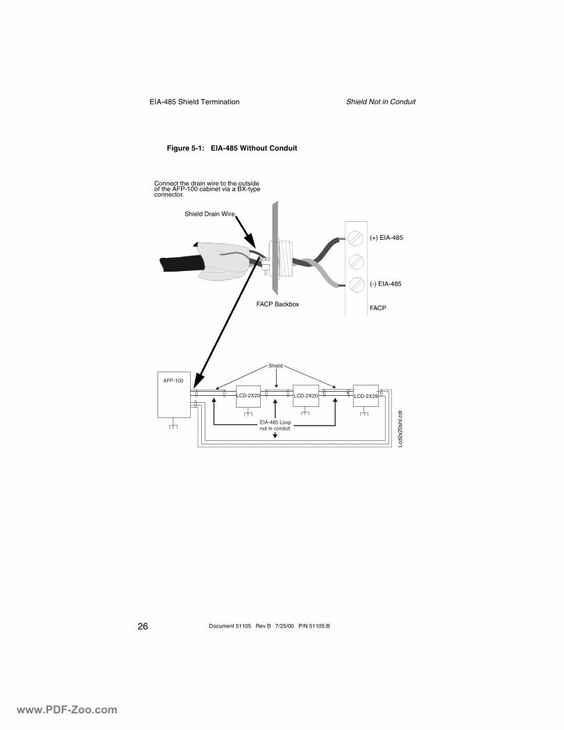
5.1 Shield Not in Conduit
The EIA-485 line allows the FACP to communicate with the LCD-2X20 Series Annunciators. The shield for the EIA-485 line must be connected to earth ground at the FACP but must be left floating (no connection) at the annunciator if it is the first or only device on the EIA-485 line. If a second annunciator is connected, the shield leaving the first annunciator must be left floating. The shield entering the second annunciator must be connected to the three-gang box or Earth Ground terminal (P2-7) on the second annunciator. If additional annunciators are connected, the shield leaving each enclosure must be left floating and the shield enter-ing each must be connected to the three-gang box or the Earth Ground terminal (P2-7) on the annunciator.
www.PDF-Zoo.com
EIA-485 Shield Termination Shield Not in Conduit
26 Document 51105 Rev B 7/25/00 P/N 51105:B
EIA-485 Loopnot in conduit
Shield
LCD-2X20 LCD-2X20 LCD-2X20
AFP-100
Figure 5-1: EIA-485 Without Conduit
Connect the drain wire to the outside of the AFP-100 cabinet via a BX-type connector.
Shield Drain Wire
FACP Backbox
(+) EIA-485
(-) EIA-485
FACP
Lcd2
x20s
hl.c
dr
www.PDF-Zoo.com
EIA-485 Shield Termination Shield in Full Conduit
27Document 51105 Rev B 7/25/00 P/N 51105:B
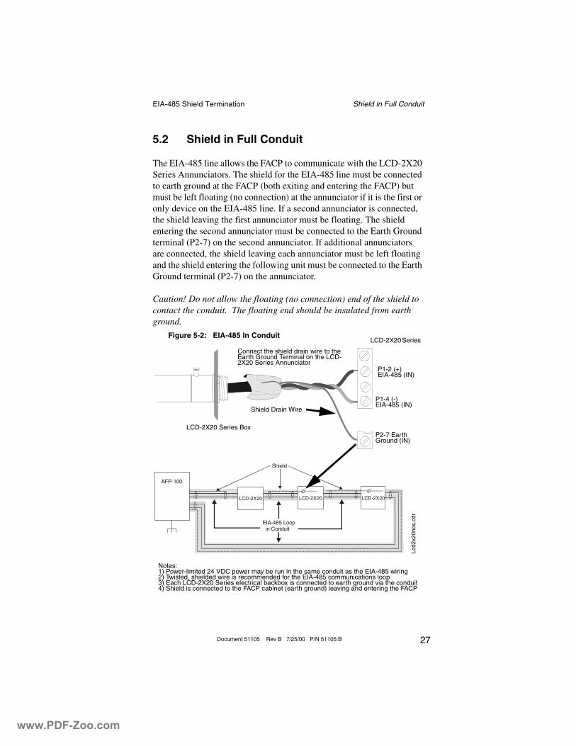
5.2 Shield in Full Conduit
The EIA-485 line allows the FACP to communicate with the LCD-2X20 Series Annunciators. The shield for the EIA-485 line must be connected to earth ground at the FACP (both exiting and entering the FACP) but must be left floating (no connection) at the annunciator if it is the first or only device on the EIA-485 line. If a second annunciator is connected, the shield leaving the first annunciator must be floating. The shield entering the second annunciator must be connected to the Earth Ground terminal (P2-7) on the second annunciator. If additional annunciators are connected, the shield leaving each annunciator must be left floating and the shield entering the following unit must be connected to the Earth Ground terminal (P2-7) on the annunciator.
Caution! Do not allow the floating (no connection) end of the shield to contact the conduit. The floating end should be insulated from earth ground.
EIA-485 Loop in Conduit
Shield
LCD-2X20 LCD-2X20 LCD-2X20
AFP-100
Ear th G round Ear th G round
Figure 5-2: EIA-485 In Conduit
LCD-2X20 Series Box
LCD-2X20 Series
P1-2 (+)EIA-485 (IN)
P1-4 (-)EIA-485 (IN)
P2-7 Earth Ground (IN)
Connect the shield drain wire to the Earth Ground Terminal on the LCD-2X20 Series Annunciator
Shield Drain Wire
Notes:1) Power-limited 24 VDC power may be run in the same conduit as the EIA-485 wiring2) Twisted, shielded wire is recommended for the EIA-485 communications loop3) Each LCD-2X20 Series electrical backbox is connected to earth ground via the conduit4) Shield is connected to the FACP cabinet (earth ground) leaving and entering the FACP
Lcd2
x20n
os.c
dr
www.PDF-Zoo.com
Programming Programming the AFP-100
28 Document 51105 Rev B 7/25/00 P/N 51105:B
Section 6: Programming
6.1 Programming the AFP-100
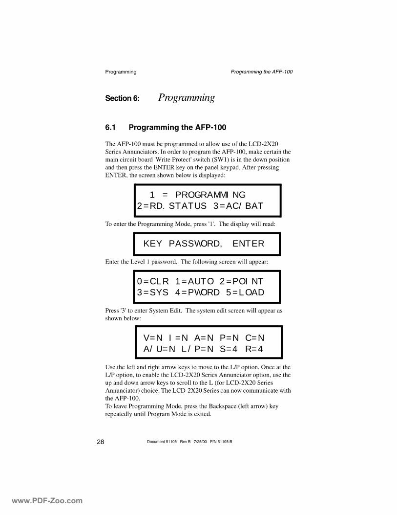
The AFP-100 must be programmed to allow use of the LCD-2X20 Series Annunciators. In order to program the AFP-100, make certain the main circuit board 'Write Protect' switch (SW1) is in the down position and then press the ENTER key on the panel keypad. After pressing ENTER, the screen shown below is displayed:
1 = PROGRAMMING
2=RD.STATUS 3=AC/BAT
To enter the Programming Mode, press '1'. The display will read:
KEY PASSWORD, ENTER
Enter the Level 1 password. The following screen will appear:
0=CLR 1=AUTO 2=POINT
3=SYS 4=PWORD 5=LOAD
Press '3' to enter System Edit. The system edit screen will appear as shown below:
V=N I=N A=N P=N C=N
A/U=N L/P=N S=4 R=4
Use the left and right arrow keys to move to the L/P option. Once at the L/P option, to enable the LCD-2X20 Series Annunciator option, use the up and down arrow keys to scroll to the L (for LCD-2X20 Series Annunciator) choice. The LCD-2X20 Series can now communicate with the AFP-100.To leave Programming Mode, press the Backspace (left arrow) key repeatedly until Program Mode is exited.
www.PDF-Zoo.com
29Document 51105 Rev B 7/25/00 P/N 51105:B
AAcknowledge switch 6, 7, 12, 14, 15AFP-100 6, 13
programming 28Alarm LED 6, 7, 16Alarm Silence LED 15annunciators
maximum per EIA-485 circuit 7, 12Bbackboxes 18backlight 7, 21Ccommunication 6
see also EIA-485 circuit 6communications fault 13configuration 12control switches 6current rating 21
AC fail 9alarm 9standby 9trouble 9
DDIM-485 23
connections 23wiring 23
Dim-485installation 24
DIM-485 module 7DIP Switch settings 8, 10, 11
function switches 11piezo sounder 11receive/transmit 10, 11SW1 10
DIP SwitchesSW1 19, 20
DIP switches 7display
scroll 14, 15step through 15
distance from panel 7, 12
www.PDF-Zoo.com
30 Document 51105 Rev B 7/25/00 P/N 51105:B
Drill switch 6, 7, 12, 14, 15Eearth ground 9, 17, 25, 27EIA-485 circuit 6, 7, 12, 19, 22, 25, 27EIA-485 circuit fault 10EIA-485 connection 22electrical box 18electrical connections 21electrostatic discharge 25Ffault
communication failure 10FCC Part 15 requirements 24Ferrite Core 24filtered 9flange 18, 20function switches 6, 7
enable/disable 11, 14Hhost panel
programming 13Iimpedance 22impedance matching 23KKey-switch
enable/disable 10key-switch 6, 14
enable/disable 7Llamp test 15LCD display 7, 13
mimic control panel display 6see also Liquid Crystal Display 6
LCD-2X20 7, 10, 14, 15see also LCD-2X20 Series Annunciators
LCD-2X20 Series Annunciator 12, 13, 16, 17, 19, 20, 21LCD-2X20 Series Annunciator display
custom alpha labels 6device type 6point alarm 6
www.PDF-Zoo.com
31Document 51105 Rev B 7/25/00 P/N 51105:B
supervisory 6system point status 6trouble 6zone 6
LCD-2X20 Series Annunciators 6LCD-2X20L 7Liquid Crystal Display 6Local Authority Having Jurisdiction 8, 10MManual Evacuate 15mounting 7, 17, 19
semi-flush 7surface 7, 20
NNAC
see also Notification Appliance Circuit 15nonresettable 9Ooperation 13Ppiezo sounder 7, 15
alarm resound 7enable/disable 8, 10, 11silence 14trouble resound 7
power connection 21Power LED 6, 7, 16power source 6, 9, 12, 21power-limited 9, 12, 21, 22power-up 13programming 7, 12
AFP-100 13, 28RReceive/Transmit 10, 11Reset switch 6, 12, 14, 15resettable power 15resistors
impedance matching 22, 23ROM 8SSBB-3 electrical box 17, 18, 20
www.PDF-Zoo.com
32 Document 51105 Rev B 7/25/00 P/N 51105:B
semi-flush mount 7semi-flush mounting 19shield 25, 27Signal Silence switch 7, 12silence
piezo sounder 14Silence switch 6, 14, 15static 25static protection 17supervised 21Supervisory LED 6, 7, 16surface mounting 7, 20SW1 DIP Switch 10switch functions 14System LEDs 15, 16system LEDs 14System Reset switch 7System Status LEDs 7system status LEDs 6Tterminal block 7, 9, 19, 20three-gang electrical box 17, 19, 20trim ring 17, 18, 19, 20Trouble LED 6, 7, 16Wwire
distance 21requirements 12size 21type 22, 25
wiring 12, 19, 23, 24, 25wiring connections 9
www.PDF-Zoo.com

33Document 51105 Rev B 7/25/00 P/N 51105:B
Notes
www.PDF-Zoo.com

34 Document 51105 Rev B 7/25/00 P/N 51105:B
Notes
www.PDF-Zoo.com

LimWarSm.p65 01/10/2000
The manufacturer warrants its products to be free from defects in materials andworkmanship for eighteen (18) months from the date of manufacture, under normaluse and service. Products are date-stamped at time of manufacture. The sole andexclusive obligation of the manufacturer is to repair or replace, at its option, free ofcharge for parts and labor, any part which is defective in materials or workmanshipunder normal use and service. For products not under the manufacturer's date-stamp control, the warranty is eighteen (18) months from date of original purchaseby the manufacturer's distributor unless the installation instructions or catalog setsforth a shorter period, in which case the shorter period shall apply. This warranty isvoid if the product is altered, repaired, or serviced by anyone other than themanufacturer or its authorized distributors, or if there is a failure to maintain theproducts and systems in which they operate in a proper and workable manner. Incase of defect, secure a Return Material Authorization form from our customerservice department. Return product, transportation prepaid, to the manufacturer.
This writing constitutes the only warranty made by this manufacturer with respectto its products. The manufacturer does not represent that its products will preventany loss by fire or otherwise, or that its products will in all cases provide theprotection for which they are installed or intended. Buyer acknowledges that themanufacturer is not an insurer and assumes no risk for loss or damages or the costof any inconvenience, transportation, damage, misuse, abuse, accident, or similarincident.
THE MANUFACTURER GIVES NO WARRANTY, EXPRESSED OR IMPLIED,OF MERCHANTABILITY, FITNESS FOR ANY PARTICULAR PURPOSE, OROTHERWISE WHICH EXTEND BEYOND THE DESCRIPTION ON THE FACEHEREOF. UNDER NO CIRCUMSTANCES SHALL THE MANUFACTURERBE LIABLE FOR ANY LOSS OF OR DAMAGE TO PROPERTY, DIRECT,INCIDENTAL, OR CONSEQUENTIAL, ARISING OUT OF THE USE OF, ORINABILITY TO USE THE MANUFACTURER'S PRODUCTS.FURTHERMORE, THE MANUFACTURER SHALL NOT BE LIABLE FOR ANYPERSONAL INJURY OR DEATH WHICH MAY ARISE IN THE COURSE OF,OR AS A RESULT OF, PERSONAL, COMMERCIAL, OR INDUSTRIAL USEOF ITS PRODUCTS.
This warranty replaces all previous warranties and is the only warranty made by themanufacturer. No increase or alteration, written or verbal, of the obligation of thiswarranty is authorized.
Limited Warranty
www.PDF-Zoo.com

World HeadquartersOne Fire-Lite Place, Northford, CT 06472-1653 USA
203-484-7161 • Fax 203-484-7118www.notifier.com
www.PDF-Zoo.com