Remote display technology enhances the cloud s user · PDF filemovies, games, slide...
13
Overview Cloud computing enables access to content – often robust, rich multimedia content like movies, games, slide presentations and mu- sic, but also straightforward data such as business reports or files – where it’s wanted and when it’s wanted. Obtaining this content from the cloud is not difficult, but viewing it personally or sharing it with others may be difficult primarily due to the size of the screen on the device that accessed this content. Crowding a group of five or six friends around a tablet or smartphone to watch a movie streaming from the cloud is not an engaging user experience. Sharing a slide presentation on a tablet PC with a group of business people in a conference room is not effective communication. All too frequently, the device where content from the cloud ends up is not the most ap- propriate type of device for viewing, sharing and experiencing it. Many of the devices that frequently obtain content from the cloud are mobile devices, such as tablet PCs, smart- phones, very thin laptops and others. These devices place a premium on mobility and, as a result, they may have small displays and few if any hardwired connectors that could link to another type of device where users could experience the content to its fullest. Remote display technology enhances the cloud’s user experience An effective way around this dilemma is a new technology known as remote mirroring and media display (RMD) technology or remote display technology. Texas Instruments Incorporated (TI) has drawn on its vast experience in multimedia processing, dis- play technologies, wireless connectivity and others to develop video proces- sors that offer a unique blend of capabilities and are supported by reference de- signs targeted at remote display applications covering a wide range of use cases. Different clouds, different needs Illustrations of cloud computing always feature a fluffy yet amorphous entity in the center labeled “The Cloud.” This is somewhat misleading, because cloud computing is actually made up of several different layers of clouds. In fact, most people interact with at least three different cloud layers over the course of a normal day (Figure 1). Raj Pawate, Distinguished Member, Technical Staff Gaurav Agarwal, Manager, Wi-Fi Display End Equipment Texas Instruments WHITE PAPER Home cloud Work cloud Infotainment cloud Figure 1. The three clouds: Three screens, anytime, anywhere
-
Upload
nguyentram -
Category
Documents
-
view
216 -
download
0
Transcript of Remote display technology enhances the cloud s user · PDF filemovies, games, slide...
Overview
Cloud computing enables access to content –
often robust, rich multimedia content like
movies, games, slide presentations and mu-
sic, but also straightforward data such as
business reports or files – where it’s wanted
and when it’s wanted. Obtaining this content
from the cloud is not difficult, but viewing it
personally or sharing it with others may be
difficult primarily due to the size of the screen
on the device that accessed this content.
Crowding a group of five or six friends
around a tablet or smartphone to watch a
movie streaming from the cloud is not an
engaging user experience. Sharing a slide
presentation on a tablet PC with a group of
business people in a conference room is not
effective communication.
All too frequently, the device where content
from the cloud ends up is not the most ap-
propriate type of device for viewing, sharing
and experiencing it. Many of the devices that
frequently obtain content from the cloud are
mobile devices, such as tablet PCs, smart-
phones, very thin laptops and others. These
devices place a premium on mobility and, as
a result, they may have small displays and
few if any hardwired connectors that could
link to another type of device where users
could experience the content to its fullest.
Remote display technology enhances the cloud’s user experience
An effective way around this dilemma is a new technology known as remote mirroring
and media display (RMD) technology or remote display technology. Texas Instruments
Incorporated (TI) has drawn on its vast experience in multimedia processing, dis-
play technologies, wireless connectivity and others to develop video proces-
sors that offer a unique blend of capabilities and are supported by reference de-
signs targeted at remote display applications covering a wide range of use cases.
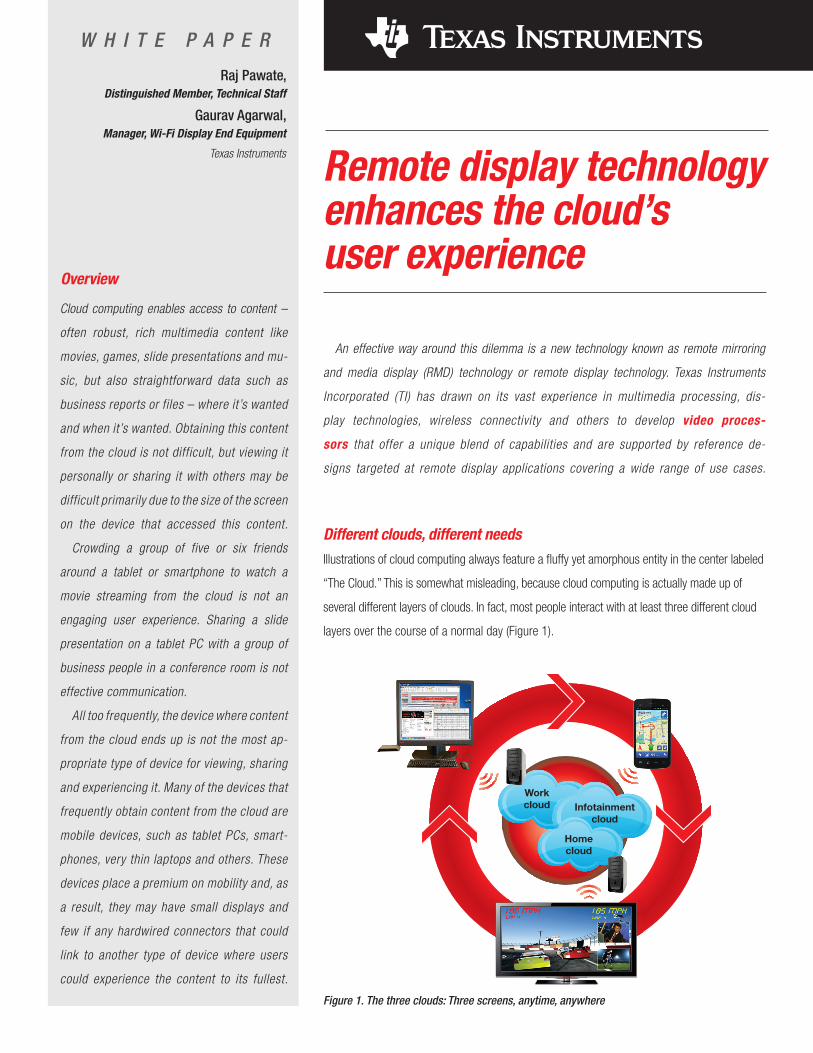
Different clouds, different needsIllustrations of cloud computing always feature a fluffy yet amorphous entity in the center labeled
“The Cloud.” This is somewhat misleading, because cloud computing is actually made up of
several different layers of clouds. In fact, most people interact with at least three different cloud
layers over the course of a normal day (Figure 1).
Raj Pawate,Distinguished Member, Technical Staff
Gaurav Agarwal,Manager, Wi-Fi Display End Equipment
Texas Instruments
W H I T E P A P E R
Home
cloud
Work
cloud Infotainment
cloud
Figure 1. The three clouds: Three screens, anytime, anywhere
Remote display technology enhances the cloud’s user experience August 2012
2 Texas Instruments
The cloud underlying all other layers is called the “infotainment cloud.” This is typically what is thought of
as the Internet. Public websites that can be accessed by anyone like YouTube, Facebook, Netflix, various news
outlets and many others comprise this layer. Much of the content in the infotainment cloud is either free or it can
be accessed for a small fee.
The next layer of cloud computing can be described as the “work cloud.” This is a private, limited-access
cloud that is typically found in a place of employment, although the work cloud for global enterprise can span
most of the continents. The people served by a work cloud are usually limited to the employees of a company or
members of an organization. Much of the information on work clouds is sensitive or confidential. Access is re-
stricted and the organization or company will employ extensive security measures to protect the content against
hacking, tampering and theft.
The third layer of cloud computing, the “home cloud,” is where content for a family, a small group of people
or even one person is stored and subsequently accessed, shared and experienced. A wide variety of end user
devices can be connected to the home cloud, including desktop personal computers, smartphones, tablet PCs,
TVs and audio/video entertainment systems. Like work clouds, but probably not as stringent, home clouds will
usually have some type of security for protecting the content and devices from intruders, viruses and all sorts of
malware.
An important aspect of cloud computing in general is the user’s ability to easily access each individual cloud
layer and seamlessly move back and forth from one to the others. The flexibility and agility inherent in remote
display technology allows it to serve all of the many use cases that are encountered on all layers of cloud
computing.
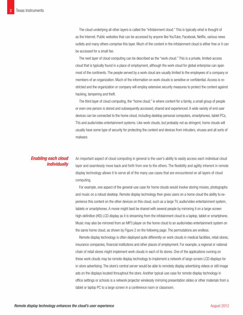
For example, one aspect of the general-use case for home clouds would involve storing movies, photographs
and music on a robust desktop. Remote display technology then gives users on a home cloud the ability to ex-
perience this content on the other devices on this cloud, such as a large TV, audio/video entertainment system,
tablets or smartphones. A movie might best be shared with several people by mirroring it on a large-screen
high-definition (HD) LCD display as it is streaming from the infotainment cloud to a laptop, tablet or smartphone.
Music may also be mirrored from an MP3 player on the home cloud to an audio/video entertainment system on
the same home cloud, as shown by Figure 2 on the following page. The permutations are endless.
Remote display technology is often deployed quite differently on work clouds in medical facilities, retail stores,
insurance companies, financial institutions and other places of employment. For example, a regional or national
chain of retail stores might implement work clouds in each of its stores. One of the applications running on
these work clouds may be remote display technology to implement a network of large-screen LCD displays for
in-store advertising. The store’s central server would be able to remotely display advertising videos or still image
ads on the displays located throughout the store. Another typical-use case for remote display technology in
office settings or schools is a network projector wirelessly mirroring presentation slides or other materials from a
tablet or laptop PC to a large screen in a conference room or classroom.
Enabling each cloud individually
Show your photos Play your songs Share your desktop
Remote mirroring and
media display (RMD)
View a movie together
Figure 2. Media streaming on the home cloud
3Texas Instruments
A somewhat specialized-use case for remote display technology in the business world is the deployment of
multiple thin client terminals, each configured with a display screen, keyboard and mouse. The thin clients (or
zero clients) can be linked to a central server where applications are processed and data stored. For the orga-
nization’s IT department, a network of thin clients reduces procurement and maintenance costs, ensures data
security and privacy, and simplifies asset management.
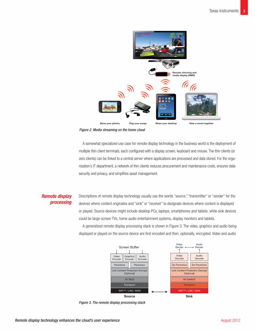
Descriptions of remote display technology usually use the words “source,” “transmitter” or “sender” for the
devices where content originates and “sink” or “receiver” to designate devices where content is displayed
or played. Source devices might include desktop PCs, laptops, smartphones and tablets, while sink devices
could be large-screen TVs, home audio entertainment systems, display monitors and tablets.
A generalized remote display processing stack is shown in Figure 3. The video, graphics and audio being
displayed or played on the source device are first encoded and then, optionally, encrypted. Video and audio
Remote display technology enhances the cloud’s user experience August 2012
Remote display processing
Sink
VideoDecode
AudioDecode
VideoRender
AudioRender
VideoEncode
AudioEncode
Packetize
Link Content Protection Encrypt(Optional)
AV MUX
Transport
Screen Buffer
Source
GraphicsEncode
Packetize De-Packetize
Link Content Protection Decrypt(Optional)
AV DeMUX
Transport
WiFi™ / LAN / WAN
De-Packetize
WiFi™ / LAN / WAN
Figure 3. The remote display processing stack
4 Texas Instruments
are multiplexed together and packetized for transport over a wired or wireless link to the sink device. Here,
the opposite of these processes take place and the content is mirrored on the sink device.
The remote display processing stack presents a number of challenges. For instance, the real-time coding
and decoding algorithms are complex, requiring significant processing power. At the same time, retrofit-
ting a large-screen LCD display for remote display will likely require a small, unobtrusive device that can
be plugged into the display’s HDMI port. Ideally, such a device would be about the size of a thumb drive or
dongle. Consequently, significant processing power would have to be packed into a very compact enclosure.
Certain video and audio compression standards such as the H.264 coder/decoder (codec) have helped in
this regard, but H.264 is only one of several codec standards that are in widespread use. In addition, several
proprietary codecs are prevalent in systems from certain vendors. Moreover, H.264 was intended primarily
as a video processing codec. It may not function as well with other media types, such as text and graphics.
However, H.264 is pervasive and it is particularly critical because it enables high-definition video at low bit
rates.
Power consumption is another important design consideration in some applications of remote display
technology. For instance, a group of thin clients connected to a central server might be powered by power-
over-Ethernet (PoE). The thin clients would need to consume very low power as a result. In another use
case, the sink device might be powered by a low-power Universal Serial Bus (USB) source or a limited power
supply like a battery.
Remote display implementations will also involve other critical considerations stemming from the type of
application and the nature of the content being displayed. For some applications, high-definition imaging and
high-fidelity audio will be of paramount importance, but other types of applications will be able to meet their
use case requirements with less precision.
Content can be classified in four major types or categories: (1) textual and graphical documents such as
Microsoft Word and PowerPoint as well as Adobe PDF (portable document format) files; (2) media such as
video and audio files; (3) games; and (4) web content. As previously mentioned, several codecs are avail-
able for compressing (encoding) and decompressing (decoding) content. Some codecs trade off fidelity or
high-definition for compression efficiency. These are called “lossy” codecs because a portion of the original
content is lost when it is compressed. For example, a lossy codec like H.264 might introduce artifacts into
documents.
Other codecs are referred to as “loss-less.” These codecs retain more of the resolution or precision
of the original media by applying higher order statistics to the content so that less data is lost when it is
compressed and decompressed. The downside to a loss-less codec is its compression efficiency. It may not
compress the content to the extent that a lossy codec will. Each kind of codec offers its own benefits. The
codec implemented in a particular application will depend on the requirements of the use case and the type
Remote display technology enhances the cloud’s user experience August 2012
Codec tradeoffs
5Texas Instruments
of content being displayed. Some applications will require high-definition video and graphics while others will
be more concerned with the amount of bandwidth needed to move or store the content. If bandwidth and
storage space are concerns in a certain application, a lossy compression algorithm that compresses data
more effectively could be more appropriate than a loss-less algorithm, which retains more of the original data
but does not compress the data as compactly.
Several different standard bodies and consortia have addressed the industry’s need for effective codecs. A
few of the more prominent examples are the Digital Living Network Alliance (DLNA), the Wi-Fi™ Alliance and
the Wireless Gigabit Alliance.
The DLNA was founded primarily to enable streaming video and audio. As a result, the group’s standards
do not perform well on web pages. The organization now supports a large number of codecs, although
interoperability among devices supporting the DLNA standards continues to be a challenge. In contrast to
DLNA, the Wi-Fi Alliance’s Wi-Fi Miracast™ standard is much simpler. Its developers hope that this simplic-
ity will overcome many interoperability issues. It is well suited for displaying web pages. In most cases, the
Web page seen on the screen of the source device is accurately rendered on the display of the sink device.
Ultimately, some or all of these codecs will likely be involved in remote display applications. The right codec
will be determined by the requirements of each use case.
Another challenge facing remote display applications will be the simplicity of any wireless communications
connection. Several wireless technologies, including Near Field Communications (NFC), Wi-Fi or one of its
new variants such as Wi-Fi Direct, are candidates to be implemented at the transport/physical layer in the
remote display processing stack. The key will be how easily and seamlessly wireless connectivity can be es-
tablished. A link that is time-consuming or technically challenging to set up will be perceived as an obstacle
Remote display technology enhances the cloud’s user experience August 2012
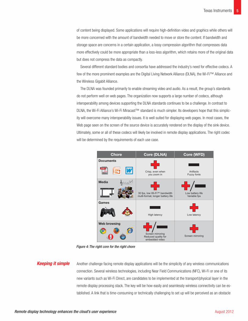
Chore
Documents
Media
Games
Web browsing
Core (DLNA) Core (WFD)
Crisp, even whenyou zoom in
ArtifactsFuzzy fonts
30 fps, low Wi-Fi™ bandwidthmulti-format, longer battery life
Low battery lifeVariable fps
Screen mirroringScreen mirroring
Reduced quality forembedded video
Low latencyHigh latency
Figure 4: The right core for the right chore
Keeping it simple
6 Texas Instruments
for many consumers. Technologies like NFC simplify transport layer communications, enabling two devices to
exchange information with very little human intervention. Establishing a wireless link with NFC can be as easy
as tapping the source device to the sink device.
The adoption of new applications always depends on user demand and enabling technologies. For remote
display technology, both of these factors are emerging at the same time. The final pieces needed for end-
user products will be solutions from companies like TI. Now, TI is applying its powerful system-on-chip (SoC)
processors, including the DaVinci™ DM36x and DM81x video processors, in remote display solutions.
These embedded processors pack the processing power of a complete desktop computer, but can run on a
battery and are available at a cost level that consumers can easily afford.
TI is helping manufacturers develop implementations of remote display technology by providing several
reference design kits (RDKs). The following sections of this white paper offer details on some of TI’s RDKs,
specifically the RDKs that concern remote media display applications of remote display technology for the
infotainment, work and home clouds, and an RDK that addresses thin client applications for the work cloud.
Content sharing via remote display technology can span all three clouds. For the home cloud, remote media
display will involve the sharing of consumer-oriented multimedia, such as movies, photos, music and more.
On the infotainment cloud, multimedia can be streamed from the public Internet and displayed remotely in
order to share the content with others. And lastly, content can be shared on the work cloud in applications
involving networked presentation projectors, digital signage in retail stores and other similar implementations.
TI has designed several RDKs with various options in order to meet the requirements of this broad range of
remote media display applications.
TI’s RDKs for remote media display have incorporated optimized Wi-Fi Miracast™ and DLNA interfaces
specifically for streaming media over either wireless and wired connections. Many of the remote media
display applications involving content on the work cloud may have wired LAN connectivity while consumer
remote media display in the home will likely be dominated by wireless links.
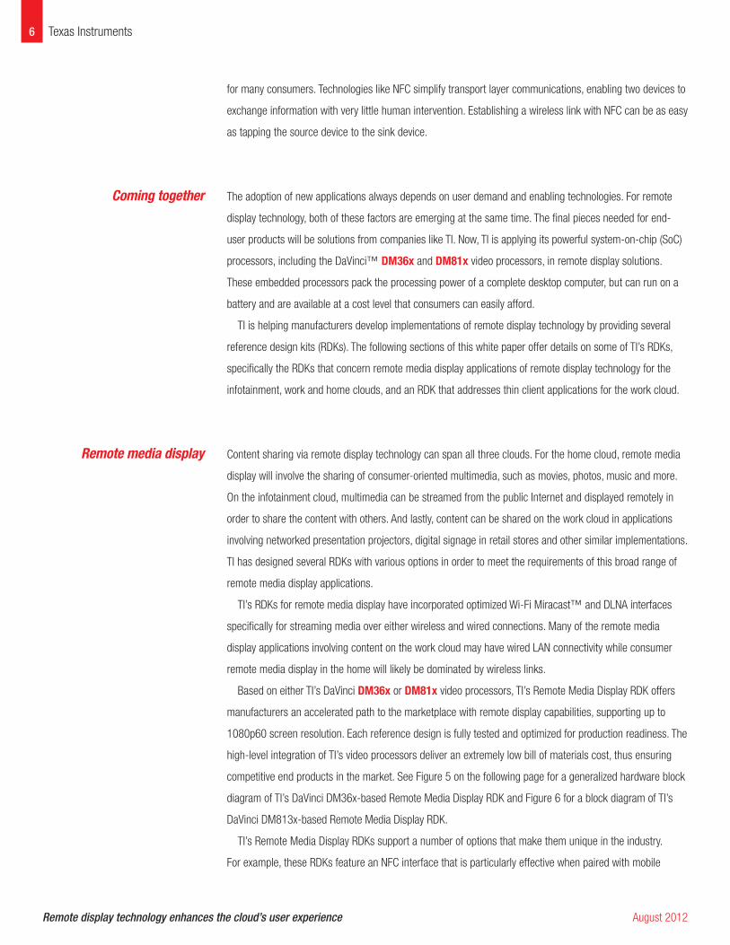
Based on either TI’s DaVinci DM36x or DM81x video processors, TI’s Remote Media Display RDK offers
manufacturers an accelerated path to the marketplace with remote display capabilities, supporting up to
1080p60 screen resolution. Each reference design is fully tested and optimized for production readiness. The
high-level integration of TI’s video processors deliver an extremely low bill of materials cost, thus ensuring
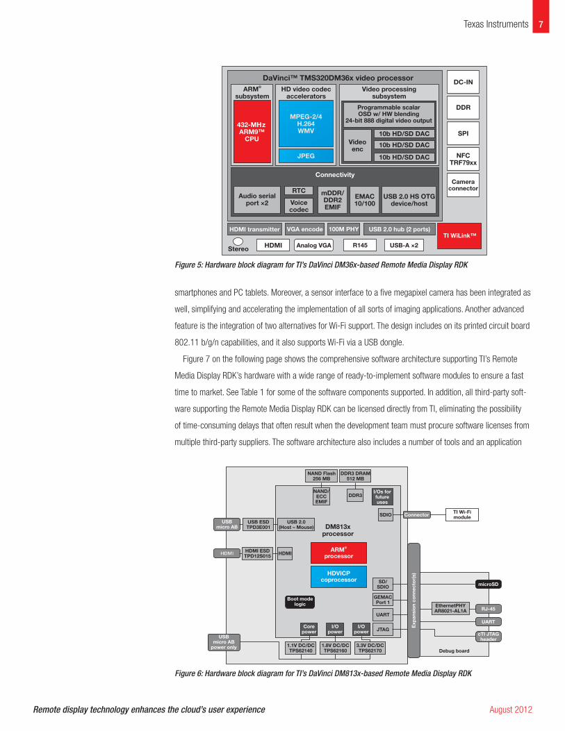
competitive end products in the market. See Figure 5 on the following page for a generalized hardware block
diagram of TI’s DaVinci DM36x-based Remote Media Display RDK and Figure 6 for a block diagram of TI’s
DaVinci DM813x-based Remote Media Display RDK.
TI’s Remote Media Display RDKs support a number of options that make them unique in the industry.
For example, these RDKs feature an NFC interface that is particularly effective when paired with mobile
Remote display technology enhances the cloud’s user experience August 2012
Remote media display
Coming together
7Texas Instruments
smartphones and PC tablets. Moreover, a sensor interface to a five megapixel camera has been integrated as
well, simplifying and accelerating the implementation of all sorts of imaging applications. Another advanced
feature is the integration of two alternatives for Wi-Fi support. The design includes on its printed circuit board
802.11 b/g/n capabilities, and it also supports Wi-Fi via a USB dongle.
Figure 7 on the following page shows the comprehensive software architecture supporting TI’s Remote
Media Display RDK’s hardware with a wide range of ready-to-implement software modules to ensure a fast
time to market. See Table 1 for some of the software components supported. In addition, all third-party soft-
ware supporting the Remote Media Display RDK can be licensed directly from TI, eliminating the possibility
of time-consuming delays that often result when the development team must procure software licenses from
multiple third-party suppliers. The software architecture also includes a number of tools and an application
Remote display technology enhances the cloud’s user experience August 2012
DaVinci™ TMS320DM36x video processor
ARM
subsystem
®
432-MHz
ARM9™
CPU
HD video codec
accelerators
Connectivity
Audio serial
port ×2
HDMI transmitter VGA encode 100M PHY
R145Analog VGA USB-A ×2
TI WiLink™
USB 2.0 hub (2 ports)
MPEG-2/4
H.264
WMV
JPEG
RTC
Voice
codec
mDDR/
DDR2
EMIF
EMAC
10/100
USB 2.0 HS OTG
device/host
DC-IN
DDR
SPI
NFC
TRF79xx
Camera
connector
Video processing
subsystem
10b HD/SD DAC
10b HD/SD DAC
10b HD/SD DACVideo
enc
HDMIStereo
Programmable scalar
OSD w/ HW blending
24-bit 888 digital video output
Figure 5: Hardware block diagram for TI’s DaVinci DM36x-based Remote Media Display RDK
USB
micro AB
HDMIHDMI HDMI
USB ESD
TPD3E001
USB 2.0
(Host – Mouse)
NAND/
ECC
EMIF
NAND Flash
256 MB
DDR3 DRAM
512 MB
DDR3
SDIO
SD/
SDIOmicroSD
RJ-45
Debug board
UART
cTI JTAG
header
ARM
processor
®
DM813x
processor
HDVICP
coprocessor
GEMAC
Port 1
UART
JTAGI/O
power
Boot mode
logic
I/O
power
USB
micro AB
power only
Core
power
TI Wi-Fi
module
I/Os for
future
uses
HDMI ESD
TPD12S015
EthernetPHY
AR8021-AL1A
3.3V DC/DC
TPS62170
1.8V DC/DC
TPS62160
1.1V DC/DC
TPS62140
Connector
Exp
an
sio
n c
on
ne
cto
r(s
)
Figure 6: Hardware block diagram for TI’s DaVinci DM813x-based Remote Media Display RDK
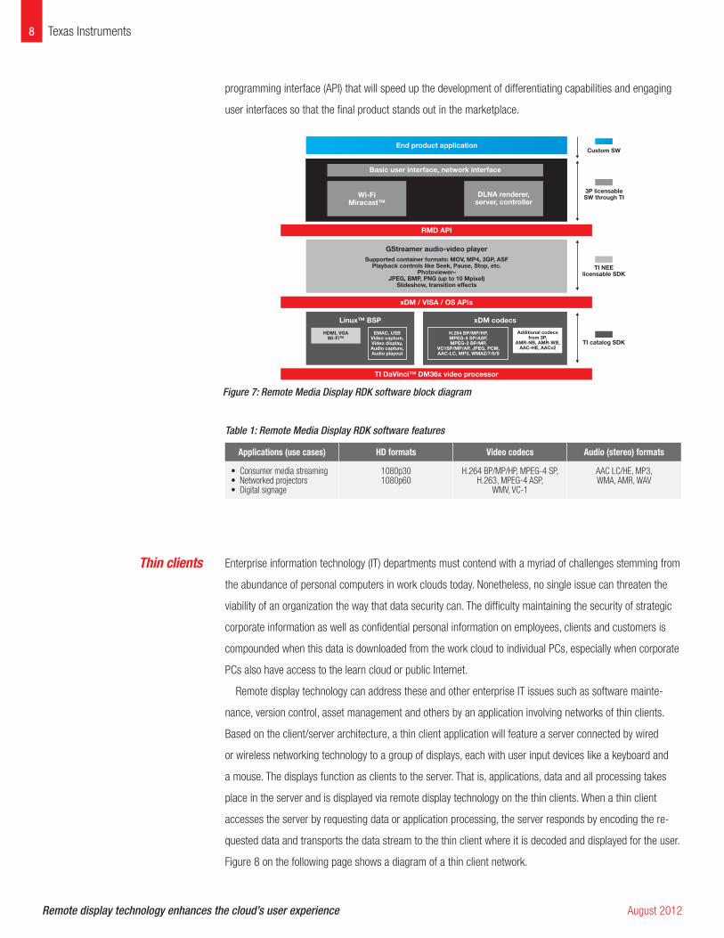
programming interface (API) that will speed up the development of differentiating capabilities and engaging
user interfaces so that the final product stands out in the marketplace.
Table 1: Remote Media Display RDK software features
Applications (use cases) HD formats Video codecs Audio (stereo) formats
• Consumer media streaming • Networked projectors • Digital signage
1080p301080p60
H.264 BP/MP/HP, MPEG-4 SP, H.263, MPEG-4 ASP,
WMV, VC-1
AAC LC/HE, MP3, WMA, AMR, WAV
Enterprise information technology (IT) departments must contend with a myriad of challenges stemming from
the abundance of personal computers in work clouds today. Nonetheless, no single issue can threaten the
viability of an organization the way that data security can. The difficulty maintaining the security of strategic
corporate information as well as confidential personal information on employees, clients and customers is
compounded when this data is downloaded from the work cloud to individual PCs, especially when corporate
PCs also have access to the learn cloud or public Internet.
Remote display technology can address these and other enterprise IT issues such as software mainte-
nance, version control, asset management and others by an application involving networks of thin clients.
Based on the client/server architecture, a thin client application will feature a server connected by wired
or wireless networking technology to a group of displays, each with user input devices like a keyboard and
a mouse. The displays function as clients to the server. That is, applications, data and all processing takes
place in the server and is displayed via remote display technology on the thin clients. When a thin client
accesses the server by requesting data or application processing, the server responds by encoding the re-
quested data and transports the data stream to the thin client where it is decoded and displayed for the user.
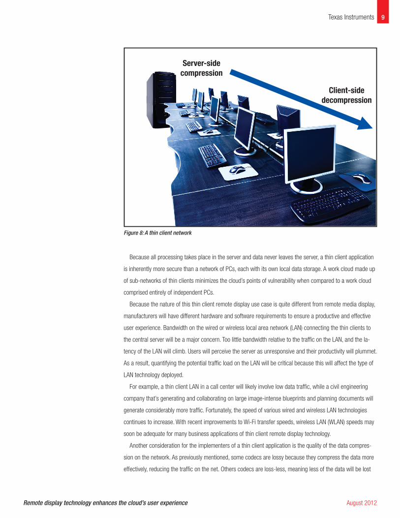
Figure 8 on the following page shows a diagram of a thin client network.
8 Texas Instruments
End product application
Basic user interface, network interface
RMD API
xDM / VISA / OS APIs
TI DaVinci™ DM36x video processor
Linux™ BSP xDM codecs
GStreamer audio-video player
Custom SW
3P licensable
SW through TI
TI NEE
licensable SDK
Supported container formats: MOV, MP4, 3GP, ASF
Playback controls like Seek, Pause, Stop, etc.
Photoviewer–
JPEG, BMP, PNG (up to 10 Mpixel)
Slideshow, transition effects
HDMI, VGA
Wi-Fi™
H.264 BP/MP/HP,
MPEG-4 SP/ASP,
MPEG-2 BP/MP,
VC1SP/MP/AP, JPEG, PCM,
AAC-LC, MP3, WMA2/7/8/9
Additional codecs
from 3P,
AMR-NB, AMR-WB,
AAC-HE, AACv2
EMAC, USB
Video capture,
Video display,
Audio capture,
Audio playout
TI catalog SDK
Wi-Fi
Miracast™
DLNA renderer,
server, controller
Figure 7: Remote Media Display RDK software block diagram
Thin clients
Remote display technology enhances the cloud’s user experience August 2012
Remote display technology enhances the cloud’s user experience August 2012
9Texas Instruments
Because all processing takes place in the server and data never leaves the server, a thin client application
is inherently more secure than a network of PCs, each with its own local data storage. A work cloud made up
of sub-networks of thin clients minimizes the cloud’s points of vulnerability when compared to a work cloud
comprised entirely of independent PCs.
Because the nature of this thin client remote display use case is quite different from remote media display,
manufacturers will have different hardware and software requirements to ensure a productive and effective
user experience. Bandwidth on the wired or wireless local area network (LAN) connecting the thin clients to
the central server will be a major concern. Too little bandwidth relative to the traffic on the LAN, and the la-
tency of the LAN will climb. Users will perceive the server as unresponsive and their productivity will plummet.
As a result, quantifying the potential traffic load on the LAN will be critical because this will affect the type of
LAN technology deployed.
For example, a thin client LAN in a call center will likely involve low data traffic, while a civil engineering
company that’s generating and collaborating on large image-intense blueprints and planning documents will
generate considerably more traffic. Fortunately, the speed of various wired and wireless LAN technologies
continues to increase. With recent improvements to Wi-Fi transfer speeds, wireless LAN (WLAN) speeds may
soon be adequate for many business applications of thin client remote display technology.
Another consideration for the implementers of a thin client application is the quality of the data compres-
sion on the network. As previously mentioned, some codecs are lossy because they compress the data more
effectively, reducing the traffic on the net. Others codecs are loss-less, meaning less of the data will be lost
Client-side
decompression
Server-side
compression
Figure 8: A thin client network
Remote display technology enhances the cloud’s user experience August 2012
10 Texas Instruments
in the compression process and, as a result, the decompressed data is a closer reproduction of the original
data. The price to pay for this fidelity is bandwidth, since the compression algorithm in a loss-less codec
may not be as effective as a lossy codec. Choosing the type of codec for a particular thin client network
should take into consideration the type of applications running on the network. If the quality of the decoded
data displayed by the thin clients does not require high fidelity to the original data, then lossy codecs can be
deployed and data traffic on the network will be reduced. Conversely, if the data displayed by the thin clients
must have high resolution relative to the original data, then loss-less codecs will be chosen and the traffic on
the network will be greater.
Of course, security on any type of LAN is always an important consideration. A thin client network will
require strong security procedures including secure boot and cryptographic measures applied to the data
transferred over the network. At the same time, these measures must not slow down the flow of data or the
application processing taking place on the thin client network as this would lead to a less than satisfactory
user experience. Consequently, hardware-accelerated security measures, including cryptographic algorithms,
will be critical on most thin client remote display deployments.
Other capabilities, such as support for dual-user monitors and the ability to redirect data to a remote
display without encoding by the server will also be required in certain thin client networks.
TI’s Thin Client RDK features the highly integrated DaVinci DM8148 video processor. By blending the
processing power of both an ARM® general-purpose core and a digital signal processing (DSP) core, the
DM8148 processor provides all of the capabilities needed to support the many different types of thin client
deployments which will inevitably have a variety of requirements. For example, the programmability of the
DSP core allows practically any codec to be deployed. As a result, designers can choose the lossy or loss-less
codec that best meets the needs of a certain thin client application. TI’s Thin Client RDK is unique in the industry
in that it supports all of the major open industry-standard codecs as well as the major proprietary codecs.
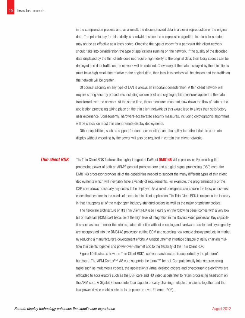
The hardware architecture of TI’s Thin Client RDK (see Figure 9 on the following page) comes with a very low
bill of materials (BOM) cost because of the high level of integration in the DaVinci video processor. Key capabili-
ties such as dual-monitor thin clients, data redirection without encoding and hardware-accelerated cryptography
are incorporated into the DM8148 processor, cutting BOM and speeding new remote display products to market
by reducing a manufacturer’s development efforts. A Gigabit Ethernet interface capable of daisy chaining mul-
tiple thin clients together and power-over-Ethernet add to the flexibility of the Thin Client RDK.
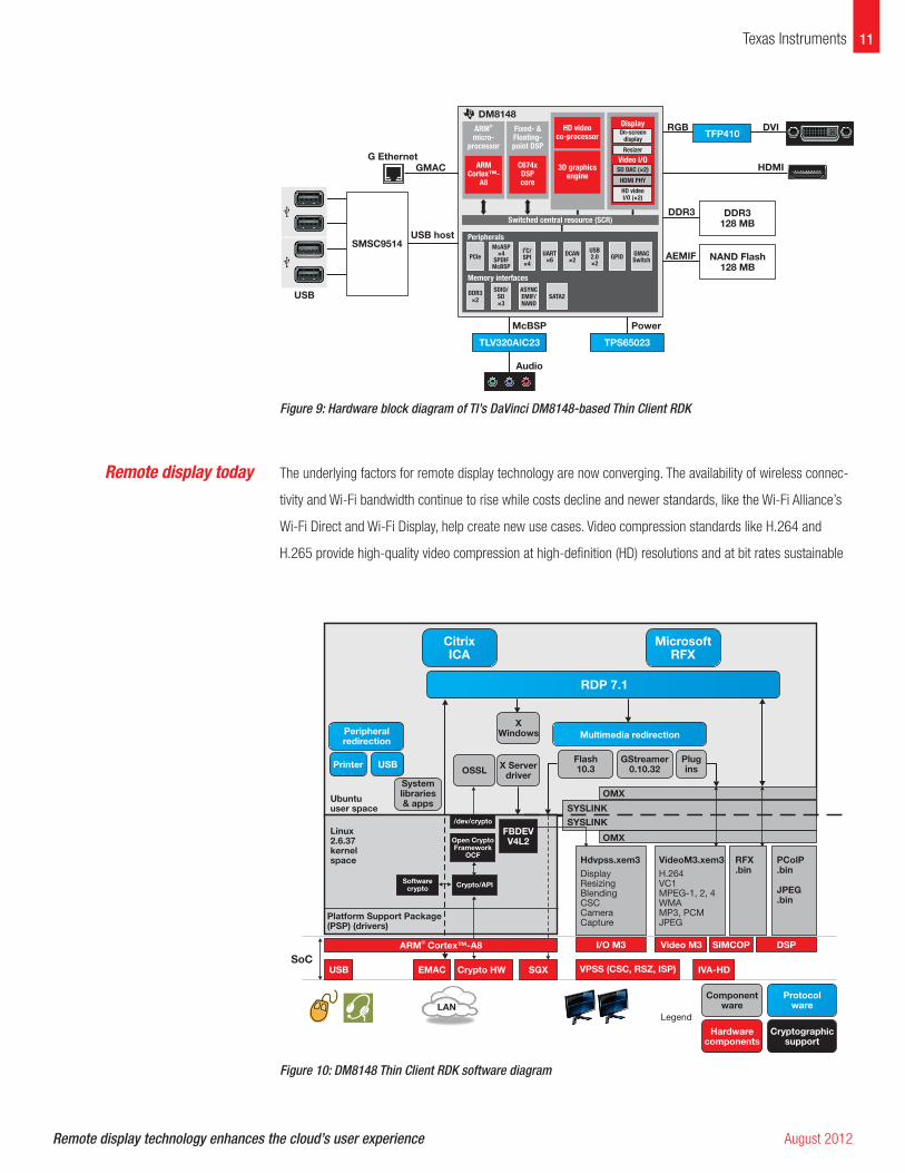
Figure 10 illustrates how the Thin Client RDK’s software architecture is supported by the platform’s
hardware. The ARM Cortex™-A8 core supports the Linux™ kernel. Computationally intense processing
tasks such as multimedia codecs, the application’s virtual desktop codecs and cryptographic algorithms are
offloaded to accelerators such as the DSP core and HD video accelerator to retain processing headroom on
the ARM core. A Gigabit Ethernet interface capable of daisy chaining multiple thin clients together and the
low-power device enables clients to be powered-over-Ethernet (POE).
Thin client RDK
Remote display technology enhances the cloud’s user experience August 2012
11Texas Instruments
USB
SMSC9514
G Ethernet
GMAC
USB host
RGB
DDR3
AEMIF
PowerMcBSP
Audio
DVI
HDMI
DM8148
Fixed- &Floating-point DSP
C674xDSPcore
HD videoco-processor
Peripherals
PCIe
DDR3×2
SATA2SDIO/
SD×3
ASYNCEMIF/NAND
McASP×4
SPDIFMcBSP
I C/SPI×4
2
UART×6
DCAN×2
USB2.0×2
GPIOGMACSwitch
Memory interfaces
3D graphicsengine
ARMCortex™-
A8
ARMmicro-
processor
®
TLV320AIC23 TPS65023
TFP410
Switched central resource (SCR)
Display
Video I/O
On-screendisplay
Resizer
SD DAC (×2)
HDMI PHY
HD videoI/O (×2)
DDR3
128 MB
NAND Flash
128 MB
Figure 9: Hardware block diagram of TI’s DaVinci DM8148-based Thin Client RDK
The underlying factors for remote display technology are now converging. The availability of wireless connec-
tivity and Wi-Fi bandwidth continue to rise while costs decline and newer standards, like the Wi-Fi Alliance’s
Wi-Fi Direct and Wi-Fi Display, help create new use cases. Video compression standards like H.264 and
H.265 provide high-quality video compression at high-definition (HD) resolutions and at bit rates sustainable
Microsoft
RFX
Citrix
ICA
RDP 7.1
Multimedia redirection
X
Windows
OSSL
System
libraries
& apps
Peripheral
redirection
Printer USBFlash
10.3
GStreamer
0.10.32
Plug
ins
OMX
OMX
I/O M3
VPSS (CSC, RSZ, ISP)SGXCrypto HWEMAC
Platform Support Package
(PSP) (drivers)
Linux
2.6.37
kernel
space
Ubuntu
user space
USB
SoC
IVA-HD
Component
ware
Hardware
components
Protocol
ware
Cryptographic
support
Video M3 SIMCOP DSP
Hdvpss.xem3 VideoM3.xem3 RFX
.bin
PColP
.bin
JPEG
.bin
DisplayResizingBlendingCSCCameraCapture
H.264VC1MPEG-1, 2, 4WMAMP3, PCMJPEG
SYSLINK
SYSLINK
X Server
driver
FBDEV
V4L2
/dev/crypto
Crypto/APISoftware
crypto
Open Crypto
Framework
OCF
ARM Cortex™-A8®
LAN
Legend
Figure 10: DM8148 Thin Client RDK software diagram
Remote display today
SPRY210© 2012 Texas Instruments Incorporated
Important Notice: The products and services of Texas Instruments Incorporated and its subsidiaries described herein are sold subject to TI’s standard terms and conditions of sale. Customers are advised to obtain the most current and complete information about TI products and services before placing orders. TI assumes no liability for applications assistance, customer’s applications or product designs, software performance, or infringement of patents. The publication of information regarding any other company’s products or services does not constitute TI’s approval, warranty or endorsement thereof.
Code Composer Studio and DaVinci are trademarks of Texas Instruments Incorporated. All other trademarks are the property of their respective owners.
on wireless links. Consumer demand for thin, small devices such as smartphones, tablets and ultra-thin lap-
tops has eliminated many of the familiar connectors like VGA and HDMI that were typical of user devices in
the past. This has accelerated the need for alternative wireless connectivity solutions to devices where cloud
content can be shared and appreciated to its fullest, such as the large-screen HD displays that are becoming
so commonplace. The answer to this situation is remote display technology.
TI’s Remote Media Display and Thin Client RDKs accelerate a manufacturer’s time to market with remote
display products that can be implemented today. The range of capabilities integrated in TI’s DaVinci video
processors ensures a flexible remote display platform capable of easy configuration and able to meet the
particular needs of unique use cases.
12 Texas Instruments

IMPORTANT NOTICE
Texas Instruments Incorporated and its subsidiaries (TI) reserve the right to make corrections, enhancements, improvements and otherchanges to its semiconductor products and services per JESD46C and to discontinue any product or service per JESD48B. Buyers shouldobtain the latest relevant information before placing orders and should verify that such information is current and complete. Allsemiconductor products (also referred to herein as “components”) are sold subject to TI’s terms and conditions of sale supplied at the timeof order acknowledgment.
TI warrants performance of its components to the specifications applicable at the time of sale, in accordance with the warranty in TI’s termsand conditions of sale of semiconductor products. Testing and other quality control techniques are used to the extent TI deems necessaryto support this warranty. Except where mandated by applicable law, testing of all parameters of each component is not necessarilyperformed.
TI assumes no liability for applications assistance or the design of Buyers’ products. Buyers are responsible for their products andapplications using TI components. To minimize the risks associated with Buyers’ products and applications, Buyers should provideadequate design and operating safeguards.
TI does not warrant or represent that any license, either express or implied, is granted under any patent right, copyright, mask work right, orother intellectual property right relating to any combination, machine, or process in which TI components or services are used. Informationpublished by TI regarding third-party products or services does not constitute a license to use such products or services or a warranty orendorsement thereof. Use of such information may require a license from a third party under the patents or other intellectual property of thethird party, or a license from TI under the patents or other intellectual property of TI.
Reproduction of significant portions of TI information in TI data books or data sheets is permissible only if reproduction is without alterationand is accompanied by all associated warranties, conditions, limitations, and notices. TI is not responsible or liable for such altereddocumentation. Information of third parties may be subject to additional restrictions.
Resale of TI components or services with statements different from or beyond the parameters stated by TI for that component or servicevoids all express and any implied warranties for the associated TI component or service and is an unfair and deceptive business practice.TI is not responsible or liable for any such statements.
Buyer acknowledges and agrees that it is solely responsible for compliance with all legal, regulatory and safety-related requirementsconcerning its products, and any use of TI components in its applications, notwithstanding any applications-related information or supportthat may be provided by TI. Buyer represents and agrees that it has all the necessary expertise to create and implement safeguards whichanticipate dangerous consequences of failures, monitor failures and their consequences, lessen the likelihood of failures that might causeharm and take appropriate remedial actions. Buyer will fully indemnify TI and its representatives against any damages arising out of the useof any TI components in safety-critical applications.
In some cases, TI components may be promoted specifically to facilitate safety-related applications. With such components, TI’s goal is tohelp enable customers to design and create their own end-product solutions that meet applicable functional safety standards andrequirements. Nonetheless, such components are subject to these terms.
No TI components are authorized for use in FDA Class III (or similar life-critical medical equipment) unless authorized officers of the partieshave executed a special agreement specifically governing such use.
Only those TI components which TI has specifically designated as military grade or “enhanced plastic” are designed and intended for use inmilitary/aerospace applications or environments. Buyer acknowledges and agrees that any military or aerospace use of TI componentswhich have not been so designated is solely at the Buyer's risk, and that Buyer is solely responsible for compliance with all legal andregulatory requirements in connection with such use.
TI has specifically designated certain components which meet ISO/TS16949 requirements, mainly for automotive use. Components whichhave not been so designated are neither designed nor intended for automotive use; and TI will not be responsible for any failure of suchcomponents to meet such requirements.
Products Applications
Audio www.ti.com/audio Automotive and Transportation www.ti.com/automotive
Amplifiers amplifier.ti.com Communications and Telecom www.ti.com/communications
Data Converters dataconverter.ti.com Computers and Peripherals www.ti.com/computers
DLP® Products www.dlp.com Consumer Electronics www.ti.com/consumer-apps
DSP dsp.ti.com Energy and Lighting www.ti.com/energy
Clocks and Timers www.ti.com/clocks Industrial www.ti.com/industrial
Interface interface.ti.com Medical www.ti.com/medical
Logic logic.ti.com Security www.ti.com/security
Power Mgmt power.ti.com Space, Avionics and Defense www.ti.com/space-avionics-defense
Microcontrollers microcontroller.ti.com Video and Imaging www.ti.com/video
RFID www.ti-rfid.com
OMAP Mobile Processors www.ti.com/omap TI E2E Community e2e.ti.com
Wireless Connectivity www.ti.com/wirelessconnectivity
Mailing Address: Texas Instruments, Post Office Box 655303, Dallas, Texas 75265Copyright © 2012, Texas Instruments Incorporated