REMOTE CONDITION MONITORING SYSTEM FOR A HYBRID … · remote condition monitoring system for a...
11
REMOTE CONDITION MONITORING SYSTEM FOR A HYBRID WIND-DIESEL SYSTEM—APPLICATION AT FERNANDO DE NORONHA ISLAND, BRAZIL Gustavo de Novaes Pires Leite 2 Brazilian Wind Energy Centre, Brazil 1 [email protected] Everaldo Alencar Feitosa 1 Brazilian Wind Energy Centre, Brazil 2 [email protected] Andrea G. Kraj 3 University of Manitoba, Canada 3 [email protected] Abstract The Brazilian Wind Energy Centre, has instrumented a 225 kW wind turbine (rotor diameter: 30 m, tower height: 30 m) connected to the electrical grid with an intelligent CMS. The wind turbine is located on the island of Fernando de Noronha (FDN) belonging to the state of Pernambuco, located 525 km off the coast of Brazil in the South Atlantic Ocean. The island is an ecological reserve with a remote community strongly dependent on the energy supply from this turbine. The wind turbine provides approximately 8% - 10% of the annual energy consumption on the island while the diesel system provides the remainder. Failures of the gearbox, bearings and the occurrence of resonance are a major concern for operators and maintance staff of wind farms, as for the community that is dependent on the provided energy supply, especially in remote locations. Previous investigation has shown that premature failure of these components can abruptly reduce the profit of the wind farm or even damage a whole wind turbine if such a failure is not detected, inhibiting a reliable energy supply and jeopardizing the security of essential needs in remote communities where critical loads, such as hospitals and water desalination plants are more dependent on the energy supply than in larger communities with greater energy reserves. The CMS supervises the vibration pattern from the tower, generator, main bearing and gearbox in order to detect potential failure that could occur in the wind turbine. The use of condition monitoring systems (CMS) is advised by insurance companies for wind farm operators in order to reduce turbine downtime, increase profits and reduce maintenance costs of wind farms, which often can reach 25% of the overall wind farm costs. This technology provides a reasonable time for planning maintenance and executing corrective actions, reducing turbine downtime and securing energy supply. This paper documents the actual data recorded by the CMS from the accelerometers installed inside the nacelle measuring the vibration occuring in the gearbox, main bearing, generator and tower. These results are compared to industry standards to provide an indication of the current operating state of the wind turbine. Keywords: Condition monitoring system, predictive maintenance, vibration analysis, spectrum analysis, wind turbine.
Transcript of REMOTE CONDITION MONITORING SYSTEM FOR A HYBRID … · remote condition monitoring system for a...

REMOTE CONDITION MONITORING SYSTEM FOR A HYBRID WIND-DIESEL SYSTEM—APPLICATION AT FERNANDO DE NORONHA ISLAND, BRAZIL
Gustavo de Novaes Pires Leite2
Brazilian Wind Energy Centre, Brazil [email protected]
Everaldo Alencar Feitosa1
Brazilian Wind Energy Centre, Brazil [email protected]
Andrea G. Kraj3
University of Manitoba, Canada [email protected]
Abstract
The Brazilian Wind Energy Centre, has instrumented a 225 kW wind turbine (rotor diameter: 30 m, tower height: 30 m) connected to the electrical grid with an intelligent CMS. The wind turbine is located on the island of Fernando de Noronha (FDN) belonging to the state of Pernambuco, located 525 km off the coast of Brazil in the South Atlantic Ocean. The island is an ecological reserve with a remote community strongly dependent on the energy supply from this turbine. The wind turbine provides approximately 8% - 10% of the annual energy consumption on the island while the diesel system provides the remainder.
Failures of the gearbox, bearings and the occurrence of resonance are a major concern for operators and maintance staff of wind farms, as for the community that is dependent on the provided energy supply, especially in remote locations. Previous investigation has shown that premature failure of these components can abruptly reduce the profit of the wind farm or even damage a whole wind turbine if such a failure is not detected, inhibiting a reliable energy supply and jeopardizing the security of essential needs in remote communities where critical loads, such as hospitals and water desalination plants are more dependent on the energy supply than in larger communities with greater energy reserves.
The CMS supervises the vibration pattern from the tower, generator, main bearing and gearbox in order to detect potential failure that could occur in the wind turbine. The use of condition monitoring systems (CMS) is advised by insurance companies for wind farm operators in order to reduce turbine downtime, increase profits and reduce maintenance costs of wind farms, which often can reach 25% of the overall wind farm costs. This technology provides a reasonable time for planning maintenance and executing corrective actions, reducing turbine downtime and securing energy supply. This paper documents the actual data recorded by the CMS from the accelerometers installed inside the nacelle measuring the vibration occuring in the gearbox, main bearing, generator and tower. These results are compared to industry standards to provide an indication of the current operating state of the wind turbine. Keywords: Condition monitoring system, predictive maintenance, vibration analysis, spectrum analysis, wind turbine.

INTRODUCTION
When a wind turbine is located in a remote location, access to the site may be difficult and maintenance of the system will be dependent on the ability to access the site. Should a problem or failure occur, the operation down-time can lead to significant economic losses and lack of power supply in a remote system with critical loads can significantly affect the well-being of those dependent on the energy system.
As the size of wind turbines increases continuously, business economics dictate careful management of equipment in order to:
1. Minimize downtime; 2. Maximize availability and profits; 3. Reduce the maintenance cost which often represents around 25 % of the
wind farm maintenance. Furthermore, these machines are often remotely located and immediate
access to effected machinery is restricted due to its location at the top of the towers (usually above 100 meters a.g.l), limiting regular manual maintenance. Therefore small problems such as a bearing that needs to be replaced go undetected and progress to large failure.
Remote condition monitoring systems are used to monitor the condition of critical operating major components of the wind turbine, such as the gearbox, generator, main bearings and tower. The CMS provides a continuous indication of the health of the components based on vibration analysis using accelerometers and the Fast Fourier Transform (FFT), Envelope and Cepstrum Analysis. HYBRID WIND-DIESEL SYSTEM AT FERNANDO DE NORONHA ISLAND
The Fernando de Noronha Archipelago is situated four degrees below the Equator line, at 3º54' S latitude and 32º25' W longitude. The distance to Recife, capital of the State of Pernambuco, Brazil, is 525 km. The Archipelago is formed by the mountain peaks of a volcanic cordillera, and composed of 21 islands, cliffs and islets with a total area of about 26 km².
Figure 1 shows the Archipelago of Fernando de Noronha. FDN experiences constant winds with predominant SE direction and average
speed of 9.0 m/s which indicates a very good potential to be explored. The current population on the island of Fernando de Noronha consists of 3000
inhabitants, of which approximately 50% are tourists. These inhabitants rely on the diesel and wind power systems on the island to provide energy. The vital loads on the island include the desalination plant and hospital. The hospital and school are both supported by independent PV energy systems for backup power.
The current averaged annual energy consumption of 9,020.5 MWh is split between 8% wind energy and 92% diesel generated power. Table 1 summarizes the annual energy consumption averaged over year 2005 to 2007. PREDICTIVE MAINTENANCE
In the early years of the mechanical industry corrective maintenance was introduced. The basic philosophy of this kind of maintenance is to allow the machinery to run to failure and only repair or replace damaged components just before or when the equipment comes to a complete stop. From simple understanding

of this philosophy it is evident that this method is not a sophisticated practice for the maintenance of wind farms. The main disadvantage of this system is that the maintenance crew operates in an unplanned mode which is contradictory to the optimal operation of a wind farm, which should not be stopped in an unplanned way due to the high costs associated with correctional actions and huge losses in production.
The preventive maintenance is what has been largely used by the O & M wind farm personnel. The philosophy behind preventive maintenance is to schedule maintenance activities at predetermined time intervals based on calendar days or runtime hours of machine operation. In this case, the repair or replacements of damaged equipments is carried out before obvious problems occur. The main disadvantage is that scheduled maintenance can result in performing maintenance tasks too early or too late.
The predictive maintenance system, using vibration analysis, is a powerful technique employed to determine the operational conditions at any point in time of given equipment, such as a wind turbine. The main advantage of this methodology is to permit previous identification of developing failures before those failures become serious problems in the machinery. It is achieved by continuous condition monitoring of such a machine.
Figure 2 shows the main problems likely to occur in a wind turbine. The majority of the problems presented in the following figure do not show any symptoms that can be normally perceived by the human senses. When such a symptom is detected, it is shown in the form of vibration and it is considerably difficult to identify the source and the severity of the vibration. Thus, it is critical to identify the proper placement for installation of the accelerometers (vibration sensors) in order to identify the source and the severity of the vibration signal appropriately.
Figure 3 shows the measurement chain necessary for carrying out a predictive maintenance analysis through a condition monitoring system.
Briefly, the vibration signal is transmitted to the sensor (accelerometer) and after that is amplified by the amplifier. Digital filters select the setup band frequencies and the signal is sent to the analyzer. This component calculates the vibration spectrums (FFT, Envelope and Cepstrum) and the resultant signal is stored in a data bank. Then, the vibration data is displayed and further analyzed by a specialist. METHODOLOGY Vestas V27 225 kW Wind Turbine
The wind turbine used for this case study was a Vestas V27 Wind Turbine 225 kW installed in the test centre of the Brazilian Wind Energy Institute, in Fernando de Noronha, Brazil (see Figure 4). All accelerometers and analysis module were installed inside the wind turbine.
The main characteristics of this wind turbine are presented in the Table 2.

Condition Monitoring System Components Description Vibration Monitor
The vibration monitor is a 2-4 channel digital vibration and process information
monitor intended for stand alone operation. Signal processing is based on embedded FFT-technology, comprising Real Time 800 line Full Zoom FFT, Envelope FFT and Cepstrum.
Individual alarms based on intelligent information from up to 192 different machine components can be sent directly to the machine controller or control centre using industrial communication standards.
Vibration Analysis Software The vibration analysis software is the web-based control, database and display software used to configure the monitor and store downloaded information. If connected on-line with the monitor the software can send status and alarm reports over the Internet, including SMS (short message service). All the control functions, e.g. changing set-ups or viewing spectra, can be performed online via Internet.
Multi-Purpose Accelerometer
In order to analyze a wide frequency range a multi-purpose accelerometer (0.5 Hz to 15 000 Hz) with resonance near 23 kHz was used in the measurement chain. This sensor has a sensitivity of 100 mV/g and temperature range from -50ºC to 121ºC. This sensor is stud mounted on the components of the wind turbine. This accelerometer was used to measure the acceleration / vibration coming from the main bearing, gearbox and generator. Low Frequency Accelerometer The low frequency accelerometer has operational frequency range from 0.16 Hz to 2500 Hz with resonance near 15 kHz. This sensor has a sensitivity of 500 mV/g and temperature range from -51ºC to 121ºC. This sensor is stud mounted on the components of the wind turbine. This accelerometer was used to measure the acceleration / vibration coming from the tower. Sensors Layout
Figure 5 shows the sensors layout inside the nacelle of the Vestas V27 wind
turbine. International Standards and Guidelines (ALLIANZ 2003) have been used to select the sensors capabilities and the components that should be monitored.
Table 3 presents a summary of the condition monitoring system showing the accelerometer type selected for each monitored component as well as the direction and orientation in which each sensor was installed and the objective for the monitoring of each component.

Operational Mode
Figure 6 depicts the mode of operation of the CMS installed in the Vestas V27 in the Island of Fernando de Noronha.
The accelerometers pick up the vibration signal from the monitored components. These signals are transmitted to the vibration monitor where they are amplified and then filtered. The vibration analysis software receives the treated signal according to the user configurations and then executes all the analyses defined for each sensor. Different analyses can be executed by the software, such as: FFT spectrum, Envelope Spectrum, Cepstrum Spectrum and Trending Analysis.
The vibration analysis software works continuously and can be operated remotely via Internet. Then, if an alert condition or failure is detected, the software can send a message by SMS or email to the maintenance staff, or even, turn-off the wind turbine if the detected condition is set to require this action. RESULTS
This section presents the analysis of the vibration signal picked up by the CMS installed in the Vestas V27 in the Island of Fernando de Noronha.
Figure 7 shows the FFT spectrum of the gearbox in the horizontal direction. It
is possible to see relevant peaks in the frequency range from 500 Hz to 1000 Hz. The peaks in this region are related to resonance problems on the bearing elements due to the impact of the rolling elements. It represents an important statement and requires a deeper investigation which will be carried out further.
Figure 7 shows also a peak at 340 Hz. This is the gear mesh frequency of the high speed train. This is an important peak because it represents the condition of the gears and since this peak becomes relevant, it indicates problems on some gears. This peak is relatively small compared to the high frequency peaks; even so, it is continuously evaluated.
Figure 8 presents the FFT spectrum of the main bearing of the low speed shaft. It is possible to identify with harmonic cursors that the peak at 3X is more relevant than the peak at 1X. This is due to the blade passing frequency phenomenon. The 1X and 3X excitation frequencies are prone to cause resonance if the vibration modes of the turbine tower are near the 1X and 3X frequencies. Modal analysis tests will be further carried out in order to evaluate the natural frequency of the tower.
In addition, a relevant peak can be noted at 20 Hz. This peak is the gear mesh frequency of the low speed train. Thereby, the condition of the low speed gear train needs to be further analyzed.

CONCLUSION
This work presented the development and installation of a condition monitoring system for large wind turbines in remote communities by using the vibration analysis. The actual status of the system as well as installation aspects of the condition monitoring system was presented.
The results section presented conclusive aspects about the condition of the low speed gear train, tower frequencies and bearings mounted on the high speed shaft of the gearbox.
Thus, the Vestas V27 wind turbine clearly needs to be subjected to a complete overhaul to evaluate the actual condition of the suspect components in order to avoid unexpected failure in the future and maintain reliable operation for its community. REFERENCES ALLIAZ ZENTRUM FÜR TECHNIK GmbH, Anforderungen an Condition Monitoring Systeme für Windenergieanlagen; Report N° 03.01.068, 2003. BECKER, E., POSTE, P., Keeping the Blades Running, Refocus, 2006. Brüel & Kjaer, Lecture Note: Vibration Transducer and Signal Conditioning, Naerum-Dinamarca, Brüel & Kjaer, 1998. CASELITZ, P. et al, On-line Fault Detection and Prediction in Wind Energy Converts, Thessaloniki, 1994. KARDEC, A., NASCIF, N., Manutenção: Função Estratégica, Rio de Janeiro, Qualitymark Ed., 2001. PCH, PCH 5011: Survey and Diagnostic System, 2005.

FIGURES AND TABLES
Figure 1 – Archipelago of Fernando de Noronha.
Figure 2 - Probable failures of a wind turbine.
- Wear, pitting, deformation of outer/inner race and rolling elements of bearings - Fatigue, cracks
- Surface roughness - Imbalance - Fatigue, cracks - Clearance - Faults in the pitch system
- Gear eccentricity - Tooth wear - Inadequate lubrication - Misalignment
- Resonance - Fatigue, cracks
- Yaw angle offset
- Electrical asymmetries - Phase imbalance - Overheating
Yaw system
Tower
Gearbox
Rotor
Shaft, bearings
Generator

Figure 3 - Measurement chain.
Figure 4 – Vestas V27 – 225 kW Wind Turbine.
Amplifier
Filter(s)
Sensor Analyzer Recorder
Output
x1
x2
t
Hz
Analyzer PC

Figure 5 – Sensors layout.
Figure 6 – Condition Monitoring System Mode of Operation.
Gearbox Horizontal direction
Main bearing Vertical direction
Generator Vertical direction
Generator Horizontal direction
Main bearing Horizontal direction
Gearbox Vertical direction
Tower In the direction of
the prevailing wind Tower
90° out of the direction of the prevailing wind
DATA BANK
TOWER
GENERATOR
GEARBOX
MAIN BEARING
MO
NIT
OR
ING
SYS
TEM
ALARM
WIND TURBINE

Figure 7 – FFT spectrum of the gearbox in the horizontal direction.
Figure 8 – FFT spectrum of the main bearing in the horizontal direction.
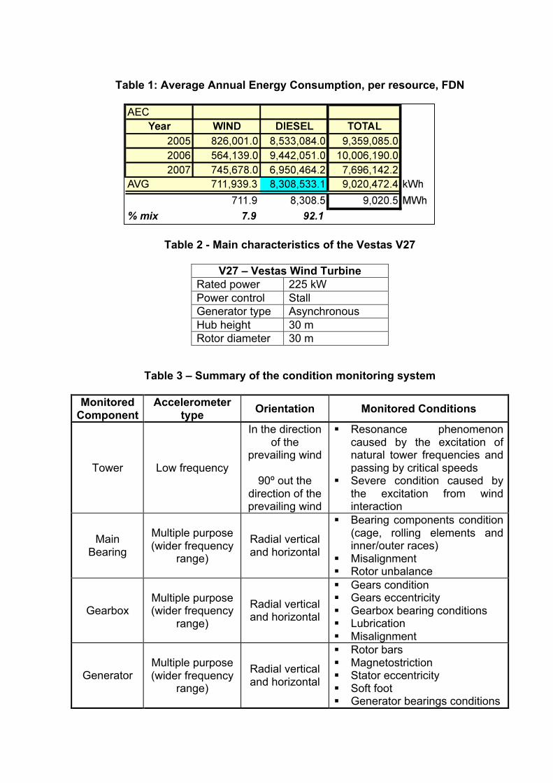
Table 1: Average Annual Energy Consumption, per resource, FDN
Table 2 - Main characteristics of the Vestas V27
V27 – Vestas Wind Turbine
Rated power 225 kW Power control Stall Generator type Asynchronous Hub height 30 m Rotor diameter 30 m
Table 3 – Summary of the condition monitoring system
Monitored Component
Accelerometer type Orientation Monitored Conditions
Tower Low frequency
In the direction of the
prevailing wind
90º out the direction of the prevailing wind
Resonance phenomenon caused by the excitation of natural tower frequencies and passing by critical speeds
Severe condition caused by the excitation from wind interaction
Main Bearing
Multiple purpose (wider frequency
range)
Radial vertical and horizontal
Bearing components condition (cage, rolling elements and inner/outer races)
Misalignment Rotor unbalance
Gearbox Multiple purpose (wider frequency
range)
Radial vertical and horizontal
Gears condition Gears eccentricity Gearbox bearing conditions Lubrication Misalignment
Generator Multiple purpose (wider frequency
range)
Radial vertical and horizontal
Rotor bars Magnetostriction Stator eccentricity Soft foot Generator bearings conditions