REMOTE AND SEMI-AUTOMATED OPERATION OF AN · PDF fileREMOTE AND SEMI-AUTOMATED OPERATION OF AN...
16
REMOTE AND SEMI-AUTOMATED OPERATION OF AN ELECTRIC CABLE SHOVEL AUTHOR Garston H. Blackwell, Prof. of Mining Engineering, Buchan School of Mining, Queens University, Kingston, Ontario, Canada. Phone +01 613 533 2204, e-mail [email protected] ABSTRACT For ageing open pit mining operations where the economic viability of another pushback is questionable, mine life can be extended by increasing the wall slope. If the steepening is started where ore intersects the pit wall, the capital outlay for waste stripping is minimal. Such a venture must be conducted safely, and a basic requirement would include loading equipment capable of working remotely. In the application described, alternatives in the choice of loader included equipment available on site, or the purchase and assembly of used equipment. Only electric cable shovels were in use at the operation, and it was thought that these would be more capable of digging high muck piles at the productivity demanded by an increasingly efficient mill, and in a challenging environment less suited to a rubber tired loader or hydraulic front shovel. A decision was made to convert an older electric cable shovel to remote controlled operation and to include the application of semi-robotic control. The conversion was completed successfully and is described, along with methods developed for remote operation of a shovel, and the application of various sensors for semi-robotic operation. A plan of operations to mine out several completed double benches and make two quadruple benches with wide catchment berms is depicted. On completion of this task, the working benches developed would be wide enough to operate at near full production. Prior to moving the remote controlled shovel back into the pit, a large wall instability became active, eventually closing the operation. The instability could have been safely mined using the remote controlled shovel. Keywords cable shovel, remote control, sensors (rotation/crowd/hoist/propel), safety INTRODUCTION The electrical cable shovel continues to be the primary loader of choice for large open pit mines. Although initially costly, these machines have the productivity, ruggedness, and longevity required by mining operations to reliably load broken rock into large trucks for haulage to processing plants, waste dumps and leach pads over the life of an operation. The productivity and unit cost efficiency demanded of the mining industry has resulted in substantial increases in truck and shovel size. Shovel and truck capacities have grown 10 fold in the past 50 years. In the 1960’s a typical shovel with a 4.5m 3 bucket would load 30 tonne trucks, and has been replaced by machines with as large as a 60m 3 bucket loading trucks of 350 tonnes. The safe operation of shovels, and mine profitability, is impacted by wall slope angles, and the stability of such walls cannot be guaranteed. Instabilities represent a severe safety hazard, and can involve as little as 5000 tonnes of material above a single 15 meter high working bench, or exceed 15 million tonnes when including material 300m or more up to the pit crest.
Transcript of REMOTE AND SEMI-AUTOMATED OPERATION OF AN · PDF fileREMOTE AND SEMI-AUTOMATED OPERATION OF AN...

REMOTE AND SEMI-AUTOMATED OPERATION OF AN ELECTRIC CABLE SHOVEL
AUTHOR
Garston H. Blackwell, Prof. of Mining Engineering, Buchan School of Mining, Queens
University, Kingston, Ontario, Canada. Phone +01 613 533 2204, e-mail [email protected]
ABSTRACT
For ageing open pit mining operations where the economic viability of another pushback is
questionable, mine life can be extended by increasing the wall slope. If the steepening is started where ore
intersects the pit wall, the capital outlay for waste stripping is minimal. Such a venture must be conducted
safely, and a basic requirement would include loading equipment capable of working remotely.
In the application described, alternatives in the choice of loader included equipment available on
site, or the purchase and assembly of used equipment. Only electric cable shovels were in use at the
operation, and it was thought that these would be more capable of digging high muck piles at the
productivity demanded by an increasingly efficient mill, and in a challenging environment less suited to a
rubber tired loader or hydraulic front shovel. A decision was made to convert an older electric cable shovel
to remote controlled operation and to include the application of semi-robotic control.
The conversion was completed successfully and is described, along with methods developed for
remote operation of a shovel, and the application of various sensors for semi-robotic operation. A plan of
operations to mine out several completed double benches and make two quadruple benches with wide
catchment berms is depicted. On completion of this task, the working benches developed would be wide
enough to operate at near full production.
Prior to moving the remote controlled shovel back into the pit, a large wall instability became
active, eventually closing the operation. The instability could have been safely mined using the remote
controlled shovel. Keywords
cable shovel, remote control, sensors (rotation/crowd/hoist/propel), safety
INTRODUCTION
The electrical cable shovel continues to be the primary loader of choice for large open pit mines.
Although initially costly, these machines have the productivity, ruggedness, and longevity required by
mining operations to reliably load broken rock into large trucks for haulage to processing plants, waste
dumps and leach pads over the life of an operation.
The productivity and unit cost efficiency demanded of the mining industry has resulted in
substantial increases in truck and shovel size. Shovel and truck capacities have grown 10 fold in the past
50 years. In the 1960’s a typical shovel with a 4.5m3
bucket would load 30 tonne trucks, and has been
replaced by machines with as large as a 60m3
bucket loading trucks of 350 tonnes.
The safe operation of shovels, and mine profitability, is impacted by wall slope angles, and the
stability of such walls cannot be guaranteed. Instabilities represent a severe safety hazard, and can involve
as little as 5000 tonnes of material above a single 15 meter high working bench, or exceed 15 million
tonnes when including material 300m or more up to the pit crest.
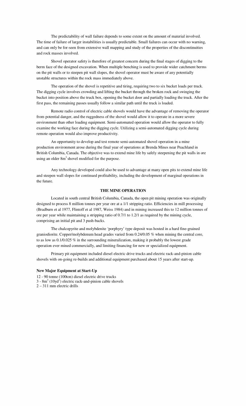
The predictability of wall failure depends to some extent on the amount of material involved.
The time of failure of larger instabilities is usually predictable. Small failures can occur with no warning,
and can only be for-seen from extensive wall mapping and study of the properties of the discontinuities
and rock masses involved.
Shovel operator safety is therefore of greatest concern during the final stages of digging to the
berm face of the designed excavation. When multiple benching is used to provide wider catchment berms
on the pit walls or to steepen pit wall slopes, the shovel operator must be aware of any potentially
unstable structures within the rock mass immediately above.
The operation of the shovel is repetitive and tiring, requiring two to six bucket loads per truck.
The digging cycle involves crowding and lifting the bucket through the broken rock and swinging the
bucket into position above the truck box, opening the bucket door and partially loading the truck. After the
first pass, the remaining passes usually follow a similar path until the truck is loaded.
Remote radio control of electric cable shovels would have the advantage of removing the operator
from potential danger, and the ruggedness of the shovel would allow it to operate in a more severe
environment than other loading equipment. Semi-automated operation would allow the operator to fully
examine the working face during the digging cycle. Utilizing a semi-automated digging cycle during
remote operation would also improve productivity.
An opportunity to develop and test remote semi-automated shovel operation in a mine
production environment arose during the final year of operations at Brenda Mines near Peachland in
British Columbia, Canada. The objective was to extend mine life by safely steepening the pit walls in ore
using an older 8m3
shovel modified for the purpose.
Any technology developed could also be used to advantage at many open pits to extend mine life
and steepen wall slopes for continued profitability, including the development of marginal operations in
the future.
THE MINE OPERATION
Located in south central British Columbia, Canada, the open pit mining operation was originally
designed to process 8 million tonnes per year ore at a 1/1 stripping ratio. Efficiencies in mill processing
(Bradburn et al 1977, Flintoff et al 1987, Weiss 1984) and in mining increased this to 12 million tonnes of
ore per year while maintaining a stripping ratio of 0.7/1 to 1.2/1 as required by the mining cycle,
comprising an initial pit and 3 push-backs.
The chalcopyrite and molybdenite ‘porphyry’ type deposit was hosted in a hard fine-grained
graniodiorite. Copper/molybdenum head grades varied from 0.24/0.05 % when mining the central core,
to as low as 0.1/0.025 % in the surrounding mineralization, making it probably the lowest grade
operation ever mined commercially, and limiting financing for new or specialized equipment.
Primary pit equipment included diesel electric drive trucks and electric rack-and-pinion cable
shovels with on-going re-builds and additional equipment purchased about 15 years after start-up.
New Major Equipment at Start-Up
12 - 90 tonne (100ton) diesel electric drive trucks 3 - 8m3 (10yd3) electric rack-and-pinion cable shovels 2 – 311 mm electric drills
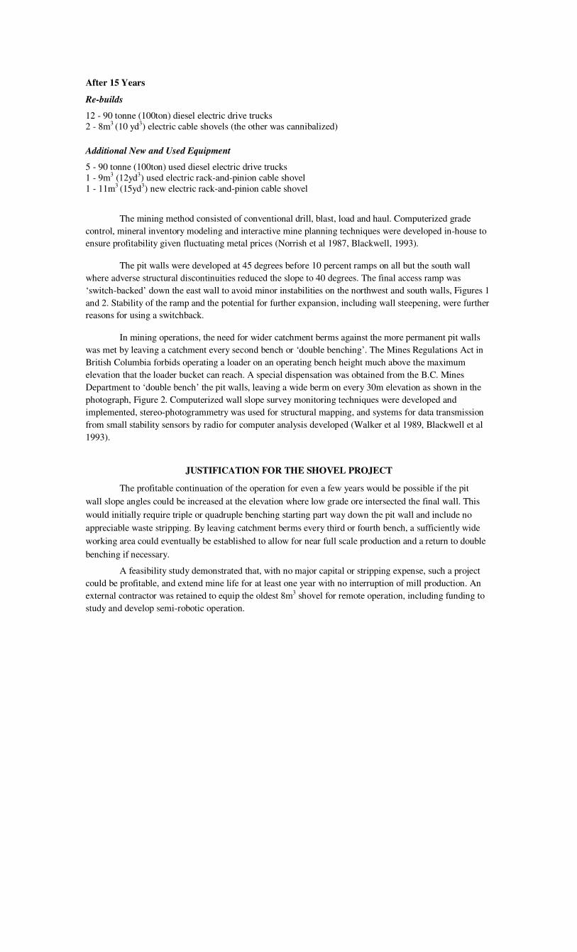
After 15 Years
Re-builds
12 - 90 tonne (100ton) diesel electric drive trucks 2 - 8m3 (10 yd3) electric cable shovels (the other was cannibalized)
Additional New and Used Equipment
5 - 90 tonne (100ton) used diesel electric drive trucks 1 - 9m3 (12yd3) used electric rack-and-pinion cable shovel 1 - 11m3
(15yd3) new electric rack-and-pinion cable shovel
The mining method consisted of conventional drill, blast, load and haul. Computerized grade
control, mineral inventory modeling and interactive mine planning techniques were developed in-house to
ensure profitability given fluctuating metal prices (Norrish et al 1987, Blackwell, 1993).
The pit walls were developed at 45 degrees before 10 percent ramps on all but the south wall
where adverse structural discontinuities reduced the slope to 40 degrees. The final access ramp was
‘switch-backed’ down the east wall to avoid minor instabilities on the northwest and south walls, Figures 1
and 2. Stability of the ramp and the potential for further expansion, including wall steepening, were further
reasons for using a switchback.
In mining operations, the need for wider catchment berms against the more permanent pit walls
was met by leaving a catchment every second bench or ‘double benching’. The Mines Regulations Act in
British Columbia forbids operating a loader on an operating bench height much above the maximum
elevation that the loader bucket can reach. A special dispensation was obtained from the B.C. Mines
Department to ‘double bench’ the pit walls, leaving a wide berm on every 30m elevation as shown in the
photograph, Figure 2. Computerized wall slope survey monitoring techniques were developed and
implemented, stereo-photogrammetry was used for structural mapping, and systems for data transmission
from small stability sensors by radio for computer analysis developed (Walker et al 1989, Blackwell et al
1993).
JUSTIFICATION FOR THE SHOVEL PROJECT
The profitable continuation of the operation for even a few years would be possible if the pit
wall slope angles could be increased at the elevation where low grade ore intersected the final wall. This
would initially require triple or quadruple benching starting part way down the pit wall and include no
appreciable waste stripping. By leaving catchment berms every third or fourth bench, a sufficiently wide
working area could eventually be established to allow for near full scale production and a return to double
benching if necessary.
A feasibility study demonstrated that, with no major capital or stripping expense, such a project
could be profitable, and extend mine life for at least one year with no interruption of mill production. An
external contractor was retained to equip the oldest 8m3 shovel for remote operation, including funding to
study and develop semi-robotic operation.

Figure 1. Photograph of the main haul road switchback on the east side of the pit looking south.
The switchback allows drill access to the top of the first double bench (in this case expanding
south) and eventual mining and extraction of the quadruple bench from a temporary ramp down
on the left of the switchback moving to the right. Bottom centre/right the continuation of the
switchback to the deep pit can be seen

The steepening proposal required:
• Development of a small scale mining method using the modified shovel to mine three of the
present double bench elevations to make two quadruple benches, allowing large scale mining to
proceed.
• Adoption of safe mining methods using the remote control of equipment where necessary in
conjunction with advanced wall control and monitoring techniques already developed.
• A mining plan allowing milling operations to continue uninterrupted (from stockpiles) while
producing ore grades and generating revenues well in excess of any extra costs incurred.
Figure 2. Photograph looking west showing the extra berm width produced by ‘double benching’.
A few small wedges cut off access. The drill must retreat back from these, and drill ramps must be
rebuilt to allow mining to continue. The deep pit is in the bottom left
The later development of semi-remote control systems for maintenance, equipment recovery,
dozers, large drills, large haul trucks and explosive loading were planned but implementation delayed until
the shovel, the essential piece of equipment, had been successfully converted to remote control
Wall steepening would start in the north east of the pit, working from the top switchback of the
final ramp as shown in the photograph, Figure 1, mining the 1465 and 1450m bench floor elevations. The
catchment berm at the 1480m double bench would be used for drill access after being cleaned with a dozer.
The 1510m double bench berm would also be cleaned to provide catchment and check stability.
The two benches (1465 & 1450) would be drilled and blasted in one pass, including production and wall
control blasting and cleaning (Blackwell et al 1982). If it were impractical for the large production drills to
incline their masts and provide the means of placing a suitable toe load at the base of the double bench as
shown in Figure 3, a small drill capable of inclined drilling would have to be rented or purchased.
.
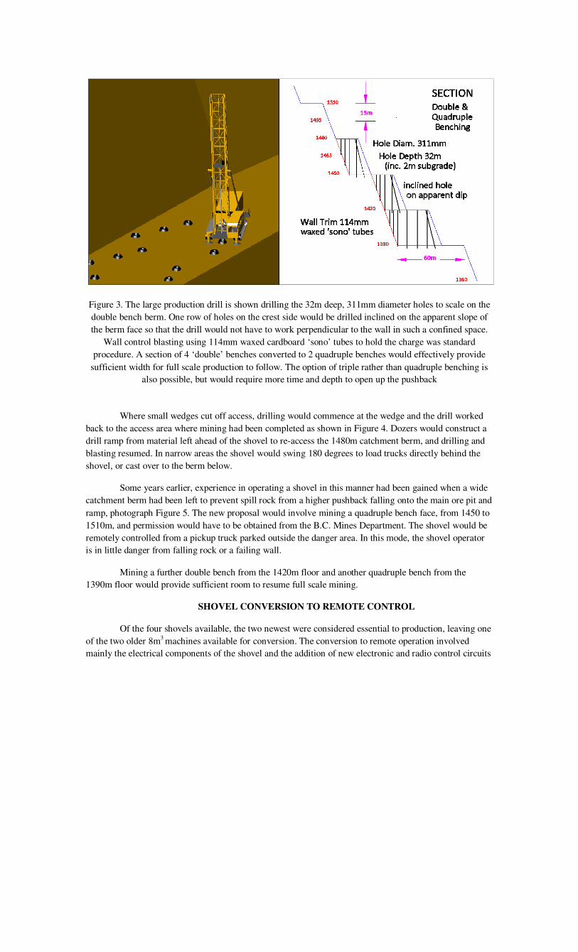
Figure 3. The large production drill is shown drilling the 32m deep, 311mm diameter holes to scale on the
double bench berm. One row of holes on the crest side would be drilled inclined on the apparent slope of
the berm face so that the drill would not have to work perpendicular to the wall in such a confined space.
Wall control blasting using 114mm waxed cardboard ‘sono’ tubes to hold the charge was standard
procedure. A section of 4 ‘double’ benches converted to 2 quadruple benches would effectively provide
sufficient width for full scale production to follow. The option of triple rather than quadruple benching is
also possible, but would require more time and depth to open up the pushback
Where small wedges cut off access, drilling would commence at the wedge and the drill worked
back to the access area where mining had been completed as shown in Figure 4. Dozers would construct a
drill ramp from material left ahead of the shovel to re-access the 1480m catchment berm, and drilling and
blasting resumed. In narrow areas the shovel would swing 180 degrees to load trucks directly behind the
shovel, or cast over to the berm below.
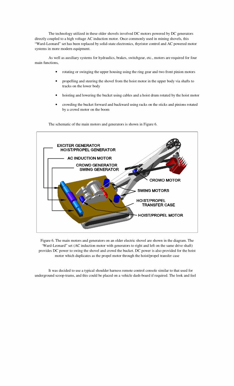
Some years earlier, experience in operating a shovel in this manner had been gained when a wide
catchment berm had been left to prevent spill rock from a higher pushback falling onto the main ore pit and
ramp, photograph Figure 5. The new proposal would involve mining a quadruple bench face, from 1450 to
1510m, and permission would have to be obtained from the B.C. Mines Department. The shovel would be
remotely controlled from a pickup truck parked outside the danger area. In this mode, the shovel operator
is in little danger from falling rock or a failing wall.
Mining a further double bench from the 1420m floor and another quadruple bench from the
1390m floor would provide sufficient room to resume full scale mining.
SHOVEL CONVERSION TO REMOTE CONTROL
Of the four shovels available, the two newest were considered essential to production, leaving one
of the two older 8m3
machines available for conversion. The conversion to remote operation involved
mainly the electrical components of the shovel and the addition of new electronic and radio control circuits
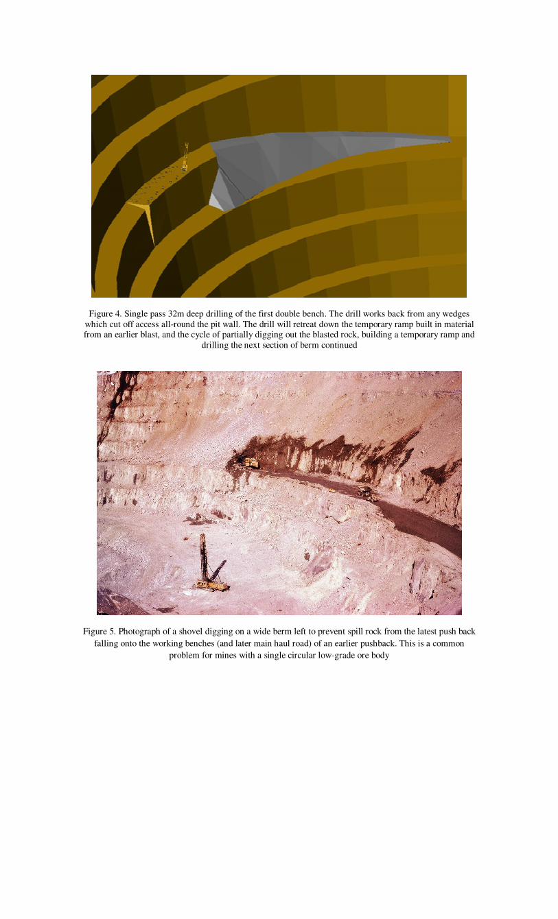
Figure 4. Single pass 32m deep drilling of the first double bench. The drill works back from any wedges
which cut off access all-round the pit wall. The drill will retreat down the temporary ramp built in material from an earlier blast, and the cycle of partially digging out the blasted rock, building a temporary ramp and
drilling the next section of berm continued
Figure 5. Photograph of a shovel digging on a wide berm left to prevent spill rock from the latest push back
falling onto the working benches (and later main haul road) of an earlier pushback. This is a common
problem for mines with a single circular low-grade ore body
The technology utilized in these older shovels involved DC motors powered by DC generators
directly coupled to a high voltage AC induction motor. Once commonly used in mining shovels, this
“Ward-Leonard” set has been replaced by solid-state electronics, thyristor control and AC powered motor
systems in more modern equipment.
As well as auxiliary systems for hydraulics, brakes, switchgear, etc., motors are required for four
main functions,
• rotating or swinging the upper housing using the ring gear and two front pinion motors
• propelling and steering the shovel from the hoist motor in the upper body via shafts to
tracks on the lower body
• hoisting and lowering the bucket using cables and a hoist drum rotated by the hoist motor
• crowding the bucket forward and backward using racks on the sticks and pinions rotated
by a crowd motor on the boom
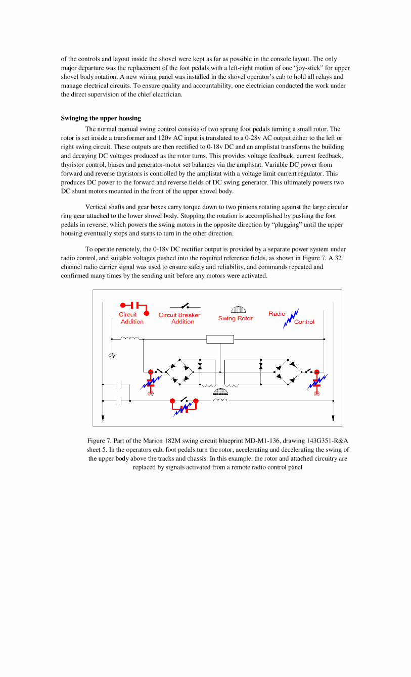
The schematic of the main motors and generators is shown in Figure 6.
Figure 6. The main motors and generators on an older electric shovel are shown in the diagram. The
‘Ward-Leonard” set (AC induction motor with generators to right and left on the same drive shaft)
provides DC power to swing the shovel and crowd the bucket. DC power is also provided for the hoist
motor which duplicates as the propel motor through the hoist/propel transfer case
It was decided to use a typical shoulder harness remote control console similar to that used for
underground scoop-trams, and this could be placed on a vehicle dash-board if required. The look and feel
of the controls and layout inside the shovel were kept as far as possible in the console layout. The only
major departure was the replacement of the foot pedals with a left-right motion of one “joy-stick” for upper
shovel body rotation. A new wiring panel was installed in the shovel operator’s cab to hold all relays and
manage electrical circuits. To ensure quality and accountability, one electrician conducted the work under
the direct supervision of the chief electrician.
Swinging the upper housing
The normal manual swing control consists of two sprung foot pedals turning a small rotor. The
rotor is set inside a transformer and 120v AC input is translated to a 0-28v AC output either to the left or
right swing circuit. These outputs are then rectified to 0-18v DC and an amplistat transforms the building
and decaying DC voltages produced as the rotor turns. This provides voltage feedback, current feedback,
thyristor control, biases and generator-motor set balances via the amplistat. Variable DC power from
forward and reverse thyristors is controlled by the amplistat with a voltage limit current regulator. This
produces DC power to the forward and reverse fields of DC swing generator. This ultimately powers two
DC shunt motors mounted in the front of the upper shovel body.
Vertical shafts and gear boxes carry torque down to two pinions rotating against the large circular
ring gear attached to the lower shovel body. Stopping the rotation is accomplished by pushing the foot
pedals in reverse, which powers the swing motors in the opposite direction by “plugging” until the upper
housing eventually stops and starts to turn in the other direction.
To operate remotely, the 0-18v DC rectifier output is provided by a separate power system under
radio control, and suitable voltages pushed into the required reference fields, as shown in Figure 7. A 32
channel radio carrier signal was used to ensure safety and reliability, and commands repeated and
confirmed many times by the sending unit before any motors were activated.
Figure 7. Part of the Marion 182M swing circuit blueprint MD-M1-136, drawing 143G351-R&A
sheet 5. In the operators cab, foot pedals turn the rotor, accelerating and decelerating the swing of
the upper body above the tracks and chassis. In this example, the rotor and attached circuitry are
replaced by signals activated from a remote radio control panel

Propelling the shovel
The 8m3
shovels available used the bucket hoist motor to propel the shovel. By positioning the
bucket well above the ground and locking the hoist brake, activating the transfer case would provide torque
to a center shaft in the centre of the upper body. Further gears and shafts carry torque down to the two
tracks, which are individually engaged to steer the shovel using track dogs. All the hydraulic systems
involved in the process were controlled remotely by radio.
Normally the operator feels and hears the gears engage and disengage by repeated slow backward
and forward changes of direction, but this was not possible when using remote control. To compensate, a
series of large lights were mounted above the cab to indicate to the distant operator which functions were
applied. Indicator lights on the remote console later augmented these lights.
Loading the bucket
Hoisting and crowding the bucket requires more power and a slower response than the swing
system, and current limit voltage regulators are used. The radio control manages power to the hoist and
crowd motors, including braking, etc., in a manner somewhat similar to the swing control.
Auxiliary functions
Other essential functions included the bucket door trip, whistle, compressed air solenoids for
brakes and greasing, and various safety over-rides were also adapted for radio control.
REMOTE SHOVEL OPERATION
Shovel operators and oilers (trainees) were made familiar with remote control when the converted
shovel was located at the low grade stockpile. Initially the operator walked around the shovel loading a
bucket on one side and dumping the load on the other to gain confidence. The preferred position to run the
shovel was behind and to the left or right. Operation on top of the dump in front of the shovel was tried but
abandoned as this completely disoriented the operator.
For the initial loads, the truck driver exited the truck until loading was completed. Judging the
position of the shovel bucket over the truck box proved to be extremely difficult. Problems included hitting
the rear of the truck box with the bucket, dumping the bucket load over the front bull-board of the truck, or
over either side. Only when the shovel operator gained sufficient experience, usually several hours, was the
truck driver allowed to remain in the truck during loading, and typical operations are shown in the
photograph Figure 8.
Although television cameras were not installed, they were included in the original specifications.
From the experience gained, a wide angle camera following the bucket in the same manner as the operator
watches the bucket would be essential in reducing spill rock around the shovel, a major factor in tire
breakage. Other cameras would be used to watch the digging face, and areas all-round the shovel.
The conversion of the shovel to remote control was successfully implemented, and production
rates only marginally reduced from those achieved in normal operation.
Methods of operation while working under double bench sized instabilities had been developed.
In these situations the shovel dug as much as possible, loading trucks with single backup when appropriate,
until the wall material became obviously unstable. The shovel would then leave the immediate area and
mine other material until the wall had raveled and eventually stabilized before returning. The procedure for

the shovel was to position the tracks perpendicular to the digging face, with the power cable aligned to
always be between the tracks when the shovel reversed.
Figure 8. Photograph showing the operation of the shovel by remote control. The operator stands behind
and to the left of the shovel when loading on the left hand side. Note the difficulty in judging where the
shovel bucket is with respect to the truck box. The truck driver will remain in the truck only after the
shovel operator has gained confidence and is unlikely to hit the truck box with the shovel bucket
In normal production, double backup loading was preferred and facilitated using portable cable
arches to allow trucks to access the shovel on the cable side. Using lugs installed on the top front of the
truck box bull-board, these arches could be picked up by any haul truck. When digging instabilities, one
truck was assigned to have the cable arch already lifted. With the truck facing the instability and ready to
back away with the shovel, the truck driver ensured the cable remained between the shovel tracks.
The photograph Figure 9 shows the method in use against a double bench where rock is raveling
away from a slip plane behind and parallel to the pit wall.
SEMI-ROBOTIC SHOVEL CONTROL
The digging cycle of the shovel is repetitive and computer control of the task is therefore
advantageous. By installing a computer in the shovel, and having the shovel operator fill and dump the
initial bucket load or first “pass”, the computer would have the bucket follow the same path until loading
was complete. The hoist/crowd and swing paths are shown in Figure 10. The shovel operator would have
the ability to “nudge’ the bucket a few meters during the cycle to more efficiently fill the bucket and
distribute the load in the truck box.

Figure 9. Photograph of the procedure for digging an unstable berm face. The shovel operator
works from the truck holding the cable arch, ensuring that the shovel tracks are perpendicular to
the wall, and that the shovel can reverse quickly without damaging its electrical cable. The truck
being loaded is signaled to leave quickly if the instability becomes active, and the crew move to
the area in the foreground, digging conventionally from this muck pile until the wall behind
becomes more stable. The process is repeated until the unstable berm face is safely removed

Figure 10. The semi-robotic digging process is shown in the diagram, and the first pass requires some skill
to empty the bucket squarely into the truck box. The path digging through the muck pile through swinging
and dumping (boom and bucket only) is shown. This path and the return to dig again is stored in an on-
board computer. The computer then repeats the process and the operator can improve the bucket fill factor
and distribute the load evenly in the truck box by ‘nudging’ the bucket with the joystick controls
In order to semi-robotically operate the shovel, the three dimensional position of the bucket has to
be known at all times. Sensors consisting of pairs of metal detectors monitored the toothed gears
transferring torque to the swing, hoist and crowd. Two calibrated sensors close together and can detect the
direction of rotation and count the number of passing teeth to locate the position of the gear. Using the
swing system as an example, sensors were attached to a frame on the upper body hanging down beside the
large ring gear on the lower body, as shown in the photograph Figure 11. These sensors are large because
wear on the centre journal of the older shovel caused the upper body to sway many centimeters and move
up and down at the ring gear. Modifications were required as the gear was not perfectly round, and had a
few teeth missing.
The hoist sensor was mounted on the hoist flywheel gear cover and was the simplest to install and
monitor. The crowd system sensor was the most complex to install, as a series of intermediate shafts and
gears were hidden inside the boom. The final gear next to the pinion, despite being always liberally
greased, was used to locate the crowd. Grease itself did not affect the sensors, but any grease build was
regularly removed.
The study demonstrated that computer assisted control was possible, and would be of major
benefit in reducing operator strain, especially when operating a shovel remotely, or when the truck box was
small in comparison to the shovel bucket. The work also indicated that semi-automated loading was
possible by using cameras and fully automated by using pattern recognition technologies to determine the
location of the muck-pile and truck box.

Figure 11 Photograph of the swing sensors installed to monitor the position of the upper body in relation to
the tracks, and also swing direction and speed. Modifications were required because on older machines the
ring gear is not perfectly circular and may have teeth missing. ‘Play’ in the centre shaft is such that the
sensors also move up and down against the ring teeth
PROJECT COST AND DURATION OF CONVERSION
The contractor costs incurred totaled $150,000 in 2004 Canadian Dollars. On site costs, including some
parts and electrical labour and supervision added a further $50,000. The electrical modifications on the
shovel were completed in one month, and the contractor spent a further month on testing, modifications
and computer control.
MINE CLOSURE
Just before the first bench was to be prepared for drilling followed by mining with the modified
shovel, a major instability developed involving the west wall of the pit. The velocity of wall movement
continued to increase, and the pit was abandoned a few months ahead of schedule. Mining of a small
pushback and stockpile material continued to allow an orderly closure.
The pit west wall did fail, and in a predictable manner as shown by the stability monitoring. It
would have been possible to operate a remote controlled shovel safely and advantageously in such a
situation, and the project was the last advance in mining research made by the company. Originally
developed as a 12 year mine operation processing 24,000 short tons per day, the mine closed in 1990 after
some 22 years, raising production to 33,000 metric tonnes per day. Over the life of the mine, a 50%
increase in mill throughput and an 80% increase in mine life was achieved.

CONCLUSIONS AND RECOMMENDATIONS
The equipment operators had no difficulties in operating the shovel remotely, and accepted the
concept of remote control, each developing their own preferred techniques for the task. The cost of
conversion was minimal, and the work was completed in a one month period without any shutdown of the
shovel exceeding 8 hours (normal scheduled maintenance) or so at a time. The untimely mine closure
prevented the full exploitation of semi-robotic control, but valuable lessons were learned.
The concept of remote shovel operation was proven, and could be used in any situation where the
safety of equipment operators is of concern.
It was also demonstrated that the life of open pit mines could be extended at minimal cost by
starting a push back in ore part way down the pit wall.
Mining literature over the past several years gives examples of the effect of wall slopes on project
viability. Providing the change in net present value per degree of change in wall slope is difficult given the
options for quickly re-starting mining (Coates et al, 1977, Singh, 1986). By adopting remote and semi-
robotic operation of equipment (especially loaders) at the conceptual stage, many marginal open pit
operations might become significantly more profitable.
ACKNOWLEDGEMENTS
The contribution and support of the employees and management of Brenda Mines, and its
majority shareholder, Noranda, is gratefully acknowledged. Over the life of the operation, all employees
proactively embraced change in order to ensure the profitability of mining such a low grade ore body.
The work of the contractor, Black Box Controls, is gratefully acknowledged.
Without the contribution of the contracting, electrical, mechanical and mining personnel involved,
the remote shovel project could not have succeeded.
J. Bertrand, M. Black, E. Broxx, B. Doerksen, G.R. Harris, I. Monahan, M. Morgan, M. Oshkoff,
R. Patey, and W. Scribner are just a few of the people who provided their skills and support.
REFERENCES
Bradburn, R.G., B.C. Flintoff and R.A. Walker, (1977), Practical approach to digital control of a
grinding circuit at Brenda Mines Ltd., Trans SMA of AIME, v 266, no2, June 1977, pp. 140-145
Flintoff, B.C., R,G, Bradburn,.and A.I. Mular, (1987), Canadian trends in the control of mineral
processes: a case study at Brenda Mines Ltd. Copper ’87, Vina del Mar, Chile, Nov.1987
Weiss, A. (1984), Worldwide assessment of the most profitable computer applications in the
mineral industry. 18th
APCOM, London, March 1984, (IMM, London, U.K.), pp. 575-581
Norrish, N. and G. Blackwell, (1987), A mine operator’s implementation of geostatistics. CIM
Bull. v 80, no 899, March 1987, pp.103-112
Blackwell, G. (1993), Computerized open pit mine planning. IMM Bull. Trans. A, 71-152, v 102,
May-August 1993, pp. A83-A88

Johnston, T. and G. Blackwell, (1986), Short and long term open pit planning and grade control.
In David, M., R, Froidevaux, and A. Sinclair, eds. Proc symp. Ore reserve estimation, methods, models and
reality, May 1986, (Geol. Div of CIM, Montreal, Canada), pp. 108-129
Blackwell, G. and A. Bonham-Carter, (1993), Remote survey slope monitoring. In Elbrond, J. and
X. Tang, X., eds 24th APCOM, Montreal, November 1993, (CIM, Montreal, Canada), pp. 493-500
Walker, R.A., G. Blackwell, T, Javorsky, anf G. Scheltgen, (1989), Reinforcement and radio
telemetry monitoring of a wedge structure. CIM Bull., v 82, no 931, November 1989, pp. 47-52
Blackwell, G. and P. Calder, (1982), Practical aspects of wall stability at Brenda Mines Ltd. In
Brawner, C.O. ed. Proc. Int. conf. stability in surface mining, Vancouver, August 1982, (SME of AIME,
Littleton, Colorado), pp.573-608
Coates, D.F. et al., (1977), Pit slope manual, chapter 5, design. Canmet report 77-5, Ottawa,
Canada, 1977, 125 pp
Singh, S.P., (1986), Economical and geotechnical aspects of steeper slopes. In Singhal, R.K. ed.
Proc. Int. symp. on geotechnical stability in surface mining, Calgary, November 1986, (Balkema,
Rotterdam), pp. 23-29