REMEDIAL OF SIDE CUTS AND LANDSLIDE LANDSLIDE MITIGATION ... · REMEDIAL OF SIDE CUTS AND LANDSLIDE...
12
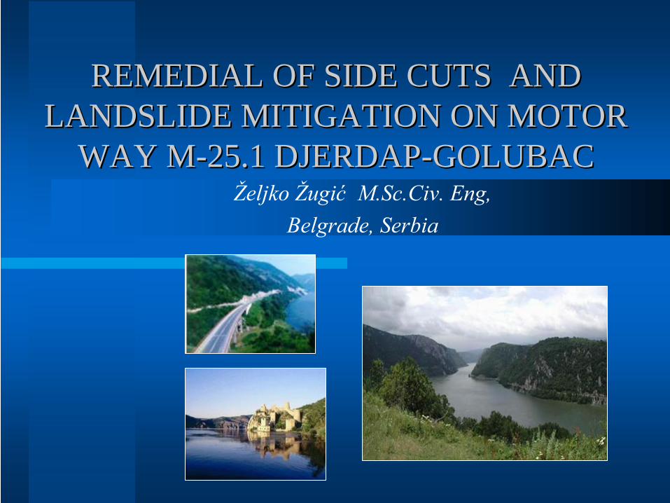
REMEDIAL OF SIDE CUTS AN REMEDIAL OF SIDE CUTS AN D D LANDSLIDE LANDSLIDE MITIGATION ON MOTOR MITIGATION ON MOTOR WAY M WAY M - - 25.1 DJERDAP 25.1 DJERDAP - - GOLUBAC GOLUBAC Željko Žugić M.Sc.Civ. Eng, Belgrade, Serbia
Transcript of REMEDIAL OF SIDE CUTS AND LANDSLIDE LANDSLIDE MITIGATION ... · REMEDIAL OF SIDE CUTS AND LANDSLIDE...
REMEDIAL OF SIDE CUTS ANREMEDIAL OF SIDE CUTS AND D LANDSLIDELANDSLIDE MITIGATION ON MOTOR MITIGATION ON MOTOR
WAY MWAY M--25.1 DJERDAP25.1 DJERDAP--GOLUBACGOLUBACŽeljko Žugić
M.Sc.Civ. Eng,
Belgrade, Serbia
XVIII EYGEC -Zeljko Zugic,Serbia 2
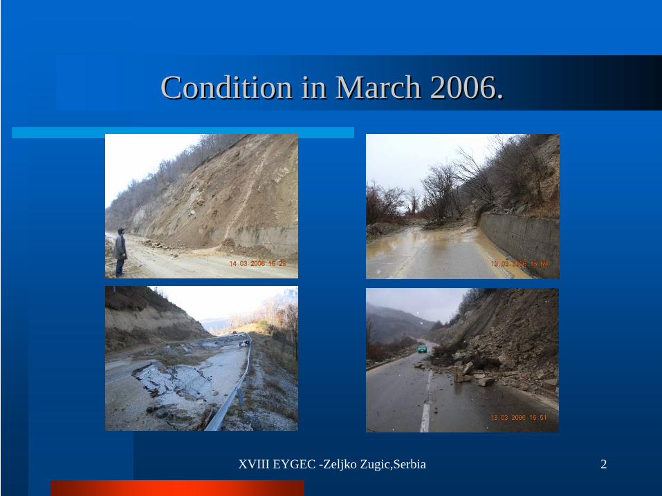
Condition in March 2006Condition in March 2006..
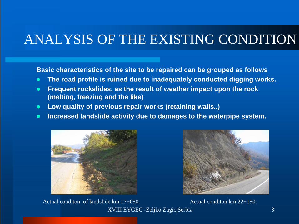
XVIII EYGEC -Zeljko Zugic,Serbia 3Actual conditon of landslide km.17+050. Actual conditon km 22+150.
Basic characteristics of the site to be repaired can be grouped as followsThe road profile is ruined due to inadequately conducted digging works.Frequent rockslides, as the result of weather impact upon the rock (melting, freezing and the like)Low quality of previous repair works (retaining walls..) Increased landslide activity due to damages to the waterpipe system.
ANALYSIS OF THE EXISTING CONDITION
XVIII EYGEC -Zeljko Zugic,Serbia 4
DESGIN SOLUTIONS DESGIN SOLUTIONS To the purpose of selection among design
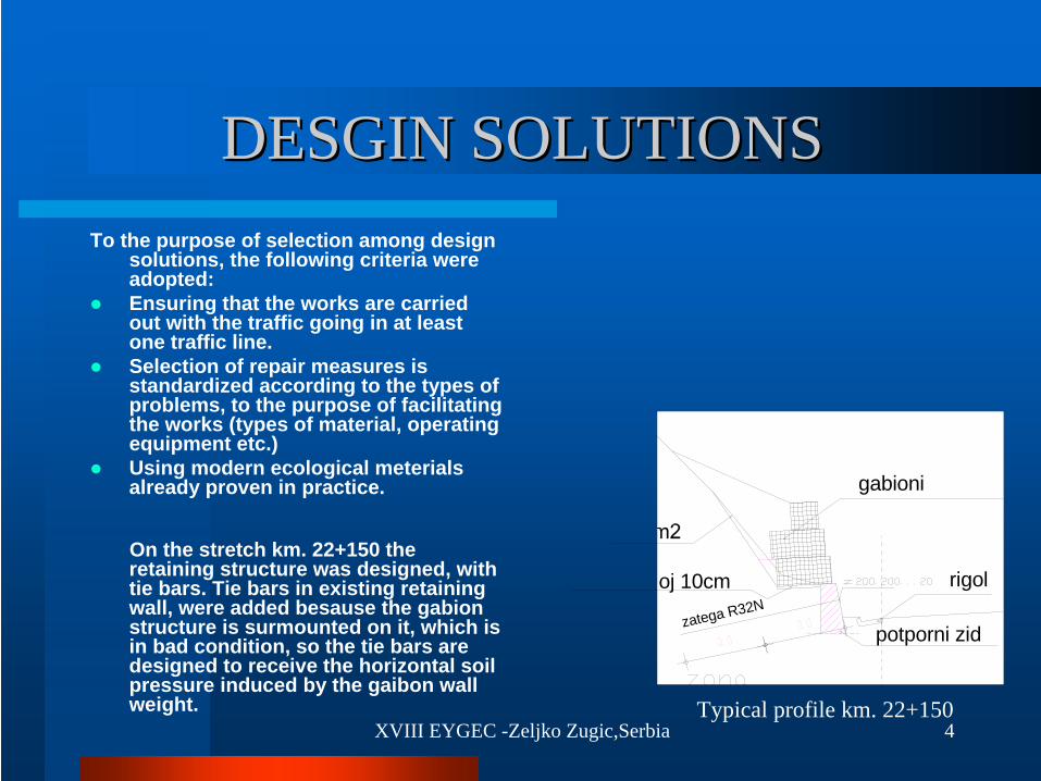
solutions, the following criteria were adopted:Ensuring that the works are carried out with the traffic going in at least one traffic line.Selection of repair measures is standardized according to the types of problems, to the purpose of facilitating the works (types of material, operating equipment etc.)Using modern ecological meterialsalready proven in practice.
On the stretch km. 22+150 the retaining structure was designed, with tie bars. Tie bars in existing retaining wall, were added besause the gabion structure is surmounted on it, which is in bad condition, so the tie bars are designed to receive the horizontal soil pressure induced by the gaibon wall weight.
gabioni
oj 10cm
potporni zid
rigol
zatega R32N
Typical profile km. 22+150
XVIII EYGEC -Zeljko Zugic,Serbia 5
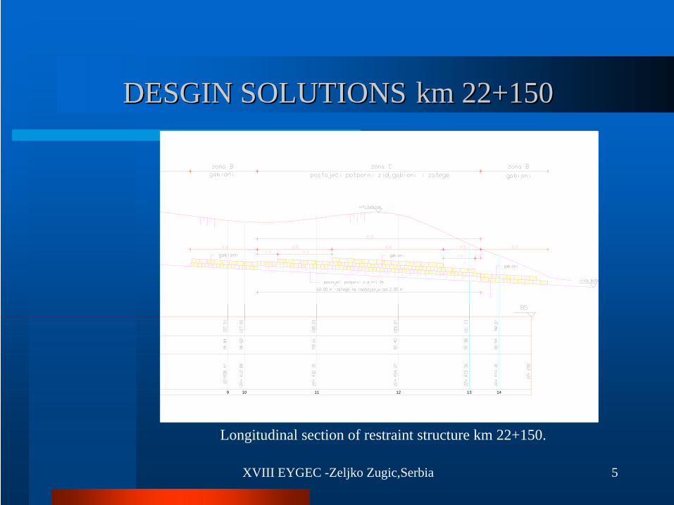
9 10 11 12 13 14
Longitudinal section of restraint structure km 22+150.
DESGIN SOLUTIONSDESGIN SOLUTIONS km 22+150km 22+150

XVIII EYGEC -Zeljko Zugic,Serbia 6
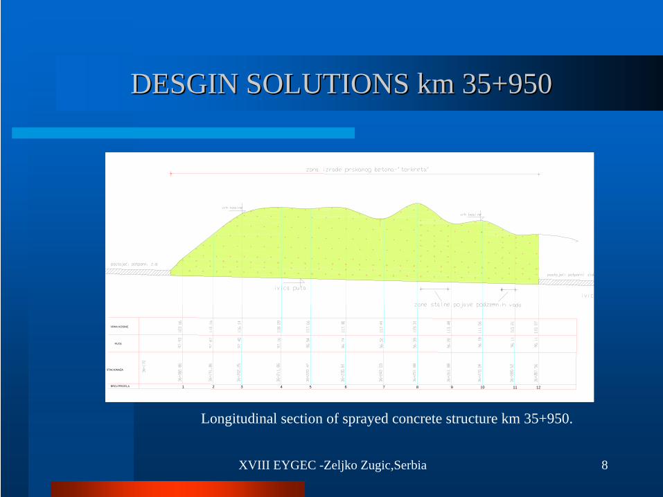
DESGIN SOLUTIONSDESGIN SOLUTIONS km 35+950km 35+950
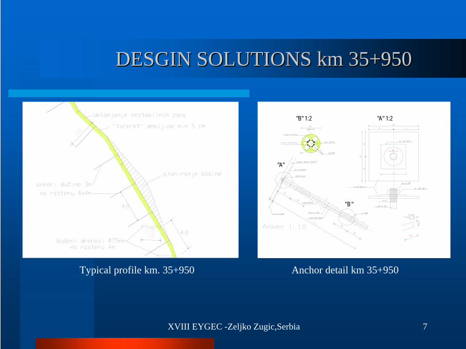
The protection on the stretch km 35+950 with sprayed concrete is as follows:planing the slope: clearing the growth, the unstable perts and flattening rough surfaces,constructing anchores to improve the conection between „torquet“ coating and rock materials as well as fixing the steel mesh to the slope. The anchores are to be put in the 4,00x4,00m. pattern, they are 3,00m in length, which enables their anchoring into the undegraded zone of rock mass. The anchors drill diameter is 75mm., and they were made of ribed steel (25mm).planting a steel grid to the purpose of „reinforced“ sprayed concrete. The grid is made of steel 240/360 steel, 2.7mm in diameter. It is fixed to the slope using the previously built anchores , or using steel „clinching irons“ if necessary.sprayed concrete -«torquet», applied in the minimum 5cm layerover the constructed steel mesh and anchors and drainage drills to eliminate hydrostatic pressure from the slope hinterland. Upon the completion of the sprayed concrete construction, the horizontal drain tiles are planted through the solidified layer and the area behind the „torquet“(rock mass). The drill diameter is 75 mm, the width is 2,00m whereas the inclination amaounts to approximately 2-3 % towards the slope, to the purpose of water evacuation.
XVIII EYGEC -Zeljko Zugic,Serbia 7
"A"
"B "
"B" 1:2 "A" 1:2
Typical profile km. 35+950 Anchor detail km 35+950
DESGIN SOLUTIONSDESGIN SOLUTIONS km 35+950km 35+950
XVIII EYGEC -Zeljko Zugic,Serbia 8
DESGIN SOLUTIONSDESGIN SOLUTIONS km 35+950km 35+950
VRHA KOSINE
PUTA
STACIONAŽA
BROJ PROFILA 1 2 3 4 5 6 7 8 9 10 11 12
Longitudinal section of sprayed concrete structure km 35+950.
XVIII EYGEC -Zeljko Zugic,Serbia 9
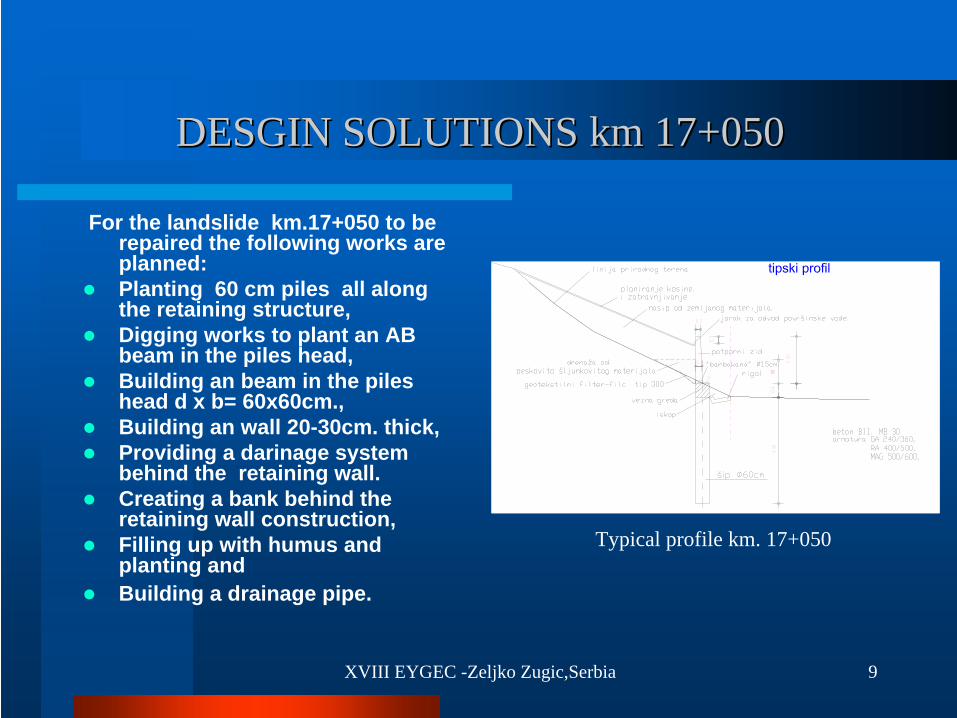
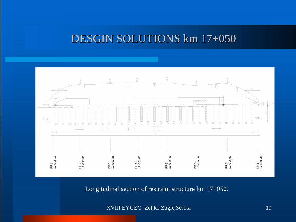
DESGIN SOLUTIONSDESGIN SOLUTIONS km 17+050km 17+050
For the landslide km.17+050 to be repaired the following works are planned:Planting 60 cm piles all along the retaining structure,Digging works to plant an AB beam in the piles head,Building an beam in the piles head d x b= 60x60cm.,Building an wall 20-30cm. thick,Providing a darinage system behind the retaining wall.Creating a bank behind the retaining wall construction,Filling up with humus and planting and Building a drainage pipe.
Typical profile km. 17+050
XVIII EYGEC -Zeljko Zugic,Serbia 10
PR
117
+105
.13
PR
217
+113
.87
PR
317
+122
.88
PR
417
+131
.05
PR
517
+140
.43
PR
617
+149
.24
PR
717
+158
.82
PR
817
+168
.38
I
Longitudinal section of restraint structure km 17+050.
DESGIN SOLUTIONSDESGIN SOLUTIONS km 17+050km 17+050
XVIII EYGEC -Zeljko Zugic,Serbia 11
CONCLUSIONCONCLUSION
Having in mind all the impressions during the completion of this project documentation, a conclusion can be drawn that a good preparation, primarily as regards obtaining valid geodetic and geological elaborates is a necessary precondition in order that a good project be designed. It is in this context that we strees the importance of selecting a constructive solutions, whereas the execution itself (stability calculations and providing technical drawings) make the easier part of the work.

XVIII EYGEC -Zeljko Zugic,Serbia 12
Special thanks to ISSMGE for supporting my presence on
XVIII EYGEC
THANK YOU FOR ATTENTION!