REMEDIAL INVESTIGATION AND FEASIBILITY STUDY FINAL … · remedial investigation and feasibility...
140
REMEDIAL INVESTIGATION AND FEASIBILITY STUDY FINAL WORK PIAN EXTERIOR INDUSTRIAL WASTE DITCH NAVAL REACTORS FACILITY IDAHO FALLS, IDAHO APPENDIX E STANDARD OPERATING PROCEDURES AND SAMPLE DATA SHEETS September 1992 Prepared for Department of Energy Pittsburgh Naval Reactors Idaho Branch Office P. 0. 2469 Idaho Falls, Idaho 83403-2469
Transcript of REMEDIAL INVESTIGATION AND FEASIBILITY STUDY FINAL … · remedial investigation and feasibility...

REMEDIAL INVESTIGATION AND FEASIBILITY STUDY FINAL WORK PIAN
EXTERIOR INDUSTRIAL WASTE DITCH NAVAL REACTORS FACILITY
IDAHO FALLS, IDAHO
APPENDIX E
STANDARD OPERATING PROCEDURES
AND
SAMPLE DATA SHEETS
September 1992
Prepared for Department of Energy
Pittsburgh Naval Reactors Idaho Branch Office
P. 0. 2469 Idaho Falls, Idaho 83403-2469
THIS PAGE WAS INTENTIONALLY LEFT BLANK

LEGEND
BA . DP D:: DV . IO ..I. PT . .
.
.
. .
. . .
. .
.
.
.
.
........... Boring and Auguring
...... Decontamination Procedure n,;,,;,, ..................... YI 1,111 ,y
............... Data Validation
........... Instrument Operation
................ Pump Testing
............. Sample Collection
... Standard Operating Procedure
........... Waste Management

THIS PAGE WAS INTENTIONALLY LEFT BLANK

Appendix E September 1992 Page iii
APPENDIX E
SECTION 1
STANDARDOPERATINGPROCEDURES
TABLE OF CONTENTS
SOP-SC-01 . Collection of Samples Using Sample Data Sheets ............ . .
SOP-SC-02 . Subsurface Soil Sampling with a Split-Spoon Sampler .........
SOP-IO-03 . Digital Data Recording Devices for Groundwater Wells .......... . .
SOP-SC-04 - Measuring Depth to Water in a Monitoring Well .............. .
SOP-SC-05 - Collecting Water Samples From New, Uncased Bore Holes ..... . .
SOP-SC-06 - Collecting Water Samples from the Sewage Lagoon ........... . .
SOP-SC-07 I Purging and Collecting Well Samples Using a Submersible Pumps .
SOP-SC-08 - Purging and Collecting Well Samples Using Bailers ........... . .
SOP-SC-OS - Collecting Water Samples from the IWD .................... . .
SOP-DR-IO . Monitoring Well Development ........................... .
SOP-SC-1 1 - Sieving Samples in Preparation for Analysis ................. . .
SOP-SC-12 . Rinsing Gravel Samples with Nitric Acid .................... . .
SOP-IO-13 . Collecting and Reducing Gravimetric Readings ............... . .
SOP-IO.14 - Collection of Resistivity Data ............................. . .
SOP-DP-15 . Heavy Equipment Decontamination .......................
SOP-DP-16 . Sample Equipment Decontamination ......................
SOP-DP-17 . Drilling Equipment Decontamination ...................... . .
SOP-D%18 . Well and Borehole Abandonment ........................
SOP-SC-19 . Chain-of-Custody Procedure ............................ .
. . . l-l
2-l
. * 3-l
. . . 4-1
. . . 5-l
. . 6-l
. . . 7-1
. . . 8-l
. . 9-1
. 10-l
. . 11-l
. . 12-l
. 13-l
. . 14-1
15-l
16-1
17-1
. 18-1
. 19-1

.. Appendix E September 199. Page iv
SOP-DVQO - Data Validation Procedure . . . . . . . . . . . . . . . . . . . . 20-l
SOP-DR-21 - Monitor Well Drilling . . . . . . . . . . . . . . . . . . . . . . . . . . . 21-1
SOP-BA-22 - Boreholing and Auguring . . . . . . , . . . . . . . , . . . . . . . . . . . . . . . . . 22-1
SOP-PT-23 - Pump Testing . . . . . . . . . . . . . . . . . . . . . . . . . . . . . . . . . . . . . . . . . . 23-1
SOP-WM.24 - Management of Investigation Derived Wastes . . . . . . . . . . . . . . . 24-l
SOP-SC-25 - Filtration of Water Samples . . . . . . . . . . . . . . . . . . . . . . . . . . . . . . 25-1
SOP-IO-26 - Field Measurement of pH . . . . . . . . . . . . . . . . . . . . . . . . . 26-1
SOP-IO-27 - Field Measurement of Specific Conductivity . . . . . . . . . . 27-1
SOP-IO-26 - Field Measurement of Water Temperature . . . . . . . . . . . . . . . . . . . . . . 26-l
SOP-IO-29 - Organic Vapor Meter (OVM) _ . . . . . . . . . . . . . . . . . . . . . . . 29-1

Appendix E September 1992 Page v
.-- -- Ll3l VI-
NRF ENVIRONMENTAL REMEDIATION SAMPLE DATA SHEETS
*l. TOTAL METALS FOR SOLID MATRICES - GRAB .....................
*2. TOTAL METALS FOR LIQUID MATRICES - GRAB .....................
3. TOTAL METALS FOR SOLIDS IN A 55 GALLON DRUM .................
4. TOTAL METALS FOR LIQUIDS IN A 55 GALLON DRUM ................
*5. TCLP METALS SOLID MATRICES . GRAB ..........................
6. TCLP METALS IN SOLID MATRICES IN A 55 GALLON DRUM ............
7. TCLP ORGANICS (Semivolatiles & Volatiles) IN SOLID MATRICES - GRAB ...
6. TCLP ORGANICS (Semivoiatiles & Volatiles) IN SOLID MATRICES IN A 55
GALLONDRUM ............................................
9. TCLP METALS IN LIQUID MATRICES - GRAB ........................
10. TCLP METALS IN LIQUID MATRICES IN A 55 GALLON DRUM ...........
*I 1. TCLP SEMIVOLATILE IN LIQUID MATRICES . GRAB ...................
12. TCLP SEMIVOLATILES LIQUID MATRICES IN A 55 GALLQN DRUM .......
*13. TCLP VOIATILES IN LIQUID MATRICES - GRAB .....................
.... -- - ... - .. --. ... “14. TCLP VOLATILES IN LIQUILI MATHIC;tS IN A 55 LiALLUN UHUM .........
*15. SEMIVOV\TILES IN SOLID MATRICES - GRAB .................. : ....
i6. SE‘hii\iQiJ+TiLES iti SOLiD iviATRiCES ii< A 55 GAiiQii DRUivi ...........
“17. SEMIVOIATILES IN LIQUID MATRICES - GRAB ......................
19. OIL AND GREASE IN SOLID MATRICES . GRAB ......................
. SDS-1
. SDS-2
. SDS-3
. SDS-4
. SDS-5
SDS-6
. SDS-7
. SDS-8
. SDS-9
. SDS-10
. SDS-1 1
SDS-12
. SDS-13
--- . sus-14
. SDS-15
. SDS-i6
. SDS-17
CnE~i* . &I”“- I”
SDS-19
.SD.S-20

Appendix E September 19s. Page v:
21. OIL AND GREASE IN LIQUID MATRICES - GRAB ................
22. OIL AND GREASE IN LIQUID MATRICES IN A 55 GALLON DRUM ....
23. PCBs IN SOLID MATRICES - GRAB ..........................
24. PCBs IN SOLID MATRICES IN A 55 GALLON DRUM ..............
25. PCBs IN LIQUID MATRICES . GRAB .......................... . . . . . . SDS-25
26. PCBs IN LIQUID MATRICES IN A 55 GALLON DRUM .................... SDS-26
. . . . . . :: --s-21
.,.... SDS-22
. . . . . . SDS-23
. . . . . . SDS-24
*27. VOLATILE ORGANICS IN SOLID MATRICES . GRAB ................... SDS-27
28. VOLATILE ORGANICS IN SOLID MATRICES IN A 55 GALLON DRUM ....... SDS-28
*29. VOLATILE ORGANICS IN LIQUID MATRICES - GRAB ................... SDS-29
30. VOLATILE ORGANICS IN LIQUID MATRICES IN A 55 GALLON DRUM ....... SDS-30
31. PESTICIDES/HERBICIDES IN SOLID MATRICES - GRAB ................. SDS-31
32. PESTICIDES/HERBICIDES IN SOLID MATRICES IN A 55 GALLON DRUM ..... SDS-32
33. PESTICIDES/HERBICIDES IN LIQUID MATRICES . GRAB ................. SDS-33
34. PESTICIDES/HERBICIDES IN LIQUID MATRICES IN A 55 GALLON DRUM .... SDS-34
*35. MISCELLANEOUS TESTS SOLID MATRICES . GRAB .................... SDS-35
*36. MISCELLANEOUS TESTS IN SOLID MATRICES IN A 55 GALLON DRUM ..... SDS-36
*37. MISCELLANEOUS TESTS IN LIQUID MATRICES . GRAB ................. SDS-37
38. MISCELLANEOUS TESTS IN LIQUID MATRICES IN A 55 GALLON DRUM ..... SDS-38
39. SOLVENT SCREEN IN SOLID MATRICES - GRAB ....................... SDS-39
40. SOLVENT SCREEN IN SOLID MATRICES IN A 55 GALLON DRUM .......... SDS-40
41. SOLVENPSCREEN IN LIQUID MATRICES . GRAB ...................... SDS-41
42. SOLVENT SCREEN IN LIQUID MATRICES IN A 55 GALLON DRUM .......... SDS-42
^_^ .- 43. TOTAL HALOGENS (OIL) IN LIUUID MATRICES - kiRAB .................. SUS-43

Appendix E September 1992 Page vii
. . T-B., ,._. ^^-..- ,-... . .- ..- ..--. --- -- -.. -.. -- --- 44. IUIAL tlALUbtN3 (UIL) IN LIUUIU MAIHV.23 IN A 53 tiALLUN UHUM . . . . . SUS-44
45. NITRATE AS N IN SOLID MATRICES - GRAB . . . . . . . . . . . . SDS-45
1,-Y LIITnA-rr A* .I 1.1 mn, I_ .,Al-lmrn 1.I 1 r- -1, ,.%.I m-l*.* to. I”, Inni c na IY I,” 3”LIU w,n I “lLC3 I,Y n 35 u-!LLUlY UtlUlYl . . . . . . . . . . . . SDS-48
47. NITRATE AS N IN LIQUID MATRICES - GRAB . . . . . . . . . . . . . . . . . . . . . . SDS47
ALI hllTPI\TC AC hl Ihl I In, lls-7 h”*TPlrCC 1k1 n c= en0 I fir.1 nas 11” One “- YV. I., I IWT, L 17” 1. ,111 LlWUlY l”lrtI r7l”LG II” n JJ “mLI”I” Yr7”l”l . . . . . . . . . . O”.JTQ
*49. TOTAL PETROLEUM HYDROCARBONS (TPH) IN SOLID MATRICES - GRAB . . SDS49
50. TOTAL PETROLE~UM HYDROCARBONS (TPH) !N SOL!D MATR!CE.S !N A 55
GALLON DRUM . . . . . . . . . . . . . . . . . . . . . . . . SDS-50
51. TOTAL PETROLEUM HYDROCARBONS (TPH\ IN LlOlJlD MA?R!CES - GRAS SIX-51 , ., -. _ _ _ L-L -.
52. TOTAL PETROLEUM HYDROCARBONS (T?ii) Iid LiQUiD MATRICES IN A 55
GALLON DRUM . . . . . . . . . . . . . . . . . . . . . . . . . . . . . . . . . . . . . . . . . . . . SDS-52
53. APPENDIX VIII CONSTITUENTS IN SOLID MATRICES - GRAB . . . . . . . . . . . . S&53
54. APPENDIX VIII CONSTITUENTS IN SOLID MATRICES IN A 55 GALLON DRUM SDS-54
55. APPENDIX VIII CONSTITUENTS IN LIQUID MATRICES - GRAB . . . . . . . . . . SDS-55
58. APPENDIX VIII CONSTITUENTS IN LIQUID MATRICES IN A 55 GALLON DRUM SDS-56
57. BTEX IN SOLID MATRICES - GRAB . . . . . . . . . . . . . . . . . . . . . . . . . . . . . . . . SDS-57
58. BTEX IN SOLID MATRICES IN A 55 GALLON DRUM . . . . . . . . . . . . . . . . . . . . . SDS-58
59. BTM IN LIQUID MATRICES - GRAB ................................. SDS-59
80. BTM-IN LIQUID MATRICES IN A 55 GALLON DRUM .................... SDS-60
81. COLIFORM BACTERIA IN LIQUID MATRICES - RESERVED ................ SDS-81
82. TOTAL AND TCLP METALS - RESERVED ............................. SDS-82
63. TCLP METALS AND ORGANICS - RESERVED .......................... SDS-63
84. INDUSTRIAL WASTE DITCH PLANT SAMPLING ........................ SDS-84

Appendix E Septemc?r 195. Page vii;
65. INDUSTRIAL WASTE DITCH ALGAE SAMPLING . . . . . . . . . . . . . . . . . S: ;-65
66. MONTHLY INDUSTRIAL WASTE DITCH WASTEWATER LIMITS ANALYSIS . . . SDS-66
*67. GEOCHEMICAL WATER ANALYSIS; SUITE 1, AS DEFINED IN IWD RI/FS FSP . SDS-67
l 66. GEOCHEMICAL WATER ANALYSIS; SUITE 2 AS DEFINED IN THE IWD RI/FS
FSP.......................................................SDS-66
*69. GEOCHEMICAL WATER ANALYSIS; SUITE 1, AS DEFINED IN IWD RI/FS FSP SDS-69
NOTE: Only those SOPS marked with a * will be used on this project and therefore are the only ones enclosed.
Appendix E August 1992 Page 1-1
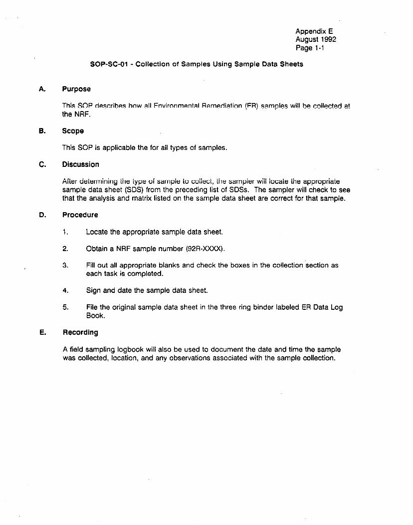
SOP-SC-01 - Collection of Samples Using Sample Data Sheets
A. Purpose
This SOP describes how al! Environmental Remediation (ER) samoles wilt be cottected at the NRF.
B. Scope
This SOP is applicable the for all types of samples.
C. Discussion
.Y-~ ~,~I~~--.-.~~ A,-~ I~ ~~ -.--~~-a~ Lo ~~,a~-. .,-~ ~---~I~ .,*,-~-.~ .a~~ ~~ ~~~ .-. nner oerermrnkq me rype or sampre to correct, me sampler wire locate me appropnare sample data sheet (SDS) from the preceding list of SDSs. The sampler will check to see that the analysis and matrix listed on the sample data sheet are correct for that sample.
0. procedure
1. Locate the appropriate sample data sheet.
2. Obtain a NRF sample number (92R-XXXX).
3. Fill out all appropriate blanks and check the boxes in the collection ‘section as each task is completed.
4. Sign and date the sampie data sheet.
5. File the original sample data sheet in the three ring binder labeled ER Data Log Book.
E. Recording
A field sampling logbook will also be used to document the date and time the sample was collected, location and any observations associated with the sample collection.

THIS PAGE WAS INTENTIONALLY LEFT BLANK

Appendix E August 1992 Page 2-1
SOP-SC-02 - Subsurface Soil Sampling with a Split-Spoon Sampler
A. Purpose
Ttnis SOP describes the procedures for obtaining subsurface soii sampies using a spiii- spoon sampler (also known as a split-barrel sampler).
0. Scope
This SOP is only applicable for obtaining subsurface soil samples with a split-spoon sampler, and then containerizing the soil samples in sample bottles. This SOP also describes the requirements for drilling to the desired sampling depth, obtaining the sample. and sample collection. The equipment, materials, and the data recording requirements are also detailed.
C. Apparatus and Materials
1.
2.
3.
4.
5.
6.
Drilling equipment (as described in the references and specified in the Field Sampling Plan) Sampling drill rods (“A” size rod for depths less than 50 feet, or “N” size rod for depths greater than 50 feet) P-l:* ^^^^^ ^^-^1..- ‘:11^.4 . . ..a. *^-A^..^A AA.,. ^L.?...^ -..A L. ^..I,^ l *^+^i -,.*.. n a..,^ qJ”‘qJ”“l’ Da.IIIpI~I IttLtz” ““llll Ilcn”cjllci” “ll”ci JIlUFIJ a.I,u uaz.nc, Irlall,TID. n L”“”
inch diameter sampler is recommended for unconsolidated clays, silts, sands, and fine gravels; a four inch or larger diameter sampler is recommended for coarse gravels and cobbles, or when larger sample volumes are required for chemical C#!a!ySiS, Drive weight assembly as described in the references and as specified in the Field Sampling Plan. Accessory sampling equipment (i.e., teflon or stainless steel scoops and bowls, sample bottles). Documentation material (NRF Sample Data Sheets, NRF Chain-of-Custody forms, NRF Sample Labels and Seals, and the Field Log Book).
D. Procedures
The procedures for subsurface sampling will be the same as those detailed in the ASTM method D 158664. The procedures for collection of the sample in sample bottles for laboratory analysis are detailed in the Sample Data Sheet(s) for the required analytical ms,h,TA 3-a rnc.ri‘inA in the Cic.lA C2amnlinn Dll” Ctric-+ Annth rnntrnl nrcw.tirac mt I=+ hn ,,,“..,“- ..- YP’“.““” ,,. ..,” , ,“,” ~..,.*P.‘.‘~ , ,...,. v.I.-. ““y... “- . . . . -, P.“-......- . ..--. “.. followed to ensure that the sampler is resting at the desired sample depth. The depth to the sample point horizon shall be measured using the combined lengths of down hole tools and drill rods (the combination of this equipment is known as the drill string) relative to a fixed point above the ground surface. The sample depth is determined by subtracting the length of the drill string above the ground from the total drill string length.

Appendix E August 1992 Page 2-2
insufficient Sample Collection
F. Filling of Sample Bottles \
G. Data Recording
The drilling information required to be recorded in the field log is detailed in the ASTM method D 158684. If the four inch or larger diameter split-spoon sampler is used, the blow count will not be required, since this information will not be useful in determining soil properties for this type of split-spoon sampler.
H. References
ASTM Method D 158664, “Standard Method for Penetration Test and Split-Barrel Sampling of Soils”
U. S. Geological Survey (USGS), “Techniques of Water-Resource Investigations of the USGS: Application of Drilling, Coring and Sampling Techniques to Test Holes and Wells”

Appendix E August 1992 Page 3-1
SOP-IO-03 - Digital Data Recording Devices for Groundwater Wells
A.
B.
C.
Purpose
This SOP describes the materials needed and the steps required to collect water level data from groundwater wells using the lnsitu Kermit IOOOC data recorder.
Scope
This SOP describes the procedures for operating a data recorder.
Apparatus and Materials
1. 2. 3. 4. 5. 6. 7. 8.
lnsitu Hermit SE 1OOOC Data Logger 150’ to 400’ cable reel! with PXD-260 transducer 15’ jumper cable RS-232 interface cable lnsitu data transfer software 366 DX or better computer Duct tape lnsitu Hermit 1OOOC Operator’s Manual
D. Procedure
1. Turn on the Hermit IOOOC by touching any’key.
2. Simultaneously press ENTER and DATA and choose menu name TYPE. Select the tvne of lnnninn as ‘Yeve!“. .,r. -~ .___~ -_ se!ec! tha rest nf tha inntit narametarc ~wvlar tha .._ .__. _. . .._ ...r-. p _.I..._._._ _..__. . .._ DATA menu to fit the specific circumstance. Refer to page 51 of the Operator’s Manual for more information.
3.
4.
Simultaneously press ENTER and XD. Program the transducer parameters of scale factor, offset, and linearity. Remember to set to zero any parameters not specified.
Program the transducer warmup delay. Set it to 50 mSEC if not specified otiietwise.
5. Select the display mode: En:Sur
62 I n!l,Pr ,hP tmncr-4, IPa, hanelth ttT.3 \A,l+a” CI IdlCP I lntil it .alrhne the knttnm n‘ tLl.2 “. k”.TV! .!I” ..UII”““““. ““II~“.II .I,” . . . . ..I. .?“I lUII “I 1.11 II IU.A”I ,.,.z .I II ““LL”,, I v, ,I I.4 bore casing. Raise the transducer off the bottom about 1 foot. Secure the transducer in place by forming a small loop in the transducer cable. Secure the loop using duct tape. Allow the transducer and cable to hang freely in the tiell by being supported by the taped loop.

7.
0.
9.
10.
11.
12.
Appendix E August 1992 Page 3-2
Press the XD key to check the transducer operation. The reading shown on the display is ihe iiCdiSdiXc3i head. Ensure inai the range of ihe iransducar is not exceeded (for the PXD-260 transducer, this is 23.1 feet).
Measure the level of the water in the well using SOP-SC-04. Convert this level to elevation above sea level by sub?rac?fng r! from ttlfa InazaEl ,,a4 .al,Mr~+inn rr‘ t5.a tn.. . . . . . ..-..-I.“” “I”.U.I”I, “I LIII WI. of the casing.
Input the reference level with the transducer set and connected to the instrument. The reference level is the value calculated in Step 8.
Begin data collection as per instructions on page 63 of the Operator’s Manual.
Stop data collection as per instructions on page 67 of the Operator’s Manual.
Download stored data as per instructions on page 81 of the Operator’s Manual and pages 3 through 9 of the Data Transfer User’s Guide.
E. References
Insitu, Inc., Hermit 1OOOC Operator’s Manual Insitu, Inc., Pressure Transducer, Model PXD-260 Operator’s Manual Insitu, Inc., Data Transfer User’s Guide
F. Documentation
A copy of all measurements are kept in the Environmental Remediation File System, secaioii 39,

Appendix E August 1992 Page 4-1
SOP-SC-04 - Measuring Depth to Water In a Monitoring Well
A. Purpose
This SOP describes the procedure for measuring the depth to water in a monitoring well.
B. Scope
This SOP describes in detail all the requirements for measuring depth to water in all monitoring wells. It also identifies the precautions to be used to prevent well water contamination.
C. Apparatus and Materials
i. Eiectric iapejweii indicator unit 2. 9 volt battery 3. Ruler - at least 3” long - graduated in l/8 of an inch 4. Deionized water (1 -liter squeeze bottle) 5. Clm,cx lrnttnn nr n*rlnn\ “I”““.J \““..“‘I “I l’,,““,
D. Precautions
1. Steps must be taken to prevent contamination of well water from surface water and particulate matter. The indicator probe and electric tape that will be placed into the well shall be rinsed with deionized water prior to use in each well.
2. When handling the indicator probe and electric tape, ensure your gloves are clean. Change gloves as necessary.
3. The electric tape and probe must not be allowed to contact the ground. Place on clean plastic as necessary.
E. Procedure
1. Perform a battery check on the electric tape/well indicator unit.
2. Place a level stick or rule on top of open metal casing.
3. Rinse the indicator probe with deionized water and shake off excess moisture.
4. Slowly lower the electric tape and probe into the middle of the well casing until the detector beeps. If the approximate depth is known, the tape may be lowered rapidly until within a few feet of the approximate level, and then lowered slowly for an accurate detection of the surface of the well water.
5. Note the reading on the electric tape at the level stick or rule. Read the scale to the nearest l/iOOth of a foot and record.

Appendix E August 1992 Page 4-2
F.
6. Thoroughly rinse the probe with deionized water.
Documentation
G.
Record the results of the measurement.
References
Fisher M-Scope, Model U

A.
B.
c.
D.
Appendix E August 1992 Page 5-1
SOP-SC-05 - Collecting Water Samples From New, Uncased Bore Holes
Purpose
This SOP describes the materials needed and steps required to collect water samples from newly drilled wells where perched water is encountered.
Scope
This SOP defines the procedures necessary to collect samples from uncased, newly drilled bore noies.
Apparatus and Materials.
1. 9 c -al,m.. r+3in,arr Ftnnl h,,rbo,r L ” y”““‘, ~LYIIIIUI1c1 c1.CI1 Y”lr\l..J 2. Alconox and 10 gallons of deionized water 3. Depth specific, 1 liter teflon bailer 4. Teflon funnel 5. Sample bottles, labels and seals 6. Field Log Book, pen 7. Rubber gloves 8. Specific Conductance Meter 9. Mercury thermometer
10. pH meter
Procedure
1. n ____._ -: __._ __-_1_ I__:,__ __LI_ ___I __A ‘..--- I L.. ..-_ L_:__ .__:I!- AI_--___ ___I “oG”IIIaTItIIIaLc: SQIIIpIe “al!w, Ga”IO, rexa, CulU 1”IIIItJI uy wasl,l,ly Wllll nlG”rI”x arw water, then rinsing three times with deionized water.
2. Measure the distance to the surface of the water following the procedure in SOP- SC-04,
3. Determine the depth of the well water by subtracting the distance to the water obtained in Step 2 from the depth of the TD of the bore hole.
4. Initiate bailing by slowly lowering the bailer until it contacts the water surface. Lower the bailer into the water. Raise the bailer and transfer the contents into new bottles through a teflon funnel, and process the sample in accordance with the applicable Sample Data Sheets (see SOP-SC-01 for use of the data sheets).
5. Repeat as necessary to collect all samples.
6. Pour approximately 500 ml of sample into a teflon container. Immediately rnPS(il IIP +&a +PmnDrl+l IrP nf +&a \A,Sl+Pr llll...,l.- .,... .w,“r-.-.“‘- -, .*,- ..-..,,. Measure both +ha nL.4 snd mm-h ,r+i\ri+\r 4 ., .- r. , -, ,” “.,, ‘..“-.‘..., .,, the water using the appropriate meters

Appendix E August 1992 Page 5-2
E. ~ociimentation
All activities shall be recorded in the Field Log Book assigned to this project.

Appendix E August 1992 Page 6-1
SOP-SC-06 - Collecting Water Samples from the Sewage Lagoon
A. Purpose
This SOP describes the materials needed and steps required to collect water samples I .IL ~~~~ I..~... rrom me sewage lagoon.
B. Scope
This sop &fines the nrncaril Ire, necessarv to co!!& samn!es from the sewane lanoon r.-----‘-- without cross contamination.
C. Apparatus and Materials
1. 2. 3. 4. 5. 6. 7. 8.
2 - 5 gallon stainless steel buckets Alconox and 10 gallons of deionized water Depth specific, 1 liter teflon bailer Row boat and life jackets Teflon funnel Sample bottles, labels and seals Field Log Book, pen Rubber gloves
D. Procedure
1. Decontaminate sample bailer, cable, reel, and funnel by washing first with Alconox and water, then rinsing three times with deionized water.
2. In a row boat, proceed to the middle of the sewage lagoon. Occupants of the boat must be wearing life jackets.
3. Slowly lower the bailer into the water. Read the depth to the bottom of the lagoon from the marks on the bailer cable. Raise the bailer by one third of the depth of the lagoon.
5.
6.
Transfer the contents of the bailer into new bottles through a teflon funnel and process the sample in accordance with the applicable Sample Data Sheet (see sOp.sCQl for use of the rlntn sheets\ --.- -..--.-I.
Repeat as necessary to collect all samples
E. Documentation
All activities shall be recorded in the Field Log Book assigned to this project, FLB-300 operating procedure.


Appendix E August 1992 Page 7-1
SOP-SC-07 - Purging and Collecting Well Samples Using a Submersible Pumps
A. Purpose
This SOP describes the materials needed and steps required to evacuate the standing w~tar in tkn WPII r-sa~inn nrinr tn iFt8 4 ramnle rnlledinn . . ...“. ,., . ..” ..“.. “..-..‘J r..“. .” --.--. --... r.- --..--..-... These nmcadllraa nnolv tn w&F. r.-------- - PI-‘, .- without permanently installed pumps.
8. Scope
This SOP describes the procedure to be used with Grundfos, Rediflo II Sumerside pumping system to ensure standing water is not collected from the well.
C.
D.
Apparatus and Materials
1. 110 volt generator 2. l/2 gallon poly container 3. Monitoring Well Log Sheet * r!L.. ilA..li!-.h ill, ;:
r-t, - III”~II”I~ IIIR Timer with second display
6. Grundfos, Rediflo pump and one control box 7. Drum or tank large enough to collect purge water (if required by SOP-WM-24)
Procedure
1. Measure the distance to the surface of the water following the procedure in SOP- sc-04.
2. Determine the depth of the well water by subtracting the distance to the water obtained in Step 1 from the depth of the cased hole [log sheet Column (A)]. Round to the nearest tenth of a foot and record in log sheet, Column (C).
3. Calculate the volume of water standing in the well by the formula for a 3’ diameter wells - (depth calculated in step 2) x #fig = gallons. Round the calculated volume to the nearest gallon.
4.
5.
Record the calculated volume of standing well water on the log sheet, Column (D).
Decontaminate the pump and motor by washing the outside with Alconox and then rinsing three times with deionized water. Insert the pump motor into the bucket containing 5 gallons of Alconox and water. Draw water through the pump and hoses and discharge the rinse water into another bucket. Draw 5 gallons of rinse water through the pump. Rinse the last 15 feet of hose in the same manner.
6. .~ Mulrlpry the caicuiated voiume oi sianciing water by 3 and enter iiiis vaiue, vdume to be purged, in Column (0) of the log sheet. Insert the pump into the well,
Appendix E August 1992 Page 7-2
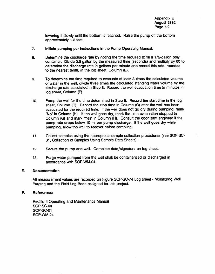
lowering it slowly until the bottom is reached. Raise the pump off the bottom approximately l-2 feet.
Initiate pumping per instructions in the Pump Operating Manual.
Deiermine ihe discharge raie by noting ihe time required to fiii a ijPgaiion poiy container. Divide 0.5 gallon by the measured time (seconds) and multiply by 60 to determine the discharge rate in gallons per minute and record this rate, rounded to the nearest tenth, in the log sheet, Column (E).
To determine the time required to evacuate at least 3 times the calculated volume of water in the well, divide three times the calculated standing water volume by the discharge rate calculated in Step 8. Record the well evacuation time in minutes in log sheet, Column (F).
Pump the well for the time determined in Step 9. Record the start time in the log sheet, Column (G). Record the stop time in Column (G) after the well has been evacuated for the required time. If the well does not go dry during pumping, mark i-. i’ NO In Coiumn (Fij. ii the weii goes dry, marii the iime evacuation siopped in Column (G) and mark Yes’ in Column (H). Consult the cognizant engineer if the pump rate drops below 10 ml per pump discharge. If the well goes dry while pumping, allow the well to recover before sampling.
Collect samples using the appropriate sample collection procedures (see SOP-SC- 01, Collection of Samples Using Sample Data Sheets).
Secure the pump and well. Complete date/signature on log sheet.
Purge water pumped from the well shall be containerized or discharged in accordance with SOP-WM-24.
7.
8.
9.
IO.
11.
12.
13.
E. Documentation
All measurement values are recorded on Figure SOP-SC-7-I Log sheet - Monitoring Well Purging and the Field Log Book assigned for this project.
F. References
Rediflo II Operating and Maintenance Manual sQp-sC-lJ4 SOP-SC-o1 SOP-WM-24

Appendix IE August IS!32 Page 73
FIGURE SOP 7-l mSHEET FOR MONITOIRING WELL PUFlGINCa =
-
-
-
-
-
-
-

Tl-!!S ?.AGE W.AS !NTENT!ONALLY LEFT BLANK

Appendix E August 1992 Page 8-1
SOP-SC-08 - Purging and Collecting Well Samples Using Bailers
A. Purpose
This SOP describes the materials needed and steps required to evacuate the standing water in the well casing prior to actual sample collection.
0. Scope
This SOP describes the procedure to be used when bailers are used to purge and/or .-II..*~~~.I*~~~-I.~. ..~..~.I.. cowc[ WBII water samples.
C. Apparatus and Materials
1 i:
C!eaned ?ei!On bai!er l/2 or 1 gallon poly container
3. Monitoring well log sheet 4. Clean twine or string 5. Alconox and 10 gallons of deionized water 6. 2-5 gallon buckets 7. 55 gallon drum to collect purge water (if required by SOP-WM-24)
D. Procedure
‘,:,, 1. Measure the distance to the surface of the water following the procedure in SOP- SC-04 if the well does not have a data logger device installed.
2. natarmins +&-.a r(an+i. rr‘ the *.,,a,, *.,3+nr h., rL#h+ve.+inn +4-a. Air+~nr,2 +m tka \.r3+a* Yl.ll,lUll” ..a.2 Yvp’I VI WI” .su11 Y.U.UI “1 ~Y”.‘““L”‘~ L,IU “IIIuaI”” .” ..I” V.U.II obtained in Step 1 from the depth of the cased hole [log sheet Column (A)]. Round to the nearest tenth of a foot and record in log sheet, Column (C).
3. Calculate the volume of water standing in the well by the formula. For 3” diameter wells - (depth calculated in step 2) x @@j = gallons. Round the calculated volume to the nearest gallon.
4.
5.
Record the calculated volume of standing water on the log sheet, Column (D).
Multiply the calculated volume of standing water by 3 and enter this value in Column (D), volume to be purged, of the log sheet.
I-:.:-.- L-:8:-- L.. ^I -... I.. I -...-_ :-_ .L- L^:l-- . . . . :I :* -^..1^^1^ .L^ . ..-.-- ^..A..^^ IIIllW,ci “allllly uy sluwly wwt;,lr~y ,I,0 “cllltn “I1111 II L.wIILcIlA* LIlti WQLril 3”IIsllrcI. Lower the bailer into the water. Raise the bailer and pour the water into the l/2 or one gallon container to measure the amount removed. Continue the process until the “volume of water to be purged” entered in Column (D) has been removed or the well OO~S drv. Ii the well goes dry, mark a ‘Yes” in Column (H). record the .L-- -~ I~ I. ~---~-~ amount of water removed, and allow the well to recover before sampling.

Appendix E August 1992 Page 8-2
a. Secure the well. Complete date/signature on log sheets.
9. Dispose of pure water in accordance with SOP-WM-24.
E. Documentation
F. References

Appendi:K E August 1992 Page 8-9
FIGURE SOIP 8-l w SHEET FOlR MONITtYMNG WELL PURGlNlG
-
-
-
-
-
-
-

.
THIS PAGE WAS INTENtiONALLY LEFT BLANK

Appendix E August 1992 Page S-l
SOP-SC-09 - Collecting Water Samples from the IWD
A. Purpose
This SOP describes the material needed and the steps required to collect water samples from the Industrial Waste Ditch.
0. Scope
This SOP describes the procedures for collecting water samples from the IWD.
C. Apparatus and Materials
1. Long handled teflon scoop 3 2 . 5 nallnn stainless steel htcknts
3: - =-“-.’
_._.____ _.__ ---..-.-
Alconox and 10 gallons of Deionized Water 4. Rubber gloves 5. Sample bottles 6. Field Log Book 7. Sample labels and seals
D. Procedures
- ,- 1. Pour 2 1 /z gaiions of deionized water each into 6 gaiion stainiess sieei buckeis.
Add a small amount of Alconox to one bucket.
2. Wash a long handled scoop in the Alconox water and rinse with clean deionized \A,l+Pr ,,“..a,.
3. Clear the vegetation from the area of the Industrial Waste Ditch (IWD) from which the sample will be taken. This area should be as close to the center of the IWD as can be reached with the scoop.
4. Obtain a full scoop of water from as close to the bottom of the IWD as possible without disturbing the sediments on the bottom of the channel.
5. Fill the sample bottles. Add appropriate preservatives and ciose the botties. The preservatives added to the samples will vary with the type of sample. Consult the instructions sent by the vendor. Seal the bottles with Para-film. Place both the sample label and seal on the bottles, ensuring that all information is accurate. n --^_ -I .L^ ^^--I^ ^^11^^,:^- :” a... Ci^,A I ^,-. q rr,, ntx.u,u II Ic: xlllq.n’i b”IIVbLI”I I II, $1 tlj rlra” L”Y “““R.

.

Appendix E August 1992 Page 10-l
SOP-DR-10 - Monitoring Well Development
D11rnncn A. . -.r---
This SOP describes the procedure for ground water monitoring well development.
B. Scope
This SOP is applicable for all ground water monitoring wells.
C. Apparatus and Materials
1. Westinghouse approved drill rig, air compressor, and related accessories. 2. A surge block fitted with a flapper valve and associated rigging. 3. A submersible water pump or compressed air line. 4. Electrical measuring tape.
D. Procedures
1. Completed wells shall be developed using a surge biock which iS equipped with a flapper valve. The surge block shall be constructed to fit snugly into a 3 inch inside diameter PVC casing.
2. T’ne surge biock shaii be insertea lrixa me weii such ihc3t puiiiiig oii iiis biDCk W/Ii * L .I-
.,., . . create suction. The block shall be forced to the bottom of the well and pulled out several times. The surge block shall be removed from the well.
2. A -..L-___!I,_ ___-_ __ ___^^.._ :_.. n suomerswe purrtp UI prawur~~w 011 WL~I u-4 UJCU LU TV~~UU~.LW =+~uvA~~~s--sJ L-II A ^:. ,.A,, I-^ ,,....A +- r*,rr,,..,*a ~nnrrr”;ml+n,,, +nn
casing volumes of water from the well. The casing volume will be determined as detailed in SOP-SC-07.
4. TL- -*a~-~ kl~.rb ,.,ill +knn kn rain+mAt,rar( in+n +hn (~01) in +ha nnnnsi+e dirap+inn ag I llrj rJu,yr; “,“Crx Sill, ,,,ra, UC ICIIILIV”“““” I8I.V .II” ..“II I.0 . . ,” -rr--..- -.. --..-. -- before such that pushing the block into the well forces water into the formation. The block shall be forced to the bottom of the casing several times. The surge block shall be removed from the well.
5. A submersible pump or pressurized air will be used to evacuate approximately ten casing volumes of water from the well.
fi “. Steps 2 through 5 shai! ha reoeated until the water is clear or as directed by -- .-r . -- .~~~~ Westinghouse.

.
THIS PAGE WAS INTENTIONALLY LEFT BL4tiX

Appendix E August 1992 Page 11-l
SOP-SC-11 - Sieving Samples in Preparation for Analysis
A.
8.
C.
Purpose
This SOP describes the materials needed and the steps required to sieve samples in preparation for an -.,-.-. dv~ici
Scope
This SOP describes the procedures for sieving gravel samples prior to analysis so that a more accurate accounting of the potential contaminant content can be made.
Apparatus and Materials
:: U.S. Standard Sieve size #230 Decontaminated teflon bucket
D. Procedure
1. Recover gravel to be sieved from sampling device; about 2 to 4 pounds.
2. Slowly pour the gravel into the sieve. Gently shake the sieve, taking care to minimize the amount of dust released. Collect ?he materia!, which passes !hrough the sieve in a teflon bucket.
E.
3. Continue sieving until 500 grams of sample has been gathered.
4. Transfer the sample to new bottles and process the samples in accordance with the applicable sample data sheet (see SOP-SC-01 for list of data sheets).
Documentation
All activities shall be recorded in the field log book assigned to the project.
.
THIS ?.AGE WAS !NTENT!ONALLY LEFT S!ANK

Appendix E August 1992 Page 12-1
SOP-SC-12 - Rinsing Gravel Samples with Nitric Acid
A. Purpose
This SOP describes the material needed and the steps required to rinse gravel samples with nitric acid and collect the rinsate for analvsis. ~~I-
0. Scope
This SOP describes the procedures for rinsing gravel samples with nitric acid, and the subsequent collection of the rinsate for analysis.
C.
0.
Apparatus and Materials
1. Two iiters of iO% niiric acid 2. Two liters of deionized water 3. 2 gallon teflon bucket 4. Rubber gloves 5. Gnnnlar 6. --==‘-- Acid resistant apron 7. 1 - Large teflon funnel a. Large diameter, 50 micron fiberglass filter paper 9. 1 gallon amber small mouth glass jar with teflon lid
Procedure
1.
2.
3.
4.
5.
6.
7.
8.
Collect 5 pounds of gravel which has previously been sieved in accordance with --- -- sup-SC;-i i.
Pour the gravel into a two gallon teflon bucket.
De,,r 1 ,i+mvr d ,nw nitrir CM&l ,u,e.* +b.n “,~~,c.l 3nrl ,.,%-.+I,, rni” ‘A. 9 m:n,*+,sr I ““4 L ,,,r,i) “I I”,” 111\11u ““0” “l-0 \IIW y”“m, Ull” y”‘L’y II,,,% I”, L 11IIIIU.~~.
Decant the solution through a funnel lined with a 50 micron fiberglass filter into a 1 gallon amber glass bottle.
Pour 2 liters of deionized water over the gravel and gently mix.
Decant the water as in step 4 above.
Discard residual gravel in accordance with SOP-WM-24.
Collect and process the liquid sample for shipment in accordance with sample data sheet 2, Total Metals in Liquid Matrices.

Appendix E August 1992 Page 12-2
E. Documentation
Record all activities in the assigned field log book and complete the sample data sheet and Chain-of-Custody Forms.
.
Appendix E August 1992 Page 13-1
SOP-IO-13 - Collecting and Reducing Gravimetric Readings
A. Purpose
This SOP describes the materials needed and the steps required to collect gravimetric readings, and the steps needed to reduced the data to a usable form.
B. scope
This SOP describes the procedures for operating a microgravimeter.
C.
D.
Apparatus and Materials
1. Microgravimeter 2. I aI,c.l:nP. k.lra ~l~+s LI”w111’y “DII pa. 3. Location map 4. Pen - indelible ink 5. Field Log Book 6. Log sheet SOP-IO-I 7. Watch
Procedures
1. Using a map annotated with the station location, proceed to well NRF-7. The brass marker set in the concrete pad will act as the Primary Base Station (PBS). Collect a measurement in the following manner:
Place the gravimeter on the concave plate and grossly level the instrument. Use the net screw tn finish Ievnlinn the nravimeter~ _.._ ______.. ._ .._. ._- . . .._ .._ _._.~..~.....
Null the meter by releasing the set screw and turning the adjustment knob until the red line is to the right of the pointing arrow. Turn the adjustment knob slowly until the line is exactly lined up with the pointing arrow. Read and record the time and measurement on Figure SOP-10-13-I.
2. Collect measurements along the path described below, ensuring that the time between collecting measurements at the base station does not exceed two hours.
From the PBS, proceed east to grid intersection D4, collecting measurements at 100 foot intervals (station locations will have been surveyed and marked previously).
Continue collecting measurements from grid intersection 04 along the following path: D5, C5, C4/PBS, C3, 03, 04, C4/PBS, 84, 83, C3, C4/PBS, C5, 85, 84,

Appendix E August 1992 Page 13-2
C4/PBS. Measurements at C4/PBS will be collected regardless of the amount of time elapsed since the last measurement at that location. Duplicate measurements at previously occupied stations will be limited to stations at grid intersections only. Stations located between grid intersections will not be measured again.
Always end the day by collecting measurements at all Secondary Base Stations (SBS) occupied between the time of the last PBS measurement and the last station measurement. The last measurement of the day should be collected at the PBS.
3. Immediately after collecting the last measurement at C4/PBS, proceed to C6 and collect a measurement. This location will be designated as Secondary Base Station 1 (SBSl). Adhering to the general guidelines discussed in section D2, coiiect measurements along the following path: D6, D7, C7, CG/SBSl, C5, D5, D6, CX/SBSl, B6, 85, C5, C6/SBSl, C7,87,66, CG/SBSl.
4. Immediately after collecting the last measurement at C6/SBSl, proceed to C8 and ..^I,^?.4 ̂ -^r^..~^l^^^. Tl.L. I^^^*:^^ ,.,:o L^ -I^^:--^*^-1 ^^ c. ̂ ^^^ -I^.... me-- V”IIOC1 a IIITaaUtTIIIw I,. l lllJ I”l.aLI”II “*Iat UC? “c2lylwxs;” a3 ~~L”r~“aly Pa3ts Station 2 (SBS2). Adhering to the general guidelines discussed in section 02 above, collect measurements along the following path: D6, DS, CS, CS/SSS2, C7, D7, Df3, C6/SBS2, B6,87, C7, C0/SBS2, CS, BS, B0, C6/SBS2.
5. Immediately after collecting the last measurement at CS/SBS2, proceed to Cl0 and collect a measurement. This location will be designated as Secondary Base Station 3 (SBS3). Adhering to the general guidelines discussed in section D2 above, collect measurements along the following path: DIO, Di 1, Cl I, ClO/SBS3, CS, DS, DIO, ClO/SBS3,810, B9, C9, ClO/SBS3, Cll, Bll, 810, ClOfSBS3.
6. Proceed to Cl 1. Adhering to the general guidelines discussed in section D2, _-1#__1 -- --.._ ____I_ _I--- AL_ z-11 _.. ?-- -_.L_ ,-.a* _.L _a. _A, n-e.. -,A ci”llcIGl III~as”reIrILIIILs alully kilt: l”ll”wlrly pew,; b IL, u IL, u I I) b I I, 3c)33, b I , , C12,B12,B11,Cll,SBS3,Bll,B12,A12,All,B11,SBS3,B11,All,A10,B10, Bll, SBS3, BIO, AIO, AS, BS, BlO, SBS3.
!mmedil_!e!v after ~o!!e&n the lnet maaatwamant at SRSR nmreed tn CR!23 am-l , -..-. - . ..- .--. ..----.-...-... -. _-__( r. - -- - - .- - - -- -. - collect a measurement. Adhering to the general guidelines discussed in section D2, collect measurements along the following path: 96, 89, A9, A6, B6, SBS2, 86, A6, A7, 87, B6, SBS2.
6. Immediately after collecting the last measurement at SBS2, proceed to SBSl and collect a measurement. Adhering to the general guidelines discussed in section 02, collect measurements along the following path: B6, A6, A7, 87, B6, SBSl, B6, A6, A5, 85, 86, SBSI.
9. Immediately after collecting the last measurement at SBSI, proceed to the PBS and collect a measurement. Adhering to the general guidelines discussed in section D2, collect measurements along the following path: 84, 85, A5, A4, 84.

10.
11.
12.
13.
14.
15.
16. Reduce the gravimetric data as described in the books referenced in section F of this SOP.
17. Determine the drift correction as follows:
Appendix E August 1992 Page 13-3
05, PBS, 84, A4, A3, 83, 84, PBS, 83, A3, A2, 82, 83, PBS, 83, 82, C2, C3, 83, PBS, D4, E4, E3, D3, D4, PBS, D4, E4, E5, C5,D4, PBS.
Immediately after collecting the last measurement at the PBS, proceed to SBSl and collect a measurement. Adhering to the general guidelines discussed in section D2, collect measurements along the following path: D6, E6, E5, D5, D6, SBSl, D6, E6, E7, D7, D6, SBSl.
Immediately after collecting the last measurement at the SBSI, proceed to SBS2 and collect a measurement. Adhering to the general guidelines discussed in section D2, collect measurements along the following path: D6, E8, E7, D7, D8, --A^ -^ v.. -- ^^ ^^ A^^- ot¶oz, “0, ea, EY, “3, “0, 5t152.
Immediately after collecting the last measurement at the SBS2, proceed to SBS3 and collect a measurement. Adhering to the general guidelines discussed in rcwiinn n9 mllca-i mcca~~w.arncm+~ dnnn +ha fnlhwinn rr=+k. n-n ElrT CO no .,.,.,..-.. --, ““!.““. .11”%.““.~11I~.I.” %.,v*,y WI” 1”““vv”‘y you,. Y ,“, L,“, w, vu DlO, SBS3, DlO, ElO, Eil, Dll, DlO, SBS3, Dil, Eli, E12, D12, Dll, SBS3, SBS2, SBSl, PBS.
Immediately after collecting the last measurement at the PBS: proceed to F4 and collect a measurement. This location is now Secondary Base Station 4 (SBS4). Adhering to the general guidelines in section 02, collect measurements along the following path: G4, G5, F5, F4/SBS4, F3, G3, G4, F4/SBS4, E4, EE3, F3, F4/SBS4, F5, E5, E4, F4/SBS4.
Immediately after collecting the last measurement at the SBS4, proceed to F2 and collect a measurement. This location is now Secondary Base Station 5 (SBS5). Adhering to the general guidelines in section 02, collect measurements along the ‘n,,nl.,in” nr+l.. I?? p_r) r.7 C”/Pc)P~ c4 rT.8 -0 Cn/CICIClc Cn c. Fl 1”“““““‘y pau,. UC, “4, 8 4, tr,z,uuclil, r I ( ” I( “6, ‘L,\30a31 Lq CI, TN3 F2/SBS5, F3, E3, E2, F2/SBS5, F4/SBS4.
Immediately after collecting the last measurement at the 5854, proceed to F6 and collect a measurement. This location is now Secondarv Base Station 6 r.SB.S6\. Adhering to the general guidelines in section D2, collect measurements along the following path: G6, F5, G5, G6, F6/SBS6, E6, E5, F5, F6/SBS6, F7, R, E6, F6/SBS8, F4/SBS4, PBS.
Construct a plot, on standard graph paper, of raw gravity readings from like base stations on the x-axis versus time on the y-axis.
S&&a_C! from the .SB.S readinns an amount e”“a! t” the &ferencp in <pa&n” values between adjacent SBS collected at or very near the same time. Stan with the SBS which was time wise, the most distant from the PBS reading.

Appendix E August 1992 Page 13-4
Sequentially follow this procedure back to the PBS reading, The result shoutd be one continuous curve referenced to the first reading collected at the PBS at the beginning of each day. The difference between the first reading collected at the PBS at the beginning of the day, and a reading off the curve at a given time is the correction to be applied to station readings collected at that time. Values above the time zero PBS reading are subtracted from the station values. Values below the time zero PBS reading are added to the station values.
E. Documentation
All measurement values are record on Figure SOP-10-13-I Figure I, Log Sheet for Gravimetric Data Collection.
F. References
Dobrin, M. B., Introduction to Geophvsical Prosoecting, McGraw-Hill, 1976 Telford, W. M., et. al., Aoolied Geoohvsics, Cambridge University Press, 1982
.

Appendix EI August 1992 Page 13-5
FIGIJRE I - Log Sheet for Gravimetric Data Collection

THIS PAGE WAS INTENTIONALLY LEFT BLANK
Appendix E August 1992 Page 14-1
SOP-IO-14 - Collection of Resistivity Data
A. Purpose
This SOP describes the materials needed and steps required to perform a resistivity survey using the Schlumberger and Werner arrays.
6. Scope
This SOP describes the procedure to be used with a DC resistivity meter in both depth sounding and profiiing procedures.
c. Apparatus and Materials
1. nr rarir+i.,i+l, mstnr n.rrknr onA r.zklnc ,rnnn ‘an, n+ rakla mc.vim,,m\ Y” ““‘L!““y lllW.ll, y l”“IIl c&II” “CIUIU~ \‘““V IUUL “8 “cavlr !““““‘,U”‘, 2. 2 to 5 pound sledge hammer 3. 10 gallons of CuSO, 1 molar solution
D. Depth Sounding Procedures
Werner Array - Depth Sounding
1.
2.
Select the area to be surveyed, avoiding metallic objects.
Set up the electrode array using an (a) spacing of 5 feet. The (a) spacing is defined as the distance between electrodes. With the Werner array, this distance is constant.
3. Pound the electrode into the ground using a sledge hammer. The electrode should penetrate the ground surface at least six inches.
41
5.
Pour nnnmximntelv 250 ml of C&O. solution at the base of eaoh electrode, _pp ._......_._. , -__ _ ___-*_-~_.~_
Measure the potential between electrodes and record the results in Figure SOP-IO- 14-t.
6. Increase the (a) spacing by 5 feet and repeat steps 3 through 5. Continue steps 3 through 6 until desired results are achieved.
Schlumberger Array - Depth Sounding
1.
2.
Select the area to be surveyed, avoiding metallic objects.
In using the Schlumberger array for depth sounding, the potential electrodes mmain fiund while thn PI wrnnt elc.ctmric. cnarinn ic r?unanriwi cvmm~tricall~, &nc! .-...-... ..I._” . . . ...1 . ..- --..-... _.” -..- I- lr --...= .- -,.r”. .“_” -,. . .-...--..,
the center of the array. The potential electrodes are symmetrically placed about

Appendix E August 1992 Page 14-2
the center of the array 5 feet apart. Initially, the current electrodes are spaced 10 feet from the center of the array.
3. Pound the electrodes into the ground using a sledge hammer. The electrodes should penetrate the ground at least six inches.
4. Pour approximately 250 ml of CuSO, solution at the base of the electrodes.
5. Measure the potential between electrodes and record the results on Figure SOP- 10-14-I.
6. Increase the spacing between the current electrodes by 10 feet and repeat steps 3 through 5. Continue steps 3 through 6 until the desired results are achieved.
Werner and Schlumberger Arrays - Profiling
1. Select the area over which the array is to cross, starting at one end. Ensure that the profile path does not cross an area enriched with metal.
2. Using the ideal electrode spacing determined above, set up the arrays as - described by steps 3 and 4 of the above descriptions. Collect readings as above moving the center of the array 5 feet after each measurement. The spacing between nkxtrodns rnmainrr cnnstant. Record the rer;u!ts for ea_& mga_~uremnnt~ - _ _ _ ___.._ -__ ._ - .._ _ _ _ _.
E. Documentation
All measurements values are recorded on Figure SOP-10-14-I Log Sheet - Resistivity Data.
F. References
Dobrin, M. 9, Introduction to Geoohvsical Prosoectinq, McGraw-Hill, 1976
Telford, W. M., et. al., Aoolied Geoohvsics, Cambridge University Press, 1962

Appendix E August 1992 Pagfr 14-3
LOG SHEET - RESISTIVITY DATA
I
TIME F SPACING-l- (a) SPANG[ INSTRUMENT T READING SETTING

.
T!-!!S PAGE WAS INTENTIONALLY LEFT BLANK

Appendix E August 1992 Page 15-1
SOP-DP-15 - Heavy Equipment Decontamination
A. Purpose
This section describes the decontamination procedures to be followed when cleaning buiidozers, trucks, and backhoes.
B. Scope
Thie &mn+nmins+inn nmfxwh tr.3 ie ~nnlir~hln tn rl~~nntswninst~ haznnr *n* h-,m,3n+ c> w-h ZIF ..- __““...... . . . . ..-. r.--.,-“. - .., “rr’..,..‘.- .., ““WV. 11”s IS>1 .“I” I .“..., “y”P”“‘a”a I., “““8 I u.. bulldozers, trucks, backhoes, and drill rigs. Personnel assigned to perform the decontamination of sampling equipment will be briefed in the use, limitations, and safety considerations of the decontamination procedures.
C. Discussion
The methods generally used are steam cleaning or washing heavy equipment with water under high pressure, and/or scrubbing accessible parts with detergent and water solutions under pressure. Particuiar care must be given to those components in direct contact with contaminants, such as tires and scoops.
D. Materiels
1. Wire and/or nylon scrub brushes
2. Tap water source
3. Non-phosphate detergent (such as Alconox)
4. Deionized water
5. Steam cleaning equipment
6. Teflon wash bottles filled with isopropanol
7. nz- __I_ __SI__I!_- _I-..:-_ IL_I_I~ -_-I 1-- -.-.-- -!-.A ..~~~Y~._..~.. .~._I .--.,I I-- nwww liu~~txiwr~ uewe puoy puut rur meu~um SILBU equ~prrum ano small oowi for small equipment) and 55 gallon drum for solution disposal.
E. Procedure
The decontamination procedure for heavy equipment is as follows:
1. Remove bulky material adhering to the item using nylon scrub brushes or wire brushes. If necessary, use water and non-phosphate detergent (such as Alconox) to assist in dislodging and removing contaminated material.

Appendix E August 1992 Page 15-2
2.
3.
Rinse the equipment thoroughly with potable water.
Steam clean the item in accordance with equipment-specific operating and maintenance procedures.
4. Check sampling equipment for any particles adhering to the side; use a brush to dislodge any particles. If particles are detected, repeat step number 3 in the procedure.
5. Use isopropanol to rinse the equipment if it is suspected that organic contamination is present.
6. Rinse the decontaminated iiem wiih deionized waier. Coiiect one rinsate sampie for each 20 soil samples collected. If practical, allow cleaned equipment to air-dry indoors, or within an area protected from wind-blown dust.
l?eCOrd!!!g
A field sampling logbook will be used to document the date and time of decontamination, all sampling equipment used, and any deviations from the decontamination process listed above.
G. Dispose1 of Cleaning Solutions
The final disposal of rinse water and material dislodged from sampling equipment will depend on ina area sampied, known or suspected contaminant ieveis, and tne proximity of the decontamination area to the sampling area. (See SOP-WM-24)
The isopropanol rinse solution will be collected and placed in a 55 gallon drum for ana!ysis and fIu?lJre disposa!.
H. References
U.S. Department of Energy, 1959, Environmental Survey Manual, Appendix G: Office of Assistant Secretary, Environment, Safety and Health, Washington, DC. 20585, Office of Environmental Audit, DOE/EH-0053, Second Edition, January.
SOP-WM-24

Appendix E August 1992 Page 16-1
SOP-DP-16 - Sample Equipment Decontamination
A. Purpose
This section describes the decontamination procedures to be followed when cleaning sampling equipment. Rinsate samples (1 in 20) of a final deionized water rinse will be coiiecied for anaiysis to provide quaiiiy assurance (CMj ior tine deconiaminaiion method.
B. Scope
This dec~n!amination nmrad~ we ic annficshla !g &c~n!amin$e rlinnere nnnd ca-nnl~rc I-.-----.- ‘- -e-r-“---‘- -.fr -.-, r -..- -“...r.“.“r
scoops, split-spoon samplers, sleeve liners, and any other devices used to obtain samples of surface water, sediment;soil, or sludge. Personnel assigned to perform the decontamination of sampling equipment will be briefed in the use, limitations, and safety considerations of the decontamination procedures.
C. Discussion
All reusable equipment will be decontaminated before and after use. Also, whenever possibie, disposabie equipment and coniainers wiii be used io minimize fieid decontamination requirements, thus saving time and money, reducing the potential for cross contamination, and minimizing the waste solvents that require disposal.
1. Wire and/or nylon scrub brushes
2. Tap water source
3. Deionized water
4. Non-phosphate detergent such as Alconox
5.
6.
Teflon wash bottles filled with isopropanol
Rinsate collection device (kiddy pool for large equipment and small bowl for small ^_.. :--^-.\ ^^d cc _-II__ A__.- I-- _^I ..-- * 4: -----I aq”qJ’rlrln, all” aa yoll”lI “l”lll !“I s”I”e,II “yJ”S.al
E. Procedure
The decontamination orocedure for samoijnn eouioment used for oroanic and inoroanjc sampling is as follows:
1. Remove bulky material from the equipment with tap water and rinse with pressurized or gravity flow tap water. Nylon scrub brushes or wire brushes may help in removal of material.

Appendix E August 1992 Page 16-2
2. Wash and scrub the equipment thoroughly with a non-phosphate detergent (such as Aiconox) and iap waier.
3. Rinse the equipment thoroughly with tap water.
d r?hnrk cmnnlinn c,“, ,inmant 4-r *n*, ..rr*irb.r ^Jt. _. -. ,““.. ‘“.,,y.” ,y ‘y”‘p’“‘I. I”3 a, my ~o.‘Ilrlr~ a”4 1cJ1II ‘y L” ,I 1lz J “Ei, UJ13 a “l”Jll L” ..A^- I^ Il.,. ,+I^. ..^^ ^ L _..-L .-
dislodge any particles.
5. Triple rinse with deionized water.
6. Using Teflon wash bottles, spray-rinse all surfaces with isopropanol. Collect the isopropanol in a container for disposal. If the rinsate sample is required for QA, make an additional final rinse of the item, using deionized water, and collect it for analysis. If practical, allow cleaned equipment to air-dry indoors, or within an area protected from wind-biown dust.
F. Recording
I3 ‘id,4 ce,mn,:nn ,rr”k~d, Id,, he . ar..rl .^ A^^. .,.......I IL.. A r. ll”,” ‘.A”‘pm”y ‘“y”““” v.111 Y uIlru Iv uuti~~ I urn II LO I= die and time Of d~COiii&diiaiiOr7, all sampling equipment used, and any deviations from the decontamination process listed above.
G. Dispoeal of Cleaning Solutions
The final disposal of rinse water and material dislodged from sampling equipment will depend on the area sampled, known or suspected contaminant levels, and the proximity of the decontamination area to the sampling area. (See SOP-WM-24)
The isopropanol rinse solution will be collected and placed in a 55 gallon drum for analysis and future disposal.
H. Refeiencas
U.S. Department of Energy Environmental Survey Manual, Appendix G. Office of Assistant Secretaly. Environment, Safety and Health, Washington, DC. 20585, Office of Environmental Audit, DOE/EH-0053~ Second Edition, January 1969.
SOP-WM-24

Appendix E August 1992 Page 17-1
SOP-DP-17 - Drilling Equipment Decontamination
A. Purpose
This section describes the decontamination procedures to be followed when cleaning drilling rigs and tools to prevent cross contamination. Decontamination of the drilling rigs and tools will be completed prior to the start of drilling operations for each borehole to prevent contamination from one borehole to another.
B. Scope
This decontamination procedure is applicable to decontaminate the drilling rig and drilling tools. Personnel assigned to perform the decontamination of sampling equipment will be briefed in the use, limitations, and safety considerations of the decontamination nmcec-ll ,re.s p. - - - - -. - -.
C. Discussion
All drilling tools will be decontaminated daily and/or before use on a new borehole. The drilling tools will be decontaminated prior to drilling into the section of borehole that will be within the well intake. This will minimize the possibility of contaminating the potential producing zone. The drilling rig will be decontaminated prior to drilling each borehole. If a hydraulic line ruptures during drilling, work will stop, the bit will be removed, and rig moved away from ihe sampiing iocaiion. Tine rupiured hydrauiic iine wiii be fixed and tine whole drilling rig will be decontaminated, along with the augers, before drilling can continue at the borehole.
1.
2.
3.
4.
5.
6.
7.
Wire and/or nylon scrub brushes
Tap water source
Non-phosphate detergent (such as Alconox)
Deionized water
Steam cleaning equipment
Teflon wash bottles filled with isopropanol
Rinsate collection device (kiddy pool for large equipment and small bowl for small equipment) and 55 gallon drum for solvent disposal

Appendix E August 1992 Page 17-2
E. Procedure
The decontamination procedure for the drilling rig and drilling tools is as follows:
1. Remove bulky material adhering to the item using nylon scrub brushes or wire ~.~ ~~ .I~~-- \ brushes. ii necessary, use water and non-phosphaie deiergeni jsucn as n~conox, to assist in dislodging and removing contaminated material.
2.
3.
Rinse the equipment thoroughly with tap water.
Steam clean the item in accordance with equipment-specific operating and maintenance procedures.
4. Check sampling equipment for any particles adhering to the side; use a brush to dislodge any particles. If particles are detected, repeat step number 3 in the procedure.
5. Use isopropanol to rinse the equipment if it is suspected that organic contaminaiion is preseni.
F.
6. Rinse the decontaminated item with deionized water. Collect one out of 20 rinsate samples for analysis for QA. If practical, allow cleaned equipment to air-dry inrlnnrc nr witkin I” *rosa nrnth-+.arl trnm winA.h,nwn ,i,,r+ I....““Iw, “. . . ...*... -.. “.-- r.v ..,.,...” . . . . . . . . . ..- 1.-11.. ---..
Recording
A field sampling logbook will be used to document the date and time of decontamination, all sampling equipment used, and any deviations from the decontamination process listed above.
G. Disposal of Cleaning Solutions
The final disposal of rinse water and material dislodged from the sampling equipment will depend on the area sampled, known or suspected contaminant levels, and the proximity of the decontamination area to the sampling area. (See SOP-WM-24)
The isopropanol rinse solution will be collected and placed in a 55 gallon drum for analysis and future disposal.
H, References
U.S. Department of Energy Environmental Survey Manual, Appendix G, Office of Assistant Secretary, Environment, Safety and Health, Washington, D.C. 20585, Office of Environmental Audit, DOE/EH-0053, Second Edition, January 1989.
SOP-WM.24

Appendix E August 199.2 Page 18-1
SOP-D%18 - Well and Borehole Abandonment
A. Purpose
This SOP describes the procedure for abandoning cased and uncased wells and boreholes.
8. Scope
This SOP is applicable for all drilled wells and augered boreholes which will be abandoned.
C. Apparatus and Materials
1.
2.
3. 4. 5.
Portland cement rfWturt? as described by Contract SpeCiiiCaiiOnS or by tiniS document. A 1 to 1.5 inch polypropylene (or Westinghouse approved equivalent) tremie pipe of sufficient length to reach to the bottom of the well or borehole that is to be abandoned. A large galvanized steel tub capable of holding up to 1 yard of cement. A cement pump and associated piping. Westinghouse approved air compressors, generators, casing removal equipment ---I --I-.--I ^-^-^^^_ :^^ a, I” I e’lcl,eu C1L&txY~“I Ien.
D. Procedures
1. If the borehole is located 25 feet or more from the IWD, and does not penetrate the surface of bedrock, the material excavated from the hole shall be returned, as described i~ snp-w?J-24, Cuejnn~ Shall be returned at nnnrnximntnlv the same il- -“-.. __ -PP.- . -_-_, .._ depth from which they were removed.
2. Cuttings shall be shovelled into the surface casing, if present, until the hole is filled to approximately the bottom of the casing.
3. The casing shall be removed in 20 foot sections, and step 2 shall be repeated. Both steps 2 and 3 shall be repeated until all the casing has been removed and the hole is filled.
4. Boreholes that are located within 50 feet of the IWD, and all drilled wells shall be grouted.
5. Any surface casing present shall be removed by pulling the casing or any other method necessary as approved by Westinghouse.

Appendix E August 1992 Page 18-2
6. Grouting of the hole shall be performed using a mixture of 20 parts Portland Type II cement to 1 part bentonite. The grout shall be mixed with water in a ratio of 5 to 7 gallons of water per 94 pound bag of cement. if addiiives are used, they ST iii be calcium chloride and “Gil-Seal” or an approved equivalent. No more thar 36 calcium chloride or 20% “Cal-Seal” shall be used in the mixture.
7. Tine tremie pipe shaii be iowered io near me DULLUI I! UI LI IC: I IUIC~, a.~ IU LI I= 31 VUL A,.- ,..y_- _‘IL_ ,-_I_ ^_A .L- __^,, *
shall be pumped in under pressure. The tremie shall be raised while the hole is filling such that the end of the tremie pipe is at or near the surface of the grout. This shall be determined by plunking the borehole.
8. The borehole shall be grouted to the surface in one continuous operation.
9. The grout shall be allowed to stand for 15 minutes. If the level of the grout in the L.--- A---- -AAi+inn~l nrnsit ck.all ha ~r4rk.A tn thn hnmhnla ,dp,!i! the !es/e! is UVIW u,upr, ~~Y,L,“,,“I Y’YY. I ,,%.,, “” ..--“.. .., . ..” I_._.._._ maintained at the surface.

Appendix E August 1992 Page 19-l
A.
0.
C.
D.
SOP-SC-19 - Chain-of-Custody Procedure
Purpose
This SOP provides the requirements for the completion of the Chain-of-Custody forms which are required for all environmental field samples collected in support the Federal Faciiity Agreemeni Conseni Order.
Discussion
A r-k.4n~“‘~P,,r+nA,, ‘nr,.... . ...,*, I.,. r^-..l^+^A ,.l...irr ,b.^ ^^I,^-.:^.. “....A a-^-^--d-I:-- -‘ -II n ““cw’-“‘-““uL”“~ l”llll lll”UI UT L.,“l~qJ~rm” ““lllly LIIcj Ir”IIcit.LI”II alI” Llallsl.‘“l,au”l# “I a,, environmental field samples. The form will be initiated at the sample collection point and will accompany the sample to the point of receipt at the analytical labora!cry.
Responsibilities
The sample collector shall initiate the Chain-of-Custody form at the sample collection point. Subsequently, the person relinquishing custody of the sample and the person accepting custody will document the exchange of the sample each time the responsibility of the sample is transferred for packaging or shipment (see Item 11 of the Chain-of- Custody procedure and form). The receiving laboratory will be document the final acceptance of custody of the sample and will return the Chain-of Custody form to the Field Contact.
Chain of Custody Procedure
Items 1 - 10 are to be completed by the sample collector
1.
2.
3.
4.
5.
6.
7.
0.
Enter the date and applicable page numbers.
Provide the laboratory name and point of contact.
Make a separate entry for each sample taken, including unique sample number, date, time, and location sampled.
On the vertical axis, list the testing parameters to be performed on all samples that are inciuded on inis page. Mark ihe inierseciion oi ine sampie number with each parameter to be measured on that sample.
Indicate the number of containers included for each sample.
Include any special observations or comments for each sample, such as media type.
Complete the NRF contact information blank.
Sign the sampler signature blank, and print your name in the adjacent blank.

Appendix E August 1992 Page 19-2
9. Enter any general comments, such as time or temperature limitations in the Remark section.
10. Indicate the method of shipment of the sample.
rlr\r, ,msn+r+inn r\‘ +.lnr+a. n+ .-I ,r+nrl\r n+ thn clrmnla l”“l...-.!.-..-l. -. ..“.,“,“. “. -“-.““, “. .,.- ““‘r”.,y,w
11. Each time the custody of the sample is transferred, the person relinquishing custody will sign, and provide the date and time of the transfer.
12. The person accepting custody of the sample will sign to verify receipt.
Laboratory documentation
i3. Tire iaboratory sampie custodian accepting responsrorkty ior the sampie wiii sign, date, and indicate the time of receipt of the sample.
14. The laboratory will provide a unique number for each sample.

Appendix E August 1992 Page 20-l
SOP-W-20 - Data Validation Procedure
A; PUl?XlS&3 --I----
The purpose of this SOP is to define the levels of method validation and to offer guidance in laboratory data validation. The levels of method validation will be used by the NRF Environmental Remediation (ER) personnel and firms under subcontract to the NRF ER personnel to perform method validation of chemical analysis data. The guidance in the evaluation and validation of laboratory data will be used for gas chromatographic data, volatile and semi-volatile organic gas chromatography/mass spectrometry (GC/MS) data, and inorganic data.
B. scope
This SOP for validation of samples is applicable to all samples collected for Environmental Remediation nt IrnnP.aE Thn hIPI n+ dlirh ,hP CflmnlP rrn kn \rcdiAs+sA AansnAr nn +ha y”.y”..“.,. . -9” .“.“I ..I ..I ,111. .a I” ~“‘,.p,‘Y ““I I “I “UI,..UL”” ““p,, I”” “I I ,I lr type of tests being performed and the analysis requested.
B. Discussion
This SOP is designed to offer guidance in laboratory data validation. Data validation is the process of evaluating the quality and reliability of data from laboratory analysis. Due to the complexities and uniqueness of data relative to the specific samples and/or different types of analyses, some areas of this SOP are only able to offer general guidance rather than step-by-step procedures. Various generally accepted good laboratory practices (GLP) will provide the data validator with much of the criteria needed to validate data from non-routine analyses. Data will be validated in accordance with the procedures listed below.
C. Procedure
The data validation procedures listed below are attached to Appendix E.
EG&G IDAHO, INC. ENVIRONMENTAL RESTORATION PROGRAM SAMPLE MANAGEMENT OFFICE STANDARD OPERATING PROCEDURE NO. SMO-SOP-12.1 .l dated July 1991, will be used for establishing levels of method validation.
EG&G IDAHO, INC. ENVIRONMENTAL RESTORATION PROGRAM SAMPLE MANAGEMENT OFFICE STANDARD OPERATING PROCEDURE NO. SMO-SOP-12.13 dated August 1991, will be used for validation of volatile and semi-volatile organics analyzed by gas chromatography/mass spectrometry.
EG&G IDAHO, INC. ENVIRONMENTAL RESTORATION PROGRAM SAMPLE MANAGEMENT OFFICE STANDARD OPERATING PROCEDURE NO. SMO-SOP-12.1.4 dated August 1991, will be used for validation of gas chromatography data.

Appendix E August 1992 Page 20-2
EG&G IDAHO INC. ENVIRONMENTAL RESTORATION PROGRAM SAMPLE p/lHNH”CMC,Y , “I-rlbc 0 I n,Y”nn” “I-cnn I II”” rn”~,L”“nL I”“. .al”I”-uvr -tic. I ..J ..^.,. a.-...-.L A-,-,nr nT-...,,-.,,r,m ,TnFT-,~T,k,C nnr\Trcn,,nc p.,,? EL”n c.fil3 ,q * !z
dated September 1991, will be used for validation of inorganic data.

‘.’
A.
0.
C.
0.
SOP-DR-21 - Monitor Well Drilling
Appendix E September 1992’ Page 21-1
This SOP describes the procedure for ground water monitoring well drilling.
Scope
This SOP is applicable for all ground water monitoring wells.
Apparatus and Materials
1. 2.
3.
4. 5. 6. 7. 8. 9.
Westinghouse approved drill rig, air compressor, and related accessories. Casing, well screen, portland cement/bentonite grout, gravel pack, and related items. \&,^^*:“̂ I.^....- ^rrer.,^A ..:^^ A--- ,...llevLII^w ^i, *“A s,..,, P.+k,.r r,,hr+..“rn ““cI*LII ‘y I”“3c: q.Jp’““~” pp uupu, b”II1f./‘~JrJW “ll, cd I” at my vu &El a”uaLac Iti= which has the potential to be introduced into the borehole. A steam cleaner. Deionized water. C-r- IA!--n-v\ ‘-r *ha rlallninn n* Am.,” h,nla c.nr( m ic~aJl~“PnlIP ,an,linm~n+ ““a.(* ,rv”““““, I”, .I I_ “lczUl111 ‘y “I ““VII I I l”ll “I 8” I III.2V”In.I I”““” “y”ay’11-11.. Storage for hand tools and small pieces of equipment. A temporary cover for the hole. A locking well cover.
Procedure
1. All material to be used in constructing the wells (casing, screen, and other components! and all other equipment with potential to cross contaminate the well shall be new or cleaned in accordance with SOP-DP-15 prior to installation or use. Drill bits, casing, and well screen shall be steam cleaned using deionized water prior to use.
2. The cleaned components shall be protected. Any contact with uncleaned surface shall be reason to repeat the cleaning.
3.
4.
Perform the drilling operations as directed by the Work Plan or the Sampling Plan.
Detailed descriptive logs are to be maintained for all drilling activities. These logs shall be submitted to the project engineer at the end of each week for review.
5. No foreign sand, dirt, rock, cuttings, drilling mud, or any foreign material whatsoever, shall be introduced into the hole except with the prior knowledge and consent of the project engineer.
6.
7.
The project engineer shaii approve tine type of oii used in the air compressor.
A temporary cover shall be in place at all times the hole is unattended or the danger of objects falling into the hole exist.

Appendix E September 1992 Page 21-2
The compressed air supply to the drill string shall be double filtered to ensure that oil is not introduced into the hole.
All holes shall be drilled as straight and as nearly vertical as possible. In the .ent a hole cannot be completed, the hole shall be abandoned by filling with a cement/beritonite grout as described below.
Grouting of holes shall be done using a mixture of 20 parts Portland Type II cement to 1 part bentonite. The grout shall be mixed with water in a ratio of 5 to 7 gallons of water per 94 pound bag of cement. If additives are used, they shall be --I-.~~-. .I.,.~~..,. --_I .A-# *.-a. -. - --~---~~..1 ..~~~.I 1_1_1?L?.... -L-II _.I ~~~~. ~a GalGlum cnlorloe ano Lal-aeal or a approveo equal. bw~Rl”es snau nor exceea 20% of the grout mixture.
Abandoned wells shall be grouted to the surface in one continuous operation.
Grout shall be allowed to set up at least 48 hours before drilling is re-started. All grouting procedures shall conform to applicable State of Idaho regulations.
AI, r.arinn d-e dl.Tl,l ka inina*l +nna+bla. +n tks svtsnt that +a,., tkrsed4r ?lPe3 cknwin” -II “clllll ,y pp.2 en #a,, YW ,Y”‘WY wy’u II0 L” .I II VALII I. .I ICAL I”.. .I II I”“” SiIV -8 I”..80 ,y and no further tightening possible. The casing shall not be so deformed or crooked as to prevent any of the specified opera!ions or the setting of any doxn hole equipment. The casing shall be steam cleaned prior to installation.
Temporary casing shall be set, if needed to prevent the hole from caving, from just above the concrete well pad to the top of the basalt. The casing may be installed temporarily or permanently. Removal of temporary casing shall conform to State of Idaho regulations.
A spacing differential of at least 1 inch shall exist between the outer casing wall and the side of the borehole in order to accommodate sufficient grout.
Casing shall be pressure grouted in place via a tremie pipe. The grout shall extend to the surface. During grouting the annular space shall be kept free of sand, mud, or water.
Well screen shaltbe installed and ‘gravel packed” as directed by the project engineer. The screen shall be steam cleaned prior to installation.
A two foot bentonite grout plug shall be placed below the gravel pack and a one foot bentonite grout plug will be placed above the gravel pack. The bentonite shall be pelletized and shall be placed via a tremie pipe.
Casing shall extend two feet above the concrete well pad. The concrete pad shall be instailed along with bumper posts in accordance with aii idaho state and iocai regulations.
A well cover shall be installed to accept a standard padlock. The cap shall cover ~~~.,I .~_I___ IL_
a.
9.
10.
11.
12.
13.
14.
15.
16.
17.
18.
19.
20.

Appendix E September 1992 Page 21-3
21. All wells shall have a fixed survey marker in the concrete well pad and shall be surveyed for horizontal location to the nearest 1 .O foot and vertical location to the nearest 0.01 feet.

THIS PAGE WAS INTENTIONALLY LEFT BLANK

Appendix E, August 1992 Page 22-l
A.
8.
C.
D.
,‘:‘.
SOP-BA-22 - Borehoilng and Auguring
Puraose .-
This SOP describes the procedures for boreholing and auguring.
Scope
The scope includes auguring, collection of split spoon samples (split-barrel) and stratigraphic characterization of the alluvium and soil.
Apparatus and Materials
1. A boring/auguring rig with related equipment.
2. Stainless steel sampling equipment.
3. A split spoon sampler.
4. - .. romand cementjbentonite grout.
Procedure
i. &II --1-2-1 .- L_ ..-_A :- 1L_ L-d-- _-_I _.-..-:-- _-_I _I, --L-- fill IllaKxlal L” “V “SC10 111 l,,r: “orlrly all” auyumy all” a,, “Lrler equipment Wltii potential to cross contaminate the samples shall be cleaned in accordance with SOP-DP-17 prior to installation or use.
2.
3.
4.
nnra ,.kia#.+r kn,a 6.ae.n rlarnsrl ,ka.r rkrll I... re,.+r.e+rrl ?,-,.I I- ̂ .., ^I^^- “I IYI ““,‘“L’ I ICIIV “TsiII UlrCll IW” LI “y .a# lclll VW p”L’u”” CII I” fv+L c4lza.I t. All contact with uncleaned surface materials shall be reason to repeat the cleaning.
Stainless steel sampling equipment (scoops, screens, bowls, trays, etc.) shall be rband zx cnarifid in .QnP.DP.!fi _ Snmnln Fntdnmnnt ncwnntnminrrtinn -.--..-- -- -r --.. *-- . . . --. -“...r.- -y”.r...-... I~-~...-...I..-.I”...
The disposition and control of auger cuttings shall be in accordance with SOP- WM-24.
5. No foreign material whatsoever shall be introduced into the borehole during boring and auguring except with the prior knowledge and consent of the project engineer.
6.
7.
The project engineer shall approve the type of oil used in the air compressor.
A temporary cover shall be provided for each borehole. The cover shall be in place at all times the borehole is unattended or the danger of objects falling into the borehole exist.
8. The holes shall be drilled/augured as straight and as nearly vertical as possible.

Appendix E August 1992 Page 22-2
9. A descriptive lithology of strata shall be kept specifically noting clay and moisture content.
10. Auger boreholes and collect split spoon samples using ASTM method D 1586-84 for analysis. All requirements listed in ASTM D 1585-84 shall be followed. Any of the auguring methods from the list in ASTM D 156584 may be used; however, the I.:* “i-.,. ..,a, I-.- lrrrikrrl k., +I.* reri,.,.+ ̂ ..“i..^^l “II OlLT .“111 VW rf.ez\rulr” Yy LI IW pupu Wl myma lrrl.
11. If required by the Work Plan or Sampling Plan, grout the well to the surface in one continuous operation using a mixture of 20 parts Portland Type II cement to 1 part b@!nni@. Th+ nrmit rhdl ha miuari with water in a ratin nf ri tn 7 nnllnnc nf water =. ” -. -. -. - - . . - - . . -. -. - . - . . ” ” . _ .- =....-. .” “. per 94 pound bag of cement. If additives are used, they shall be calcium chloride and ‘Cal-Seal’ or an approved equal. Additives shall not exceed 20% of the grout mixture.
12. Collect split spoon samples in accordance with SOP-SC-02 and record in the log book sample collection depth, and lithology specifically noting clay and moisture content for all samples.
Appendix E August 1992 Page 23-1
SOP-PT-23 - Pump Testing
A. Purpose
This SOP describes the procedure for pump testing of ground water monitoring wells.
B. Scope
This SOP is applicable for all ground water monitoring wells.
C.
D.
Apparatus and Materials
1. Soap (Alconox) for the cleaning of down hole equipment. 2. Deionized water (Westinghouse furnished). 3. A down hole electric pump with wiring, controller, discharge lines, and a generator. 4. Splash block, hose, and pipe for conveying the pumped water away from the well
site. 5. A water level recorder. 6. Both an in-line flow rate and a cumulative flow volume meter. 7. A logbook for recording the details of the pump test.
Procedure
1. All material with potential to contaminate the well shall be cleaned in accordance with SOP-DP-16 or 17 prior to installation or use. Utilize deionized water for cleaning the down hole equipment.
2. Once objects have been cleaned they shall be protected and kept clean. Any contact with an uncleaned surface shall be reason to repeat the cleaning.
3. Conduct the testing by pumping each well continuously until the flow is clear and free of sand or other substances.
4. lJ!i
Appendix E August 1992 Page 23-2
0. In the case of insufficient drawdown, no calculations or further pumping shall be ran, ,ircd ..-“.. --.
9. At the conclusion of pumping (during recovery) the water level recorder shall be kept in place to continuously measure the water level. The recorder shall be left in place until directed to remove it by the project engineer.

Appendix E August 1992 Page 24-1
SOP-W&24 - Management of Investigation Derived Wastes
A. Purpose
The purpose of this SOP is to define the management of wastes generated during field investigation activities at the NRF Industrial Waste Ditch (IWD).
6. Scope
This SOP applies to all wastes generated during field investigations conducted in and around the NRF IWD Operable Unit 08-07 as defined and identified in the Federal Facility Agreement and Consent Order for the INEL.
c. Discussion
Investigation derived wastes (IDW) will be managed in accordance with the EPA Guide to h”̂ ..*r^-^r+ -* I”.,^^.:^^,:^.. n-.:.,-A ,A,^^*^^ ,n..LI:--r:-- &.I^ n-1= n nnrc.\ --A Ihll-l wlcl~lGiy~~4~r#n “I I,l”~o,lya,,“,I-UFill”Ci” “Ya3,e:3 (r”“waLI”II I”“. c7cPlGh~-tl.ar~, a,,” l,YCL FFA/CO Guidance (DOE-ID letter AM/SS-ESB-92-236 dated June 11, 1992). In general all wastes generated within the confines of the ditch banks and dredge piles (less than 50 feet from the ditch bank) will be treated as hazardous until samples are analyzed or unless there is evistino data tn show that thav me nnt hanrdntir ” ---- -- __._, -.- ..-. ..-_._-__. !DW from artivi?ies 50 fee? or more from the ditch banks will be treated as non-hazardous. These activities may include borehole drilling for hydrogeologic investigations and background sampling evolutions. The field generated wastes will fall into 4 categories: 1) purge water from ground water sampling, 2) rinsate from equipment decontamination, 3) soil and drill cuttings from drilling, auguring and sampling activities and 4) non-indigenous wastes such as disposable personal protective equipment, disposable sampling tools, etc. The management of each of these wastes are discussed below.
D. .._---_I_._- rrOCBo”re
1. Purge Water
This C&ynn, nf w&S in&&S WStSr rclmnl,~rl frnm tkn “m-d mrl A win” “l wninn r\narc.+inna =-., -. .“...-.-- ..“,.. .,.” J”.,“‘,.. W”....J P”.J...J “y”......,.‘” performed prior to sampling and water pumped from wells during aquifer pump tests.
- For wells where existing sample results from that well show that there are no hazardous constituents above regulatory levels, the water will be discharged to the NRF industrial waste ditch or onto the ground.
- For wells where the water has never been sampled before or where existing samples have shown to have hazardous constituents above regulatory limits or increasing trends, the Water wiii be COniainerized. Either 55 galiOn drum?, or a portable collection tank will be used to contain the water until analysis results are received. If analysis results indicate that the levels of hazardous constituents are below regulatory levels then the water can be discharged to the NRF industrial waste ditch. If the water is found to have hazardous mne+i+, ,an+c c.hntm tks ,imi+r ,han IL.,. ,.,r+.-.* c.*r,, l..e. e+^p^rl i.. “I ^^+rL.li^h^A ..+..-^“A ^#^A ““II.J.I.““I,... CL”““” .I,” 1,111, .I, LI Irl I .I Ir ““c&&WI .-., ,a11 “r *L”IT” II I a-I I TsiLaYII.aI IT” awlayr aI ra

Appendix E August 1992 Page 24-2
in or near the area of generation until the remedial actions are initiated. The waste water ..I .a~ a~ ~I.~ -... ~0 WIII men oe a~sposkroneo along wrrn orner nazaroous materiais. -I .II- ~&IL ,~ ~,
- For wells where the water has been sampled but there is doubt as to whether hazardous constituents exceed regulatory levels, the water shall be containerized as discussed in the nnranranh ahnva r”. --.- r.. ““_ .-.
2. Rinsate from decontamination processes
- Rinsate from the decontamination of sampling, drilling, and other equipment used within an area less that 50 feet from the banks of the IWD will be containerized and sampled to determine if the rinsate contains hazardous constituents that exceed regulatory levels. If the rinsate does not have hazardous constituents above regulatory levels, it may be disposed to the NRF industrial Waste Ditch or to the ground. The only exceptions to this
~~ .~~~~--..~ .I~~..-~*--.,~-~~- ~~I---~~,~~ .-I requrremenr IS mat ror oacxgrouno samples raxen away from ihe suspecied area of contamination and for bore hole drilling for geologic data gathering 50 feet or more away from the banks of the IWD. In these cases the rinsate may be disposed without sampling.
3. soi! frnm camnlinn and hnrinn nnnmtinnf ..-... _-... r . ...= “.._ --.... J -r _.“.._..I
- Soil and drill cuttings from bore holes and sampling in the IWD and less that 50 feet from the banks of the IWD shall be placed on poly sheets and covered until sample results are received. If the sample results indicate that no hazardous constituents above Land Disposal Regul,ation (LDR) Limits exist, then the soil can be spread on the land surface next to or on the existing dredge piles. If the sample results indicate hazardous constituents and are above the LDR levels, then the soil shall be stored on the site until a remedial action is chosen and implemented. Disposition of soil will be included in all remediai aciion aiternaiives evaiuaied.
- For boring and sampling 50 feet or more from the bank of the IWD, the soil shall be returned to the hole.
4. Non-indigenous field generated wastes
- Non-indigenous wastes generated inside of the exclusion zone (EZ) or contamination reduction zone (CRZ) will be placed in dedicated refuse containers (55 gallon drums). Waste generated in the CRZ and EZ will not be disposed of until the results are received from sample analysis. If the soil and water sample analyses indicate that the non- indigenous wastes are contaminated with RCRA hazardous waste, then it will be managed in accordance with RCRA Subtitle C requirements and stored until the final remedy is selected and implemented. Non-indigenous wastes generated in the support zone will be placed in a separate container and disposed of routinely through the course of the project in accordance with NRF solid and hazardous waste minimization management and disposal procedures.

Appendix E August 1992 Page 24-3
E. References
_ DOEID letter AM/SF%ESB-92-236, dated 6/l l/92
- EPA publication 9345.3-03FS, October 1991, Guide to Management of Investigation- Derived Wastes

THIS PAGE WAS INTENTIONALLY LEFT BLANK

Appendix E, August 1992 Page 25-l
SOP-SC-25 - Filtration of Water Samples
This SOP describes the materials needed and steps required to filter water samples which will be analyzed for metals.
Scope
This SOP describes the procedure to be used when filtering samples collected from the sewage lagoons, IWD or piezometer wells, when applicable.
Apparatus and Materials
1. Water sample to be filtered. 2. 1000 ml decontaminated flask, with side hole port. 3. Decontaminated #6 rubber stopper with center hole. 4. Decontaminated flat bottom funnel and filter holder. 5. 1.5 micron, sterile glass filter. 6. Hand operated vacuum pump with connecting hoses.
Procedure
i. Set up fiitering apparatus by inserting stopper into ine iop of ihe fiask. Geniiy insert narrow end of the funnel through the opening in the stopper. Place filter at the bottom of the funnel. Clamp filter assembly to flask and pump. Connect evaccuation pump hose to flask and pump.
1. Dump a porting of the sample to be filtered into the funnel. Caution should be taken not to overfill the funnel.
2.
4. Transfer filtrate from the flask to a new bottle capable of holding the entire sample.
Documentation
*A.
B.
C.
D.
E.
F. References
SOP-SC-01 ; SOP&.X4; SOP-X-05; SOP-SC-06; SOP-X-07; SOP-SC-06 & OS.

THIS PAGE WAS INTENTIONALLY LEFT BLANK

Appendix E September’1992 Page 26-l
SOP-IO-26 - Field Measurement of pH
A. Purpose
This SOP describes the standard operating procedure to measure pH in the field using the Digital Conductance, Temperature, and pH Tester, Catalog No. 301353.
ii.
C.
1.
2.
3.
4.
5.
6.
7_
8.
9.
10.
D.
This SOP describes the standard procedure for measuring field pH.
Field Procedure
Rinse the inside of the sample cup with sample water three times.
Place water sample into sample cup. Fill sample cup at least 2/3 full.
Slide the function switch on the right side to “TEMP”, and push the “READ” button. If temperature reading is erratic, empty and refill cup several times to bring cup and sample water to the same temperature.
Read the temoerature on the digital display panel, and adjust temperature compensation knot3 for PH.
Slide the function switch on the right side to “pH”.
Insert the pH cable connector onto the instrument. Push in and twist clockwise.
Remove the elastic storaoe can slowiv from the OH electrode. If bubbles --or -~-~~~ are seen in th’ebuiba&%f the electr~de,~shake’theelectrode downward (like a fever thermometer) to eliminate the bubbles.
Place the electrode in the sample cup. Stir the electrode slightly to provide ,.--. -,. thorough mixing. Press the ‘-t+tAu- outton. Fiead pH to nearest C.Di unit once the reading has stabilized.
Record sample pH. Note any problems such as erratic readings.
Rinse electrode and sample cup with distilled water.
Instrument Calibration
Caiibrate pH meter in house at the beginning of each day of fieid work when pH will be measured, or when the standard check is out of acceptable bounds. Calibrate using following procedures:
I f?hnnce twn h! ~ffnrc urhirh hrarket the ow-varterl cnmnlo d-i -..w.,-- . ..- --.,-.- . . . ,,-,. -.--..-. .I.- w,.r”“.“.. I-I..r.I P. ., The firs?
should be pH 7, and the second near the expected sample pH (e.g., pH 4 or 10).
2. Ensure that buffers are at room temperature.

3.
4.
5.
6.
7.
E.
1.
2.
3.
4.
i.
1.
7 -.
3.
4.
Appendix E September 1992 Page 26-2
Rinse pH electrode with distilled water and shake off excess water. no--_ I!-_ -I--L---I- :_ AL- _I 37 r\ L. ,Y^.. L^Y,^ .%-I:, ,^A .L^ Il7rnnil r,ar;e L, ,e weGLr”“Is II I LI IC prl r .” ““,I~, UvLLIe. c-Ki,“~r 6, It3 L&l-l” potentiometer on the face of the instrument so that the digital display indicates pH 7.00.
Rinse electrode with distilled water and shake off excess water.
Place the electrode in the 4.0 or 10.0 buffer bottle. Adjust the “SLOPE” potentiometer on the face of the instrument so that the digital display indicates the pH value of the buffer chosen.
Repeat Procedure 3 to 6 until the displayed readings are most close to the respective buffer pH values. If readings in the buffer drift or if slope is below 92%, follow Cleaning Procedure in Maintenance Section.
Maintenance
Leave the pH electrode in the open-air between measurements up to one Lour. For short-term storage purpose (up to one week), soak electrode tip -8 I rl--A--A- e. ----- e-I..A:-- -..--,:^A L-.. AL-^ - ^^.. 1^^& .._^ I 111 pi-l cIecL,““e 3Luraye JUl”LlUl I supplla” uy LI Ie I I Id6 I”IcLU”I WI. if unavailable, 200 ml pH 7 buffer with 1 g KCL added may be used. Cover the electrode tip with the protective cap for iong-term storage (over one week).
The pH electrode should be cleaned if necessary. The cleaning procedure is as follows: Soak electrode in 0.1 M HCL or 0.1 M HN03 for 15 minutes, followed by soaking in pH Electrode Storage Solution supplied by the manufacturer for 30 minutes.
Check the battery each time the meter is used. Replace the battery with a 9 volt alkaline battery whenever “LO BAT” appears on the display. Carry a spare battery and a small screwdriver into the field along with the instrument.
Rinse the sample cup with distilled water and wipe it dry with paper towel or kleenex before storing the instrument in the carrying box.
iirecautions
Do not subject the pH electrode to freezing temperatures.
Steno: ml 1st he taken tn nrevent the elactrode from drying out. A piece of .-w-P- ..__. __ ._.._. .- r-7--------- wet cotton may be placed tnto the protective cap to keep the electrode moist when the cap is kept on the electrode.
The main body of the instrument is not water-proof. Do not subject the instrument to spiashing water.
This instrument is designed for analysis of aqueous sample only.

Appendix E September 1992 Page 26-3
G. References
Orion, Instruction Manual for Gel-Filled Combination pH Electrodes
?smhrirlnn C~inntifir lnrlt &rim !,~sty~cji~~ Man!~a! for ninitd --,, ,“, ,yy” VYI”. ,..,.., ., ,---., .--, Conductance, Temperature and pH Tester, Catalog No. 301353.
-.z.--.

.
THIS PAGE WAS INTENTIONALLY LEFT SLAM

Appendix E September 1992 Page 27-1
SOP-IO-27 - Field Measurement of Specific Conductivity A. Purpose
This SOP describes the standard operating procedure to measure specific conductivity in the field using the Digital Conductance, Temperature and pH Tester, Catalog No. 301353. e* E^^..^ ~~“+J~
This SOP describes the standard procedure for measuring field specific conductivity.
C.
1.
2.
3.
4.
5.
6.
7.
8.
9.
10.
D.
Field Procedures
Rinse the inside of the sample cup with sample water three times.
Fill sample cup at least 2/3 full.
Slide the right hand function switch to “TEMP”, and push the “READ” button. If temperature reading is erratic, empty and refill cup several times to stabilize .:he reading.
Read the temperature on the digital display panel, and adjust temperature _-------A:__ ,_-_I- 1-.. ---- :.c:- ̂ ^-A,,-&..:L, ^^^^_ -1: ̂̂ I.. r;“lr,parlsarlvrI K,I”U IV! s-pmA,c; ir”l l”“w”Ky dtiL”IUII yy.
If the approximate specific conductivity is known, slide the range selector to the proper range.
Slide the right hand function switch to “COND” and press the “READ” button. Wait until the reading is stabilized.
If a single “1” appears on the left side of the display, the sample specific _-- A. .-II .:I. :- c-:-I___ II__ -L_ __I__ 1-2 _____ I\ 4 ̂..^ AL-^ __^_^ ^^,^^a^- L^ ccJrl”“cxlvlry IS r,,yrw Illa,, LIIt: SW~L;Ltu ,a, ye. I”Iu”e LI I(: I PI lye: ~~‘lC’irl”I L” the right until 3 or 4 digit display appears. If a decimal display appears (such as 0.1 l), slide the range selector to the left until 3 or 4 digit display appears.
Multiply the displayed reading by the factor indicated by the position of the range selector to determine the specific conductivity. Record the reading.
Rinse sample cup with distilled water.
Instrument Calibration
Specific conductivity is factory calibrated. However, the accuracy of the snecific cnnductivitv shnuld be calibrated regularly. The calibration procedure is ir--~.~- -_.--_.~~~., -~.--~- ~.. .~ as follows:
1. Remove the black plug on the end side of the meter to reveal the adjustment potentiometer screw.

Appendix E September 1992 Page 27-2
2.
3.
4.
E.
1.
2.
3.
F.
Place standard solution provided by the manufacturer to sample cup. Discard and refill several times until the displayed reading indicates the C3nlP \,m,, ld ttrrir.3 i” .?I Pm\“, *011I.z “CllUC L”“Ibc? III a IV”..
Adjust the potentiometer until the displayed reading indicates the knowr value of the specific conductivity. Turn the potentiometer counterclocku~-a to increase the reading, and turn it clockwise to decrease the reading.
Discard the standard solution, and rinse the cup with distilled water.
Maintenance
Check the battery each time the meter is used. Replace the battery with a 9 volt alkaline battery whenever “LO BAT” appears on the display. Carry a spare battery and a small screwdriver into the field along with the instrument.
Rinse the sample cup with distilled water and wipe it dry with paper towel or kleenex before storing the instrument. The carbon electrodes in the cup may be cleaned with a mild abrasive, 400 grit or finer soft tissue.
The main body of the instrument is not water-proof. Do not subject the instrument to sp!ashing water.
Reference
Cambridge Scientific Industries, Instruction Manual for Digital Conductance, Temperature and pH Tester, Catalog No. 301353.

Appendix E September 1992 Page 28-1
SOP-IO-28 - Field Measurement of Water Temperature
A. Purpose
This SOP describes the standard operating procedures to measure water temperature in the field using field thermometer.
B. Scope
This SOP describes the standard procedures for measuring field temperature.
c .
1.
2.
Fichi Pmredttr~ . . -. - . . - - - - -. -
Carry two NBS-calibrated thermometers inside carrying cases into the field.
Check thermometers for cracks or gaps in the mercury. Do not use thermometers if either cracks or gaps are vrsrble.
3. Rinse decontaminated glass beaker with approximately 50 milliliters of sample water three times.
4. Place water sample of at least 200 ml into the decontaminated beaker as soon as sample is collected.
5. Place thermometer in sample. Do not allow thermometer bulb to touch sides of beaker. Allow to equilibrate for about 1 minute.
6. Record temperature to nearest 0.5 OC in field log book or on field data sheet.
D. Instrument Calibration
Thermometers are factory calibrated. However, the field thermometers should be checked against a NBS-certified laboratory thermometer on a quarterly basis. Agreement should be within 0.5 “C.

.
THIS PAGE WAS INTENTIONALLY LEFT BL4hX

Appendix E
September 1992 Page 29-i
SOP-IO-29 - Organic Vapor Meter (OVM) . .
A. Purpose
This SOP describes the standard procedure for operating an Organic Vapor Meter (OVM/DATALOGGER, Model 580A) equipped with a photoionization detector (PID).
0.
c.
1.
2.
3.
4.
5.
6.
D.
Scope
This SOP describes the standard procedure for operating an OVM.
Cidd Drnrsrf, IrP . .-.I . .“““““I”
Calibrate the meter against a reference standard, usually isobutylene (see below).
power. Press “ON OFF” button to switch on the lamp and pump. 7 in the “RUN/CHARGE” connector to turn on the Plug the power plu
Connect the sampling port of the meter with vapor sample. The meter can hr. rl:m r+,*r mnnn,.+nrl trr t&d c,T, ,r,.e n4 ,hs t,cA”nr A,+nmn+i,,,d,, ,,mnnr “.a “II rrruy b”, ,I ISZ~LT” \” L, II .a”“8 YV “I .I l” ..syw . -,.“,I ‘YL’.“,,, “Ly”1 sample can be collected with a sampling bag or a charcoal tube, and analyzed later with the meter.
Sample is automatically collected by the pump. Concentration of the incoming sample is showed on the bottom line of the digital display. Normally the top line is a bar graph. Select “MAX HOLD” mode, if the highest concentration is needed to be displayed on the top line.
Other features of the meter, such as clock, alarm , and speaker, can be set according to user’s requirement. Please refer to the instruction manual of the meter.
instrument Calibration
1. Choose an appropriate reference standard as calibration gas. The molecular weight of the calibration gas should be close to that of the vapor sample. For general purpose, a tank of isobutylene with a concentration of 100 ppm is provided by the manufacturer as calibration gas.
2.
3.
Press “ON/OFF” to turn on the meter.
Press “RESET’ to enter the calibration mood. Place the sampling port of the meter in the ambient air. Press “-/INC” and “RESET” to zero the meter. A ambient air sample will be collected as a zero reference.

Appendix E September 1992 Page 29-2
4.
5.
6.
7.
E.
1.
2.
a.
b.
C.
d.
e.
F.
Simultaneously press “RESET” and either “+ /INC” or “-/CRSR” to enter the concentration of the calibration gas. Once the calibration gas concentration has been entered, press “+/INC”.
Connect the meter with a sampling bag filled with calibration gas. Press “RESET” to calibrate the meter.
Measure the calibration gas with the meter. If the concentration on the display is not equal to the concentration of the calibration gas, repeat the calibration procedure until the displayed reading is consistent with the known concentration of the calibration gas.
Plug the charger into the RUN/CHARGE plug at the rear of the meter to recharge the meter, when there is a flashing “S” in the lower left corner of the display.
The lamp should be cleaned regularly. The procedure for cleaning the lamp is as follows: .
Remove the lamp from the meter.
Place a small amount of aluminum oxide scouring powder provided with the meter on the lens of the UV lamp.
Gentlv scour this lens with a soft tissue or cloth. motion.
Scour the lens in a rotary
Gently blow the remaining powder from the lens after scouring the lens surface. Thoroughly wipe the lamp lens with a clean tissue to remove the I^^* l --^^- ^.c ^I^^^:^^ -^..,A^- IaJL LI aLeca “I wcia III ly p”““uGI.
Insert the lamp back into the meter.
Reference
Therm0 Environmental Instruments Inc., Instruction Manual for OVM/DATALOGGER, Model 5808.

Sample # - Location __ - - _ Log Book #
I/ SAMPLE COLLECTION e-11_-L_-. L”IIetiL”r; Date: Timer Specific Location:
Sample Description: II
Field Observations:
II
SAMPLE PROCEDURE FOR: TOTAL METALS
I/ 1. TCfAi METALS FOR SOLID MA~HIGES - GHAB
Analysis Method: EPA ZOO.7 CLP-M, or SW646 6010
Obtain a new 120 ml glass bottle and a new Polypropylene of Polyethylene scoop. e-~..~-*-I- ~-I.--.---. 1-1-1 !-z-----A:-- --A _I___ -L_ s-L._, -- .L_ I__-,_ bornplate prekmtnary raoer ~nrormauon ano prace tne raoer art trot: UULLIB. Remove the cap from the bottle being CAREFUL not to touch the inside of the cap, and set the cap down with the liner up. Use the scoop to collect the solid material and then place in the bottle. e^-^I-.-I.. fll *L^ L-&b,- ..,:u. ,k.^ -^*...~:“I ~“#lqJ,l~w~y ,111 UlV “UILIe WlllI LIIS 111aLezla.l. Put the cap back on the bottle. Complete the information on the label and seal and place the seal over the cap of the bottle. Dll,.s thn krrttln in 3 C.%llPI +h3+ mnt~in~ iPP nslrke n, CtnlP in s rdrine.rl+nr I ,%.“I .,I” YYL,,” ,I, u “““I~, .,,I. “III.UII.W I”” Y..“,.“, .,I . . . ..I” III I .“L’.‘J”....-..
SAMPLE SHIPMENT Date Shipped:
Laboratory: Return Data to:
II Samnler Sinnattrm: Caav nlaced in ER Loa Sheet Book q
SDS-1

NRF ENVIRONMENTAL REMEDIATION SAMPLE DATA SHEET I
SAMPLE IDENTIFICATION TECHNIQUE No. 2
Samp!e # I nr*+inn -_- _--- -““-‘““_(__ -__ _ Log Book #
SAMPLE COLLECTION Collector:
Specific Location:
Sample Description:
Date: Time:
L r
1 r
1 r
I
CAMDl E PPT\PCl-blIPE cn*. l-#3TI\I I\“CTAI c! “_l.l, LL r I,““LY”I\b I “I.. I ” I +-tb I”Ibl r%L” 2. TOTAL METALS FOR LIQUID MATRICES - GRAB
Analysis Method: EPA 200.7, 200.7 CLP-M, or SW646 6010
q 1. Obtain a new 1,000 ml plastic bottles provided by the laboratory with acid added as e’ preservative for all metals MCEPT HEXAVALENT CHROMIUM. Use a standard 1,000 n,..l plastic bottle for Hex Chromium because it requires only cold storage (4 degrees C).
u 2 Obtain a nnlvnmnvlenn kmlv\ dinner. -r-.,8-.- rl---- \r--,, --l-r--- Cl 3. Complete preliminary label information and place the label on the bottle. 0 4. Utilize caution when working with acids. Remove the cap from the bottle being
CAREFUL not to touch the inside of the cap, and set the cap down with the liner up. q 5. Use the polv dipper to collect the liquid, and then carefully pour into the bottle. 0 6. Completely fill the bottle with the material. 0 7. Put the cap back on the bottle. q 8. Complete the information on the label and seal, and place the seal over the cap. q 9. Place the bottle in a cooler that contains ice packs, or store in a refrigerator.
SAMPLE SHIPMENT Date Shipped:
Laboratory: Return Data to:
Sampler Signature: Copy placed in ER Log Sheet Book :

NRF ENVIRONMENTAL REMEDIATION SAMPLE DATA SHEET
SAMPLE IDENTIFKATION TECHNIQUE No. 5
Sample # - Location - - --- ---_ ----- - Log Book #
SAMPLE COLLECTION Prllr..+^.. uullrbl”!.
Specific Location:
Sample Description:
Dat;e: Time:
Field Observations:
SAMPLE PROCEDURE FOR: TOXICITY CHARACTERISTIC LEACHING PROCEDURC _^. -. &&g 3. TCLP METALS SOLID MATRICES - GRAS Analysis Method: SW646 1311
Cl 1. Obtain a new 120 ml glass bottle with a Teflon liner in the cap. q 2. nL*-:- - --... __I ..-_ --__I--_ _---- “YLSLIII a ,ww pvlyprupywle SG”“fJ. 0 3. Complete preliminary label inform~ation and place the label on the bottle. 0 4. Remove the cap from the bottle being CAREFUL not to touch the inside of the cap, and
set the cap down with the liner up. nc. IIc!3 tbT.3 rmnn +rr rs-.llar* *ha rnlirl me+sri*, anA +blan nlcw.LI in ,ha knttla v “. “I” .II” ‘““Yy .Y ““IIW”. UIV .z”II” II,ULIIIsu, “I,Y .I 111, y%.“” .I, \I,” ““..I”. 0 6. Completely fill the bottle with the material. 0 7. Put the cap back on the bottle. •I 8. Complete the information on the label and seal, and place the seal over the cap of the
bOtt!9. Cl 9. Place the bottle in a cooler that contains ice packs, or store in a refrigerator.
SAMPLE SHIPMENT Date Shipped:
Laboratory: Return Data to:
Sampler Signature: Copy placed in ER Log Sheet Book 0
SDS-5

NRF ENVIRONMENTAL REMEDIATION SAMPLE DATA SHEET
SAMPLE IDENTIFICATION TECHNIQUE No. 11
Em--l- L I -- m--1. v
L ac%,r,p,t: ?f - Locatiion ----- - Lug D”“K K
r SAMPLE COLLECTION Collector: Date: Time:
Specific Location: csmnh npcrrintinn. I-. * ‘P.” -“*“, ‘r..Y. *.
1 Field Observations:
r i m
11. TCLP SEMIVOL4TILE IN LIQUID MATRICES - GRAB - Analysis Method: SW646 1311
1 r
E ;. -LA_:_ - --... nnnn -I m I \ ^-LA_ _I___ L-Y,- ^_A ^ T-n-^ Ai ---_ ““,a,,, a Ilwv C”“” ,I,! ,c y CLlllUeN ymss i.l”LLlrj aI” a IrjllVII ulpl.‘e’. 0 2. Complete preliminary label information and place the label on the bottle. Cl 3. No preservatives are required, only cold (4 degrees Celsius) storage. Cl 4. Remove the cap from the bottle being CAREFUL not to touch the inside of the cap, and
ra+ +b.a ,..3.. An..,n ..,:+I. +&,a inrxa I an OWL &I lx? “c+d ““.I, I ..I&, I u ,r II ,e,vw up. Cl 5. Use the Teflon dipper to collect the liquid, then carefully pour into the bottle. 0 6. Completely fill the bottle with the material. q 7. Put the cap back on the bottle tightly. q 6. Check for trnnnd air hv tl rninn tha hnttla 1 r&ie dnwn ami Innkinn fnr & b&h&. !f ..-rr-- -.. -, .-......= . ..- --...- -r -.-- --.... -..- .--.....= .-.
bubbles are present, more sample must be collected and added to the bottle. 0 9. Complete the information on the label and seal and place the seal over the cap of the
bottle. q 10; PIace the bottle in a cooler that contains ice packs: or store in a refrigerator.
II
SAMPLE SHIPMENT Date Shipped:
Laboratory: Return Data to:
Sampler Signature: Copy placed in ER Log Sheet Book 0
SDS-1 1

NRF ENVIRONMENTAL REMEDIATION SAMPLE DATA SHEET
SAMPLE IDENTIFICATION TECHNIQUE No. 13
Sample # Location - --- ---- ----- - Log Book #
II SAMPLE COLLECTION - c;ollector: Daie: Time:
Specific Location:
Sample Description: II
Field Observations:
II SAMPLE PROCEDURE FOR: TOXICITY CHARACTERISTIC LEACHING PROCEDURE m
13. TCLP VOLATILES IN LlQUlD MATRICES - GRAB Analysis Method: SW846 1311
q 1. cl 2. q 3. 0 4.
0 5. 0 6. 0 7. ri 8.
0 9.
0 10.
Obtain two 40 mi voiatiie organic amber giass septa viais and a Tefion dipper. Complete preliminary label information and place a label on each vial. No preservatives are required, only cold (4 degrees C) storage. Remove the cap from each vial being CAREFUL not to touch the inside of the cap, and . ..AL. ..~. A-~~~- ~2.I .L - ?_-?_I- ..- set me cap Clown Wll” me Inscue up. Use the Teflon dipper to collect the liquid and then carefully pour into the vials. Completely fill both vials so that the liquid forms a dome above the level of the glass. Put the cap back on each vial and tightly screw the caps back on after filling each vial. r-L--l, ‘̂ - * -^^^^ -I ^:- L., & . ..^ :*^ l L.. .,:^I^ ..-.. :A^ ..A ̂ ,.,” ““A ,rrbi”r ‘*. -:* l.,,CICllrr U,IcIc;1\ I”, uck~p” *.I, uy L”#lnllLj LII~ Ym.13 uplutz ““““ll Pll” luunllly 4°K GUI ““UUIsxa.
If
bubbles are present, then a new sample must be collected in a new vial. Complete the information on the labels and seals and place a seal over the cap of each vial.
II 5AMPI F SHIPMENT L_ .._.. __ _. . . . ._.-._ Date Shimed: rr--.
Laboratory: Return Data to:
,, Samnler !grJnaturer ~~ Copy placed in ER Log Sheet Book 0
SDS-13

NRF ENVIRONMENTAL REMEDIATION SAMPLE DATA SHEET II -
SAMPLE IDENTIFICATION TECHNIQUE No. 14
.
SAMPLE COLLECTION Collector:
Specific Location:
Snmnle De+crintinn* . --... r.- - ---.. r ..-...
Date: Time:
-. Piera waservations:
0 3. Complete preliminary label information and place a label on each vial. 0 4. No preservatives are required, only cold (4 degrees C) storage. rlG namn,,a +bla ec.r%e ‘*mm ,hca \,izJlc2 hninn rAnl=FI II nn+ tn +n,h+ ,hP incir-4.a nf thn Pl”P snr( I -. I.“,,,“.” .I,” “uy” II”,,, .I,- 1.111 ‘““‘g we.0 Sk. “h .I_. .” .1-v.. . ..” . ..-.w.. “. I..” “..y”, 111-
set the cap down with the inside up. Cl 6. After carefully opening the drum, slowly insert the COLIWASA into the drum while
withdrawing the plunger until it touches the bottom of the drum. The COLIWASA should have !inuid inside the t&e IJO TV the level af the liquid inside the drum. 7--- ._-.--
0 7. Hold the plunger in place and withdraw the COLIWASA to collect the sample. Carefully lift up the COLIWASA with the sample and transfer the sample to the vial.
0 8. Completely fill each vial until the liquid forms a dome above the level of the glass. Cl 9. Put the cap back on each vial and tightly screw the cap back on each vial. 0 10. Check for trapped air by turning the vials upside down and looking for air bubbles. If
bubbles are present, a new sample must be collected in a new vial. 0 11. Complete the information on the labels and seals, and place a seal over the cap of
each vial. 0 12. Place the vials in a cooler that contains ice packs, or store in a refrigerator.
SAMPLE SHIPMENT
Laboratory:
Date Shipped:
Return Data to:
Sampler Signature: Copy placed in ER Log Sheet Book q .[
SDS-14

II NRF ENVIRONMENTAL REMEDIATION SAMPLE DATA SHEET II
SAMPLE IDENTIFICATION TECHNIQUE No. 15
I Sample i)i - - _ Log Book # Location _ -
,I
II SAMPLE COLLECTION
II Collector: Date: Time: II
Specific Location:
Sample Description:
II I,
Field Observations:
II II
!I SAMPLE PROCEDURE FOR: SEMIVOLATILES - (BASE NEUTRAL ACIDS - BNAs) 15. SEMIVOIATILES IN SOLID MATRICES%GRAB /I
II Analysis Method: SW846 8270
II
0 1. Obtain a new 120 ml glass bottle with a Teflon liner in the cap. 0 2. Obtain a clean’ stainless steel scoop. 0 3. Complete preliminary label information and place the label on the bottle. 0 4. Remove the cap from the bottle being CAREFUL not to touch the inside of the cap and
set the cap down with the liner up. 0 5. Use the scoop to collect the solid material, and then place it in the bottle. Cl 6. Completely fill the bottle with the material. 0 7. Gently tap the bottom of the bottle to settle the material and continue adding material
until the bottle is full.
Ii
q 8. Put the cap back on the bottle. 9 9. Complete the information on the label and seai and piace tine seai over the cap cf tine
bottle. 0 10. Place the bottle in a cooler that contains ice packs, or store in a refrigerator.
--- -- .- ’ - Per sur-ur-iti, Sampiing Equipment Deconiamination
II
SAMPLE SHIPMENT Date Shipped:
. -0~ ~~1~
II Laooratory: “_A_ ._- m-1_ I_. rwL”rII uam L”. II Sampler Signature: Copy placed in ER Log Sheet Book 0
SDS-15

NRF ENVIRONMENTAL REMEDIATION SAMPLE DATA SHEET
SAMPLE IDENTIFICATION TECHNIQUE No. 17
ssmn,a 44 I nr-dinn I fi” and, 44 II “.-F”.y-” ” L”““U”ll _ _ _ L”$j Y”“r\ 7r -.
SAMPLE COLLECTION Collector:
Specific Location:
Sample Description:
Date: Time:
17. SEMIVOLATILES IN LIOUID MATRICES - GRAB Analysis Method: EPA 625
0 1. Obtain two new 1000 ml (1L) amber glass bottle with a Teflon liner in the cap and a Polypropylene or Polyethylene dipper.
0 2. Complete preliminary label information and place the label on the bottle. q s1 Nn nresarvativas me ranlrirad nnlv mld IA rlsmra~la Calcild atnrana ..- r .---..-...-- -.- .-l -..--, -..., --.- \. --=.--- - -. -. --, - --. -= -. q 4. Remove the cap from the bottle being CAREFUL not to touch the inside of the
cap and set the cap down with the inside up. 0 5. Use the dipper to collect the liquid, and carefully pour it into the bottle. •I 6. Completely fill the bottle until the liquid forms a dome above the level of the glass. 0 7. Put the cap back on the bottle and tightly screw the cap back on. •I 8. Check for trapped air by turning the bottle upside down and looking for air bubbles. If
bubbles are present, then more sample must be collected and added to the bottle. 0 9. Complete the information on the label and seal and place the seal over the cap of the
bottle. a 10. Place the bottle in a cooler that contains ice packs, or store in a refrigerator.
SAMPLE SHIPMENT Date Shipped:
Laboratory: Return Data to:
Sampler Signature: Copy placed in ER Log Sheet Book 0
--- .- sus-1 I

NRF ENVIRONMENTAL REMEDIATION SAMPLE DATA SHEET
SAMPLE IDENTIFiCATION TECHNIQUE No. 27
Sample # - Location . - --- ---- ----- - Log Book #
SAMPLE COLLECTION Collector:
Specific Location:
Sample Description:
Date: Time:
Field Observations:
SAMPLE PROCEDURE FOR: VOLATILE ORGANICS 27. VOLATILE ORGANICS IN SOLID MATRICES - GRAS
Analysis Method: SW846 6010, 8240, CLP SOW q 1. Obtain a 120 ml glass bottle with a Teflon liner in the cap. •1 2. Obtain a clean’ stainless steel scoop. q 3. Complete preliminary label information and place the label on the bottle. ci 4. Remove the cap from the bottie being CAREFUL not to touch the inside of the cap and
set the cap down with the liner up. 0 5. Use the scoop to collect the solid material and then place in the bottle. 0 6. Completely fill the bottle with the material. 0 7. -~ ~.’ .>~~ ,~~.-- .I*,-~ *.-..,~ 1~ ~~..,~ .,~ ~. uenrly tap me oorrom or me oorrle 10 sense me mareriai, and continue adding materiai
until the bottle is full. 0 6. Put the cap back on the bottle. 0 9. Complete the information on the label and seal and place the seal over the cap of the
bottle 010. . Place the bottle in a cooler that contains ice packs, or store in a refrigerator.
’ - Per SOP-DP-16, Sampling Equipment Decontamination
SAMPLE SHIPMENT
Laboratory:
Sampler Signature:
Date Shipped:
Return Data to:
Copy placed in ER Log Sheet Book 0
SDS27

NRF ENVIRONMENTAL REMEDIATION SAMPLE DATA SHEET I .
SAMPLE IDENTIFICATION TECHNIQUE No. 29 :,
Sample # ~~ ~ ~~~~~ - ~~ ~ ~~~~ Location _ _ - ~~~ ~~ ~ - _ Log Book # ~~~~ ~~ ~~~~~
SAMPLE COLLECTION Collector: Date: Time:
Specific Location:
Sample Description:
Field Observations:
SAMPLE PROCEDURE FOR: VOLATILE ORGANICS 29. VOLATILE ORGANICS IN LIQUID MATRICES - GRAB
Analysis Methcd: SW846 8010,8020,8100.8240, CLP SOW,EPA 601,602,624 0 1. Obtain two 40 ml volatile organic amber glass septa vials and a Teflon dipper. 0 2. Complete preliminary label information and place the label on the bottle. •I 3. No preservatives are required, only cold (4 degrees C) storage. ,,. 0 4. Remove the cap from each vial being CAREFUL not to touch the inside of the cap and ‘.’
set the cap down with the inside up (do one at a time). 0 5. Use the Polyproylene or Polyethylene dipper to collect the liquid and then carefully pour
into each vial. 0 6. Completely fill both vials until the liquid forms a dome above the level of the glass. 0 7. Put the caps back on the vials and tightly screw back on the bottles. 0 8. Check for trapped air by turning the vials upside down and looking for air bubbles. If
bubbies are present, then a new sampie must be coiiected in a new viai. Cl 9. Complete the information on the labels and seals and place a seal over the cap of each
vial. 0 10. Place the vial in a cooler that contains ice packs, or store in a refrigerator.
L L r r
1 1 r r
L L
1 1
R R
SAMPLE SHIPMENT Date Shipped:
, -L..-..r+rrn,. Cl*+, I.” ne.+3 +n. LSIU.28 SILVI y. I ,V.“II I YULY .Y.
Sampler SignatiIro. Copy placed in ERI
_ .., .~.,~.^ ..,.,. ,... ., ,,.,.,,.,, ,,,.,,,.,...

II NRF ENVIRONMENTAL REMEDlATlON SAMPLE DATA SHEET
SAMPLE IDENTIFICATION TECHNIQUE No. 35
I Sample # - --- ---- Location _ __ - - _ Log Book %
,,
SAMPLE COLLECTION Collector:
Specific Location:
Sample Description:
Date: Time:
ii
Field Observations:
II
II SAMPLE PROCEDURE FOR: MISCELLANEOUS 35,MISCELLANEOUS TESTS SOLID MATRlCES _ GRAB
II
//
THE VOLUME INDICATED IN THE PROCEDURE IS REQUIRED FOR EACH SEPARATE BOTTLE FOR EACH OF THE FOLLOWING ANALYSES: TEMPERATURE (EPA 170.1), FLASH POINT (SW846 lOlO), SULFATE (SW846 9035,9038,), and CHLORIDE (SW846 9252)
0 1. Obtain a 250 ml poly bottle. cl 2. Obtain a clean’ scoop. 0 3. Complete preliminary label information and place the label on the bottle. 0 4. Remove the cap from the bottle being CAREFUL not to touch the inside of the cap and
set the cap down with the liner up. 0 5. Use the scoop to collect the solid material and then place in the bottle. 0 6. Completely fill the bottle with the material. 0 7. Gently tap the bottom of the bottle to settle the material, and continue adding material
until the bottle is full. q 8. Put the cap back on the bottle. 0 9. Complete the information on the label and seal and place the seal over the cap of the
bottie. q 10. Place the bottle in a cooler that contains ice packs, or store in a refrigerator.
* - Per SOP-DP-16, Sampling Equipment Decontamination
II
II SAMPLE SHIPMENT Date Shipped:
Laboratory: Return Data to:
Sampler Signature: Copy placed in ER Log Sheet Book 0
SDS-35

NRF ENVIRONMENTAL REMEDIATION SAMPLE DATA SHEET
SAMPLE IDENTIFICATION TECHNIQUE No. 36
Sample # - Location - - Log Book # --- ___-_ =
SAMPLE COLLECTION Collector: Specific Location:
Date: Time:
Sample Description:
Fie!d 0bsen,ati0ns:
SAMPLE PROCEDURE FOR: MISCELLANEOUS 36. MISCELLANECUS TESTS IN SOLID MATRICES IN A 55 GALLON DRUM ‘HE VOLUME INDICATED !N THE PROCEDURE IS REQUIRED FOR EACH SEPARATE BOTTLE :OR EACH OF THE FOLLOWING ANALYSES: TEMPERATURE (EPA 170.1), FLASH POINT ,SW846 1010): SULFATE (SW846 9035,9038), and CHLORIDE (SW846 9252)
0 1. Obtain a 250 ml poly bottle. 0 2. Obtain a clean’ sampling Trier. •II 3. Complete preliminary label information and place the label on the bottle. 0 4. Remove the cap from the bottle being CAREFUL not to touch the inside of the cap and
set the cap down with the liner up. 0 5. After carefully opening the drum, slowly insert the Trier into the drum until it touches the
bottom of the drum. The Trier should have solid material inside the tube up to the level of the solid on the outside of the tube. The Trier only works if the material is somewhat wet or sticks together.
0 6. Lift up Trier, being careful not to lose any of the sample. 0 7. Completely fill the bottle with the material. 0 8. Gently tap the bottom of the bottle to settle the material, and continue adding material
until the bottle is full. 0 9. Put the cap back on the bottle. 0 IO. Complete the information on the label and seal and place the seal over the cap of the
bottle. ci ii. ~..I.. .L_I
Piace ine boiiie in a ccmer mar c;OiiikiS ic33 p&&S, 3C SiiXB iii a i~fii~~i&X. * - Per SOP-DP-16, Sampling Equipment Decontamination

II NRF ENVIRONMENTAL REMEDIATION SAMPLE DATA SHEET
,,,,, 11 SAMPLE lDENTlFlCATlON TECHNIQUE No. 37
,, Sample # Location __ - - _ Log Book # -
II SAMPLE COLLECTION
II, Collector: Date: Time:
II Specific Location:
II Sample Description:
II Field Observations:
II
SAMPLE PROCEDURE FOR: MISCELLANEOUS ,,, 37. MISCELLANEOUS TESTS IN~UQULD MATRICES -GRAS
THE VOLUME iNDlCATED IN THE PROCEDURE IS REQUIRED FOR EACH SEPARATE BOTTLE FOR EACH OF THE FOLLOWING ANALYSES: CONDUCTIVITY (EPA 160.1), pH (EPA lSO.l), TEMPERATURE (EPA 170.1), TOTAL SUSPENDED SOLIDS (EPA 160.2), TOTAL DISSOLVED SOLIDS 1160.1). FLASH POINT (SW 846 1010). CORROSIVITY (SW846 IllO), SULFATE (SW I 846 9035, 9036,’ 9038), and CHiORlDE (EPA 325.1, 325.2, 325.$ 300.0)
0 1. Obtain a 250 ml poly bottle and a polypropylene dipper. 0 2. Complete preliminary label information and place the label on the bottle. Cl 3. No preservatives are required, only cold (4 degrees C) storage. •1 4. Remove the cap from the bottle being CAREFUL not to touch the inside of the cap and
set the cap down with the inside up. 0 5. Use the poly dipper to collect the liquid and then carefuiiy pour into the bottie. 0 6. Completely fill the bottle until the liquid forms a dome above the level of the glass. 0 7. Put the cap back on the bottle and tightly screw the cap back on. 0 8. Complete the information on the label and seal and place the seal over the cap of the
bottie. 0 9. Place the bottle in a cooler that contains ice packs, or store in a refrigerator.
;h
SAMPLE SHIPMENT Date Shipped:
Laboratory: Return Data to:
Sampler Signature: Copy placed in ER Log Sheet Book 0
SDS-37

NRF ENVIRONMENTAL REMEDIATION SAMPLE DATA SHEET .I! SAMPLE IDENTIFICATION TECHNIQUE No. 49
L 1 Sample # _ Location __. - _ Log Book # -
L r SAMPLE COLLECTION
Collector: Date: Time:
Specific Location:
Sample Description:
1
Field Observations:
1 r SAMPLE PROCEDURE FOR: TOTAL PETROLEUM HYDROCARBONS 49. TOTAL PETROLEUM HYDROCARBONS (TPH) IN SOLID MATRICES - GRAS
Analysis Method: EPA 418.1 0 1. Obtain a 100 ml amber glass bottle with a Teflon liner in the cap. 0 2. Obtain a clean’ aluminum scoop. 0 3. Complete preliminary label information and place the label on the bottle. ,*
0 4. Remove the cap from the bottle being CAREFUL not to touch the inside of the cap and ‘-‘I set the cap down with the liner up.
0 5. Use the scoop to collect the solid material and place in the bottle. •I 6. Completely fill the bottle with the material. 0 7. Gently tap the bottom of the bottle to settle the material, and continue adding material
until the bottle is full.
> :
q 8. Put the cap back on the bottle. q 9. Compiete the information on the iabei and seai and piace the seai over tlne cap on the
bottle. q 10. Place the bottle in a cooler that contains ice packs, or store in a refrigerator.
1 * - Per SOP-DP-16, Sampling Equipment Decontamination
r SAMPI F SHIPMFNT i . . . . . . - - - . . . . . _ . -. _ . nnta Shinnd~ --.- _.I. rr--.
Laboratory: Return Data to:
Samnlor .sinnat, Ire. L i -... r._. rlnnv nlarad in FR I nn Sheet Rnnk - .=..-.-.-. __p, p .---- -. -- =x -..--. ---.- q “II
SDS49

hlRF ENVIRONMENTAL REMEDIATION SAMPLE DATA SHEET
SAMPLE IDENTIFICATION TECHNIQUE No. 67
Sample # _ Location - - --- ---_ --__- - Log Book #
SAMPLE COLLECTION Collector:
Specific Location:
Sample Description:
Date: Time:
Field Observations:
SAMPLE PROCEDURE FOR: GEOCHEMICAL WATER ANALYSIS 67. GEOCHEMICAL WATER ANALYSIS: SUITE 1 AS DEFINED !N !WD P!!FS FSP
Z I. Five samples shall be collected in accordance with SOP-SC-7, 8 or 9, depending upon sample location (i.e., well or IWD).
c] 2. Obtain the following bottles and add the noted preservative. - 1 liter plastic bottle with 5 ml nitric acid (metals) - 1 liter plastic bottle with 5 ml sulfuric acid (nutrients) - 250 ml plastic bottle with 5 ml sulfuric acid (TOC) - 1 liter plastic bottle with no preservative (SOD) - 1 liter plastic bottle with no preservative (RAW water)
0 3. Complete preliminary label information and place labels on bottles. 0 4. Use caution and required PPE when working with acid. 0 5. Remove cap for first bottle, being careful not to touch the inside of the cap, and set the
cap down with the liner up. 0 6. Completely fill the bottle from the bailer, pump discharge hose or dipper as appropriate. 0 7. Place the cap back on the bottle. 0 6. Complete label and seal information and place seal over cap. fi 9. Repeat Steps 4 through 8 for each of the 5 sample bottles. cl 10. Place bottles in a cooler that contains ice packs or store sample in a refrigerator until
shipment.
SDS-67

Sample # Location _ _ -- _ _ - _ Log Book # - II -
-I
SAMPLE COLLECTION Collector:
Specific Location:
Sample Description:
Date: Time: 1
SAMPLE PROCEDURE FOR: GEOCHEMICAL WATER ANALYSIS 1 66. GEOCHEMICAL WATER ANALYSIS: SUITE 2 AS DEFINED IN THE IWD RliFS FSP
cl 1. Three samples shall be collected in accordance with SOP-SC-7, 8 or 9, depending upor 1
samole location (i.e., well or IWD). q 2. Obtain the following bottles and add the noted preservative. ..!
.._ - 1 liter plastic bottle with 5 ml nitric acid (metals) - 1 liter plastic bottle with 5 ml sulfuric acid (nutrients) - 1 liter plastic bottle with no preservatives (RAW water)) ‘I
Cl 3. Complete preliminary label information and place labels on bottles 0 4. Use caution and required PPE when working with acid. 0 5. Remove cap for first bottle being careful not to touch the inside of the cap, and set the
cap down with the liner up. 0 6. Completely fill the bottle from the bailer, pump discharge hose or dipper as appropriate, 0 7. Place the cap back on the bottle. 0 8. Complete label and seal information and place seal over cap. 0 9. Repeat Steps 4 through 6 for each of the 3 sample bottles. fi 10. Place bottles in a cooier that contains ice packs or store sampie in a refrigerator Uniii
shipment. -I
SAMPLE SHIPMENT Date Shipped: rl
Laboratory: Return Data to:
Sampler Signature: 0 Copy placed in ER Log Sheet Book
_II
NRF ENVIRONMENTAL REMEDIATION SAMPLE DATA SHEET
SAMPLE IDENTIFICATION TECHNIQUE No. 66
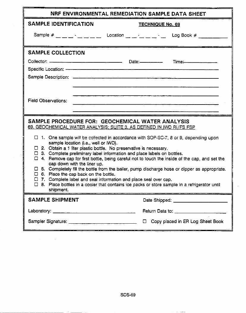
NRF ENVIRONMENTAL REMEDIATION SAMPLE DATA SHEET II SAMPLE IDENTIFICATION TECHNIQUE No. 69
Sample # - Location _ - --- ---- ----- - Log Book #
II II
SAMPLE COLLECTION Collector:
Specific Location:
Sample Description:
Date: Time:
Field Observations:
II SAMPLE PROCEDURE FOR: GEOCHEMICAL WATER ANALYSIS 69. GEOCHEMICAL WATER ANALYSIS: SUITE 3. AS DEFINED IN IWD RI/FS FSP
II q 1. One sample wi!l be co!lected in accordance with SOP-SC-i, 6 or 9, depending upon
sample location (i.e., well or IWD). 0 2. Obtain a 1 liter plastic bottle. No preservative is necessary. 0 3. Complete preliminary label information and place labels on bottles. 0 4. Remove cap for first bottle, being careful not to touch the inside of the cap, and set the
cap down with the liner up. 0 5. Completely fill the bottle from the bailer, pump discharge hose or dipper as appropriate. q 6. Place the cap back on the bottle. 0 7. Complete label and seal information and place seal over cap. 0 6. Place bottles in a cooler that contains ice packs or store sample in a refrigerator until
shioment.
II SAMPLE SHIPMENT Date Shipped:
/I Laboratory: Return Data to:
II Sampler Signature: Cl Copy placed in ER Log Sheet Book
SDS-69

THIS PAGE WAS INTENTIONALLY LEFT BUNK

EGAG IDAHO, INC. ENVIRONMENTAL RESTORATION PROGRAM
SAMPLE HANAGEHENT OFFICE
Prepared by: _ d.-
C. S. Watkin&fTechnical Leader, ERP SMO Date
Reviewed by: I ddy 14, f'79/
J. P. Chairman, ERP Independent Review Connnittee Date
D. J. Yut!mati'i Acting Manager, Data Management Unit

THIS PAGE WAS INTENTIONALLY LEFT BLANK

SOP No.: SMO-SOP-12.1.1 Page: 1 of 9 Date: 07/12/91
1. PURPOSE AND SCOPE
The purpose of this standard operating procedure (SOP) is to define the levels of method validation that will be used by the EG&G Idaho Environmental Restoration Program (ERP) Sample Management Office (SMO) and the firms under subcontract to the ERP SMO to perform method validation of chemical analysis data. These levels of method validation are for validating hazardous constituent chemical and radiological analytical data.

r-^ rnr -- GC -- IC? -- L&V --
MS -- PO -- QC __
SMO -- SOP --
SOP No.: SMO-SOP-12.1.1 Page : 2 of 9 Oate: 0,/12p L, ._
2. ACRONYMS/DEFINITIONS
invironmentai Restoration Program gas chromatograph(y) inductively coupled plasma i:iii:trtions and validation mass spectrometer(y) program directive
,,..I :+.. rr"+r^t qucl, I *J' CUllCl "I Sample Management Office standard operating procedure
Qata Qualifier Flaq: A label, usually in the form of one or more letters of the alphabet or some other symbol such as "t" or "*," that is used to document nnnrnnfnwmnrrac and/m limit.+innc with 2~ sna!ytjca: rs:u!t. Ths jafie .._.._-... I . . _ ..--- “., , “. . . . . ..“““.“..e “%.#I
letter(s) designates different attributes to the data depending on the analysis being validated.
Data Limitations and Validation (L&V) Reoort: A report written by an analytical chemist or other technical expert performing method validation. The report documents any deficiencies in the data identified during the data
validation process.

SOP No.: SMO-SOP-12.1.1 Page: 3 of 9 Date: 07/12/91
3. POLICY
This SOP aonliez to a]! analvces nwformwl under the subcontracts ..- -_. -rr. .-- -..-..9 --- r-. -.'.'--
written by the SMO. These subcontracts include, but are not limited to, the Basic Ordering Agreement for Organics Analyses, the Inorganic Master Task Agreement, and the Radiological Master Task Agreement. This SOP may also apply to data from subcontracts not written by the SMO, if the SMO requirements for the deliverables necessary to perform the specified level of validation are received with the data package. The SMO is not responsible for setting policy on what level of validation is required for each project. The procedures and requirements section of this SOP only addresses the procedure for that portion of the method validated at the level of validation specified by the project (when some percentage of the total data from a project is requested).
All method validation functions (for method validation levels A or 6) shall be performed by personnel that have been trained to the SMO SOPS for method validation by personnel having equivalent experience with the analytical methods and laboratory procedures as the personnel generating the data. For method validation levels C and X the personnel performing these functions shall be trained to the applicable Environmental Restoration Information System (ERIS) SOPS and/or Engineering Department, Statistics and Reliability Engineering Group, Data Applications Unit Operating Procedures.
All limitations and validation (L&V) reports generated during the validation process will be cross-checked for accuracy, reviewed, and initialed by another person familiar with the validation procedure used to produce the report.

SOP No.: SMO-SOP-12.1.1 Page: 4of9: Oate: 07/12/5;:.,,-
4. PROCEDURES AND REDUIREMENTS
Level X is for data that have never been reviewed in any fashion. This r.+^r...r.. 4 c rrrrr.raA for data +h*+ -..a .._.,a_ nl.nn.4 +n hs ma+h,rrA .r,lirls+nA b..o\r.Ju, J Ia I SaFI ..z" .IImC .a, c IlG.F1 p I YIII.Z” I” YS lllZIII”Y .VI IYo*cY,
but that are entered into the Environmental Restoration Information System (ERIS) (e.g., data collected for which the laboratory requirements for analvcic were Fiat cnarifie(! ny the dgcumentatiofi nf therp renlliromonte is fine ".."',"." "r"". . "~". "...".. --
available. This would also apply to data for which ~only results are availabl,? and for which no raw data exist).
Requester 1. Informs the SMO that there are some unvalidated data that are to be entered into the ERIS.
SMO 2. Informs the ERIS database administrator that there are unvalidated data to be,entered into the ERIS and advises the ERIS database administrator to discuss schedule and input requirements with the requester.
4.2 Level C Validation
Level C method validation ensures that the data have been checked so th.1: the value returned from the laboratory or field instrument is the value :'i; Zs input into the ERIS (i.e., transcription error checking). if 3 data
pa&age is received from a laboratory performing analyses under a SMO-Prepare. statement of work, and Level C method validation is requested, the data package will be checked for completeness and any deficiencies will be resolved

SOP No.: SMO-SOP-12.1.1 Page: 5 of 9 Date: 07/12/91
with the laboratory so that a Level A method validation will be possible in the future. The responsibility for these checks will be with the Integrated Environmental Data Manaaement Svstem IIEDMSl coordinator. In addition to the
data package completeness check and data entry into the ERIS, the following will be checked, at a minimum:
. Chain of custody
. Requested versus reported analyses
. Analysis holding times.
All of the procedures used for the data entry and automated method validation steps that are performed by the IEDMS personnel are described in the EG&G Idaho Data Applications Unit operating procedures. The product of Level C method validation is analytical results uploaded to the ERIS.
4.3 Level B Validation
Level B method validation includes all of the requirements for Level C method validation and will additionally require chemist review of the data for:
. Method blank criteria (e.g. contamination)
. Matrix spike/matrix spike duplicate recoveries/precision
. Duplicate sample precision
. Surrogate spike recoveries

SOP No.: SMO-SOP-1.2.:;~: Page: S of 9 Date: - - . - -
UI/IZ/YI -
. Laboratory control samples recoveries (radiological methods)
. Any other method-specific quality control (QC) criteria.
The re.viei; Of ,l.l- --*^..a., ..L.ll I,,,,* 111~_*51 1-1 alla.,, be done ii? aCCOrdaiXi2 ‘W+th the appropriate portions of the SMO SOP for the specific analysis being reviewed.
The nmr(,,r+ of &lel FI mn+lrn,i u.,i.-l.+inn ir y” “Y”.. I Y 111-1111” .“I I”....I”II I., a L&V rsnnr+ Aarrrikinn the I--p.“’ * YC.zLI ,Y”,y
deficiencies noted from review of the above-listed items. The L&V report contains two sections. The first section of the L&V report is addressed to the laboratory that performed the analvcic _. . _ . , - . " . The first section rnntainc a -",,"",*,"
detailed account of all deviations from the requirements of the analytical method and/or task-specific SOW used to produce the data being validated. Section I of the C&V report also contains discussions of any suaaerted --so----- corrective actions that EG&G Idaho feels the laboratory should take to provide EG&G Idaho with a defect-free deliverable in the future. The second section of the L&V report is written with the data user as the target audience. The
second section contains sample by sample descriptions of any deviations from the requirements of the analytical method used and/or other requirements specified in the SOW. The second section also contains limitations statements on data usability (e.g., unusable, estimated quantitation limit, etc.) The second section should include discussions about precision of field duplica?a results, field and trip blank contamination, and bias corrections (RCRA investigations only) as specified in Chapter 1 of SW-846, Revision 1, November 1990. The language used in Section 2 of the L&V report must be easily urderstood by a person with only a minimal background in analytical chemistry, The following is an example of a limitations statement:
"The analytical holding time of sample xxxxxx was exceeded by fifteen (15) days; therefore, all data for sample xxxxxx were flagged "R", meaning unusable for any purpose."

SOP No.: SMO SOP 12.1.1 Page: ; of-9 Date: 07/12/91
A required attachment to the L&V report wiii be a tabie (QC tabiej or a copy of the validated results forms (Form 1 for CLP type data, and radiochemical data produced under the EG&G Idaho ERP Radiological Master Task Agreementj to summarize aii anaiyticai resuits and the data quaiifier fiags associated with the results. The definitions of the data qualifier flags are found in the SMO SOPS that describe the specific data validation procedures , . (i.e., by anaiysis typej. -Lm '-I- -..-lf.?... e,.- >-e1_1L1._. .__ .,._ L_ tne oaca quablrler rlag O~TI~ILIV~S r;a.n d~so ue found in ERP Program Directive (PD) 5.8 "Control of Nonconforming Analytical Data." The flags on the QC table or Form 1 will be both those presented with IL- A-A_ L.. AL_ 3-L_-_L --.. --A LL^^^ -AA--I L.. l L^ -..,l.,.-l .*-,:.A-*l-- ,.I.-...: -c L"e "dL6 vy L,,r Ia""r~dL"r~y, *IL" LII">C a.uueu "J L,,C ulebll"" "a, I"~bl"II C11SIIII>L. The L&V report (with attachments) will be transmitted to the responsible project and waste area group (WAG) manager. All of the L&V reports and -AA--I---.- .~.A,, L^ ---I-A ..C +I.,. A.,,. lx,, oLL~.crltwllb~ 11111 us2 rupusu aid Shaii reSid2 With 211 Copies VI ~84s u.~*(L. tuvs original copies of the validated data package shall be returned to the ERP Administrative Record and Document Control Field Data Coordinator.
4.4 Level A Validation
Inuml A mcathnrl v.liAatinn ic thr, mav{gum effort fgr themjrij analvcic LF.Z, n ,,,C.,,,"Y .1#1".."1"11 8.f "I._ ".."..J-'-
method validation (i.e., complete review of the raw data for a given sample
analysis). As a minimum, additional to the requirements for Level B ICartinn A 7 nf this SOpj rnd C Ibrtinn 4.2 nf thic EoP) method Vaiidation. ,'s-.,'".' 7.w ". ,----.-.. .-- _.-..,
the following data will be reviewed:
. analyzis detection limits (radiological methods)
. Instrument calibration (both initial and continuing)
l Gas chromatograph/mass spectrometer (GC/MS) instrument performance criteria (tuning)
. Internal standards (organic GC and/or GC/MS methods)

SOP No.: SMO-SOP-12.I.J Page: 8 of 9 Qate: 07/12/91 1
. Laboratory control samples (LCS) (inorganic methods)
. Interference check samples (ICS) [inorganic inductively coupled plasma (ICP) and/or ICP/MS methods]
. Calculations and transcriptions from raw data to data reporting forms
. Mass spectral confirmation for positive results (organic GC/MS an; inorganic ICP/MS methods)
. Any other QC checks performed or required by the procedure or analysis
These checks will be done in accordance with the SMO SOP for the particular analysis being reviewed. All of the above-listed checks will be documented in the L&V report. The L&V report format (including required attachments) shall be as described. in Section 4.3 of this SOP.

SOP No.: SMO-SOP-12.1.1 Page: 9 of 9 Date: 07/12/91
5. NONCONFORMANCES
All nonconforming analytical data that are discovered during'the method validation process (method validation levels A and 8) will be documented in accordance with ERP PD 5.8, "Control of Nonconforming Analytical Data."

THIS PAGE WAS INTENTIONALLY LEFT SLAM

EGA6 IDAHO, INC. ENVIRONMENTAL RESTORATION PROGRAM
SAMPLE NAJMGENENT OFFICE
STANDARD OPERATING PROCEDURE NO. SMO-SOP-12.1.3
VALIDATION OF VOLATILE AND SENIVOLATILE ORGANIC GAS CHROMATOGRAPHY/MASS SPECTROMETRY DATA
For USEPA Methods MAIL n77ll L;9A 3 .n.-l PI D _- .-, VW. VI -..-..., “.._ --.

THIS PAGE WAS INTENTIONALLY LEFT RANK

EG&G IDAHO, INC. ENVIRONMENTAL RESTORATION PROGRAM
SAMPLE MANAGEMENT DFF!CE
STANDARD OPERATING PROCEDURE NO. SMO-SOP-12.1.3
VALIDATION OF VOLATILE AND SEMIVOlATILE ---__.-- -_- -..--.._----_-.... ..--- -------..--.. -.-. UKliANIC CiAS CHKUIWlUWAPHY/NASS SPCCTRONETRY DATA
Prepared by:
R. 0. Grant, Scientist, ERP SMD
Reviewed by:
Approved by:
(jjq*ll,
$WG, Date
d/4/4! Date
ii
,

1.
2.
3.
4.
5.
CONTENTS
PURPOSE AND SCOPE ...............................................
ACRONYMS/DEFINITIONS ...........................................
DESCRIPTION ....................................................
PRECAUTIONS AND LIMITATIONS ....................................
VOLATILES AND SEMIVOLATILES PROCEDURE ..........................
I. Holding Times ............................................
ii. ^^ ... . - w/m:, luning .............................................
III. Calibration ..............................................
IV. Blanks ...................................................
V. Surrogate Recovery .......................................
VI. Matrix Spike/Matrix Spike Duplicate ......................
VII. Field Duplicates .........................................
VIII. Internal Standards Performance ...........................
IX. Target Compound Identification ...........................
X. Compound Quantitation and Reported Detection Limits ......
X! . Tentatively Identifjed Compounds .................................
XII. System Performance .......................................
XIII. QC Check Samples For 524.2 ...............................
XIV. Overall Assessment of Data for an SDG ....................
cL0SSAP.v A: DATA QUALIFIER DEFINITIONS . . . . . . . . . . . . . . . . . . . . . . . . . . . . . .
1
1
2
3
3
4
5
7
10
13
14
15
15
16
17
18
I ?
21
21
22
iii

EG&G IDAHO, INC. ENVIRONMENTAL RESTORATION PROGRAM
SAMPLE MANAGEMENT OFFICE STANDARD OPERATING PROCEDURE
VALIDATION OF VOLATILE AND SEMIVOLATILE ORGANIC GAS CHROMATOGRAPHY/MASS SPECTROMETRY DATA
1. PURPDSE AND SCOPE
This document is a standard operating procedure (SOP) designed to offer guidance in the evaluation and validation of volatile and semivolatile organic gas chromatography/mass spectrometry (GC/MS) data.
The specific areas covered in this SOP include holding times, instrument performance, calibrations, blanks, surrogates, field duplicates, matrix spikes, compound identification, compound quantitation, reported dotectjn~ limit< . . "") 2nd final assessfiefit for the ramnlo delivery gro!~p ""...* . " (SDG).
2. ACRONYMS/DEFINITIONS
zip Contract iaboratory Procedure CDC Chain of Custody EPA Environmental Protection Agency ERP Environmental Restoration Program GC Gas Chromatography
::v Internal Standard Limitations and validation
MPD Matrix Spike Duplicate MS Mass Spectrometry MS ""A.":.. r":I*^ I'ldL,~IA z.p,nr NIST National Institute of Standards and Technology
.RIC Reconstructed Ion Chromatogram RPD Relative Percent Differences RQL Required Quantitation Limit RRF Relative Response Factor RRT Relative Retention Time RSD Relative Standard Deviation SDG Sample Delivery Group SHO Csmnln Y.n.na."nnn+ f-iCCir.3 +"vy'c "~,,yICV'F" "I t 0r.z SOP Standard Operating Procedure sow Statement of Work TCL Target Compound List TIC Tentatively Identified Compound VOA Volatile Organic Analysis voc Volatile Organic Compound BFB Bromofluorobenzene - volatile tuning compound BNA Base/neutral/acid compounds - compounds analyzed by
semivolatjle techniqge.
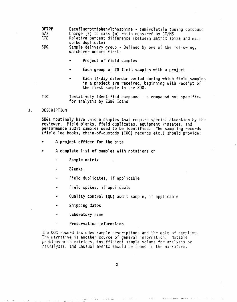
DFTPP m/z ;.22
SDG
Decafluorotriphenylphosphine - semivolatile tuning compounc Charge (z) to mass (m) ratio measured by GC/MS Relative percent difference (betwcs.1 .natt-ix spike and r!,:.: spike dupiicatej Sample delivery group - Defined by one of the following, whichever occurs first:
. Project of field samples
. Each group of 20 field samples with a project
. Each 14-day calendar period during which field samples -^-^ '..-A L--l--l__ _.ILL .____ 1-L _I in a project are I~CLCl"~") ucy I1811 I "y w I LII r-e--e I p L "I the first sample in the SDG.
TIC Tentatively identified compcund - a compound not specifieti for analysis by EG&G Idaho
3. DESCRIPTION
SDGs routinely have unique samples that require special attention by the rclvi ewnr Fialrl hl ,n!,c CinlA Allnlir~+ar .3no,inmnn+ r:nr,+,,r 3n.4 I ., I.W.1 . I I.,," "'"""1) # lZl" ""p'Ib~rs+, r~"!~11115 I IblJclbCJ) OllU performance audit samples need to be identified. The sampling records (field log books, chain-of-custody (COC) records etc.) should provide:
. A project officer for the site
. A complete list of samples with notations on
Sample matrix
Blanks
Field duplicates, if applicable r.~. I rielo spikes, if appiicabie
Quality control (QC) audit sample, if applicable
Shipping dates
Laboratory name
Preservation information.
The COC record includes sample descriptions and the date of sampling. T>,? narrative is another source of general information. Notable cr?blems with matrices, insufficient sample volume for analysis or r,iaoalysis, and unusual events shoulo bs found in the narratjve.
2

4. PRECAUTIONS AND LIMITATIONS
In order to use this SOP effectively, the reviewer should have experience in gas chromatography analyses and data review and a general o.<erviei+j of LL- Pl3" ___-.A Lll.2 2"". The exact number of sampies, sampie identification, and sample matrix are essential information. Background information on the site is helpful but is often difficult to obtain. The EG&G Idaho, Environmental Restoration Program (ERP) Sample Management Office (SMO) is the best source for background information on a specific sampling site (for ERP projects), answers, or further direction.
The most restrictive validation flag must always be assigned to the data ifi all instances where the data *--,mJ--- a TquI~ 52 qua1 ifiCatiO8 for iiiOE than One reason. For example, nondetect data that must be flagged as rejected "R" because of holding time violations and must also be qualified with. the quantitation flagged as estimated "UJ" must always be flagged as rejected "R".
5. VOLATILES AND SEMIVOLATILES PROCEDURE
The following are the requirements (listed by section) to be checked for vaijdatjon:
I. Holding Times
II. GC/MS Tuning
1~1 I. Calibration
. Initial
. Continuing
IV. Blanks
v . surrogate Recovei-y
VI. Matrix Spike/Matrix Spike Duplicate (MS/MPD)
VII. Field Duplicate
VIII. Internal Standards Performance
IX. Target Compound Identification (TIC)
X. Compound Quantitation and Reported Detection Limits
XI. Tentatively Identified Compounds (TIC)
XII. System Performance
3

XIII. QC Check Samples For 524.2
XIII. Overall Assessment of Data for an SDG
,‘,“” ,,-,,,,,,, ~ !~
I. HOLDING TIMES
A. Criteria
'T~~,~~~G Idaho ERP SMO requirements for sample holding times are as
All Puraeables:
Unpreserved aromatic volatiles must be analyzed within 7 days and nonaromatic volatiles must be analyzed within 14 days from the time of collection. Aromatic and nonaromatic volatiles must be anilV7n~ Wi?hil! !4 days from the ti.me of camnlrr co!iectio!! if t!!e _. . _ , - - - _-... r - samples were preserved with hydrochloric acid and stored at 4°C.
Btractables: - ._ 501 isjsedimentsjsiudges: --- Ali sampies must be extracted within 14 days of sample collection. Extracts must be analyzed within 40 days of sample extraction. Samples and extracts must always be stored at,,,AK.
Water: All samples must be extracted within 7 days of sample ' collection. Extracts must be analyzed within 40 days of sample
extraction. Samples and extracts must always be stored at 4-C.
8. r ___.___ A>_- ..-_-_A__-_ cva I "iAL I",, rr"~e""re
Establish holding times by comparing the sample collection date'on the EG&G Idaho COC form with the dates of extraction and analysis on Form I. Examine the sample records (COC form, field logbooks, etc.) to determ::.e if samples were properly preserved. The samples must be presumed unpreserved if no indication of preservation is stated in the samplirrj documentation.
c. Actfon
1. If holding times are exceeded:
Flag all positive results as estimated quantities (J) and compov-:i quantitation limits as estimated (UJ). State in the limitations and validation (L&V) report that holding times were exceeded.
2. if holding times are exceeded by more than double the ailo'ti?.bl:? 'rnl,i<-r t'mo. ,.v,_ .,z "..,._.

Flag non-detect data as unusable for any purpose (R) and flag all positive results as estimated quantities (J). State in the limitations and validation (L&V) report that holding times were exceeded.
II. GC/MS TUNING
. et. iwierir
SEMIVOLATILE;
1.
VOLATILE:
2.
Decafluorotriphenylphosphine (DFTPP)
il!Lz Ion Abundance Criteria
51 30.0 to 60.0% of m/z 198 68 Le:: than 2.0% of m/z 69 70 Less than 2.0% of m/z 69
127 40.0 to 60.0% of m/z 198 197 Less than 1.0% of m/z 198 198 Base peak, 100% relative abundance 199 5.0 to 9.0% of m/z 198 275 10.0 to 30.0% of m/z 198 365 Greater than 1.00% of m/z 198 441 Present, but less than m/z 443 442 Greater than 40.0% of m/!/z 198 443 17.0 to 23.0% of m/z 442
gromofiuorobenzene (BFB)
!l!Lz Ion Abundance Criteria
50 15.0 to 40.0% of the base peak 75 30.0 to 60.0% of the base peak 95 Base peak, 100% relative abundance 96 5.0 to 9.0% of the base peak
173 Less than 2.0% of m/z 174 .-.I 114 Greater than jir.iix of the base peak 175 5.0 to 9.0% of m/z 174 176 Greater than 95.0%, but less than 101.0% of m/z 174 177 5.0 to 9.0% of m/z 176

YOLATILF, Method 524.2;
& Jon Abundance Criteria
50 15.0 to 40.0% of the base peak 75 30.0 to 80.0% of the base peak 95 Base peak, 100% relative abundance 96 5.0 to 9.0% of the base peak
173 Less than 2.0% of m/z 174 174 Greater than 50.0% of the base peak 175 5.0 to 9.0% of m/z 174 1;: Greater than 95.0X, but less than 101.0% of m/z 174 _. . 5.0 to o*o% of mh 1?6
8. Evaluation Procedure
1. Verify from the raw data that the mass calibration is correct.
2. Compare the data presented on each GC/MS tuning and mass calibration (Form V) with each mass listing submitted.
3. Ensure the following:
a. Form V is present for eqch 12-hour period that samples are anal yred.
be TL- I-L---L--.. L-- -^c -...I” _“.. 4.” . ...*- . ..4...,“.. ...“lnrC ,nr I~““r-a.r”r;r ,,a> ,,“I. ,,,a”t WIJ l,ial,JCl ,p”“” 511”I a. /
C. The appropriate number of significant figures has been reported (number of significant figures given for each ion in the ion abundance criteria column).
d. The laboratory has not made any calculation errors. For example, the percent mass of m/z 443 relative to the mass of m/z 442 is calculated using the following equation:
% abundance a relative ab ndance of m/z 443 x 100 relative abindance of m/z 442
4. If possible, verify that spectra were generated using appropriate background subtraction techniques. Background subtractlon shouid be straightforward and designed only to eliminate column bleed or instrument background ions. Background subtraction actions resulting in spectral distortions for the sole purpose of meetin; tho rnntrart cnnrifjr;tjms are gntrwy to t_hp qmlity ass~!ra:,i:c “a.” ..“..V. m-v -v-w.. objectives and are, therefore, unacceptable.
,, mars CaliDratlon is in error, ciassify aii asscciatad dais iil I .,Y ;.:4.:L’;e (R).
6

c
III. CALIBRATION
A. Criteria
i. initiai Caiibration
a. Volatile and Semivolatile Fractions
1) All average relative response factors (RRF) for target compound list (TCL) analytes must be ~0.05.
2) All percent relative standard deviations (ZRSD) must be 530% (~20% for 524.2).
2. Continuing Calibration
a. Volatile and Semivolatile Fractions
1) All RRFs for TCL analytes must be 10.05.
2) All percent differences (0%) must be ~25% (~30% for 524.2).
B. Evaluation Procedure
1. Initial Calibration
a. Evaluate the RRF and RRF for all target compounds and verify the following:
1) Check and recalculate the RRF and RRF for one or more volatile 2nd se.qjvolatjie target rnmnntlnd<. --"'r--"-- 7 verify that the recalculated value(s) agree with the laboratory reported value(s) (Form VI).
2) Verify that allvolatile and semivolatile target _ __ compounds have KKr of at ieast u.u5.
b. Evaluate the percent Relative Standard Deviation (%RSD) for all target compounds and verify the following:
1) Check and recalculate the %RSD for one or more target compounds; verify that the'recalculated value agrees with the laboratory reported value, The %RSD is calculated using equations (2) and (3).
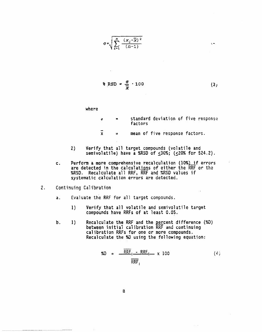
(31
where
0 = standard deviation of five response factors
; = mean of five response factors.
2) Verify that all target compounds (volatile and semivolatile) have a %RSD of 130%; (120% for 524.2).
C. Perform a more comprehensive recalculation (lO%uf errors are detected in the calculations of either the RRF or the XRSD. Recalculate all RRF, RRF and %RSD values if systematic calculation errors are detected.
2. Continuing Calibration
a. Evaluate the RRF for all target compounds.
1) Verify that all volatile and semivolatile target compounds have RRFs of at least 0.05.
b. 1) Recalculate the RRF and the mcent difference (%D) beiween initial Calibration RRi and continuing
calibration RRFs for one or more compounds. Recalculate the XD using the following equation:
- %D = RRF,AfmRRF,- x 100 (4;
RRF,
8

where
RRF, =. average RRF from initial calibration.
RRF, = RRF from continuing calibration standard.
2) Verify that the percent difference is $25%, (130% for __. _. - 524.2) for aii voiatiie and semivoiatiie target compounds.
C. Perform a more comprehensive recalculation (10%) if errors are detected. Recalculate all RRF and percent difference values if systematic calculation errors are encountered.
C. Acti on L.TIL~.-LI.. i. iniiiai L~IID~~LIO~
a. Ifany volatile or semivolatile RRF of less than 0.05:
target compound result has a
1) Flag positive results for (J).
that compound as estimated
2) Flag non-detects for that compound as unusable (R).
target compound has a %RSD . -. b. If any volatile or semivolatile of greater than 30% (20% for 524.2):
1) Flag positive results for that compound as estimated (J).
2) Qualify non-detects with the quantitation limit flagged as estimated (UJ) if:
60% J %RSD J 90%
40% s %RSD J 80% for 524.2.
3j Fiag non-detects as unusabie (Rj if:
XRSD > 90%
%RSD > 80% for 524.2.
9

2. Continuing Calibration
a. If any volatile or semivolatile targ?! compound has a I?"F less than 0.05:
1) Flag positive results for that compound as estimate3 (J).
2) Flag non-detects for that compound as unusable (Rj.
b. If any volatile or semivolatile target compound has a percent difference between initial and continuing --..1~ AL* caiiorarion of greater than iS% (30% for 524.23:
1) Flag all positive results for that compound as estimated (J).
2) Qualify non-detects with the quantitation limit flagged as estimated (UJ) if:
CnOI * 0," J"lo 3 /aI i 75%
60% 1: %D i; 90% for 524.2.
3) Flag non-detects as unusable (Rj if:
Ya) > 75%
Y! > 90% for 524.2.
IV. BLANKS
A. Criteria
No contaminants should be present in the blank(s).
B. Evaluation Procedure
1. Review the results of all associated blank(s), Form I(s), and raw data (chromatograms, reconstructed ion chromatograms, quantitation reports, or data system printouts). ,
2. Verify that method blank analysis has been reported per matrix, per concentration level, for each GC/MS system used to analyze volatile organic analysis (VOA) samples, and for each extracti.?: batch f3r semivolatiles. The reviewer Can use the method blai-I: z~nnmzarv fFnrm TV\ t.0 a:sjsc in identifvinn _ _ - , \ _ _ , - - - , = zimn1oc a$sQcjat&ad g;ti> _-... r _- each method blank.
10

C. Action
Action in the case of unsuitable blank results depends on the rirrlllnrt.nr~r lnrl nrinin of the blank. ..VI -"II.,".d..Q-., ..a." -. .x... No nncitive camnle rerujts should be reported unless the concentration'of'the-c~~~~~~d in the sample exceeds 10 times the amount in any blank for the common contaminants listed below, or 5 times the amount for other compounds. In instances where more than one blank is associated with a given sampie, quaiification shouid be based on a comparison with the associated blank having the highest concentration of a contaminant. The results must not be corrected by subtracting any blank value, actions are as follows:
Specific
1. No action Is taken if a compound is found in a blank but not found in the sample.
2. Any compound (other than the five listed below) detected in the sampie ano also detected in any associated blank must be qualified when the sample concentration is less than five times the blank concentration. Analvtical limit of detection when the samole concentration is less than 10 times the blankconcentration for the followinq five comoounds:
Common lab contaminants:
. Methylene chloride Acetone
. Toluene
. 2-butanone
. Common phthalate esters
The reviewer should note that the blank analyses may not invoive the same weights, volumes, or dilution factors as the associated samples. Sample weights, volumes, and dilutions must be taken into consideration when applying the 5x and 10x criteria, so that 2 COmpariSOR Of the tOta! %l!OU!?t Of contamination is aCtUai!y made.
There may be instances where little or no contamination was present in the associated blanks but qualification of the sample was deemed necessary. Contamination introduced through diiution solvent is one example. Instances of contamination introduced through dilution solvent can be detected when contaminants are found in the diluted sample result but are absent in the undiluted samale result, The sample value should be reoorted as a non- --.-r - detect if the reviewer determines that contam\nation is from a source other than the sample. The 5x or 10x rule does not apply in cases of contamination from a source other than the sample where the contamination is not reflected in the associated blank.
11

3. The following are examples of applying the blank qualification guidelines.
Case I: The sample result is greater than the required quantitation limit (RQL) but is less than the requiri:;1 amount (5x or 10x) from the blank result.
Rule
Blank result 7 7 RQL 5 5 Sampie resuit Qualified sample result 6;: 3::
In the example for the 10x rule, sample results <70 (or IQ x 7) would be qualified as non-detects. In the case of the 5x rule, sample results ~35 (or 5 x 7) would be qualified as non-detects.
Case 2: Sample result is less than the RQL and is also less than the required amount (5x or Xxj from the biank result.
Rule
J& 5x
Blank result 6 RQL 5 2 c-...^, ^ r^r.*l + 4awp, c I S2" I c ?J 4J Qualified sample result 5U 5U
Case 3. -- Sample result is greater than the required amount (5x or 10x) from the blank result.
Rule
Blank result 10 10
RQL 5 Sample result 120 6: Qualified sample result 120 60
Sample results exceed the adjusted blank results of 100 (or 10 x 10) and 50 (or 5 x lo), for both the 1'9~ and 5x rules, resoectively.
12

4. All compounds affected should be flagged as unusable (R), due to interference, in all samples affected if gross contamination exists (e.g., saturated peaks by GC/MS).
v. SURROGATE RECOVERY
A. Criteria
bmnle and blank strrroaate rernwriec for vnlatilpc and cemivnlatilac i _... r__ -..- _.- __. -a--- _ _ _ _ _ _ _ ._.-_..-_ -..- _- ,...._, - _.,__ must be within the limits specified in the analytical method or applicable statement of work (SOW) (Form II).
8. Evaluation Procedure
1. Check the raw data (e.g., chromatograms, quantitation list, etc.) to verify the recoveries on the surrogate recovery form (Form II).
2. The following should be determined from the surrogate recovery form(s):
a. If any two surrogates within a base/neutral or acid fraction (or one surrogate for the VOA fraction) are out of --^^IcI--+I-.. ,~=~,,, ,~~~,",,, or :c --.. ^_^ L -..-I--.. L--7 I I a,,J "11s "a>s,llsucr a,, acid, or VOA surrogate has a recovery of <lo%, the sample(s) should be reanalyzed.
b. The laboratory has failed to perform satisfactorily if surrogate recoveries are out of specification with no
'evidence of repurging, reinjection, or reextraction.
C. Verify that no blanks have surrogates outside the recovery rri+ari 3 _I IUSI IV.
3. Validate and report all analyses any time there are two or more analyses for a particular fraction.
C. Action
The following approaches are suggested based on a review of all data from the SDG for surrogate spike recoveries out of specification.
1. If at least two surrogates in a base/neutral or acid fraction or one surrogate in the volatile fraction are out of specification, but have recoveries >lO%:
a. Positive resuits for that fraction are ~fiagged as estimated (J).
b. Negative results for * that fraction are qualified with the sample quantitation limit flagged as estimated (UJj.
13

2. If any surrogate in a fraction shows less than 10% recovery:
a. Positive results for that fraction are flagged as estima:.-:! (J).
b. Negative results for that fraction are flagged as unusable (RI.
3. Ia the Special Case Of a blank ana!ySiS With SUrrOgrteS OUt Of specification, the reviewer must give special consideration to tne validity of associated sample data. The basic concern is whether the blank problems represent an isolated problem with the blank alone or whether there is a fundamental problem with the _---___ anaiytical pwwas. r___ _.._ --1_ I-",. endwplr, if one or more sampies in the batch show acceptable surrogate recoveries, the reviewer may choose to consider the blank problem an isolated occurrence.
VI. MATRIX SPIKE/MATRIX-SPIKE DUPLICATE
A. Criteria
1. Spike recoveries must be within the advisory limits established in l t.- .m..rr....: Cllr o~p~vvm ,ate 6i;aiytiCal itidiGd Or appliC.&ie SOW iioim iiij.
2. The relative percent differences (RPD) between MS/MSD recoveries must be within the advisory limits established in the appropriate analytical method or applicable SOW (Form III).
.B. Evaluation Procedure ,
1. Inspect the results for the MS/MS0 recovery (Form III).
2. Verify the transcriptions from the raw data and verify the calculations.
C. Action
No action is taken on MS/MSD data alone to qualify an entire SDG. However the data reviewer may use the MS/MSD results in conjunction with &F;r QC criteria and determine the need for some qualification of the
The data reviewer should first try to determine to what extent the results of the MS/MS0 affect the associated data. This determination should be made with regard to the MS/MSD sample itself, as well as . . - . . . - - specific analytes for aii sampies associated with the mymbu. Aii qualification of data based on MS/MSD results should be documented in detail in the L&V report.
14

VII. FIELD DUPLICATES
8. Evaluation Procedures
Field duplicates shouid be identified using EG&G idaho COC forms or sample field logbooks. The reviewer should compare the positive resul'ts reported for each sample and calculate the RPD. The final L&V report should mention incidences of one sample of a duplicate pair having a positive result and the other sample of the duplicate pair having non- detect results (whether due to different dilution or not).
C. Action
n ̂ _^- c LL- nn.7 L-L ..--- Cl-72 1-,1--L-. LL. .-! ~~. ~r)ror~b ~nr nrv or~wrrn rcelu uup~~ra~es in me rinal report. Evaiuation of the field duplicate data will be made by the appropriate EG&G Idaho ERP project management personnel.
VIII. INTERNAL STABMJAROS PERFORMANCE
A. Criteria
1. Internal standard (IS) area counts must not vary by more than a factor Of two rLrn +a \-4" I," tlDO%) from the associated continuing calibration standard.
2. The retention time of the IS must not vary more than +30 seconds from the associated calibration standard.
B. Evaluation Procedure
1. Check the raw data (e.g., chromatograms, quantitation lists) to varifv ?hr, recpJ$ries rnnnrtmi g,q the ints3b.n.1 r+.nr(.rrl =.-LI= _-. . ., , -r". --- 111"-1 ,,"a -*Yll"Yl" "I ZY summary (Form VIIIA, VIIIB).
2. Verify that all retention times and IS areas are acceptable.
3. The reviewer wiii vaiidate and report &J, analyses any time there are two or more analyses for a particular fraction.
c. Action
1. If an IS area count is outside -50% or t lOO% of the associated standard,
a. Flag positive results for compounds quantitated using that iS as,estimated (Jj for that sampie fraction.
15

b. Flag non-detects for compounds quantitated using that IS with the sample quantitation limit classified as estimaW (UJ) for that sample fraction.
C. Flag positive results as estimated quantities (J) and flag non-detect results as unusable (R) if area counts are below 25%.
2. The chromatographic profiie for a given sampie must be examined Lo determine if any false positives or false negatives exist if an IS retention time varies by more than 30 seconds. All data associated with an IS having a retention time shift of greater than f 1 minute must be flagged as unulahie !R)l
IX. TARGET COMPOUND IDENTIFICATION
A. Criteria
1. The compound must be within +0.06 relative retention time (RRT) units of the standard RRT.
2. Mass spectra of the sample compound and a current laboratory- generated standard must match according to the following criteria:
a. All ions present in the standard mass spectrum at a relative intensity >lO% must be present in the sample spectrum.
b. The relative intensities of ions specified above must agree within 220% of the standard and sample spectra. (Example: For an ion with an abundance of 50% in the standard spectrum, the corresponding sample ion abundance must be between 30% and 70%.)
C. Ions greater than 10% in the sample spectrum, but not present in the standard spectrum, must be considered and accounted for.
a. Evaluation Procedure
1. Check that the RRT of reported compounds is within 0.06 RRT units of the reference standard.
2. Check the laboratory standard spectra versus the sample compound spectra.
3. The reviewer should be aware of situations (e.g., high concentration samples preceding low concentration samples) rh(:n sample carryover is a possibility and should use judgment to determine if instrument cross-contamination has affei:zd an): positive ;umyouno identification.
16

C. Action
1. Flag all such data as not detected (U) if the reviewer determines that incorrect identifications were made.
2. All cases of suspected cross-contamination must be discussed in the L&V report.
X. COMPOUND OUANTTTATION AND REPORTED DETECT!ON LIMITS
A. Criteria
1. _L1A-I1-- COmpoiiiid qiM.nLlraclon, as weii as the adjustment of the RQL, must be calculated according to the analytical method or appropriate sow.
2. Compound RRF values must be calculated based on the IS specified in the analytical method or applicable SOW. Quantitation must be based on the quantitation ion (m/z) specified in the analytical method. The compound quantitation must be based on the RRF from the appropriate daily standard (continuing calibration standard).
6. Evaluation Procedure
1. All raw data should be examined to check the calculation of all sample results reported by the laboratory. Quantitation lists, chromatograms, and sample preparation logsheets should be compared to the reported positive sample results and quantitation limits (Form 1).
7 -. Vnrifv thrt the cnyect intamal Standard .-. .., .,."*, .,". n,,>n+i+.+inn ion, 2nd ..,,"", ", '("""I .,Y., l"ll RRF were used to quantitate the compound.
3. Verify that the RQLs have been adjusted to reflect all sample dilutions, concentrations, splits, cleanup activities, and dry-weight factors that are not accounted for by the method.
C. Action
The analytical laboratory may be contacted by the reviewer to obtain information that could resolve any discrepancies. The reviewer must flag the data associated with a particular discrepancy as unusable (R) if the discrepancy remains unresolved.
17

XI. TENTATIVELY IDENTIFIED COMPOUNDS
8 . Criteria
1. The laboratory must conduct a mass spectral search of the National Institute of Standards and Technology (NIST) library and report the possible identity for the 10 largest VOC fraction peaks and the 20 largest base/neutral/acid (BNA) fraction peaks that are not surrogates, IS, or TCL compounds, but which have an area/height greater than 10% of the nearest IS. Tentatively Identified Compound (TIC) results are reported for each sample on the organic analyses data sheet (Form I, TIC).
2. Guidelines for tentative identification are as follows:
a. Major ions (>lO% relative intensity) in the reference spectrum should be present in the sample spectrum.
b. The relative intensities of the major ions should agree within +20% of the sample and the reference spectra.
C. Molecular ions present in the reference spectrum should be present in the sample spectrum.
d. Ions present in the sample spectrum but not present in the reference spectrum should be reviewed for possible I.-^,* _I^.._ -I ^^-A--:..-&<^- "cl.\rhyl VU,," C"llC.mIIIIQL.I"1I, interference, or coelution of additional TIC or target compounds.
e. The reviewer will flag the TIC "unknown“ when the above criteria are not met.
B. Evaluation Procedure
1. Check the raw data to verify that the laboratory has generated a 1ihr.w.v cn.rrh Cnr 81; ran,,ird nn.!,r in the chramatograms ,111 Y’, 2C.A. _.I I”, I zy(Y a I FY pz..“’ (samples and blanks).
2. Blank chromatograms should be examined to verify that TIC peaks present in the samples are not found in the blanks. A thorough check of blank chromatograms may require looking for peaks that are less than 10% of the internal standard height but are present in the blanK chromatogram at a similar RRT when a low-level non- target compound that is a common artifact or laboratory contaminant is detected jfi a capll!a r'--
3. All mass spectra in every sample and blank must be examined.
4. All reasonable choices must be considered since TIC library searches often yieid several candidate compounds having a clilseij matching spectrum.
18 i

5. Common laboratory artifacts/contaminants and their sources (aldol products, solvent preservatives/reagent contaminants, etc.) may be present in blanks and not reported as sample TICS.
Examples:
a. Common lab contaminants: COs (m/e 44), siloxanes (me/e 73), diethyl ether, hexane, certain freons (1,1,2-trichloro- 1 .l * A-J,?7 ..--__ AL_-_ _- z,.._.__ L._I_L7-..---*L---\ I,‘,‘-Lr-lI I”u,-ut!LItd,le vr- I I”“,-“-Lr,1;,,1”r”III~:LllanB,, phthalates at levels less than 100 pg/l or 4000 pg/kg.
b. Solvent preservatives: Cyclohexene is a methylene chloride preservative. Related by-products include cyclohexanone, cyclohexenone, cyclohexanol, cyclohexenol, chlorocyclohexene, and chlorocyclohexanol.
C. Aldol reaction products of acetone include rl-hydroxy- "~-n~L,,l~,~-rlC.lrln " ".n+t.l.l 9 ..A..,^" 9 ^^^ 7-"'5*IIJ I -r-pS"*a"'""S, ~-Illsc,'J # -r-p,sl,r,sr,-r-u,,s, and 5,5-dimethyl-2(5H)-furanone.
6. Occasionally, a target compound may be identified in the proper analytical fraction by nontarget library search procedures even though it was not found on the quantitation list. If the total area quantitation method was used, the reviewer should request that the laboratory recalculate the result using the proper quantitation ion. In addition, the reviewer should evaluate other camnln rhmmatnnramc ad r-ha-k lihrrerv rafovanra ratantinn timnc - “...r . - “... ‘...-‘“a. “..... “..” .,,.--.. I .I. “0, I “._I “.I”” I -1..11.1111 “1111*- on quantitation lists to determine whether the false negative result is an isolated occurrence or whether data from the entire SDG may be affected.
7. --. ILL compounds may be identified in more than one fraction. Vet-i fy that quantitation is made from the proper fraction. .
C. Action
1. All TIC results should be flagged as tentatively identified with estimated concentrations (JN).
2. General actions related to the review of TIC results are as Pi.. TOI lows:
a. If it is determined that a tentative identification of a non-target compound is not acceptable, the tentative identification should be changed to "unknown" or an appropriate identification.
b. If all required peaks were not library searched, the reviewer should request these data from the laboratory.
19

3.
4.
5.
TIC results that are not sufficiently above the level in the blank should not be reported. (Dilutions and sample size must be taken into account when comparing the amounts present in blanks and samples.)
When a compound is not found in any blanks but is a suspected artifact or common laboratory contaminant, the result must be flagged as unusable (R).
Other case factors may influence TIC judgments. If a sample TIC match is poor but other samples have a TIC with a good library match, similar RRT, and the same ions, identification information may be inferred from the other sample TIC results.
XII. SYSTEM PERFORMANCE
During the period following instrument performance QC checks (e.g., blanks, tuning, calibr$ion), changes may occur in the system that degrade the quality of the data. whiie this degradation wouid not be directly shown by QC checks until the next required series of analytical QC runs, a thorough review of t?? ongoing data acquisition can yield indicators of instrument performance.
Some ourmolas of instrument nerformance inflicatnrz for var$ous fa_&rs are as -~~---I- -- ..-_. _... -.._ r__ _. ..- ..__ ..-._-__. _ follows:
1. Abrupt, drscrete shifts in reconstructed ion chromatogram.(RIC) ' basel.ine may indicate gain or threshold changes.
2. Poor chromatograptiic performance affects both qualitative and "' T;:;;;fative results. Indications of substandard performance
a. High RIC background levels or shifts in absolute retention times of IS
b. Excessive baseline rise at elevated temperature
C. Extraneous peaks
d. Loss qf resolution as suggested by factors such as nonresolution of 2,4- and 2,5-dinitrotoluene
e. Peak tallinq or peak splitting may result in inaccurate quantitation.
rnn+im,arl ans1\,+4,..1 .r+i,ri+v wi,k Aanr.,bA nbrCs.rm.nra .4mna.+c lnrlr nf *"It.III"FY P"",.nwe. 'W"'.'"J ","I. Y'y('qYcY y" /Y.I.IYII~~ '"yyL*s' II.R VI attention or professional experience. Based on the instrument performance indicators, the data reviewer must decide if the system has degraded to the goint of affecting data quality or validity. If data quality may have besn ;T:‘?cted. data should be qualified as estimated (UJ).
20
,,,,,,,,,,,,,,,,,,,,,,,,,,,,,,,,,,,,,,, ,.,,,,,,

XIII. .QC CHECK SAMPLES FOR 524.2
No qualification of data shall be made on the basis of QC check samples. Percent recovery values outside the 80 to 120% criteria required by the method shall be mentioned in the L&V report to EG&G Idaho.
XIV. OVERALL ASSESSMENT OF DATA FOR AN SDG
1c i.. ...mrr..ud.+^ c..,. +L.r .A..+,. ..r,,irL,nr +n n3L,, n".mC,Tr.-ir..~, i,,rlnmr\n+r 3n.i ,L I> a.)Ip,up, IOLS I", 4,115 "GIlrGI 15" 151151 8," IllQhS p, ",5.a~,"IIcAI Juuylllrll~a rn,I" express concerns and comments on the validity of the overall data package. The overall assessment is particularly appropriate for SDGs in which there are several QC criteria out of specification. The additive nature of QC factors out of specification is difficult to assess in an objective manner, but the reviewer has a responsibility to inform users concerning data quality and data limitations in order to assist the user in avoiding inappropriate use of the data while not precluding any consideration of the data at all.
21

GLOSSARY A
DATA QUALIFIER DEFINITIONS
For the purposes of this document, the following code letters and associated definitions are provided:
u - The material was analyzed for but was not detected. The associated numerical value is the sample quantitation limit.
J - The analyte was positively identified in the sample, but the associated numericai vaiue may not be an accurate representation of the amount actually present in the environmental sample. The data should be seriously considered for decision making and are usable for many purposes.
A subscript may be added to the ‘J” flag to indicate which of the following QC criteria were not met:
Jz Calibration range exceeded: indicates possible low bias.
J3 t$iding times not met: indicates results are biased
R - The data are unusable (may or may not be present). Resampling and reanalysis is necessary for verification.
N - Presumptive evidence of the presence of the material.
,NJ - Presumptive evidence of the presence of the material at an &ima_ted_ artantitv. 7--..-. -.s
UJ - The material was analyzed for but was not detected. The sample quantitation limit is an estimated quantity.
The reviewer must expiain and thoroughiy document the use of any quaiifiers -t+r than the ones listed above.
22