
Reliability Synthesis for UAV Flight Control Systemceur-ws.org/Vol-1844/10000569.pdf · Reliability...
14
Reliability Synthesis for UAV Flight Control System Yuriy Pashchuk 1 , Yuriy Salnyk 1 , Serhiy Volochiy 2 1 National Army Academy, 32 Heroes of Maidan street, Lviv, Ukraine, 79012 ([email protected], [email protected]) 2 National University Lviv Polytechnic, Lviv, Ukraine ([email protected]) Abstract. This paper presents the models and methods for reliability synthesis for components of UAV flight control system: flight computer and navigation system. The developed reliability models depict different variants of fault- tolerant designs including designes for systems with complex reliability behavior. They have a high level of adequacy, since effectiveness of detection and switching devices was taken into account. Based on the models, we proposed the reliability synthesis methods for flight control system components that allows making reasonable design decisions. As an example of using these methods, the reliability requirements and recommendations for rational choice of fault-tolerant designs were developed to meet required reliability level of UAV flight computer and navigation system. Keywords. Unmanned aerial vehicle (UAV), flight computer, navigation system, flight control system, reliability model of fault-tolerant system. Key Terms. Model, Mathematical Modeling, Markov model. 1 Introduction Although UAV’s reliability has significantly increased for the last 15 years, this problem is still among the focus issues for manufactures and different branches of military [1-5]. The current UAV’s failure and accident/mishap rates are much higher than that of manned air platforms. Approximately a quarter of all UAV’s failures are caused by flight control system (FCS) failures [1-4]. This system contains three main components (Fig. 1) [1-3]: navigation system (NS), flight computer (FC) and autopilot (AP). All these components are failure-critical. In this paper, we choose NS and FC as research objects due to their complex reliability behavior. Based on the analysis of reliability measures and characteristics [1-5], the least reliable FC parts are microprocessors and the least reliable NS parts are gyroscopes and accelerometers.
Transcript of Reliability Synthesis for UAV Flight Control Systemceur-ws.org/Vol-1844/10000569.pdf · Reliability...

Reliability Synthesis for UAV Flight Control System
Yuriy Pashchuk1, Yuriy Salnyk1, Serhiy Volochiy2
1National Army Academy, 32 Heroes of Maidan street, Lviv, Ukraine, 79012
([email protected], [email protected]) 2National University Lviv Polytechnic, Lviv, Ukraine
Abstract. This paper presents the models and methods for reliability synthesis
for components of UAV flight control system: flight computer and navigation
system. The developed reliability models depict different variants of fault-
tolerant designs including designes for systems with complex reliability
behavior. They have a high level of adequacy, since effectiveness of detection
and switching devices was taken into account.
Based on the models, we proposed the reliability synthesis methods for flight
control system components that allows making reasonable design decisions.
As an example of using these methods, the reliability requirements and
recommendations for rational choice of fault-tolerant designs were developed to
meet required reliability level of UAV flight computer and navigation system.
Keywords. Unmanned aerial vehicle (UAV), flight computer, navigation
system, flight control system, reliability model of fault-tolerant system.
Key Terms. Model, Mathematical Modeling, Markov model.
1 Introduction
Although UAV’s reliability has significantly increased for the last 15 years, this
problem is still among the focus issues for manufactures and different branches of
military [1-5]. The current UAV’s failure and accident/mishap rates are much higher
than that of manned air platforms. Approximately a quarter of all UAV’s failures are
caused by flight control system (FCS) failures [1-4]. This system contains three main
components (Fig. 1) [1-3]: navigation system (NS), flight computer (FC) and
autopilot (AP). All these components are failure-critical. In this paper, we choose NS
and FC as research objects due to their complex reliability behavior. Based on the
analysis of reliability measures and characteristics [1-5], the least reliable FC parts are
microprocessors and the least reliable NS parts are gyroscopes and accelerometers.

Autopilot
Navigation system
Flight computer
Microprocessor MP 1
Onboard GPS
Radio command equipment
Magnetometer
(MM)
Kalman filter
( KF - 1 )
Pressure and temperature transdusers
Pitot tube
Air data subsystem (ADS)
(ADS)
Г іроскоп 1
Г іроскоп 2
Гіроскоп По осі Z
Gyroscope G X
Gyroscope G Y
Gyroscope G Z
Accelerometer A X
Accelerometer A Y
Accelerometer A Z Inertial measurement unit
(IMU)
Microprocessor MP 2
Microprocessor MP 3
Microprocessor MP R
Voting unit
Fault detector
Kalman filter ( KF - 2 )
Control Unit
Payload
Power / propulsion
Flight control surfaces
Telemetry and
data radio
Servo units
Power / propulsion controller
GСS
Ground control station (GСS)
Fig. 1. UAV flight control system architecture
The researches, aimed to increase FCS reliability on the design stage, are important.
It concerns reliability synthesis for navigation system and flight computer, namely,
reasonable choice of their reliability parameters and fault-tolerant configurations to
meet required reliability level. There are two major approaches for solving these
issues [2-9]: fault avoidance with improvement of failure-critical subcomponents
reliability, and fault tolerance based on redundancy with use of effective detection and
switching devices (DSD). The second approach is used extensively for improving
reliability of military UAVs [2-10]. For instance, the Russian UAV Forpost, which
was shot down in Eastern Ukraine, has dual modular redundancy (DMR) for IMU,
ADS, onboard GPS, FC, AP and other systems.
On the other hand, redundancy may not improve the reliability system if DSD have
a failure rate below the acceptable mimimum level [11-14]. In addition, the number of
the standby modules is limited to meet requirements concerning acceptable weight,
size, power consumption, cost and other UAV characteristics.
Developers are often faced with complex problems as for making important
decisions for systems design within a limited time. For example, it is necessary to
choose the rational structure of FCS among many variants of its components
redundancy and ensure achieving all critical requirements. In the absence of adequate
reliability models answers to such questions are usually given based on either expert

evaluations or simplified models. For instance, to evaluate reliability of fault tolerant
systems with N-modular redundancy the designers use models without considering
real effectiveness of detection devices [6-9].
Reliability engineers usually perform reliability prediction of the military product
using relevant procedures and methods presented in MIL-HDBK-217, other standards
and reference books. The prediction methods are selected in view of reliability data
availability, i.e., data about the distribution law for the product failure-free operation
time [15-18]. There are specialized software tools (for instance, RAM Commander
developed by ALD Reliability Engineering Ltd.) that support the reliability prediction
procedures. Such software is oriented on the reliability analysis of series and parallel
systems. Optionally, that software can also be used for computing the reliability of
fault tolerant systems with complex reliability behavior, for example, a flight
computer with implementation of majority-voting system 2-out-of-3 microprocessors
and inherent standby microprocessor [10, 19]. For this purpose, engineers should
develop and implement proper Markov reliability models with sufficient level of
adequacy.
The reliability behavior of FCS and its components can be represented in form of
discrete-continuous stochastic system [7, 9-14, 18]. The mathematical representation of
Markov’s model was proposed for reliability synthesis for FCS components. Hence, the
modified space state methods [9, 19, 20] were used to develop reliability models of
FCS components.
2 Rationale for Fault Tolerant Flight Computer Redundancy
2.1 Flight Computer Reliability Model with Account of Detection and
Switching Effectiveness
In this paper, we investigated two variants of fault-tolerant flight computer (FTFC)
design with implementation of majority-voting system (MVS) 2-out-of-3
microprocessors (MPs): 1) no additional standby MPs; 2) with inherent standby
microprocessor as well as detection and switching devices.
A block-diagram of the second variant of FTFC design is depicted in Fig. 2, where
MP is a microprocessor (there are three MPs in MVS core (MP1, MP2, MP3) and one
MPR in standby mode),VU is a voting unit, FD is a fault detector and KF- 2 is a
Kalman filter.

MP2
MP1
MP3
VU KF-2
FD
MPR
Fig. 2. Block diagram of flight computer with implementation of majority-voting system 2-out-
of-3 microprocessors and inherent standby microprocessor
The fault detector provides failure detection of MVS core microprocessors. It
compares MP’s (MP1, MP2, and MP3) out signals and the KF- 2 input signal. If these
signals are not identical, FD transfers a signal about failure of the certain MP and a
command to the idle MPR to switch to corresponding VU input.
The MP software failure rate is much higher than the MP hardware failure rate [19].
The detection procedure starts when the MP software failure is found. The MP
software is restarted after this procedure. If the MP software restart is successful, the
MP continues information processing. In case of unsuccessful software restart, FD
determines a MP failure.
The Kalman filter KF-2 performs linear quadratic estimation of system state, thus its
reliability is much higher, than for other components. The problem of providing its
fault-tolerance was not considered in the paper.
On the first stage, the model was developed in the form of Markov Chain on the
ground of basic events [9, 20].
1) The basic events (BE) definition: BE-1 “Failure of MP”; BE-2 “Failure of VU”;
BE-3 “Completion of detection procedure”; BE-4 “Completion of MPR switching
procedure”. Since durations of the detection procedure, ТD, and MPR switching
procedure, ТS, much less than the durations of failure-free operation of MP and VU, it
is accepted that ТD ≈ 0 and ТS ≈ 0.
The detection and switching procedures are characterized by effectiveness
measures: the probability of successful failure detection, PD, and probability of
successful completion of MPR switching procedure, PS. Their values are less than 1.
Therefore, in the mathematical model the events BE-3 and BE-4 are concurrent with
BE-1. For these events, we use notations: CBE-3 and CBE-4. For representation of
consequences of these events, the probabilities of successful and unsuccessful
detection and switching are taken into account. In addition, the model includes next
measures: MP – failure rate of MPs and VU – failure rate of VU.
2) Rationale for components of state vector, which represent state of research object.
State vector consists of three components: V1; V2 and V3. Component V1
represents a current value of number of operating MPs in MVS core: V1 = 3 (three
operating MPs); V1 = 2 (two operating MPs), V1 = 1 (one operating MP); initial

value V1 = 3. V2 represents a state of VU: V2 = 1 (operating), V2 = 0 (failed); initial
value V2 = 1. V3 represents a state of MPR: V3 = 1 (operating), V3 = 0 (failed); initial
value V3 = 1. The system is in critical failure (CF) state, when there is one operating
MP or the failed VU: (V1 = 1) OR (V2 = 0).
3) Development of state space diagram on the ground of basic events (Table 1).
The input data are the basic events of reliability behavior algorithm of FTFC;
components of state vector; reliability measures of MPs and VU; measures of DSD
effectiveness.
Table 1. State space diagram for flight computer
Step Previous state
and actual BE
Probability of
alternative
continuation
of process
Next State
after BE State
Transition
from
State to
State
Computational
formula for
the BE rate V1 V2 V3
1 Initial State – 3 1 1 1 – –
2
1BE-1 (CBE-
3, CBE-4)
1–Рd 2 1 1 2 1 2 3MP(1–Рd)
РdРs 3 1 0 3 1 3 3MPРdРs
Рd(1–Рs) 2 1 1 2 1 2 3MPРd(1–Рs)
3 1BE-2 – 3 0 1 CF 1 CF VU
4 2BE-1 (CBE-
3, CBE-4)
1–Рd 1 1 1 CF 2 CF 2MP(1–Рd)
РdРs 2 1 0 4 24 2MPРdРs
Рd(1–Рs) 1 1 1 CF 2 CF 2MPРd(1–Рs)
5 2BE-2 – 2 0 1 CF 2 CF VU
6
3BE-1 (CBE-
3, CBE-4)
– 2 1 0 4 34 3MP
7 3BE-2 – 3 0 0 CF 3 CF VU
8 4BE-1 (CBE-
3, CBE-4)
– 1 1 0 CF 4 CF 2MP
9 4BE-2 – 2 0 0 CF 4 CF VU
On the second stage, FTFC structural-automaton model (SAM) was developed. The
input data were the basic events and state space diagram. In accordance with methods
presented in [9, 20], the following components of SAM were defined (Table 2):
Table 2. Structural-automaton model of fault-tolerant flight computer
Events Formalized presentation of situations CFER RMC
BE-1.1 1. (V1=3) AND (V2=1) AND (V3=1) 3MP(1 – Рd) V1:=2
3MPРdРs V3:=0
3MPРd(1 – Рs) V1:=2
BE-1.2 2. (V1=2) AND(V2=1) AND (V3=1) 2MP(1 – Рd) V1:=1
2MPРdРs V3:=0
2MPРd(1 – Рs) V1:=1
BE-1.3 3. (V1=3) AND (V2=1) AND (V3=0) 3MP V1:=2
BE-1.4 4. (V1=2) AND (V2=1) AND (V3=0) 2MP V1:=1
BE-2 1. ((V1 = 2) OR (V1 = 3)) AND (V2 = 1)
AND ((V3 = 0) OR (V3=1)) VU V2:=0
formalized description of all situations, in which each of the basic events can take
place (BE-1 takes place in four separate situations: BE-1.1; BE-1.2; BE-1.3; BE-1.4);
computational formulas for the basic event rate (CFER);
rules of modification of components of state vector (RMC).
The third stage of development of FTFC reliability model is an automated building
of state space diagram using SAM and specialized software “ASNA-1”. Based on the
verified state space diagram, the mathematical reliability model of FTFC in the form
of system of differential Chapman - Kolmogorov equations (1) was formed
)t(P)()t(P)t(P)PР()t(Pdt
)t(dP
,)t(PPР)t(P)t(Pdt
)t(dP
,PР)t(P)t(Pdt
)t(dP
,)P(P)Р()t(P
PPP)Р(Р)t(Pdt
)t(dP
,)P(P)Р(РP)t(Pdt
)t(dP
MPVUVUMPDSMPVUVU
MPDSMPMPVU
DSMPMPVU
DMPDSMP
VUSDMPDSMPDMP
VUDMPDSMPSDMP
41215
3244
133
1
22
11
222
322
33
1313
21212
13133
(1)
where )t(Pі is probability of system being in State i ( 51 ,...,і ) at time t.
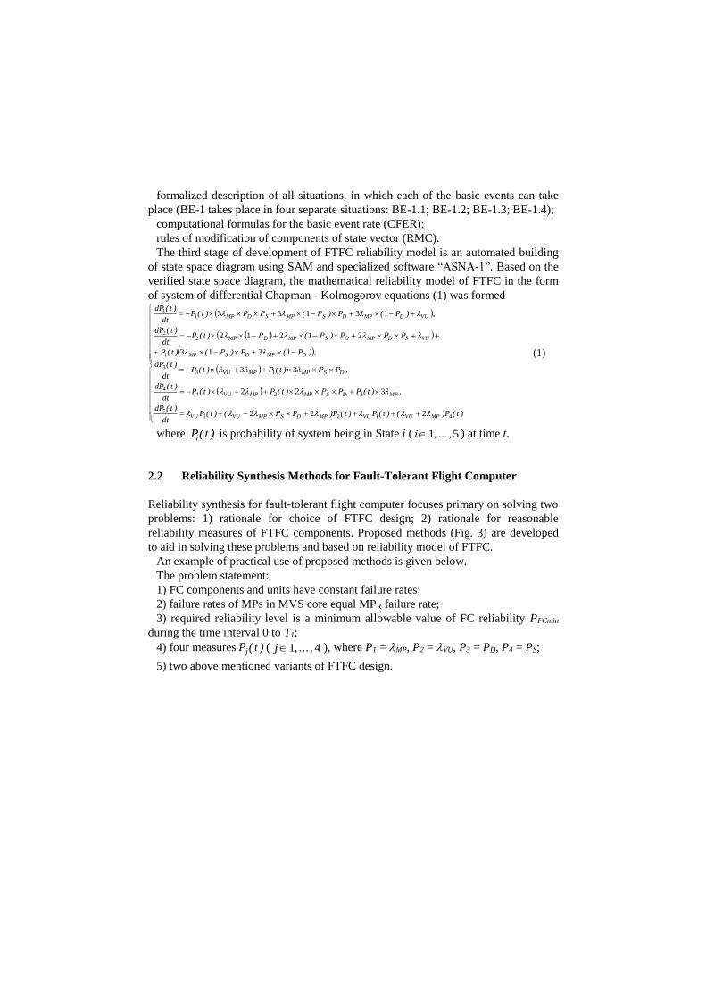
2.2 Reliability Synthesis Methods for Fault-Tolerant Flight Computer
Reliability synthesis for fault-tolerant flight computer focuses primary on solving two
problems: 1) rationale for choice of FTFC design; 2) rationale for reasonable
reliability measures of FTFC components. Proposed methods (Fig. 3) are developed
to aid in solving these problems and based on reliability model of FTFC.
An example of practical use of proposed methods is given below.
The problem statement:
1) FC components and units have constant failure rates;
2) failure rates of MPs in MVS core equal MPR failure rate;
3) required reliability level is a minimum allowable value of FC reliability PFCmin
during the time interval 0 to T1;
4) four measures )t(Pj ( 41 ,...,j ), where P1 = MP, P2 = VU, P3 = PD, P4 = PS;
5) two above mentioned variants of FTFC design.
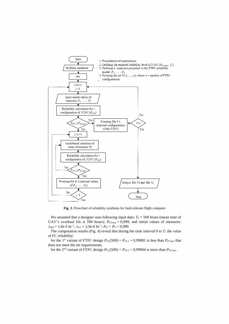
Fig. 3. Flowchart of reliability synthesis for fault-tolerant flight computer
We assumed that a designer uses following input data: T1 = 500 hours (mean time of
UAV’s overhaul life is 500 hours); PFCmin = 0,999; and initial values of measures:
MP = 1,8e-5 hr-1; VU = 2,9e-6 hr-1; PD = PS = 0,999.
The computation results (Fig. 4) reveal that during the time interval 0 to T1 the value
of FC reliability:
for the 1st variant of FTFC design PFC(500) = PFC1 = 0,99881 is less than PFCmin that
does not meet the set requirements;
for the 2nd variant of FTFC design PFC(500) = PFC2 = 0,99904 is more than PFCmin.

Fig. 4. Graphs of flight computer reliability: 1 – no additional standby microprocessors; 2 –
with inherent standby microprocessor
The researches, using the above-mentioned input data, allow rationalizing reliability
requirements to FTFC components and drawing next conclusions:
1. In order to maintain required reliability level of FTFC without standby MPs in
MVS core, it is necessary to rise reliability requirements to MPs (MP ≤ 8e-5 hr-1) or
VU (VU ≤ 2,3e-6 hr-1) reliability.
2. FTFC design with implementation of MVS 2-out-of-3 MPs and inherent MP as
well as DSD allows increasing reliability to required level without changing
requirements to reliability of MPs and VU. In addition, it is possible to scale back
requirements to DSD effectiveness.
3. Using the proposed methods and set input data, we can advise the UAV designer
two above examined variants of FTFC as its reasonable configurations.
3 Reliability Synthesis for Fault-Tolerant Navigation System
Components
3.1 Rationale for Navigation System Components Redundancy
Reliability block diagrams for two navigation system configurations: 1) without
redundancy; 2) with dual modular redundancy (DMR) for gyroscopes and
accelerometers in inertial measurement unit (IMU), are depicted in Fig. 5. The
denotation IS was used for the integrated subsystem, which includes two parts: air
data subsystem (ADS); magnetometer (MM).

IMU
Gx
GPS
KF-1
IS
Gy Gz Ax Ау Аz
1)
IMU
Gx1
GPS
KF-1
IS
Gx2
Gy1
Gy2
Gz1
Gz2
Аx1
Аx2
Ау1
Ау2
Аz1
Аz2
2)
Fig. 5. Reliability block diagram of navigation system: 1) without redundancy for gyroscopes
and accelerometers; 2) with dual redundancy for gyroscopes and accelerometers
Multi-sensor information redundancy is implemented in NS. It should provide
required level of reliability. The task is to define the expedient values of reliability
measures of NS components. Failure rates of NS components are chosen as reliability
measures: 1 is failure rate of the onboard GPS; 2 = 3 = 4 = G – failure rates of
gyroscopes (Gx, Gy, Gz); 5 = 6 = 7 = A – failure rates of accelerometers (Ax, Ay,
Az); 8 is failure rate of IS (sum of failure rates of ADS, MM and PS); 9 is failure
rate of KF-1. Since main and standby gyroscopes and accelerometers have the same
circuitry, so their failure rates are equal.
Kalman Filter KF-1 performs linear quadratic estimation and integration of the data
from GPS, IMU and IS [12]. A failure of KF-1 causes a failure of navigation system.
That is why there is a necessity to rationalize using KF-1 fault-tolerant design, for
example, dual redundant Kalman Filter or implementation of majority-voting
structure.
Onboard GPS is a main source of the navigation data [3, 4, 12]. It is accepted that a
signal from global GPS comes securely. If onboard GPS is failed and IMU is in
operating state, the navigation data comes from IMU. When onboard GPS and IMU
are failed, integrated subsystem supplies the navigation data.
Reliability calculation was conducted for two above-mentioned variants of NS
structure (Fig. 5). For the second configuration it considered that DSDs perform their
functions with probability of successful failure detection PD = 1 and probability of
successful completion of switching procedure PS = 1. It was assumed that duration of
all processes and procedures, which take place in NS, are distributed according to an
exponential law.
It considered that the designer uses the next input data for reliability synthesis for
NS: time interval T1 = 500 hours; minimum allowable value of NS reliability
PNSmin = 0,999; initial values of failure rates of NS components: 1 = 3e-4 hr-1;
G = 9e-5 hr-1; A = 6e-5 hr-1; 8 = 4e-4 hr-1, 9 = 1,6e-6 hr-1.
The computation results for two variants of NS proved expediency of DMR for
gyroscopes and accelerometers in IMU. Reliability value for the 1st variant of NS is
PNS(500) = PNS1 = 0,99411 that less than PNSmin. Implementation of dual redundancy
for gyroscopes and accelerometers allows to increase NS reliability to the value
PNS(500) = PNS2 = 0,99903 and provide required reliability level on the interval of
T2 = 845 hr. These conclusions were drawn considering that DSD perform their

functions with probability equals 1. To raise adequacy of NS reliability model it was
proposed to develop a reliability model of fault-tolerant unit with dual modular
redundancy and taking into account the real DSD effectiveness: PD < 1 and PS < 1.
3.2 Reliability Model of Fault-Tolerant Unit with Dual Redundancy and
Taking into Account Detection and Switching Devices Effectiveness
A reliability model was developed according to the methods presented in [9, 20]:
1) Forming a verbal model of fault-tolerant unit (FTU).
The model includes reliability measures (M – failure rate of the main part and R –
failure rate of standby part of FTU) and DSD effectiveness measures (probability of
successful completion of detection procedure – PD and probability of successful
completion of switching procedure – PS).
A detection device controls continuously operability of the main FTU part. If
detection procedure is successful (the detection device defines a failure of the main
part), the detection device will transfer a signal to the switching device that unhooks
the main part and hooks up the standby part.
If detection procedure is unsuccessful, fault-tolerant unit will come to state of
critical failure. In addition, FTU will come to state of critical failure, if detection
procedure is successful but the switching procedure is unsuccessful.
2) The state vector consists of two components: V1 – a state of main part (1, 0;
initial value V1 = 1); V2 – a state of standby part (1, 0; initial value V2 = 1).
The basic events of reliability behavior of FTU: BE-1 – “Failure of main part”; BE-
2 – “Completion of detection procedure”; BE-3 – “Completion of switching
procedure”; BE-4 – “Failure of standby part”.
3) The fault-tolerant unit is in critical failure state, when there is a failed main part
and standby part is not hooked up: V1 = 0.
The developed state space diagram for the investigated FTU with dual redundancy
and taking into account DSD effectiveness is presented in Table 3.
The model simplification was used on the basis that the research object is described
by one group of procedures with long duration and another group of procedures with
much less duration. This condition simplifies the model however reduces the degree
of its adequacy. The detection procedure is auxiliary in the structure of FTU. If do not
take into account duration of procedure in 20 ms, computation of FCS reliability for
the UAV flight time interval (up to 10 hours) brings not significant error. For the
proposed mathematical model, the next simplifications were done: duration of
detection procedure TD = 0 and switching procedure – TS = 0. Accordingly, the basic
events BE-2 and BE-3 are concurrent with BE-1 and got denotations CBE-2 and
CBE-3.
Table 3. State space diagram for fault-tolerant unit with dual modular redundancy and taking
into account detection and switching effectiveness
Step
Previous
State and
actual BE
Probability of
alternative
continuation of
Next
State
after BE
State
Transition
from State to
State
Computational
formula for the BE
rate

process V1 V2
1 Initial state 1 1 1
2
1BE-1
(CBE-2,
CBE-3)
(1–PD) 0 1 CF 1 → CF λM(1–PD)
PDPS 1 0 2 1 → 2 λMPDPS
PD(1–PS) 0 1 CF 1 → CF λMPD(1–PS)
3 1BE-4 1 0 2 1 → 2 λR
4 2BE-1
(CBE-2)
(1–PD) 0 0 CF 2 → CF λM(1–PD)
PD 0 0 CF 2 → CF λMPD
It was taken into account that the duration of all procedures in research object are
random variables having an exponential distribution, and a number of events on the
observation interval is defined by the Poisson distribution. In accordance with the
methods presented in [9, 20], the components of FTU structural-automaton model
were formed (Table 4).
Table 4. Structural-automaton model of fault-tolerant unit with dual modular redundancy and
taking into account detection and switching effectiveness
Basic event
(concurrent basic events)
Formalized presentation of
situations CFER RMC
BE-1 “Failure of main part”
(CBE-2, CBE-3)
1. (V1=1) AND (V2=1) λMPDPS V2:=0
λM(1 – PD) V1:=0
λMPD(1 – PS) V1:=0
2. (V1=1) AND (V2=0) λMPD V1:=0
λM(1 – PD) V1:=0
BE-4 “Failure of standby part” 1. (V1=1) AND (V2=1) λR V2:=0
The mathematical reliability model of fault-tolerant unit (2) was formed
).t(P)t(P)РP(dt
)t(dP
),t(Р)t(P)РP(dt
)t(dP
),t(P)(dt
)t(dP
MSDM
MRSDM
RM
213
212
11
1
(2)
where )t(Pі is probability of system being in State i ( 31 ,...,і ) at time t.
3.3 Estimation of Reliability Measures for Navigation System and its
Components in view of Detection and Switching Effectiveness
The same assumptions and input data were used as in the section 3.1. Results of
reliability estimation for the 2nd variant of NS and its components (units of gyroscopes

(UG) and accelerometers (UA)) with perfect and non-perfect DSD are presented in
Table 5.
Table 5. Results of reliability estimation for the 2nd variant of NS and its components in view
of detection and switching effectiveness
Input data Output data
DSD PS PD PUG(500) PUA(500) PNS2(500)
perfect 1 1 0,9981 0,9991 0,99903
non-perfect 0,999 0,999 0,9979 0,9989 0,99901
0,99 0,99 0,9974 0,9982 0,99892
0,94 0,99 0,9957 0,9978 0,99871
0,98 0,98 0,9967 0,9979 0,99884
The graphs of UG reliability at different values of DSD effectiveness are shown in
Fig. 6.
Fig. 6. Graphs of UG reliability at different values of PD and PS: 1 – PD = PS = 1; 2 –
PD = PS = 0,999; 3 – PD = PS = 0,99; 4 –PD = PS = 0,98
The results, presented in Table 5 and Fig. 6, confirm that reliability depends on the
detection and switching effectiveness. The proposed model gives an opportunity to
rationalize necessary values of measures of DSD effectiveness.
3.4 Reliability Synthesis Methods for Navigation System Components
Proposed reliability synthesis methods are developed for fault-tolerant NS
components. They are based on reliability models of NS components and use of

specialized software ASNA-1. The main difference of these methods from the
mentioned above methods (section 2.2) is that for reliability synthesis for NS we can
investigate rational variants of fault-tolerant modules (units). Using reliability
synthesis methods for FC we evaluated fault-tolerant units with DMR for gyroscopes,
accelerometers, Kalman Filter (KF-1). We used following input data: T1 = 500 hours;
PNSmin = 0,999. The computation results, which indicate reasonable reliability
measures of NS components, are presented in Table 6.
Table 6. Rational reliability measures of NS components at different values of PD and PS
Input data Output data
PS PD G , hr -1 А, hr -1 9, hr -1
0,98 0,99 6,4e-5 3,7e-5 2,4e-5
0,96 0,99 5,5e-5 2,8e-5 1,7e-5
0,94 0,99 4,4e-5 2,4e-5 1,3e-5
0,92 0,98 3,7e-5 1,8e-5 9,1e-6
0,9 0,97 2,6e-5 1,6e-5 7,4e-6
Hence, these methods allow adjusting with designer the acceptable values of
reliability measures of NS components as well as measures of DSD effectiveness.
4 Conclusions
1. A necessity and actuality of improvement of existent models and methods of
reliability synthesis for fault-tolerant systems have been rationalized in making
decisions on design of UAV flight control system.
2. The developed reliability models of navigation system and flight computer
represent the different variants of fault-tolerant designs and have a high level of
adequacy.
3. Based on the models, we proposed the reliability synthesis methods for
components of UAV flight control system. Automation of multiple analysis
procedures allows quickly (during a few hours) making reasonable design decisions.
4. Reliability requirements and recommendations for rational choice of fault-tolerant
designs of navigation system and flight computer have been developed to meet
required reliability level.
5. We are planning further research studies to investigate reliability of UAV
autopilot and its fault-tolerant modules, availability of all FCS components as well as
solving optimization problems.
References
1. Unmanned Aerial Vehicle Reliability Study, 20-21, 29 (2003)

2. 21st Century Unmanned Aerial Vehicles (UAV). Unmanned Aerial Vehicle Reliability
Study. Office of the Secretary of Defense. OSD UAV Reliability Study Executive
Summary, 9-26 (2010)
3. Shawn Reimann, Jeremy Amos, Erik Bergquist, Jay Cole, Justin Phillips, Simon Shuster.
UAV for Reliability – Aerospace Vehicle Design, 2, 5-13, 18-21 (2013)
4. Greg Caswell and Ed Dodd. Improving UAV Reliability. DfR Solutions, 1-5 (2014)
5. Peck Michael. Pentagon Unhappy About Drone Aircraft Reliability. National Defence
Magazine, May 2003 (2003)
6. Israel Koren, C. Mani Krishn. Fault tolerant systems. Morgan Kaufmann Publishers is an
imprint of Elsevier, 11-33, (2007)
7. Dubrova E. Fault tolerant design: an introduction. Department of Microelectronics and
Information Technology Royal Institute of Technology Stockholm, Sweden. Kluwer
Academic Publishers, 1-4, 14, 27-41, 27-55 ( 2007)
8. Yinong Chen, Tinghuai Chen. Implementing Fault-Tolerance via Modular Redundancy
with Comparison. IEEE Transactions on reliability, vol. 39, № 2, 217–225 (1990)
9. B. Volochiy. Modelling Technology of Information Systems Behavior. Monograph. Lviv
Polytechnic National University Publ., 59-102 (2004) [in Ukrainian]
10. C. B. Feldstein and J. C. Muzio. Development of a Fault Tolerant Flight Control System.
University of Victoria, Victoria, British Columbia, Canada (2004)
11. Rudaba Khan, Paul Williams, Paul Riseborough, Asha Rao, Robin Hill. Active Fault
Tolerant Flight Control System Design - A UAV Case Study. Available at:
https://arxiv.org/abs/1610.03162v1 (2016)
12. Ducard, Guillaume J. J. Fault-tolerant Flight Control and Guidance Systems. Practical
Methods for Small Unmanned Aerial Vehicles. 2009, XXII, 264 p. Hardcover.
13. Yuta Kobayashi and Masaki Takahashi. Design of Intelligent Fault-Tolerant Flight Control
System for Unmanned Aerial Vehicles. Keio University. Japan. Nihon Kikai Gakkai
Ronbunshu, C Hen/Transactions of the Japan Society of Mechanical Engineers, Part C,
2301-2310 (2009)
14. Xiao-Lin ZHANG1, Hai-Sheng Li2, Dan-Dan YUAN. Dual Redundant Flight Control
System Design for Microminiature UAV. 2nd International Conference on Electrical,
Computer Engineering and Electronics. (2015).
15. MIL-HDBK-217 F Notice 2. Reliability Prediction of Electronic Equipment. Deparment of
Defence. Washington DC. Appendix A (1995)
16. Reliability/Availability of Electrical & Mechanical Systems for C4ISR Facilities.
Department of the Army, TM 5-698-1, 14-18, 20-22, 27-34 (2003)
17. Vesely William, Michael Stamatelatos, Joanne Dugan, Joseph Fragola, Joseph Minarick
III, Jan Railsback. Fault Tree Handbook with Aerospace Applications. NASA
Headquarters: Washington, 195-202 (2002)
18. Joanne Bechta Dugan. Fault trees and Markov models for reliability analysis of fault
tolerant systems. Reliability Engineering & System Safety. Vol. 39, 291-307 (1993)
19. B. Volochiy, L. Ozirkovkyy, M. Zmysnyi, I. Kulyk. Designing of Fault-Tolerant Radio
Electronic Systems with Complex Majority Structures. Radioelectronic and Computer
Systems. Kharkiv. National Aerospace University, № 6 (80), 120-129 (2016)
20. D. Fedasyuk, S. Volochiy. Method of Developing of Structural-Automaton Models of
Fault-Tolerant systems. 14th International Conference. The Experience of Designing and
Application of CAD Systems in Microelectronics. Proceeding, 22 26 (2017)


