
Reliability Report - Lafayette College
29
RELIABILITY REPORT 1 Latest Revision: 12 May 2014 Prepared by: Drew Jeffrey Abstract This document presents an analysis of the LFEV-ESCM 2014 system according to MIL-HDBK-217F to prove that the system can operate without failure for at least 1000 hours. Reliability Report ECE 492 – Spring 2014
Transcript of Reliability Report - Lafayette College

RELIABILITY REPORT 1
Latest Revision: 12 May 2014
Prepared by: Drew Jeffrey
Abstract This document presents an analysis of the LFEV-ESCM 2014 system according to
MIL-HDBK-217F to prove that the system can operate without failure for at least
1000 hours.
Reliability Report
ECE 492 – Spring 2014

RELIABILITY REPORT 2
Table of Contents EXECUTIVE SUMMARY 6
INTRODUCTION 6
FAILURE ANALYSIS 6
COMPILED FAILURE RATES 7
BATTERY PACK SYSTEM FAILURES 8
MECHANICAL FAILURES 8
DISCHARGE PATH 8
CHARGING PATH 8
ACCUMULATOR CONTAINER 9
PACK MANAGER 9
CELL AMS BOARDS 9
BATTERY PACK OVERALL FAILURE RATE 10
CHARGER SYSTEM FAILURES 11
CHARGER OVERALL FAILURE RATE 11
APPENDIX A: PACK MECHANICAL DETAILED FAILURE ANALYSIS 12
VEAM POWERLOCK CONNECTORS (QUANTITY – 2) 12
CHARGER ANDERSON CONNECTOR PLUG (QUANTITY –1) 12
GIGAVAC GX14CAB, 350+ AMP ISOLATION RELAY (AIRS) (QUANTITY – 2) 12
4-PIN MATE-N-LOK CONNECTOR (QUANTITY – 2) 12
6-PIN MATE-N-LOK CONNECTOR (QUANTITY – 1) 12
DIN RAIL TERMINAL BLOCKS (QUANTITY – 37) 13

RELIABILITY REPORT 3
LITTELFUSE 30A CHARGING FUSES (QUANTITY – 2) 13
ZORO TOOLS G3475534 200A DISCHARGING FUSE (QUANTITY – 1) 13
GIGAVAC P105CDA, 50 AMP CHARGING RELAY (QUANTITY – 2) 13
60AH BATTERY CELLS (QUANTITY – 7) 13
APPENDIX B: PACK MANAGER DETAILED FAILURE ANALYSIS 14
4X20 CHARACTER LCD DISPLAY (QUANTITY – 1) 14
16-PIN SHROUDED HEADER (QUANTITY – 2) 14
10-PIN SHROUDED HEADER (QUANTITY – 1) 14
6-PIN SHROUDED LOCKING HEADER (QUANTITY – 1) 14
8-PIN SCREW TERMINAL (QUANTITY – 2) 14
2-PIN SCREW TERMINAL (QUANTITY – 4) 15
3-PIN SCREW TERMINAL (QUANTITY – 4) 15
CHIP RESISTOR, 1.5MΩ (QUANTITY – 1) 15
CHIP RESISTOR, 100KΩ (QUANTITY – 2) 15
CHIP RESISTOR, 10KΩ (QUANTITY – 4) 15
CHIP RESISTOR, 2KΩ (QUANTITY – 2) 16
CHIP RESISTOR, 1.5KΩ (QUANTITY – 2) 16
CHIP RESISTOR, 1KΩ (QUANTITY – 1) 16
CHIP RESISTOR, 470Ω (QUANTITY – 2) 16
CERAMIC CHIP CAPACITOR, 0.1UF (QUANTITY – 9) 17
CERAMIC CHIP CAPACITOR, 22UF (QUANTITY – 1) 17
ELECTROLYTIC CAPACITOR, 220UF (QUANTITY – 1) 17
D1N4148 DIODE THROUGH HOLE (QUANTITY – 3) 17
D1N4001 DIODE THROUGH HOLE (QUANTITY – 1) 17
RELIABILITY REPORT 4
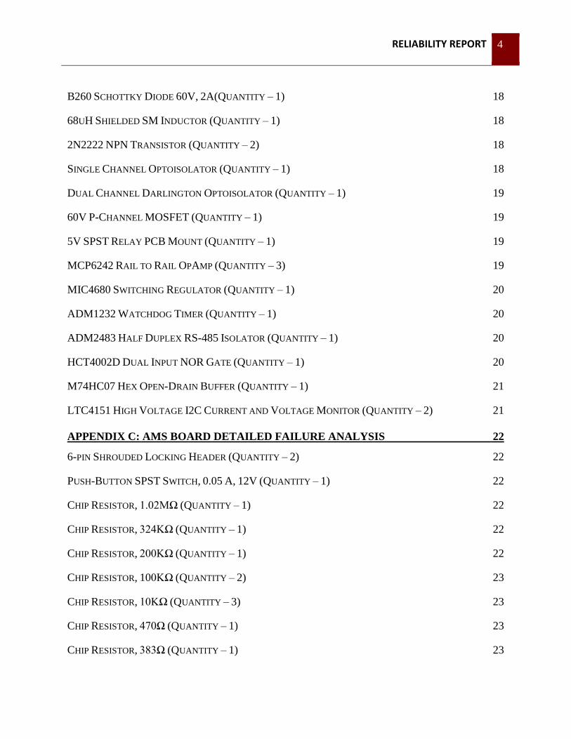
B260 SCHOTTKY DIODE 60V, 2A(QUANTITY – 1) 18
68UH SHIELDED SM INDUCTOR (QUANTITY – 1) 18
2N2222 NPN TRANSISTOR (QUANTITY – 2) 18
SINGLE CHANNEL OPTOISOLATOR (QUANTITY – 1) 18
DUAL CHANNEL DARLINGTON OPTOISOLATOR (QUANTITY – 1) 19
60V P-CHANNEL MOSFET (QUANTITY – 1) 19
5V SPST RELAY PCB MOUNT (QUANTITY – 1) 19
MCP6242 RAIL TO RAIL OPAMP (QUANTITY – 3) 19
MIC4680 SWITCHING REGULATOR (QUANTITY – 1) 20
ADM1232 WATCHDOG TIMER (QUANTITY – 1) 20
ADM2483 HALF DUPLEX RS-485 ISOLATOR (QUANTITY – 1) 20
HCT4002D DUAL INPUT NOR GATE (QUANTITY – 1) 20
M74HC07 HEX OPEN-DRAIN BUFFER (QUANTITY – 1) 21
LTC4151 HIGH VOLTAGE I2C CURRENT AND VOLTAGE MONITOR (QUANTITY – 2) 21
APPENDIX C: AMS BOARD DETAILED FAILURE ANALYSIS 22
6-PIN SHROUDED LOCKING HEADER (QUANTITY – 2) 22
PUSH-BUTTON SPST SWITCH, 0.05 A, 12V (QUANTITY – 1) 22
CHIP RESISTOR, 1.02MΩ (QUANTITY – 1) 22
CHIP RESISTOR, 324KΩ (QUANTITY – 1) 22
CHIP RESISTOR, 200KΩ (QUANTITY – 1) 22
CHIP RESISTOR, 100KΩ (QUANTITY – 2) 23
CHIP RESISTOR, 10KΩ (QUANTITY – 3) 23
CHIP RESISTOR, 470Ω (QUANTITY – 1) 23
CHIP RESISTOR, 383Ω (QUANTITY – 1) 23

RELIABILITY REPORT 5
CHIP RESISTOR, 200Ω (QUANTITY – 1) 23
CHIP RESISTOR, 100Ω (QUANTITY – 1) 24
CHIP RESISTOR, 36Ω (QUANTITY – 1) 24
POWER RESISTOR, 0.75Ω, 20W (QUANTITY – 1) 24
CERAMIC CHIP CAPACITOR, 680PF (QUANTITY – 1) 24
CERAMIC CHIP CAPACITOR, 0.1UF (QUANTITY – 5) 24
CERAMIC CHIP CAPACITOR, 1UF (QUANTITY – 1) 25
CERAMIC CHIP CAPACITOR, 10UF (QUANTITY – 3) 25
CHIP LED RED, 2MA SMD (QUANTITY – 1) 25
CHIP LED YELLOW, 2MA SMD (QUANTITY – 1) 25
CHIP LED GREEN, 2MA SMD (QUANTITY – 1) 25
SCHOTTKY DIODE 20VDC, 500MA (QUANTITY – 1) 26
10UH SEMI-SHIELDED SM INDUCTOR (QUANTITY – 1) 26
TIP102 DARLINGTON NPN POWER TRANSISTOR (QUANTITY – 1) 26
LTV-357T SINGLE CHANNEL OPTOISOLATOR (QUANTITY – 1) 26
PIC16(L)F1826/27 (QUANTITY – 1) 26
MCP6242 RAIL TO RAIL OPAMP (QUANTITY – 1) 27
LT1307 DC-DC SWITCHING REGULATOR (QUANTITY – 1) 27
MCP9700 LINEAR THERMISTOR TEMP SENSOR SOT-23-3 (QUANTITY – 1) 27
3.3V LDO VOLTAGE REGULATOR 500MA (QUANTITY – 1) 27
DUAL I2C ISOLATOR (QUANTITY – 1) 28
APPENDIX D: CHARGER DETAILED FAILURE ANALYSIS 29
TDK-LAMBDA GENH30-25 POWER SUPPLY (QUANTITY – 1) 29
CHARGER ANDERSON CONNECTOR PLUG (QUANTITY – 3) 29

RELIABILITY REPORT 6
Executive Summary
Introduction Characterizing the performance of a system involves more than simply observing its successful
operation. A system must also be operational for a useful lifetime and estimating the reliability
of a system can help engineers and customers alike understand the cost of maintenance over its
lifetime. In order to make sure that the LFEV-ESCM system meets the reliability standards
established in ECE 492, both analysis and testing will be performed. The reliability test, a 24-
hour operation of the system, will be performed according to the ATP. In this document, the
potential failures of the system are identified and analyzed according to manufactures’ datasheets
and MIL-HDBK-217F to ensure the system can operate for 1000 hours without failure as per
GPR006.
The LFEV-ESCM 2014 system deliverables consist of two major components, the battery pack
and a compatible charger. These two systems will be analyzed in-depth for reliability. These
two components will be integrated into the full LFEV-ESCM comprised of the Safety Controller,
Load Controller, and GLV Power from the LFEV-ESCM 2013 system. Reliability figures for
the 2013 subsystems will be obtained from the Reliability Memo found on the Spring 2013
team’s website under the Acceptance Testing section.
Failure Analysis Since the likelihood of a failure in 1000 hours of operation is of primary interest, the number of
expected failures in a 1000-hour period is calculated. Each failure is independent of other
failures, so by adding the number of failures per million hours and converting to failures per
thousand hours, our equation for number of failures per 1000 hours becomes:
∑(
) (
)
Appendix A details the analysis on the probability of failure for each individual part. Based on
details recorded in Appendix A, an overall calculation for the number of failures per 1000 hours
could be obtained.

RELIABILITY REPORT 7
Compiled Failure Rates
Subsystem Failures/1000 hours
Battery Pack (All Cycles) 3.203 (continuous), 1.104 (4x cycle period),
0.6565 (powerlock conn. stay plugged)
Charger 0.0304
Safety Controller 0.095
Load Controller 0.0024
GLV Power ≤ 0.01
All Systems 3.341 (continuous cycling), 1.242 (4x cycle period),
0.794 (powerlock conn. stay plugged)
According to the failure rate analysis contained within this document, our system can
successfully operate with a mean time between failure of 805.2 hours when charged and
discharged at a rate of one cycle per 576 mins (8.93 hours). Although this value of reliability
will not met requirement GPR006, this calculation is a worst case scenario and is a result of
unplugging the powerlock connectors once per cycle. Under normal operation of the battery
pack, the powerlock connectors could remain plugged in during both discharge and charging
cycles, reducing the number of failures per million hours of the powerlock connectors to around
1 or 2. Using this estimation would drop the number of failures per 1000 hours to around 0.794
and thereby increase the MTBF to 1259 hours, meeting requirement GPR006. Our reliability is
further verified by completion of T007 in the Acceptance Test Plan.

RELIABILITY REPORT 8
Battery Pack System Failures
Mechanical Failures
Discharge Path
The battery pack, being an intricate mechanical assembly, depends on the integrity of its
mechanical connections in order to function. Any break in the discharging or charging current
paths, which have many points of connection, interrupts the current and causes a failure. By
applying probability to our pack construction:
( ) ( ) ∑ ( )
Here, n is the number of individual mechanical connections in the current path.
As per appendix A, the mean time between failure for the discharge path when considering the
powerlock connectors, safety loop connectors, SCADA RS-485 connector, discharging fuse, and
AIRs was 3904 failures per million hours or 3.9 failures/thousand hours. Although this
calculation seems high and will therefore not meet GPR006, this calculation assumes continuous
charging and discharging cycles over the entire 1000 hour period. If the system is charged and
discharged with a cycle time 4 times slower than the continuous cycle model (536 mins instead
of the 134 min cycle used in the calculations), a failure rate of 0.9923 failures/1000 hours will be
encountered. Since the battery pack will likely not be put under a series of continuous charge
and discharge cycles in its normal operation, the MTBF will most likely stay below 1000 hours
as shown by the 4x longer cycle period calculation.
As of the time of system integration and ATP, there is no data available to determine the
reliability of the bolted aluminum pieces which comprise the current path. Therefore, there is no
accurate way to determine the complete reliability of the current path over our battery pack’s
lifetime. However, the Pack Management Systems and AMS are more complicated and seem to
be prone to more errors than the discharging current path, so it is likely that the number of errors
per 1000 hours in the Pack Manager and AMS are much higher than any errors attributed to
mechanical systems and will therefore overshadow the mechanical contribution to the number of
errors per 1000 hours.
Charging Path
The battery pack’s charging path contains many of the same mechanical joints as the discharge
path with the exception of the powerlock connectors on the positive and negative terminal ends
of the battery pack. Since the powerlock connectors were the primary contributor to mechanical

RELIABILITY REPORT 9
failures in the battery pack, the mean time between failure for the charging path is much less.
The charging path consists of the mechanical interconnects between battery cells, fuses, charge
relays, Anderson plug, SCADA RS-485 connector, and wires connecting these components
together. Safety loop is not considered since during charging the safety loop does not need to be
closed. According to appendix A when considering the charge relays, fuses, and Anderson plug
in the charging path, the number of errors per 1000 hours was 2111.29 failures/million hours or
2.11 failures/thousand hours. The primary contributor to this failure calculation is the battery
cells themselves as they are only rated for around 1500 cycles of charge and discharge. If a
charge/discharge cycle period 4x longer than the continuous cycling period is used, the number
of failures per 1000 hours drops to 0.544. As with the calculation for the discharging path, there
is no way to obtain a mean time between failure for the complete charging path as there is no
reliability information for the aluminum bars connected between each of the battery cells.
Accumulator Container
Many of the mechanical components of the battery pack were custom made. As such, it is very
difficult to estimate the reliability of the mechanical components without further testing of the
system in stress tests. This reliability analysis does not take into account any failures which may
occur to any of the custom machined pieces of the battery pack as computer simulations might be
necessary to obtain an accurate failure rate for those pieces.
Pack Manager The pack manager consists of both a custom-designed PCB board with soldered components and
a Linux-based ARM computer. The battery pack requires both to be functional in order for the
pack manager to operate correctly. As such, the probability of failure for the Pack Manager is
given by:
( ) ( ( )) ( ( ))
In Appendix B, failure analysis is recorded for each electrical component used on the Pack
Manager Breakout Board. With these values, the number of errors per 1000 hours for the
breakout board is 35.3 failures per million hours or 0.0353 failures per 1000 hours. This analysis
does not account for any software related failures as information about the TS-8160-4200
reliability could not be found and getting an accurate estimate for software relate errors will
require time and experimentation which we do not have currently at this stage in the project.
Cell AMS Boards In order to obtain voltage and temperature readings from each cell, a small circuit board with
voltage and temperature sensors was placed on the top of each battery cell. It is dangerous to
attempt to continue normal operations without knowing the current state of each cell in the pack,
so the current version of the Pack Manager software will cease normal discharge and charge
RELIABILITY REPORT 10
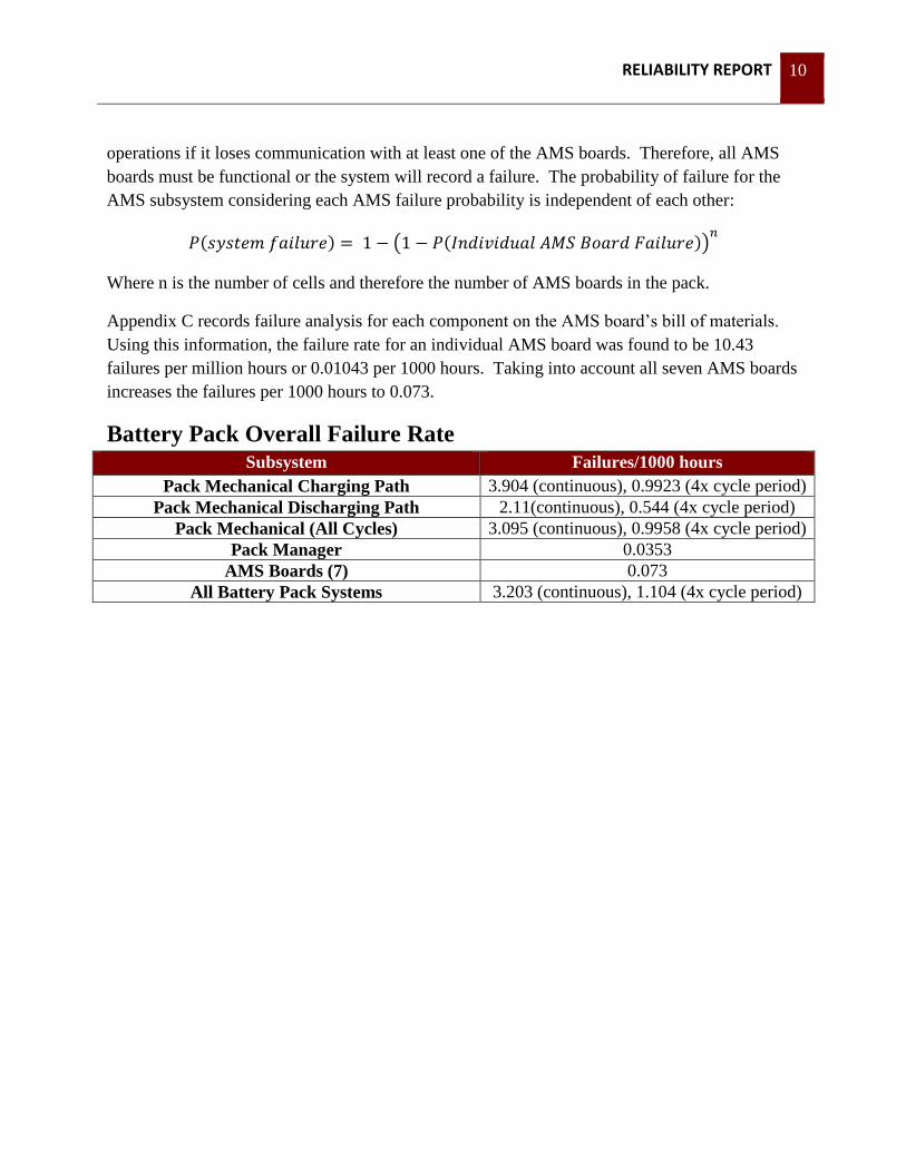
operations if it loses communication with at least one of the AMS boards. Therefore, all AMS
boards must be functional or the system will record a failure. The probability of failure for the
AMS subsystem considering each AMS failure probability is independent of each other:
( ) ( ( ))
Where n is the number of cells and therefore the number of AMS boards in the pack.
Appendix C records failure analysis for each component on the AMS board’s bill of materials.
Using this information, the failure rate for an individual AMS board was found to be 10.43
failures per million hours or 0.01043 per 1000 hours. Taking into account all seven AMS boards
increases the failures per 1000 hours to 0.073.
Battery Pack Overall Failure Rate Subsystem Failures/1000 hours
Pack Mechanical Charging Path 3.904 (continuous), 0.9923 (4x cycle period)
Pack Mechanical Discharging Path 2.11(continuous), 0.544 (4x cycle period)
Pack Mechanical (All Cycles) 3.095 (continuous), 0.9958 (4x cycle period)
Pack Manager 0.0353
AMS Boards (7) 0.073
All Battery Pack Systems 3.203 (continuous), 1.104 (4x cycle period)

RELIABILITY REPORT 11
Charger System Failures The charging unit being used for the current system is relatively simple compared to the battery
pack. It uses a TDK-Lambda GENH30-25 Power Supply to produce a constant charging current
to the battery pack. To connect the power supply to the battery pack, a cable using Anderson
connectors is utilized. In the current design, 3 sets of Anderson plugs are in the charging current
path of the charger. The charger system will fail if any connection in the charging current path
or the power supply itself fails. The probability of failure for the charger is given by:
( ) ( ( )) ( ( ))
Charger Overall Failure Rate The detailed failure rate for the charger components is recorded in Appendix D. Based on the
component failure rates, the overall failure rate for the charger subsystem is 30.36 failures per
million hours or 0.0304 failures per 1000 hours.
RELIABILITY REPORT 12
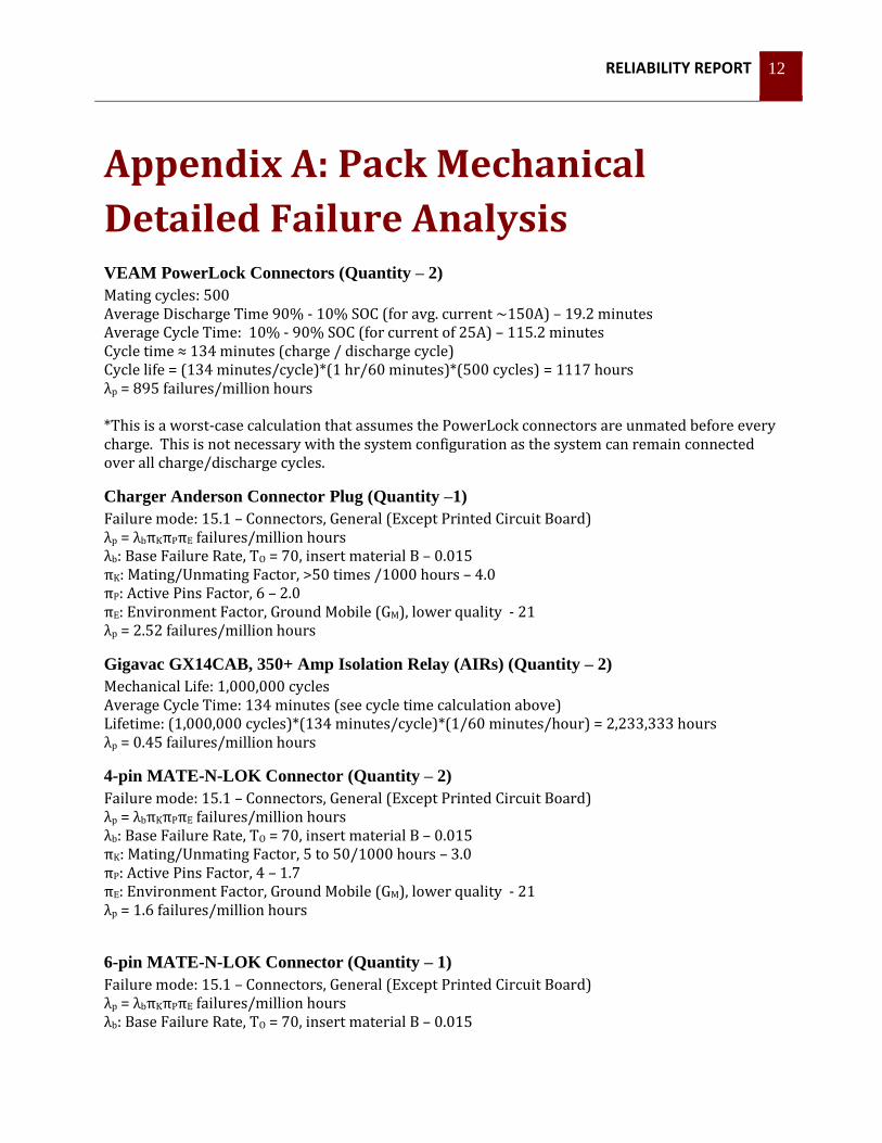
Appendix A: Pack Mechanical
Detailed Failure Analysis VEAM PowerLock Connectors (Quantity – 2)
Mating cycles: 500 Average Discharge Time 90% - 10% SOC (for avg. current ~150A) – 19.2 minutes Average Cycle Time: 10% - 90% SOC (for current of 25A) – 115.2 minutes Cycle time ≈ 134 minutes (charge / discharge cycle) Cycle life = (134 minutes/cycle)*(1 hr/60 minutes)*(500 cycles) = 1117 hours λp = 895 failures/million hours *This is a worst-case calculation that assumes the PowerLock connectors are unmated before every charge. This is not necessary with the system configuration as the system can remain connected over all charge/discharge cycles.
Charger Anderson Connector Plug (Quantity –1)
Failure mode: 15.1 – Connectors, General (Except Printed Circuit Board) λp = λbπKπPπE failures/million hours λb: Base Failure Rate, TO = 70, insert material B – 0.015 πK: Mating/Unmating Factor, >50 times /1000 hours – 4.0 πP: Active Pins Factor, 6 – 2.0 πE: Environment Factor, Ground Mobile (GM), lower quality - 21 λp = 2.52 failures/million hours
Gigavac GX14CAB, 350+ Amp Isolation Relay (AIRs) (Quantity – 2)
Mechanical Life: 1,000,000 cycles Average Cycle Time: 134 minutes (see cycle time calculation above) Lifetime: (1,000,000 cycles)*(134 minutes/cycle)*(1/60 minutes/hour) = 2,233,333 hours λp = 0.45 failures/million hours
4-pin MATE-N-LOK Connector (Quantity – 2)
Failure mode: 15.1 – Connectors, General (Except Printed Circuit Board) λp = λbπKπPπE failures/million hours λb: Base Failure Rate, TO = 70, insert material B – 0.015 πK: Mating/Unmating Factor, 5 to 50/1000 hours – 3.0 πP: Active Pins Factor, 4 – 1.7 πE: Environment Factor, Ground Mobile (GM), lower quality - 21 λp = 1.6 failures/million hours
6-pin MATE-N-LOK Connector (Quantity – 1)
Failure mode: 15.1 – Connectors, General (Except Printed Circuit Board) λp = λbπKπPπE failures/million hours λb: Base Failure Rate, TO = 70, insert material B – 0.015

RELIABILITY REPORT 13
πK: Mating/Unmating Factor, 5 to 50/1000 hours – 3.0 πP: Active Pins Factor, 6 – 2.0 πE: Environment Factor, Ground Mobile (GM), lower quality - 21 λp = 1.89 failures/million hours
DIN Rail Terminal Blocks (Quantity – 37)
Failure mode: 15.1 – Connectors, General (Except Printed Circuit Board) λp = λbπQπE failures/million hours λp = λbπKπPπE failures/million hours λb: Base Failure Rate, TO = 70, insert material B – 0.015 πK: Mating/Unmating Factor, 0 to 0.05/1000 hours – 1.0 πP: Active Pins Factor, 2 – 1.4 πE: Environment Factor, Ground Mobile (GM), lower quality - 21 λp = 0.441 failures/million hours
Littelfuse 30A Charging Fuses (Quantity – 2)
Failure mode: 22.1 – Fuses λp = λbπE failures/million hours λb: Base Failure Rate 0.010 πE: Environment Factor, Ground Mobile (GM), lower quality - 8.0 λp = 0.080 failures/million hours
Zoro Tools G3475534 200A Discharging Fuse (Quantity – 1)
Failure mode: 22.1 – Fuses λp = λbπE failures/million hours λb: Base Failure Rate 0.010 πE: Environment Factor, Ground Mobile (GM), lower quality - 8.0 λp = 0.080 failures/million hours
Gigavac P105CDA, 50 Amp Charging Relay (Quantity – 2)
Mechanical Life: 1,000,000 cycles Average Cycle Time: 134 minutes (see cycle time calculation above) Lifetime: (1,000,000 cycles)*(134 minutes/cycle)*(1/60 minutes/hour) = 2,233,333 hours λp = 0.45 failures/million hours
60Ah Battery Cells (Quantity – 7)
Cycle Life (according to Spec. Sheet) ≥ 1500 cycles Average Cycle Time: 134 minutes (see cycle time calculation above) Lifetime: (1500 cycles)*(134 minutes/cycle)*(1/60 minutes/hour) = 3,350 hours λp = 298.5 failures/million hours
RELIABILITY REPORT 14
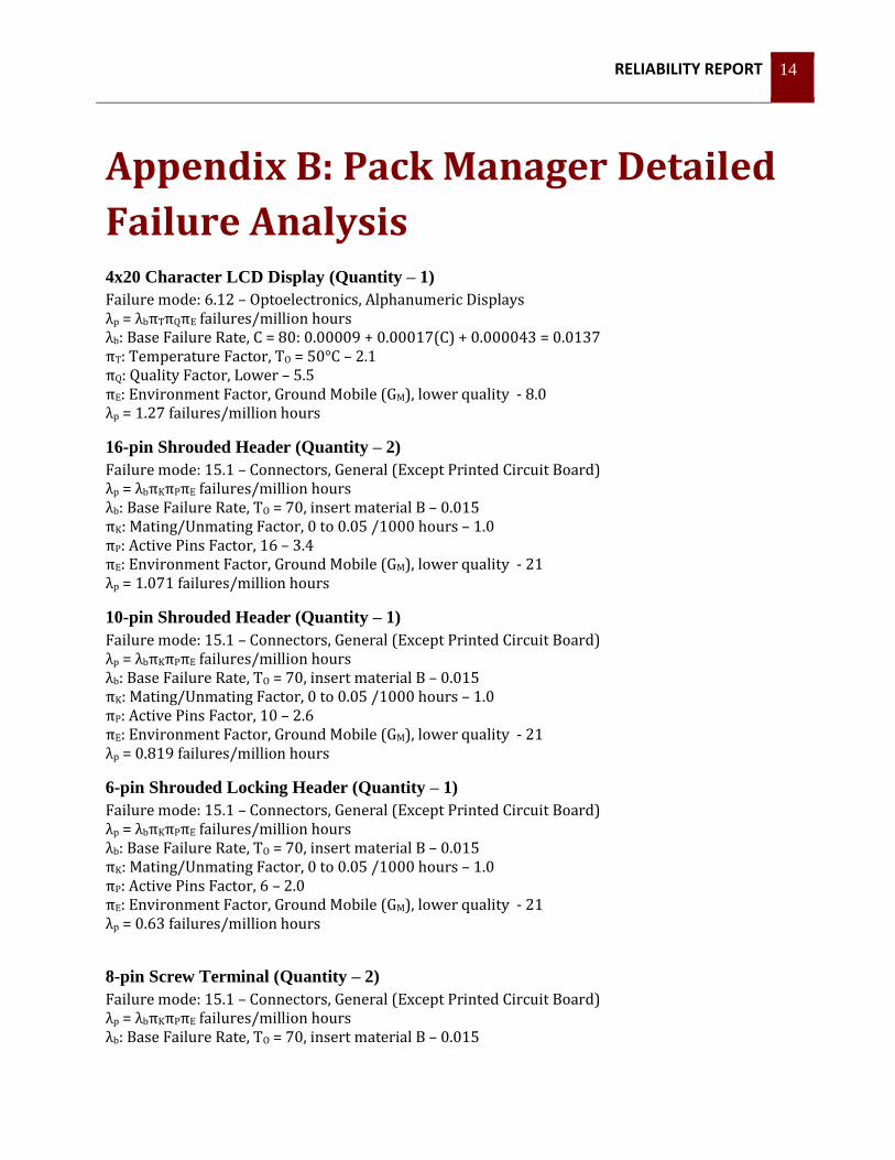
Appendix B: Pack Manager Detailed
Failure Analysis 4x20 Character LCD Display (Quantity – 1)
Failure mode: 6.12 – Optoelectronics, Alphanumeric Displays λp = λbπTπQπE failures/million hours λb: Base Failure Rate, C = 80: 0.00009 + 0.00017(C) + 0.000043 = 0.0137 πT: Temperature Factor, TO = 50°C – 2.1 πQ: Quality Factor, Lower – 5.5 πE: Environment Factor, Ground Mobile (GM), lower quality - 8.0 λp = 1.27 failures/million hours
16-pin Shrouded Header (Quantity – 2)
Failure mode: 15.1 – Connectors, General (Except Printed Circuit Board) λp = λbπKπPπE failures/million hours λb: Base Failure Rate, TO = 70, insert material B – 0.015 πK: Mating/Unmating Factor, 0 to 0.05 /1000 hours – 1.0 πP: Active Pins Factor, 16 – 3.4 πE: Environment Factor, Ground Mobile (GM), lower quality - 21 λp = 1.071 failures/million hours
10-pin Shrouded Header (Quantity – 1)
Failure mode: 15.1 – Connectors, General (Except Printed Circuit Board) λp = λbπKπPπE failures/million hours λb: Base Failure Rate, TO = 70, insert material B – 0.015 πK: Mating/Unmating Factor, 0 to 0.05 /1000 hours – 1.0 πP: Active Pins Factor, 10 – 2.6 πE: Environment Factor, Ground Mobile (GM), lower quality - 21 λp = 0.819 failures/million hours
6-pin Shrouded Locking Header (Quantity – 1)
Failure mode: 15.1 – Connectors, General (Except Printed Circuit Board) λp = λbπKπPπE failures/million hours λb: Base Failure Rate, TO = 70, insert material B – 0.015 πK: Mating/Unmating Factor, 0 to 0.05 /1000 hours – 1.0 πP: Active Pins Factor, 6 – 2.0 πE: Environment Factor, Ground Mobile (GM), lower quality - 21 λp = 0.63 failures/million hours
8-pin Screw Terminal (Quantity – 2)
Failure mode: 15.1 – Connectors, General (Except Printed Circuit Board) λp = λbπKπPπE failures/million hours λb: Base Failure Rate, TO = 70, insert material B – 0.015

RELIABILITY REPORT 15
πK: Mating/Unmating Factor, 0 to 0.05 /1000 hours – 1.0 πP: Active Pins Factor, 8 – 2.3 πE: Environment Factor, Ground Mobile (GM), lower quality - 21 λp = 0.72 failures/million hours
2-pin Screw Terminal (Quantity – 4)
Failure mode: 15.1 – Connectors, General (Except Printed Circuit Board) λp = λbπKπPπE failures/million hours λb: Base Failure Rate, TO = 70, insert material B – 0.015 πK: Mating/Unmating Factor, 0 to 0.05 /1000 hours – 1.0 πP: Active Pins Factor, 2 – 1.4 πE: Environment Factor, Ground Mobile (GM), lower quality - 21 λp = 0.441 failures/million hours
3-pin Screw Terminal (Quantity – 4)
Failure mode: 15.1 – Connectors, General (Except Printed Circuit Board) λp = λbπKπPπE failures/million hours λb: Base Failure Rate, TO = 70, insert material B – 0.015 πK: Mating/Unmating Factor, 0 to 0.05 /1000 hours – 1.0 πP: Active Pins Factor, 2 – 1.6 πE: Environment Factor, Ground Mobile (GM), lower quality - 21 λp = 0.504 failures/million hours
Chip Resistor, 1.5MΩ (Quantity – 1)
Failure mode: 9.2 – Fixed, Film λp = λbπRπQπE failures/million hours λb: Base Failure Rate, TA = 40, Stress = 0.001: 0.00078 πR: Resistance Factor, resistance range > 1.0M to 10 M: 1.6 πQ: Quality Factor – Lower: 15 πE: Environment Factor, Ground Mobile (GM), lower quality - 8.0 λp = 0.150 failures/million hours
Chip Resistor, 100KΩ (Quantity – 2)
Failure mode: 9.2 – Fixed, Film λp = λbπRπQπE failures/million hours λb: Base Failure Rate, TA = 40, Stress = 0.001: 0.00078 πR: Resistance Factor, resistance range ≥ 0.1M to 1 M: 1.1 πQ: Quality Factor – Lower: 15 πE: Environment Factor, Ground Mobile (GM), lower quality - 8.0 λp = 0.102 failures/million hours
Chip Resistor, 10KΩ (Quantity – 4)
Failure mode: 9.2 – Fixed, Film

RELIABILITY REPORT 16
λp = λbπRπQπE failures/million hours λb: Base Failure Rate, TA = 40, Stress = 0.001: 0.00078 πR: Resistance Factor, resistance range < 0.1 M: 1.0 πQ: Quality Factor – Lower: 15 πE: Environment Factor, Ground Mobile (GM), lower quality - 8.0 λp = 0.094 failures/million hours
Chip Resistor, 2KΩ (Quantity – 2)
Failure mode: 9.2 – Fixed, Film λp = λbπRπQπE failures/million hours λb: Base Failure Rate, TA = 40, Stress = 0.001: 0.00078 πR: Resistance Factor, resistance range < 0.1 M: 1.0 πQ: Quality Factor – Lower: 15 πE: Environment Factor, Ground Mobile (GM), lower quality - 8.0 λp = 0.094 failures/million hours
Chip Resistor, 1.5KΩ (Quantity – 2)
Failure mode: 9.2 – Fixed, Film λp = λbπRπQπE failures/million hours λb: Base Failure Rate, TA = 40, Stress = 0.001: 0.00078 πR: Resistance Factor, resistance range < 0.1 M: 1.0 πQ: Quality Factor – Lower: 15 πE: Environment Factor, Ground Mobile (GM), lower quality - 8.0 λp = 0.094 failures/million hours
Chip Resistor, 1KΩ (Quantity – 1)
Failure mode: 9.2 – Fixed, Film λp = λbπRπQπE failures/million hours λb: Base Failure Rate, TA = 40, Stress = 0.001: 0.00078 πR: Resistance Factor, resistance range < 0.1 M: 1.0 πQ: Quality Factor – Lower: 15 πE: Environment Factor, Ground Mobile (GM), lower quality - 8.0 λp = 0.094 failures/million hours
Chip Resistor, 470Ω (Quantity – 2)
Failure mode: 9.2 – Fixed, Film λp = λbπRπQπE failures/million hours λb: Base Failure Rate, TA = 40, Stress = 0.001: 0.00078 πR: Resistance Factor, resistance range < 0.1 M: 1.0 πQ: Quality Factor – Lower: 15 πE: Environment Factor, Ground Mobile (GM), lower quality - 8.0 λp = 0.094 failures/million hours

RELIABILITY REPORT 17
Ceramic Chip Capacitor, 0.1uF (Quantity – 9)
Failure mode: 10.10 – Capacitors, Fixed, Ceramic, General Purpose λp = λbπCVπQπE failures/million hours λb: Base Failure Rate, TA = 50°C, 125°C rating, Stress = 0.001: 0.00070 πCV: Capacitance Factor, C is in pF, (0.41)C0.11 = 1.45 πQ: Quality Factor – Lower: 10 πE: Environment Factor, Ground Mobile (GM), lower quality - 9.0 λp = 0.091 failures/million hours
Ceramic Chip Capacitor, 22uF (Quantity – 1)
Failure mode: 10.10 – Capacitors, Fixed, Ceramic, General Purpose λp = λbπCVπQπE failures/million hours λb: Base Failure Rate, TA = 50°C, 85°C rating, Stress = 0.001: 0.00077 πCV: Capacitance Factor, C is in pF, (0.41)C0.11 = 2.63 πQ: Quality Factor – Lower: 10 πE: Environment Factor, Ground Mobile (GM), lower quality - 9.0 λp = 0.182 failures/million hours
Electrolytic Capacitor, 220uF (Quantity – 1)
Failure mode: 10.14 – Capacitors, Fixed Electrolytic, Aluminum λp = λbπCVπQπE failures/million hours λb: Base Failure Rate, TA = 50°C, 85°C rating, Stress = 0.001: 0.054 πCV: Capacitance Factor, C is in uF: (0.34)C0.18 = 0.90 πQ: Quality Factor – Lower: 10 πE: Environment Factor, Ground Mobile (GM), lower quality:12 λp = 5.82 failures/million hours
D1N4148 Diode Through Hole (Quantity – 3)
Failure mode: 6.1 – Diodes, Low Frequency λp = λbπTπSπCπQπE failures/million hours λb: Base Failure Rate, Transient Suppressor: 0.0013 πT: Temperature Factor, TJ = 50°C: 2.2 πS: Electrical Stress Factor, Transient Suppressor: 1.0 πC: Contact Construction Factor, Metallurgically Bonded: 1.0 πQ: Quality Factor – Lower: 5.5 πE: Environment Factor, Ground Mobile (GM), lower quality: 9.0 λp = 0.142 failures/million hours
D1N4001 Diode Through Hole (Quantity – 1)
Failure mode: 6.1 – Diodes, Low Frequency λp = λbπTπSπCπQπE failures/million hours λb: Base Failure Rate, Transient Suppressor: 0.0013 πT: Temperature Factor, TJ = 50°C: 2.2 πS: Electrical Stress Factor, Transient Suppressor: 1.0
RELIABILITY REPORT 18
πC: Contact Construction Factor, Metallurgically Bonded: 1.0 πQ: Quality Factor – Lower: 5.5 πE: Environment Factor, Ground Mobile (GM), lower quality: 9.0 λp = 0.142 failures/million hours
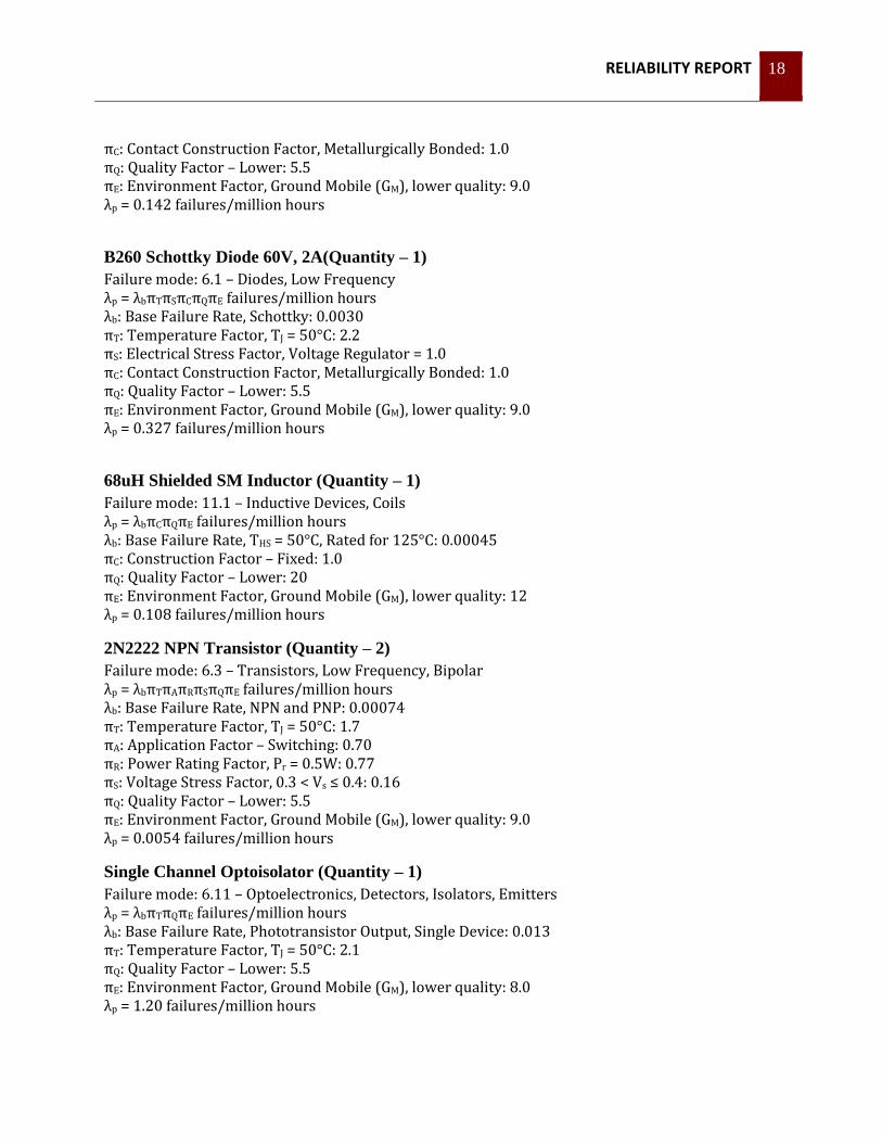
B260 Schottky Diode 60V, 2A(Quantity – 1)
Failure mode: 6.1 – Diodes, Low Frequency λp = λbπTπSπCπQπE failures/million hours λb: Base Failure Rate, Schottky: 0.0030 πT: Temperature Factor, TJ = 50°C: 2.2 πS: Electrical Stress Factor, Voltage Regulator = 1.0 πC: Contact Construction Factor, Metallurgically Bonded: 1.0 πQ: Quality Factor – Lower: 5.5 πE: Environment Factor, Ground Mobile (GM), lower quality: 9.0 λp = 0.327 failures/million hours
68uH Shielded SM Inductor (Quantity – 1)
Failure mode: 11.1 – Inductive Devices, Coils λp = λbπCπQπE failures/million hours λb: Base Failure Rate, THS = 50°C, Rated for 125°C: 0.00045 πC: Construction Factor – Fixed: 1.0 πQ: Quality Factor – Lower: 20 πE: Environment Factor, Ground Mobile (GM), lower quality: 12 λp = 0.108 failures/million hours
2N2222 NPN Transistor (Quantity – 2)
Failure mode: 6.3 – Transistors, Low Frequency, Bipolar λp = λbπTπAπRπSπQπE failures/million hours λb: Base Failure Rate, NPN and PNP: 0.00074 πT: Temperature Factor, TJ = 50°C: 1.7 πA: Application Factor – Switching: 0.70 πR: Power Rating Factor, Pr = 0.5W: 0.77 πS: Voltage Stress Factor, 0.3 < Vs ≤ 0.4: 0.16 πQ: Quality Factor – Lower: 5.5 πE: Environment Factor, Ground Mobile (GM), lower quality: 9.0 λp = 0.0054 failures/million hours
Single Channel Optoisolator (Quantity – 1)
Failure mode: 6.11 – Optoelectronics, Detectors, Isolators, Emitters λp = λbπTπQπE failures/million hours λb: Base Failure Rate, Phototransistor Output, Single Device: 0.013 πT: Temperature Factor, TJ = 50°C: 2.1 πQ: Quality Factor – Lower: 5.5 πE: Environment Factor, Ground Mobile (GM), lower quality: 8.0 λp = 1.20 failures/million hours
RELIABILITY REPORT 19
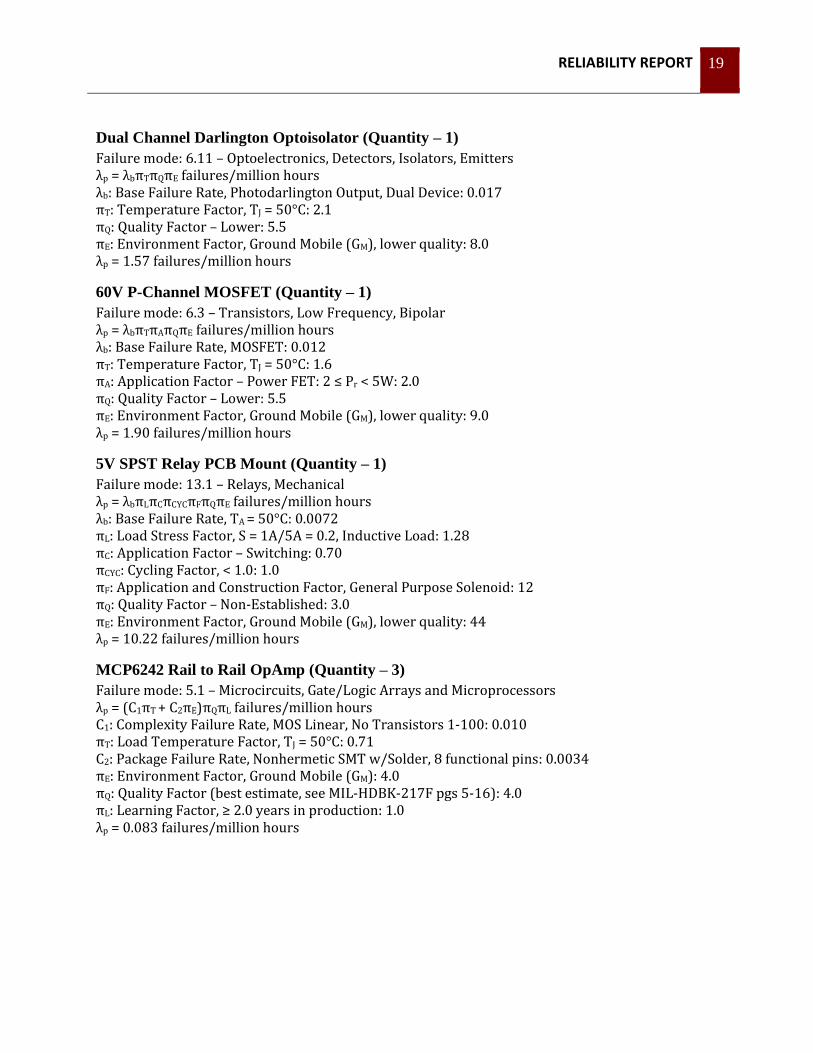
Dual Channel Darlington Optoisolator (Quantity – 1)
Failure mode: 6.11 – Optoelectronics, Detectors, Isolators, Emitters λp = λbπTπQπE failures/million hours λb: Base Failure Rate, Photodarlington Output, Dual Device: 0.017 πT: Temperature Factor, TJ = 50°C: 2.1 πQ: Quality Factor – Lower: 5.5 πE: Environment Factor, Ground Mobile (GM), lower quality: 8.0 λp = 1.57 failures/million hours
60V P-Channel MOSFET (Quantity – 1)
Failure mode: 6.3 – Transistors, Low Frequency, Bipolar λp = λbπTπAπQπE failures/million hours λb: Base Failure Rate, MOSFET: 0.012 πT: Temperature Factor, TJ = 50°C: 1.6 πA: Application Factor – Power FET: 2 ≤ Pr < 5W: 2.0 πQ: Quality Factor – Lower: 5.5 πE: Environment Factor, Ground Mobile (GM), lower quality: 9.0 λp = 1.90 failures/million hours
5V SPST Relay PCB Mount (Quantity – 1)
Failure mode: 13.1 – Relays, Mechanical λp = λbπLπCπCYCπFπQπE failures/million hours λb: Base Failure Rate, TA = 50°C: 0.0072 πL: Load Stress Factor, S = 1A/5A = 0.2, Inductive Load: 1.28 πC: Application Factor – Switching: 0.70 πCYC: Cycling Factor, < 1.0: 1.0 πF: Application and Construction Factor, General Purpose Solenoid: 12 πQ: Quality Factor – Non-Established: 3.0 πE: Environment Factor, Ground Mobile (GM), lower quality: 44 λp = 10.22 failures/million hours
MCP6242 Rail to Rail OpAmp (Quantity – 3)
Failure mode: 5.1 – Microcircuits, Gate/Logic Arrays and Microprocessors λp = (C1πT + C2πE)πQπL failures/million hours C1: Complexity Failure Rate, MOS Linear, No Transistors 1-100: 0.010 πT: Load Temperature Factor, TJ = 50°C: 0.71 C2: Package Failure Rate, Nonhermetic SMT w/Solder, 8 functional pins: 0.0034 πE: Environment Factor, Ground Mobile (GM): 4.0 πQ: Quality Factor (best estimate, see MIL-HDBK-217F pgs 5-16): 4.0 πL: Learning Factor, ≥ 2.0 years in production: 1.0 λp = 0.083 failures/million hours

RELIABILITY REPORT 20
MIC4680 Switching Regulator (Quantity – 1)
Failure mode: 5.1 – Microcircuits, Gate/Logic Arrays and Microprocessors λp = (C1πT + C2πE)πQπL failures/million hours C1: Complexity Failure Rate, MOS Linear, No Transistors 1-100: 0.010 πT: Load Temperature Factor, TJ = 50°C: 0.71 C2: Package Failure Rate, Nonhermetic SMT w/Solder, 8 functional pins: 0.0034 πE: Environment Factor, Ground Mobile (GM): 4.0 πQ: Quality Factor (best estimate, see MIL-HDBK-217F pgs 5-16): 4.0 πL: Learning Factor, ≥ 2.0 years in production: 1.0 λp = 0.083 failures/million hours
ADM1232 Watchdog Timer (Quantity – 1)
Failure mode: 5.1 – Microcircuits, Gate/Logic Arrays and Microprocessors λp = (C1πT + C2πE)πQπL failures/million hours C1: Complexity Failure Rate, MOS Linear, No Transistors 1-100: 0.010 πT: Load Temperature Factor, TJ = 50°C: 0.71 C2: Package Failure Rate, Nonhermetic SMT w/Solder, 8 functional pins: 0.0034 πE: Environment Factor, Ground Mobile (GM): 4.0 πQ: Quality Factor (best estimate, see MIL-HDBK-217F pgs 5-16): 4.0 πL: Learning Factor, ≥ 2.0 years in production: 1.0 λp = 0.083 failures/million hours
ADM2483 Half Duplex RS-485 Isolator (Quantity – 1)
Failure mode: 5.1 – Microcircuits, Gate/Logic Arrays and Microprocessors λp = (C1πT + C2πE)πQπL failures/million hours C1: Complexity Failure Rate, MOS Linear, No Transistors 1-100: 0.010 πT: Load Temperature Factor, TJ = 50°C: 0.71 C2: Package Failure Rate, Nonhermetic SMT w/Solder, 16 functional pins: 0.0072 πE: Environment Factor, Ground Mobile (GM): 4.0 πQ: Quality Factor (best estimate, see MIL-HDBK-217F pgs 5-16): 4.0 πL: Learning Factor, ≥ 2.0 years in production: 1.0 λp = 0.144 failures/million hours
HCT4002D Dual Input NOR Gate (Quantity – 1)
Failure mode: 5.1 – Microcircuits, Gate/Logic Arrays and Microprocessors λp = (C1πT + C2πE)πQπL failures/million hours C1: Complexity Failure Rate, MOS Linear, No Transistors 1-100: 0.010 πT: Load Temperature Factor, TJ = 50°C: 0.71 C2: Package Failure Rate, Nonhermetic SMT w/Solder, 14 functional pins: 0.0062 πE: Environment Factor, Ground Mobile (GM): 4.0 πQ: Quality Factor (best estimate, see MIL-HDBK-217F pgs 5-16): 4.0 πL: Learning Factor, ≥ 2.0 years in production: 1.0 λp = 0.128 failures/million hours

RELIABILITY REPORT 21
M74HC07 Hex Open-Drain Buffer (Quantity – 1)
Failure mode: 5.1 – Microcircuits, Gate/Logic Arrays and Microprocessors λp = (C1πT + C2πE)πQπL failures/million hours C1: Complexity Failure Rate, MOS Linear, No Transistors 1-100: 0.010 πT: Load Temperature Factor, TJ = 50°C: 0.71 C2: Package Failure Rate, Nonhermetic SMT w/Solder, 14 functional pins: 0.0062 πE: Environment Factor, Ground Mobile (GM): 4.0 πQ: Quality Factor (best estimate, see MIL-HDBK-217F pgs 5-16): 4.0 πL: Learning Factor, ≥ 2.0 years in production: 1.0 λp = 0.128 failures/million hours
LTC4151 High Voltage I2C Current and Voltage Monitor (Quantity – 2)
Failure mode: 5.1 – Microcircuits, Gate/Logic Arrays and Microprocessors λp = (C1πT + C2πE)πQπL failures/million hours C1: Complexity Failure Rate, MOS Linear, No Transistors 1-100: 0.010 πT: Load Temperature Factor, TJ = 50°C: 0.71 C2: Package Failure Rate, Nonhermetic SMT w/Solder, 16 functional pins: 0.0072 πE: Environment Factor, Ground Mobile (GM): 4.0 πQ: Quality Factor (best estimate, see MIL-HDBK-217F pgs 5-16): 4.0 πL: Learning Factor, ≥ 2.0 years in production: 1.0 λp = 0.144 failures/million hours
RELIABILITY REPORT 22
Appendix C: AMS Board Detailed
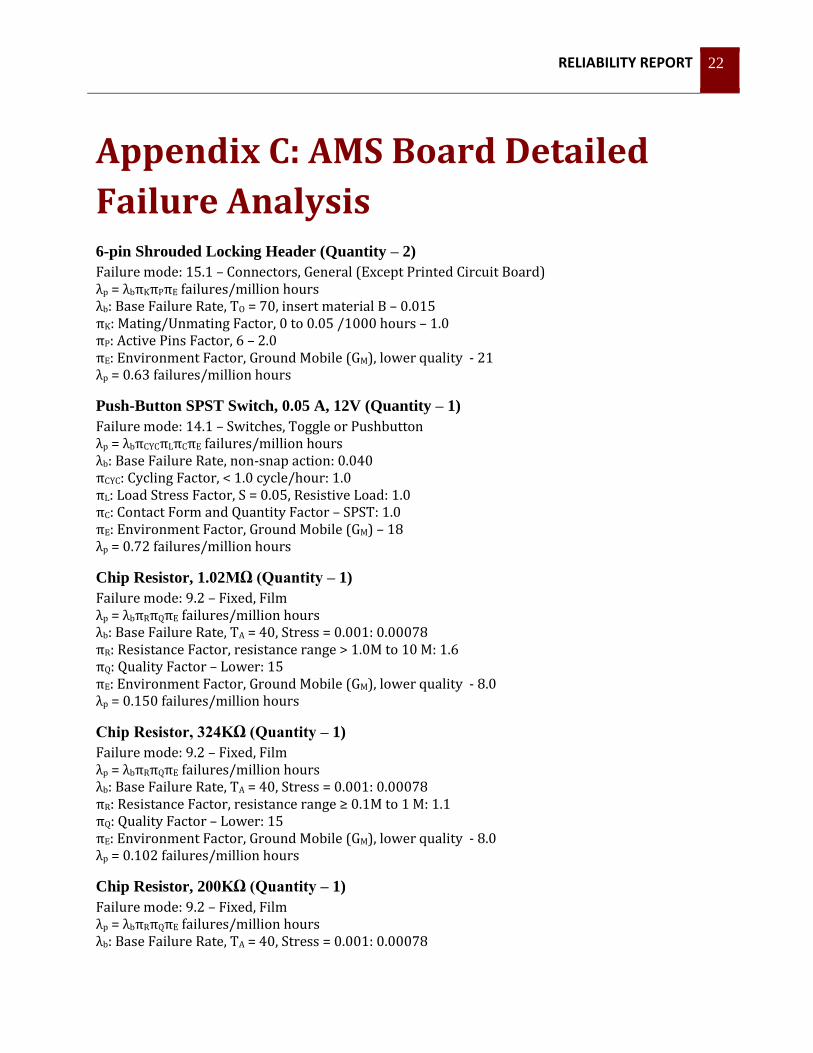
Failure Analysis 6-pin Shrouded Locking Header (Quantity – 2)
Failure mode: 15.1 – Connectors, General (Except Printed Circuit Board) λp = λbπKπPπE failures/million hours λb: Base Failure Rate, TO = 70, insert material B – 0.015 πK: Mating/Unmating Factor, 0 to 0.05 /1000 hours – 1.0 πP: Active Pins Factor, 6 – 2.0 πE: Environment Factor, Ground Mobile (GM), lower quality - 21 λp = 0.63 failures/million hours
Push-Button SPST Switch, 0.05 A, 12V (Quantity – 1)
Failure mode: 14.1 – Switches, Toggle or Pushbutton λp = λbπCYCπLπCπE failures/million hours λb: Base Failure Rate, non-snap action: 0.040 πCYC: Cycling Factor, < 1.0 cycle/hour: 1.0 πL: Load Stress Factor, S = 0.05, Resistive Load: 1.0 πC: Contact Form and Quantity Factor – SPST: 1.0 πE: Environment Factor, Ground Mobile (GM) – 18 λp = 0.72 failures/million hours
Chip Resistor, 1.02MΩ (Quantity – 1)
Failure mode: 9.2 – Fixed, Film λp = λbπRπQπE failures/million hours λb: Base Failure Rate, TA = 40, Stress = 0.001: 0.00078 πR: Resistance Factor, resistance range > 1.0M to 10 M: 1.6 πQ: Quality Factor – Lower: 15 πE: Environment Factor, Ground Mobile (GM), lower quality - 8.0 λp = 0.150 failures/million hours
Chip Resistor, 324KΩ (Quantity – 1)
Failure mode: 9.2 – Fixed, Film λp = λbπRπQπE failures/million hours λb: Base Failure Rate, TA = 40, Stress = 0.001: 0.00078 πR: Resistance Factor, resistance range ≥ 0.1M to 1 M: 1.1 πQ: Quality Factor – Lower: 15 πE: Environment Factor, Ground Mobile (GM), lower quality - 8.0 λp = 0.102 failures/million hours
Chip Resistor, 200KΩ (Quantity – 1)
Failure mode: 9.2 – Fixed, Film λp = λbπRπQπE failures/million hours λb: Base Failure Rate, TA = 40, Stress = 0.001: 0.00078

RELIABILITY REPORT 23
πR: Resistance Factor, resistance range ≥ 0.1M to 1 M: 1.1 πQ: Quality Factor – Lower: 15 πE: Environment Factor, Ground Mobile (GM), lower quality - 8.0 λp = 0.102 failures/million hours
Chip Resistor, 100KΩ (Quantity – 2)
Failure mode: 9.2 – Fixed, Film λp = λbπRπQπE failures/million hours λb: Base Failure Rate, TA = 40, Stress = 0.001: 0.00078 πR: Resistance Factor, resistance range ≥ 0.1M to 1 M: 1.1 πQ: Quality Factor – Lower: 15 πE: Environment Factor, Ground Mobile (GM), lower quality - 8.0 λp = 0.102 failures/million hours
Chip Resistor, 10KΩ (Quantity – 3)
Failure mode: 9.2 – Fixed, Film λp = λbπRπQπE failures/million hours λb: Base Failure Rate, TA = 40, Stress = 0.001: 0.00078 πR: Resistance Factor, resistance range < 0.1 M: 1.0 πQ: Quality Factor – Lower: 15 πE: Environment Factor, Ground Mobile (GM), lower quality - 8.0 λp = 0.094 failures/million hours
Chip Resistor, 470Ω (Quantity – 1)
Failure mode: 9.2 – Fixed, Film λp = λbπRπQπE failures/million hours λb: Base Failure Rate, TA = 40, Stress = 0.001: 0.00078 πR: Resistance Factor, resistance range < 0.1 M: 1.0 πQ: Quality Factor – Lower: 15 πE: Environment Factor, Ground Mobile (GM), lower quality - 8.0 λp = 0.094 failures/million hours
Chip Resistor, 383Ω (Quantity – 1)
Failure mode: 9.2 – Fixed, Film λp = λbπRπQπE failures/million hours λb: Base Failure Rate, TA = 40, Stress = 0.001: 0.00078 πR: Resistance Factor, resistance range < 0.1 M: 1.0 πQ: Quality Factor – Lower: 15 πE: Environment Factor, Ground Mobile (GM), lower quality - 8.0 λp = 0.094 failures/million hours
Chip Resistor, 200Ω (Quantity – 1)
Failure mode: 9.2 – Fixed, Film λp = λbπRπQπE failures/million hours λb: Base Failure Rate, TA = 40, Stress = 0.001: 0.00078 πR: Resistance Factor, resistance range < 0.1 M: 1.0 πQ: Quality Factor – Lower: 15 πE: Environment Factor, Ground Mobile (GM), lower quality - 8.0

RELIABILITY REPORT 24
λp = 0.094 failures/million hours
Chip Resistor, 100Ω (Quantity – 1)
Failure mode: 9.2 – Fixed, Film λp = λbπRπQπE failures/million hours λb: Base Failure Rate, TA = 40, Stress = 0.001: 0.00078 πR: Resistance Factor, resistance range < 0.1 M: 1.0 πQ: Quality Factor – Lower: 15 πE: Environment Factor, Ground Mobile (GM), lower quality - 8.0 λp = 0.094 failures/million hours
Chip Resistor, 36Ω (Quantity – 1)
Failure mode: 9.2 – Fixed, Film λp = λbπRπQπE failures/million hours λb: Base Failure Rate, TA = 40, Stress = 0.001: 0.00078 πR: Resistance Factor, resistance range < 0.1 M: 1.0 πQ: Quality Factor – Lower: 15 πE: Environment Factor, Ground Mobile (GM), lower quality - 8.0 λp = 0.094 failures/million hours
Power Resistor, 0.75Ω, 20W (Quantity – 1)
Failure mode: 9.3 – Fixed, Film, Power λp = λbπRπQπE failures/million hours λb: Base Failure Rate, TA = 40, Stress = 7.2W/20W: 0.14 πR: Resistance Factor, resistance range 10-100Ω: 1.0 πQ: Quality Factor – Lower: 3.0 πE: Environment Factor, Ground Mobile (GM), lower quality - 10 λp = 4.2 failures/million hours
Ceramic Chip Capacitor, 680pF (Quantity – 1)
Failure mode: 10.10 – Capacitors, Fixed, Ceramic, General Purpose λp = λbπCVπQπE failures/million hours λb: Base Failure Rate, TA = 50°C, 125°C rating, Stress = 0.001: 0.00070 πCV: Capacitance Factor, C is in pF, (0.41)C0.11 = 0.84 πQ: Quality Factor – Lower: 10 πE: Environment Factor, Ground Mobile (GM), lower quality - 9.0 λp = 0.053 failures/million hours
Ceramic Chip Capacitor, 0.1uF (Quantity – 5)
Failure mode: 10.10 – Capacitors, Fixed, Ceramic, General Purpose λp = λbπCVπQπE failures/million hours λb: Base Failure Rate, TA = 50°C, 125°C rating, Stress = 0.001: 0.00070 πCV: Capacitance Factor, C is in pF, (0.41)C0.11 = 1.45 πQ: Quality Factor – Lower: 10 πE: Environment Factor, Ground Mobile (GM), lower quality - 9.0 λp = 0.091 failures/million hours
RELIABILITY REPORT 25
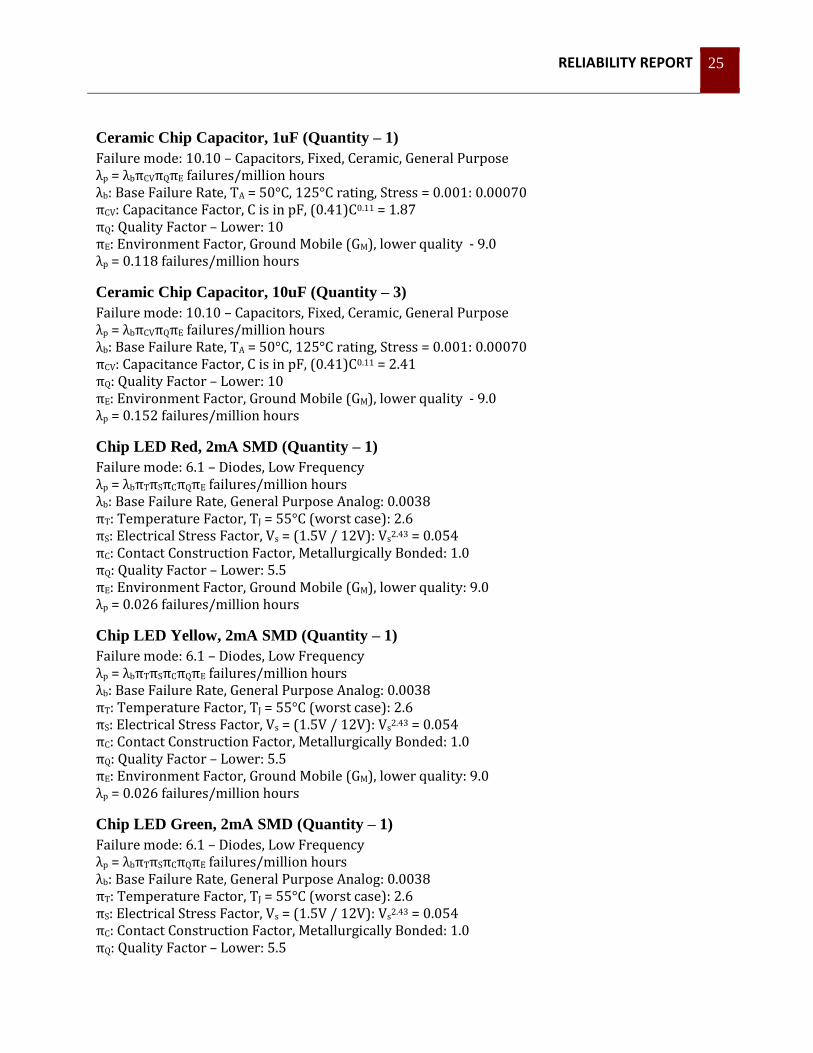
Ceramic Chip Capacitor, 1uF (Quantity – 1)
Failure mode: 10.10 – Capacitors, Fixed, Ceramic, General Purpose λp = λbπCVπQπE failures/million hours λb: Base Failure Rate, TA = 50°C, 125°C rating, Stress = 0.001: 0.00070 πCV: Capacitance Factor, C is in pF, (0.41)C0.11 = 1.87 πQ: Quality Factor – Lower: 10 πE: Environment Factor, Ground Mobile (GM), lower quality - 9.0 λp = 0.118 failures/million hours
Ceramic Chip Capacitor, 10uF (Quantity – 3)
Failure mode: 10.10 – Capacitors, Fixed, Ceramic, General Purpose λp = λbπCVπQπE failures/million hours λb: Base Failure Rate, TA = 50°C, 125°C rating, Stress = 0.001: 0.00070 πCV: Capacitance Factor, C is in pF, (0.41)C0.11 = 2.41 πQ: Quality Factor – Lower: 10 πE: Environment Factor, Ground Mobile (GM), lower quality - 9.0 λp = 0.152 failures/million hours
Chip LED Red, 2mA SMD (Quantity – 1)
Failure mode: 6.1 – Diodes, Low Frequency λp = λbπTπSπCπQπE failures/million hours λb: Base Failure Rate, General Purpose Analog: 0.0038 πT: Temperature Factor, TJ = 55°C (worst case): 2.6 πS: Electrical Stress Factor, Vs = (1.5V / 12V): Vs2.43 = 0.054 πC: Contact Construction Factor, Metallurgically Bonded: 1.0 πQ: Quality Factor – Lower: 5.5 πE: Environment Factor, Ground Mobile (GM), lower quality: 9.0 λp = 0.026 failures/million hours
Chip LED Yellow, 2mA SMD (Quantity – 1)
Failure mode: 6.1 – Diodes, Low Frequency λp = λbπTπSπCπQπE failures/million hours λb: Base Failure Rate, General Purpose Analog: 0.0038 πT: Temperature Factor, TJ = 55°C (worst case): 2.6 πS: Electrical Stress Factor, Vs = (1.5V / 12V): Vs2.43 = 0.054 πC: Contact Construction Factor, Metallurgically Bonded: 1.0 πQ: Quality Factor – Lower: 5.5 πE: Environment Factor, Ground Mobile (GM), lower quality: 9.0 λp = 0.026 failures/million hours
Chip LED Green, 2mA SMD (Quantity – 1)
Failure mode: 6.1 – Diodes, Low Frequency λp = λbπTπSπCπQπE failures/million hours λb: Base Failure Rate, General Purpose Analog: 0.0038 πT: Temperature Factor, TJ = 55°C (worst case): 2.6 πS: Electrical Stress Factor, Vs = (1.5V / 12V): Vs2.43 = 0.054 πC: Contact Construction Factor, Metallurgically Bonded: 1.0 πQ: Quality Factor – Lower: 5.5
RELIABILITY REPORT 26
πE: Environment Factor, Ground Mobile (GM), lower quality: 9.0 λp = 0.026 failures/million hours
Schottky Diode 20VDC, 500mA (Quantity – 1)
Failure mode: 6.1 – Diodes, Low Frequency λp = λbπTπSπCπQπE failures/million hours λb: Base Failure Rate, Schottky: 0.0030 πT: Temperature Factor, TJ = 52°C: 2.3 πS: Electrical Stress Factor, Voltage Regulator = 1.0 πC: Contact Construction Factor, Metallurgically Bonded: 1.0 πQ: Quality Factor – Lower: 5.5 πE: Environment Factor, Ground Mobile (GM), lower quality: 9.0 λp = 0.342 failures/million hours
10uH Semi-Shielded SM Inductor (Quantity – 1)
Failure mode: 11.1 – Inductive Devices, Coils λp = λbπCπQπE failures/million hours λb: Base Failure Rate, THS = 50°C, Rated for 125°C: 0.00045 πC: Construction Factor – Fixed: 1.0 πQ: Quality Factor – Lower: 20 πE: Environment Factor, Ground Mobile (GM), lower quality: 12 λp = 0.108 failures/million hours
TIP102 Darlington NPN Power Transistor (Quantity – 1)
Failure mode: 6.3 – Transistors, Low Frequency, Bipolar λp = λbπTπAπRπSπQπE failures/million hours λb: Base Failure Rate, NPN and PNP: 0.00074 πT: Temperature Factor, TJ = 77°C: 2.9 πA: Application Factor – Switching: 0.70 πR: Power Rating Factor, Pr = 1W: 1.0 πS: Voltage Stress Factor, Vs < 0.3: 0.11 πQ: Quality Factor – Lower: 5.5 πE: Environment Factor, Ground Mobile (GM), lower quality: 9.0 λp = 0.0074 failures/million hours
LTV-357T Single Channel Optoisolator (Quantity – 1)
Failure mode: 6.11 – Optoelectronics, Detectors, Isolators, Emitters λp = λbπTπQπE failures/million hours λb: Base Failure Rate, Phototransistor Output, Single Device: 0.013 πT: Temperature Factor, TJ = 50°C: 2.1 πQ: Quality Factor – Lower: 5.5 πE: Environment Factor, Ground Mobile (GM), lower quality: 8.0 λp = 1.20 failures/million hours
PIC16(L)F1826/27 (Quantity – 1)
Failure mode: 5.1 – Microcircuits, Gate/Logic Arrays and Microprocessors λp = (C1πT + C2πE)πQπL failures/million hours C1: Microprocessor Die Complexity Failure Rate, 16 bits, MOS – 0.010
RELIABILITY REPORT 27
πT: Load Temperature Factor, Digital MOS/VHSIC CMOS, TJ = 50°C: 0.29 C2: Package Failure Rate, Nonhermetic SMT w/Solder, 18 functional pins: 0.0082 πE: Environment Factor, Ground Mobile (GM): 4.0 πQ: Quality Factor (best estimate, see MIL-HDBK-217F pgs 5-16): 4.0 πL: Learning Factor, ≥ 2.0 years in production: 1.0 λp = 0.143 failures/million hours
MCP6242 Rail to Rail OpAmp (Quantity – 1)
Failure mode: 5.1 – Microcircuits, Gate/Logic Arrays and Microprocessors λp = (C1πT + C2πE)πQπL failures/million hours C1: Complexity Failure Rate, MOS Linear, No Transistors 1-100: 0.010 πT: Load Temperature Factor, TJ = 50°C: 0.71 C2: Package Failure Rate, Nonhermetic SMT w/Solder, 8 functional pins: 0.0034 πE: Environment Factor, Ground Mobile (GM): 4.0 πQ: Quality Factor (best estimate, see MIL-HDBK-217F pgs 5-16): 4.0 πL: Learning Factor, ≥ 2.0 years in production: 1.0 λp = 0.083 failures/million hours
LT1307 DC-DC Switching Regulator (Quantity – 1)
Failure mode: 5.1 – Microcircuits, Gate/Logic Arrays and Microprocessors λp = (C1πT + C2πE)πQπL failures/million hours C1: Complexity Failure Rate, MOS Linear, No Transistors 1-100: 0.010 πT: Load Temperature Factor, TJ = 50°C: 0.71 C2: Package Failure Rate, Nonhermetic SMT w/Solder, 8 functional pins: 0.0034 πE: Environment Factor, Ground Mobile (GM): 4.0 πQ: Quality Factor (best estimate, see MIL-HDBK-217F pgs 5-16): 4.0 πL: Learning Factor, ≥ 2.0 years in production: 1.0 λp = 0.083 failures/million hours
MCP9700 Linear Thermistor Temp Sensor SOT-23-3 (Quantity – 1)
Failure mode: 5.1 – Microcircuits, Gate/Logic Arrays and Microprocessors λp = (C1πT + C2πE)πQπL failures/million hours C1: Complexity Failure Rate, MOS Linear, No Transistors 1-100: 0.010 πT: Load Temperature Factor, TJ = 50°C: 0.71 C2: Package Failure Rate, Nonhermetic SMT w/Solder, 3 functional pins: 0.0012 πE: Environment Factor, Ground Mobile (GM): 4.0 πQ: Quality Factor (best estimate, see MIL-HDBK-217F pgs 5-16): 4.0 πL: Learning Factor, ≥ 2.0 years in production: 1.0 λp = 0.048 failures/million hours
3.3V LDO Voltage Regulator 500mA (Quantity – 1)
Failure mode: 5.1 – Microcircuits, Gate/Logic Arrays and Microprocessors λp = (C1πT + C2πE)πQπL failures/million hours C1: Complexity Failure Rate, MOS Linear, No Transistors 1-100: 0.010 πT: Load Temperature Factor, TJ = 50°C: 0.71 C2: Package Failure Rate, Nonhermetic SMT w/Solder, 3 functional pins: 0.0012 πE: Environment Factor, Ground Mobile (GM): 4.0

RELIABILITY REPORT 28
πQ: Quality Factor (best estimate, see MIL-HDBK-217F pgs 5-16): 4.0 πL: Learning Factor, ≥ 2.0 years in production: 1.0 λp = 0.048 failures/million hours
Dual I2C Isolator (Quantity – 1)
Failure mode: 5.1 – Microcircuits, Gate/Logic Arrays and Microprocessors λp = (C1πT + C2πE)πQπL failures/million hours C1: Complexity Failure Rate, MOS Linear, No Transistors 1-100: 0.010 πT: Load Temperature Factor, TJ = 50°C: 0.71 C2: Package Failure Rate, Nonhermetic SMT w/Solder, 8 functional pins: 0.0034 πE: Environment Factor, Ground Mobile (GM): 4.0 πQ: Quality Factor (best estimate, see MIL-HDBK-217F pgs 5-16): 4.0 πL: Learning Factor, ≥ 2.0 years in production: 1.0 λp = 0.083 failures/million hours

RELIABILITY REPORT 29
Appendix D: Charger Detailed
Failure Analysis TDK-Lambda GENH30-25 Power Supply (Quantity – 1)
5-year warranty provided by manufacturer. With worst case scenario of MTBF = 5 years. λp = 22.8 failures/million hours
Charger Anderson Connector Plug (Quantity – 3)
Failure mode: 15.1 – Connectors, General (Except Printed Circuit Board) λp = λbπKπPπE failures/million hours λb: Base Failure Rate, TO = 70, insert material B – 0.015 πK: Mating/Unmating Factor, >50 times /1000 hours – 4.0 πP: Active Pins Factor, 6 – 2.0 πE: Environment Factor, Ground Mobile (GM), lower quality - 21 λp = 2.52 failures/million hours