release analysis: impact of aircraft wheel flange fragment ... · Rim release analysis: impact of...
10
Rim release analysis: impact of aircraft wheel flange fragment on wing flap mechanism S. Heimbs, H. Lang & T. Havar EADS Innovation Works, Munich, Germany Abstract This paper describes the numerical investigation of the mechanical behaviour of a structural component of an aircraft wing flap support impacted by a wheel rim fragment. A simulation model of the support link made of composite materials was developed, incorporating intralaminar and interlaminar failure modes. Validation studies were performed using quasi-static and low velocity impact test data. Finally, high velocity impact simulations with a metallic rim fragment were performed for several load cases involving different angles, impactor rotation and pre-stress. Keywords: high velocity impact, composites, flap support, rim release, FEM. 1 Introduction Composite materials allow for significant weight savings in aeronautical structures due to their high weight-specific stiffness and strength properties. Therefore, more and more classical metallic aircraft parts are replaced by lighter and often cheaper composite parts. One example, which is the focus of this paper, is the linkage system of the aircraft wing flap mechanism (Fig. 1). Figure 1: Illustration of linkage system of wing flap at Airbus A340. rear link flap fragment Structures Under Shock and Impact XII 193 www.witpress.com, ISSN 1743-3509 (on-line) WIT Transactions on The Built Environment, Vol 126, © 201 WIT Press 2 doi:10.2495/SU120171
Transcript of release analysis: impact of aircraft wheel flange fragment ... · Rim release analysis: impact of...
Rim release analysis: impact of aircraft wheel flange fragment on wing flap mechanism
S. Heimbs, H. Lang & T. Havar EADS Innovation Works, Munich, Germany
Abstract
This paper describes the numerical investigation of the mechanical behaviour of a structural component of an aircraft wing flap support impacted by a wheel rim fragment. A simulation model of the support link made of composite materials was developed, incorporating intralaminar and interlaminar failure modes. Validation studies were performed using quasi-static and low velocity impact test data. Finally, high velocity impact simulations with a metallic rim fragment were performed for several load cases involving different angles, impactor rotation and pre-stress. Keywords: high velocity impact, composites, flap support, rim release, FEM.
1 Introduction
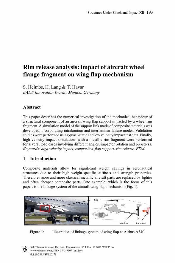
Composite materials allow for significant weight savings in aeronautical structures due to their high weight-specific stiffness and strength properties. Therefore, more and more classical metallic aircraft parts are replaced by lighter and often cheaper composite parts. One example, which is the focus of this paper, is the linkage system of the aircraft wing flap mechanism (Fig. 1).
Figure 1: Illustration of linkage system of wing flap at Airbus A340.
rear link
flap
fragment
Structures Under Shock and Impact XII 193
www.witpress.com, ISSN 1743-3509 (on-line) WIT Transactions on The Built Environment, Vol 126, © 201 WIT Press2
doi:10.2495/SU120171
The rear link is typically built as a massive metallic component. In recent years, innovative concepts of a rear link made of composite materials have been developed to replace the existing metallic solution for weight and cost saving reasons [1, 2]. Such a linkage structure is primarily designed for different quasi-static load cases related to different wing flap positions. However, one important dynamic load case is also relevant: the impact of a wheel rim fragment after fracture of the aircraft wheel during take-off or landing, referred to as ‘rim release’. Aircraft wheels are typically made from forged aluminium alloy. During service they are exposed to harsh operating conditions, like high take-off and landing loads, high-energy and high-temperature braking events or corrosion from runway and aircraft fluids. The main cause of rim fracture is high-cycle fatigue loading with the weakest area at the flange of the wheels. When wheel failure occurs, the fragments are often propelled with high energy. Some examples are documented in the literature, e.g. the wheel failure of a Piaggio P180 business aircraft with the bursting wheel flange fragment being thrown against the landing gear door [3]. Further examples of other aircraft can be found in [4–8]. Rim release investigations are typically conducted experimentally, by shooting defined fragment impactors on the structural components with a gas gun. As such tests are both time- and cost-consuming for new design concepts in terms of prototype manufacturing, testing efforts and damage inspection, today’s trend is more and more to use virtual tests performed with dynamic finite element (FE) simulations to reduce the amount of real experiments to a minimum. This paper describes the approach of simulating the high velocity impact of a metallic wheel flange fragment on a conceptual composite rear link of the wing flap support using the commercial FE code Abaqus/Explicit.
2 Composite linkage bar – materials and manufacturing
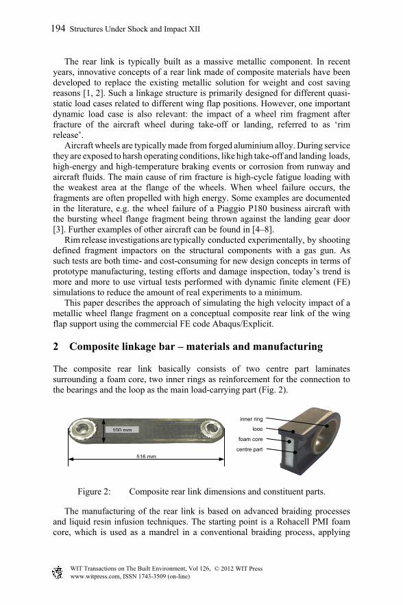
The composite rear link basically consists of two centre part laminates surrounding a foam core, two inner rings as reinforcement for the connection to the bearings and the loop as the main load-carrying part (Fig. 2).
Figure 2: Composite rear link dimensions and constituent parts.
The manufacturing of the rear link is based on advanced braiding processes and liquid resin infusion techniques. The starting point is a Rohacell PMI foam core, which is used as a mandrel in a conventional braiding process, applying
foam core
inner ring
loop
centre part516 mm
100 mm
194 Structures Under Shock and Impact XII
www.witpress.com, ISSN 1743-3509 (on-line) WIT Transactions on The Built Environment, Vol 126, © 201 WIT Press2
±45° textile reinforcement layers of carbon fibres. Additional 0° reinforcement layers are applied on the side walls after each braiding step. This procedure is repeated until the specified thickness of the centre part is reached. On both ends of this part a radius is cut for the connection of the inner rings, using an ultrasonic cutting machine. The 2 mm thick E-glass fibre-reinforced inner rings are a ±45° braided textile as well. The loop is braided around the centre part and the two inner rings using a unidirectional braiding process [9]. The loop was built up from 30 unidirectional braided layers with a final thickness of 12 mm. The resulting preform of the rear link is infiltrated with epoxy resin in a vacuum-assisted process and cured at 180°C. After machining of the cured rear link, the bearings are fitted under low temperatures (Fig. 2).
3 Finite element model development and validation
3.1 Rear link model
Geometry and meshing: The composite linkage model consists of four major parts: the loop, the centre part, the foam core and the inner rings. All parts were created as 3D bodies in the commercial FE-software Abaqus. The Rohacell foam core was meshed with 8-node solid elements (C3D8), using the ‘Crushable-Foam’ material model. All composite parts were meshed with 8-node continuum shell elements (SC8R). The inner rings were attached to the surrounding parts and the centre part was attached to the loop by tie constraints. A general contact was defined, which prevents any part of penetrating another part.
Composite material model: Different damage mechanisms can occur in composite laminates under impact loading that can often be identified as matrix cracking, delaminations and finally fibre rupture. It is desired that all these potential failure modes are covered by the numerical model enabling their occurrence in the simulation as well. In the current study, the default composite material model in Abaqus was used, which is based on an orthotropic linear elastic formulation and Hashin failure criteria for damage initiation. Damage evolution until complete erosion of the ply is controlled by fracture energies in fibre and matrix direction for compression and tension with a linear stiffness degradation.
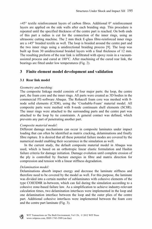
Delamination model: Delaminations absorb impact energy and decrease the laminate stiffness and therefore need to be covered by the model as well. For this purpose, the laminate was divided into a certain number of sublaminates with cohesive elements of the type COH3D8R in-between, which can fail during the simulation according to a cohesive zone-based failure law. As a simplification to achieve industry-relevant calculation times, two delamination interfaces were implemented in the loop and one delamination interface between the loop and the outer plies of the centre part. Additional cohesive interfaces were implemented between the foam core and the centre part laminate (Fig. 3).
Structures Under Shock and Impact XII 195
www.witpress.com, ISSN 1743-3509 (on-line) WIT Transactions on The Built Environment, Vol 126, © 201 WIT Press2
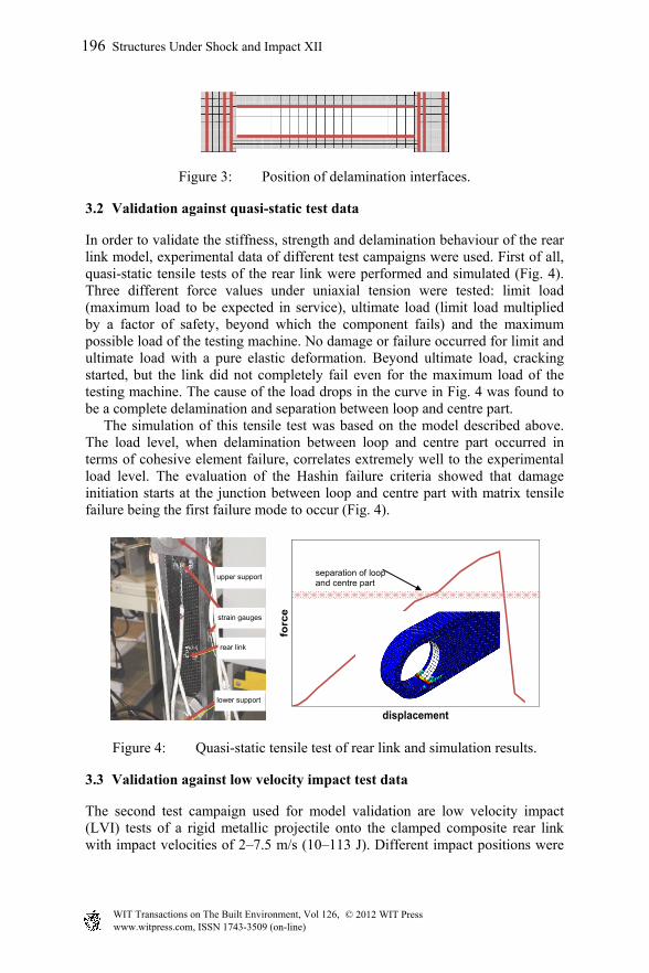
Figure 3: Position of delamination interfaces.
3.2 Validation against quasi-static test data
In order to validate the stiffness, strength and delamination behaviour of the rear link model, experimental data of different test campaigns were used. First of all, quasi-static tensile tests of the rear link were performed and simulated (Fig. 4). Three different force values under uniaxial tension were tested: limit load (maximum load to be expected in service), ultimate load (limit load multiplied by a factor of safety, beyond which the component fails) and the maximum possible load of the testing machine. No damage or failure occurred for limit and ultimate load with a pure elastic deformation. Beyond ultimate load, cracking started, but the link did not completely fail even for the maximum load of the testing machine. The cause of the load drops in the curve in Fig. 4 was found to be a complete delamination and separation between loop and centre part. The simulation of this tensile test was based on the model described above. The load level, when delamination between loop and centre part occurred in terms of cohesive element failure, correlates extremely well to the experimental load level. The evaluation of the Hashin failure criteria showed that damage initiation starts at the junction between loop and centre part with matrix tensile failure being the first failure mode to occur (Fig. 4).
Figure 4: Quasi-static tensile test of rear link and simulation results.
3.3 Validation against low velocity impact test data
The second test campaign used for model validation are low velocity impact (LVI) tests of a rigid metallic projectile onto the clamped composite rear link with impact velocities of 2–7.5 m/s (10–113 J). Different impact positions were
0
100
200
300
400
500
600
700
0 0,5 1 1,5 2 2,5 3 3,5 4 4,5 5
forc
e
displacement
separation of loop and centre part
strain gauges
rear link
upper support
lower support
196 Structures Under Shock and Impact XII
www.witpress.com, ISSN 1743-3509 (on-line) WIT Transactions on The Built Environment, Vol 126, © 201 WIT Press2
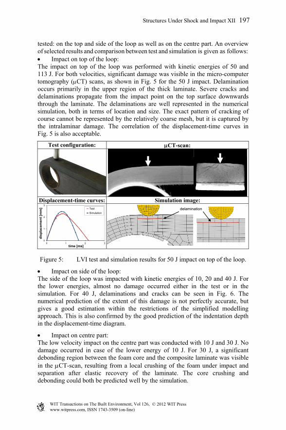
tested: on the top and side of the loop as well as on the centre part. An overview of selected results and comparison between test and simulation is given as follows: Impact on top of the loop: The impact on top of the loop was performed with kinetic energies of 50 and 113 J. For both velocities, significant damage was visible in the micro-computer tomography (CT) scans, as shown in Fig. 5 for the 50 J impact. Delamination occurs primarily in the upper region of the thick laminate. Severe cracks and delaminations propagate from the impact point on the top surface downwards through the laminate. The delaminations are well represented in the numerical simulation, both in terms of location and size. The exact pattern of cracking of course cannot be represented by the relatively coarse mesh, but it is captured by the intralaminar damage. The correlation of the displacement-time curves in Fig. 5 is also acceptable.
Test configuration: CT-scan:
Displacement-time curves: Simulation image:
0
1
2
3
0 1 2 3
dis
pla
cem
en
t [m
m]
time [ms]
Test
Simulation
Figure 5: LVI test and simulation results for 50 J impact on top of the loop.
Impact on side of the loop: The side of the loop was impacted with kinetic energies of 10, 20 and 40 J. For the lower energies, almost no damage occurred either in the test or in the simulation. For 40 J, delaminations and cracks can be seen in Fig. 6. The numerical prediction of the extent of this damage is not perfectly accurate, but gives a good estimation within the restrictions of the simplified modelling approach. This is also confirmed by the good prediction of the indentation depth in the displacement-time diagram.
Impact on centre part: The low velocity impact on the centre part was conducted with 10 J and 30 J. No damage occurred in case of the lower energy of 10 J. For 30 J, a significant debonding region between the foam core and the composite laminate was visible in the CT-scan, resulting from a local crushing of the foam under impact and separation after elastic recovery of the laminate. The core crushing and debonding could both be predicted well by the simulation.
delamination
Structures Under Shock and Impact XII 197
www.witpress.com, ISSN 1743-3509 (on-line) WIT Transactions on The Built Environment, Vol 126, © 201 WIT Press2
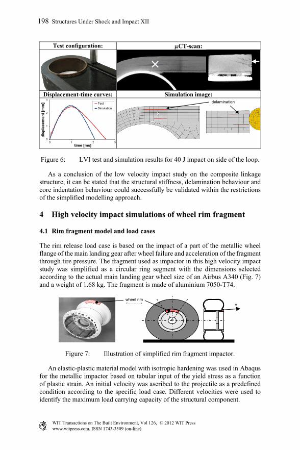
Test configuration: CT-scan:
Displacement-time curves: Simulation image:
0
1
2
3
0 1 2 3
dis
pla
cem
ent
[mm
]
time [ms]
Test
Simulation
Figure 6: LVI test and simulation results for 40 J impact on side of the loop.
As a conclusion of the low velocity impact study on the composite linkage structure, it can be stated that the structural stiffness, delamination behaviour and core indentation behaviour could successfully be validated within the restrictions of the simplified modelling approach.
4 High velocity impact simulations of wheel rim fragment
4.1 Rim fragment model and load cases
The rim release load case is based on the impact of a part of the metallic wheel flange of the main landing gear after wheel failure and acceleration of the fragment through tire pressure. The fragment used as impactor in this high velocity impact study was simplified as a circular ring segment with the dimensions selected according to the actual main landing gear wheel size of an Airbus A340 (Fig. 7) and a weight of 1.68 kg. The fragment is made of aluminium 7050-T74.
Figure 7: Illustration of simplified rim fragment impactor.
An elastic-plastic material model with isotropic hardening was used in Abaqus for the metallic impactor based on tabular input of the yield stress as a function of plastic strain. An initial velocity was ascribed to the projectile as a predefined condition according to the specific load case. Different velocities were used to identify the maximum load carrying capacity of the structural component.
v wheel rim fragment
delamination
198 Structures Under Shock and Impact XII
www.witpress.com, ISSN 1743-3509 (on-line) WIT Transactions on The Built Environment, Vol 126, © 201 WIT Press2
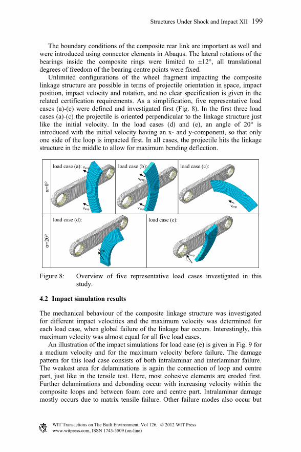
The boundary conditions of the composite rear link are important as well and were introduced using connector elements in Abaqus. The lateral rotations of the bearings inside the composite rings were limited to ±12°, all translational degrees of freedom of the bearing centre points were fixed. Unlimited configurations of the wheel fragment impacting the composite linkage structure are possible in terms of projectile orientation in space, impact position, impact velocity and rotation, and no clear specification is given in the related certification requirements. As a simplification, five representative load cases (a)-(e) were defined and investigated first (Fig. 8). In the first three load cases (a)-(c) the projectile is oriented perpendicular to the linkage structure just like the initial velocity. In the load cases (d) and (e), an angle of 20° is introduced with the initial velocity having an x- and y-component, so that only one side of the loop is impacted first. In all cases, the projectile hits the linkage structure in the middle to allow for maximum bending deflection.
α=0°
α=
20°
Figure 8: Overview of five representative load cases investigated in this study.
4.2 Impact simulation results
The mechanical behaviour of the composite linkage structure was investigated for different impact velocities and the maximum velocity was determined for each load case, when global failure of the linkage bar occurs. Interestingly, this maximum velocity was almost equal for all five load cases. An illustration of the impact simulations for load case (e) is given in Fig. 9 for a medium velocity and for the maximum velocity before failure. The damage pattern for this load case consists of both intralaminar and interlaminar failure. The weakest area for delaminations is again the connection of loop and centre part, just like in the tensile test. Here, most cohesive elements are eroded first. Further delaminations and debonding occur with increasing velocity within the composite loops and between foam core and centre part. Intralaminar damage mostly occurs due to matrix tensile failure. Other failure modes also occur but
load case (a): load case (b): load case (c):
load case (d): load case (e):
vimp
vimp
vimp
vimp
vimp
vimp vimp
Structures Under Shock and Impact XII 199
www.witpress.com, ISSN 1743-3509 (on-line) WIT Transactions on The Built Environment, Vol 126, © 201 WIT Press2
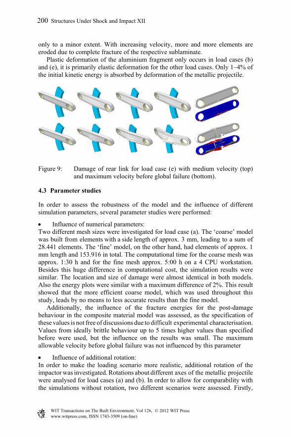
only to a minor extent. With increasing velocity, more and more elements are eroded due to complete fracture of the respective sublaminate. Plastic deformation of the aluminium fragment only occurs in load cases (b) and (e), it is primarily elastic deformation for the other load cases. Only 1–4% of the initial kinetic energy is absorbed by deformation of the metallic projectile.
Figure 9: Damage of rear link for load case (e) with medium velocity (top) and maximum velocity before global failure (bottom).
4.3 Parameter studies
In order to assess the robustness of the model and the influence of different simulation parameters, several parameter studies were performed:
Influence of numerical parameters: Two different mesh sizes were investigated for load case (a). The ‘coarse’ model was built from elements with a side length of approx. 3 mm, leading to a sum of 28.441 elements. The ‘fine’ model, on the other hand, had elements of approx. 1 mm length and 153.916 in total. The computational time for the coarse mesh was approx. 1:30 h and for the fine mesh approx. 5:00 h on a 4 CPU workstation. Besides this huge difference in computational cost, the simulation results were similar. The location and size of damage were almost identical in both models. Also the energy plots were similar with a maximum difference of 2%. This result showed that the more efficient coarse model, which was used throughout this study, leads by no means to less accurate results than the fine model. Additionally, the influence of the fracture energies for the post-damage
behaviour in the composite material model was assessed, as the specification of these values is not free of discussions due to difficult experimental characterisation. Values from ideally brittle behaviour up to 5 times higher values than specified before were used, but the influence on the results was small. The maximum allowable velocity before global failure was not influenced by this parameter
Influence of additional rotation: In order to make the loading scenario more realistic, additional rotation of the impactor was investigated. Rotations about different axes of the metallic projectile were analysed for load cases (a) and (b). In order to allow for comparability with the simulations without rotation, two different scenarios were assessed. Firstly,
200 Structures Under Shock and Impact XII
www.witpress.com, ISSN 1743-3509 (on-line) WIT Transactions on The Built Environment, Vol 126, © 201 WIT Press2
the total kinetic energy of the impactor was kept constant, which leads to a decrease of the translational velocity due to the additional rotational kinetic energy. Secondly, the translational velocity was kept constant and the rotation was added on top, to investigate the influence of additional rotation. To summarise the results of this extensive study on the influence of rotation: the rotation generally did show to have an influence on the impact behaviour. The load case with rotation appeared to be more critical, with the damage pattern and damage process being influenced. The influence of rotation was sometimes higher and sometimes lower depending on the load case. In general, it could be concluded that rotation should not be neglected in such an impact study.
Influence of pre-stress: In reality, the linkage structure would not be unloaded but subjected to a tensile load case in the moment, when a rim release impact is likely to occur during take-off or landing. The influence of this preloading scenario was also investigated. From a conservative point of view, the maximum allowed tensile load case was implemented as tensile preloading as an additional calculation step in Abaqus. After calculating the deformation state for the defined tensile preload, the deformations were fixed as an initial boundary condition for the second calculation step, i.e. the impact simulation. Additionally, friction inside the bearings generated by the tensile preloading was implemented within the connector elements. It is interesting to note that the preload did not appear to have any major influence on the results. The damage behaviour was very similar compared to the unloaded case, only the deflection of the linkage structure was slightly lower in the preloaded case due to a stiffening effect of the tensile preload, leading to shorter contact times that could be observed in the energy plots. The energy curve peaks, however, were not influenced. Also an increase of impact velocity to identify the maximum velocity before global failure led to similar limit velocities for the case with and without preload.
5 Conclusions
The development of a composite rear link bar of an aircraft flap mechanism has to cover static, dynamic and fatigue loads. Due to its position close to the main landing gear, rim release impact of a bursting wheel flange fragment is a particular risk load case that needs to be investigated. This study described the numerical methodology to perform pre-test rim release analyse in the design phase of innovative lightweight linkage structures. It is important to cover the major failure modes of the composite structure, i.e. intralaminar and interlaminar damage with appropriate modelling approaches. Model validation is essential for accurate and reliable numerical predictions. Quasi-static and low velocity impact tests were used in this case that can be performed with a minor effort and a high level of accuracy could be achieved with the simulation model, providing a reliable basis for the rim release impact simulations. Since the specific impact conditions of the rim fragment are not specified in the certification requirements, a number of representative load cases with
Structures Under Shock and Impact XII 201
www.witpress.com, ISSN 1743-3509 (on-line) WIT Transactions on The Built Environment, Vol 126, © 201 WIT Press2
different geometrical orientations and impact locations were investigated numerically. Additional realistic aspects like rotation of the fragment and preloading of the linkage structure were implemented as well. The model appeared to be robust against the change of different numerical parameters, allowing for reliability of the results. It could be shown that the orientation of the impactor had a minor influence and the resistance of the composite linkage structure against the high velocity impact load was primarily dependent on the initial kinetic energy. The weakest area of the structure was found to be the connection of loop and centre part, followed by the composite loops and the connection of foam core and centre part. The approach presented in this paper is a good example for the benefit of explicit
numerical analyses in the design phase of composite aeronautical structures.
Acknowledgement
This study was performed within the framework of the German LuFo IV project HIGHER. The support of the aircraft manufacturer Airbus is greatly appreciated.
References
[1] Roth, Y.C.: Composites in high lift applications for civil aircraft. IVW-Kolloquium 2006, Kaiserslautern, pp. 71–85, 2006.
[2] Havar, T.; Stuible, E.: Design and testing of advanced composite load introduction structure for aircraft high lift devices. 25th Symposium of the Int. Committee on Aeronautical Fatigue, Rotterdam, pp. 365–374, 2009.
[3] Bagnoli, F.; Bernabei, M.: Fatigue analysis of a P180 aircraft main landing gear wheel flange. Engineering Failure Analysis, 15(6), pp. 654–665, 2008.
[4] Panontin, T.L.: Fatigue fracture of a C130 aircraft main landing gear wheel flange. In: K.A. Esaklul (ed.), Handbook of Case Histories in Failure Analysis, Vol. 1, ASM International: Materials Park, pp. 25–29, 1992.
[5] Das, A.K.: Cracking of main wheel hub assembly of a transport aircraft due to corrosion fatigue. In: Metallurgy of Failure Analysis, McGraw-Hill: New York, pp. 266–270, 1997.
[6] Davies, J.R.: Corrosion fatigue of aircraft nose wheel. In: ASM Specialty Handbook, Aluminium and Aluminium Alloys, ASM International: Materials Park, pp. 602–603, 1993.
[7] Elshawesh, F.; Abusowa, K.; Elhoud, A.: Fatigue failure of aircraft wheel flange initiated at pits. Materials Performance, 34(6), pp. 53–54, 1995.
[8] Ramachandran, V.; Raghuram, A.C.; Krishnan, R.V.; Bhaumik, S.K.: Failure of a wheel hub in an aircraft. In: Failure Analysis of Engineering Structures: Methodology and Case Histories, ASM International: Materials Park, pp. 84–86, 2005.
[9] Gessler, A.; Maidl, F.; Schouten, M.: Advancements in braiding technology for textile preforming. 28th SAMPE Europe Int. Conference, Paris, 2007.
202 Structures Under Shock and Impact XII
www.witpress.com, ISSN 1743-3509 (on-line) WIT Transactions on The Built Environment, Vol 126, © 201 WIT Press2