RELATIVIDAD1.pdf
5
Using three-dimensional spacetime diagrams in special relativity Tevian Dray Citation: Am. J. Phys. 81, 593 (2013); doi: 10.1119/1.4812591 View online: http://dx.doi.org/10.1119/1.4812591 View Table of Contents: http://ajp.aapt.org/resource/1/AJPIAS/v81/i8 Published by the American Association of Physics Teachers Related Articles A half-page derivation of the Thomas precession Am. J. Phys. 81, 631 (2013) On back-reaction in special relativity Am. J. Phys. 81, 492 (2013) MicroReviews by the Book Review Editor: A Student's Guide to Einstein's Major Papers: Robert E. Kennedy Phys. Teach. 51, 319 (2013) The Einstein Theory of Relativity: A Trip to the Fourth Dimension: Lillian R. Lieber, The Einstein Theory of Relativity: Lillian R. Lieber Phys. Teach. 51, 191 (2013) F = qv×B:v is with Respect to What? Phys. Teach. 51, 169 (2013) Additional information on Am. J. Phys. Journal Homepage: http://ajp.aapt.org/ Journal Information: http://ajp.aapt.org/about/about_the_journal Top downloads: http://ajp.aapt.org/most_downloaded Information for Authors: http://ajp.dickinson.edu/Contributors/contGenInfo.html Downloaded 11 Aug 2013 to 128.82.252.58. Redistribution subject to AAPT license or copyright; see http://ajp.aapt.org/authors/copyright_permission
-
Upload
augustus1189 -
Category
Documents
-
view
33 -
download
1
Transcript of RELATIVIDAD1.pdf

Using three-dimensional spacetime diagrams in special relativityTevian Dray Citation: Am. J. Phys. 81, 593 (2013); doi: 10.1119/1.4812591 View online: http://dx.doi.org/10.1119/1.4812591 View Table of Contents: http://ajp.aapt.org/resource/1/AJPIAS/v81/i8 Published by the American Association of Physics Teachers Related ArticlesA half-page derivation of the Thomas precession Am. J. Phys. 81, 631 (2013) On back-reaction in special relativity Am. J. Phys. 81, 492 (2013) MicroReviews by the Book Review Editor: A Student's Guide to Einstein's Major Papers: Robert E. Kennedy Phys. Teach. 51, 319 (2013) The Einstein Theory of Relativity: A Trip to the Fourth Dimension: Lillian R. Lieber, The Einstein Theory ofRelativity: Lillian R. Lieber Phys. Teach. 51, 191 (2013) F = qv×B:v is with Respect to What? Phys. Teach. 51, 169 (2013) Additional information on Am. J. Phys.Journal Homepage: http://ajp.aapt.org/ Journal Information: http://ajp.aapt.org/about/about_the_journal Top downloads: http://ajp.aapt.org/most_downloaded Information for Authors: http://ajp.dickinson.edu/Contributors/contGenInfo.html
Downloaded 11 Aug 2013 to 128.82.252.58. Redistribution subject to AAPT license or copyright; see http://ajp.aapt.org/authors/copyright_permission

Using three-dimensional spacetime diagrams in special relativity
Tevian Draya)
Department of Mathematics, Oregon State University, Corvallis, Oregon 97331
(Received 15 December 2012; accepted 14 June 2013)
We provide three examples of the use of geometric reasoning with three-dimensional spacetime
diagrams, rather than algebraic manipulations using three-dimensional Lorentz transformations, to
analyze problems in special relativity. The examples are the “rising manhole” paradox, the
“moving spotlight” problem, and Einstein’s light-clock derivation of time dilation.VC 2013 American Association of Physics Teachers.
[http://dx.doi.org/10.1119/1.4812591]
I. INTRODUCTION
Spacetime diagrams are a standard tool for understandingthe implications of special relativity. A spacetime diagramdisplays invariant physical content geometrically, making itstraightforward to determine what is happening in each refer-ence frame—not merely the one in which the diagram isdrawn.
Not surprisingly, most such diagrams are two-dimensional, showing one dimension of space and one oftime. Two-dimensional spacetime diagrams are sufficient todescribe most elementary applications, such as length con-traction and time dilation, and even some more advancedapplications, such as many of the standard paradoxes.However, some physical situations are inherently three-dimensional. Such situations can of course be representedusing multiple two-dimensional diagrams, capturing theappropriate information as needed using different views.Each such view is, however, nothing more than a projectionof a single, three-dimensional spacetime diagram, either“horizontally” into a two-dimensional spacetime, or“vertically” into a purely spatial diagram.
We argue here by example that the starting point whenrepresenting three-dimensional configurations in special rela-tivity should be a three-dimensional spacetime diagram. Theessential physics can often be determined directly from suchdiagrams, or they can be used to construct more detailed(and easier to draw) two-dimensional diagrams, ensuringthat they are correctly and consistently drawn.
Three-dimensional spacetime diagrams are not new,although we are not aware of any systematic treatments inthe physics literature. An early insightful example of suchdiagrams is their use in the Annenberg video.1 However,such diagrams have been discussed from the point of view ofcomputer graphics (for a recent survey, see Ref. 2 and refer-ences cited there, including Ref. 3).
We adopt throughout a geometric view of special relativ-ity in terms of “hyperbola geometry,” using hyperbolic trigo-nometry rather than algebraic manipulations involvingc�1 ¼
ffiffiffiffiffiffiffiffiffiffiffiffiffiffiffiffiffiffiffi1� v2=c2
p, although we avoid setting c¼ 1. This
point of view, discussed in the first edition3 of Taylor andWheeler but removed from the second edition,4 is exten-sively discussed (in two dimensions) in our recent book,5 a(prepublication) version of which is available online.6
II. THE RISING MANHOLE
A meter stick lies along the x-axis of thelaboratory frame and approaches the origin withconstant velocity. A very thin metal plate parallel
to the xz-plane in the laboratory frame movesupward in the y-direction with constant velocity.The plate has a circular hole with a diameter ofone meter centered on the y-axis. The center of themeter stick arrives at the laboratory origin at thesame time in the laboratory frame as the risingplate arrives at the plane y¼ 0. Does the meterstick pass through the hole?
This problem appears in Taylor and Wheeler3 who call it“The meter-stick paradox,” but it is originally due to Shaw,7
simplifying a problem previously posed by Rindler.8 Taylorand Wheeler4 later dubbed this problem “The rising man-hole,” for obvious reasons.
From the point of view of the metal plate (representing themanhole), the meter stick (representing the manhole cover)is very short and should therefore easily fit through the hole.However, from the point of view of the stick, the hole in theplate is very short, so the plate should bump into the stick.Which of these scenarios is correct?
We draw a three-dimensional spacetime diagram, asshown in Fig. 1(a) in the laboratory frame. The z-direction
Fig. 1. The worldsheets of the meter stick (center) and the metal plate
(shown in two pieces with the hole in between), (a) as observed in the labo-
ratory frame and (b) according to the stick.9
593 Am. J. Phys. 81 (8), August 2013 http://aapt.org/ajp VC 2013 American Association of Physics Teachers 593
Downloaded 11 Aug 2013 to 128.82.252.58. Redistribution subject to AAPT license or copyright; see http://ajp.aapt.org/authors/copyright_permission
is suppressed; only one spatial dimension of the plate isshown. The plate is therefore represented in two pieces,with a hole in the middle; world sheets are shown for eachof the two line segments in the plate along the x-axis thatconnect the hole to the edge of the plate. This two-partworldsheet is tilted backward, indicating motion upward (inspace, that is, in the y-direction). The stick is moving towardthe right and clearly does fit through the hole, as shown bythe heavy lines indicating the positions of the stick and theplate at t¼ 0. So what is observed in the stick’s frame? Aplane of constant time according to the stick is not horizon-tal in the laboratory frame; since this plane is tilted, so isthe plate! Redraw the spacetime diagram in the referenceframe of the stick, as shown in Fig. 1(b). The worldsheet ofthe stick is now vertical, and the worldsheet of the plate istilted both to the left and back. Considering the heavy linesindicating the positions of the stick and the plate at t0 ¼ 0yields the traditional “snapshot” of the situation in thestick’s frame; the stick is indeed longer than the hole butpasses through it at an angle.
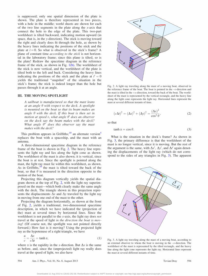
III. THE MOVING SPOTLIGHT
A sailboat is manufactured so that the mast leansat an angle h with respect to the deck. A spotlightis mounted on the boat so that its beam makes anangle h with the deck. If this boat is then set inmotion at speed v, what angle h0 does an observeron the dock say the beam makes with the deck?What angle h00 does this observer say the mastmakes with the deck?
This problem appears in Griffiths;10 an alternate version5
replaces the boat with a spaceship, and the mast with anantenna.
A three-dimensional spacetime diagram in the referenceframe of the boat is shown in Fig. 2. The heavy line repre-sents the light ray and lies along the light cone as shown.The worldsheet of the mast is also shown; it is vertical, sincethe boat is at rest. Since the spotlight is pointed along themast, the light ray must lie within this worldsheet, as shown.As in Griffiths,10 the mast is tilted toward the back of theboat, so that h is measured in the direction opposite to themotion of the boat.
Projecting this diagram vertically yields the spatial dia-gram shown at the top of Fig. 2, with the light ray superim-posed on the mast—which both clearly make the same anglewith the deck. The triangle shown in this projection repre-sents the displacements Dx and Dy traveled by the light rayin moving from one end of the mast to the other.
Projecting the diagram horizontally, as shown at the frontof Fig. 2, yields a traditional, two-dimensional spacetimedescription, in which we have indicated the (projection ofthe) mast at several times by horizontal lines. Since theworldsheet is not parallel to the x-axis, the light ray does nottravel at the speed of light in the direction the boat is mov-ing! (Of course not, the spotlight was not pointed directlyforward.) How fast is it moving? Using the projected lightray as the hypotenuse of a right triangle, we have
u
c¼ Dx
cDt¼ tanh a; (1)
where a is the rapidity in the x-direction. But Dx is the sameas before, and, since the (unprojected) light ray really doestravel at the speed of light, we also have
ðcDtÞ2 ¼ ðDxÞ2 þ ðDyÞ2 ¼ ðDxÞ2
cos2 h; (2)
so that
tanh a ¼ cos h: (3)
What is the situation in the dock’s frame? As shown inFig. 3, the primary difference is that the worldsheet of themast is no longer vertical, since it is moving. But the rest ofthe argument is the same, with Dx0; Dy0, and Dt0 again denot-ing the displacements of the light ray (which do not corre-spond to the sides of any triangles in Fig. 3). The apparent
Fig. 2. A light ray traveling along the mast of a moving boat, observed in
the reference frame of the boat. The boat is pointed in the –x-direction and
the mast is tilted in the þx-direction, toward the back of the boat. The world-
sheet of the mast is represented by the vertical rectangle, and the heavy line
along the light cone represents the light ray. Horizontal lines represent the
mast at several different instants of time.
Fig. 3. A light ray traveling along the mast of a moving boat, according to
an external observer to whom the boat is moving in the –x-direction. The
worldsheet of the mast is represented by the tilted rectangle, and the heavy
line along the light cone represents the light ray. Horizontal lines represent
the mast at several different instants of time.
594 Am. J. Phys., Vol. 81, No. 8, August 2013 Tevian Dray 594
Downloaded 11 Aug 2013 to 128.82.252.58. Redistribution subject to AAPT license or copyright; see http://ajp.aapt.org/authors/copyright_permission

speed of the light ray parallel to the boat is given by theEinstein addition law, which takes the form
u0
c¼ Dx0
cDt0¼ tanhðb� aÞ; (4)
where tanh b ¼ v=c, so that
cosh0 ¼ tanhða�bÞ¼ tanha� tanhb1� tanha tanhb
¼ cosh� tanhb1�cosh tanhb
;
(5)
or in more familiar language,
cos h0 ¼ c cos h� v
c� v cos h: (6)
Determining the angle of the mast is much easier. If themast is at an angle h to the horizontal in the rest frame of theboat, as shown in Fig. 4(a), then
tan h ¼ Dy
Dx: (7)
In the dock frame, y is unchanged, but x is length-contracted,so
tan h00 ¼ Dy0
Dx0¼ Dy
Dx=cosh b¼ tan h cosh b: (8)
Did we really need to refer to the upper, spatial projection inFig. 3 to help visualize this argument? Probably not.
But wait a minute. How can the light ray move along themast if the angles are different? Now the spatial projection atthe top of Fig. 3, reproduced in Fig. 4(b), comes in handy, asit shows a “movie” of the light ray propagating along the(moving) mast despite the fact that the angles between thedeck and the light ray and mast are clearly different. Thesame question could be raised in the Newtonian version ofthe problem, in which a ball is thrown along the mast. The
resolution of this apparent paradox is the same in both con-texts: position and velocity transform differently betweenreference frames, and therefore so do “position angles” and“velocity angles.”
IV. THE LORENTZIAN INNER PRODUCT
Perhaps, the most famous thought experiment ever isEinstein’s argument that the constancy of the speed of lightleads to time dilation: A beam of light bouncing vertically ina (horizontally) moving train travels different distances, andtherefore takes different amounts of time in the moving ref-erence frame than in the rest frame. Thus, the “ticks” of aclock measure different time intervals in the two referenceframes.
This scenario is usually drawn as a purely spatial “movie,”but is inherently three-dimensional. Figure 511 shows theworldlines of a light ray (along the lightcone), an observer atrest (vertical), and the light source on the floor of the movingtrain (tilted to the right).
The projection into a horizontal plane t¼ constant, asshown at the top of Fig. 5, is precisely the standard spatial“movie” shown in Fig. 6(a). This triangle shows the distancevDt traveled by the train (base), the distance cDt traveled bythe beam of light according to the observer on the platform(hypotenuse), and the height of the train (side); that is, thedistance cDt0 traveled by the beam of light according to theobserver on the train. Projecting instead into the verticalplane y¼ 0, as shown on the right of Fig. 5, one obtains thespacetime diagram shown in Fig. 6(b).
Remarkably, the edges of the two triangles formed by thehorizontal and vertical projections have the same lengths. Itis apparent from Fig. 5 that they share one edge. The fourremaining legs consist of two pairs, each of which forms aright triangle, whose hypotenuse is the light ray. So long asone measures time and distance in the same units (thus set-ting c¼ 1), each such triangle is isosceles (the legs have the
Fig. 4. The horizontal projections of the spacetime diagrams in Figs. 2 and 3.
In the boat’s frame (a), the mast is at rest, but in the dock’s frame (b) the
boat moves to the left; the mast is shown at four discrete instants of time.
The beam of light moves along the mast in both cases, as shown by the diag-
onal line in (b) (and not shown separately in (a)).
Fig. 5. A bouncing light ray on a moving train. One “tick” of the light ray is
represented by the diagonal line along the light cone. The vertical projection
(top) yields the usual analysis of time dilation in terms of a Euclidean trian-
gle; the corresponding hyperbolic triangle is obtained from the horizontal
projection (right).
595 Am. J. Phys., Vol. 81, No. 8, August 2013 Tevian Dray 595
Downloaded 11 Aug 2013 to 128.82.252.58. Redistribution subject to AAPT license or copyright; see http://ajp.aapt.org/authors/copyright_permission

same length). This argument justifies the labeling used inFig. 6(b) and can in fact be used to derive the hyperbolicPythagorean theorem, which says that
ðcDt0Þ2 ¼ ðcDtÞ2 � ðvDtÞ2; (9)
or equivalently, that
t0 ¼ t
cosh b; (10)
where tanh b ¼ v=c is the speed of the train. Moving clockstherefore run slow, by a factor of precisely cosh b.
Figures 6(a) and 6(b) thus present the same content, but inquite different ways; two of the sides appear to have beeninterchanged. In Fig. 6(a), the vertical distance traveled bythe light ray was cDt0, whereas in Fig. 6(b), the time taken bythe beam to reach the top of the train is cDt0.
V. CONCLUSION
We have considered three scenarios in special relativitythat lend themselves to an analysis using three-dimensionalspacetime diagrams. In the first scenario, the qualitativeaspects of the diagram immediately yielded insight into thecounterintuitive effects of transforming velocities betweenreference frames, and projections of the three-dimensionaldiagram were used to recover more familiar, two-dimensional diagrams of the same scenario. In the secondscenario, the two-dimensional diagrams played a more fun-damental role, and the three-dimensional spacetime diagramwas used primarily to ensure that the two-dimensional dia-grams were consistent. Finally, in the third scenario, well-known two-dimensional diagrams were combined into a sin-gle three-dimensional diagram, providing new insight into astandard thought experiment about the Lorentzian innerproduct of special relativity. Each of these somewhat differ-ent uses of three-dimensional spacetime diagrams demon-strates the usefulness of such diagrams.
So when are three-dimensional spacetime diagrams use-ful? Diepstraten et al.12 list some of the features of such dia-grams, including the presence of motion in more than onespatial direction, as in the rising manhole example, and theability to present spatial angles, as in the moving spotlightexample. We would add to this list the ability to interpolatebetween traditional spatial “movies,” and (two-dimensional)spacetime diagrams, as in our last example. However, ourgoal here has not been to present general criteria for deter-mining when to (or not to) use such diagrams, but rather todemonstrate by example that they are appropriate in somesituations. A more systematic treatment would also addressthe differences between seeing (using light) and observing(using an army of observers), thus describing what thingslook like, not merely what they do.
ACKNOWLEDGMENTS
The geometric approach to special relativity describedhere and in our previous work5,6,13 grew out of class notesfor a course on Reference Frames,14 which in turn forms partof a major upper-division curriculum reform effort, theParadigms in Physics project,15,16 begun in the Departmentof Physics at Oregon State University in 1997, and supportedin part by NSF Grant Nos. DUE–965320, 0231194,0618877, and 1023120.
a)Electronic mail:[email protected] Foundation, The Mechanical Universe…and Beyond (video
series), Lesson 42: “The Lorentz Transformation” (1985). Viewable in
North America at <http://www.learner.org/resources/series42.html>.2Daniel Weiskopf, “A Survey of Visualization Methods for Special
Relativity,” in Scientific Visualization: Advanced Concepts, edited by H.
Hagen (Dagstuhl Publishing, Saarbr€ucken, Germany, 2010), pp. 289–302,
<http://drops.dagstuhl.de/opus/volltexte/2010/2711/pdf/20.pdf>.3Edwin F. Taylor and John Archibald Wheeler, Spacetime Physics (W. H.
Freeman, San Francisco, 1963).4Edwin F. Taylor and John Archibald Wheeler, Spacetime Physics, 2nd ed.
(W. H. Freeman, New York, 1992).5Tevian Dray, The Geometry of Special Relativity (A K Peters/CRC Press,
Boca Raton, FL, 2012).6Tevian Dray, The Geometry of Special Relativity, <http://physics.oregon-
state.edu/coursewikis/GSR> (2012).7R. Shaw, “Length contraction paradox,” Am. J. Phys. 30, 72 (1962).8W. Rindler, “Length contraction paradox,” Am. J. Phys. 29, 365–366
(1961).9Online versions of these and subsequent figures are available as rotatable
Java applets at <http://physics.oregonstate.edu/coursewikis/GSR/book/
updates/3d>.10David J. Griffiths, Introduction to Electrodynamics, 3rd ed. (Prentice-Hall,
Upper Saddle River, NJ, 1999).11This figure appears opposite the title page of Ref. 7 and is used with permis-
sion; the following discussion is adapted from Sec. 6.4 of that reference.12Joachim Diepstraten, Daniel Weiskopf, and Thomas Ertl, “Automatic
Generation and Non-Photorealistic Rendering of 2þ1D Minkowski
Diagrams,” J. WSCG 10, 139–146 (2002), <http://wscg.zcu.cz/wscg2002/
Papers_2002/F83.pdf>.13Tevian Dray, “The Geometry of Special Relativity,” Phys. Teach. (India)
46, 144–150 (2004).14Tevian Dray, Reference Frames course website, <http://physics.oregonsta-
te.edu/portfolioswiki/courses:home:rfhome>.15Corinne A. Manogue and Kenneth S. Krane, “The Oregon State University
Paradigms Project: Re-envisioning the Upper Level,” Phys. Today 56(9),
53–58 (2003).16Paradigms in Physics Team, Paradigms in Physics project website,
<http://physics.oregonstate.edu/portfolioswiki>.
Fig. 6. The (a) ordinary and (b) spacetime Pythagorean theorem for a bounc-
ing light beam on a moving train.
596 Am. J. Phys., Vol. 81, No. 8, August 2013 Tevian Dray 596
Downloaded 11 Aug 2013 to 128.82.252.58. Redistribution subject to AAPT license or copyright; see http://ajp.aapt.org/authors/copyright_permission