
REKLUSE MOTOR SPORTS · Protect eyes and skin – wear safety glasses and thin disposable work...
35
©2016 Rekluse Motor Sports Rekluse Motor Sports, Inc. 12000 W Franklin Rd. Boise, ID 83709 208-426-0659 [email protected] REKLUSE MOTOR SPORTS INSTALLATION GUIDE Doc ID 191-6301 Revision 123016 OVERVIEW Read the separate included Safety Information document before operating the vehicle with the product installed. If you are performing the installation of this product for a customer or another person, instruct them to read the Safety Information document and the Installation and User Guide before operating the vehicle with the product. Read this entire document before performing any steps, so you will know what to expect. When reinstalling components, use the torque specifications found in your service manual. Torque values listed are valid as of the date shown in the document revision number above. Use clean, quality JASO MA or JASO MA2 certified oil All OEM components will be reused except: This kit will replace all of the OEM frictions and drive plates with a Rekluse thin friction EXP clutch pack. Inspection of OEM components is necessary during installation This kit will replace the OEM pressure plate with a Rekluse pressure plate. This kit will replace the OEM slave cylinder with a Rekluse adjustable slave cylinder. Tuning Note: (especially for 2-Stroke owners): Upon installation of this product, if you desire your clutch to engage more aggressively, a favorable option is to purchase the heavier Belleville spring from KTM (KTM calls it the “280” spring). KTM Part #: 78932005000 This spring will make the clutch engagement more aggressive but will slightly increase the clutch lever pull effort. This spring comes stock on 2013 and newer Factory Edition 450SX-F bikes.
Transcript of REKLUSE MOTOR SPORTS · Protect eyes and skin – wear safety glasses and thin disposable work...
©2016 Rekluse Motor Sports Rekluse Motor Sports, Inc.
12000 W Franklin Rd. Boise, ID 83709 208-426-0659
REKLUSE MOTOR SPORTS
INSTALLATION
GUIDE
Doc ID 191-6301
Revision 123016
OVERVIEW
Read the separate included Safety Information document before operating the vehicle with the product installed.
If you are performing the installation of this product for a customer or another person, instruct them to read the Safety Information document and the Installation and User Guide before operating the vehicle with the product.
Read this entire document before performing any steps, so you will know what to expect.
When reinstalling components, use the torque specifications found in your service manual. Torque values listed are valid as of the date shown in the document revision number above.
Use clean, quality JASO MA or JASO MA2 certified oil
All OEM components will be reused except:
This kit will replace all of the OEM frictions and drive plates with a Rekluse thin friction EXP clutch pack. Inspection of OEM components is necessary during installation
This kit will replace the OEM pressure plate with a Rekluse pressure plate.
This kit will replace the OEM slave cylinder with a Rekluse adjustable slave cylinder.
Tuning Note: (especially for 2-Stroke owners):
Upon installation of this product, if you desire your clutch to engage more aggressively, a
favorable option is to purchase the heavier Belleville spring from KTM (KTM calls it the
“280” spring).
KTM Part #: 78932005000
This spring will make the clutch engagement more aggressive but will slightly increase the
clutch lever pull effort. This spring comes stock on 2013 and newer Factory Edition
450SX-F bikes.
DOC ID 191-6301 REVISION 120216
INSIDE THIS DOCUMENT
INSTALLATION TIPS
TOOLS NEEDED
INCLUDED PARTS
INSTALLATION INSTRUCTIONS
o CLUTCH DISASSEMBLY AND INSTALLATION
o SLAVE CYLINDER DISASSEMBLY AND INSTALLATION
o SETTING THE INSTALLED GAP
o CHECKING FREE PLAY GAIN
o FREE PLAY GAIN TROUBLESHOOTING
o BREAK-IN PROCEDURE
MAINTENANCE
TROUBLESHOOTING GUIDE
o FREE PLAY GAIN TROUBLESHOOTING
o OPTIMIZING EXP ENGAGEMENT
INSTALLATION TIPS
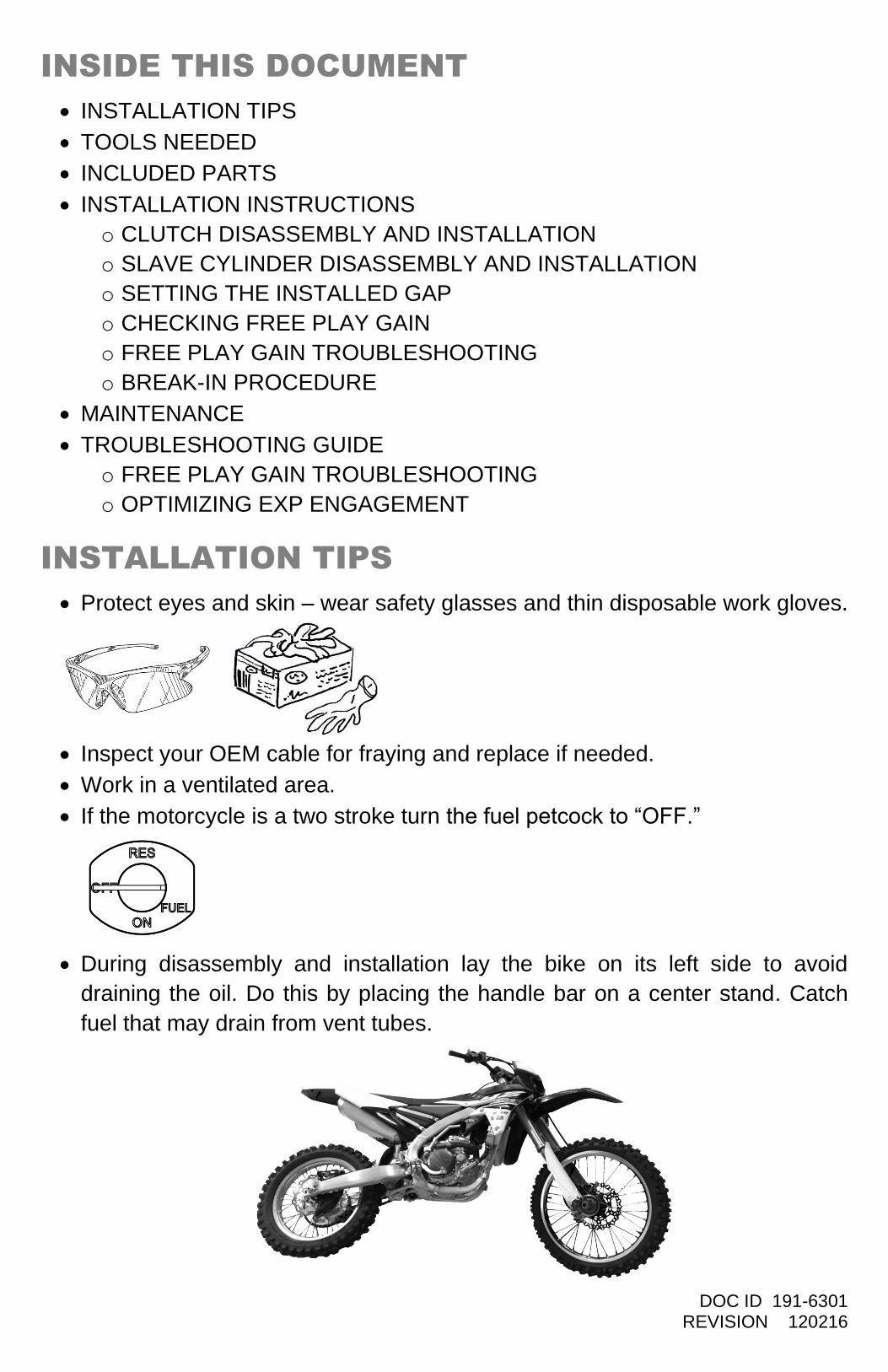
Protect eyes and skin – wear safety glasses and thin disposable work gloves.
Inspect your OEM cable for fraying and replace if needed.
Work in a ventilated area.
If the motorcycle is a two stroke turn the fuel petcock to “OFF.”
During disassembly and installation lay the bike on its left side to avoid
draining the oil. Do this by placing the handle bar on a center stand. Catch
fuel that may drain from vent tubes.

DOC ID 191-6301 REVISION 120216
TOOLS NEEDED
Hydraulic Clutch Fluid
8mm socket 4mm Allen Torque wrench
Metric End Wrench Set
Dental Pick
No Tools Required
Torx Bit T25 Torx Bit T20
T25 T25 T20
DOC ID 191-6301 REVISION 120216
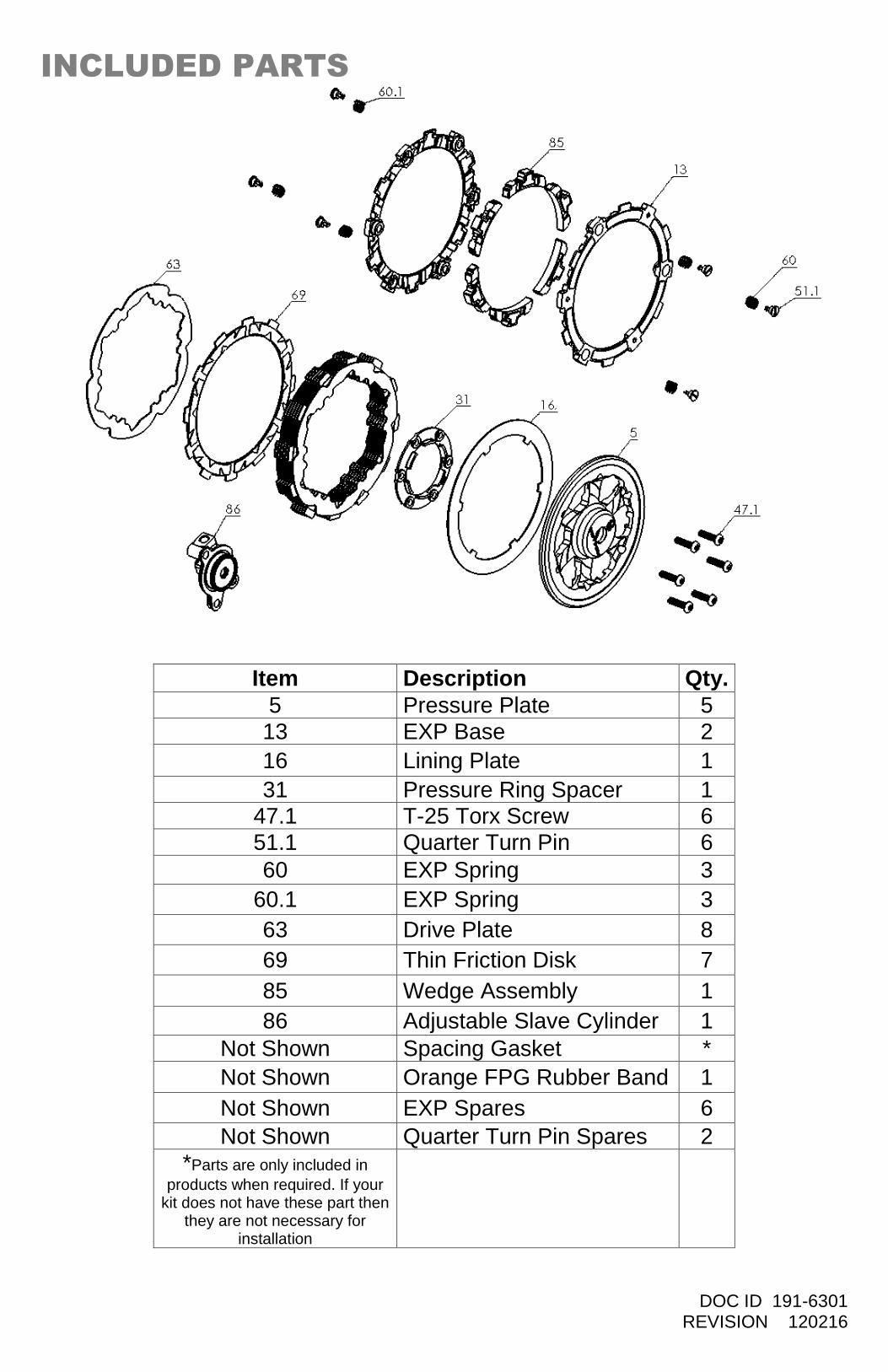
INCLUDED PARTS
Item Description Qty.
5 Pressure Plate 5
13 EXP Base 2
16 Lining Plate 1
31 Pressure Ring Spacer 1 47.1 T-25 Torx Screw 6
51.1 Quarter Turn Pin 6
60 EXP Spring 3
60.1 EXP Spring 3
63 Drive Plate 8
69 Thin Friction Disk 7
85 Wedge Assembly 1
86 Adjustable Slave Cylinder 1
Not Shown Spacing Gasket *
Not Shown Orange FPG Rubber Band 1
Not Shown EXP Spares 6
Not Shown Quarter Turn Pin Spares 2
*Parts are only included in
products when required. If your kit does not have these part then
they are not necessary for installation
DOC ID 191-6301 REVISION 120216
INSTALLATION INSTRUCTIONS
DISASSEMBLY AND INSTALLATION
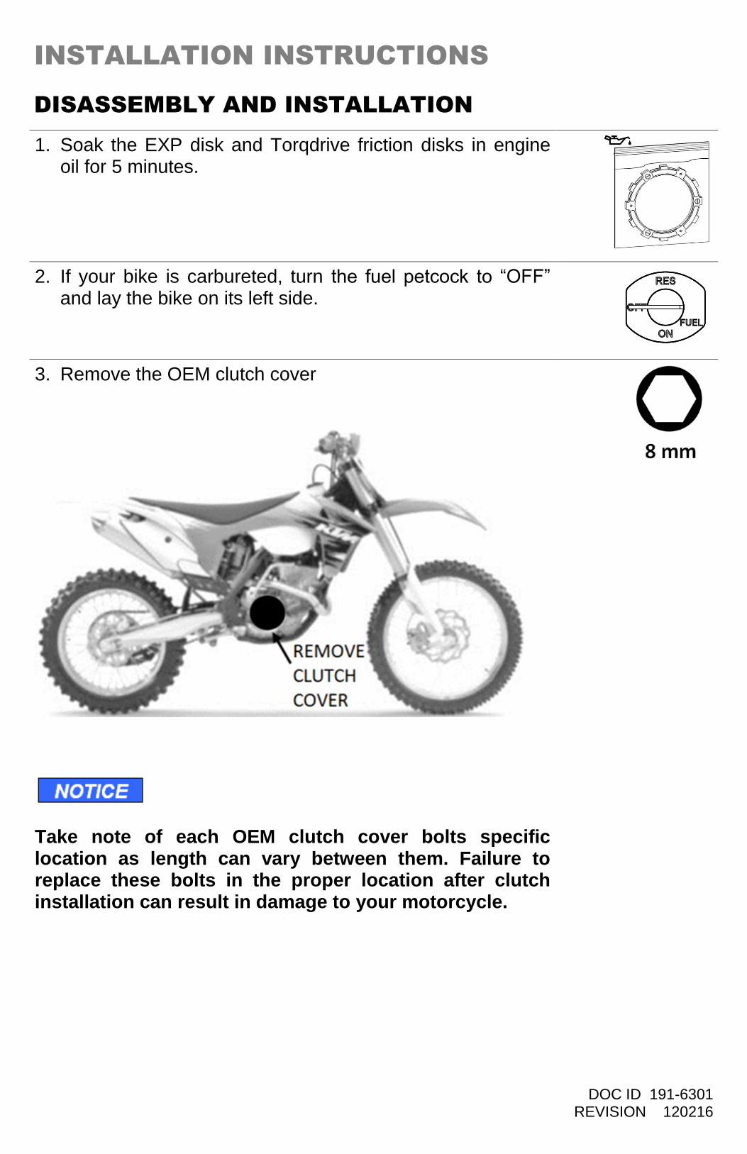
1. Soak the EXP disk and Torqdrive friction disks in engine oil for 5 minutes.
2. If your bike is carbureted, turn the fuel petcock to “OFF” and lay the bike on its left side.
3. Remove the OEM clutch cover
Take note of each OEM clutch cover bolts specific location as length can vary between them. Failure to replace these bolts in the proper location after clutch installation can result in damage to your motorcycle.
DOC ID 191-6301 REVISION 120216
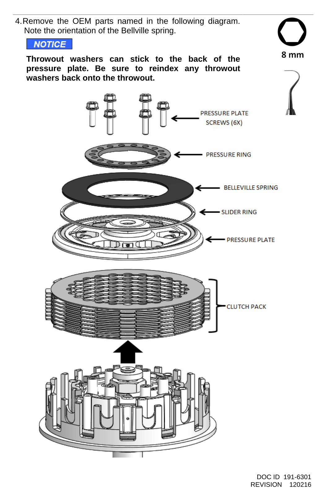
4. Remove the OEM parts named in the following diagram. Note the orientation of the Bellville spring. Throwout washers can stick to the back of the pressure plate. Be sure to reindex any throwout washers back onto the throwout.
DOC ID 191-6301 REVISION 120216
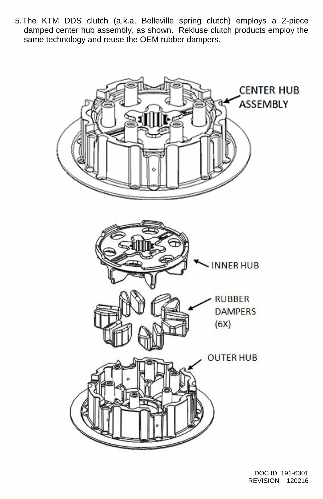
5. The KTM DDS clutch (a.k.a. Belleville spring clutch) employs a 2-piece damped center hub assembly, as shown. Rekluse clutch products employ the same technology and reuse the OEM rubber dampers.
DOC ID 191-6301 REVISION 120216
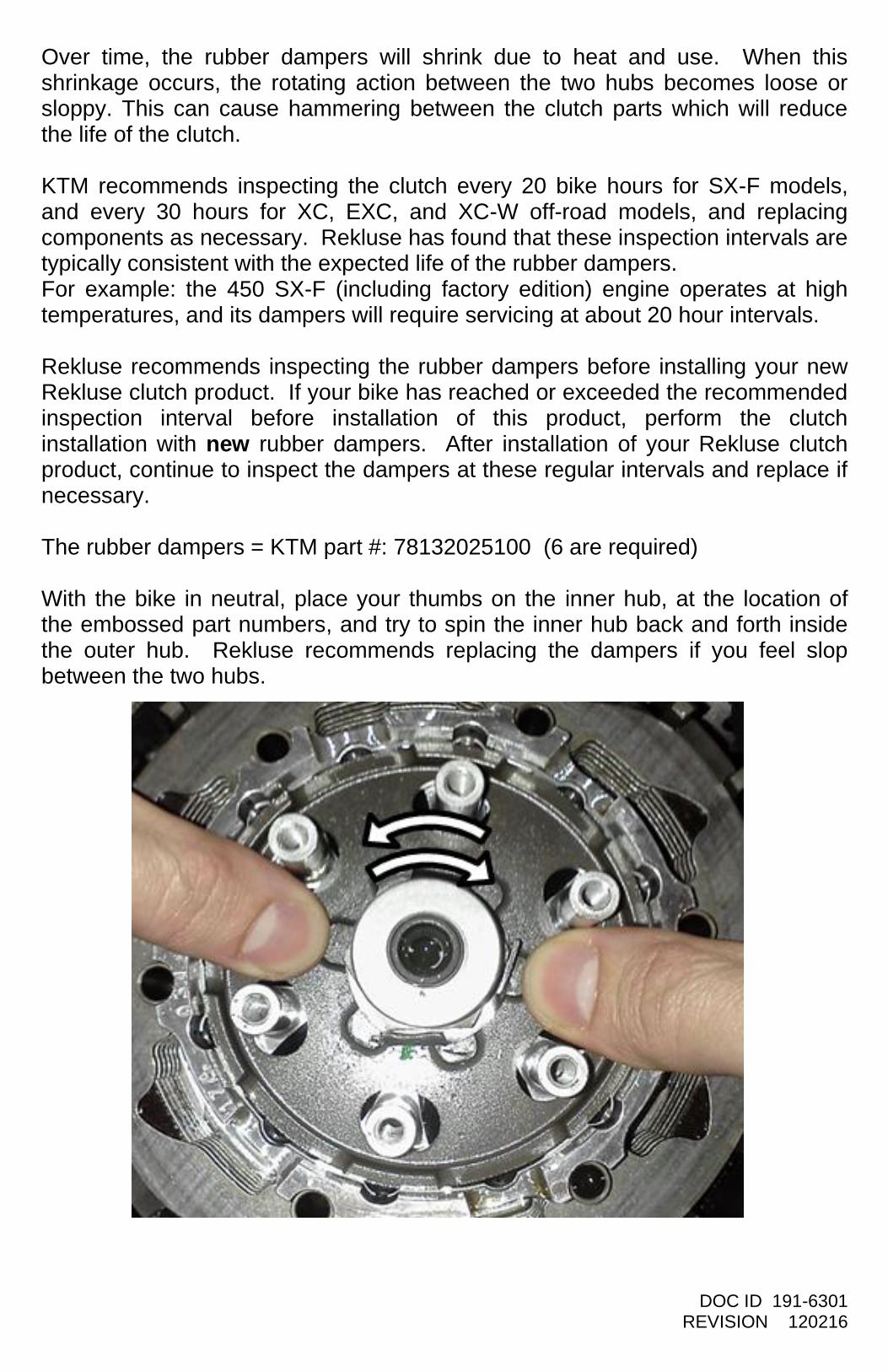
Over time, the rubber dampers will shrink due to heat and use. When this shrinkage occurs, the rotating action between the two hubs becomes loose or sloppy. This can cause hammering between the clutch parts which will reduce the life of the clutch. KTM recommends inspecting the clutch every 20 bike hours for SX-F models, and every 30 hours for XC, EXC, and XC-W off-road models, and replacing components as necessary. Rekluse has found that these inspection intervals are typically consistent with the expected life of the rubber dampers. For example: the 450 SX-F (including factory edition) engine operates at high temperatures, and its dampers will require servicing at about 20 hour intervals. Rekluse recommends inspecting the rubber dampers before installing your new Rekluse clutch product. If your bike has reached or exceeded the recommended inspection interval before installation of this product, perform the clutch installation with new rubber dampers. After installation of your Rekluse clutch product, continue to inspect the dampers at these regular intervals and replace if necessary. The rubber dampers = KTM part #: 78132025100 (6 are required) With the bike in neutral, place your thumbs on the inner hub, at the location of the embossed part numbers, and try to spin the inner hub back and forth inside the outer hub. Rekluse recommends replacing the dampers if you feel slop between the two hubs.
DOC ID 191-6301 REVISION 120216
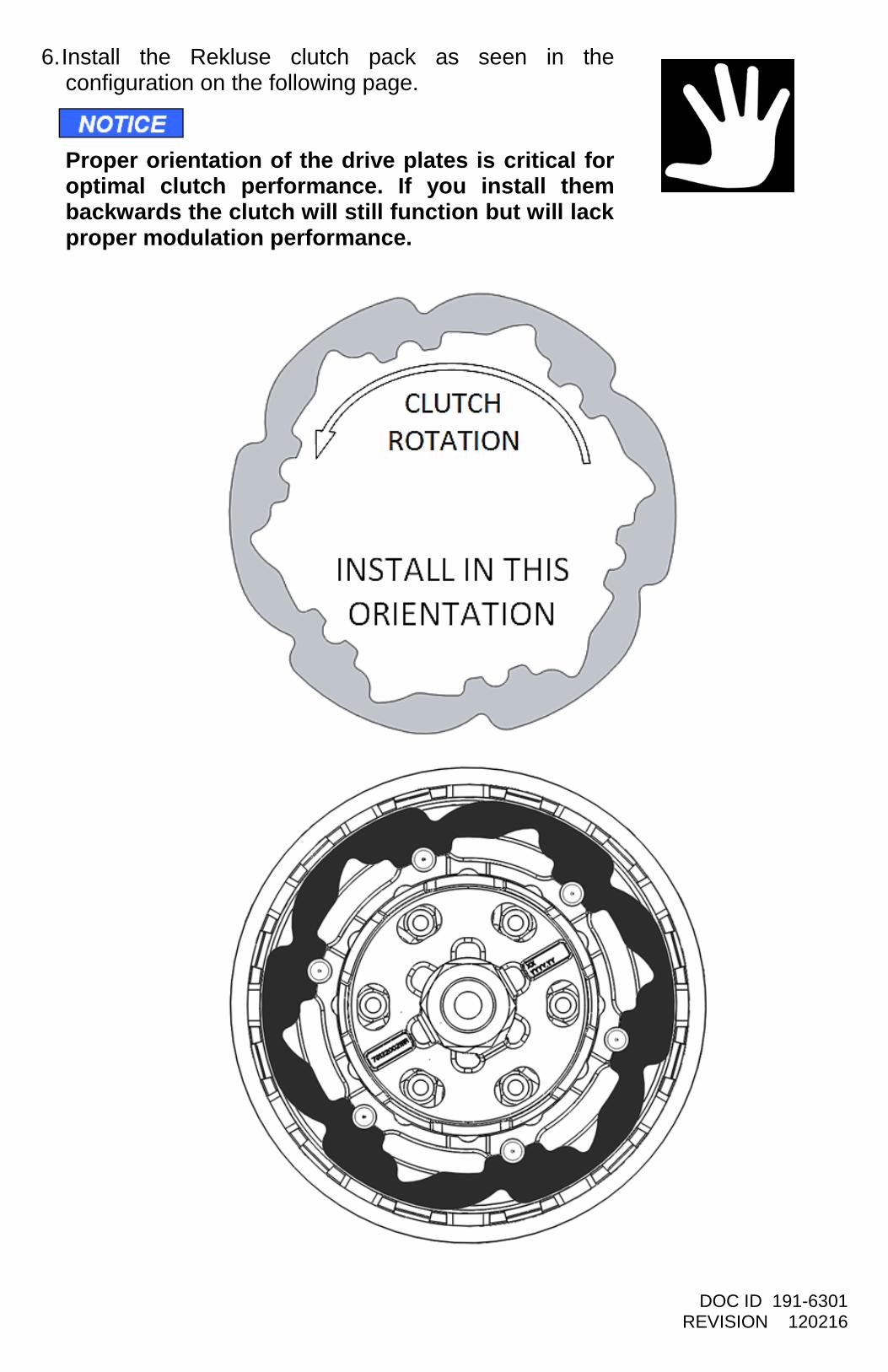
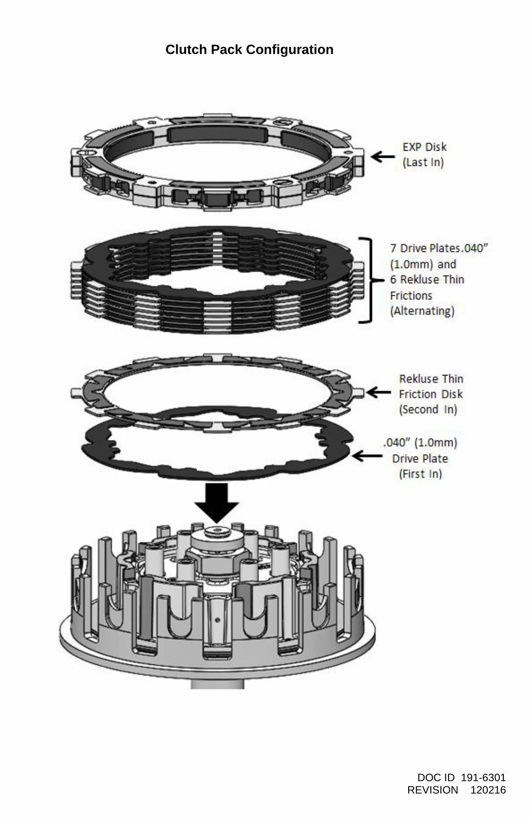
6. Install the Rekluse clutch pack as seen in the configuration on the following page.
Proper orientation of the drive plates is critical for optimal clutch performance. If you install them backwards the clutch will still function but will lack proper modulation performance.
DOC ID 191-6301 REVISION 120216
Clutch Pack Configuration
DOC ID 191-6301 REVISION 120216
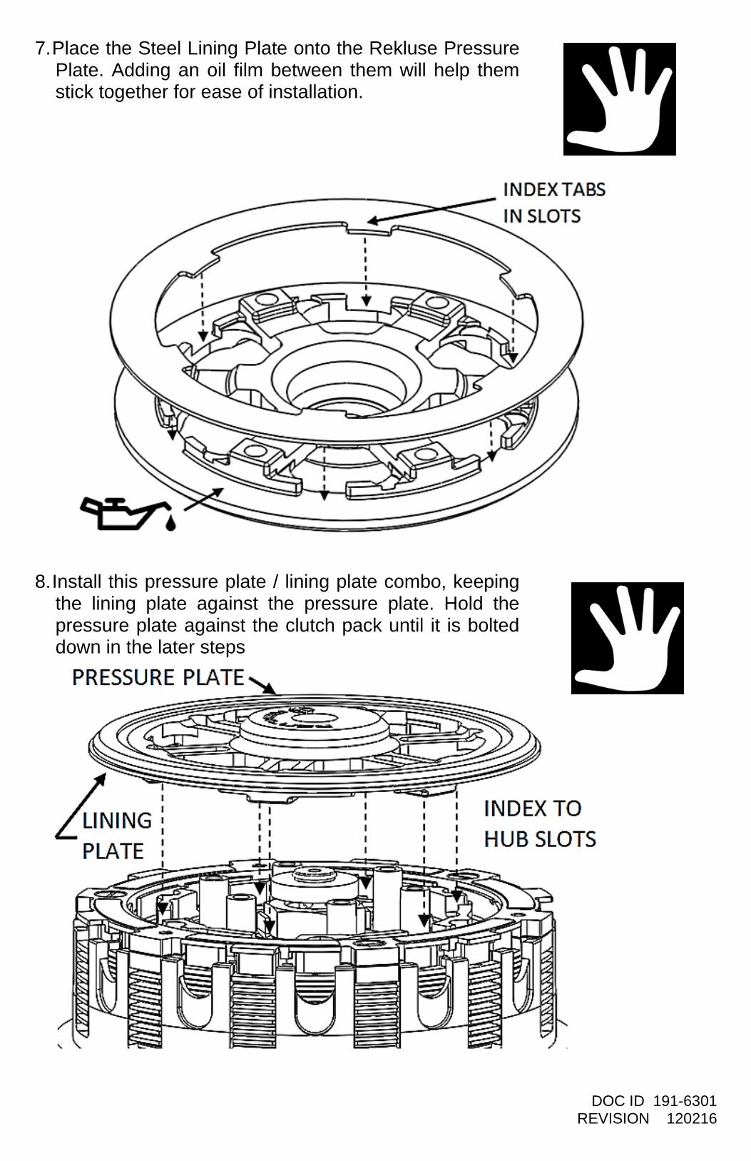
7. Place the Steel Lining Plate onto the Rekluse Pressure Plate. Adding an oil film between them will help them stick together for ease of installation.
8. Install this pressure plate / lining plate combo, keeping the lining plate against the pressure plate. Hold the pressure plate against the clutch pack until it is bolted down in the later steps
DOC ID 191-6301 REVISION 120216
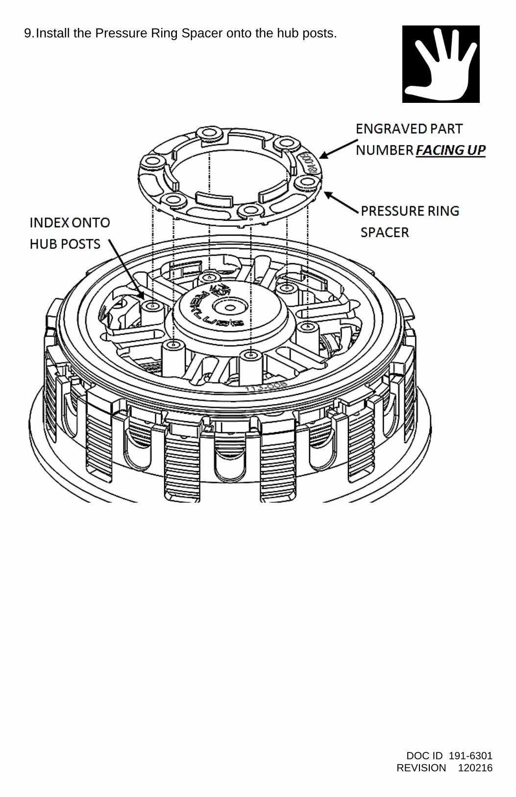
9. Install the Pressure Ring Spacer onto the hub posts.
DOC ID 191-6301 REVISION 120216
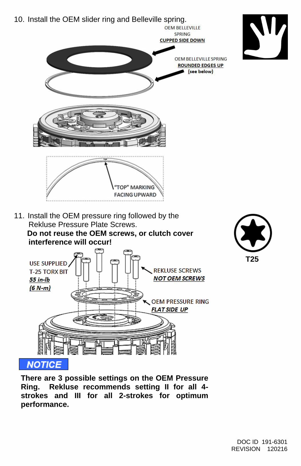
10. Install the OEM slider ring and Belleville spring.
11. Install the OEM pressure ring followed by the Rekluse Pressure Plate Screws. Do not reuse the OEM screws, or clutch cover interference will occur!
There are 3 possible settings on the OEM Pressure Ring. Rekluse recommends setting II for all 4-strokes and III for all 2-strokes for optimum performance.
T25
DOC ID 191-6301 REVISION 120216
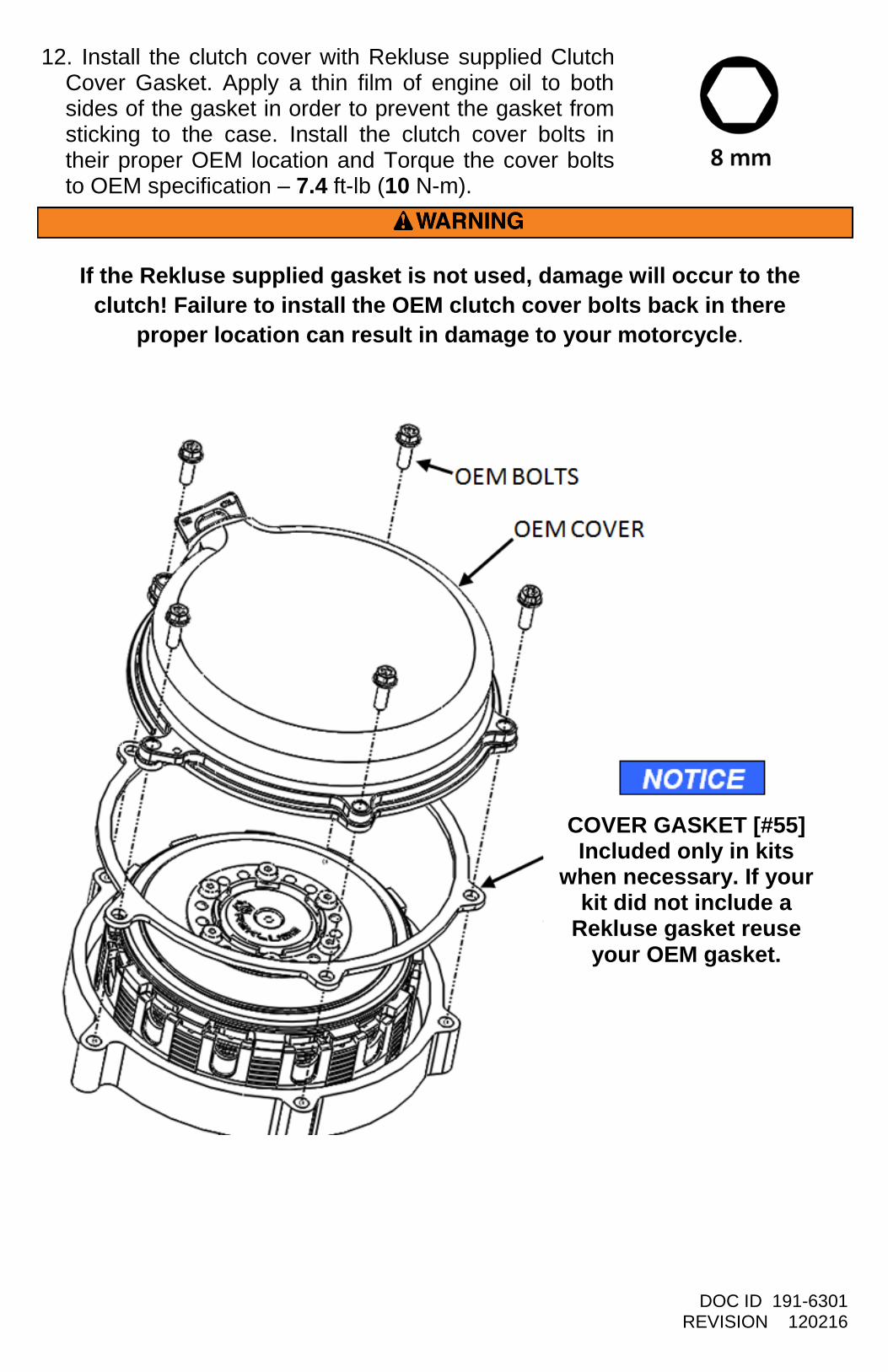
12. Install the clutch cover with Rekluse supplied Clutch Cover Gasket. Apply a thin film of engine oil to both sides of the gasket in order to prevent the gasket from sticking to the case. Install the clutch cover bolts in their proper OEM location and Torque the cover bolts to OEM specification – 7.4 ft-lb (10 N-m).
COVER GASKET [#55] Included only in kits
when necessary. If your kit did not include a
Rekluse gasket reuse your OEM gasket.
If the Rekluse supplied gasket is not used, damage will occur to the
clutch! Failure to install the OEM clutch cover bolts back in there
proper location can result in damage to your motorcycle.
DOC ID 191-6301 REVISION 120216
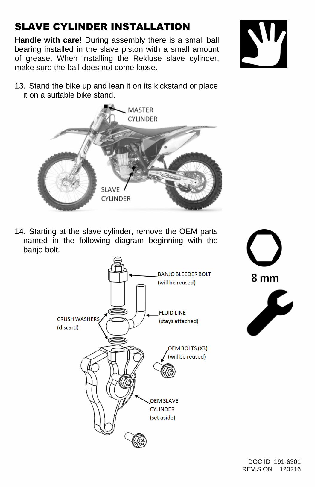
SLAVE CYLINDER INSTALLATION
Handle with care! During assembly there is a small ball bearing installed in the slave piston with a small amount of grease. When installing the Rekluse slave cylinder, make sure the ball does not come loose. 13. Stand the bike up and lean it on its kickstand or place
it on a suitable bike stand.
14. Starting at the slave cylinder, remove the OEM parts named in the following diagram beginning with the banjo bolt.
DOC ID 191-6301 REVISION 120216
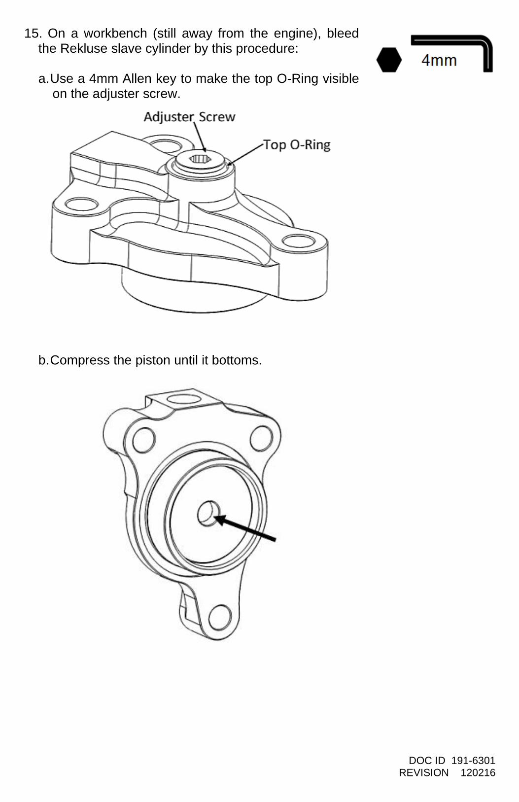
15. On a workbench (still away from the engine), bleed the Rekluse slave cylinder by this procedure: a. Use a 4mm Allen key to make the top O-Ring visible
on the adjuster screw.
b. Compress the piston until it bottoms.
DOC ID 191-6301 REVISION 120216
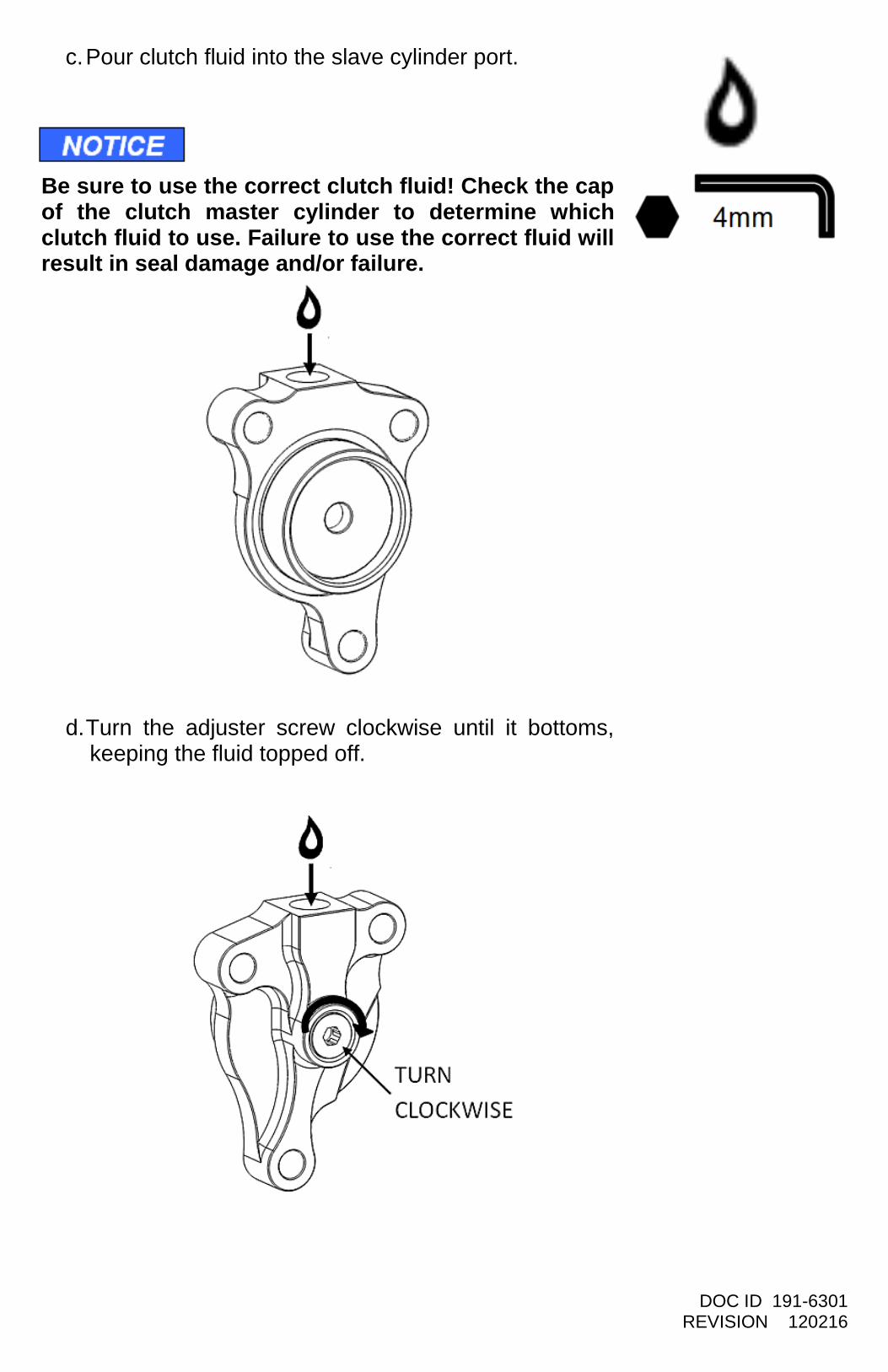
c. Pour clutch fluid into the slave cylinder port.
Be sure to use the correct clutch fluid! Check the cap of the clutch master cylinder to determine which clutch fluid to use. Failure to use the correct fluid will result in seal damage and/or failure.
d. Turn the adjuster screw clockwise until it bottoms, keeping the fluid topped off.
DOC ID 191-6301 REVISION 120216
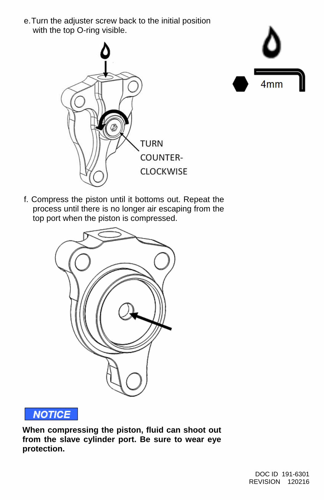
e. Turn the adjuster screw back to the initial position with the top O-ring visible.
f. Compress the piston until it bottoms out. Repeat the
process until there is no longer air escaping from the top port when the piston is compressed.
When compressing the piston, fluid can shoot out from the slave cylinder port. Be sure to wear eye protection.
DOC ID 191-6301 REVISION 120216
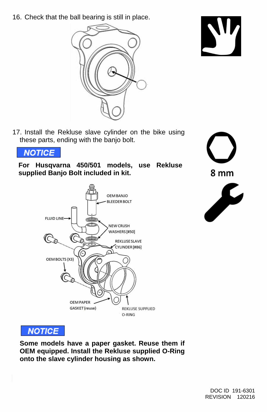
16. Check that the ball bearing is still in place.
17. Install the Rekluse slave cylinder on the bike using these parts, ending with the banjo bolt.
For Husqvarna 450/501 models, use Rekluse supplied Banjo Bolt included in kit. Some models have a paper gasket. Reuse them if OEM equipped. Install the Rekluse supplied O-Ring onto the slave cylinder housing as shown.
DOC ID 191-6301 REVISION 120216
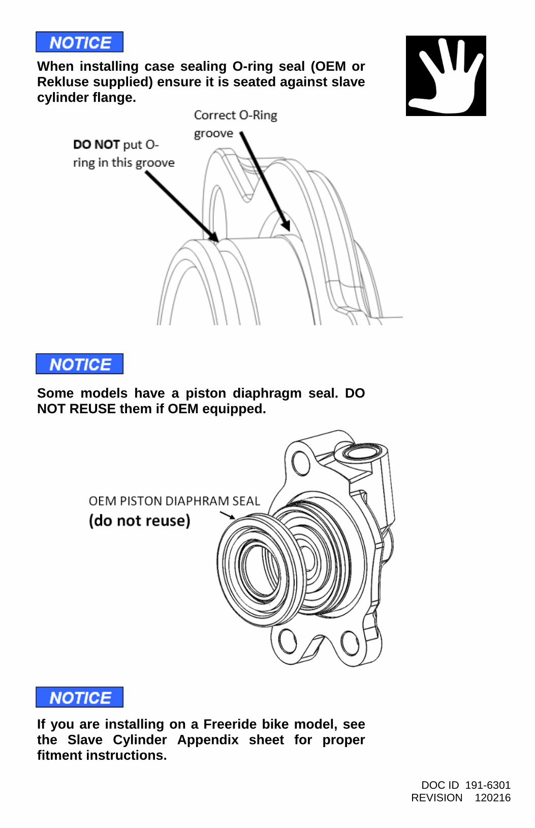
When installing case sealing O-ring seal (OEM or Rekluse supplied) ensure it is seated against slave cylinder flange.
Some models have a piston diaphragm seal. DO NOT REUSE them if OEM equipped.
If you are installing on a Freeride bike model, see the Slave Cylinder Appendix sheet for proper fitment instructions.
DOC ID 191-6301 REVISION 120216
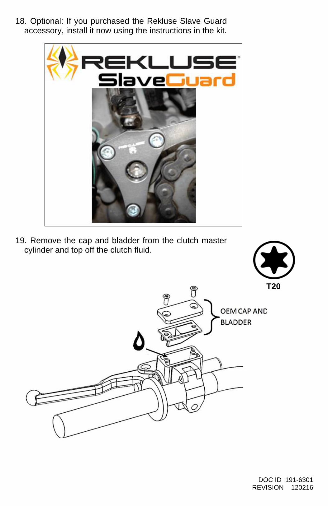
18. Optional: If you purchased the Rekluse Slave Guard accessory, install it now using the instructions in the kit.
19. Remove the cap and bladder from the clutch master cylinder and top off the clutch fluid.
T25 T20
DOC ID 191-6301 REVISION 120216
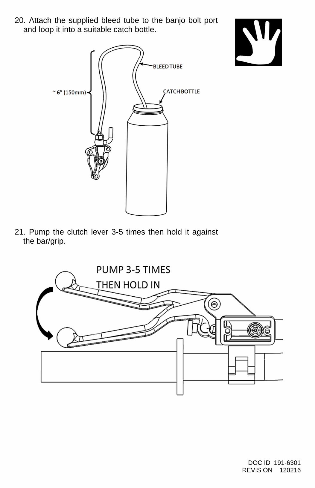
20. Attach the supplied bleed tube to the banjo bolt port and loop it into a suitable catch bottle.
21. Pump the clutch lever 3-5 times then hold it against the bar/grip.
DOC ID 191-6301 REVISION 120216
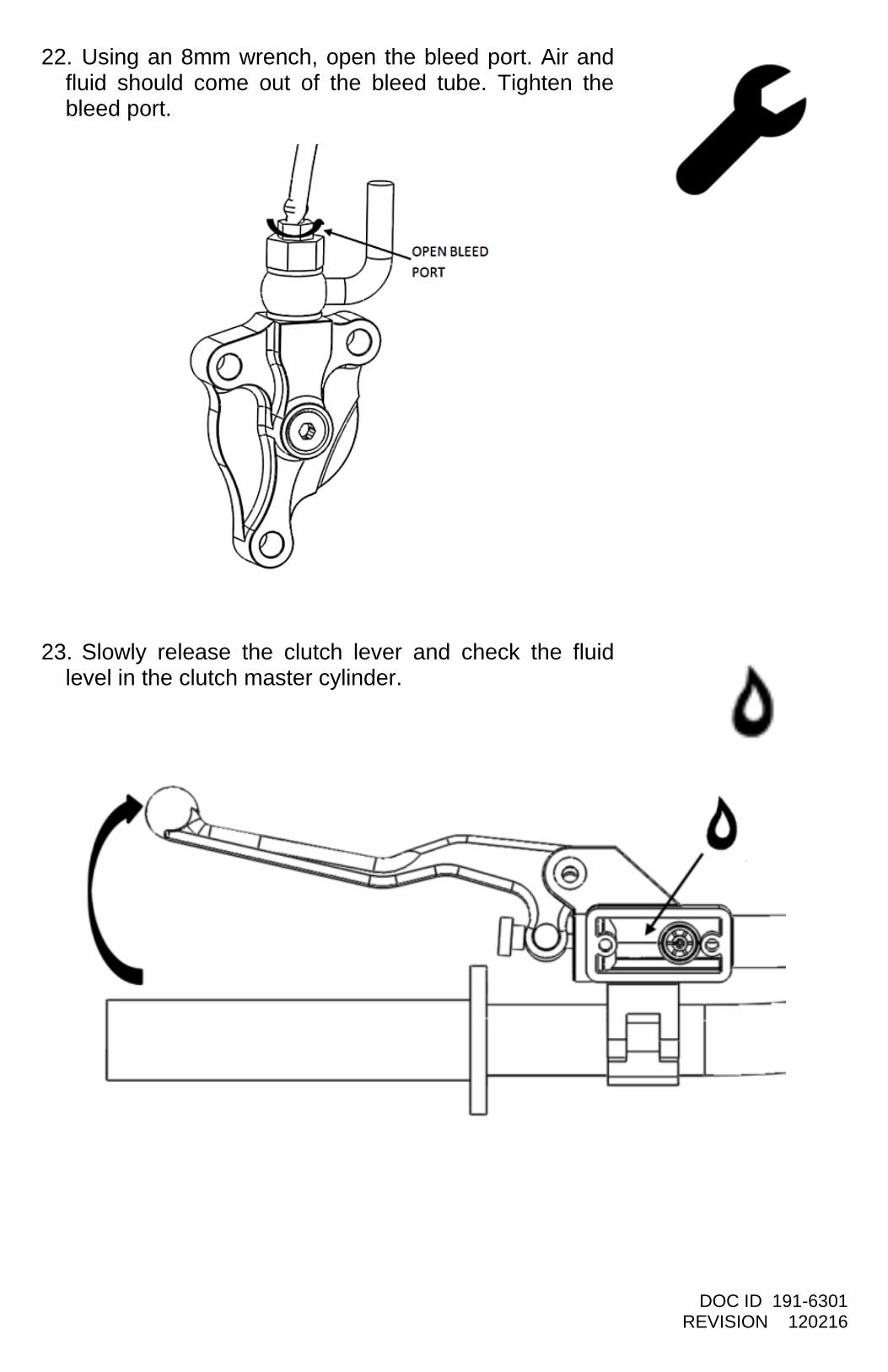
22. Using an 8mm wrench, open the bleed port. Air and fluid should come out of the bleed tube. Tighten the bleed port.
23. Slowly release the clutch lever and check the fluid level in the clutch master cylinder.

DOC ID 191-6301 REVISION 120216
24. Repeat the previous 3 bleeding steps until air no longer comes out of the bleed port. Then, check that the clutch lever functions properly. Repeat the bleeding procedure if necessary.
25. Finally, remove the bleed tube and tighten the bleed port.
DOC ID 191-6301 REVISION 120216
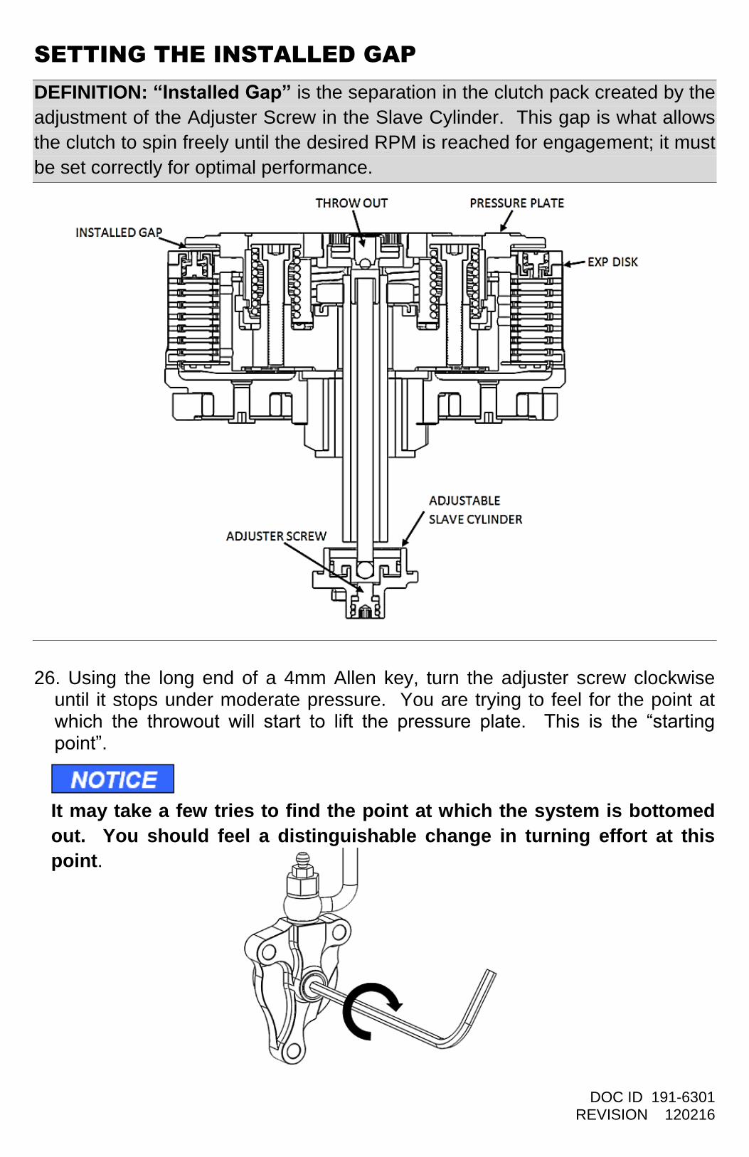
SETTING THE INSTALLED GAP
DEFINITION: “Installed Gap” is the separation in the clutch pack created by the
adjustment of the Adjuster Screw in the Slave Cylinder. This gap is what allows
the clutch to spin freely until the desired RPM is reached for engagement; it must
be set correctly for optimal performance.
26. Using the long end of a 4mm Allen key, turn the adjuster screw clockwise until it stops under moderate pressure. You are trying to feel for the point at which the throwout will start to lift the pressure plate. This is the “starting point”.
It may take a few tries to find the point at which the system is bottomed
out. You should feel a distinguishable change in turning effort at this
point.
DOC ID 191-6301 REVISION 120216
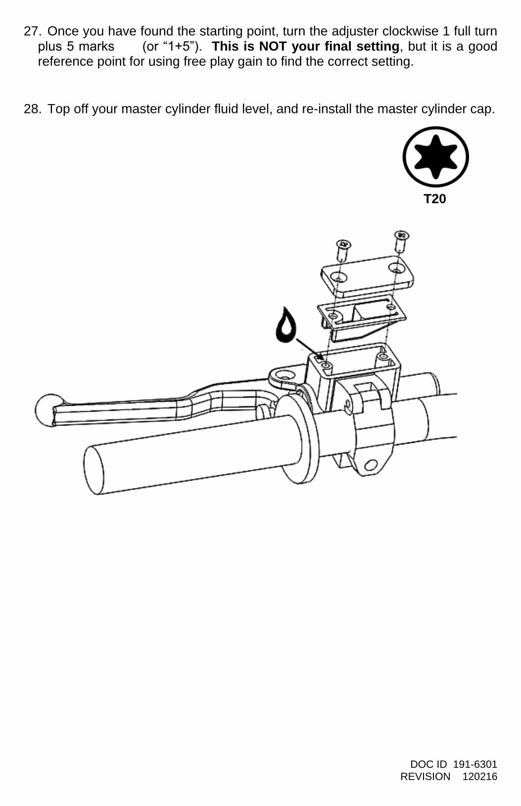
27. Once you have found the starting point, turn the adjuster clockwise 1 full turn plus 5 marks (or “1+5”). This is NOT your final setting, but it is a good reference point for using free play gain to find the correct setting.
28. Top off your master cylinder fluid level, and re-install the master cylinder cap.
T25 T20
DOC ID 191-6301 REVISION 120216
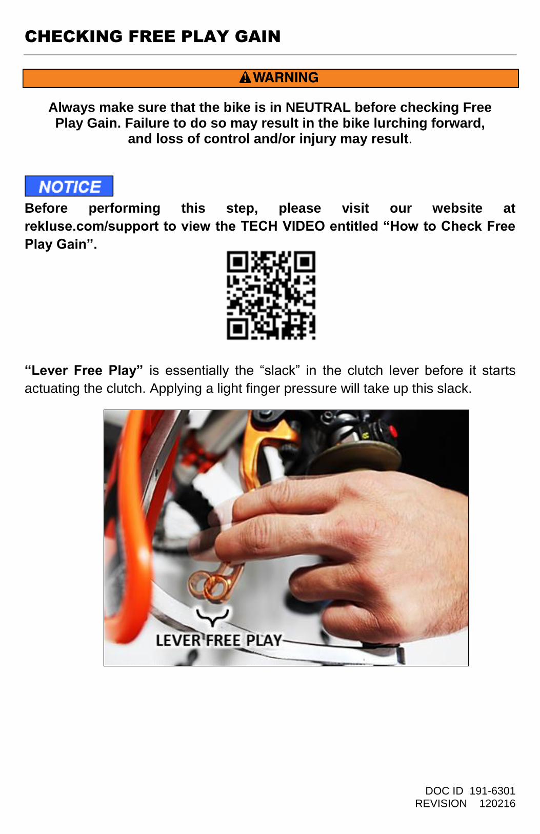
CHECKING FREE PLAY GAIN
Before performing this step, please visit our website at
rekluse.com/support to view the TECH VIDEO entitled “How to Check Free
Play Gain”.
“Lever Free Play” is essentially the “slack” in the clutch lever before it starts
actuating the clutch. Applying a light finger pressure will take up this slack.
Always make sure that the bike is in NEUTRAL before checking Free Play Gain. Failure to do so may result in the bike lurching forward,
and loss of control and/or injury may result.

DOC ID 191-6301 REVISION 120216
“Free Play Gain” is the increase of lever free play as the auto-clutch engages.
This happens when the RPM increase from idle through around 5000 RPM. Free
Play Gain is caused by the expansion of the EXP disk which lifts the pressure
plate away from the throwout assembly.
Optimal Free Play Gain yields 1/8-1/4” (3mm-6mm) of clutch lever movement,
measured at the end of the lever. This measurement at the lever correlates to
achieving the ideal installed gap.
DOC ID 191-6301 REVISION 120216
The following steps explain two ways to check Free Play Gain. One will use the
rubber band that has been included in the clutch kit and one explains using your
hand, which you will perform before every ride.
Place the bike in neutral, start the engine and let it warm up for 2-3 minutes.
RUBBER BAND METHOD
29. We recommend that you use this method to find your initial “Free Play Gain”
so you can see what it is. We recommend also checking it by hand as
explained in the next step so you can check free play gain both ways.
Wrap the included rubber band around the outer end of the handlebar grip and attach to the ball end of the clutch lever. See the following three photos for an example.
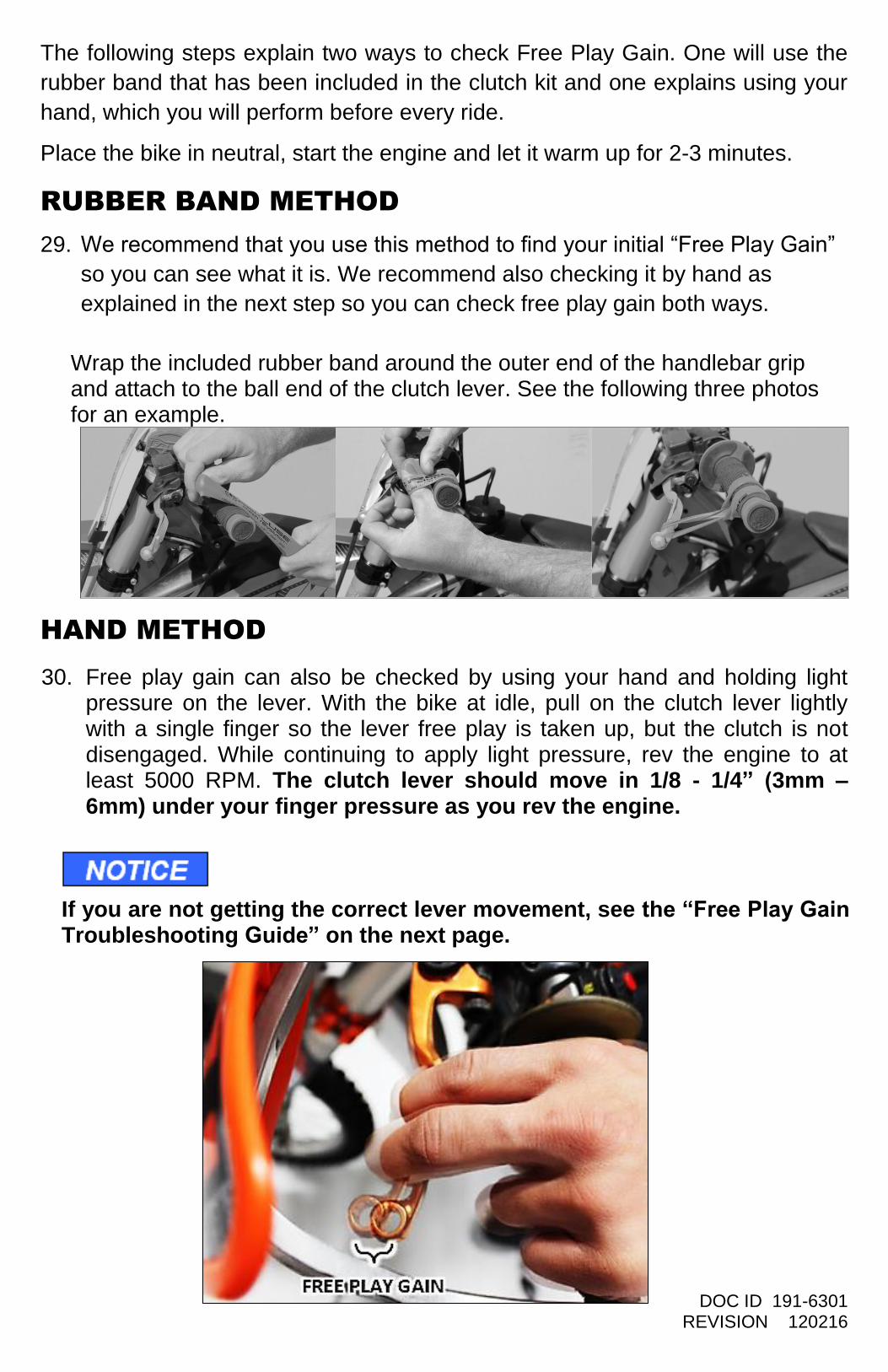
HAND METHOD
30. Free play gain can also be checked by using your hand and holding light pressure on the lever. With the bike at idle, pull on the clutch lever lightly with a single finger so the lever free play is taken up, but the clutch is not disengaged. While continuing to apply light pressure, rev the engine to at least 5000 RPM. The clutch lever should move in 1/8 - 1/4” (3mm – 6mm) under your finger pressure as you rev the engine.
If you are not getting the correct lever movement, see the “Free Play Gain Troubleshooting Guide” on the next page.
DOC ID 191-6301 REVISION 120216
Free Play Gain Troubleshooting
Each adjustment should be done in small increments - one tick mark at a time.
After each adjustment, repeat the rev-cycle until optimal free play gain is
achieved.
Symptom:
- Clutch lever moves in too far (too much free play gain)
- Clutch has excessive drag
- It is difficult to fully override the clutch with the lever
Answer: Installed Gap is too small
Solution: Turn the Adjuster Screw inwardly (clockwise) to increase the Installed
Gap.
Symptom:
- Clutch lever does not move enough or does not move at all (too little free play gain)
- Clutch is slipping
Answer: Installed Gap is too large
Solution: Turn the Adjuster Screw outwardly (counter-clockwise) to reduce the
Installed Gap. It may be helpful to re-find the starting point.
DOC ID 191-6301 REVISION 120216
BREAK-IN PROCEDURE
After desired free play gain is achieved, it is time to break in the EXP disk.
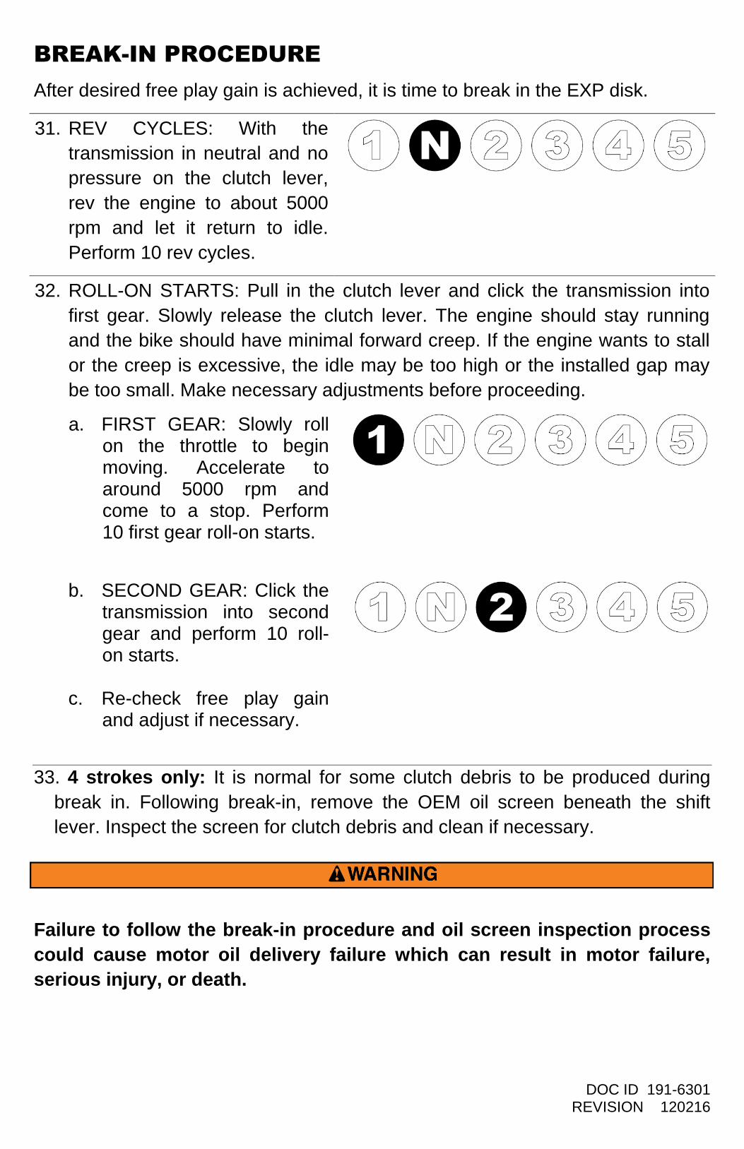
31. REV CYCLES: With the
transmission in neutral and no
pressure on the clutch lever,
rev the engine to about 5000
rpm and let it return to idle.
Perform 10 rev cycles.
32. ROLL-ON STARTS: Pull in the clutch lever and click the transmission into
first gear. Slowly release the clutch lever. The engine should stay running
and the bike should have minimal forward creep. If the engine wants to stall
or the creep is excessive, the idle may be too high or the installed gap may
be too small. Make necessary adjustments before proceeding.
a. FIRST GEAR: Slowly roll on the throttle to begin moving. Accelerate to around 5000 rpm and come to a stop. Perform 10 first gear roll-on starts.
b. SECOND GEAR: Click the transmission into second gear and perform 10 roll-on starts.
c. Re-check free play gain and adjust if necessary.
33. 4 strokes only: It is normal for some clutch debris to be produced during
break in. Following break-in, remove the OEM oil screen beneath the shift
lever. Inspect the screen for clutch debris and clean if necessary.
Failure to follow the break-in procedure and oil screen inspection process
could cause motor oil delivery failure which can result in motor failure,
serious injury, or death.
DOC ID 191-6301 REVISION 120216
Check Free Play Gain before every ride.
Do not perform 3rd
gear starts with this product. 3rd
gear starts over time
will burn up the clutch and decrease the performance of this product in a
short amount of time.
DO NOT RIDE WITHOUT SUFFICIENT FREE PLAY GAIN! Checking free play gain is easy and takes less than a minute to perform. For optimum performance and longevity, check freeplay gain when the bike is warm at the start of every ride.
DOC ID 191-6301 REVISION 120216
MAINTENANCE
Maintenance Protocol (see setup sheet) Maintenance Interval
Check and verify free play gain Every ride
Inspect all clutch parts for excessive wear or heat. Replace as needed.
40 hours
OPTIMIZING EXP ENGAGEMENT
For best performance, engine idle speed should be slightly adjusted to match
the EXP engagement setting.
NOTE: Make sure Free Play Gain is optimal before adjusting idle speed.
With correct Free Play Gain and the bike in gear, the bike should move forward
under slight opening of the throttle. If not, one of the following symptoms is likely:
HIGH IDLE – the bike moves forward with the throttle fully closed. Solution:
reduce idle RPM.
LOW IDLE – the bike moves forward after engine RPM becomes noticeably
higher than idle RPM. Solution: increase idle RPM.
If a slight idle adjustment does not alleviate the problem refer to the EXP
tuning options below for an additional tuning.
DOC ID 191-6301 REVISION 120216
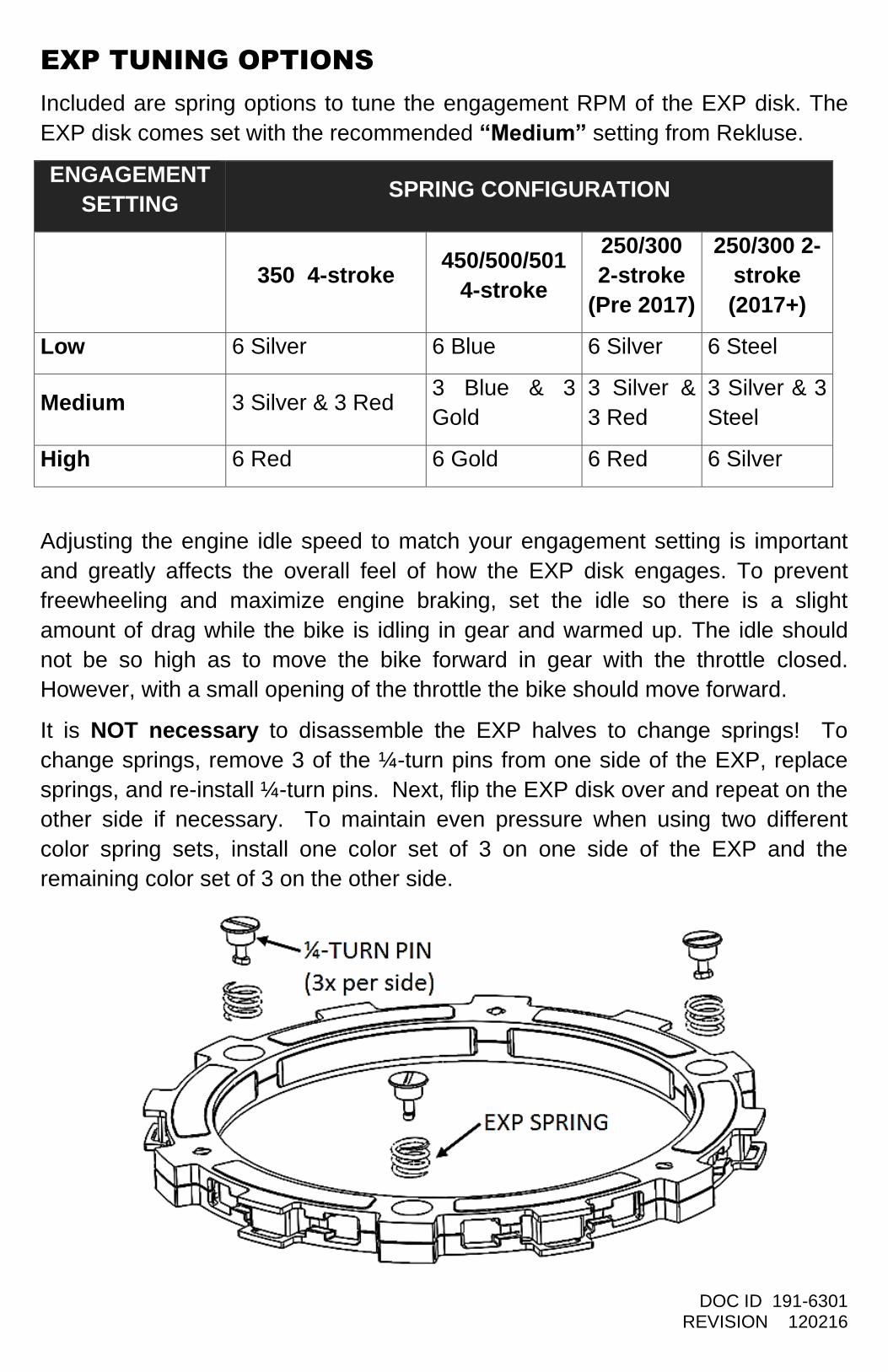
EXP TUNING OPTIONS
Included are spring options to tune the engagement RPM of the EXP disk. The
EXP disk comes set with the recommended “Medium” setting from Rekluse.
ENGAGEMENT
SETTING SPRING CONFIGURATION
350 4-stroke 450/500/501
4-stroke
250/300
2-stroke
(Pre 2017)
250/300 2-
stroke
(2017+)
Low 6 Silver 6 Blue 6 Silver 6 Steel
Medium 3 Silver & 3 Red 3 Blue & 3
Gold
3 Silver &
3 Red
3 Silver & 3
Steel
High 6 Red 6 Gold 6 Red 6 Silver
Adjusting the engine idle speed to match your engagement setting is important
and greatly affects the overall feel of how the EXP disk engages. To prevent
freewheeling and maximize engine braking, set the idle so there is a slight
amount of drag while the bike is idling in gear and warmed up. The idle should
not be so high as to move the bike forward in gear with the throttle closed.
However, with a small opening of the throttle the bike should move forward.
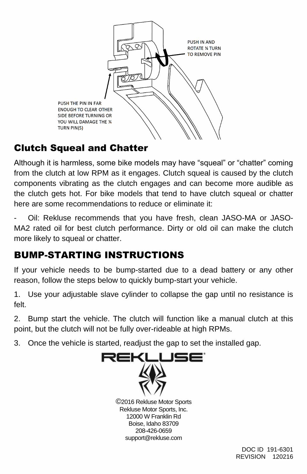
It is NOT necessary to disassemble the EXP halves to change springs! To
change springs, remove 3 of the ¼-turn pins from one side of the EXP, replace
springs, and re-install ¼-turn pins. Next, flip the EXP disk over and repeat on the
other side if necessary. To maintain even pressure when using two different
color spring sets, install one color set of 3 on one side of the EXP and the
remaining color set of 3 on the other side.
DOC ID 191-6301 REVISION 120216
Clutch Squeal and Chatter
Although it is harmless, some bike models may have “squeal” or “chatter” coming
from the clutch at low RPM as it engages. Clutch squeal is caused by the clutch
components vibrating as the clutch engages and can become more audible as
the clutch gets hot. For bike models that tend to have clutch squeal or chatter
here are some recommendations to reduce or eliminate it:
- Oil: Rekluse recommends that you have fresh, clean JASO-MA or JASO-
MA2 rated oil for best clutch performance. Dirty or old oil can make the clutch
more likely to squeal or chatter.
BUMP-STARTING INSTRUCTIONS
If your vehicle needs to be bump-started due to a dead battery or any other
reason, follow the steps below to quickly bump-start your vehicle.
1. Use your adjustable slave cylinder to collapse the gap until no resistance is
felt.
2. Bump start the vehicle. The clutch will function like a manual clutch at this
point, but the clutch will not be fully over-rideable at high RPMs.
3. Once the vehicle is started, readjust the gap to set the installed gap.
©2016 Rekluse Motor Sports
Rekluse Motor Sports, Inc. 12000 W Franklin Rd Boise, Idaho 83709
208-426-0659 [email protected]