
Rekayasa Perangkat Lunak (Software Engineering) M.Sukrisno Mardiyanto Kuliah Umum Universitas Dian...
44
Rekayasa Perangkat Lunak (Software Engineering) M.Sukrisno Mardiyanto Kuliah Umum Universitas Dian Nuswantoro Semarang, 16 Oktober 2008
-
Upload
martin-freeman -
Category
Documents
-
view
222 -
download
0
Transcript of Rekayasa Perangkat Lunak (Software Engineering) M.Sukrisno Mardiyanto Kuliah Umum Universitas Dian...

Rekayasa Perangkat Lunak(Software Engineering)
M.Sukrisno Mardiyanto
Kuliah Umum
Universitas Dian NuswantoroSemarang, 16 Oktober 2008

Definisi Perangkat Lunak
Computer programs and associated documentation (plus configuration data and user training)
Software products may be developed for a particular customer or developed for a general market Generic (shrink-wrapped) - developed to be
sold to a range of different customers Bespoke (custom) - developed for a single
customer according to their specification

Definisi Rekayasa Perangkat Lunak
An engineering discipline which is concerned with all aspects of software production
Engineering discipline Discover solutions by applying theories,
methods or other mechanisms. Work within constraints
All aspects of software production Software development (technical processes) Project management Development of supporting tools, methods
and theories

Misconception

Model Pembangunan P.Lunak A simplified representation of a software
process, presented from a specific perspective
Examples of process perspectives are Workflow perspective - sequence of activities Data-flow perspective - information flow Role/action perspective - who does what
Generic process models Waterfall Iterative development Formal transformation Integration from reusable components

Waterfall ModelRequirements
definition
System andsoftware design
Implementationand unit testing
Integration andsystem testing
Operation andmaintenance

Spiral Model
Riskanalysis
Riskanalysis
Riskanalysis
Riskanalysis Proto-
type 1
Prototype 2Prototype 3
Opera-tionalprotoype
Concept ofOperation
Simulations, models, benchmarks
S/Wrequirements
Requirementvalidation
DesignV&V
Productdesign Detailed
design
CodeUnit test
IntegrationtestAcceptance
testService Develop, verifynext-level product
Evaluate alternativesidentify, resolve risks
Determine objectivesalternatives and
constraints
Plan next phase
Integrationand test plan
Developmentplan
Requirements planLife-cycle plan
REVIEW

Evolutionary Model
ValidationFinal
version
DevelopmentIntermediate
versions
SpecificationInitial
version
Outlinedescription
Concurrentactivities

Incremental Model
Valida teincrement
Develop systemincrement
Design systemarchitecture
Integrateincrement
Valida tesystem
Define outline requirements
Assign requirements to increments
System incomplete
Finalsystem
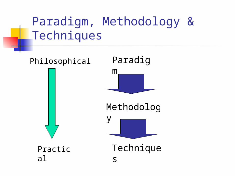
Paradigm, Methodology & Techniques
Paradigm
Methodology
Techniques
Philosophical
Practical

Metodologi Pembangunan P.Lunak
Process model (Data-flow Oriented)
Data model (Data-structure Oriented)
Object model (Object-oriented)

Pemodelan Perangkat Lunak
Data flow model showing how the data is processed at different stages.
Composition model showing how entities are composed of other entities.
Architectural model showing principal sub-systems.
Classification model showing how entities have common characteristics.
Stimulus/response model showing the system’s reaction to events.
Process Model (1)
Process models show the overall process and the processes that are supported by the system
Data flow models may be used to show the processes and the flow of information from one process to another

Process Model (2)
Get costestimates
Acceptdelivery ofequipment
Checkdelivered
items
Validatespecification
Specifyequipmentrequired
Choosesupplier
Placeequipment
order
Installequipment
Findsuppliers
Supplierdatabase
Acceptdelivered
equipment
Equipmentdatabase
Equipmentspec.
Checkedspec.
Deliverynote
Deliverynote
Ordernotification
Installationinstructions
Installationacceptance
Equipmentdetails
Checked andsigned order form
Orderdetails +
Blank orderform
Spec. +supplier +estimate
Supplier listEquipment
spec.
Data Flow Model : Procurement System

Behavioral Model
Behavioural models are used to describe the overall behaviour of a system.
Two types of behavioural model are: Data processing models that show how
data is processed as it moves through the system;
State machine models that show the systems response to events.
Data-processing models
Data flow diagrams (DFD) are used to model the system’s data processing
These show the processing steps as data flows through a system
Intrinsic part of many analysis methods
Simple and intuitive notation that customers can understand easily

Elements of a DFD
Processes Change the data. Each process has one or more
inputs and outputs Data stores
used by processes to store and retrieve data (files, DBs)
Data flows movement of data among processes and data
stores External entities
outside things which are sources or destinations of data to the system

Contoh DFD : Ordering system
Completeorder form
Orderdetails +
blankorder form
Valida teorder
Recordorder
Send tosupplier
Adjustavailablebudget
Budgetfile
Ordersfile
Completedorder form
Signedorder form
Signedorder form
Checked andsigned order
+ ordernotification
Orderamount
+ accountdetails
Signedorder form
Orderdetails

State machine models
These model the behaviour of the system in response to external and internal events.
They show the system’s responses to stimuli so are often used for modelling real-time systems.
Statecharts are an integral part of the UML and are used to represent state machine models.

Statecharts
Allow the decomposition of a model into sub-models (see following slide).
A brief description of the actions is included following the ‘do’ in each state.
Can be complemented by tables describing the states and the stimuli.
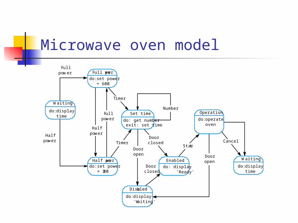
Microwave oven model
Full power
Enabled
do: operateoven
Fullpower
Halfpower
Halfpower
Fullpower
Number
Dooropen
Doorclosed
Doorclosed
Dooropen
Start
do: set power= 600
Half powerdo: set power
= 300
Set time
do: get numberexit: set time
Disabled
Operation
Cancel
Waiting
do: displaytime
Waiting
do: displaytime
do: display 'Ready'
do: display'Waiting'
Timer
Timer
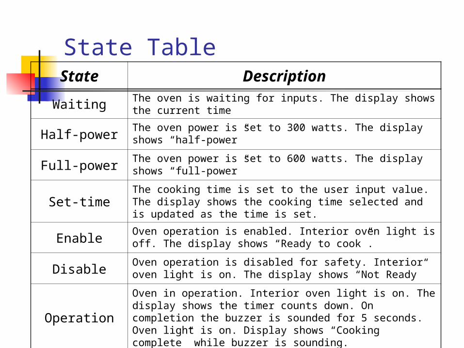
State TableState Description
Waiting The oven is waiting for inputs. The display shows the current time
Half-power The oven power is set to 300 watts. The display shows “half-power”
Full-power The oven power is set to 600 watts. The display shows “full-power”
Set-timeThe cooking time is set to the user input value. The display shows the cooking time selected and is updated as the time is set.
Enable Oven operation is enabled. Interior oven light is off. The display shows “Ready to cook”.
Disable Oven operation is disabled for safety. Interior oven light is on. The display shows “Not Ready”
Operation
Oven in operation. Interior oven light is on. The display shows the timer counts down. On completion the buzzer is sounded for 5 seconds. Oven light is on. Display shows “Cooking complete” while buzzer is sounding.
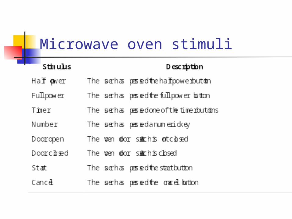
Microwave oven stimuli

Microwave oven operation
Cookdo: run
generator
Done
do: buzzer onfor 5 secs.
Waiting
Alarm
do: displayevent
do: checkstatus
Checking
Turntablefault
Emitterfault
Disabled
OK
Timeout
Time
Door open Cancel
Operation

Semantic data models
Used to describe the logical structure of data processed by the system.
An entity-relation-attribute model sets out the entities in the system, the relationships between these entities and the entity attributes
Widely used in database design. Can readily be implemented using relational databases

Library semantic modelSource
titlepublisherissuedatepages
1
Article
titleauthorspdf filefee
has-links
1
Buyer
nameaddresse-mailbilling info
places
fee-payable-to
n
1
n
published-in
deliversin
m n
1
1
1
CopyrightAgencynameaddress
Country
copyright formtax rate
1
Order
order numbertotal paymentdatetax status
in
1
Data Dictionary
Data dictionaries are lists of all of the names used in the system models. Descriptions of the entities, relationships and attributes are also included.
Advantages Support name management and avoid
duplication; Store of organisational knowledge
linking analysis, design and implementation;
Object models (1)
Object models describe the system in terms of object classes and their associations.
An object class is an abstraction over a set of objects with common attributes and the services (operations) provided by each object.
Various object models may be produced Inheritance models; Aggregation models; Interaction models.

Object models (2)
Natural ways of reflecting the real-world entities manipulated by the system
More abstract entities are more difficult to model using this approach
Object class identification is recognised as a difficult process requiring a deep understanding of the application domain
Object classes reflecting domain entities are reusable across systems

Inheritance model
Organise the domain object classes into a hierarchy.
Classes at the top of the hierarchy reflect the common features of all classes.
Object classes inherit their attributes and services from one or more super-classes. these may then be specialised as necessary.
Class hierarchy design can be a difficult process if duplication in different branches is to be avoided.

Object models and UML
The UML is a standard representation devised by the developers of widely used object-oriented analysis and design methods.
It has become an effective standard for object-oriented modelling.

Example : Library System
Super Class : - Library item - Library user
Class “Library item” : - Published item - Recorded item
Class “Library user” : - Reader - Borrower

Library class hierarchy
Catalogue numberAcquisition dateCostTypeStatusNumber of copies
Library item
Acquire ()Catalogue ()Dispose ()Issue ()Return ()
AuthorEditionPublication dateISBN
Book
YearIssue
Magazine
DirectorDate of releaseDistributor
Film
VersionPlatform
Computerprogram
TitlePublisher
Published item
TitleMedium
Recorded item

User Class hierarchy
NameAddressPhoneRegistration #
Library user
Register ()De-register ()
Affiliation
Reader
Items on loanMax. loans
Borrower
DepartmentDepartment phone
Staff
Major subjectHome address
Student

Multiple inheritance
Rather than inheriting the attributes and services from a single parent class, a system which supports multiple inheritance allows object classes to inherit from several super-classes.
This can lead to semantic conflicts where attributes/services with the same name in different super-classes have different semantics.
Multiple inheritance makes class hierarchy reorganisation more complex.

Multiple inheritance : example
# Tapes
Talking book
AuthorEditionPublication dateISBN
Book
SpeakerDurationRecording date
Voice recording

Object aggregation
An aggregation model shows how classes that are collections are composed of other classes.
Aggregation models are similar to the part-of relationship in semantic data models.

Object aggregation (example)
Videotape
Tape ids.
Lecturenotes
Text
OHP slides
Slides
Assignment
Credits
Solutions
TextDiagrams
Exercises
#ProblemsDescription
Course titleNumberYearInstructor
Study pack

Object behaviour modelling
A behavioural model shows the interactions between objects to produce some particular system behaviour that is specified as a use-case.
Sequence diagrams (or collaboration diagrams) in the UML are used to model interaction between objects.

Issues of Electronic item
:Library User
Ecat:Catalog
Lookup
Issue
Display
:Library ItemLib1:NetServer
Issue licence
Accept licence
Compress
Deliver

Unified Modeling Language (UML)
Use case Diagram Class Diagram Sequence Diagram Collaboration Diagram Interaction Diagram State chart Diagram Component Diagram Deployment Diagram

CASE Tools
IBM Rational Rose Argo UML Poseidon UML

Advance Methodologies & its future
Aspect-oriented Software development eXtreme Programming (XP) Agile Software Development method

Referensi
Ian Sommerville Roger S. Presman Ivar Jacobson


