
Rehabilitation of Structural Columns by Using Steel Angles · Rehabilitation of Structural Columns...
7
International Journal of Scientific & Engineering Research, Volume 6, Issue 1, January-2015 981 ISSN 2229-5518 IJSER © 2015 http://www.ijser.org Rehabilitation of Structural Columns by Using Steel Angles Dr. Ragheed Fatehi Makki, Dr. Salah Talib Nimnim Abstracted- Reinforced concrete (RC) columns in buildings often need rehabilitation either due to defects in the columns themselves, hav- ing to support higher loads than those foreseen in the initial design of the structure, or as the result of ageing or accidental damage. The use of steel caging for this purpose is now a common practice in many countries throughout the world. In this paper, experimental works is present- ed to investigate the behavior of of reinforced concrete columns strengthened externally with steel jacket under axial loads. This experimental work comprises of twelve square reinforced concrete columns with same cross section of (120x120)mm and height of 1000mm. These col- umns divided to four groups, the first group (includes three columns) represents the control samples i.e without any type of strengthening, second group (includes three columns) strengthened by various sizes of four vertical steel angles at column corners linked by horizontal bat- tens, third group (includes three columns) strengthened by constant sizes of four vertical steel angles at column corners linked by various sizes of steel plates at top and bottom of columns, while fourth group (includes three columns) strengthened by constant sizes of four vertical steel angles at column corners linked by (various sizes of steel plates at top and bottom of columns besides horizontal battens).The results show that the rehabilitation technique (strengthening) of R.C. columns by using external steel jacket can increase the ultimate load from (42.2-121.7)%. Index Terms- Rehabilitation, R.C.columns, Steel angles, Steel jacket. —————————— —————————— 1.INTRODUCTION trengthening of reinforced concrete columns using steel angles and steel plates is becoming a widely accepted technology in the construction industry. The composite concrete-steel materials, as exhibiting high stiffness, appeared as innovated solutions adapted for strengthening and repair of the structural columns. The best benefit of using steel angles and steel plates in strengthening of RC columns is not only for increasing the load-carrying capacity but also for the pro- nounced effect on the column stiffness and ductility (Khalifa & Al-Tersawy, 2014). In the last three decades, many im- portant researches performed in this area of strengthening RC columns, first for experimental studies (Ramirez et al., 1997, Adam et al., 2008, Li & Gong, 2009, Campione & Minafo, 2010). Also many theoretical models have been conducted to investigate the behavior of confined and unconfined axially loaded reinforced concrete columns (Critek, 2001, Barga et al., 2006, Campione, 2008, Adam et al., 2009) focused on the be- havior of strengthened reinforced concrete composite columns subjected to failure. However, most of the studies addressed separately the increase in load carrying capacity to the con- finement of concrete core or to the composite action if angels are directly loaded. 2. EXPERIMENTAL WORK The main purpose of the test program is to generate data and provide information about the structural behavior and the ultimate strength of reinforce concrete columns strengthened by steel jacket subjected to axial compressive load through a series of twelve columns, in order to use these type of columns in many applications. The experimental work is carried-out in the Structural Laboratory of the College of Engineering, Uni- versity of Kufa. The parameters considered are : 1- Change of dimensions of angles. 2- Change of dimensions of plates. 3- The effect of using battens. 3- MATERIALS USED TO FABRICATE THE SPECIMENS The materials used in this paper are commercially available materials, which include cement, reinforcing bars, natural gravel and sand. 3.1- CEMENT Ordinary Portland cement manufactured by TASLUJA BAZI- AN CEMENT COMPANY (Product of SULAYMANIYAH- IRAQ) is used throughout the investigation. The cement was kept in closed plastic containers throughout the experimental work to keep the cement in good condition to minimize the effect of humidity. The cement properties conform to the Iraqi Specifications limits (I.O.S. 5/1984) (Iraqi Specification No. 5, 1984) for ordinary Portland cement. 3.2- COARSE AGGREGATE (GRAVEL) Natural gravel obtained from Al-Badra-wa-Jasan is used throughout the experimental work. Its grading satisfied the S ———————————————— • Dr.Ragheed Fatehi Makki (Lecturer), is currently one of staff at faculity of engineering in University of kufa, Iraq. E-mail: [email protected] • Dr.Salah Talib Nimnim (Lecturer), is currently one of staff at faculity of engineering in University of kufa, Iraq. E-mail: [email protected] IJSER
Transcript of Rehabilitation of Structural Columns by Using Steel Angles · Rehabilitation of Structural Columns...
International Journal of Scientific & Engineering Research, Volume 6, Issue 1, January-2015 981 ISSN 2229-5518
IJSER © 2015 http://www.ijser.org
Rehabilitation of Structural Columns by Using Steel Angles
Dr. Ragheed Fatehi Makki, Dr. Salah Talib Nimnim
Abstracted- Reinforced concrete (RC) columns in buildings often need rehabilitation either due to defects in the columns themselves, hav-ing to support higher loads than those foreseen in the initial design of the structure, or as the result of ageing or accidental damage. The use of steel caging for this purpose is now a common practice in many countries throughout the world. In this paper, experimental works is present-ed to investigate the behavior of of reinforced concrete columns strengthened externally with steel jacket under axial loads. This experimental work comprises of twelve square reinforced concrete columns with same cross section of (120x120)mm and height of 1000mm. These col-umns divided to four groups, the first group (includes three columns) represents the control samples i.e without any type of strengthening, second group (includes three columns) strengthened by various sizes of four vertical steel angles at column corners linked by horizontal bat-tens, third group (includes three columns) strengthened by constant sizes of four vertical steel angles at column corners linked by various sizes of steel plates at top and bottom of columns, while fourth group (includes three columns) strengthened by constant sizes of four vertical steel angles at column corners linked by (various sizes of steel plates at top and bottom of columns besides horizontal battens).The results show that the rehabilitation technique (strengthening) of R.C. columns by using external steel jacket can increase the ultimate load from (42.2-121.7)%. Index Terms- Rehabilitation, R.C.columns, Steel angles, Steel jacket.
—————————— ——————————
1.INTRODUCTION trengthening of reinforced concrete columns using steel angles and steel plates is becoming a widely accepted technology in the construction industry. The composite
concrete-steel materials, as exhibiting high stiffness, appeared as innovated solutions adapted for strengthening and repair of the structural columns. The best benefit of using steel angles and steel plates in strengthening of RC columns is not only for increasing the load-carrying capacity but also for the pro-nounced effect on the column stiffness and ductility (Khalifa & Al-Tersawy, 2014). In the last three decades, many im-portant researches performed in this area of strengthening RC columns, first for experimental studies (Ramirez et al., 1997, Adam et al., 2008, Li & Gong, 2009, Campione & Minafo, 2010). Also many theoretical models have been conducted to investigate the behavior of confined and unconfined axially loaded reinforced concrete columns (Critek, 2001, Barga et al., 2006, Campione, 2008, Adam et al., 2009) focused on the be-havior of strengthened reinforced concrete composite columns subjected to failure. However, most of the studies addressed separately the increase in load carrying capacity to the con-finement of concrete core or to the composite action if angels are directly loaded.
2. EXPERIMENTAL WORK The main purpose of the test program is to generate data and provide information about the structural behavior and the ultimate strength of reinforce concrete columns strengthened by steel jacket subjected to axial compressive load through a series of twelve columns, in order to use these type of columns in many applications. The experimental work is carried-out in the Structural Laboratory of the College of Engineering, Uni-versity of Kufa. The parameters considered are :
1- Change of dimensions of angles. 2- Change of dimensions of plates. 3- The effect of using battens.
3- MATERIALS USED TO FABRICATE THE SPECIMENS The materials used in this paper are commercially available materials, which include cement, reinforcing bars, natural gravel and sand.
3.1- CEMENT Ordinary Portland cement manufactured by TASLUJA BAZI-AN CEMENT COMPANY (Product of SULAYMANIYAH- IRAQ) is used throughout the investigation. The cement was kept in closed plastic containers throughout the experimental work to keep the cement in good condition to minimize the effect of humidity. The cement properties conform to the Iraqi Specifications limits (I.O.S. 5/1984) (Iraqi Specification No. 5, 1984) for ordinary Portland cement.
3.2- COARSE AGGREGATE (GRAVEL) Natural gravel obtained from Al-Badra-wa-Jasan is used throughout the experimental work. Its grading satisfied the
S
———————————————— • Dr.Ragheed Fatehi Makki (Lecturer), is currently one of staff at faculity of
engineering in University of kufa, Iraq. E-mail: [email protected]
• Dr.Salah Talib Nimnim (Lecturer), is currently one of staff at faculity of engineering in University of kufa, Iraq. E-mail: [email protected]
IJSER
International Journal of Scientific & Engineering Research, Volume 6, Issue 1, January-2015 982 ISSN 2229-5518
IJSER © 2015 http://www.ijser.org
limits of Iraqi standard (No.45/1984) (Iraqi Specification No. 45, 1984) for graded gravel with maximum size of 19 mm.
3.3- FINE AGGREGATE (SAND) Natural sand from Al-Najaf region in Iraq is used as fine ag-gregate for concrete mixes in this study. The fine aggregate was sieved at sieve size (4.75mm) to separate the aggregate particle of diameter greater than (4.75mm). The obtained re-sults indicated that the fine aggregate grading and the sulfate content were within the limits of Iraqi specification No. 45/1984 (Iraqi Specification No. 45, 1984).
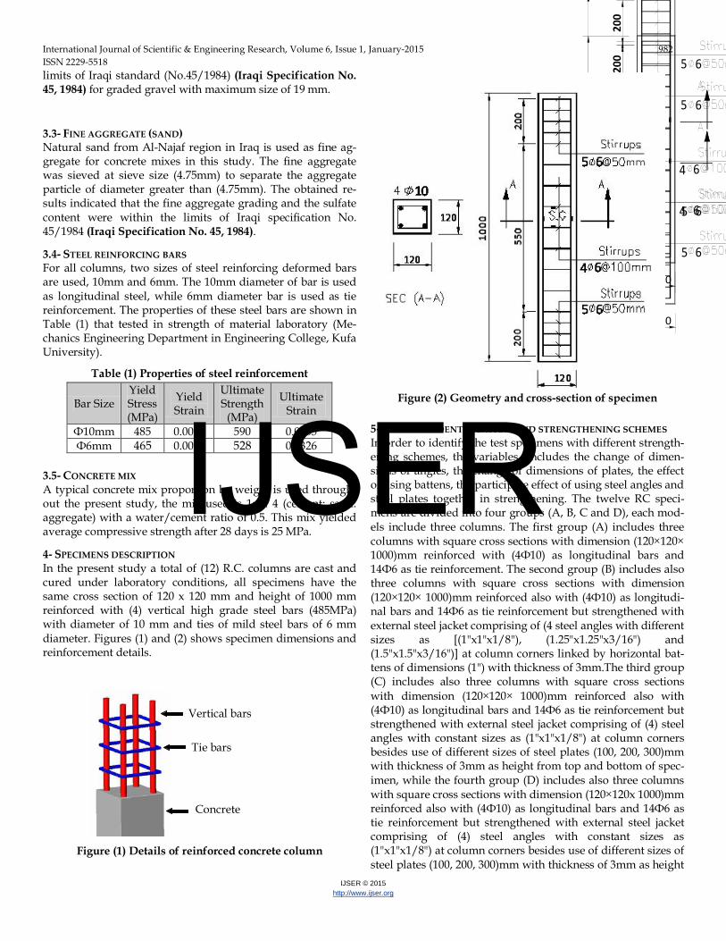
3.4- STEEL REINFORCING BARS For all columns, two sizes of steel reinforcing deformed bars are used, 10mm and 6mm. The 10mm diameter of bar is used as longitudinal steel, while 6mm diameter bar is used as tie reinforcement. The properties of these steel bars are shown in Table (1) that tested in strength of material laboratory (Me-chanics Engineering Department in Engineering College, Kufa University).
Table (1) Properties of steel reinforcement
Bar Size Yield Stress (MPa)
Yield Strain
Ultimate Strength
(MPa)
Ultimate Strain
Ф10mm 485 0.0025 590 0.0305 Ф6mm 465 0.0029 528 0.0326
3.5- CONCRETE MIX A typical concrete mix proportion by weight is used through-out the present study, the mix used is 1: 2: 4 (cement: sand: aggregate) with a water/cement ratio of 0.5. This mix yielded average compressive strength after 28 days is 25 MPa.
4- SPECIMENS DESCRIPTION In the present study a total of (12) R.C. columns are cast and cured under laboratory conditions, all specimens have the same cross section of 120 x 120 mm and height of 1000 mm reinforced with (4) vertical high grade steel bars (485MPa) with diameter of 10 mm and ties of mild steel bars of 6 mm diameter. Figures (1) and (2) shows specimen dimensions and reinforcement details.
Figure (1) Details of reinforced concrete column
10
120
120
6 5
6
6 4
5
120
20
0
550
200
10
00
10
120
120
6 5
6
6 4
5
120
20
0
550
200
10
00
bbbb
Figure (2) Geometry and cross-section of specimen
5- SPECIMEN IDENTIFICATION AND STRENGTHENING SCHEMES In order to identify the test specimens with different strength-ening schemes, the variables includes the change of dimen-sions of angles, the change of dimensions of plates, the effect of using battens, the participate effect of using steel angles and steel plates together in strengthening. The twelve RC speci-mens are divided into four groups (A, B, C and D), each mod-els include three columns. The first group (A) includes three columns with square cross sections with dimension (120×120× 1000)mm reinforced with (4Ф10) as longitudinal bars and 14Ф6 as tie reinforcement. The second group (B) includes also three columns with square cross sections with dimension (120×120× 1000)mm reinforced also with (4Ф10) as longitudi-nal bars and 14Ф6 as tie reinforcement but strengthened with external steel jacket comprising of (4 steel angles with different sizes as [(1"x1"x1/8"), (1.25"x1.25"x3/16") and (1.5"x1.5"x3/16")] at column corners linked by horizontal bat-tens of dimensions (1") with thickness of 3mm.The third group (C) includes also three columns with square cross sections with dimension (120×120× 1000)mm reinforced also with (4Ф10) as longitudinal bars and 14Ф6 as tie reinforcement but strengthened with external steel jacket comprising of (4) steel angles with constant sizes as (1"x1"x1/8") at column corners besides use of different sizes of steel plates (100, 200, 300)mm with thickness of 3mm as height from top and bottom of spec-imen, while the fourth group (D) includes also three columns with square cross sections with dimension (120×120x 1000)mm reinforced also with (4Ф10) as longitudinal bars and 14Ф6 as tie reinforcement but strengthened with external steel jacket comprising of (4) steel angles with constant sizes as (1"x1"x1/8") at column corners besides use of different sizes of steel plates (100, 200, 300)mm with thickness of 3mm as height
Concrete
Tie bars
Vertical bars
IJSER
International Journal of Scientific & Engineering Research, Volume 6, Issue 1, January-2015 983 ISSN 2229-5518
IJSER © 2015 http://www.ijser.org
from top and bottom of specimen linked by horizontal battens of dimensions (1") with thickness of 3mm.Table (2) illustrates the specimen identification system used based on the speci-men identification described above, Strengthening schemes are chosen carefully based on the practical needs and the field conditions.
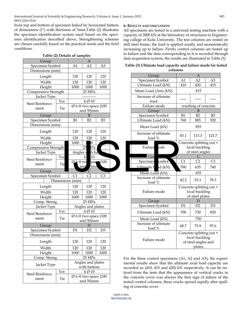
Table (2) Details of samples Group A
Specimen Symbol A1 A2 A3 Dimensions (mm):
Length 120 120 120 Width 120 120 120 Height 1000 1000 1000
Compressive Strength 25 MPa Jacket Type -----------
Steel Reinforce-ment
Ver. 4 Ø 10
Tie Ø 6 @ two space (100 and 50)mm
Group B Specimen Symbol B1 B2 B3 Dimensions (mm):
Length 120 120 120
Width 120 120 120 Height 1000 1000 1000
Compressive Strength 25 MPa Jacket Type Angles with battens
Steel Reinforce-ment
Ver. 4 Ø 10
Tie Ø 6 @ two space (100 and 50)mm
Group C Specimen Symbol C1 C2 C3
Dimensions (mm): Length 120 120 120 Width 120 120 120 Height 1000 1000 1000
Comp. Streng. 25 MPa Jacket Type Angles and plates
Steel Reinforce-ment
Ver. 4 Ø 10
Tie Ø 6 @ two space (100 and 50)mm
Group D Specimen Symbol D1 D2 D3 Dimensions (mm):
Length 120 120 120
Width 120 120 120 Height 1000 1000 1000
Comp. Streng. 25 MPa
Jacket Type Angles and plates with battens
Steel Reinforce-ment
Ver. 4 Ø 10
Tie Ø 6 @ two space (100 and 50)mm
6- RESULTS AND DISCUSSION All specimens are tested in a universal testing machine with a capacity of 2000 kN at the laboratory of structures in Engineer-ing college of Kufa University. The test columns are rested on stiff steel frame, the load is applied axially and monotonically increasing up to failure. Firstly control columns are tested up to failure and the data corresponding to it is recorded through data acquisition system, the results are illustrated in Table (3).
Table (3) Ultimate load capacity and failure mode for tested columns
Group A Specimen Symbol A1 A2 A3
Ultimate Load (kN) 410 420 415 Mean Load (Am) (kN) 415
Increase of ultimate load ----- ----- -----
Failure mode crushing of concrete Group B
Specimen Symbol B1 B2 B3 Ultimate Load (kN) 760 885 920
Mean Load (kN) 855
Increase of ultimate load % 83.1 113.3 121.7
Failure mode Concrete splitting out +
local buckling of steel angles
Group C Specimen Symbol C1 C2 C3
Ultimate Load (kN) 590 635 740 Mean Load (kN) 655
Increase of ultimate load % 42.2 53.1 78.3
Failure mode Concrete splitting out +
local buckling of steel plates
Group D Specimen Symbol D1 D2 D3
Ultimate Load (kN) 700 730 820
Mean Load (kN) 750 Increase of ultimate
load % 68.7 75.9 97.6
Failure mode
Concrete splitting out + local buckling
of steel angles and plates
For the three control specimens (A1, A2 and A3), the experi-mental results show that the ultimate axial load capacity are recorded as (410, 415 and 420) kN respectively. It can be no-ticed from the tests that the appearance of vertical cracks in the concrete cover was always the first sign of failure of the tested control columns, these cracks spread rapidly after spall-ing of concrete cover.
IJSER

International Journal of Scientific & Engineering Research, Volume 6, Issue 1, January-2015 984 ISSN 2229-5518
IJSER © 2015 http://www.ijser.org
At this stage the core of concrete carried the applied axial load because it is confined by the arching effect between the ties and longitudinal steel bars. At the end of this stage the ties will slip as the expansion of concrete core occurs. Figure (3) shows bar graph for ultimate load-carrying capacity of the control columns, while Figure (4) shows the failure pattern of one of control columns.
10
120
120
6 5
6
6 4
5
120
200
55
0
20
0
10
00
Figure (3) Ultimate load capacity of control columns
Figure (4) Failure pattern of control column
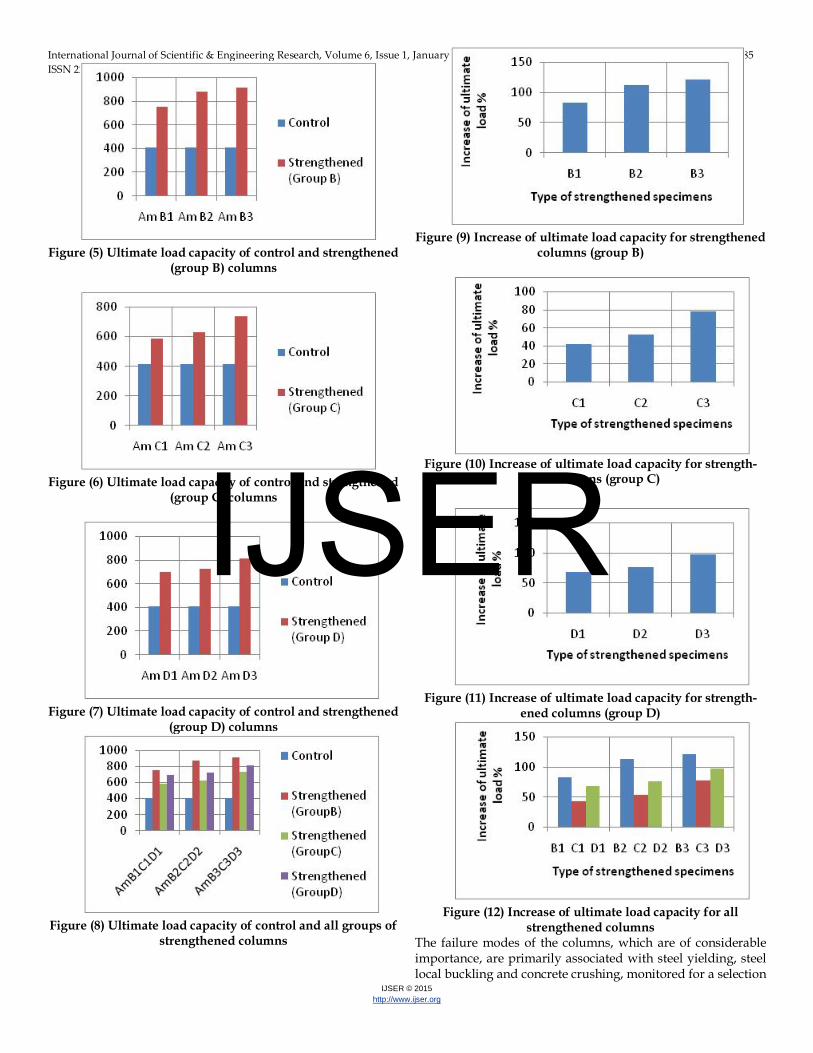
7- COMPARISON OF STRENGTHENED AND CONTROL COLUMNS The effect of strengthening the control columns by using ex-ternal steel jacket comprising of (4 steel angles with different sizes as [(1"x1"x1/8"), (1.25"x1.25"x3/16") and (1.5"x1.5"x3/16")] at column corners linked by horizontal bat-tens of dimensions (1") with thickness of 3mm is shown in Figure (5). It is observed from the experimental data and the corresponding bar graph that strengthening leads to increase in the ultimate load carrying capacity from (415kN) for the mean of control columns (Am), to (760kN), (885kN) and (920kN) for first group of strengthened columns (B1), (B2) and (B3) respectively. Thus there is an increase in ultimate loads as (83.1%) for (B1), (113.3%) for (B2) and (121.7%) for (B3) comparing with control column respectively.
Also the effect of strengthening the control columns by using external steel jacket comprising of (4) steel angles with con-stant sizes as (1"x1"x1/8") at column corners besides use of different sizes of steel plates (100, 200, 300)mm with thickness of 3mm as height from top and bottom of specimen is shown in Figure (6). It is observed from the experimental data and the corresponding bar graph that strengthening leads to increase in the ultimate load carrying capacity from (415kN) for the mean of control columns (Am), to (590kN), (635kN) and (740kN) for second group of strengthened columns (C1), (C2) and (C3) respectively. Thus there is an increase in ultimate loads as (42.2%) for (C1), (53.1%) for (C2) and (78.3%) for (C3) comparing with control column respectively. By similar the effect of strengthening the control columns by using external steel jacket comprising of (4) steel angles with constant sizes as (1"x1"x1/8") at column corners besides use of different sizes of steel plates (100, 200, 300)mm with thickness of 3mm as height from top and bottom of specimen linked by horizontal battens of dimensions (1") with thickness of 3mm is shown in Figure (7). It is observed from the experimental data and the correspond-ing bar graph that strengthening leads to increase in the ulti-mate load carrying capacity from (415kN) for the mean of con-trol columns (Am), to (700kN), (730kN) and (820kN) for third group of strengthened columns (D1), (D2) and (D3) respective-ly. Thus there is an increase in ultimate loads as (68.7%) for (D1), (75.9%) for (D2) and (97.6%) for (D3) comparing with control column respectively. Enhancement in the load carrying capacity of strengthened columns is mainly due to improvement in the strength of the confined concrete as shown in Figure (8), while Figures (9) to (12) explained that the increase in ultimate load capacity of strengthened columns comparing with control specimen. It is also conducted that using the steel-casing, the effective moment of inertia is increased and thus ductility demand will also be increased. The stiffening action of steel strip and angles enhanced the confined concrete strength. In this case, delay in the sudden compression failure of the strength columns oc-curs.
IJSER
International Journal of Scientific & Engineering Research, Volume 6, Issue 1, January-2015 985 ISSN 2229-5518
IJSER © 2015 http://www.ijser.org
Figure (5) Ultimate load capacity of control and strengthened
(group B) columns
Figure (6) Ultimate load capacity of control and strengthened
(group C) columns
Figure (7) Ultimate load capacity of control and strengthened
(group D) columns Figure (8) Ultimate load capacity of control and all groups of
strengthened columns
Figure (9) Increase of ultimate load capacity for strengthened
columns (group B)
Figure (10) Increase of ultimate load capacity for strength-
ened columns (group C)
Figure (11) Increase of ultimate load capacity for strength-ened columns (group D)
Figure (12) Increase of ultimate load capacity for all strengthened columns
The failure modes of the columns, which are of considerable importance, are primarily associated with steel yielding, steel local buckling and concrete crushing, monitored for a selection
IJSER
International Journal of Scientific & Engineering Research, Volume 6, Issue 1, January-2015 986 ISSN 2229-5518
IJSER © 2015 http://www.ijser.org
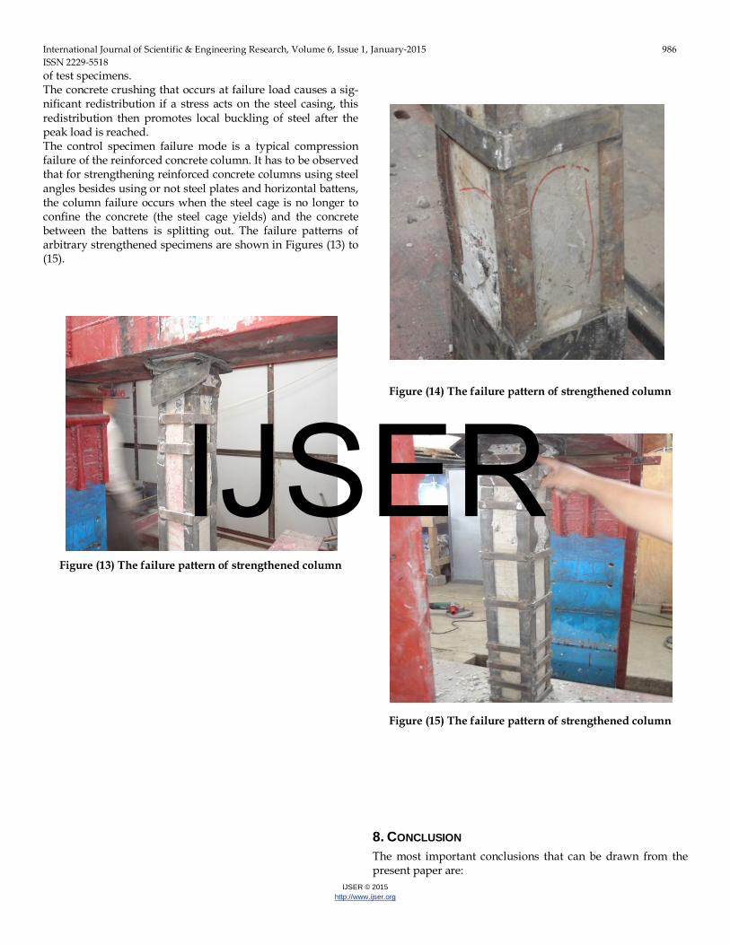
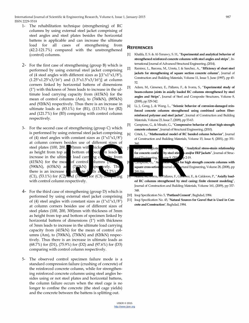
of test specimens. The concrete crushing that occurs at failure load causes a sig-nificant redistribution if a stress acts on the steel casing, this redistribution then promotes local buckling of steel after the peak load is reached. The control specimen failure mode is a typical compression failure of the reinforced concrete column. It has to be observed that for strengthening reinforced concrete columns using steel angles besides using or not steel plates and horizontal battens, the column failure occurs when the steel cage is no longer to confine the concrete (the steel cage yields) and the concrete between the battens is splitting out. The failure patterns of arbitrary strengthened specimens are shown in Figures (13) to (15).
Figure (13) The failure pattern of strengthened column
Figure (14) The failure pattern of strengthened column
Figure (15) The failure pattern of strengthened column
8. CONCLUSION The most important conclusions that can be drawn from the present paper are:
IJSER
International Journal of Scientific & Engineering Research, Volume 6, Issue 1, January-2015 987 ISSN 2229-5518
IJSER © 2015 http://www.ijser.org
1- The rehabilitation technique (strengthening) of RC columns by using external steel jacket comprising of steel angles and steel plates besides the horizontal battens is applicable and can increase the ultimate load for all cases of strengthening from (42.2-121.7%) compared with the unstrengthened (control) columns.
2- For the first case of strengthening (group B) which is performed by using external steel jacket comprising of (4 steel angles with different sizes as [(1"x1"x1/8"), (1.25"x1.25"x3/16") and (1.5"x1.5"x3/16")] at column corners linked by horizontal battens of dimensions (1") with thickness of 3mm leads to increase in the ul-timate load carrying capacity from (415kN) for the mean of control columns (Am), to (760kN), (885kN) and (920kN) respectively. Thus there is an increase in ultimate loads as (83.1%) for (B1), (113.3%) for (B2) and (121.7%) for (B3) comparing with control column respectively.
3- For the second case of strengthening (group C) which is performed by using external steel jacket comprising of (4) steel angles with constant sizes as (1"x1"x1/8") at column corners besides use of different sizes of steel plates (100, 200, 300)mm with thickness of 3mm as height from top and bottom of specimen leads to increase in the ultimate load carrying capacity from (415kN) for the mean of control columns (Am), to (590kN), (635kN) and (740kN) respectively. Thus there is an increase in ultimate loads as (42.2%) for (C1), (53.1%) for (C2) and (78.3%) for (C3) comparing with control column respectively.
4- For the third case of strengthening (group D) which is performed by using external steel jacket comprising of (4) steel angles with constant sizes as (1"x1"x1/8") at column corners besides use of different sizes of steel plates (100, 200, 300)mm with thickness of 3mm as height from top and bottom of specimen linked by horizontal battens of dimensions (1") with thickness of 3mm leads to increase in the ultimate load carrying capacity from (415kN) for the mean of control col-umns (Am), to (700kN), (730kN) and (820kN) respec-tively. Thus there is an increase in ultimate loads as (68.7%) for (D1), (75.9%) for (D2) and (97.6%) for (D3) comparing with control column respectively.
5- The observed control specimen failure mode is a standard compression failure (crushing of concrete) of the reinforced concrete column, while for strengthen-ing reinforced concrete columns using steel angles be-sides using or not steel plates and horizontal battens, the column failure occurs when the steel cage is no longer to confine the concrete (the steel cage yields) and the concrete between the battens is splitting out.
REFERENCES [1] Khalifa, E. S. & Al-Tersawy, S. H., “Experimental and analytical behavior of
strengthened reinforced concrete columns with steel angles and strips”, In-ternational Journal of Advanced Structural Engineering, (2014).
[2] Ramirez, L., Barcena, M., Urreta, I. & Sanchez, A., “Efficiency of short steel jackets for strengthening of square section concrete column”, Journal of Construction and Building Materials, Volume 11, Issue 5, June (1997), pp 45-52.
[3] Adam, M., Gimenez, E., Pallares, F., & Ivorra, S., “Experimental study of beam-column joints in axially loaded RC columns strengthened by steel angles and Strips”, Journal of Steel and Composite Structures, Volume 8, (2008), pp 329-342.
[4] Li, J., Gong, J., & Wang, L., “Seismic behavior of corrosion-damaged rein-forced concrete columns strengthened using combined carbon fiber-reinforced polymer and steel jacket”, Journal of Construction and Building Materials, Volume 23, Issue 7, (2009), pp 53-63.
[5] Campione, G., & Minafo, G., “Compressive behavior of short high strength concrete columns”, Journal of Structural Engineering, (2010).
[6] Critek, L., “Mathematical model of RC banded column behavior”, Journal of Construction and Building Materials, Volume 15, Issue 8, (2001), pp 351-360.
[7] Barga, F., Gigliotte, R., & Laterza, M., “Analytical stress-strain relationship for concrete confined by steel stirrups and/or FRP Jackets”, Journal of Struc-tural Engineering, Volume 9, (2006), pp 2-19.
[8] Campione, G., “Analytical model for high strength concrete columns with square cross-setion”, Journal of Structural Engineering, Volume 28, (2008), pp 295-316.
[9] Adam, M., Ivorra, S., Pallares, F., Gimenez, E., & Calderon, P., “Axially load-ed RC columns strengthened by steel casing: finite element modeling”, Journal of Construction and Building Materials, Volume 161, (2009), pp 337-348.
[10] Iraqi Specification No. 5, "Portland Cement", Baghdad, 1984. [11] Iraqi Specification No. 45, "Natural Sources for Gravel that is Used in Con-
crete and Construction", Baghdad, 1984.
IJSER


