REGIONAL DISTRICT OF - rdosmaps.bc.ca · ANSI American National Standards Institute . ASTM American...
78
SCHEDULE "A"
Transcript of REGIONAL DISTRICT OF - rdosmaps.bc.ca · ANSI American National Standards Institute . ASTM American...

SCHEDULE "A"


REGIONAL DISTRICT OF OKANAGAN-SIMILKAMEEN
SUBDIVISION SERVICING BYLAW NO. 2000, 2002 SCHEDULE "A"
Design Criteria, Specifications and Standard Drawings
TABLE OF CONTENTS 1.0 GENERAL INFORMATION ..........................................................................1
1.1 INTRODUCTION ...............................................................................1 1.2 DEFINITIONS ....................................................................................1 1.3 SCOPE AND USE .............................................................................2 1.4 NON-MUNICIPAL CODES AND STANDARDS .................................2
2.0 ROADS AND WALKWAYS .........................................................................4 2.1 GENERAL ..........................................................................................4
3.0 WATER SUPPLY .........................................................................................4 3.1 INTRODUCTION ...............................................................................4 3.2 DESIGN PARAMETERS ...................................................................5
3.2.1 Per Capita Flows, Fire Flow Demands .............................................................. 5 3.2.2 Pressure and Hydraulic Network Considerations .............................................. 6 3.2.3 Cover, Grades, Clearance .................................................................................. 7 3.2.4 Valving .............................................................................................................. 8 3.2.5 Hydrants ............................................................................................................ 8 3.2.6 Air Valves, Blow-Offs ...................................................................................... 9 3.2.7 Thrust Blocking ................................................................................................. 9 3.2.8 Service Connections .......................................................................................... 9 3.2.9 List of Standard Drawings ................................................................................. 10 3.2.10 Private Water Source ......................................................................................... 10
3.3. MATERIALS ......................................................................................12 3.3.1 Pipe .................................................................................................................... 12 3.3.2 Pipe Joints ......................................................................................................... 12 3.3.3 Valves, Valve Boxes and Fittings ..................................................................... 13 3.3.4 Hydrants ............................................................................................................ 14 3.3.5 Service Connections .......................................................................................... 14 3.3.6 Pipe Bedding ..................................................................................................... 15
3.4 INSTALLATION .................................................................................16 3.4.1 Excavation, Bedding, Backfill, Restoration ...................................................... 16 3.4.2 Pipe Laying ....................................................................................................... 16
Contents -1

TABLE OF CONTENTS - (Cont'd)
3.4.3 Valves, Hydrants and Appurtenances ............................................................... 17 3.4.4 Thrust Blocking ................................................................................................. 17 3.4.5 Service Connections .......................................................................................... 17 3.4.6 Testing ............................................................................................................... 18 3.4.7 Flushing and Disinfection ................................................................................. 18
4.0 SANITARY SEWERS ...................................................................................19 4.1 INTRODUCTION ...............................................................................19 4.2 DESIGN PARAMETERS ...................................................................19
4.2.1 Design Flows ..................................................................................................... 19 4.2.2 Pipe Flow Formulas .......................................................................................... 20 4.2.3 Manholes and Hydraulic Losses ........................................................................ 20 4.2.4 Temporary Cleanouts ........................................................................................ 21 4.2.5 Minimum Pipe Diameter, Velocity, Grades and Cover .................................... 22 4.2.6 Service Connections .......................................................................................... 23 4.2.7 Pumping Stations and Force Mains ................................................................... 23 4.2.8 List of Standard Drawings ................................................................................. 25
4.3 MATERIALS ......................................................................................25 4.3.1 Gravity Main Pipe ............................................................................................. 25 4.3.2 Force Main Pipe ................................................................................................ 26 4.3.3 Pipe Joints ......................................................................................................... 26 4.3.4 Manholes ........................................................................................................... 26 4.3.5 Temporary Cleanouts ........................................................................................ 26 4.3.6 Service Connections .......................................................................................... 26 4.3.7 Pipe Bedding ..................................................................................................... 27
4.4 INSTALLATION .................................................................................27 4.4.1 Excavation, Bedding, Backfill, Restoration ...................................................... 27 4.4.2 Pipe Laying ....................................................................................................... 27 4.4.3 Manholes, Cleanouts, and Appurtenances......................................................... 27 4.4.4 Service Connections .......................................................................................... 28 4.4.5 Flushing and Testing ......................................................................................... 28
5.0 STORM DRAINAGE ....................................................................................29 5.1 INTRODUCTION ...............................................................................29 5.2 DESIGN PARAMETERS ...................................................................29
5.2.1 Design Methods and Flows ............................................................................... 29 5.2.2 Flow Capacities for Storm Sewers and Open Channels: ................................... 30 5.2.3 Minimum Pipe Diameters, Velocities and Cover .............................................. 31 5.2.4 Manholes and Catch Basins .............................................................................. 31 5.2.5 Inlet and Outlet Structures ................................................................................. 32 5.2.6 Ditches ............................................................................................................... 33 5.2.7 Service Connection ........................................................................................... 33 5.2.8 Trench Drains and Drywells .............................................................................. 33 5.2.9 Natural Watercourses ........................................................................................ 34 5.2.10 List of Standard Drawings ................................................................................. 34
5.3 MATERIALS ......................................................................................34
Contents - 2

TABLE OF CONTENTS - (Cont'd)
5.3.1 Pipe .................................................................................................................... 34 5.3.2 Pipe Joints ......................................................................................................... 35 5.3.3 Manholes ........................................................................................................... 35 5.3.4 Catch Basins ...................................................................................................... 35 5.3.5 Inlet and Outlet Structures ................................................................................. 35 5.3.6 Service Connections .......................................................................................... 36
5.4 INSTALLATION .................................................................................36 5.4.1 Excavation, Bedding, Backfill, Restoration ...................................................... 36 5.4.2 Pipe Laying ....................................................................................................... 36 5.4.3 Manholes, Catch Basin and Appurtenances ...................................................... 36 5.4.4 Service Connections .......................................................................................... 36 5.4.5 Flushing and Testing ......................................................................................... 36 5.4.6 Ditching ............................................................................................................. 37
6.0 STREET LIGHTING .....................................................................................38 6.1 INTRODUCTION ...............................................................................38 6.2 DESIGN PARAMETERS ...................................................................38
6.2.1 Minimum Levels of Illumination ...................................................................... 38 6.2.2 Pole Locations ................................................................................................... 39 6.2.3 Underground Ducting Locations ....................................................................... 40 6.2.4 Lamp Standards and Luminaires ....................................................................... 40 6.2.5 List of Standard Drawings ................................................................................. 41
6.3 MATERIALS ......................................................................................41 6.3.1 Poles .................................................................................................................. 41 6.3.2 Pole Bases ......................................................................................................... 41 6.3.3 Conduit .............................................................................................................. 41 6.3.4 Grounding .......................................................................................................... 41 6.3.5 Conductors ........................................................................................................ 42 6.3.6 Connectors ......................................................................................................... 42 6.3.7 Luminaires ......................................................................................................... 42 6.3.8 Lamps ................................................................................................................ 42 6.3.9 Conduit Bedding ............................................................................................... 42 6.3.10 Junction Boxes .................................................................................................. 43 6.3.11 Service Panels ................................................................................................... 43 6.3.12 Photo-Cell Units ................................................................................................ 43 6.3.13 Ground Rods ..................................................................................................... 43 6.3.14 Paint ................................................................................................................... 43
6.4 INSTALLATION .................................................................................44 6.4.1 Layout and Positioning ...................................................................................... 44 6.4.2 Conduit Installation ........................................................................................... 44 6.4.3 Poles, Bases and Luminaires ............................................................................. 44 6.4.4 Wiring and Equipment ...................................................................................... 44 6.4.5 Inspection and Testing....................................................................................... 45 6.4.6 Installation on Power Utility Poles .................................................................... 45
7.0 NON-MUNICIPAL UTILITIES .......................................................................46
Contents - 3

TABLE OF CONTENTS - (Cont'd)
Contents - 4
7.1 INTRODUCTION ...............................................................................46 7.2 NATURAL GAS .................................................................................46 7.3 POWER .............................................................................................46 7.4 TELEPHONE AND CABLEVISION ....................................................46
8.0 STANDARD DRAWINGS ............................................................................47 8.1 GENERAL NOTES ............................................................................47 8.2 LIST OF STANDARD DRAWINGS ....................................................48

REGIONAL DISTRICT OF OKANAGAN-SIMILKAMEEN
SUBDIVISION SERVICING BYLAW NO. 2000, 2002
SCHEDULE "A"
1.0 GENERAL INFORMATION
1.1 INTRODUCTION
Schedule "A" to the Subdivision Servicing Bylaw identifies the Design Criteria, Specifications, and Standard Drawings acceptable to the Regional District.
This Schedule is to be referred to in the design, construction and acceptance of Engineering Works within the Regional District. Additional information, clarification and suggestions for changes and amendments should be directed to:
Regional District of Okanagan-Similkameen 101 Martin Street Penticton, B.C. V2A 5J9
1.2 DEFINITIONS
In this Schedule, unless the context otherwise specify:
"ACCEPTED" means as accepted by the Local Authority and the Ministry of Transportation Approving Officer.
"CONSIDERED" means considered for acceptance by the Local Authority.
"CONTRACTOR" means the person or persons or the company undertaking the construction of works in a subdivision development, and/or on municipal property, or their employees, subcontractors or other duly authorized representative.
Page 1

"DEVELOPER" means the owner of land or the holder of a bona-fide interim agreement or option to purchase land, who has made application to the Regional District for or is engaged in undertaking the development or subdivision of such land and shall include his duly authorized representative.
"DEVELOPER'S ENGINEER" means the Professional Engineer engaged by the Developer to design and/or prepare drawings for the construction of works in a subdivision, development, and/or on municipal property, or his duly authorized representative.
"ENGINEER" means the Engineer of the Local Authority or a duly authorized representative of the Regional District of Okanagan-Similkameen. "PROFESSIONAL ENGINEER" means a person who is registered or duly licensed as such in British Columbia under the provision of the Engineers and Geoscientists Professional Act.
"REGIONAL DISTRICT" means the Regional District of Okanagan-Similkameen.
"THIS SCHEDULE" means the "Design Criteria, Specifications and Standard Drawings" prepared by the Regional District of Okanagan-Similkameen.
"THE WORK" means and includes anything and everything to be done for the setting out, the execution and fulfilment of the requirements in this Schedule.
1.3 SCOPE AND USE
This schedule shall be taken to mean the Design Criteria, Specifications and Standard Drawings to be referred to, and incorporated in, subdivisions, developments, and on municipal properties or rights-of-way, in the Regional District of Okanagan-Similkameen.
1.4 NON-MUNICIPAL CODES AND STANDARDS
Where non-Municipal codes and standards, such as A.S.T.M., C.S.A., A.W.W.A., etc., are referred to in this Schedule, the latest adopted revision, including amendments, of these codes and standards at the date of commencement of construction shall apply, except that the Approving Officer may vary requirements under certain circumstances in the interest of public health or safety.
When references to the following capitalized abbreviations are made, they refer to Specifications, Standards, or Methods of the respective Association.
Page 2

Page 3
AASHTO American Association of State Highway and Transportation Officials ANSI American National Standards Institute ASTM American Society for Testing and Materials AWWA American Water Works Association AWS American Welding Society BCBC British Columbia Building Code CEC Canadian Electrical Code CEMA Canadian Electrical Manufacturers Association CGSB Canadian General Standards Board CSA Canadian Standards Association CSPI Corrugated Steel Pipe Institute IES Illumination Engineering Society LEMA Lighting Equipment Manufacturers Association NBC National Building Code of Canada NEC National Electrical Code NEMA National Electrical Manufacturers Association NESC National Electric Safety Code NFPA National Fire Protection Association TAC Transportation Association of Canada WCB Workers' Compensation Board

2.0 ROADS AND WALKWAYS
2.1 GENERAL
The design and construction of roads and walkways shall conform to current standards of the Ministry of Transportation. Information regarding these standards can be obtained from the Local District office of the Ministry of Transportation.
Notwithstanding the standards of the Ministry of Transportation, the following shall also apply:
1. Driveways accessing a parcel of land shall be constructed at or near a right
angle (70o - 110o) to the road and at a maximum grade of 2% for the first 5 metres. Driveway grades shall not exceed 8% within the right-of-way and 10% from property line to the building site or as approved by the Ministry of Transportation.
2. No more than 2 (two) contiguous panhandles on abutting parcels shall be
permitted. 3. No fee simple subdivision shall be permitted with access by common lot.
3.0 WATER SUPPLY
3.1 INTRODUCTION
Water distribution design and construction shall conform to the requirements of the relevant Local Authority and this schedule.
The system shall be designed to provide day-to-day requirements and also shall provide adequate flows for fire protection. The required flow shall be the sum of the maximum daily flow plus the required fire flow.
Page 4

When a private water source is required for land development, the private water source must meet the requirements of Section 3.2.10 of this bylaw.
3.2 DESIGN PARAMETERS
3.2.1 Per Capita Flows, Fire Flow Demands
Minimum design flows for domestic demand shall be:
Maximum daily domestic flow 8,000 l/single family unit/day Peak hour domestic flow 13,600 l/single family unit/day
Additional design flows may be required for industrial, institutional or commercial developments and the Local Authority will review design flows for other developments and larger lot sizes.
Fire flow shall be in accordance with the criteria outlined in "Water Supply for Public Fire Protection - A Guide to Recommended Practice", published by Fire Underwriter's Survey.
Notwithstanding the above, the following minimum fire flows shall be met for the noted development types:
Provisions in Section 3.2.1 deleted and substituted “Single and Two Family Residential” by authority of Bylaw No. 2000.02, 2008 adopted June 19, 2008
Zone Required Fire Flow Single and Two Family Residential 60 litres/sec Multiple Family Residential 150 litres/sec Commercial 260 litres/sec Industrial 230 litres/sec Institutional 85 litres/sec
Provisions in Section 3.2.1 deleted “rural area fire flow” by authority of Bylaw No. 2000.02, 2008 adopted June 19, 2008
Design populations used in calculating water demand shall be computed in accordance with the Regional Districts's population predictions or with the planned development in the area to be served, whichever is larger.
Page 5

3.2.2 Pressure and Hydraulic Network Considerations
Water Pressure: Unless otherwise accepted by the Local Authority, the following standards shall be used:
Minimum pressure at peak hour demand 265 kPa (40 psi)
Maximum allowable pressure 620 kPa (90 psi)
865 kPa (125 psi) with individual PRV's.
Minimum fire protection residual 140 kPa (20 psi) (at hydrant, maximum day demand)
As a basic guideline, the following criteria may be used:
Design for maximum of (a) fire flows plus maximum day demand or (b) peak hour demand, whichever is greater.
Hazen Williams formula to be used.
Demand requirements shall be based on the Regional District's present water consumption records and the projected trends. Demand may vary for different locations within the Regional District.
Where there is an existing hydraulic network in place, the Local Authority may provide information for design calculations.
Depending on the complexity and extent of the proposed distribution system, the Local Authority may require a hydraulic analysis design showing minimum flows and pressures.
The maximum desirable length of any permanent non-interconnected watermain shall be 150 m. All mains exceeding 150 m, unless it is a temporary situation, shall be looped unless otherwise accepted. Dead-end mains shall not be promoted.
Watermains are to be extended to the last property line at the end of a road which can be further extended and to a least 1 m beyond the curb line or edge of pavement at the extreme end of a designed cul-de-sac.
Page 6
In residential areas, watermains servicing fire hydrants shall be 150 mm diameter or larger. Watermains 100 mm in diameter may be permitted for domestic service on dead end roads where no further extension is planned, no fire hydrant is required and the dead end main is less than 75 m long. Where a dead-end main is longer than 200 m or services more than one hydrant, watermain shall be 200 mm diameter or larger. In commercial/industrial/ institutional areas, the minimum watermain size shall be 200 mm diameter. However, should the hydraulic analysis indicate a need for larger size watermains, the larger size watermain shall be used.
Watermains shall generally be located in local road right of way's as shown on the Standard Drawings and must be accepted by the Ministry of Transportation. Permits to be issued by the Ministry of Transportation to Utility Company on completion. When watermains must cross private property, a registered utility right-of-way, minimum 6.0 m wide, shall be provided.
Design of pumping stations and control valving such as pressure reducing valves require the acceptance of the Local Authority. Good engineering practice and consideration of operation and maintenance requirements should be considered in the design of these facilities.
3.2.3 Cover, Grades, Clearance
The minimum cover over any watermain shall be 1.6 metres unless otherwise required.
The minimum grade for a main shall be 0.1%. The maximum grade shall be 30.0% unless provisions are made to anchor the pipe to the bottom of the trench with concrete poured in place or with restrained joints. Watermain grades shall generally be consistent with the roadway grade.
The minimum horizontal clearance between a watermain and any sewer shall be 3.0 m unless the watermain is concrete encased or installed in a carrier pipe.
The minimum vertical clearance at a crossing between a watermain and any sanitary sewer shall be 450 mm unless the watermain is adequately encased in concrete. The minimum vertical clearance to piping other than sanitary sewer shall be 300 mm unless the watermain is adequately encased in concrete.
Page 7

3.2.4 Valving
In general, valves shall be located as follows:
a) In intersections, in a cluster at the pipe intersection or at the projection of property lines, to avoid conflicts with curbs and sidewalks:
i) 3 valves at "X" intersection ii) 2 valves at "T" intersection
so that specific sections of mains may be isolated.
b) Not more than 240 m apart for single family residential. All other zones
shall require special designs.
c) Not more than 1 hydrant isolated.
d) In gravel surfaced roads, outside the travelled portion of the roadway with valve boxes set 25 mm lower than the roadway surface.
Valves shall be the same diameter as the main up to 300 mm diameter.
3.2.5 Hydrants
Fire hydrants shall generally be located at street intersections. Where hydrants are required at mid-block locations, they shall be installed opposite property pins at an offset to facilitate road maintenance and as shown on the Standard Drawings. In general, all above ground utilities must be located outside the ditch x-section or outside curb. In no case shall fire hydrant spacing exceed a distance of 250 m nor should any residence be more than 300 m from a hydrant.
In high density residential, commercial, and industrial areas, hydrants shall be located at a maximum spacing of 150 m or as accepted. Additional hydrants may be required in high risk areas.
It shall be the Developer's responsibility to ensure the design and proposed locations of the fire hydrants will not conflict with existing or proposed street lights, power poles, etc. All hydrant locations and hydrant type, design and specification are to be confirmed with local Fire Departments.
All hydrants shall be installed with the pumper port facing the street and in no case shall the port be less than 450 mm above ground level.
Gate valves shall be installed with a flanged connection at the main to isolate all hydrants.
Page 8

3.2.6 Air Valves, Blow-Offs
Air release valves shall be installed at the summit of all mains of 150 mm diameter and larger except where the difference in grade between the summit and valley is less than 300 mm. Chamber insulation and drainage shall conform to Standard Drawings.
A 50 mm diameter standpipe shall be installed on all dead-end mains. Blow-offs shall be installed in a box below grade and shall not be located in the travelled portion of the roadway.
3.2.7 Thrust Blocking
Concrete thrust blocking shall be provided at bends, tees, wyes, reducers, plugs, caps, and blow-offs. The area of thrust block bearing on pipe and ground shall be as shown on the standard drawings or as accepted. For mains 300 mm diameter and larger or in areas of poor soils, special designs may be required.
3.2.8 Service Connections
In addition to the Local Authority requirements, service connections shall be subject to the requirements of the BC and National Plumbing Codes. Service connections larger than 50 mm in diameter may be installed using a gate valve flanged to the tee at the main and, temporary cap and thrust block at property line. Service connections 19 mm to 50 mm diameter shall include a corporation stop at the main, a service saddle as accepted, and a curb stop and valve box at the property line.
The minimum size water service connections shall be as follows:
Residential 19 mm diameter Other 25 mm diameter.
Whenever possible all water service connections shall be located at 1.5 m from the lowest lot corner or as accepted by the Local Authority.
Connections shall be installed up to the property line at a minimum depth of 1.5 m. All services shall be marked with a 40 mm x 90 mm stake at the property line with the top 150 mm painted blue and marked with the length of the stake in meters. Curb stops shall be located at a 300 mm offset from property line and the curb boxes shall be extended to ground level.
Page 9

3.2.9 List of Standard Drawings
Title No. 19 mm Standard Water Service Detail W1 32 mm/50 mm6/Standard Water Service Detail W2 Valve Box Detail W3 Hydrant Detail W4 Standard Water Main Blow-Off W5 Thrust Block Details W6 Air Valve Chamber Detail W7 Local Urban Road - Typical Location of Utilities G1 Local Urban Road - Open Shoulders G2 Trench Detail S2 Trench Bedding Details S6
3.2.10 Private Water Source
Provisions in Section 3.2.10 above Section 3.2.10.1 deleted and substituted with the following by authority of Bylaw No. 2189, adopted June 19, 2003
If there is no community water system, each parcel to be created by the subdivision that does not have an existing well located on the parcel, that produces potable water, must have a source of at least 2,300 litres per day of potable water having a flow capacity of at least 20 litres per minute for one hour. The responsibility for ascertaining whether the requirements for quality and for quantity, including rate of flow, of water from a private water source are satisfied is solely that of the owner of the land being subdivided. The Regional District does not inspect quality or quantity of water from private sources, nor does compliance with this bylaw in respect of quality or quantity of potable water warrant or guarantee the continuing quality or quantity of water over time. .1 Requirements of Wells:
a) A water well must be constructed on each parcel of a proposed
subdivision that is dependent upon groundwater as a source of water.
b) A well is restricted to supplying water to the parcel it serves.
Page 10

Sub-section 3.2.10.1 (c) deleted by authority of Bylaw No. 2189, adopted June 19, 2003. c) Deleted by authority of Bylaw No. 2189.
d) All wells must be drilled and cased.
e) All wells must be constructed in such a way as to prevent surface
water from entering the well.
Sub-section 3.2.10.2 and 3.2.10.3 deleted by authority of Bylaw No. 2189, adopted June 19, 2003.
Page 11

3.3. MATERIALS
3.3.1 Pipe
The materials outlined in Table 3.3.1 on the following page shall be considered acceptable for installation throughout the Regional District.
Table 3.3.1 - Pipe Materials and Specifications
MATERIAL SIZE RANGE (mm)
SPECIFICATIONS USE
soft copper 19 - 50 ASTM, B88, Type K service connection
polyethylene** 19 - 50 CSA, B137-01, 160 Series, Med. density
service connection
polyvinyl chloride
100 - 900 AWWA C900, C905 Class 150 (bell & spigot joints)
distribution mains and service connections
ductile iron* 300 and larger
AWWA C151 cement mortar lined C104 rubber gasket on mechanical joints C111
distribution and trunk mains
*Corrosion protection must be considered ** As approved by Local Authority
Consideration may be given to use of alternate materials for major trunk mains or where main pressures exceed 750 kPA (110 psi).
3.3.2 Pipe Joints
Jointing of pipe shall be in accordance with manufacturer's recommendations.
A flexible joint shall be provided at locations where pipe is held in a fixed position by a rigid structure or support.
Unless otherwise approved, the amount of pipe deflection at joints and couplings shall not exceed 3 degrees, or one half the limit specified by the manufacturer, whichever is less.
Page 12

3.3.3 Valves, Valve Boxes and Fittings
Solid wedge gate valves, resilient seat, iron body, bronze mounted, clockwise closure, manufactured in Canada, with non-rising stems, conforming to A.W.W.A. C500 specifications and combined with extension spindles and valve boxes shall be installed on all watermains up to and including 300 mm diameter and may be installed on 300 mm diameter water mains. Valve manufacturer must be acceptable to the Local Authority.
Where air release valves are required they shall be double acting, vacuum type, with cast iron bodies and 860 KPa flanges. A ball valve or gate valve with activator shall be installed beneath each air valve assembly. All air release valves shall be protected from frost by insulating the valve chambers.
Valve boxes shall be Terminal City NT Type 1 or equal, or as approved. Valve box risers shall be PVC C-900 pipe or as approved, suitable for the valve and valve box. Fittings for PVC pipe shall be: a) Cast iron fittings manufactured to AWWA C110 designed for a working
pressure of 1035 kPa.
b) Asphalt coated ductile iron compact fittings manufactured to ANSI/AWWA C153/A21.53-84.
Mechanical seal joints on fittings to pipe shall be formed by a bell and preformed rubber gasket suitable for the pipe to which the joint is made.
Flanged joints on fittings shall be flat faced conforming in dimension and drilling to ANSI B16.1.
Ends shall be flanged or belled to suit pipe ends.
Page 13

3.3.4 Hydrants
Hydrants shall be compression type Canada Valve "Century" Model or Terminal City Model C-71P or approved equal and shall conform with A.W.W.A. Specification C502 and shall be flanged at 50 mm above the ground line. Hydrants shall have two hose nozzles and one pumper nozzle complete with caps. Hose nozzles shall be 63 mm (2.5 inches) in diameter and pumper nozzles 100 mm (4 inches) in diameter. Nozzle threads shall conform with British Columbia Fire Hose Thread Specification, 8 threads per inch on hose port and 4 threads per inch on the pumper port.
Hydrant stems shall be turned counterclockwise to open. Stem seals shall be resilient "O-Ring".
Hydrant extensions shall be supplied complete with nuts, bolts, flange gaskets, operator extension and coupling.
Hydrants shall be supplied complete with nuts, bolts, flange gaskets, operator extension and coupling.
Hydrants shall be installed using hub joints and shall be held in place by tie rods. Thrust blocks shall be installed for thrust restraint in addition to tie rods.
3.3.5 Service Connections
Corporation stops shall be in accordance with AWWA C800, with fittings ends suitable for use with compression fittings. For 19 mm dia. Mueller H-15028 or Ford F-1100 unless otherwise accepted; for 50 mm dia. Ford FB 1100 unless otherwise accepted. Service saddles for connections to PVC shall be wide-band stainless steel complete with cadmium-plated bolts and existing A.C. shall be double strap type.
Corporation couplings shall be in accordance with AWWA C800.
Copper pipe with compression type fittings shall be used for all connections up to 50 mm diameter and polyvinyl chloride with fittings in accordance with Section 3.3.3 for connections 100 mm diameter and larger. 50 mm diameter connections may be silver soldered. Service connections between 50 mm and 100 mm in diameter shall not be permitted.
19 mm curb stops shall be Mueller H15219 or Ford B44-333 or as accepted, with drain; 50 mm curb stops shall be Ford B41-777 with drain, or as accepted. Curb boxes shall be adjustable type, Trojan or Terminal City, and have a sidewalk pattern top casting. Stationary rods shall be provided.
Page 14

3.3.6 Pipe Bedding
Pipe bedding specifications shall conform to Local Authority standards for Class "A" or, Class "B". Pipe bedding selection may vary for different material installed and for different locations within the Regional District.
Page 15

3.4 INSTALLATION
3.4.1 Excavation, Bedding, Backfill, Restoration
Any excavation in an existing road Right-of-Way shall be under permit from Ministry of Transportation and all installation and compaction must be to Ministry of Transportation Standards. All utilities in a new subdivision must also be approved and eventually permitted by the Authority having jurisdiction.
The trench shall be excavated so that pipe can be laid to the specified alignment and depth with allowance for the specified trench wall clearances and bedding. Wall clearances shall be minimum 150 mm, maximum 400 mm, from the bottom of the trench to 100 mm above the top of the pipe.
Bracing, sheeting and trench side slopes shall be in accordance with Worker's Compensation Board safety requirements. Dewatering may be required to control trench water.
Bedding material shall be sand, or concrete. Bedding shall be compacted to 95% Standard Proctor Density.
Backfill material shall be approved select native material or pitrun gravel and shall be placed in such a manner to prevent damage to the pipe.
Backfill materials in travelled surfaces shall be compacted to 95% Standard Proctor Density, except for the upper 750 mm which shall be compacted in accordance with the adjacent travelled surface design requirements.
Surface restoration shall conform to the original condition or better, or as accepted by the Ministry of Transportation where applicable.
3.4.2 Pipe Laying
Pipe shall be installed in accordance with the applicable AWWA specifications, the manufacturer's recommendations and requirements of this Schedule.
Page 16

Pipes shall be handled with the greatest care and with equipment designed so that no damage occurs to pipe or fittings. All pipes shall be laid to horizontal line, with a tolerance of plus or minus 10 mm of the design line; and grade, with a tolerance of plus or minus 25 mm for water mains and services. The pipes shall be jointed in accordance with the manufacturer's recommendations except that joint deflections shall be allowed only up to one-half of the manufacturer's recommended tolerances. Particular care must be taken to see that the ends of the pipes are kept clean. Care shall be taken to properly align the pipe once the joints are forced home. Movement of the pipe once the joints is made shall be kept to an absolute minimum. Jumping on or dropping of pipe to obtain grade shall not be permitted.
Care shall be taken to prevent the entrance of trench water or other material into the pipe during installation.
3.4.3 Valves, Hydrants and Appurtenances
Valves shall be installed at the specified locations, in the vertical position. Valve boxes shall be installed plumb, centred over the valve, and such that traffic loads are not transmitted to the valve.
Hydrants shall be installed at the specified locations, set plumb and such that the pumper port faces, and is at right angles to, the road centreline, unless otherwise accepted. Drain outlets with drain rock shall be provided and kept free of obstructions. The ground flange shall be 50 mm above finished ground or sidewalk grade unless otherwise accepted.
Fittings shall be installed at the specified locations in accordance with the manufacturer's recommendations.
3.4.4 Thrust Blocking
Thrust block bearing areas shall be to Local Authority standards. Concrete shall be 25 MPa minimum at 28 days.
Care shall be taken to ensure that concrete does not interfere with the operation of flange bolts and nuts or prevent proper operation of hydrant drains.
3.4.5 Service Connections
Service connections shall be installed at the specified locations and depths with the same tolerances as specified for pipe laying.
Page 17

Curb stop boxes shall be set plumb and adjusted to finish grade.
3.4.6 Testing
Prior to testing, all new water mains are to be cleaned of debris by flushing and immediately afterwards the pipe ends shall be capped in preparation for testing and disinfection. All water mains shall be tested in accordance with the appropriate AWWA specifications and the following criteria:
a) The test pressure shall be 1035 kPa or 1.5 times the operating pressure,
whichever is greater. The pressure test shall be maintained for a minimum of two hours.
b) The allowable leakage shall be determined by AWWA formula:
L = N D P0.5 L = allowable leakage in litres per hour 131,000
N = number of joints in test section
D = inside diameter of pipe in millimetres P = test pressure in kilopascals
Service connections shall be tested with the watermain.
The Local Authority shall be notified 24 hours in advance of the leakage testing and may elect to witness the test. All test data and leakage calculations duly certified by a Professional Engineer are to be submitted to the Local Authority.
3.4.7 Flushing and Disinfection
All water mains shall be disinfected by chlorination, after the system has been flushed of dirt and other debris. Chlorination methods shall conform A.W.W.A. C601 and all disinfection shall be acceptable to the Local Authority and Public Health Inspector.
Upon completion of disinfection, the entire piping system shall be thoroughly flushed, filled with water and left in a condition ready for use.
Page 18

Care shall be taken to ensure chlorinated water from the testing procedure is not discharged into fish bearing streams. Dechlorination may be required prior to discharge.
4.0 SANITARY SEWERS
4.1 INTRODUCTION
Sanitary sewer systems shall be designed and installed in accordance with the requirements of the B.C. Ministry of Environment, Waste Management Branch, "Guidelines for Assessing Sewage Collection Facilities", and the requirements noted in this Schedule.
4.2 DESIGN PARAMETERS
4.2.1 Design Flows
The sanitary sewer system shall be designed using the following minimum average daily flows for the zone noted:
Residential/institutional = 450 litres/capita/day
An infiltration rate of 30,000 litres/day/km of sewer main shall be added to the above flows.
The design flows shall be calculated using the peak daily flows plus the infiltration rate.
Peak flows shall be 4 times the average daily flow for contributing areas with populations less than 1,000; and 3.5 times the average daily flow for contributing areas with populations between 1,000 and 3,000. For populations of more than 3,000 persons, following the formula:
M = 1 + 14 shall be used. 4 + P 0.5
Where: M = ratio of peak to average flow
P = population in thousands
Page 19

Design populations used in calculating average daily flows shall be computed in accordance with the Local Authority's population predictions or with the planned development in the area to be served, whichever is larger.
4.2.2 Pipe Flow Formulas
Capacities of gravity sanitary sewer mains shall be determined using Mannings' Formula: Calculations for capacities of sanitary sewer forcemains shall use the Hazen - Williams Formula:
4.2.3 Manholes and Hydraulic Losses
Manholes on Community Sanitary Sewer mains shall be required at:
• all changes in grade • all changes in direction • all changes in pipe sizes • all intersecting sewers • all terminal sections • downstream end of curvilinear sewers
Manholes shall be placed where future extensions are anticipated and shall be spaced no greater than 100 m apart. Manholes should not be located in wheel paths.
Pipe intersections in manholes shall utilize smooth hand formed concrete channels to maintain uniform flows.
The invert of the downstream pipe shall not be higher than that of the upstream pipe.
The springline of the downstream pipe shall not be higher than that of the upstream pipe.
Sanitary sewer mains are to be extended to the last property line of the area it serves, with the exception of sanitary sewer mains in cul-de-sacs where they shall terminate at or near the centre of the cul-de-sac with a manhole.
Minimum drop in invert levels across manholes:
i) Straight run or deflections up to 45° - 30 mm drop
Page 20

ii) Deflections 45° to 90° - 60 mm drop
A drop pipe shall be installed when the drop between inverts exceeds 0.6 m.
Inside ramps will be permitted up to 450 mm from invert to channel bed.
Where a small pipe joins a larger pipe, the energy gradient shall be maintained through the transition.
Deep manholes shall be provided with safety platforms in accordance with the British Columbia Workers' Compensation Board requirements.
Precast concrete manhole sections shall conform to ASTM C478 and shall be minimum 1050 mm diameter for mains less than 450 mm diameter, and minimum 1200 mm diameter for mains greater than 450 mm diameter.
4.2.4 Temporary Cleanouts Temporary clean-outs on Community Sanitary Sewer mains may be provided at terminal sections of a main provided that:
a) Future extension of the main is proposed or anticipated.
b) The length of sewer to the downstream manhole does not exceed 45.0 m.
c) The depth of the pipe does not exceed 2.0 m at the terminal point, and
d) No more than two (2) service connections are to be installed between the
cleanout and the downstream manhole.
Clean-outs shall not be considered a permanent structure.
Page 21

4.2.5 Minimum Pipe Diameter, Velocity, Grades and Cover
The minimum diameter for sanitary sewer installations shall be as follows:
a) Sanitary Sewer Mains = 200 mm
(except last upstream portion which cannot be extended in the future, may be 150 mm diameter if less than 45 m long.)
b) Sanitary Sewer Connections = 100 mm
(a minimum 150 mm diameter service shall be used for all commercial and industrial services)
c) Sanitary Sewer Forcemains = 100 mm
The minimum velocity shall be 0.6 m/sec. There is no maximum velocity, however, consideration must be given to scour problems where flow exceed 2.5 m/sec., and anchoring must be incorporated where the grade(s) of the sewer are 30% or greater.
The grade of any sewer shall be governed by the minimum velocity required. However, the last section of a main that will not be extended in the future, shall have a minimum grade of 1.0% where 150 mm diameter pipe is proposed.
The minimum cover over any main shall be 1.5 m and 1.6 m at any road crossing if open ditch exists. The desired cover over any sewer forcemain is 1.5 m. Consideration must be given to both dead and live loads for pipe material being utilized.
The depth of the sewer must be sufficient to provide 'gravity flow' service connections to both sides of the roadway and must allow for future extension(s) to properly service all of the upstream tributary lands for ultimate development.
Where it is not feasible to service by gravity connection to a sewer in the frontage street, a sewer in a rear yard or lane may be required.
Where permitted, horizontal curves will require a constant offset from property line and/or shall be uniform throughout the curve. The radius of the curve shall not be less than 60 m. The design velocity must exceed 0.91 m/sec., the minimum grade shall be 1.0% and each joint is to be located by survey. Sanitary sewers shall generally be located in the road right-of-way, with offsets from property lines as shown on the standard drawings. When sanitary sewers must cross private property, a registered right-of-way, minimum 6.0 m wide, shall be provided.
Page 22

4.2.6 Service Connections
In addition to the Local Authority requirements, service connections shall be subject to the requirements of the BC and National Plumbing Code.
Service connections shall be provided to each lot fronting the main. All services shall enter the main at a point just above the springline.
Separate service connections shall be installed for each dwelling unit of a duplex, townhouse or row housing development for individual ownership.
Connections to new mains shall be made using wye fittings; connections to existing mains shall be made using saddles.
The minimum size for sanitary sewer service connections shall be 100 mm.
The minimum grade of 100 mm diameter service connection from the main to the property line shall be 2.0%. Where this grade cannot be met, a 150 mm diameter service connection at a minimum grade of 1.0% may be installed.
Desirable depth shall be 1.5 m at the property line or as accepted.
Single family and duplex residential service connections may be permitted into manholes provided that:
i) The connection is not in an adverse direction to the flow in the sewer
main.
ii) The provisions noted in 4.2.3 are met.
Service connections, 150 mm and larger, except single family or duplex, shall be connected to manholes and; shall comply with the provisions of Section 4.2.3.
4.2.7 Pumping Stations and Force Mains
If at all possible, the use of sanitary pump stations is to be discouraged. Any proposed use of pump stations must receive prior approval from the Local Authority. Any sanitary pump station must be located within a right-of-way outside of the road dedication.
The size, capacity and type of these stations will be dependent upon the development and catchment area involved.
All pumping station and force main design is to be completed by a Professional Engineer and installation shall be as accepted for the specific installation.
Page 23

In conjunction with sanitary pumping facilities, the following criteria shall be noted in the design of force main systems.
a) Velocity
At the lowest pump delivery rate anticipated to occur at least once per day, a cleansing velocity of at least 0.9 m/sec should be maintained. Maximum velocity should not exceed 3.5 m/s.
b) Air Relief Valve
An automatic air relief valve suitable for sewerage applications, installed in an insulated manhole, shall be placed at high points in the force main to prevent air locking. If requested by the Local Authority and within reasonable depths, the sewer shall be graded to eliminate air relief valves.
c) Termination
Force mains should enter the gravity sewer system at a point not more than 600 mm above the flow line of the receiving manhole. An inside drop pipe shall be incorporated on all forcemains entering manholes.
d) Size
The minimum size for force mains shall be 100 mm diameter. All force mains shall be designed to prevent damage from superimposed loads, or from water hammer or column separation phenomena.
Consideration must be given to maintenance requirements in the design of all sewage pumping stations. Pump selection, wetwell volumes, control system, etc., shall be reviewed with the Local Authority on a project by project basis.
Page 24
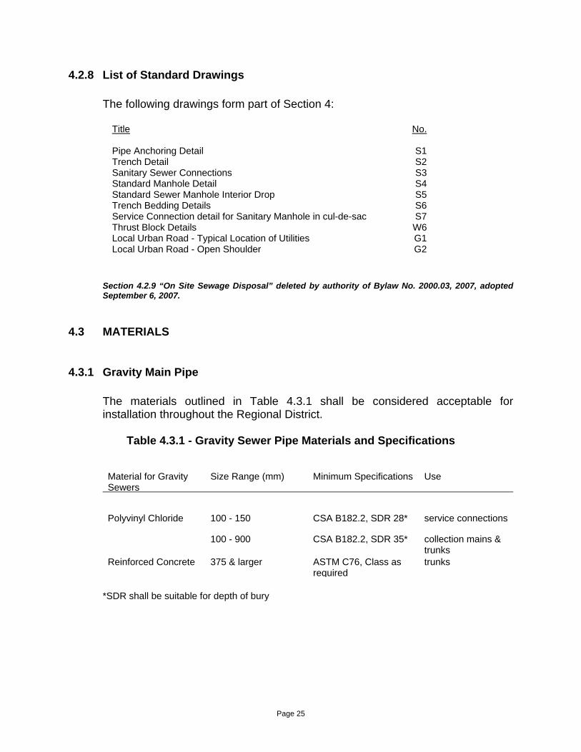
4.2.8 List of Standard Drawings
The following drawings form part of Section 4:
Title No.
Pipe Anchoring Detail S1 Trench Detail S2 Sanitary Sewer Connections S3 Standard Manhole Detail S4 Standard Sewer Manhole Interior Drop S5 Trench Bedding Details S6 Service Connection detail for Sanitary Manhole in cul-de-sac S7 Thrust Block Details W6 Local Urban Road - Typical Location of Utilities G1 Local Urban Road - Open Shoulder G2
Section 4.2.9 “On Site Sewage Disposal” deleted by authority of Bylaw No. 2000.03, 2007, adopted September 6, 2007.
4.3 MATERIALS
4.3.1 Gravity Main Pipe
The materials outlined in Table 4.3.1 shall be considered acceptable for installation throughout the Regional District.
Table 4.3.1 - Gravity Sewer Pipe Materials and Specifications
Material for Gravity Sewers
Size Range (mm) Minimum Specifications Use
Polyvinyl Chloride 100 - 150 CSA B182.2, SDR 28* service connections
100 - 900 CSA B182.2, SDR 35* collection mains & trunks
Reinforced Concrete 375 & larger ASTM C76, Class as required
trunks
*SDR shall be suitable for depth of bury
Page 25

4.3.2 Force Main Pipe
The materials outlined in Table 4.3.2 shall be considered acceptable for installation throughout the Regional District.
Table 4.3.2 - Force Main Sewer Pipe Materials and Specifications
Material for Forcemains
Size Range (mm)
Minimum Specifications
Use
Polyvinyl Chloride
100 & Larger AWWA C900 minor forcemains
Polyethylene 100 & Larger ASTM PE 2036 Series 160, CSA 137-1
minor forcemains
4.3.3 Pipe Joints
All gravity sewer pipe shall be jointed using rubber gaskets or gasket fittings and couplings. All sewer force main piping shall be jointed as specified for water main piping.
4.3.4 Manholes
All manholes shall be precast concrete, minimum 1,050 mm inside diameter and shall conform to A.S.T.M. C478. Manhole slabs shall be precast or cast in place on compacted material to Local Authority Standards using 20 MPA concrete and shall be 1,600 mm square.
Precast concrete lids shall be designed to withstand H-20 loading conditions. Cast iron frames and covers and manhole ladder rungs shall conform to Local Authority Standards.
4.3.5 Temporary Cleanouts
Temporary cleanout barrels, covers, base and lids shall conform to standards for manholes, or as accepted.
4.3.6 Service Connections
Polyvinyl chloride pipe and fittings shall be used for all service connections.
Page 26

4.3.7 Pipe Bedding
Pipe bedding classifications shall conform to Local Authority standards for Class "A" or, Class "B". Pipe bedding selection may vary for different materials installed and for different locations within the Regional District.
4.4 INSTALLATION
4.4.1 Excavation, Bedding, Backfill, Restoration
Excavation, bedding, backfill and restoration shall conform to the requirements of Section 3.4.1 of this Schedule.
4.4.2 Pipe Laying
Grading and aligning the pipe shall be effected with electronic aligning equipment unless otherwise approved by the Local Authority.
Pipe jointing and force main piping installation shall conform to the requirements of Section 3.4.2 of this Schedule. Vertical tolerance shall be 7 mm, plus or minus, for sanitary sewer gravity mains and 25 mm, plus or minus for sewer force mains.
4.4.3 Manholes, Cleanouts, and Appurtenances
Manholes, cleanouts and appurtenances shall be installed at the locations shown on the approved design drawings and in accordance with the Standard Drawings.
Manholes shall be set plumb and shall be constructed concurrently with the laying of the pipe. Manholes shall be constructed so as to be free from both ground water infiltration and exfiltration of sewage. All joints shall have a Butyl Mastic sealant and be mortared inside and out, including base, barrel, cover, bricking and frame.
Inlet and outlet elevations shall be as shown on the approved design drawings with tolerances as specified for pipe laying.
Page 27

4.4.4 Service Connections
Service connections shall be installed at the locations and depths shown on the approved drawings with the same tolerances as specified for pipelaying and as shown on the standard drawings.
4.4.5 Flushing and Testing
Prior to testing, all new mains are to be cleaned of debris by flushing by approved method and T.V. inspection and immediately afterwards capping the pipe ends in preparation for testing. This procedure will help to identify any misalignments on curved mains. All sanitary sewers shall be visually inspected to determine that they are straight.
Exfiltration tests shall be carried out on gravity sewers with either air or water as outlined below.
Testing for sanitary sewer forcemains shall conform to the testing criteria for watermains, but need not include disinfection.
Exfiltration Test for Gravity Sewers:
The allowable exfiltration (water method) shall be 10 litres per millimetre of pipe diameter per kilometre per day.
The allowable exfiltration (air method) shall be determined by filling the test section with air to a constant pressure of 25 Kpa and maintaining a pressure above 20 kPa for a minimum of 5 minutes. After the stabilization period, the air supply shall be cut off and the pressure allowed to drop to 20 kPa. Timing shall commence at 20 kPa and shall continue until the pressure reaches 15 kPa. The minimum acceptable time period shall be determined by the formula:
Minimum Time in min. = 0.040 x pipe dia. in millimetres
Where prevailing groundwater is above the sewer line being tested, the test pressure shall be increased 10 kPa for each metre of groundwater above the pipe.
An infiltration test may be required in areas of high groundwater, at the discretion of the Local Authority.
The Local Authority shall be notified 24 hours in advance of the leakage testing and may elect to witness the test. All test data and leakage calculations duly certified by a Professional Engineer are to be submitted to the Local Authority.
Page 28

5.0 STORM DRAINAGE
5.1 INTRODUCTION
Storm drainage facilities in highway right-of-ways fall under the jurisdiction of Ministry of Transportation which is responsible for maintenance thereof. All storm drainage facilities shall be designed and installed to Ministry of Transportation Standards and as stated in this Schedule or as accepted and generally conform to the British Columbia Environment "Urban Runoff Quality Control Guidelines for British Columbia", June 1992, document. In Schedule "B", the requirement for storm drainage with curb and gutter may be dispensed with at the discretion of the Ministry of Transportation and the Local Authority and replaced with a lower standard of drainage e.g. open drains. In this case, the proposed drainage system shall still be designed by a professional engineer and submitted for approval to the Ministry of Transportation.
5.2 DESIGN PARAMETERS
5.2.1 Design Methods and Flows
Design flows shall be based on the concept of the major and minor drainage systems and must attempt to maintain zero increase in peak flows over the pre-development flows. A drainage study to determine downstream affects may be required at the discretion of the Local Authority.
a) Minor System
The minor system consists of localized areas of development serviced by a localized piping or ditching system which discharges to the major component.
This system shall be designed to accommodate a ten year storm event. However, in doing so, it is mandatory that a comprehensive flood routing plan be developed which analyses the impact of surcharging flows on adjacent services and property.
b) Major System
The major component of the system consists of trunk mains which intercept flows from the minor system, natural drainage channels, overland flood routes and retention or detention facilities designed to reduce peaks. Overland flow through easements on private property is to be discouraged.
Page 29

This system shall be designed for a 100 year storm based on a recognized calculation method. It shall further conform to any stormwater management plan which may have been established by the Local Authority for each particular basin. Amendments to this program may only be permitted upon consultation with a detailed analysis by the Local Authority.
In areas of potential flood plain, the major system hydraulic grade line shall be identified and, to prevent flooding, minimum basement elevations shall be identified and established by covenant.
5.2.2 Flow Capacities for Storm Sewers and Open Channels:
Capacities for storm sewer mains and open channels shall be determined using Mannings' Formula:
Q = A X R 0.667 X S 0.5
N
Q = Design Flow in m3/sec A = Cross Sectional Area in m² R = Hydraulic Radius in m S = Slope of hydraulic grade line in m/m N = Roughness coefficient = 0.011 for P.V.C. pipe = 0.013 for Conc. pipe = 0.024 for unpaved corrugated steel pipe = 0.013 for concrete and asphalt line channels = 0.02 for gravel lined channels = 0.05 for natural and grassed channels
Page 30

5.2.3 Minimum Pipe Diameters, Velocities and Cover
The minimum diameter for storm sewer installations shall be as follows:
a) Storm Sewer Mains = 250 mm b) Catch Basin Leads = 200 mm c) Storm Sewer Service
Connections = 150 mm d) Driveway Culverts = 300 mm
Storm sewer mains shall be installed with a minimum clear cover above the pipe crown of 1.2 m.
Unless otherwise accepted, the minimum velocity for pipes flowing full or half full shall be 0.60 m/s.
Where grades for storm sewers exceed 30%, pipe anchors shall be installed.
Offsets for storm sewer mains shall be as shown on the standard drawings. Offsets may be changed where existing services require otherwise.
5.2.4 Manholes and Catch Basins
Manholes shall be installed at all vertical grade changes and on horizontal alignment changes where no curves are used. The maximum allowable spacing between storm sewer manholes shall be 120 m. Catch basins shall be placed at regular intervals along roadways, at intersections and at low points. The leads must be connected directly to a storm manhole. Spacing of catch basins shall be determined by the catchment area being serviced and the amount of runoff to be collected.
Page 31

5.2.5 Inlet and Outlet Structures
Inlet and outlet structures shall be designed to meet the requirements of each particular installation as per Standard Specifications for Highway Construction, however, the following guidelines shall be used as a basis for the minimum design requirements: a) Endwall
Used to retain embankment fill over pipe. End walls shall be designed with a minimum height of 300 mm above the pipe crown and a minimum width of 300 mm on either side of the pipe.
b) Wingwalls
Used to transition outlet and inlet to existing channel shape. Wingwall heights shall match the endwall height, however, sloping may be used depending on the installation requirements. Wingwall lengths shall be a minimum of 1.5 times the endwall width. Wingwalls shall be installed on a 30° or 45° angle from a perpendicular to the endwall.
c) Aprons or Spillways
Used to prevent erosion of channel bottoms at inlet and outlet structures and shall be located to meet the requirements of each particular installation.
d) Energy Dissipators
Used to reduce intake or discharge velocities. Energy dissipators shall be installed as required.
e) Trash Grate
To be bolted and removable with a normal maximum 150 mm spacing of vertical bars.
f) Sedimentation devices shall be installed on all outlets to a water course.
All designs for inlet and outlet structures shall be subject to acceptance by the Local Authority.
Page 32

5.2.6 Ditches
Where ditching has been approved either alone or in conjunction with an underground system, all ditching shall be constructed to Ministry of Transportation Standards and shall be hydro-seeded in the following manner:
a) A grass mixture in accordance with Ministry of Transportation Standards shall
be applied at a rate of 170 kg/ha.
b) Fertilizer (28-16-8) or approved formula at a rate of 170 kg/ha.
c) The hydro seeding solution should contain a mulch of wood cellulose fibre free of growth and germination inhibiting ingredients, and dyed green for visual metering during application. This mixture shall be applied at a rate of 2,250 kg/ha.
Energy dissipators may be required if deemed necessary to prevent erosion. Sediment control devices may be required.
Erosion protection may be required by Local Authority in fill area ditching or erodible soils.
5.2.7 Service Connection
The requirement for storm sewer connections to single family and duplex residential lots will be based on a geotechnical report on groundwater levels and requirements for foundation drains. Where required, they shall be installed to the property line at a minimum depth of 1.2 m.
Storm sewer connections for multi-family, commercial, institutional or industrial lots shall be a minimum 150 mm diameter and shall be installed up to property line at a minimum depth of 1.2 m. All services shall be marked with a 40 mm x 90 mm stake at the property line. The top 150 mm of the stake shall be painted green.
Storm sewer service connections do not require a cleanout at property line.
5.2.8 Trench Drains and Drywells
To promote interception of pollutants and reduction in storm flows, groundwater recharge systems are to be used where shown to be appropriate. The use of groundwater recharge systems will be based on a geotechnical evaluation of the native soils ability to absorb storm water runoff.
Page 33

5.2.9 Natural Watercourses
Natural watercourses shall be protected as directed by the Approving Officer.
5.2.10 List of Standard Drawings
Title No. Title No.
Standard Storm Drain Manhole Detail ST1 Trench Bedding Details S6 Catch Basin Detail ST2 Local Urban Road - Storm Drainage Drywell ST3 Typical Location of Utilities G1 Pipe Anchoring Detail S1 Local Urban Road - Open Shoulders G2 Trench Detail S2 Sanitary Sewer Connections S3 Manhole Detail S4
5.3 MATERIALS
5.3.1 Pipe
The materials outlined in Table 5.3.1 shall be considered acceptable for drainage installation throughout the District.
Table 5.3.1 - Acceptable Storm Drainage Pipe
Material Size Range (mm) Minimum Specification Use
Reinforced Concrete 300 & Larger ASTM C76, Class III Major trunks, culverts
Polyvinyl Chloride 150 CSA B182.2 SDR28 Service Connections only
200 - 900 CSA B182.2 SDR 35 Minor collection mains & service connections
200 - 600 (ultrarib)
CSA B182.4 Minor collection mains & service connections
Corrugated Steel Pipe 300 & Larger CAN 3 - G401-M81 Culverts only
HDPE Corrugated Pipe 300 & Larger ASTM D3350 ASTM F405
Culverts only
Consideration may be given to use of asphalt coated corrugated steel pipe for short major trunk mains.
Page 34

5.3.2 Pipe Joints
All pipe shall be jointed with rubber gaskets or gasketed fittings and couplings.
5.3.3 Manholes
Manhole barrels shall be precast concrete, 1,050 mm min. inside diameter and shall conform to ASTM C478 for all mains up to 380 mm in diameter. For mains 400 mm and larger in diameter cast in place structures combined with precast sections shall be utilized.
Manhole slabs shall be precast or cast in place on compacted material to Local Authority District Standards using 20 MPa concrete and shall be 1,600 mm square.
Pipe intersections in manholes shall utilize smooth hand formed concrete channels to maintain uniform flows. Minimum invert drops shall be as follows:
Straight Run = no drop required Deflections to 45° = 20 mm drop Deflections of 45° - 90° = 30 mm drop
5.3.4 Catch Basins
All catch basins shall be precast concrete 750 mm inside diameter. Precast barrels shall conform to ASTM C478.
Catch basin slabs shall be precast or cast in place on compacted material to Local Authority Standards.
Catch basins leads shall be 200 mm diameter and shall be installed a minimum of 460 mm from the upper side of the precast slab to allow for sediment collection. Catch basin leads shall be installed at a minimum 2% slope from the catch basin to the main.
5.3.5 Inlet and Outlet Structures
Endwalls and wingwalls shall be constructed using concrete filled sandbags, reinforced concrete or prefabricated sections. Aprons and spillways shall be constructed of reinforced concrete or rip-rap.
Page 35

5.3.6 Service Connections
Polyvinyl chloride pipe shall be used for all service connections.
5.4 INSTALLATION
5.4.1 Excavation, Bedding, Backfill, Restoration
Excavation, bedding, backfill and restoration shall conform to the requirements of Section 3.4.1. of this Schedule.
5.4.2 Pipe Laying
Storm sewer piping installation shall conform to the requirements of Section 4.4.2 of this Schedule. Vertical tolerances shall be 7 mm, plus or minus for storm sewer gravity mains.
5.4.3 Manholes, Catch Basin and Appurtenances
Manholes, catch basins and appurtenances shall be installed at the locations shown on the approved design drawings and in accordance with the Standard Drawings and Section 4.4.3 of this Schedule.
5.4.4 Service Connections
Service connections shall be installed at the locations and grades shown on the approved drawings with the same tolerances as specified for pipe laying.
5.4.5 Flushing and Testing
All storm sewers shall be flushed and lamped to determine that they are straight and free from silt, sand, earth or other debris. Exfiltration tests may be required with either air or water or video inspection as outlined in Section 4.4.5. at the discretion of the Local Authority.
An infiltration test may be required in areas of high groundwater at the discretion of the Local Authority.
Page 36

Page 37
5.4.6 Ditching
Ditches shall be graded to line, width and grade as shown on the approved drawings. Culverts, inlet and outlet structures, energy dissipators and other appurtenances shall be as shown on the approved drawings.

6.0 STREET LIGHTING
6.1 INTRODUCTION
All street lighting systems shall be designed by a Professional Engineer competent in lighting design, and in accordance with the International Illuminating Engineering Society and Local Authority standards where required by the Local Authority.
All materials, equipment and specifications shall be subject to approval of the Provincial Electrical Inspector prior to submission to the Local Authority for consideration.
The developer shall be responsible for obtaining all permits and payment of any fees required by the Provincial Electrical Inspector or the power utility company prior to start of construction.
Upon completion, the consulting engineer or contractor shall make provision to energize the system for inspection purposes and notify the Local Authority the system is ready to inspect. After completion of such inspection by the Local Authority and correction of remaining deficiencies, the Local Authority will then make application to energize the system when service is required.
Street lighting voltages shall be compatible with the local power authority service voltages.
Provision for future lighting of parks shall be made by installing ducts from the nearest street-light or junction to the park property line.
6.2 DESIGN PARAMETERS
6.2.1 Minimum Levels of Illumination
The levels of average horizontal illumination, in lux, for roadways and pedestrian walkways shall not be less than those outlined in Table 6.2.1.1.
Page 38

Table 6.2.1.1 - Average Horizontal Illumination (LUX)
Road Classification
Main Commercial Areas
Industrial & Intermediate
Residential Areas
Commercial Areas Arterial 22 15 *11 Collector 13 10 * 6 Local 10 6 4 Pedestrian Walkways 6 6 4
* Average horizontal illumination shall apply only to arterial or collector roads abutting
residential properties. Arterial or collector roads traversing a residential area but not abutting residential properties shall be designed to meet industrial and intermediate commercial area standards.
Differentiation between areas shall be at the discretion of the Approving Officer.
The maximum uniformity ratio of horizontal illumination for roadways and pedestrian walkways using a maintenance factor of 0.90 shall be as outlined in Table 6.2.1.2.
Table 6.2.1.2 - Uniformity Ratios
Road Classification
Uniformity Average: Minimum
Arterial 3:1 Collector 4:1 Local 5:1 Pedestrian Walkways 5:1
6.2.2 Pole Locations
All pole locations are subject to Ministry of Transportation approval for which a permit is required.
For arterial and collector roadways, pole installations shall utilize a staggered arrangement on both sides of the roadways and where possible be located on lot lines, away from driveways and underground services. On local roadways, pole installations shall utilize a one-side arrangement along the sidewalk side, however a staggered arrangement may be considered provided private utility companies are satisfied that no conflicts exist.
Page 39

Illumination levels differ for different classifications of roadways and where these roads meet, a transition area shall be incorporated. These shall have a gradual increase in illumination level until the higher level is reached.
On curves the luminaire spacing shall be reduced to ensure uniformity of illumination. Where poles are situated on the inside of bends the spacing must be reduced to +55% of the spacing on straight sections. On the outside of bends the spacing must be reduced to +70% of the normal spacing. Reduction figures are general guidelines and uniformity levels should dictate the required spacing.
Consideration shall be given to the relative positions of luminaires and trees to ensure that a uniform light distribution is maintained.
6.2.3 Underground Ducting Locations
In general, conduit shall be placed on the light side of the roadway. However, where a staggered type lighting pattern is utilized, conduit shall be placed on both sides of the roadway.
6.2.4 Lamp Standards and Luminaires
The types of standards and luminaires for different road classifications shall be as per Table 6.2.4.
Table 6.2.4 - Standards and Luminaires
Road Classification Standard Type Height Luminaire Description
Arterial Davit Arm NAPCO #29180-110-000 9.14 m 150 watt high pressure
sodium,
Collector Davit Arm NAPCO #29180-110-000 7.62 m 150 watt high pressure
sodium
Local Davit Arm NAPCO #29180-110-000 as per Std. Dwg.
7.62 m 100 Watt high pressure sodium,
E-1 or accepted post top as per Std. Dwg. E-2
6.0 m
Page 40

6.2.5 List of Standard Drawings
The following drawings form part of Section 6:
Title No. Davit Street Lights E1 Post Top Street Lights E2 Local Urban Road - Typical Location of Utilities G1 Local Urban Road - Open Shoulders G2
6.3 MATERIALS
All materials shall be C.S.A. approved and conform to the following specifications:
6.3.1 Poles
Poles shall be one piece octagonal tapered, factory primed steel to A.S.T.M. Standard A153 (610 gms/m2 inside and outside) designed to withstand 160 km/h wind loading. All poles shall be painted prior to installation and touched up to cover damaged areas after erection. Street light poles and accessories shall be as detailed on the standard drawings. Breakaway bases may be required at the discretion of the Local Authority.
6.3.2 Pole Bases
Precast concrete trapezoidal bases shall be installed on all pole installations. Under certain situations cast in place bases may be considered.
6.3.3 Conduit
All conduit, couplings, adapters and bends for street lighting shall be rigid unplasticized polyvinyl chloride, 50mm diameter minimum, Canadian Electrical Code, with maximum 30% conduit fill, unless otherwise accepted. Installation shall be in strict accordance with the manufacturer's recommendations using C.S.A. certified cement. Steel conduit for power service shall be hot-dipped galvanized malleable iron.
6.3.4 Grounding
Page 41

Grounding of neutral wire to grounding rod at each pole and service kiosk and installation of a continuous ground conductor in the conduit system shall be provided in accordance with the Provincial Electrical Code, #8 size, colour coded green.
6.3.5 Conductors
All conductors shall be type RW 90 X-link or RWU 90 X-link stranded copper. Minimum conductor size shall be #12. Conductor minimum size for advance warning flashers shall be #12. High traffic heads shall be wired with cabtire.
6.3.6 Connectors
Connectors shall be solderless insulated connectors of the Marrette type, taped with black P.V.C. tape. Full compression lugs shall be used for connecting ground conductors to ground studs in hand-holes.
6.3.7 Luminaires
All luminaires shall be acrylic type II, III or IV with cut-off or semi-cut-off distributions, in accordance with Section 6.2.4.
Polycarbonate vandal resistant refractors are required.
6.3.8 Lamps
All lamps shall be 150 watts or 100 watt high pressure sodium as applicable, colour corrected, deluxe coated.
6.3.9 Conduit Bedding
Bedding for buried conduit shall be sand or crushed granular aggregate as specified for PVC water piping. Utility warning tape shall be installed above all buried conduit.
Page 42

6.3.10 Junction Boxes
Junction boxes shall be cast aluminum, P.V.C. or concrete. Cast aluminum boxes shall be used in sidewalks in commercial areas; concrete boxes may be used in all other areas.
6.3.11 Service Panels
Service panels shall be C.S.A. approved of the pole mounting or kiosk type.
6.3.12 Photo-Cell Units
Photo-cell units shall be cadmium sulphide type having externally adjustable sensitivity, thermal on and off delay type for 120 volt operation and an integrally contained control relay capable of switching at least 1000 volt-amperes. The unit shall be provided with a twist-lock base to match the receptacle provided in the luminaire and the action shall be such that in daylight the relay is energized, holding open its normally closed contacts. The unit shall have a built-in surge protector and a lightning arrester.
One photo-cell unit shall be installed for each 10 or less streetlights on a circuit.
Where pole mounting is required an outdoor receptacle with wall mounting bracket shall be provided.
6.3.13 Ground Rods
Ground rods shall be 19 mm diameter steel with hot forged point. Top ends shall be galvanized for a minimum distance of 250 mm for 1500 mm rods and 450 mm for 3 metre rods. Ground rods shall be full length copper clad.
6.3.14 Paint
Primer shall be factory applied and any marks touched up with an accepted primer prior to painting. Paint shall be "Tremclad Dark Blue", or accepted equal.
Page 43

6.4 INSTALLATION
6.4.1 Layout and Positioning
Poles, pole bases, conduit and appurtenances shall be accurately located in accordance with the accepted drawings. Conduit shall be installed parallel or perpendicular to the road centreline and routed so as to run in a direct line between adjacent poles or junction boxes.
6.4.2 Conduit Installation
Conduit shall be installed in accordance with the manufacturer's recommendations.
Empty conduits shall be provided with an insulated #12 AWG copper wire and capped immediately after installation of the pull wire.
6.4.3 Poles, Bases and Luminaires
Bases shall be set plumb and oriented such that one side of the bolt square layout is parallel to the road centreline.
Poles shall receive one coat of paint prior to erection. Poles shall be set plumb with no more than 6 shims per pole.
Luminaires shall be securely fastened to the poles, levelled and cleaned after pole erection. Paint on poles shall be touched up after erection. If paint is badly scarred during installation, a second coat of paint shall be applied.
6.4.4 Wiring and Equipment
Wiring and equipment installation shall conform to the B.C. Electrical Code and manufacturer's recommendations.
Page 44

Page 45
6.4.5 Inspection and Testing
Inspection and testing shall conform to the provisions of the B.C. Electrical Code and the provisions of Section 6.1 hereof.
6.4.6 Installation on Power Utility Poles
Where street lighting is to be installed on power utility poles, the installations shall conform to the lighting level requirements of this Schedule and to the materials and installation requirements of the utility owner.

7.0 NON-MUNICIPAL UTILITIES
7.1 INTRODUCTION
Non-municipal utilities include natural gas, power, telephone and cablevision services. All underground services must have Ministry of Transportation approval and are subject to the permit procedures of the relevant utility company.
7.2 NATURAL GAS
Natural gas services are not required as a condition of subdivision, however, where natural gas services are to be installed, natural gas main and service installations shall conform to the requirements of the utility owner and natural gas mains shall be installed on both sides of new or upgraded roadways and located in accordance with the standard drawings herein for local roads. Installation of natural gas services, where available, is to be encouraged.
7.3 POWER
Electrical power services are required in accordance with Section 6 of this Bylaw. Where underground or overhead power services are to be installed, the installations shall conform to the requirements of the utility owner. Underground and overhead installations shall be located in accordance with the standard drawings herein for local roads.
7.4 TELEPHONE AND CABLEVISION
Telephone and cablevision services are not required as a condition of subdivision, however, where service is available, installation is to be encouraged.
Where underground or overhead telephone and cablevision services are to be installed, the installations shall conform to the requirements of the respective utility owners and shall be located in accordance with the standard drawings herein for local roads.
Page 46

Page 47
8.0 STANDARD DRAWINGS
8.1 GENERAL NOTES
1. Where CSA, ASTM, AWWA or other non-Municipal Standard Specifications are referred to, the most recent edition at the date of commencement of construction will apply.
2. All castings shall be true to pattern and free from cracks, gas holes, flaws,
and excessive shrinkage. Surfaces of the castings shall be free from burnt on sand and shall be reasonably smooth. Runners, risers, fins, and other cast on pieces shall be removed. In other respects, the castings shall conform to whatever points may be specially agreed upon between the manufacturer and the Local Authority.
Frame material specification - Cast Iron ASTM A48 - Class 20
Grate and cover material specification - Ductile Iron ASTM A445 or cast steel grade 60 - 90 (Table 11 ASTM A 148)
3. "as approved" means as accepted for the specific application by the Local
Authority.
4. All valve boxes, manholes and catch basin covers or grates to be set 5 - 10 mm below finished paved asphalt road grade, and 25 mm below finished gravel surface grade.
5. Standard drawings are to represent the preferred methodology under
standard conditions and are to be used wherever practical. This does not rule out the development or use of other methods after appropriate approvals have been obtained from the Local Authority. Any special conditions or deviations from standard drawings must be submitted as design details and will, after approval, take precedence over the standard drawing. Therefore, any standard drawing developed for non-standard situation must specify on the drawing the specific use intended.
6. It is not the purpose of the standard drawings to detail a manufacturer's
product but only the conditions of the Local Authority's use of such product.
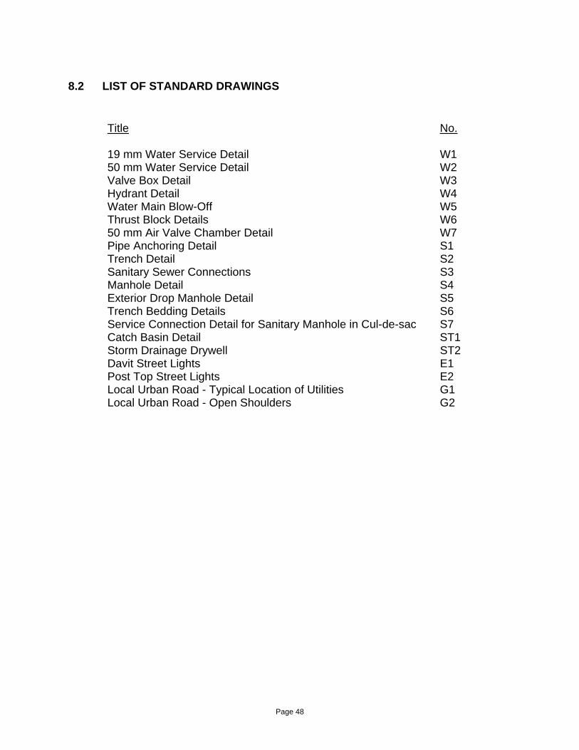
8.2 LIST OF STANDARD DRAWINGS
Title No.
19 mm Water Service Detail W1 50 mm Water Service Detail W2 Valve Box Detail W3 Hydrant Detail W4 Water Main Blow-Off W5 Thrust Block Details W6 50 mm Air Valve Chamber Detail W7 Pipe Anchoring Detail S1 Trench Detail S2 Sanitary Sewer Connections S3 Manhole Detail S4 Exterior Drop Manhole Detail S5 Trench Bedding Details S6 Service Connection Detail for Sanitary Manhole in Cul-de-sac S7 Catch Basin Detail ST1 Storm Drainage Drywell ST2 Davit Street Lights E1 Post Top Street Lights E2 Local Urban Road - Typical Location of Utilities G1 Local Urban Road - Open Shoulders G2
Page 48


SCHEDULE “B”

Schedule “B” deleted and replaced by authority of Subdivision Servicing Bylaw No. 2000.05, 2008, adopted by the Board January 8, 2009 Schedule “B” deleted and replaced by authority of Subdivision Servicing Bylaw No. 2000.06, 2008, adopted by the Board May 7, 2009 Schedule “B” deleted and replaced by authority of Subdivision Servicing Bylaw No. 2000.07, 2008, adopted by the Board May 7, 2009 Schedule “B” deleted and replaced by authority of Subdivision Servicing Bylaw No. 2000.08, 2009, adopted by the Board July 2, 2009
SCHEDULE B, TABLE B1 - LEVELS OF WORKS AND SERVICES
See Bylaw Section 2.0 for Applicability
Minimum Required Works and Services
Land Use
Parcel Area
Prov
en W
ater
Sup
ply
Com
mun
ity W
ater
Sup
ply
On-
Site
Sew
age
Dis
posa
l Sys
tem
Com
mun
ity S
ewer
Sys
tem
Stor
m S
ewer
with
C
urbs
& G
utte
r
Stre
et L
ight
ing
Ove
rhea
d W
iring
Und
ergr
ound
Wiri
ng
Side
wal
ks
Rural Single and Two Family Residential
1.4 Ha and Greater
4040 m2 - 1.39 Ha
2020 m2 - 4039 m2
505 m2 - 2019 m2
Multi-Family Residential N/A
Commercial, Tourist Commercial
Industrial, Institutional and Public Facilities
2020 m2 - Greater
505 m2 - 2019 m2
* = denotes required when available and/or as determined by the Local Authority.

SCHEDULE B, TABLE B2 - LEVELS OF WORKS AND SERVICES
Electoral Areas A, B, C, D, E, F, G and H
Minimum Required Works and Services
Land Use
Parcel Area
Pr
oven
Wat
er S
uppl
y
Com
mun
ity W
ater
Sup
ply
On-
Site
Sew
age
Dis
posa
l Sys
tem
Com
mun
ity S
ewer
Sys
tem
Stor
m S
ewer
with
C
urbs
& G
utte
r
Stre
et L
ight
ing
Ove
rhea
d W
iring
Und
ergr
ound
Wiri
ng
Side
wal
ks
Rural Single and Two Family Residential
1.4 Ha and Greater
1 Ha - 1.39 Ha
4040 m2 - 9999 m2
2020 m2- 4039 m2
505 m2 - 2019 m2
Multi-Family Residential N/A
Commercial, Tourist Commercial
Industrial, Institutional and Public Facilities
1 Ha and Greater
4040 m2 - 9999 m2
505 m2 - 4039 m2
505 m2 - 2019 m2
* = denotes required when available and/or as determined by the Local Authority.

Notes to Tables B1 and B2
1. Gas, cablevision and telephone services are not required as a condition of subdivision. However, where gas, cablevision or telephone services are to be provided, these shall comply with utility company requirements and be in accordance with this Bylaw.
2. Underground wiring and overhead wiring refers to the electricity service as well
as telephone and cable television when provided in a subdivision.


![C -I · 2020. 10. 23. · [leakge standard-awa awwa] i''2 awwa awwa awwa "-i awwa fawwa aluminium grating w1non- skid alum. plate [operating floor elevation 113400 1134.00 1134,00](https://static.fdocuments.net/doc/165x107/60b89c9699cbe6104d787a27/c-i-2020-10-23-leakge-standard-awa-awwa-i2-awwa-awwa-awwa-i-awwa.jpg)