
Regeneration Design
30
Regeneration Design
-
Upload
rindang-isnaniar-wisnu-aji -
Category
Documents
-
view
216 -
download
0
Transcript of Regeneration Design
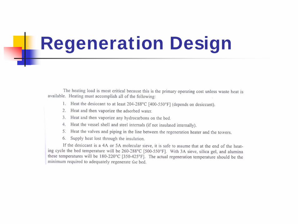
Regeneration Design
Regeneration Design
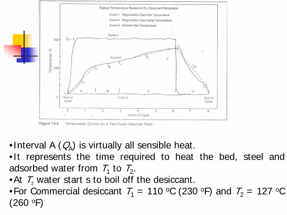
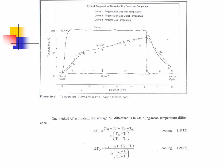
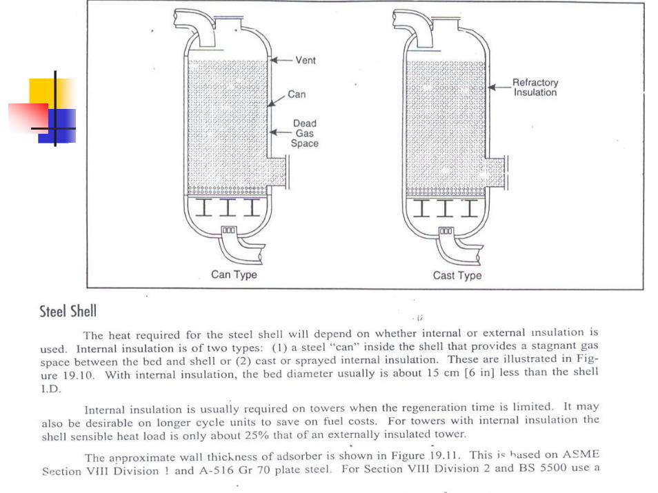
•Interval A (QA) is virtually all sensible heat.•It represents the time required to heat the bed, steel and adsorbed water from T1 to T2.•At T2 water start s to boil off the desiccant.•For Commercial desiccant T1 = 110 oC (230 oF) and T2 = 127 oC(260 oF)
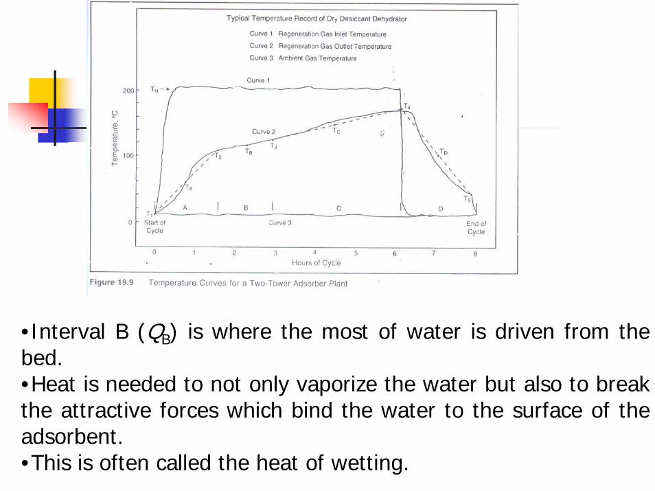
•Interval B (QB) is where the most of water is driven from the bed.•Heat is needed to not only vaporize the water but also to break the attractive forces which bind the water to the surface of theadsorbent.•This is often called the heat of wetting.
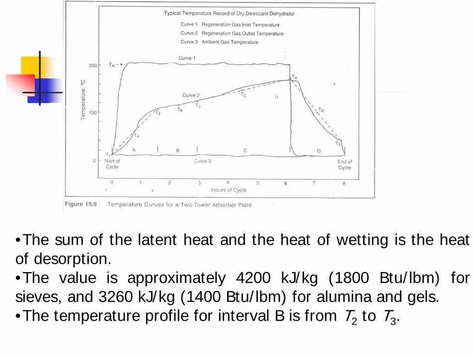
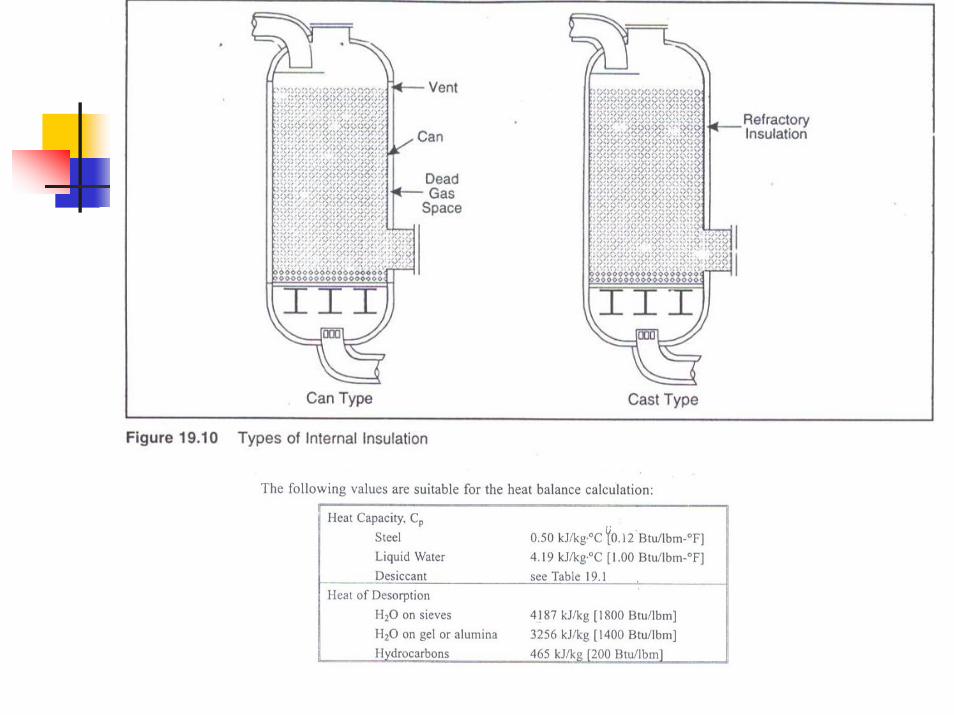
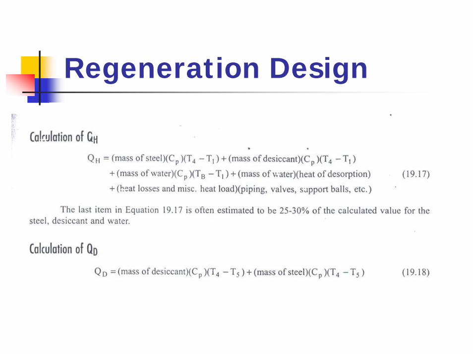
•The sum of the latent heat and the heat of wetting is the heat of desorption.•The value is approximately 4200 kJ/kg (1800 Btu/lbm) for sieves, and 3260 kJ/kg (1400 Btu/lbm) for alumina and gels.•The temperature profile for interval B is from T2 to T3.
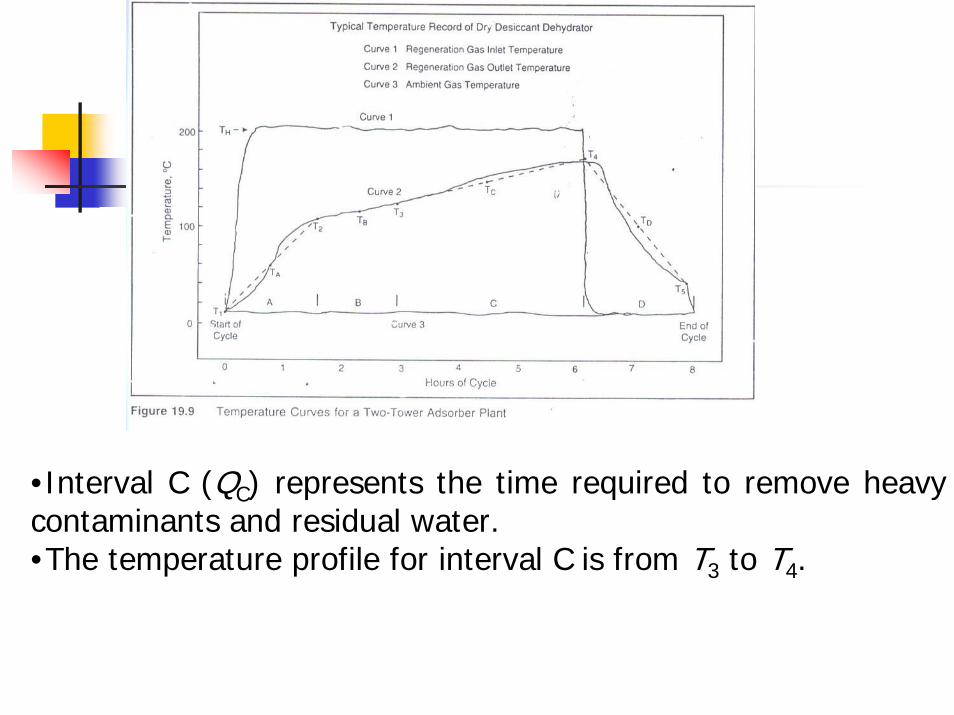
•Interval C (QC) represents the time required to remove heavy contaminants and residual water.•The temperature profile for interval C is from T3 to T4.
Regeneration Design
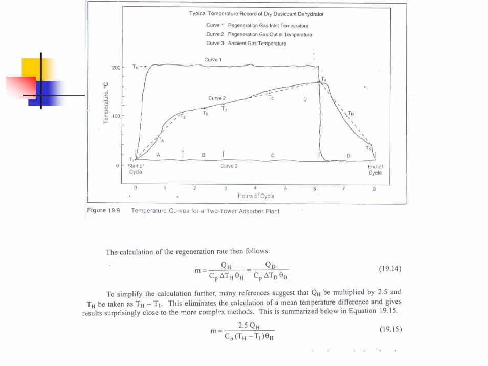
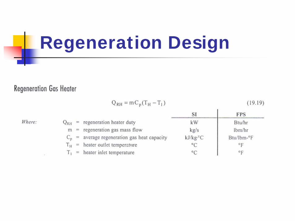
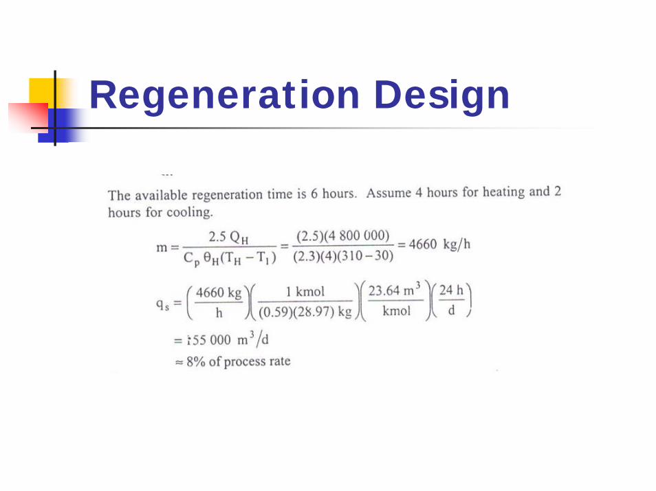
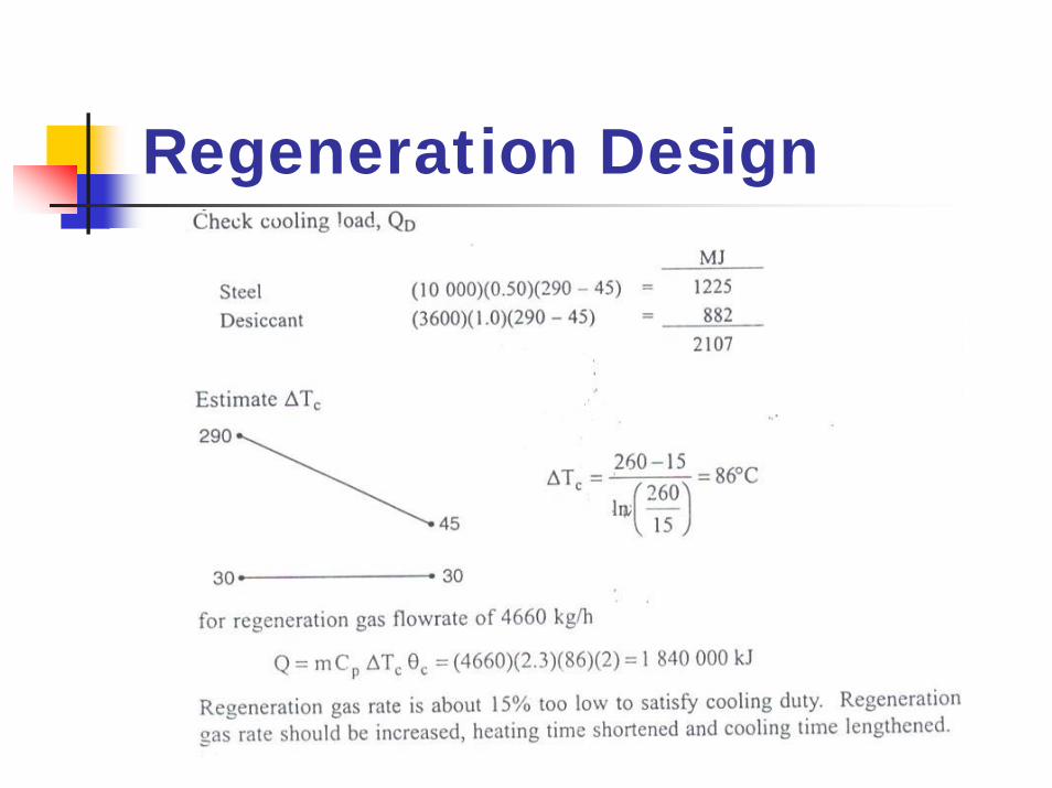
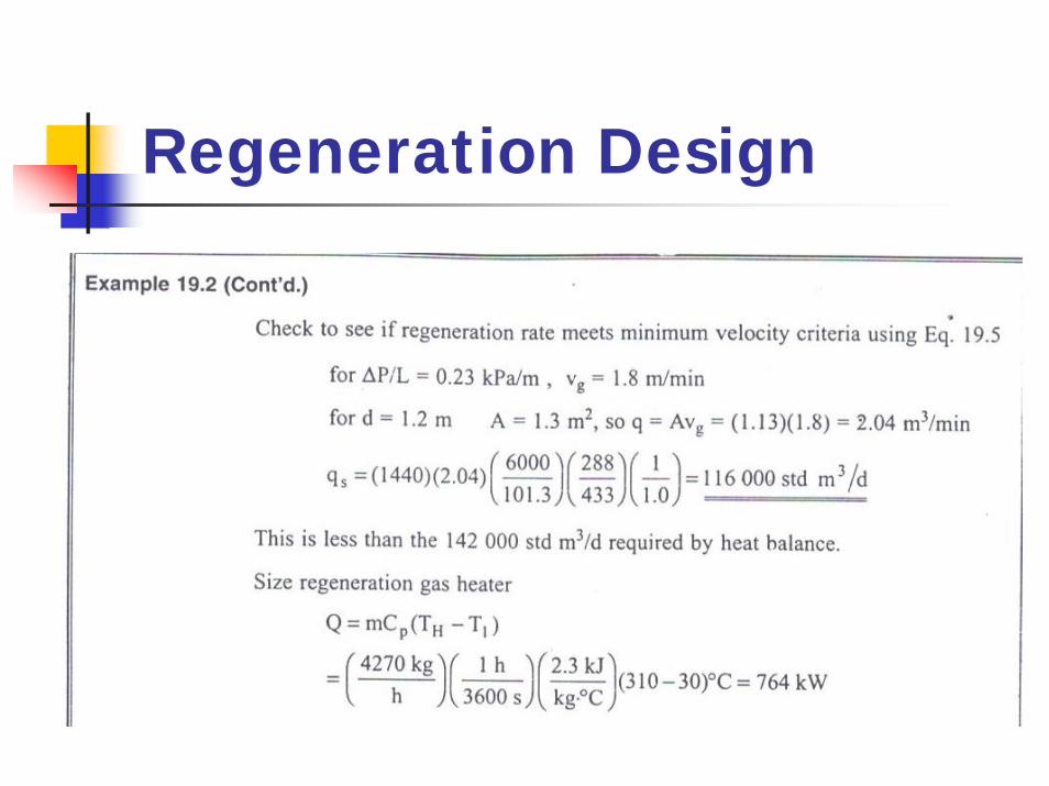
The regeneration gas flowrate is established by heat balance.The regeneration gas rate must mustbe adequate to deliver required heat input in the time available.It must also be sufficient to deliver the cooling in the time available
Regeneration Design
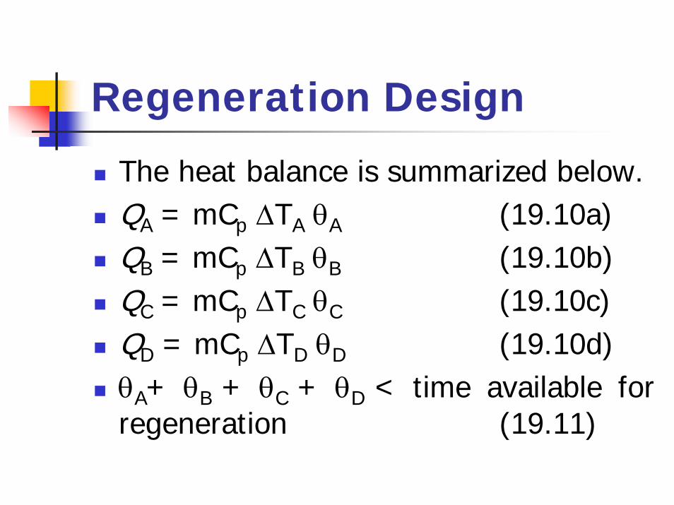
The heat balance is summarized below.QA = mCp ∆TA θA (19.10a)QB = mCp ∆TB θB (19.10b)QC = mCp ∆TC θC (19.10c)QD = mCp ∆TD θD (19.10d)θA+ θB + θC + θD < time available for regeneration (19.11)
Regeneration Design
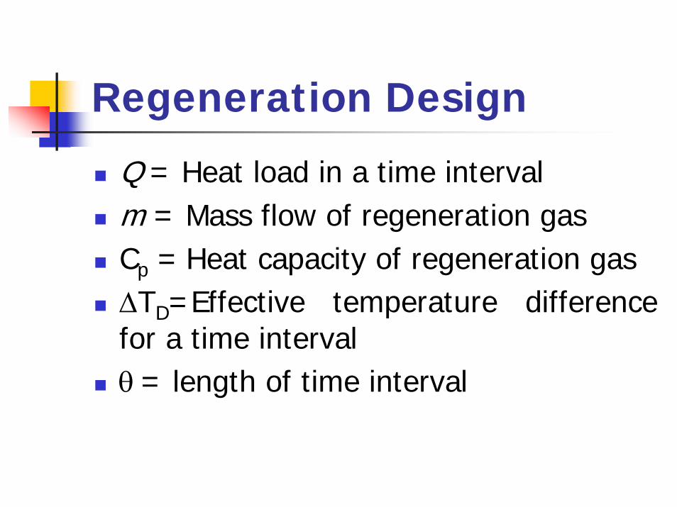
Q = Heat load in a time intervalm = Mass flow of regeneration gasCp = Heat capacity of regeneration gas∆TD=Effective temperature difference for a time intervalθ= length of time interval
Regeneration Design
For a two tower system, the time available for regeneration is equal to the adsorption time.For the three tower system, the time available is one-half the adsorption time.
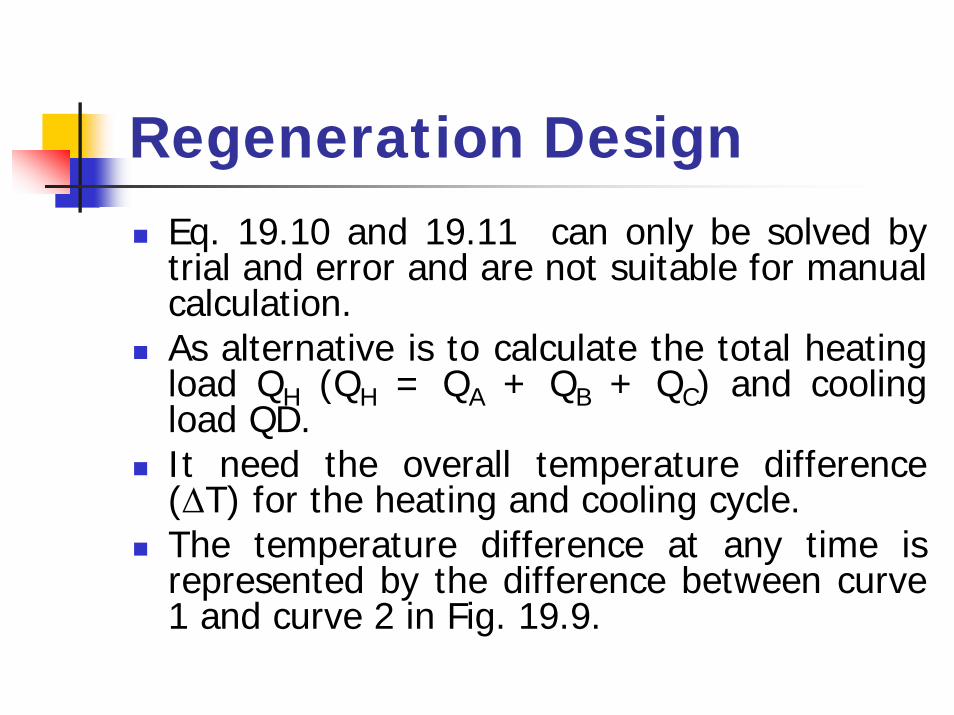
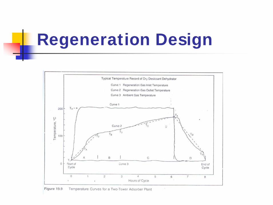
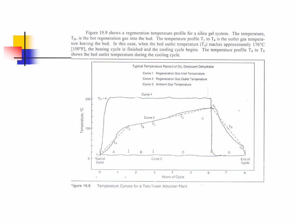
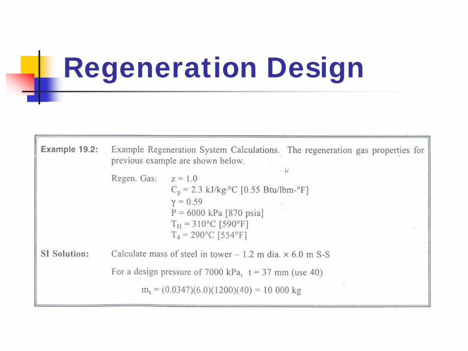
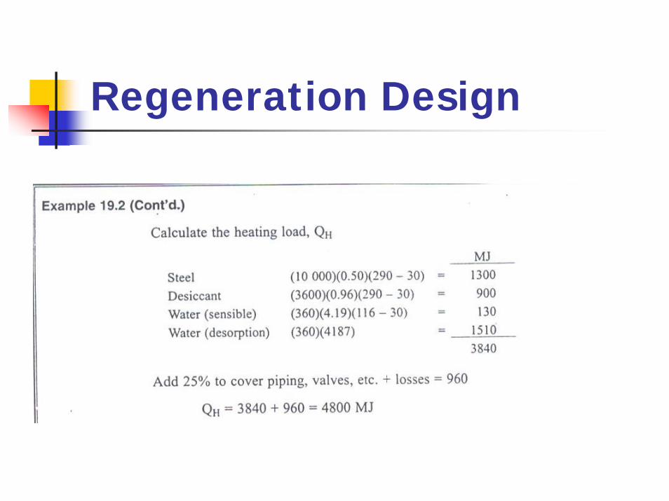
Regeneration DesignEq. 19.10 and 19.11 can only be solved by trial and error and are not suitable for manual calculation.As alternative is to calculate the total heating load QH (QH = QA + QB + QC) and cooling load QD.It need the overall temperature difference (∆T) for the heating and cooling cycle.The temperature difference at any time is represented by the difference between curve 1 and curve 2 in Fig. 19.9.
Regeneration Design
Regeneration Design
Regeneration Design
Regeneration Design
Regeneration Design
Regeneration Design
Regeneration Design
Regeneration Design
Regeneration Design

Regeneration DesignEq. 19.10 and 19.11 can only be solved by trial and error and are not suitable for manual calculation.As alternative is to calculate the total heating load QH (QH = QA + QB + QC) and cooling load QD.It need the overall temperature difference (∆T) for the heating and cooling cycle.The temperature difference at any time is represented by the difference between curve 1 and curve 2 in Fig. 19.9.