
Regal Vet-Mate Lift Gurney Owner’s ManualRegal Vet-Mate Lift Gurney Owner’s Manual Multiple...
40
Regal Vet-Mate Lift Gurney Owner’s Manual Multiple uses: gurney, lift table, etc. Adjusts to any height from 10.5 in. to 42 in. All stainless steel construction On-board battery & charger New Part Number: 12760-00-ITGLDK Former Part Number: 102840-00 SSCI Contact Information Contact SSCI Customer Service by mail, telephone or fax from 8:30am to 5:00pm, Central Time, Monday through Friday and closed holidays. Address: Suburban Surgical Co., Inc. 275 Twelfth street Wheeling, Illinois 60090 Telephone: Illinois-(847)537-9320, ext. 3518 Toll Free-(800)323-7366 Fax: (847)537-9061 Web: www.suburbansurgical.com E-mail: [email protected] Form No. TBD Revised 2/12/13
Transcript of Regal Vet-Mate Lift Gurney Owner’s ManualRegal Vet-Mate Lift Gurney Owner’s Manual Multiple...
Regal Vet-Mate Lift Gurney Owner’s Manual
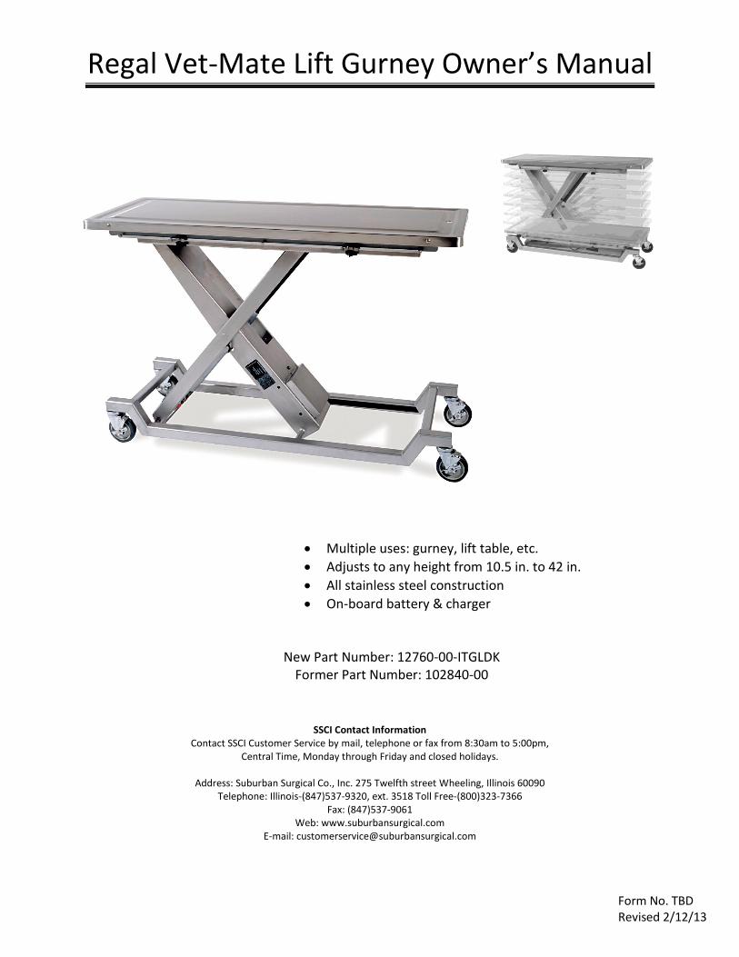
Multiple uses: gurney, lift table, etc.
Adjusts to any height from 10.5 in. to 42 in.
All stainless steel construction
On-board battery & charger
New Part Number: 12760-00-ITGLDK
Former Part Number: 102840-00
SSCI Contact Information Contact SSCI Customer Service by mail, telephone or fax from 8:30am to 5:00pm,
Central Time, Monday through Friday and closed holidays.
Address: Suburban Surgical Co., Inc. 275 Twelfth street Wheeling, Illinois 60090 Telephone: Illinois-(847)537-9320, ext. 3518 Toll Free-(800)323-7366
Fax: (847)537-9061 Web: www.suburbansurgical.com
E-mail: [email protected]
Form No. TBD Revised 2/12/13
P a g e | 1
www.SuburbanSurgical.com
Caution: Before selecting a chemical to employ in your facility, review label statements regarding use with metals (stainless steel). Always consult the chemical supplier if there are any doubts.
Care and Cleaning of Stainless Steel Introduction Stainless steel is steel alloyed with chromium to make it highly resistant to stain, rust, and corrosion. Note: This does NOT mean that stainless steel will never rust or corrode. Science has not yet developed a steel which is completely stainless or corrosion PROOF. The type of stainless steel and finish selected by SSCI for this product is the best available for the intended use.
Cleaning and Cleansers The basic rule of thumb is to use the mildest cleaning procedure that will do the job effectively. Always rinse thoroughly with clear water, and dry completely. Frequent cleaning will prolong the service life of stainless steel equipment and will help maintain a bright, pleasing appearance. Ordinary deposits of waste and fluids can usually be removed with soap and water. More stubborn deposits or tightly adhering debris may require harder scrubbing. They also may possibly require the use of commercial cleaning products acceptable for use on metal surfaces. When using any cleaning agent, rub in the direction of the polish lines or “grain” of the metal. For high luster finishes, clean soft cloths or pads should be used. If especially rough cleaning is necessary, use “stainless steel” wool, nylon or plastic scrubbers. Test these scrubbers in an inconspicuous area first to be sure they do not mark or scratch the stainless steel finish. Minor scale build-up and some hard water spotting may be removed by washing with some vinegar, followed by a neutralizing rinse with clear water. A thorough drying with a soft cloth should follow. For heavy deposits of scale, 5% oxalic acid (use warm), 5-15% sulfuric acid, or 5-10% phosphoric acid may be used. Always follow with a neutralizing rinse of clean water and a thorough drying. Never Power Wash the lift gurney, power washing it can damage the electrical components.
Deodorizing Agents, Disinfectants & Sanitizers The large selection of brands and combinations of chemicals available for deodorizing, disinfecting and sanitizing is staggering. Select one or more agents for use in your facility only after weighing in all the benefits claimed by each product. Often this choice is made without adequate consideration of the effects these agents may produce on equipment or furnishings. Avoid prolonged use of chlorides (such as chlorine bleach), bromides, iodides and thiocyanate on stainless steel surfaces as these chemicals will cause pitting, corrosion and metal discoloration. Allowing salty solutions to evaporate and dry on stainless steel may also contribute to corrosive
conditions. In summary, select chemical deodorizers, disinfectants and/or sanitizers only after weighing in all possible outcomes and known adverse effects.

P a g e | 2
www.SuburbanSurgical.com
Chapter 1 - General Information Introduction ............................................................................................................ 5 About this Manual................................................................................................... 5 Vet-Mate Lift Gurney Specifications........................................................................ 5 Information and Safety Notices .............................................................................. 6 Warranty .............................................................................................................................. 6 Safety.................................................................................................................................... 7 Crush Warning......................................................................................................... 7 Load Weight Limitations.......................................................................................... 7 Using the Wheel Brakes .......................................................................................... 7 Using the Restraint System...................................................................................... 7 Battery Charger ...................................................................................................... 7 Fluid Drain............................................................................................................... 7 Chapter 2 – Installation & Setup Unpacking and Installation...................................................................................... 8 Tools Required............................................................................................ 8 Procedure................................................................................................... 8 Chapter 3 - Operating Instructions Introduction ............................................................................................................ 9 Raising and Lowering the Gurney............................................................... 9 Moving the Gurney..................................................................................... 9 Using the Fluids Drain................................................................................. 10 Using the Restraint System......................................................................... 10 Checking the State of the Battery Charge…................................................ 10 Resetting the Fuse…................................................................................... 11 Replacing a Battery Charger Fuse…............................................................ 11 Removal …..................................................................................... 11 Inspection…................................................................................... 11 Installation …................................................................................. 11 Changing the Battery Charger Input Voltage…........................................... 12 Chapter 4 – Routine Maintenance Introduction…......................................................................................................... 13 Maintenance Schedule…......................................................................................... 13 Maintaining the Battery Charge…............................................................................ 14 Care of Wheel/Caster Assemblies …........................................................................ 14 Overview….................................................................................................. 14 Inspection…................................................................................................ 14 Equipment Frames and Fasteners…............................................... 14 Casters…........................................................................................ 14 Wheels …....................................................................................... 14 Brakes…......................................................................................... 15 Lubrication….............................................................................................. 15 Recommended Lubricants …......................................................... 15 Power Towed Operation….......................................................................... 15 Checking the Translation Tube Mounting Points …................................................. 15 Translation Tube Nut…............................................................................... 15 Rod End Retainer…..................................................................................... 15 Chapter 5 – Repairs and Replacements

P a g e | 3
www.SuburbanSurgical.com
Replacement Parts…................................................................................................ 16 General…................................................................................................................. 16 Parts Ordering Procedure ….................................................................................... 16 Procedures…............................................................................................................ 17 Battery ….................................................................................................... 17 Tools Required …........................................................................... 17 Removal …..................................................................................... 17 Installation …................................................................................. 17 Relay…........................................................................................................ 18 Overview…..................................................................................... 18 Tool Required….............................................................................. 18 Removal …..................................................................................... 18 Test the Relays …........................................................................... 18 Installation …................................................................................. 18 Battery Charger …....................................................................................... 19 Tools Required …........................................................................... 19 Removal …..................................................................................... 19 Installation …................................................................................. 19 Fuse (Battery Charger) …............................................................................ 20 Tools Required …........................................................................... 20 Removal …..................................................................................... 20 Inspection ….................................................................................. 21 Installation …................................................................................. 21 Power Cord for Battery…............................................................................ 21 Tools and Supplies Required …...................................................... 21 Removal …..................................................................................... 21 Installation …................................................................................. 22 Tie-down Assembly….................................................................................. 22 Overview…..................................................................................... 22 Tool Required….............................................................................. 22 Removal …..................................................................................... 22 Installation …................................................................................. 22 Gurney Top Assembly….............................................................................. 23 Tool Required….............................................................................. 23 Removal …..................................................................................... 23 Installation …................................................................................. 23 Raise/Lower Switch …................................................................................. 24 Overview…..................................................................................... 24 Tools Required …........................................................................... 24 Removal …..................................................................................... 24 Installation …................................................................................. 25 Electric Ball Drive Actuator…...................................................................... 26 Tools and Supplies Required …...................................................... 26 Removal …..................................................................................... 26 Adjusting the New Actuator …....................................................... 27 Installation …................................................................................. 27 Motor…....................................................................................................... 28 Overview…..................................................................................... 28

P a g e | 4
www.SuburbanSurgical.com
Tools and Supplies Required …...................................................... 28 Removal …..................................................................................... 28 Installation …................................................................................. 28 Motor Coupling …....................................................................................... 29 Overview…..................................................................................... 29 Tools and Supplies Required …...................................................... 29 Removal …..................................................................................... 29 Installation …................................................................................. 29 Brake …....................................................................................................... 30 Tools and Supplies Required …...................................................... 30 Removal …..................................................................................... 30 Installation …................................................................................. 30 Wheel/Caster Assembly…........................................................................... 31 Tools Required …........................................................................... 31 Removal …..................................................................................... 31 Installation …................................................................................. 31 Raising the Lift Gurney when the Battery is dead…................................... 32 Procedure…................................................................................... 32 Tools Required…............................................................................ 32 Chapter 6 – Troubleshooting General…................................................................................................................. 33 Problems…............................................................................................................... 33 Returning the Lift Gurney for Repairs ….................................................................. 33 RMA Numbers….......................................................................................... 33 Packing and Shipment….............................................................................. 33 Remedial Action………………………..………………………………………………………………………… 34 There is no electrical power at the gurney. …............................................ 34 The gurney will not raise or lower. …......................................................... 35 The gurney raises OK, but then slowly lowers by itself. ….......................... 35 The gurney makes noise while raising and lowering. …............................. 36 The gurney is hard to push…...................................................................... 36 The gurney keeps blowing fuses….............................................................. 36 The indicator light on the battery charger is dark…................................... 37 The battery should be charging but the yellow light is not on…................ 37 The battery should be charged but the green light does not come on…... 37 The red light on the battery charger is on. …............................................. 37
P a g e | 5
www.SuburbanSurgical.com
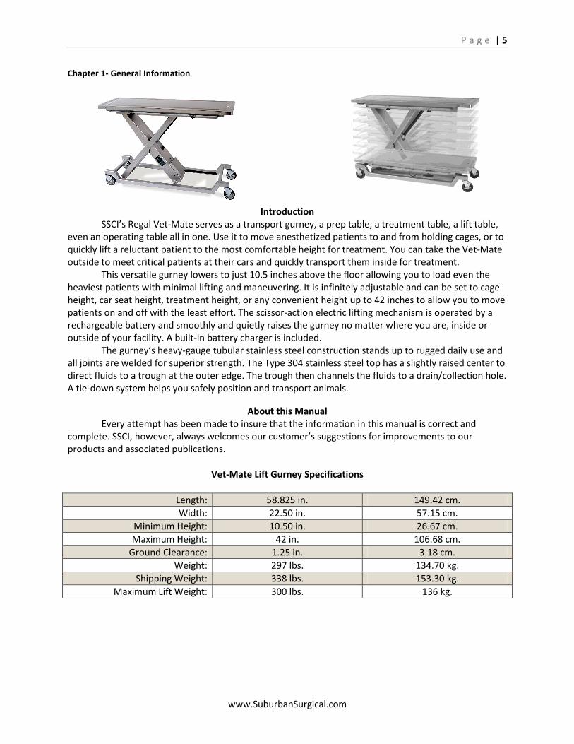
Chapter 1- General Information
Introduction SSCI’s Regal Vet-Mate serves as a transport gurney, a prep table, a treatment table, a lift table, even an operating table all in one. Use it to move anesthetized patients to and from holding cages, or to quickly lift a reluctant patient to the most comfortable height for treatment. You can take the Vet-Mate outside to meet critical patients at their cars and quickly transport them inside for treatment. This versatile gurney lowers to just 10.5 inches above the floor allowing you to load even the heaviest patients with minimal lifting and maneuvering. It is infinitely adjustable and can be set to cage height, car seat height, treatment height, or any convenient height up to 42 inches to allow you to move patients on and off with the least effort. The scissor-action electric lifting mechanism is operated by a rechargeable battery and smoothly and quietly raises the gurney no matter where you are, inside or outside of your facility. A built-in battery charger is included. The gurney’s heavy-gauge tubular stainless steel construction stands up to rugged daily use and all joints are welded for superior strength. The Type 304 stainless steel top has a slightly raised center to direct fluids to a trough at the outer edge. The trough then channels the fluids to a drain/collection hole. A tie-down system helps you safely position and transport animals.
About this Manual Every attempt has been made to insure that the information in this manual is correct and complete. SSCI, however, always welcomes our customer’s suggestions for improvements to our products and associated publications.
Vet-Mate Lift Gurney Specifications
Length: 58.825 in. 149.42 cm.
Width: 22.50 in. 57.15 cm.
Minimum Height: 10.50 in. 26.67 cm.
Maximum Height: 42 in. 106.68 cm.
Ground Clearance: 1.25 in. 3.18 cm.
Weight: 297 lbs. 134.70 kg.
Shipping Weight: 338 lbs. 153.30 kg.
Maximum Lift Weight: 300 lbs. 136 kg.
P a g e | 6
www.SuburbanSurgical.com
Warning: The electric ball drive actuator holds the gurney in its raised position. If the actuator is removed while the gurney is in the raised position, the gurney top will drop suddenly with considerable force. A high potential exists for injury to you or damage to the equipment.
Remove the green ground screw from the new switch. Note: Don’t lose the lockwasher.
Caution: Do not allow waste fluids to accumulate on the lower switch next to the hook. Fluids can damage the switch.
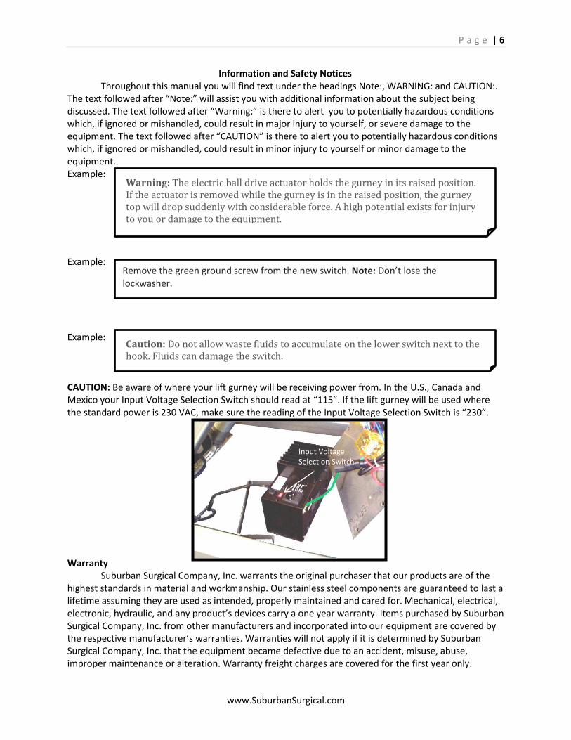
Information and Safety Notices Throughout this manual you will find text under the headings Note:, WARNING: and CAUTION:. The text followed after “Note:” will assist you with additional information about the subject being discussed. The text followed after “Warning:” is there to alert you to potentially hazardous conditions which, if ignored or mishandled, could result in major injury to yourself, or severe damage to the equipment. The text followed after “CAUTION” is there to alert you to potentially hazardous conditions which, if ignored or mishandled, could result in minor injury to yourself or minor damage to the equipment. Example: Example: Example: CAUTION: Be aware of where your lift gurney will be receiving power from. In the U.S., Canada and Mexico your Input Voltage Selection Switch should read at “115”. If the lift gurney will be used where the standard power is 230 VAC, make sure the reading of the Input Voltage Selection Switch is “230”. Warranty Suburban Surgical Company, Inc. warrants the original purchaser that our products are of the highest standards in material and workmanship. Our stainless steel components are guaranteed to last a lifetime assuming they are used as intended, properly maintained and cared for. Mechanical, electrical, electronic, hydraulic, and any product’s devices carry a one year warranty. Items purchased by Suburban Surgical Company, Inc. from other manufacturers and incorporated into our equipment are covered by the respective manufacturer’s warranties. Warranties will not apply if it is determined by Suburban Surgical Company, Inc. that the equipment became defective due to an accident, misuse, abuse, improper maintenance or alteration. Warranty freight charges are covered for the first year only.
Input Voltage Selection Switch
P a g e | 7
www.SuburbanSurgical.com
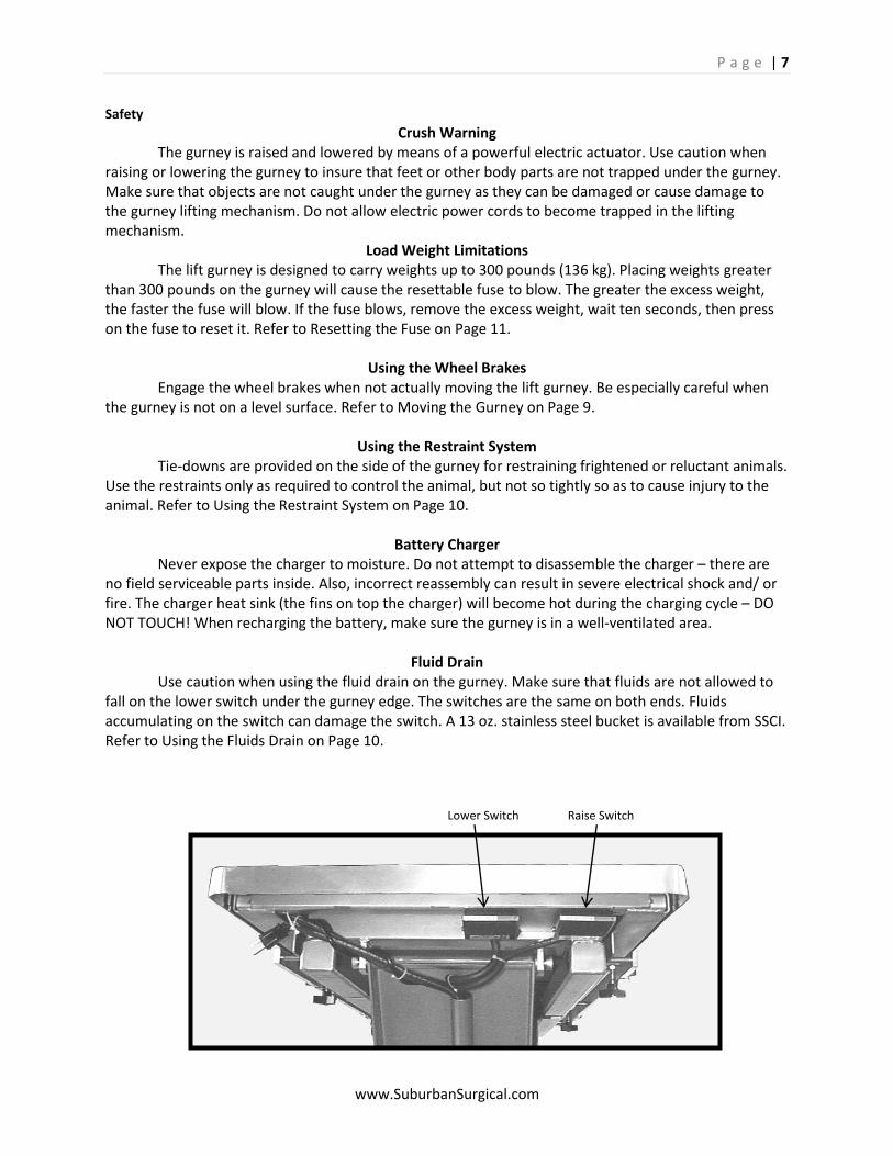
Lower Switch Raise Switch
Safety Crush Warning
The gurney is raised and lowered by means of a powerful electric actuator. Use caution when raising or lowering the gurney to insure that feet or other body parts are not trapped under the gurney. Make sure that objects are not caught under the gurney as they can be damaged or cause damage to the gurney lifting mechanism. Do not allow electric power cords to become trapped in the lifting mechanism.
Load Weight Limitations The lift gurney is designed to carry weights up to 300 pounds (136 kg). Placing weights greater than 300 pounds on the gurney will cause the resettable fuse to blow. The greater the excess weight, the faster the fuse will blow. If the fuse blows, remove the excess weight, wait ten seconds, then press on the fuse to reset it. Refer to Resetting the Fuse on Page 11.
Using the Wheel Brakes
Engage the wheel brakes when not actually moving the lift gurney. Be especially careful when the gurney is not on a level surface. Refer to Moving the Gurney on Page 9.
Using the Restraint System Tie-downs are provided on the side of the gurney for restraining frightened or reluctant animals. Use the restraints only as required to control the animal, but not so tightly so as to cause injury to the animal. Refer to Using the Restraint System on Page 10.
Battery Charger Never expose the charger to moisture. Do not attempt to disassemble the charger – there are no field serviceable parts inside. Also, incorrect reassembly can result in severe electrical shock and/ or fire. The charger heat sink (the fins on top the charger) will become hot during the charging cycle – DO NOT TOUCH! When recharging the battery, make sure the gurney is in a well-ventilated area.
Fluid Drain Use caution when using the fluid drain on the gurney. Make sure that fluids are not allowed to fall on the lower switch under the gurney edge. The switches are the same on both ends. Fluids accumulating on the switch can damage the switch. A 13 oz. stainless steel bucket is available from SSCI. Refer to Using the Fluids Drain on Page 10.
P a g e | 8
www.SuburbanSurgical.com
Caution: Unpacking the Vet-Mate Lift Gurney is not difficult. The gurney is heavy, however, and we recommend that unpacking be done by at least two people. Follow the instructions carefully to prevent injury to yourself or damage to the gurney.
Chapter 2- Installation & Set up
Unpacking and Installation Tools Required: ·Utility Knife, ·Phillips Screwdriver, ·Flat-blade screwdriver
Procedure
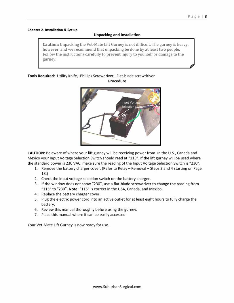
CAUTION: Be aware of where your lift gurney will be receiving power from. In the U.S., Canada and Mexico your Input Voltage Selection Switch should read at “115”. If the lift gurney will be used where the standard power is 230 VAC, make sure the reading of the Input Voltage Selection Switch is “230”.
1. Remove the battery charger cover. (Refer to Relay – Removal – Steps 3 and 4 starting on Page 18.)
2. Check the input voltage selection switch on the battery charger. 3. If the window does not show “230”, use a flat-blade screwdriver to change the reading from
“115” to “230”. Note: “115” is correct in the USA, Canada, and Mexico. 4. Replace the battery charger cover. 5. Plug the electric power cord into an active outlet for at least eight hours to fully charge the
battery. 6. Review this manual thoroughly before using the gurney. 7. Place this manual where it can be easily accessed.
Your Vet-Mate Lift Gurney is now ready for use.
Input Voltage Selection Switch
P a g e | 9
www.SuburbanSurgical.com
Chapter 3- Operating Instructions
Introduction Operating the SSCI Regal Vet-Mate Lift Gurney is very simple. The following instructions cover:
Raising and lowering the gurney - Below
Moving the gurney - Below
Using the fluids drain - Page 10
Using the restraint system - Page 10
Checking the state of the battery charge - Page 10
Resetting the fuse - Page 11
Replacing a battery charger fuse - Page 11
Changing the battery charger input voltage - Page 12
Raising and Lowering the Gurney Two switches under each end of the gurney allow you to raise and lower the gurney. The switches at both ends are identical in design and use.
To raise the gurney, press the raise switch.
To lower the gurney, press the lower switch. Hold either switch down until the gurney reaches the desired height, then release the switch.
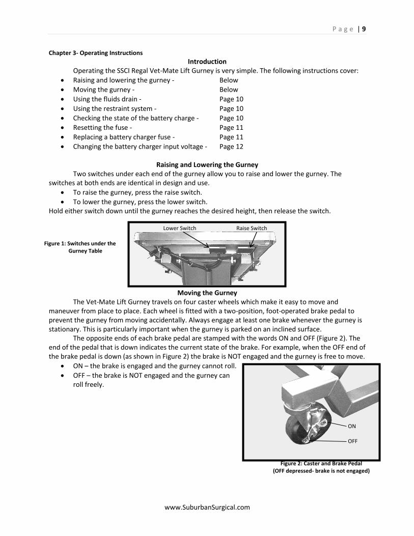
Moving the Gurney The Vet-Mate Lift Gurney travels on four caster wheels which make it easy to move and maneuver from place to place. Each wheel is fitted with a two-position, foot-operated brake pedal to prevent the gurney from moving accidentally. Always engage at least one brake whenever the gurney is stationary. This is particularly important when the gurney is parked on an inclined surface. The opposite ends of each brake pedal are stamped with the words ON and OFF (Figure 2). The end of the pedal that is down indicates the current state of the brake. For example, when the OFF end of the brake pedal is down (as shown in Figure 2) the brake is NOT engaged and the gurney is free to move.
ON – the brake is engaged and the gurney cannot roll.
OFF – the brake is NOT engaged and the gurney can roll freely.
Lower Switch Raise Switch
ON OFF
Figure 2: Caster and Brake Pedal
(OFF depressed- brake is not engaged)
Figure 1: Switches under the Gurney Table
P a g e | 10
www.SuburbanSurgical.com
Caution: Do not allow waste fluids to accumulate on the lower switch next to the hook. Fluids can damage the switch.
Using the Fluids Drain
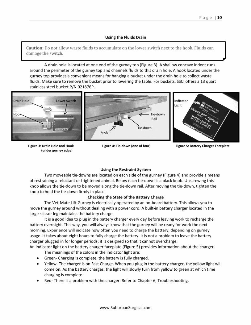
A drain hole is located at one end of the gurney top (Figure 3). A shallow concave indent runs around the perimeter of the gurney top and channels fluids to this drain hole. A hook located under the gurney top provides a convenient means for hanging a bucket under the drain hole to collect waste fluids. Make sure to remove the bucket prior to lowering the table. For buckets, SSCI offers a 13 quart stainless steel bucket P/N 021876P.
Using the Restraint System Two moveable tie-downs are located on each side of the gurney (Figure 4) and provide a means of restraining a reluctant or frightened animal. Below each tie-down is a black knob. Unscrewing this knob allows the tie-down to be moved along the tie-down rail. After moving the tie-down, tighten the knob to hold the tie-down firmly in place.
Checking the State of the Battery Charge The Vet-Mate Lift Gurney is electrically operated by an on-board battery. This allows you to move the gurney around without dealing with a power cord. A built-in battery charger located in the large scissor leg maintains the battery charge. It is a good idea to plug in the battery charger every day before leaving work to recharge the battery overnight. This way, you will always know that the gurney will be ready for work the next morning. Experience will indicate how often you need to charge the battery, depending on gurney usage. It takes about eight hours to fully charge the battery. It is not a problem to leave the battery charger plugged in for longer periods; it is designed so that it cannot overcharge. An indicator light on the battery charger faceplate (Figure 5) provides information about the charger. The meanings of the colors in the indicator light are:
Green- Charging is complete, the battery is fully charged.
Yellow- The charger is on Fast Charge. When you plug in the battery charger, the yellow light will come on. As the battery charges, the light will slowly turn from yellow to green at which time charging is complete.
Red- There is a problem with the charger. Refer to Chapter 6, Troubleshooting.
Drain Hole Lower Switch Indicator Light Hook Tie-down Rail Tie-down Knob
Figure 3: Drain Hole and Hook Figure 4: Tie-down (one of four) Figure 5: Battery Charger Faceplate (under gurney edge)
P a g e | 11
www.SuburbanSurgical.com
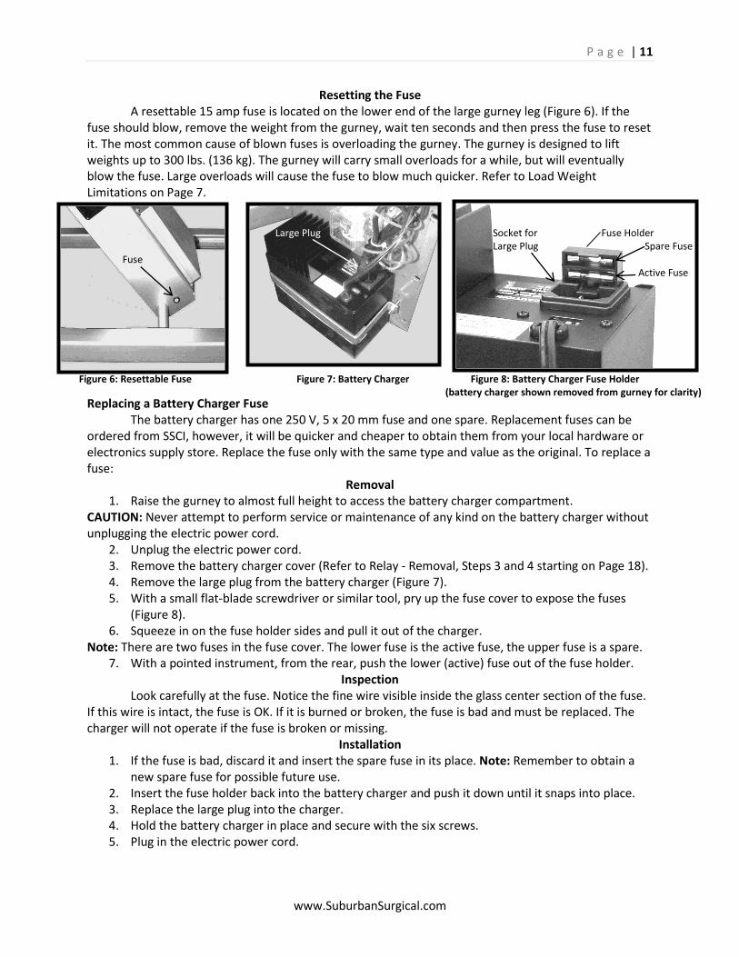
Resetting the Fuse A resettable 15 amp fuse is located on the lower end of the large gurney leg (Figure 6). If the fuse should blow, remove the weight from the gurney, wait ten seconds and then press the fuse to reset it. The most common cause of blown fuses is overloading the gurney. The gurney is designed to lift weights up to 300 lbs. (136 kg). The gurney will carry small overloads for a while, but will eventually blow the fuse. Large overloads will cause the fuse to blow much quicker. Refer to Load Weight Limitations on Page 7.
Replacing a Battery Charger Fuse The battery charger has one 250 V, 5 x 20 mm fuse and one spare. Replacement fuses can be ordered from SSCI, however, it will be quicker and cheaper to obtain them from your local hardware or electronics supply store. Replace the fuse only with the same type and value as the original. To replace a fuse:
Removal 1. Raise the gurney to almost full height to access the battery charger compartment.
CAUTION: Never attempt to perform service or maintenance of any kind on the battery charger without unplugging the electric power cord.
2. Unplug the electric power cord. 3. Remove the battery charger cover (Refer to Relay - Removal, Steps 3 and 4 starting on Page 18). 4. Remove the large plug from the battery charger (Figure 7). 5. With a small flat-blade screwdriver or similar tool, pry up the fuse cover to expose the fuses
(Figure 8). 6. Squeeze in on the fuse holder sides and pull it out of the charger.
Note: There are two fuses in the fuse cover. The lower fuse is the active fuse, the upper fuse is a spare. 7. With a pointed instrument, from the rear, push the lower (active) fuse out of the fuse holder.
Inspection Look carefully at the fuse. Notice the fine wire visible inside the glass center section of the fuse. If this wire is intact, the fuse is OK. If it is burned or broken, the fuse is bad and must be replaced. The charger will not operate if the fuse is broken or missing.
Installation 1. If the fuse is bad, discard it and insert the spare fuse in its place. Note: Remember to obtain a
new spare fuse for possible future use. 2. Insert the fuse holder back into the battery charger and push it down until it snaps into place. 3. Replace the large plug into the charger. 4. Hold the battery charger in place and secure with the six screws. 5. Plug in the electric power cord.
Large Plug Socket for Fuse Holder Large Plug Spare Fuse Fuse Active Fuse
Figure 6: Resettable Fuse Figure 7: Battery Charger Figure 8: Battery Charger Fuse Holder (battery charger shown removed from gurney for clarity)
P a g e | 12
www.SuburbanSurgical.com
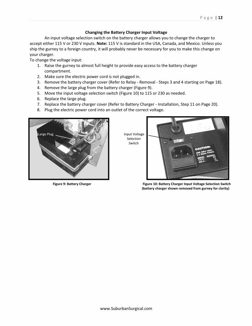
Changing the Battery Charger Input Voltage An input voltage selection switch on the battery charger allows you to change the charger to accept either 115 V or 230 V inputs. Note: 115 V is standard in the USA, Canada, and Mexico. Unless you ship the gurney to a foreign country, it will probably never be necessary for you to make this change on your charger. To change the voltage input:
1. Raise the gurney to almost full height to provide easy access to the battery charger compartment.
2. Make sure the electric power cord is not plugged in. 3. Remove the battery charger cover (Refer to Relay - Removal - Steps 3 and 4 starting on Page 18). 4. Remove the large plug from the battery charger (Figure 9). 5. Move the input voltage selection switch (Figure 10) to 115 or 230 as needed. 6. Replace the large plug. 7. Replace the battery charger cover (Refer to Battery Charger - Installation, Step 11 on Page 20). 8. Plug the electric power cord into an outlet of the correct voltage.
Large Plug Input Voltage Selection Switch Figure 9: Battery Charger Figure 10: Battery Charger Input Voltage Selection Switch (battery charger shown removed from gurney for clarity)
P a g e | 13
www.SuburbanSurgical.com
Chapter 4- Routine Maintenance
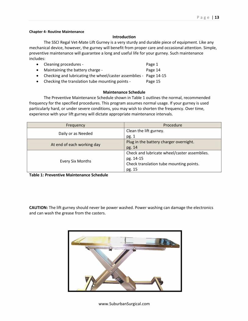
Introduction The SSCI Regal Vet-Mate Lift Gurney is a very sturdy and durable piece of equipment. Like any mechanical device, however, the gurney will benefit from proper care and occasional attention. Simple, preventive maintenance will guarantee a long and useful life for your gurney. Such maintenance includes:
Cleaning procedures - Page 1
Maintaining the battery charge - Page 14
Checking and lubricating the wheel/caster assemblies - Page 14-15
Checking the translation tube mounting points - Page 15
Maintenance Schedule The Preventive Maintenance Schedule shown in Table 1 outlines the normal, recommended frequency for the specified procedures. This program assumes normal usage. If your gurney is used particularly hard, or under severe conditions, you may wish to shorten the frequency. Over time, experience with your lift gurney will dictate appropriate maintenance intervals.
Frequency Procedure
Daily or as Needed Clean the lift gurney. pg. 1
At end of each working day Plug in the battery charger overnight. pg. 14
Every Six Months
Check and lubricate wheel/caster assemblies. pg. 14-15 Check translation tube mounting points. pg. 15
Table 1: Preventive Maintenance Schedule
CAUTION: The lift gurney should never be power washed. Power washing can damage the electronics and can wash the grease from the casters.
P a g e | 14
www.SuburbanSurgical.com
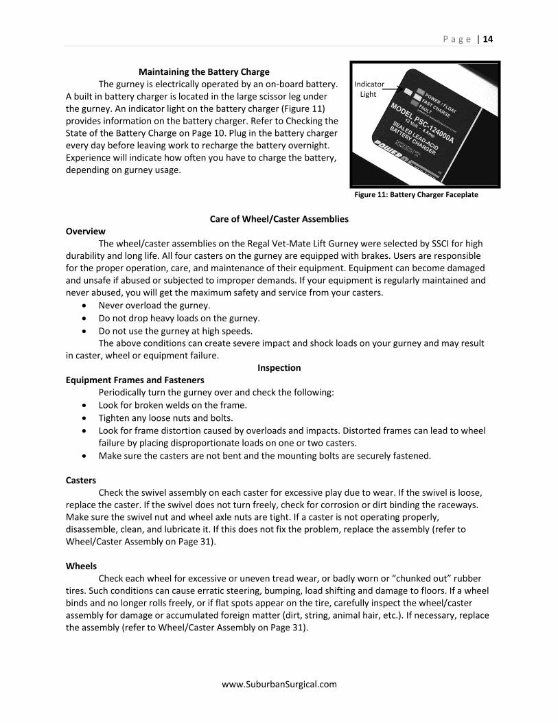
Maintaining the Battery Charge The gurney is electrically operated by an on-board battery. A built in battery charger is located in the large scissor leg under the gurney. An indicator light on the battery charger (Figure 11) provides information on the battery charger. Refer to Checking the State of the Battery Charge on Page 10. Plug in the battery charger every day before leaving work to recharge the battery overnight. Experience will indicate how often you have to charge the battery, depending on gurney usage.
Care of Wheel/Caster Assemblies Overview The wheel/caster assemblies on the Regal Vet-Mate Lift Gurney were selected by SSCI for high durability and long life. All four casters on the gurney are equipped with brakes. Users are responsible for the proper operation, care, and maintenance of their equipment. Equipment can become damaged and unsafe if abused or subjected to improper demands. If your equipment is regularly maintained and never abused, you will get the maximum safety and service from your casters.
Never overload the gurney.
Do not drop heavy loads on the gurney.
Do not use the gurney at high speeds. The above conditions can create severe impact and shock loads on your gurney and may result in caster, wheel or equipment failure.
Inspection Equipment Frames and Fasteners Periodically turn the gurney over and check the following:
Look for broken welds on the frame.
Tighten any loose nuts and bolts.
Look for frame distortion caused by overloads and impacts. Distorted frames can lead to wheel failure by placing disproportionate loads on one or two casters.
Make sure the casters are not bent and the mounting bolts are securely fastened. Casters Check the swivel assembly on each caster for excessive play due to wear. If the swivel is loose, replace the caster. If the swivel does not turn freely, check for corrosion or dirt binding the raceways. Make sure the swivel nut and wheel axle nuts are tight. If a caster is not operating properly, disassemble, clean, and lubricate it. If this does not fix the problem, replace the assembly (refer to Wheel/Caster Assembly on Page 31). Wheels Check each wheel for excessive or uneven tread wear, or badly worn or “chunked out” rubber tires. Such conditions can cause erratic steering, bumping, load shifting and damage to floors. If a wheel binds and no longer rolls freely, or if flat spots appear on the tire, carefully inspect the wheel/caster assembly for damage or accumulated foreign matter (dirt, string, animal hair, etc.). If necessary, replace the assembly (refer to Wheel/Caster Assembly on Page 31).
Indicator Light Figure 11: Battery Charger Faceplate
P a g e | 15
www.SuburbanSurgical.com
Brakes Check brakes for proper operation. Apply brakes one at a time and attempt to move the equipment to make sure that each brake is not slipping or loose. If brakes slip due to worn or damaged wheels, replace the wheels immediately and retest the brakes. If the brake mechanism itself is not operating properly, repair or replace it. Before returning the equipment to use, always retest the brakes.
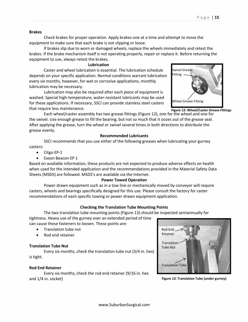
Lubrication Caster and wheel lubrication is essential. The lubrication schedule depends on your specific application. Normal conditions warrant lubrication every six months, however, for wet or corrosive applications, monthly lubrication may be necessary. Lubrication may also be required after each piece of equipment is washed. Special high-temperature, water-resistant lubricants may be used for these applications. If necessary, SSCI can provide stainless steel casters that require less maintenance. Each wheel/caster assembly has two grease fittings (Figure 12), one for the wheel and one for the swivel. Use enough grease to fill the bearing, but not so much that it oozes out of the grease seal. After applying the grease, turn the wheel or swivel several times in both directions to distribute the grease evenly.
Recommended Lubricants SSCI recommends that you use either of the following greases when lubricating your gurney casters:
Citgo EP-1
Exxon Beacon EP 1 Based on available information, these products are not expected to produce adverse effects on health when used for the intended application and the recommendations provided in the Material Safety Data Sheets (MSDS) are followed. MSDS’s are available via the Internet.
Power Towed Operation Power drawn equipment such as in a tow line or mechanically moved by conveyor will require casters, wheels and bearings specifically designed for this use. Please consult the factory for caster recommendations of each specific towing or power drawn equipment application.
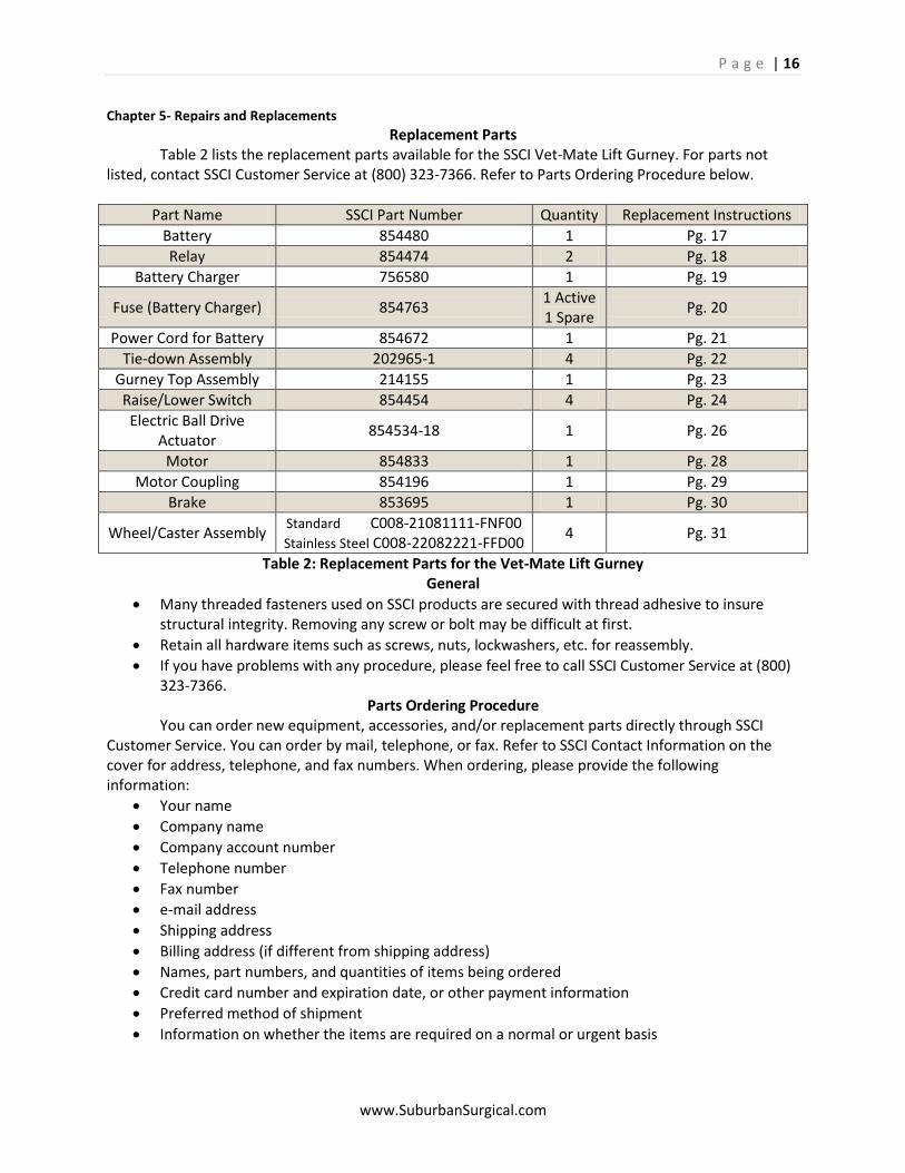
Checking the Translation Tube Mounting Points The two translation tube mounting points (Figure 13) should be inspected semiannually for tightness. Heavy use of the gurney over an extended period of time can cause these fasteners to loosen. These points are:
Translation tube nut
Rod end retainer Translation Tube Nut Every six months, check the translation tube nut (3/4 in. hex) is tight. Rod End Retainer Every six months, check the rod end retainer (9/16 in. hex and 1/4 in. socket)
Swivel Grease Fitting Wheel Grease Fitting Figure 12: Wheel/Caster Grease Fittings
Rod End Retainer Translation Tube Nut Translation Tube Figure 13: Translation Tube (under gurney)
P a g e | 16
www.SuburbanSurgical.com
Chapter 5- Repairs and Replacements
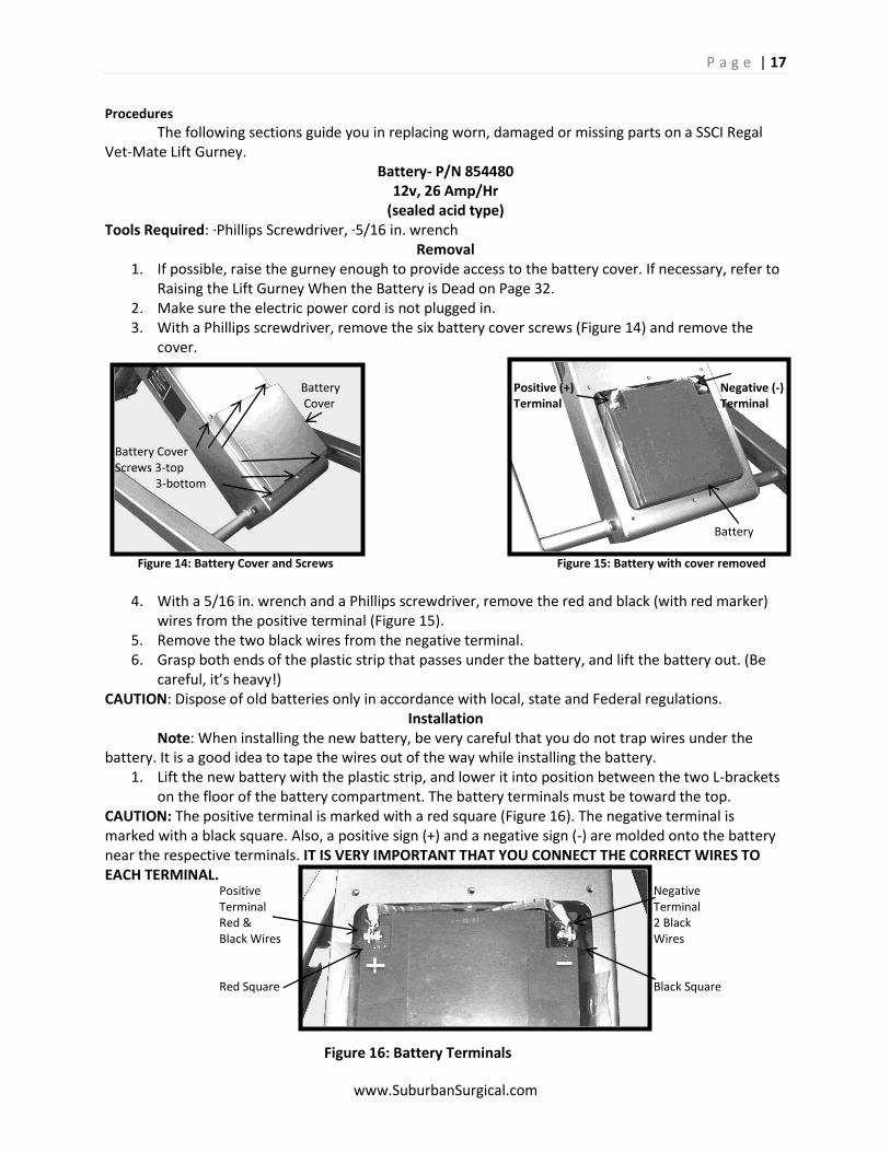
Replacement Parts Table 2 lists the replacement parts available for the SSCI Vet-Mate Lift Gurney. For parts not listed, contact SSCI Customer Service at (800) 323-7366. Refer to Parts Ordering Procedure below.
Part Name SSCI Part Number Quantity Replacement Instructions
Battery 854480 1 Pg. 17
Relay 854474 2 Pg. 18
Battery Charger 756580 1 Pg. 19
Fuse (Battery Charger) 854763 1 Active 1 Spare
Pg. 20
Power Cord for Battery 854672 1 Pg. 21
Tie-down Assembly 202965-1 4 Pg. 22
Gurney Top Assembly 214155 1 Pg. 23
Raise/Lower Switch 854454 4 Pg. 24
Electric Ball Drive Actuator
854534-18 1 Pg. 26
Motor 854833 1 Pg. 28
Motor Coupling 854196 1 Pg. 29
Brake 853695 1 Pg. 30
Wheel/Caster Assembly Standard C008-21081111-FNF00 Stainless Steel C008-22082221-FFD00
4 Pg. 31
Table 2: Replacement Parts for the Vet-Mate Lift Gurney General
Many threaded fasteners used on SSCI products are secured with thread adhesive to insure structural integrity. Removing any screw or bolt may be difficult at first.
Retain all hardware items such as screws, nuts, lockwashers, etc. for reassembly.
If you have problems with any procedure, please feel free to call SSCI Customer Service at (800) 323-7366.
Parts Ordering Procedure You can order new equipment, accessories, and/or replacement parts directly through SSCI Customer Service. You can order by mail, telephone, or fax. Refer to SSCI Contact Information on the cover for address, telephone, and fax numbers. When ordering, please provide the following information:
Your name
Company name
Company account number
Telephone number
Fax number
e-mail address
Shipping address
Billing address (if different from shipping address)
Names, part numbers, and quantities of items being ordered
Credit card number and expiration date, or other payment information
Preferred method of shipment
Information on whether the items are required on a normal or urgent basis
P a g e | 17
www.SuburbanSurgical.com
Procedures
The following sections guide you in replacing worn, damaged or missing parts on a SSCI Regal Vet-Mate Lift Gurney.
Battery- P/N 854480 12v, 26 Amp/Hr
(sealed acid type) Tools Required: ·Phillips Screwdriver, ·5/16 in. wrench
Removal 1. If possible, raise the gurney enough to provide access to the battery cover. If necessary, refer to
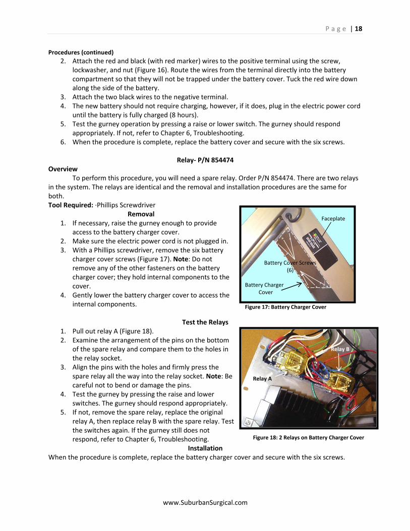
Raising the Lift Gurney When the Battery is Dead on Page 32. 2. Make sure the electric power cord is not plugged in. 3. With a Phillips screwdriver, remove the six battery cover screws (Figure 14) and remove the
cover.
4. With a 5/16 in. wrench and a Phillips screwdriver, remove the red and black (with red marker)
wires from the positive terminal (Figure 15). 5. Remove the two black wires from the negative terminal. 6. Grasp both ends of the plastic strip that passes under the battery, and lift the battery out. (Be
careful, it’s heavy!) CAUTION: Dispose of old batteries only in accordance with local, state and Federal regulations.
Installation Note: When installing the new battery, be very careful that you do not trap wires under the battery. It is a good idea to tape the wires out of the way while installing the battery.
1. Lift the new battery with the plastic strip, and lower it into position between the two L-brackets on the floor of the battery compartment. The battery terminals must be toward the top.
CAUTION: The positive terminal is marked with a red square (Figure 16). The negative terminal is marked with a black square. Also, a positive sign (+) and a negative sign (-) are molded onto the battery near the respective terminals. IT IS VERY IMPORTANT THAT YOU CONNECT THE CORRECT WIRES TO EACH TERMINAL.
Battery Positive (+) Negative (-) Cover Terminal Terminal Battery Cover Screws 3-top 3-bottom Battery Figure 14: Battery Cover and Screws Figure 15: Battery with cover removed
Positive Negative Terminal Terminal Red & 2 Black Black Wires Wires Red Square Black Square
Figure 16: Battery Terminals
P a g e | 18
www.SuburbanSurgical.com
Procedures (continued)
2. Attach the red and black (with red marker) wires to the positive terminal using the screw, lockwasher, and nut (Figure 16). Route the wires from the terminal directly into the battery compartment so that they will not be trapped under the battery cover. Tuck the red wire down along the side of the battery.
3. Attach the two black wires to the negative terminal. 4. The new battery should not require charging, however, if it does, plug in the electric power cord
until the battery is fully charged (8 hours). 5. Test the gurney operation by pressing a raise or lower switch. The gurney should respond
appropriately. If not, refer to Chapter 6, Troubleshooting. 6. When the procedure is complete, replace the battery cover and secure with the six screws.
Relay- P/N 854474
Overview To perform this procedure, you will need a spare relay. Order P/N 854474. There are two relays in the system. The relays are identical and the removal and installation procedures are the same for both. Tool Required: ·Phillips Screwdriver
Removal 1. If necessary, raise the gurney enough to provide
access to the battery charger cover. 2. Make sure the electric power cord is not plugged in. 3. With a Phillips screwdriver, remove the six battery
charger cover screws (Figure 17). Note: Do not remove any of the other fasteners on the battery charger cover; they hold internal components to the cover.
4. Gently lower the battery charger cover to access the internal components.
Test the Relays
1. Pull out relay A (Figure 18). 2. Examine the arrangement of the pins on the bottom
of the spare relay and compare them to the holes in the relay socket.
3. Align the pins with the holes and firmly press the spare relay all the way into the relay socket. Note: Be careful not to bend or damage the pins.
4. Test the gurney by pressing the raise and lower switches. The gurney should respond appropriately.
5. If not, remove the spare relay, replace the original relay A, then replace relay B with the spare relay. Test the switches again. If the gurney still does not respond, refer to Chapter 6, Troubleshooting.
Installation When the procedure is complete, replace the battery charger cover and secure with the six screws.
Faceplate Battery Cover Screws (6) Battery Charger Cover Figure 17: Battery Charger Cover
Relay B Relay A Figure 18: 2 Relays on Battery Charger Cover
P a g e | 19
www.SuburbanSurgical.com
Caution: Never attempt to perform service or maintenance of any kind on the battery charger without unplugging the electric power cord.
Procedures (continued)
Battery Charger- P/N 756580 Tools Required: ·Phillips Screwdriver, ·5/16 in. wrench, ·11/32 in. wrench
Removal 1. Raise the gurney to almost full height to provide easy access to the battery and battery charger
compartments. 2. Make sure the electric power cord is not plugged in. 3. Remove the battery cover and disconnect the wires at both terminals (Refer to Battery -
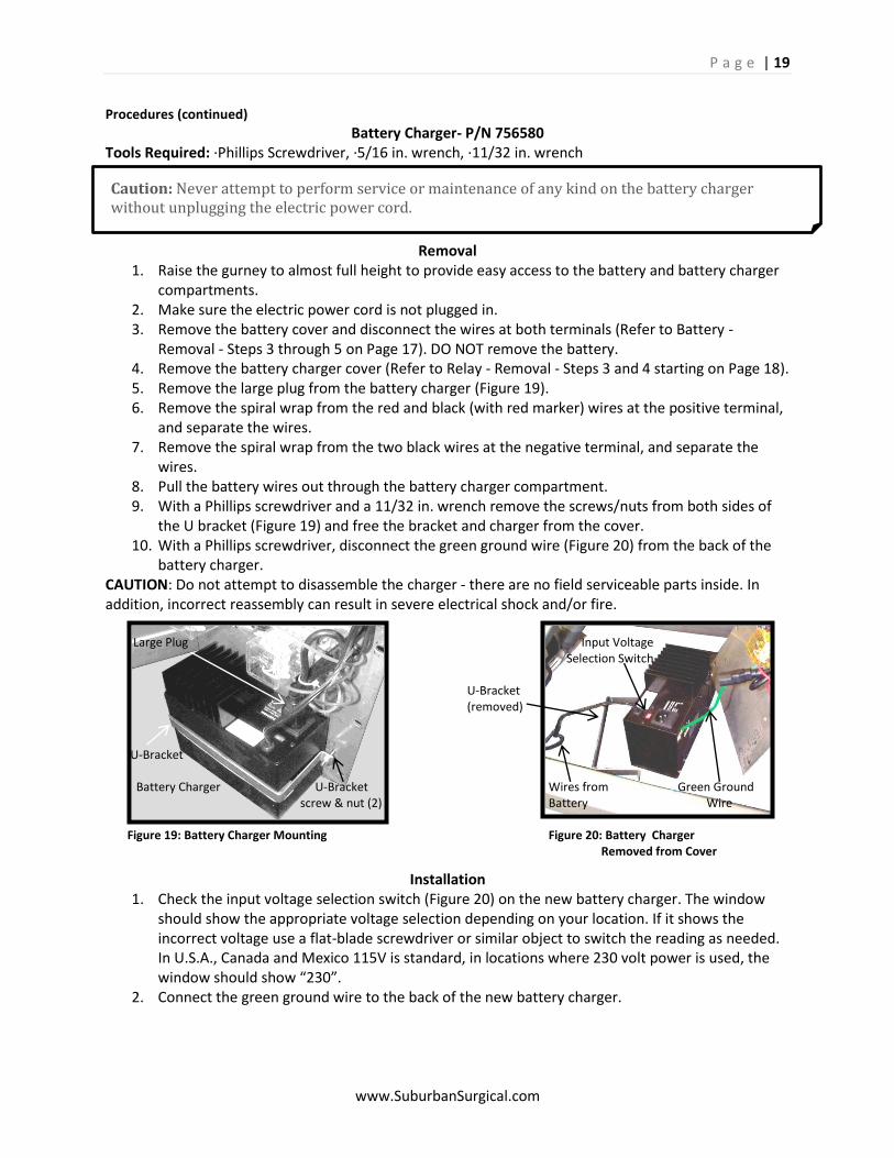
Removal - Steps 3 through 5 on Page 17). DO NOT remove the battery. 4. Remove the battery charger cover (Refer to Relay - Removal - Steps 3 and 4 starting on Page 18). 5. Remove the large plug from the battery charger (Figure 19). 6. Remove the spiral wrap from the red and black (with red marker) wires at the positive terminal,
and separate the wires. 7. Remove the spiral wrap from the two black wires at the negative terminal, and separate the
wires. 8. Pull the battery wires out through the battery charger compartment. 9. With a Phillips screwdriver and a 11/32 in. wrench remove the screws/nuts from both sides of
the U bracket (Figure 19) and free the bracket and charger from the cover. 10. With a Phillips screwdriver, disconnect the green ground wire (Figure 20) from the back of the
battery charger. CAUTION: Do not attempt to disassemble the charger - there are no field serviceable parts inside. In addition, incorrect reassembly can result in severe electrical shock and/or fire.
Installation 1. Check the input voltage selection switch (Figure 20) on the new battery charger. The window
should show the appropriate voltage selection depending on your location. If it shows the incorrect voltage use a flat-blade screwdriver or similar object to switch the reading as needed. In U.S.A., Canada and Mexico 115V is standard, in locations where 230 volt power is used, the window should show “230”.
2. Connect the green ground wire to the back of the new battery charger.
Large Plug Input Voltage Selection Switch U-Bracket (removed) U-Bracket Battery Charger U-Bracket Wires from Green Ground screw & nut (2) Battery Wire Figure 19: Battery Charger Mounting Figure 20: Battery Charger Removed from Cover
P a g e | 20
www.SuburbanSurgical.com
Caution: Never attempt to perform service or maintenance of any kind on the battery charger without unplugging the electric power cord.
Procedures (continued)
3. Mount the battery charger to the battery charger cover with the U-bracket and associated screws/nuts. Note: The bottom of the charger must be flush with the bottom edge of the cover. This permits the faceplate to show through the window in the scissor leg.
4. Route the small wires from the top of the battery charger (next to the voltage window) into the battery compartment then out over the top of the battery.
5. With one of the spiral wraps, bind the black wire with the red sleeve to the red battery wire. Note: Align the holes in the wire terminals to facilitate reconnection to the battery terminals.
6. With the remaining spiral wrap, bind the black wire from the battery charger to the black battery wire.
7. Attach the red and black (with red marker) wires to the positive terminal using the screw, lockwasher, and nut (Figure 16). Route the wires from the terminal directly into the battery compartment so that they will not be trapped under the battery cover. Tuck the red wire down along the side of the battery.
8. Attach the two black wires to the negative terminal. 9. Plug the large plug into the battery charger (Figure 19). 10. Test the gurney operation by pressing a raise or lower switch. The gurney should respond
appropriately. If the battery is dead, recharge the battery and repeat the test. If the gurney still does not respond, refer to Chapter 6, Troubleshooting.
11. If the gurney operates satisfactorily, hold the battery charger cover in place and secure with the six screws. Note: Do not trap or pinch the wires under the cover. Also, the battery charger faceplate must show through the opening in the side of the scissor leg (Figure 17).
12. Replace the battery cover and secure with the six screws.
Fuse (Battery Charger) -P/N 854763 250 V, 2Amp, 5 mm x 20 mm, Glass Tube, Fast-Acting
Tools Required: ·Phillips Screwdriver, ·Small flat-blade Screwdriver
Removal 1. Raise the gurney to almost full height to access the battery charger
compartment. 2. Unplug the electric power cord. 3. Remove the battery charger cover (Refer to Relay - Removal, Steps
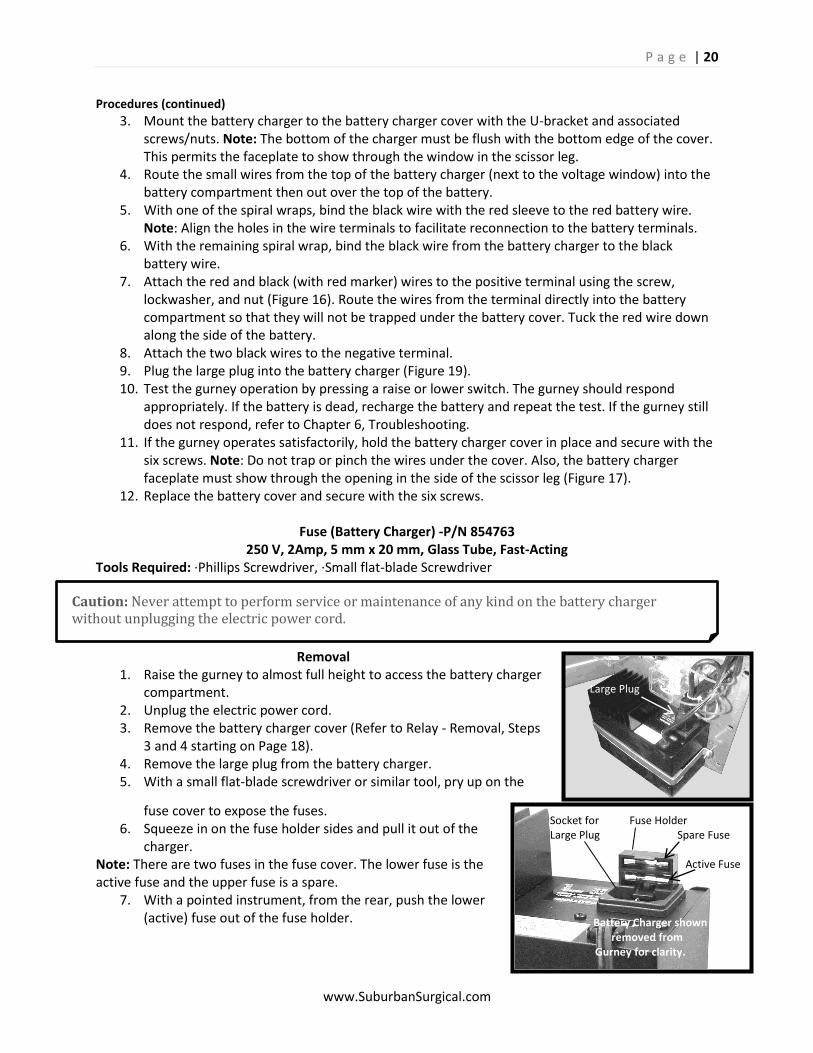
3 and 4 starting on Page 18). 4. Remove the large plug from the battery charger. 5. With a small flat-blade screwdriver or similar tool, pry up on the
fuse cover to expose the fuses. 6. Squeeze in on the fuse holder sides and pull it out of the
charger. Note: There are two fuses in the fuse cover. The lower fuse is the active fuse and the upper fuse is a spare.
7. With a pointed instrument, from the rear, push the lower (active) fuse out of the fuse holder.
Large Plug Socket for Fuse Holder Large Plug Spare Fuse Active Fuse Battery Charger shown removed from Gurney for clarity.
P a g e | 21
www.SuburbanSurgical.com
Procedures (continued)
Inspection Look carefully at the fuse. Notice the fine wire visible inside the glass center section of the fuse. If this wire is intact, the fuse is OK. If it is burned or broken, the fuse is bad and must be replaced. The charger will not operate if the fuse is broken or missing.
Installation 1. If the fuse is bad, discard it and insert the spare fuse in its place. Note: Remember to obtain a
new spare fuse for possible future use. 2. Insert the fuse holder back into the battery charger and push it all the way down until it snaps
into place. 3. Replace the large plug into the charger. 4. Replace the battery charger cover (Refer to Battery Charger - Installation, Step 11 on Page 20). 5. Plug in the electric power cord.
Power Cord for Battery- P/N 854672
Tools & Supplies Required: ·Phillips Screwdriver, ·Small flat-blade screwdriver, ·Knife or scissors (to cut cable ties), ·Cable ties, 8 in. long min. (4 to 6)
Removal 1. Raise the gurney enough to access the battery charger cover. If necessary, refer to Raising the
Lift Gurney when the Battery is Dead on Page 32. 2. Unplug the electric power cord. 3. With a Phillips screwdriver, remove the battery charger cover (Refer to Relay - Removal - Steps 3
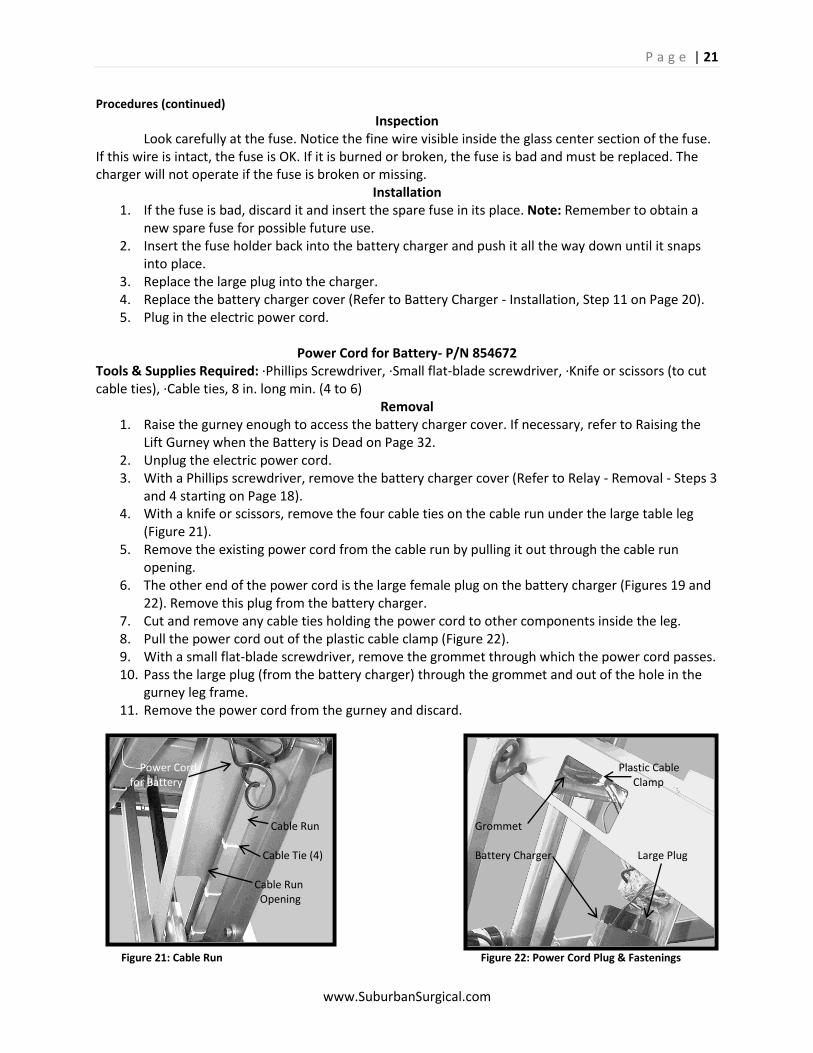
and 4 starting on Page 18). 4. With a knife or scissors, remove the four cable ties on the cable run under the large table leg
(Figure 21). 5. Remove the existing power cord from the cable run by pulling it out through the cable run
opening. 6. The other end of the power cord is the large female plug on the battery charger (Figures 19 and
22). Remove this plug from the battery charger. 7. Cut and remove any cable ties holding the power cord to other components inside the leg. 8. Pull the power cord out of the plastic cable clamp (Figure 22). 9. With a small flat-blade screwdriver, remove the grommet through which the power cord passes. 10. Pass the large plug (from the battery charger) through the grommet and out of the hole in the
gurney leg frame. 11. Remove the power cord from the gurney and discard.
Power Cord Plastic Cable for Battery Clamp Cable Run Grommet Cable Tie (4) Battery Charger Large Plug Cable Run Opening
Figure 21: Cable Run Figure 22: Power Cord Plug & Fastenings
P a g e | 22
www.SuburbanSurgical.com
Procedures (continued)
Installation 1. Pass the female plug (called “large plug” above) on the new power cord through the hole in the
leg frame. 2. Pass the female plug through the grommet removed in removal-Step 9. 3. Plug the female plug into the battery charger. 4. Place the power cord into the plastic cable clamp (Figure 22) and replace any cable ties removed
above. 5. Replace the grommet into the hole in the leg frame. 6. Pull as much of the power cord as possible out of the leg frame. 7. Place the power cord through the cable run opening and into the cable run. 8. Replace the four cable ties into the cable run. 9. Plug the power cord into an appropriate outlet. 10. Test the gurney operation and replace the battery cover. Refer to Battery Charger – Installation
– Steps 10 and 11 on Page 20.
Tie-down Assembly- P/N 202965-1 Overview The four tie-downs on the gurney are identical and the removal and installation procedures are the same for all of them. Tool Required: ·Phillips Screwdriver
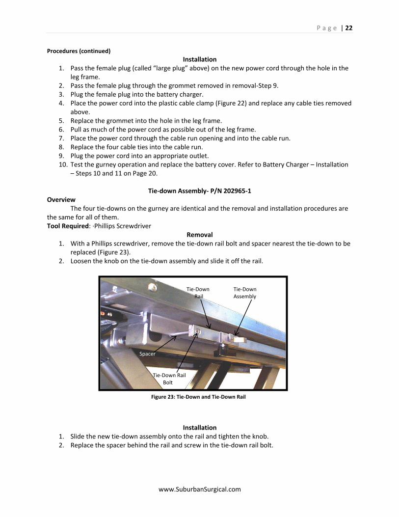
Removal 1. With a Phillips screwdriver, remove the tie-down rail bolt and spacer nearest the tie-down to be
replaced (Figure 23). 2. Loosen the knob on the tie-down assembly and slide it off the rail.
Installation 1. Slide the new tie-down assembly onto the rail and tighten the knob. 2. Replace the spacer behind the rail and screw in the tie-down rail bolt.
Tie-Down Tie-Down Rail Assembly Spacer Tie-Down Rail Bolt
Figure 23: Tie-Down and Tie-Down Rail
P a g e | 23
www.SuburbanSurgical.com
Caution: The gurney top is heavy. Lifting it on or off the unit should be done by at least two people.
Procedures (continued)
Gurney Top Assembly- P/N 214155 Tool Required: ·Phillips Screwdriver
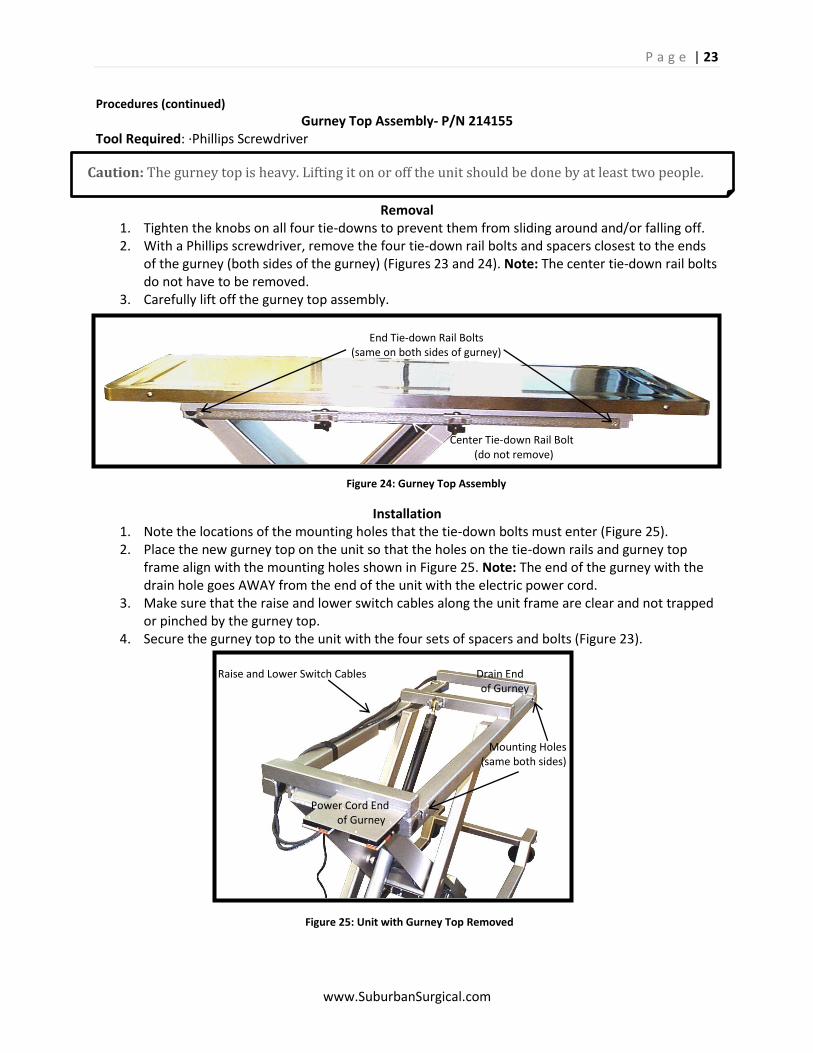
Removal 1. Tighten the knobs on all four tie-downs to prevent them from sliding around and/or falling off. 2. With a Phillips screwdriver, remove the four tie-down rail bolts and spacers closest to the ends
of the gurney (both sides of the gurney) (Figures 23 and 24). Note: The center tie-down rail bolts do not have to be removed.
3. Carefully lift off the gurney top assembly.
Installation 1. Note the locations of the mounting holes that the tie-down bolts must enter (Figure 25). 2. Place the new gurney top on the unit so that the holes on the tie-down rails and gurney top
frame align with the mounting holes shown in Figure 25. Note: The end of the gurney with the drain hole goes AWAY from the end of the unit with the electric power cord.
3. Make sure that the raise and lower switch cables along the unit frame are clear and not trapped or pinched by the gurney top.
4. Secure the gurney top to the unit with the four sets of spacers and bolts (Figure 23).
End Tie-down Rail Bolts (same on both sides of gurney)
Center Tie-down Rail Bolt (do not remove)
Figure 24: Gurney Top Assembly
Raise and Lower Switch Cables Drain End of Gurney Mounting Holes (same both sides) Power Cord End of Gurney
Figure 25: Unit with Gurney Top Removed
P a g e | 24
www.SuburbanSurgical.com
Caution: The gurney top must be removed to gain access to the switches. The gurney top is heavy. Lifting it on or off the unit should be done by at least two people.
Procedures (continued)
Raise/Lower Switch- P/N 854454 Overview All four raise/lower switches are identical and the removal and installation procedures for them are the same. Tools Required: ·Phillips Screwdriver, ·Small Phillips Screwdriver, ·Small flat-blade Screwdriver
Removal
1. Make sure the electric power cord is not plugged in. 2. Remove the gurney top. Refer to Gurney Top Assembly -
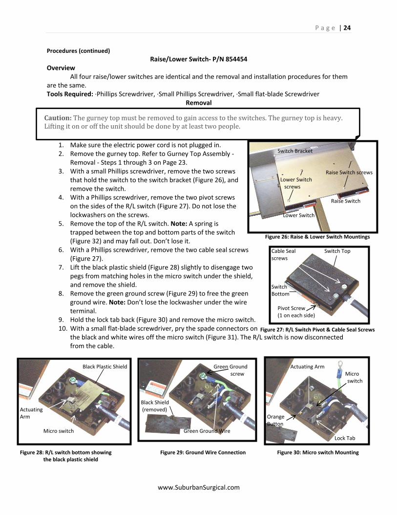
Removal - Steps 1 through 3 on Page 23. 3. With a small Phillips screwdriver, remove the two screws
that hold the switch to the switch bracket (Figure 26), and remove the switch.
4. With a Phillips screwdriver, remove the two pivot screws on the sides of the R/L switch (Figure 27). Do not lose the lockwashers on the screws.
5. Remove the top of the R/L switch. Note: A spring is trapped between the top and bottom parts of the switch (Figure 32) and may fall out. Don’t lose it.
6. With a Phillips screwdriver, remove the two cable seal screws (Figure 27).
7. Lift the black plastic shield (Figure 28) slightly to disengage two pegs from matching holes in the micro switch under the shield, and remove the shield.
8. Remove the green ground screw (Figure 29) to free the green ground wire. Note: Don’t lose the lockwasher under the wire terminal.
9. Hold the lock tab back (Figure 30) and remove the micro switch. 10. With a small flat-blade screwdriver, pry the spade connectors on
the black and white wires off the micro switch (Figure 31). The R/L switch is now disconnected from the cable.
Switch Bracket Raise Switch screws Lower Switch screws Raise Switch Lower Switch
Figure 26: Raise & Lower Switch Mountings Cable Seal Switch Top screws Switch Bottom Pivot Screw (1 on each side)
Figure 27: R/L Switch Pivot & Cable Seal Screws
Black Plastic Shield Green Ground Actuating Arm screw Micro switch Black Shield Actuating (removed) Arm Orange Button Micro switch Green Ground Wire Lock Tab Figure 28: R/L switch bottom showing Figure 29: Ground Wire Connection Figure 30: Micro switch Mounting the black plastic shield
P a g e | 25
www.SuburbanSurgical.com
Procedures (continued)
Installation 1. Open the new switch and remove the black plastic shield the same way as you did the old
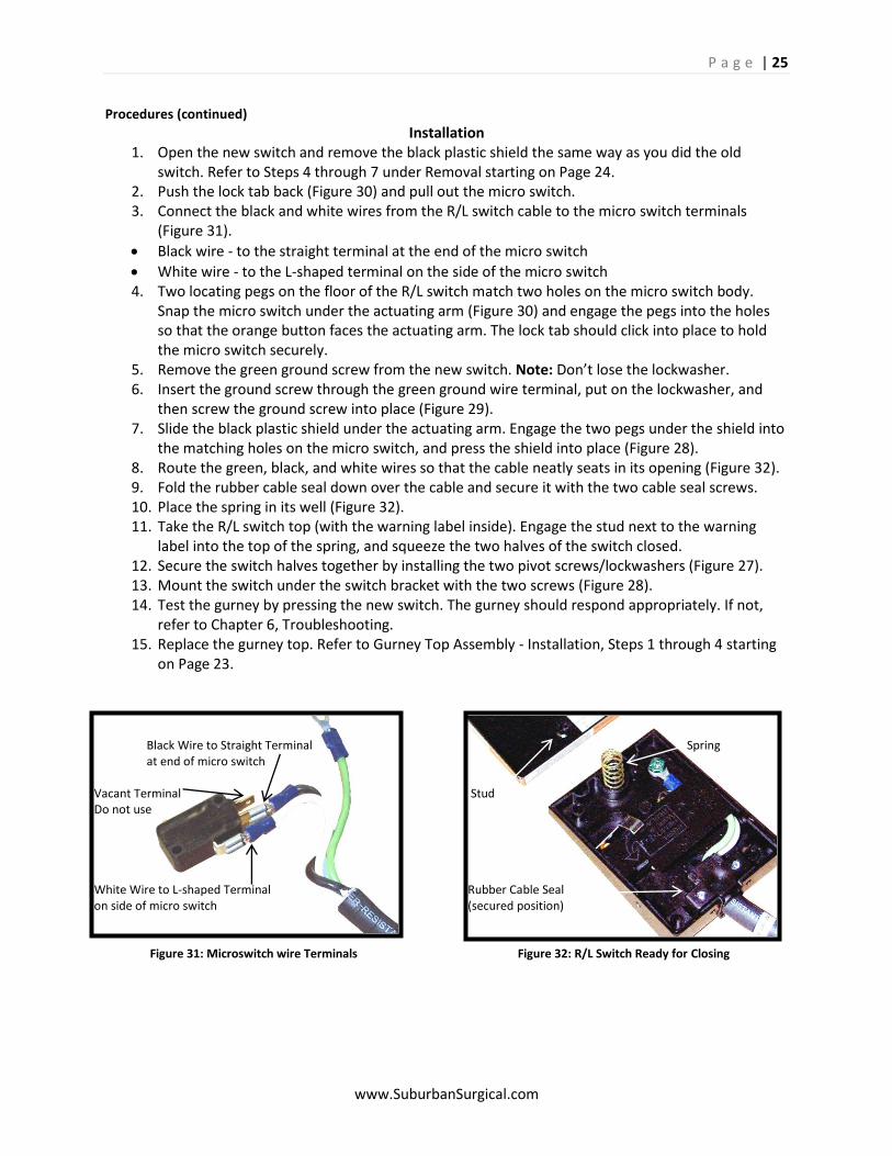
switch. Refer to Steps 4 through 7 under Removal starting on Page 24. 2. Push the lock tab back (Figure 30) and pull out the micro switch. 3. Connect the black and white wires from the R/L switch cable to the micro switch terminals
(Figure 31).
Black wire - to the straight terminal at the end of the micro switch
White wire - to the L-shaped terminal on the side of the micro switch 4. Two locating pegs on the floor of the R/L switch match two holes on the micro switch body.
Snap the micro switch under the actuating arm (Figure 30) and engage the pegs into the holes so that the orange button faces the actuating arm. The lock tab should click into place to hold the micro switch securely.
5. Remove the green ground screw from the new switch. Note: Don’t lose the lockwasher. 6. Insert the ground screw through the green ground wire terminal, put on the lockwasher, and
then screw the ground screw into place (Figure 29). 7. Slide the black plastic shield under the actuating arm. Engage the two pegs under the shield into
the matching holes on the micro switch, and press the shield into place (Figure 28). 8. Route the green, black, and white wires so that the cable neatly seats in its opening (Figure 32). 9. Fold the rubber cable seal down over the cable and secure it with the two cable seal screws. 10. Place the spring in its well (Figure 32). 11. Take the R/L switch top (with the warning label inside). Engage the stud next to the warning
label into the top of the spring, and squeeze the two halves of the switch closed. 12. Secure the switch halves together by installing the two pivot screws/lockwashers (Figure 27). 13. Mount the switch under the switch bracket with the two screws (Figure 28). 14. Test the gurney by pressing the new switch. The gurney should respond appropriately. If not,
refer to Chapter 6, Troubleshooting. 15. Replace the gurney top. Refer to Gurney Top Assembly - Installation, Steps 1 through 4 starting
on Page 23.
Black Wire to Straight Terminal Spring at end of micro switch Vacant Terminal Stud Do not use White Wire to L-shaped Terminal Rubber Cable Seal on side of micro switch (secured position)
Figure 31: Microswitch wire Terminals Figure 32: R/L Switch Ready for Closing
P a g e | 26
www.SuburbanSurgical.com
Warning: The electric ball drive actuator holds the gurney in its raised position. If the actuator is removed while the gurney is in a raised position, the gurney top will drop suddenly with considerable force. A high potential exist for injury to you or damage to the equipment. Always lay the gurney down on one side when working with electric ball drive actuator or any of its associated components. This relieves the force of gravity on the gurney and greatly enhances the safety of the procedure. Caution: The lift gurney is heavy. Lying it down on its side should be done by at least two people.
Procedures (continued)
Electric Ball Drive Actuator- P/N 854534-18
Tools & Supplies Required: ·9/16 in. wrench, ·3/4 in. open-end wrench, ·1/4 in. hex key (Allen Wrench), ·Two ½ in. wrenches, ·Flat-blade screwdriver, ·Vise grips, ·Small wire brush, ·Pipe cleaner, ·Alcohol or other solvent, ·Loctite or similar thread adhesive, ·Electrical tape
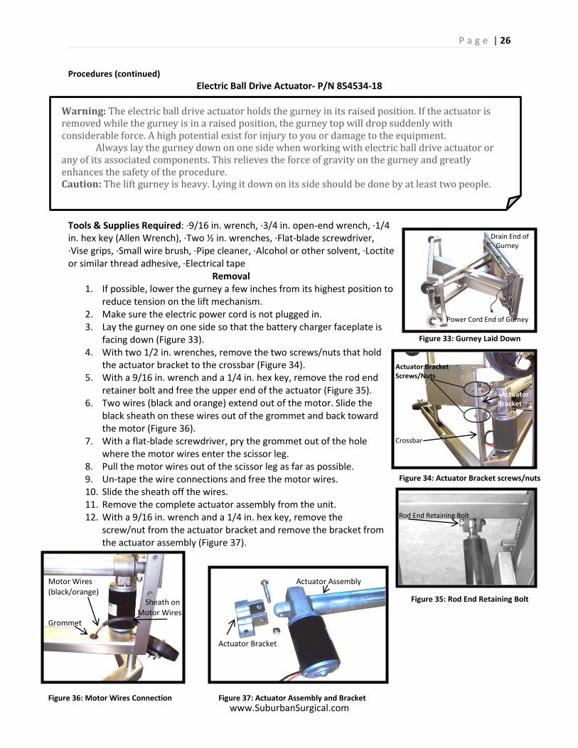
Removal 1. If possible, lower the gurney a few inches from its highest position to
reduce tension on the lift mechanism. 2. Make sure the electric power cord is not plugged in. 3. Lay the gurney on one side so that the battery charger faceplate is
facing down (Figure 33). 4. With two 1/2 in. wrenches, remove the two screws/nuts that hold
the actuator bracket to the crossbar (Figure 34). 5. With a 9/16 in. wrench and a 1/4 in. hex key, remove the rod end
retainer bolt and free the upper end of the actuator (Figure 35). 6. Two wires (black and orange) extend out of the motor. Slide the
black sheath on these wires out of the grommet and back toward the motor (Figure 36).
7. With a flat-blade screwdriver, pry the grommet out of the hole where the motor wires enter the scissor leg.
8. Pull the motor wires out of the scissor leg as far as possible. 9. Un-tape the wire connections and free the motor wires. 10. Slide the sheath off the wires. 11. Remove the complete actuator assembly from the unit. 12. With a 9/16 in. wrench and a 1/4 in. hex key, remove the
screw/nut from the actuator bracket and remove the bracket from the actuator assembly (Figure 37).
Drain End of Gurney Power Cord End of Gurney
Figure 33: Gurney Laid Down Actuator Bracket Screws/Nuts Actuator Bracket Crossbar
Figure 34: Actuator Bracket screws/nuts Rod End Retaining Bolt
Figure 35: Rod End Retaining Bolt
Motor Wires Actuator Assembly (black/orange) Sheath on Motor Wires Grommet Actuator Bracket
Figure 36: Motor Wires Connection Figure 37: Actuator Assembly and Bracket
P a g e | 27
www.SuburbanSurgical.com
Procedures (continued)
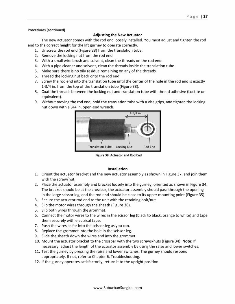
Adjusting the New Actuator The new actuator comes with the rod end loosely installed. You must adjust and tighten the rod end to the correct height for the lift gurney to operate correctly.
1. Unscrew the rod end (Figure 38) from the translation tube. 2. Remove the locking nut from the rod end. 3. With a small wire brush and solvent, clean the threads on the rod end. 4. With a pipe cleaner and solvent, clean the threads inside the translation tube. 5. Make sure there is no oily residue remaining on any of the threads. 6. Thread the locking nut back onto the rod end. 7. Screw the rod end into the translation tube until the center of the hole in the rod end is exactly
1-3/4 in. from the top of the translation tube (Figure 38). 8. Coat the threads between the locking nut and translation tube with thread adhesive (Loctite or
equivalent). 9. Without moving the rod end, hold the translation tube with a vise grips, and tighten the locking
nut down with a 3/4 in. open-end wrench.
Installation 1. Orient the actuator bracket and the new actuator assembly as shown in Figure 37, and join them
with the screw/nut. 2. Place the actuator assembly and bracket loosely into the gurney, oriented as shown in Figure 34.
The bracket should be at the crossbar, the actuator assembly should pass through the opening in the large scissor leg, and the rod end should be close to its upper mounting point (Figure 35).
3. Secure the actuator rod end to the unit with the retaining bolt/nut. 4. Slip the motor wires through the sheath (Figure 36). 5. Slip both wires through the grommet. 6. Connect the motor wires to the wires in the scissor leg (black to black, orange to white) and tape
them securely with electrical tape. 7. Push the wires as far into the scissor leg as you can. 8. Replace the grommet into the hole in the scissor leg. 9. Slide the sheath down the wires and into the grommet. 10. Mount the actuator bracket to the crossbar with the two screws/nuts (Figure 34). Note: If
necessary, adjust the length of the actuator assembly by using the raise and lower switches. 11. Test the gurney by pressing the raise and lower switches. The gurney should respond
appropriately. If not, refer to Chapter 6, Troubleshooting. 12. If the gurney operates satisfactorily, return it to the upright position.
1-3/4 in. Translation Tube Locking Nut Rod End
Figure 38: Actuator and Rod End
P a g e | 28
www.SuburbanSurgical.com
Warning: The electric ball drive actuator holds the gurney in its raised position. If the actuator is removed while the gurney is in a raised position, the gurney top will drop suddenly with considerable force. A high potential exist for injury to you or damage to the equipment. Always lay the gurney down on one side when working with electric ball drive actuator or any of its associated components. This relieves the force of gravity on the gurney and greatly enhances the safety of the procedure. Caution: The lift gurney is heavy. Lying it down on its side should be done by at least two people.
Procedures (continued)
Motor- P/N 854833
Overview Replacement of the motor requires removal of the electric ball drive actuator from the gurney. Tools & Supplies Required: ·9/16 in. wrench, ·1/4 in. hex key (Allen Wrench), ·Two ½ in. wrenches, ·3/8 in. wrench, ·Flat-blade screwdriver, ·Electrical tape
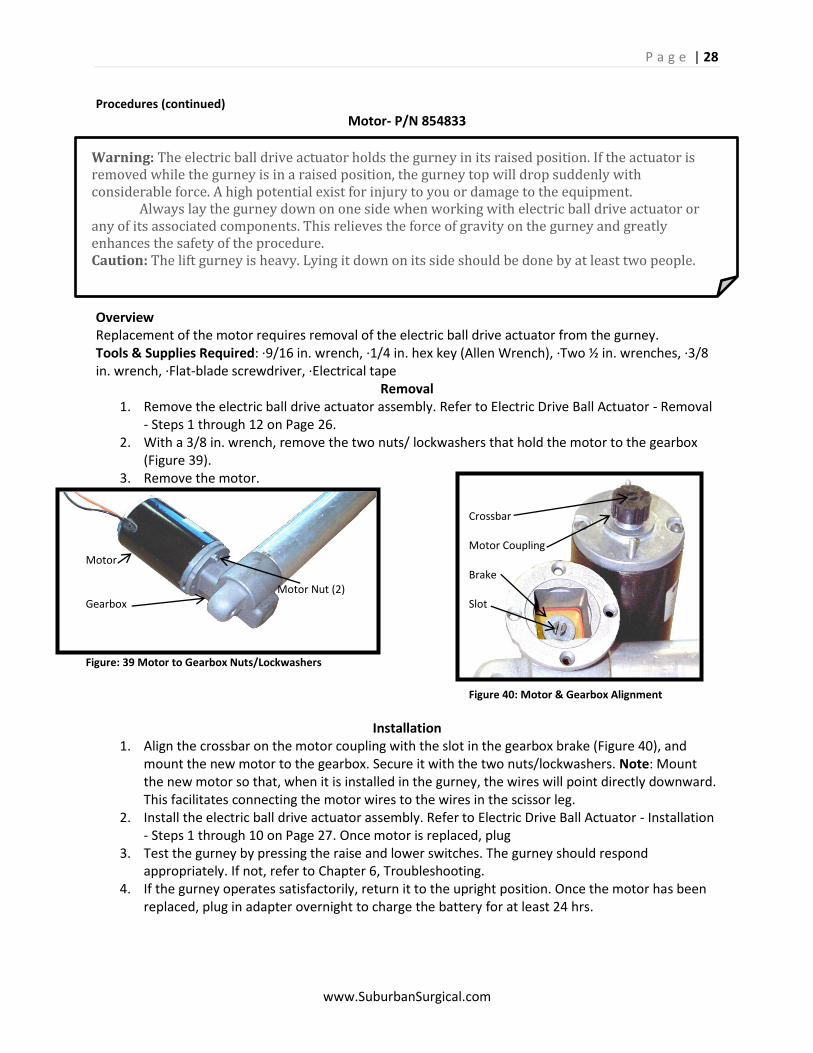
Removal 1. Remove the electric ball drive actuator assembly. Refer to Electric Drive Ball Actuator - Removal
- Steps 1 through 12 on Page 26. 2. With a 3/8 in. wrench, remove the two nuts/ lockwashers that hold the motor to the gearbox
(Figure 39). 3. Remove the motor.
Installation 1. Align the crossbar on the motor coupling with the slot in the gearbox brake (Figure 40), and
mount the new motor to the gearbox. Secure it with the two nuts/lockwashers. Note: Mount the new motor so that, when it is installed in the gurney, the wires will point directly downward. This facilitates connecting the motor wires to the wires in the scissor leg.
2. Install the electric ball drive actuator assembly. Refer to Electric Drive Ball Actuator - Installation - Steps 1 through 10 on Page 27. Once motor is replaced, plug
3. Test the gurney by pressing the raise and lower switches. The gurney should respond appropriately. If not, refer to Chapter 6, Troubleshooting.
4. If the gurney operates satisfactorily, return it to the upright position. Once the motor has been replaced, plug in adapter overnight to charge the battery for at least 24 hrs.
Crossbar Motor Coupling Motor Brake Motor Nut (2) Gearbox Slot Figure: 39 Motor to Gearbox Nuts/Lockwashers
Figure 40: Motor & Gearbox Alignment
P a g e | 29
www.SuburbanSurgical.com
Warning: The electric ball drive actuator holds the gurney in its raised position. If the actuator is removed while the gurney is in a raised position, the gurney top will drop suddenly with considerable force. A high potential exist for injury to you or damage to the equipment. Always lay the gurney down on one side when working with electric ball drive actuator or any of its associated components. This relieves the force of gravity on the gurney and greatly enhances the safety of the procedure. Caution: The lift gurney is heavy. Lying it down on its side should be done by at least two people.
Procedures (continued) Motor Coupling- P/N 854196
Overview Replacement of the motor coupling requires removal of the electric ball drive actuator from the gurney. Tools & Supplies Required: ·9/16 in. wrench, ·1/4 in. hex key (Allen Wrench), ·Two ½ in. wrenches, ·3/8 in. wrench, ·Flat-blade screwdriver, ·Electrical tape
Removal 1. Remove the electric ball drive actuator assembly. Refer to Electric Drive Ball Actuator - Removal
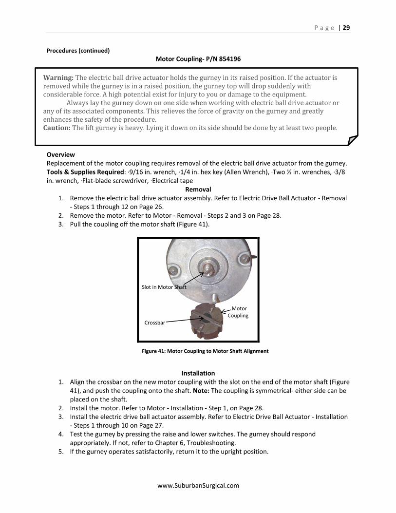
- Steps 1 through 12 on Page 26. 2. Remove the motor. Refer to Motor - Removal - Steps 2 and 3 on Page 28. 3. Pull the coupling off the motor shaft (Figure 41).
Installation 1. Align the crossbar on the new motor coupling with the slot on the end of the motor shaft (Figure
41), and push the coupling onto the shaft. Note: The coupling is symmetrical- either side can be placed on the shaft.
2. Install the motor. Refer to Motor - Installation - Step 1, on Page 28. 3. Install the electric drive ball actuator assembly. Refer to Electric Drive Ball Actuator - Installation
- Steps 1 through 10 on Page 27. 4. Test the gurney by pressing the raise and lower switches. The gurney should respond
appropriately. If not, refer to Chapter 6, Troubleshooting. 5. If the gurney operates satisfactorily, return it to the upright position.
Slot in Motor Shaft Motor Coupling Crossbar Figure 41: Motor Coupling to Motor Shaft Alignment
P a g e | 30
www.SuburbanSurgical.com
Warning: The electric ball drive actuator holds the gurney in its raised position. If the actuator is removed while the gurney is in a raised position, the gurney top will drop suddenly with considerable force. A high potential exist for injury to you or damage to the equipment. Always lay the gurney down on one side when working with electric ball drive actuator or any of its associated components. This relieves the force of gravity on the gurney and greatly enhances the safety of the procedure. Caution: The lift gurney is heavy. Lying it down on its side should be done by at least two people.
Procedures (continued) Brake- P/N 853695
Tools & Supplies Required: ·9/16 in. wrench, ·1/4 in. hex key (Allen Wrench), ·Two ½ in. wrenches, ·3/8 in. wrench, ·Flat-blade screwdriver, ·Electrical tape, ·Paper clip, 1-3/4 in. long, ·Needle-nose pliers
Removal 1. Remove the electric ball drive actuator assembly. Refer to
Electric Drive Ball Actuator - Removal - Steps 1 through 12 on Page 26.
2. Remove the motor. Refer to Motor - Removal - Steps 2 and 3 on Page 28.
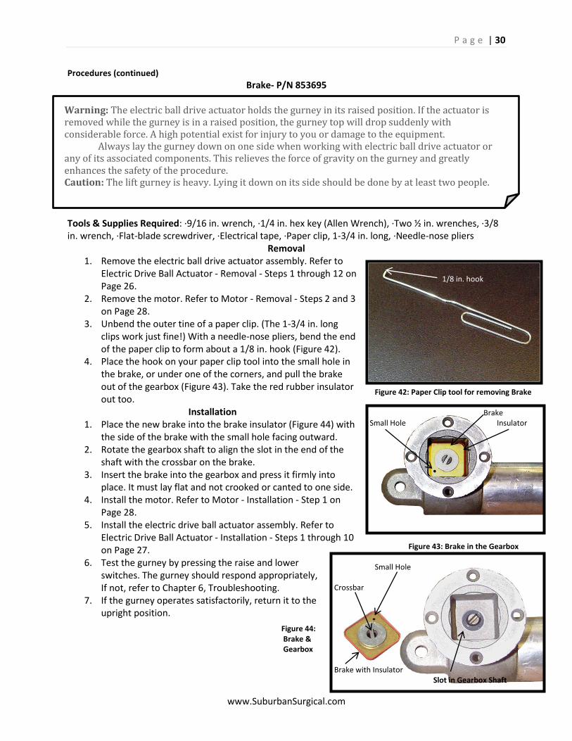
3. Unbend the outer tine of a paper clip. (The 1-3/4 in. long clips work just fine!) With a needle-nose pliers, bend the end of the paper clip to form about a 1/8 in. hook (Figure 42).
4. Place the hook on your paper clip tool into the small hole in the brake, or under one of the corners, and pull the brake out of the gearbox (Figure 43). Take the red rubber insulator out too.
Installation 1. Place the new brake into the brake insulator (Figure 44) with
the side of the brake with the small hole facing outward. 2. Rotate the gearbox shaft to align the slot in the end of the
shaft with the crossbar on the brake. 3. Insert the brake into the gearbox and press it firmly into
place. It must lay flat and not crooked or canted to one side. 4. Install the motor. Refer to Motor - Installation - Step 1 on
Page 28. 5. Install the electric drive ball actuator assembly. Refer to
Electric Drive Ball Actuator - Installation - Steps 1 through 10 on Page 27.
6. Test the gurney by pressing the raise and lower switches. The gurney should respond appropriately, If not, refer to Chapter 6, Troubleshooting.
7. If the gurney operates satisfactorily, return it to the upright position.
1/8 in. hook Figure 42: Paper Clip tool for removing Brake Brake Small Hole Insulator Figure 43: Brake in the Gearbox Small Hole Crossbar Figure 44: Brake & Gearbox Brake with Insulator Slot in Gearbox Shaft
P a g e | 31
www.SuburbanSurgical.com
Caution: Always lay the gurney down on one side when replacing a wheel/caster assembly. This is safe, and the procedure is easier to perform, than trying to lift and support the gurney at a height adequate to remove the assembly. The lift gurney is heavy. Lying it down on its side should be done by at least two people.
Procedures (continued) Wheel/Caster Assembly
Standard- P/N C008-21081111-FNF00 Stainless Steel- P/N C008-22082221-FFD00
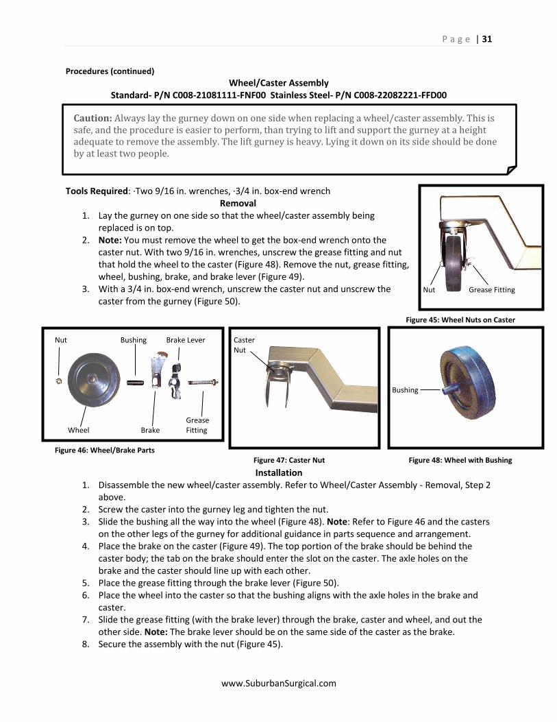
Tools Required: ·Two 9/16 in. wrenches, ·3/4 in. box-end wrench Removal
1. Lay the gurney on one side so that the wheel/caster assembly being replaced is on top.
2. Note: You must remove the wheel to get the box-end wrench onto the caster nut. With two 9/16 in. wrenches, unscrew the grease fitting and nut that hold the wheel to the caster (Figure 48). Remove the nut, grease fitting, wheel, bushing, brake, and brake lever (Figure 49).
3. With a 3/4 in. box-end wrench, unscrew the caster nut and unscrew the caster from the gurney (Figure 50).
Installation 1. Disassemble the new wheel/caster assembly. Refer to Wheel/Caster Assembly - Removal, Step 2
above. 2. Screw the caster into the gurney leg and tighten the nut. 3. Slide the bushing all the way into the wheel (Figure 48). Note: Refer to Figure 46 and the casters
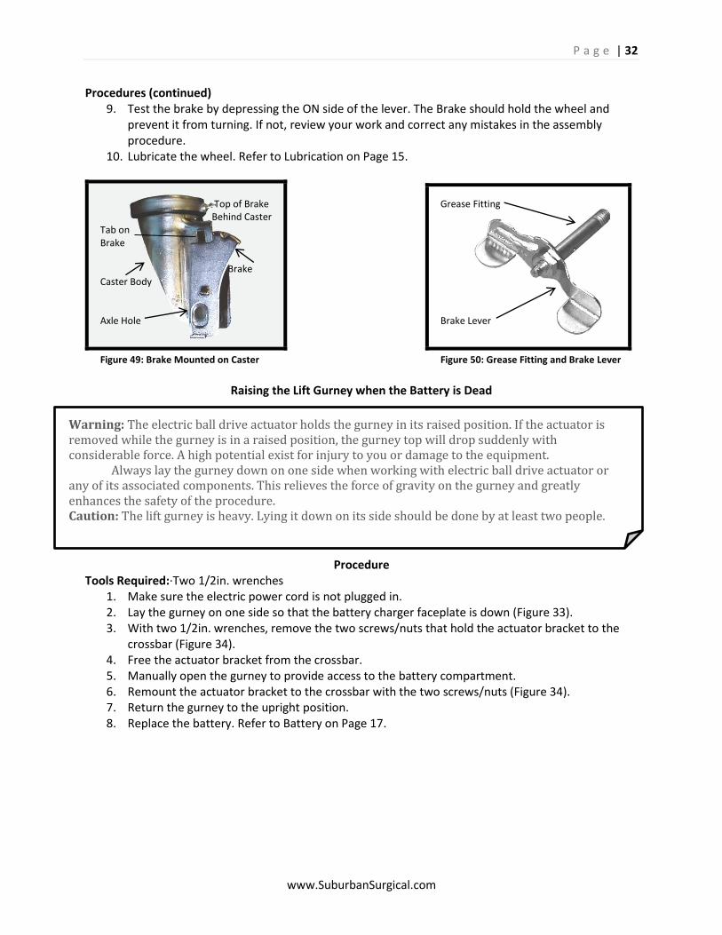
on the other legs of the gurney for additional guidance in parts sequence and arrangement. 4. Place the brake on the caster (Figure 49). The top portion of the brake should be behind the
caster body; the tab on the brake should enter the slot on the caster. The axle holes on the brake and the caster should line up with each other.
5. Place the grease fitting through the brake lever (Figure 50). 6. Place the wheel into the caster so that the bushing aligns with the axle holes in the brake and
caster. 7. Slide the grease fitting (with the brake lever) through the brake, caster and wheel, and out the
other side. Note: The brake lever should be on the same side of the caster as the brake. 8. Secure the assembly with the nut (Figure 45).
Nut Grease Fitting
Figure 45: Wheel Nuts on Caster Bushing
Figure 48: Wheel with Bushing
Nut Bushing Brake Lever Caster Nut Grease Wheel Brake Fitting Figure 46: Wheel/Brake Parts Figure 47: Caster Nut
P a g e | 32
www.SuburbanSurgical.com
Warning: The electric ball drive actuator holds the gurney in its raised position. If the actuator is removed while the gurney is in a raised position, the gurney top will drop suddenly with considerable force. A high potential exist for injury to you or damage to the equipment. Always lay the gurney down on one side when working with electric ball drive actuator or any of its associated components. This relieves the force of gravity on the gurney and greatly enhances the safety of the procedure. Caution: The lift gurney is heavy. Lying it down on its side should be done by at least two people.
Procedures (continued) 9. Test the brake by depressing the ON side of the lever. The Brake should hold the wheel and
prevent it from turning. If not, review your work and correct any mistakes in the assembly procedure.
10. Lubricate the wheel. Refer to Lubrication on Page 15.
Raising the Lift Gurney when the Battery is Dead
Procedure Tools Required:·Two 1/2in. wrenches
1. Make sure the electric power cord is not plugged in. 2. Lay the gurney on one side so that the battery charger faceplate is down (Figure 33). 3. With two 1/2in. wrenches, remove the two screws/nuts that hold the actuator bracket to the
crossbar (Figure 34). 4. Free the actuator bracket from the crossbar. 5. Manually open the gurney to provide access to the battery compartment. 6. Remount the actuator bracket to the crossbar with the two screws/nuts (Figure 34). 7. Return the gurney to the upright position. 8. Replace the battery. Refer to Battery on Page 17.
Top of Brake Grease Fitting Behind Caster Tab on Brake Brake Caster Body Axle Hole Brake Lever Figure 49: Brake Mounted on Caster Figure 50: Grease Fitting and Brake Lever
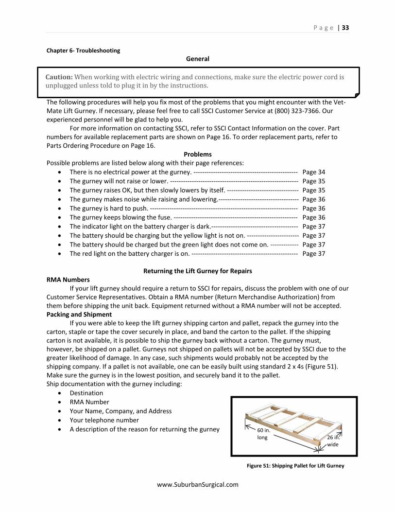
P a g e | 33
www.SuburbanSurgical.com
Caution: When working with electric wiring and connections, make sure the electric power cord is unplugged unless told to plug it in by the instructions.
Chapter 6- Troubleshooting
General
The following procedures will help you fix most of the problems that you might encounter with the Vet-Mate Lift Gurney. If necessary, please feel free to call SSCI Customer Service at (800) 323-7366. Our experienced personnel will be glad to help you. For more information on contacting SSCI, refer to SSCI Contact Information on the cover. Part numbers for available replacement parts are shown on Page 16. To order replacement parts, refer to Parts Ordering Procedure on Page 16.
Problems Possible problems are listed below along with their page references:
There is no electrical power at the gurney. ------------------------------------------------ Page 34
The gurney will not raise or lower. ----------------------------------------------------------- Page 35
The gurney raises OK, but then slowly lowers by itself. --------------------------------- Page 35
The gurney makes noise while raising and lowering.------------------------------------- Page 36
The gurney is hard to push. -------------------------------------------------------------------- Page 36
The gurney keeps blowing the fuse. --------------------------------------------------------- Page 36
The indicator light on the battery charger is dark.---------------------------------------- Page 37
The battery should be charging but the yellow light is not on. ------------------------ Page 37
The battery should be charged but the green light does not come on. ------------- Page 37
The red light on the battery charger is on. ------------------------------------------------- Page 37
Returning the Lift Gurney for Repairs RMA Numbers If your lift gurney should require a return to SSCI for repairs, discuss the problem with one of our Customer Service Representatives. Obtain a RMA number (Return Merchandise Authorization) from them before shipping the unit back. Equipment returned without a RMA number will not be accepted. Packing and Shipment If you were able to keep the lift gurney shipping carton and pallet, repack the gurney into the carton, staple or tape the cover securely in place, and band the carton to the pallet. If the shipping carton is not available, it is possible to ship the gurney back without a carton. The gurney must, however, be shipped on a pallet. Gurneys not shipped on pallets will not be accepted by SSCI due to the greater likelihood of damage. In any case, such shipments would probably not be accepted by the shipping company. If a pallet is not available, one can be easily built using standard 2 x 4s (Figure 51). Make sure the gurney is in the lowest position, and securely band it to the pallet. Ship documentation with the gurney including:
Destination
RMA Number
Your Name, Company, and Address
Your telephone number
A description of the reason for returning the gurney
60 in. long 26 in. wide
Figure 51: Shipping Pallet for Lift Gurney
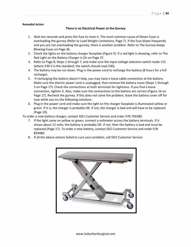
P a g e | 34
www.SuburbanSurgical.com
Remedial Action
There is no Electrical Power at the Gurney
1. Wait ten seconds and press the fuse to reset it. The most common cause of blown fuses is overloading the gurney (Refer to Load Weight Limitations, Page 7). If the fuse blows frequently and you are not overloading the gurney, there is another problem. Refer to The Gurney Keeps Blowing Fuses on Page 36.
2. Check the lights on the battery charger faceplate (Figure 5). If a red light is showing, refer to The Red Light on the Battery Charger is On on Page 37.
3. Refer to Page 8, Steps 1 through 7, and make sure the input voltage selection switch reads 115 (where 230 V is the standard, the switch should read 230).
4. The battery may be run down. Plug in the power cord to recharge the battery (8 hours for a full recharge).
5. If recharging the battery doesn’t help, you may have a loose cable connection at the battery. Make sure the electric power cord is unplugged, then remove the battery cover (Steps 1 through 3 on Page 17). Check the connections at both terminals for tightness. If you find a loose connection, tighten it. Also, make sure the connections to the battery are correct (Figure 16 on Page 17). Recheck the gurney. If this does not solve the problem, leave the battery cover off for now while you try the following solutions.
6. Plug in the power cord and make sure the light on the charger faceplate is illuminated yellow or green. If it is, the charger is probably OK. If not, the charger is bad and will have to be replaced (Page 19).
To order a new battery charger, contact SSCI Customer Service and order P/N 756580. 7. If the light came on yellow or green, connect a voltmeter across the battery terminals. If it
shows about 12 volts, the battery is probably OK. If not, then the battery is bad and must be replaced (Page 17). To order a new battery, contact SSCI Customer Service and order P/N 854480.
8. If all the above actions failed to cure your problem, call SSCI Customer Service.
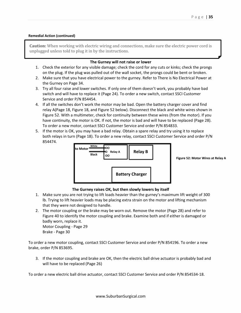
P a g e | 35
www.SuburbanSurgical.com
Caution: When working with electric wiring and connections, make sure the electric power cord is unplugged unless told to plug it in by the instructions.
Remedial Action (continued)
The Gurney will not raise or lower 1. Check the exterior for any visible damage; check the cord for any cuts or kinks; check the prongs
on the plug. If the plug was pulled out of the wall socket, the prongs could be bent or broken. 2. Make sure that you have electrical power to the gurney. Refer to There is No Electrical Power at
the Gurney on Page 34. 3. Try all four raise and lower switches. If only one of them doesn’t work, you probably have bad
switch and will have to replace it (Page 24). To order a new switch, contact SSCI Customer Service and order P/N 854454.
4. If all the switches don’t work the motor may be bad. Open the battery charger cover and find relay A(Page 18, Figure 18, and Figure 52 below). Disconnect the black and white wires shown in Figure 52. With a multimeter, check for continuity between these wires (from the motor). If you have continuity, the motor is OK. If not, the motor is bad and will have to be replaced (Page 28). To order a new motor, contact SSCI Customer Service and order P/N 854833.
5. If the motor is OK, you may have a bad relay. Obtain a spare relay and try using it to replace both relays in turn (Page 18). To order a new relay, contact SSCI Customer Service and order P/N 854474.
The Gurney raises OK, but then slowly lowers by itself 1. Make sure you are not trying to lift loads heavier than the gurney’s maximum lift weight of 300
lb. Trying to lift heavier loads may be placing extra strain on the motor and lifting mechanism that they were not designed to handle.
2. The motor coupling or the brake may be worn out. Remove the motor (Page 28) and refer to Figure 40 to identify the motor coupling and brake. Examine both and if either is damaged or badly worn, replace it.
Motor Coupling - Page 29 Brake - Page 30 To order a new motor coupling, contact SSCI Customer Service and order P/N 854196. To order a new brake, order P/N 853695.
3. If the motor coupling and brake are OK, then the electric ball drive actuator is probably bad and will have to be replaced (Page 26)
To order a new electric ball drive actuator, contact SSCI Customer Service and order P/N 854534-18.
Battery Charger
Relay B OO O Relay A OO
White
Black
to Motor
Figure 52: Motor Wires at Relay A
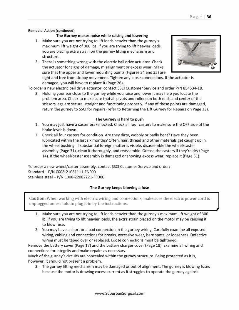
P a g e | 36
www.SuburbanSurgical.com
Caution: When working with electric wiring and connections, make sure the electric power cord is unplugged unless told to plug it in by the instructions.
Remedial Action (continued) The Gurney makes noise while raising and lowering
1. Make sure you are not trying to lift loads heavier than the gurney’s maximum lift weight of 300 lbs. If you are trying to lift heavier loads, you are placing extra strain on the gurney lifting mechanism and structure.
2. There is something wrong with the electric ball drive actuator. Check the actuator for signs of damage, misalignment or excess wear. Make sure that the upper and lower mounting points (Figures 34 and 35) are tight and free from sloppy movement. Tighten any loose connections. If the actuator is damaged, you will have to replace it (Page 26).
To order a new electric ball drive actuator, contact SSCI Customer Service and order P/N 854534-18. 3. Holding your ear close to the gurney while you raise and lower it may help you locate the
problem area. Check to make sure that all pivots and rollers on both ends and center of the scissors legs are secure, straight and functioning properly. If any of these points are damaged, return the gurney to SSCI for repairs (refer to Returning the Lift Gurney for Repairs on Page 33).
The Gurney is hard to push 1. You may just have a caster brake locked. Check all four casters to make sure the OFF side of the
brake lever is down. 2. Check all four casters for condition. Are they dirty, wobbly or badly bent? Have they been
lubricated within the last six months? Often, hair, thread and other materials get caught up in the wheel bushing. If substantial foreign matter is visible, disassemble the wheel/caster assembly (Page 31), clean it thoroughly, and reassemble. Grease the casters if they’re dry (Page 14). If the wheel/caster assembly is damaged or showing excess wear, replace it (Page 31).
To order a new wheel/caster assembly, contact SSCI Customer Service and order: Standard – P/N C008-21081111-FNF00 Stainless steel – P/N C008-22082221-FFD00
The Gurney keeps blowing a fuse
1. Make sure you are not trying to lift loads heavier than the gurney’s maximum lift weight of 300 lb. If you are trying to lift heavier loads, the extra strain placed on the motor may be causing it to blow fuse.
2. You may have a short or a bad connection in the gurney wiring. Carefully examine all exposed wiring, cabling and connections for breaks, excessive wear, bare spots, or looseness. Defective wiring must be taped over or replaced. Loose connections must be tightened.
Remove the battery cover (Page 17) and the battery charger cover (Page 18). Examine all wiring and connections for integrity and make repairs as necessary. Much of the gurney’s circuits are concealed within the gurney structure. Being protected as it is, however, it should not present a problem.
3. The gurney lifting mechanism may be damaged or out of alignment. The gurney is blowing fuses because the motor is drawing excess current as it struggles to operate the gurney against
P a g e | 37
www.SuburbanSurgical.com
Caution: When working with the power supply, make sure the electric power cord is unplugged.
Caution: When working with the power supply, make sure the electric power cord is unplugged.
abnormal resistance. This is especially possible if the gurney has been severely struck by any sizeable object or has itself been rammed into a wall or other solid object.
Visually examine the entire gurney looking for damaged or misaligned structural components. Try to operate the gurney and, listening carefully, pinpoint problem areas by ear. Minor misalignment may be corrected by loosening retaining bolts and then retightening them. Major damage will require return of the gurney to SSCI for repairs (refer to Returning the Lift Gurney for Repairs on Page 33).
The Indicator light on the battery charger is dark
1. Make sure that the electric power cord is plugged in and the incoming power is correct. For example, is the receptacle controlled by a light switch?
2. Check the battery charger fuse and replace if necessary. Refer to Replacing a Battery Charger Fuse on Page 20.
3. If everything else appears normal, there is a malfunction in the battery charger itself. Call SSCI Customer Service.
The Battery should be charging but the Yellow light is on
If the charger will not go into the charge mode, the battery is probably already dead.
The Battery should be charged but the Green light does not come on If after 24 hours on the charger, the green light does not come, the battery is not accepting a charge and is probably damaged. Replace the battery.
The Red light on the Battery charger is on
1. A red light showing on the battery charger usually means that polarity to the charger is reversed. This is most likely to occur after the battery has been replaced, and means that the battery wires have been connected to the wrong terminals.
Open the battery cover (Page 17) and make sure the wires are connected to the correct terminals (Page 17).
2. If switched terminal wires are not the problem, there is a malfunction in the battery charger itself. Try replacing the battery charger fuse. Refer to Replacing a Battery Charger Fuse on Page 20.
3. If replacing the fuse does not fix the problem, the charger is probably malfunctioning. Call SSCI Customer Service.
Note: A nearly completely dead battery looks like a short to the charger. If you suspect the battery is dead, leave the charger on the battery to see if it will go into the charge mode. The charger will deliver a small amount of current and may eventually go into the normal charge mode and recover the battery. If the charger will not go into the charge mode (yellow light) within one hour, and then into the charge mode with 24 hours (green light) the battery is probably damaged beyond recovery. Replace the battery.

P a g e | 38
www.SuburbanSurgical.com

P a g e | 39
www.SuburbanSurgical.com
© Copyright 2013 by Suburban Surgical Co., Inc. All rights reserved. No part of this document may be reproduced or utilized in any form or by any means, electronic or mechanical,
including photocopying, recording, or by any information storage and retrieval system without written permission.
Inquiries should be addressed to Suburban Surgical Co., Inc. Wheeling, Illinois 60090