Refrigeration and Air Conditioning Lab Manual
25
VIDYA PRATISHTHAN’S COLLEGE OF ENGINEERING, BARAMATI DEPARTMENT OF MECHANICAL ENGINEERING LABORATORY MANUAL SUBJECT: REFRIGERATION AND AIR-CONDITIONING [SUBJECT CODE: 302051] CLASS: T.E. MECHANICAL YEAR: 2011-12 APPROVED BY: H.o.D. [Mech] PRINCIPAL Prof. P. R. Shinde Dr. S. B. Deosarkar VALIDITY UP TO: ACADEMIC YEAR 2012 – 2013 PRAPARED BY: PROF. P. R. Chitragar, K.M. Jadhav
-
Upload
shalini-manchikatla -
Category
Documents
-
view
1.299 -
download
107
description
Refrigeration and Air Conditioning Lab Manual
Transcript of Refrigeration and Air Conditioning Lab Manual
VIDYA PRATISHTHAN’S
COLLEGE OF ENGINEERING, BARAMATI
DEPARTMENT OF MECHANICAL ENGINEERING
LABORATORY MANUAL
SUBJECT: REFRIGERATION AND AIR-CONDITIONING
[SUBJECT CODE: 302051]
CLASS: T.E. MECHANICAL
YEAR: 2011-12
APPROVED BY: H.o.D. [Mech] PRINCIPAL Prof. P. R. Shinde Dr. S. B. Deosarkar
VALIDITY UP TO: ACADEMIC YEAR 2012 – 2013
PRAPARED BY: PROF. P. R. Chitragar, K.M. Jadhav
VIDYA PRATISHTHAN’S
COLLEGE OF ENGINEERING, BARAMATI
DEPARTMENT OF MECHANICAL ENGINEERING
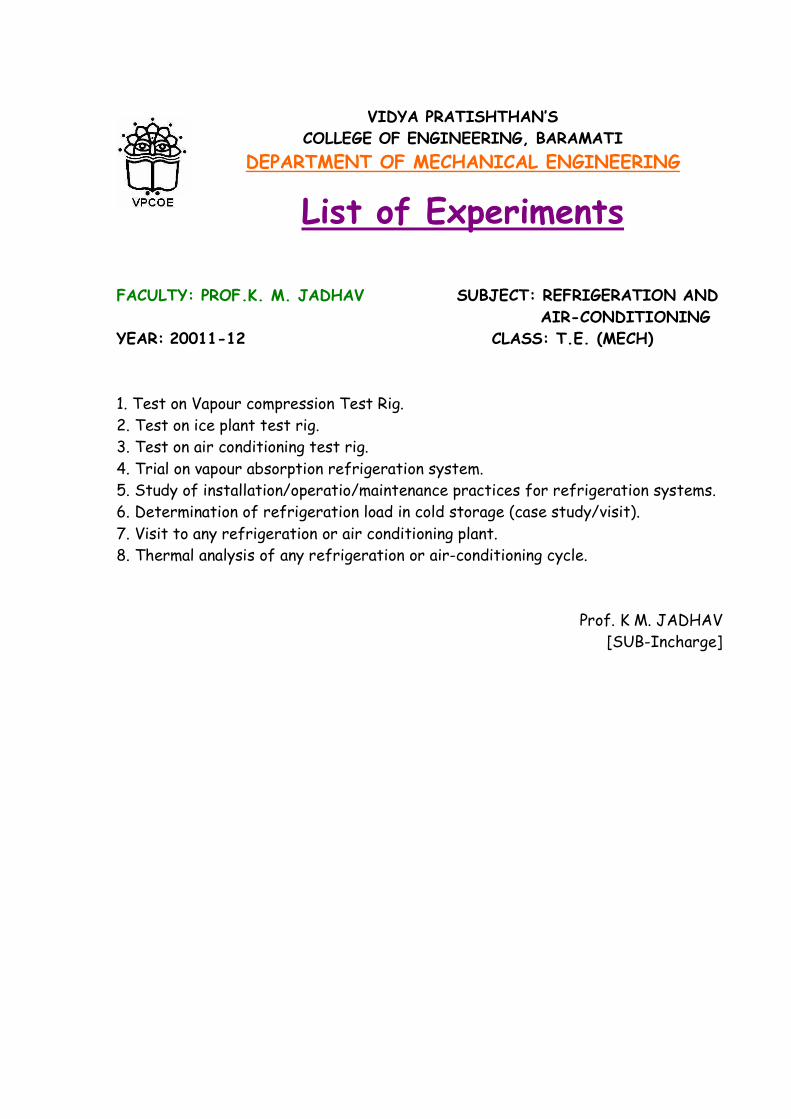
List of Experiments
FACULTY: PROF.K. M. JADHAV SUBJECT: REFRIGERATION AND
AIR-CONDITIONING
YEAR: 20011-12 CLASS: T.E. (MECH)
1. Test on Vapour compression Test Rig.
2. Test on ice plant test rig.
3. Test on air conditioning test rig.
4. Trial on vapour absorption refrigeration system.
5. Study of installation/operatio/maintenance practices for refrigeration systems.
6. Determination of refrigeration load in cold storage (case study/visit).
7. Visit to any refrigeration or air conditioning plant.
8. Thermal analysis of any refrigeration or air-conditioning cycle.
Prof. K M. JADHAV
[SUB-Incharge]
REFRIGERATION AND AIR-CONDITIONING – LABORATORY MANUAL
DEPARTMENT OF MECHANICAL ENGINEERING - VPCOE
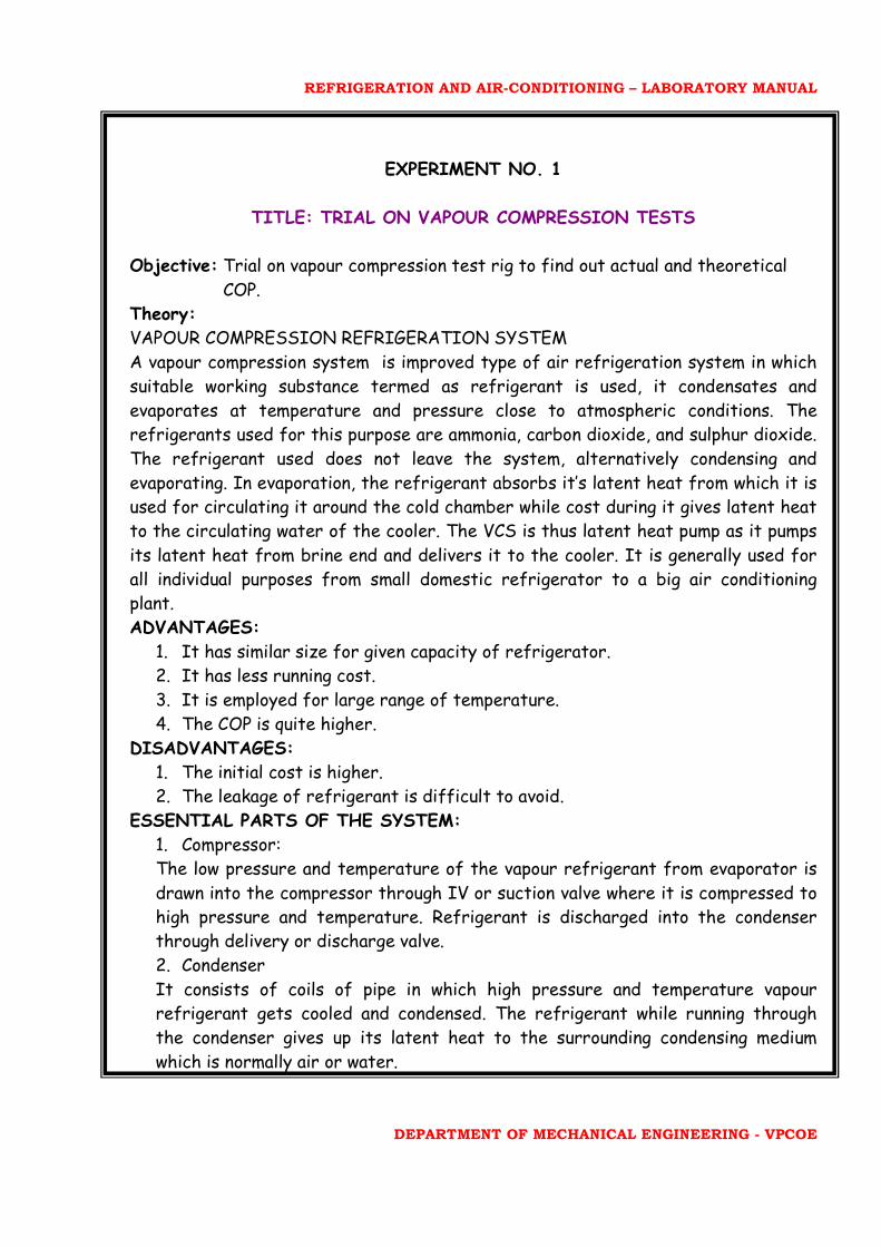
EXPERIMENT NO. 1
TITLE: TRIAL ON VAPOUR COMPRESSION TESTS Objective: Trial on vapour compression test rig to find out actual and theoretical
COP. Theory: VAPOUR COMPRESSION REFRIGERATION SYSTEM
A vapour compression system is improved type of air refrigeration system in which
suitable working substance termed as refrigerant is used, it condensates and
evaporates at temperature and pressure close to atmospheric conditions. The refrigerants used for this purpose are ammonia, carbon dioxide, and sulphur dioxide.
The refrigerant used does not leave the system, alternatively condensing and
evaporating. In evaporation, the refrigerant absorbs it’s latent heat from which it is used for circulating it around the cold chamber while cost during it gives latent heat to the circulating water of the cooler. The VCS is thus latent heat pump as it pumps
its latent heat from brine end and delivers it to the cooler. It is generally used for all individual purposes from small domestic refrigerator to a big air conditioning plant.
ADVANTAGES:
1. It has similar size for given capacity of refrigerator. 2. It has less running cost. 3. It is employed for large range of temperature. 4. The COP is quite higher.
DISADVANTAGES:
1. The initial cost is higher. 2. The leakage of refrigerant is difficult to avoid.
ESSENTIAL PARTS OF THE SYSTEM:
1. Compressor: The low pressure and temperature of the vapour refrigerant from evaporator is
drawn into the compressor through IV or suction valve where it is compressed to high pressure and temperature. Refrigerant is discharged into the condenser through delivery or discharge valve.
2. Condenser It consists of coils of pipe in which high pressure and temperature vapour refrigerant gets cooled and condensed. The refrigerant while running through
the condenser gives up its latent heat to the surrounding condensing medium
which is normally air or water.

REFRIGERATION AND AIR-CONDITIONING – LABORATORY MANUAL
DEPARTMENT OF MECHANICAL ENGINEERING - VPCOE
3. Receiver The condensed liquid refrigerant from the condenser is stored in vessel known as
receiver from where it is supplied to the evaporator through the expansion valve. 4. Expansion Valve: It allows the liquid refrigerant under high pressure and temperature to pass at a
controlled rate after reducing its pressure and temperature. Some of the refrigerants evaporate and pass through expansion valve but their greater portion is vapourised in the evaporator at low pressures and temperatures.
5. Evaporator: It consists of coils of pipe in which the liquid refrigerant at low pressure and
temperature. In evaporation, the liquid vapour refrigerant absorbs its latent heat of vapourisation from the medium which is to be cooled.
ANALYSIS OF VAPOUR COMPRESSION SYSTEM:
It depends upon: 1. Load on refrigerant plant in Tonnes.
2. Temperature of refrigerant. 3. Atmospheric temperature.
The temperature of refrigerant required and atmospheric conditions decide the
temperature of the refrigerant entering into the condenser and automatically it
decides the pressure ratio. Similarly, the working cycle is represented on T-S and P-h diagram, where the
process 3-2 represents superheating and 4-5 represents undercooling. The COP of
this cycle increases as it approaches near to the Carnot cycle. This is explained as
follows: The absorption of heat in evaporation and rejection of heat in the condenser are in the form of the latent heat. This heat transfer is carried out by maintaining the
temperatures differences as low as possible in evaporator and condenser. By comparing with the refrigerant cycle where high temperature cycle is necessary to carry out into compressor isolating it from the atmosphere. Irreversibility only
exists in the throttling process. The VCS approaches Carnot cycle as compared with air refrigeration system and COP of VCS is higher than air refrigeration system.
SPECIFICATIONS:
1. Cooling capacity: 30 kg of ice in 24 hours. 2. Insulation: PUF Insulation 3. Number of ice cans: 12 4. Size of tank: (0.83*0.345*0.345) m3.
REFRIGERATION AND AIR-CONDITIONING – LABORATORY MANUAL
DEPARTMENT OF MECHANICAL ENGINEERING - VPCOE
5. Height of the tank: 0.27 m 6. Size of the ice can: (0.325*0.116*0.078) m3.
PROCEDURE:
1. Fill the tank in vapour compression test rig with the brine solution.
2. Switch ON the main supply. 3. Start the compressor and stirrer supply button. 4. Take initial energy meter reading of both compressor and stirrer. 5. Wait for about 50 minutes so that the system gets stabilized.
6. After stabilization take all readings at required temperature. 7. Measure evaporator (L.P) and condenser (H.P) pressures.
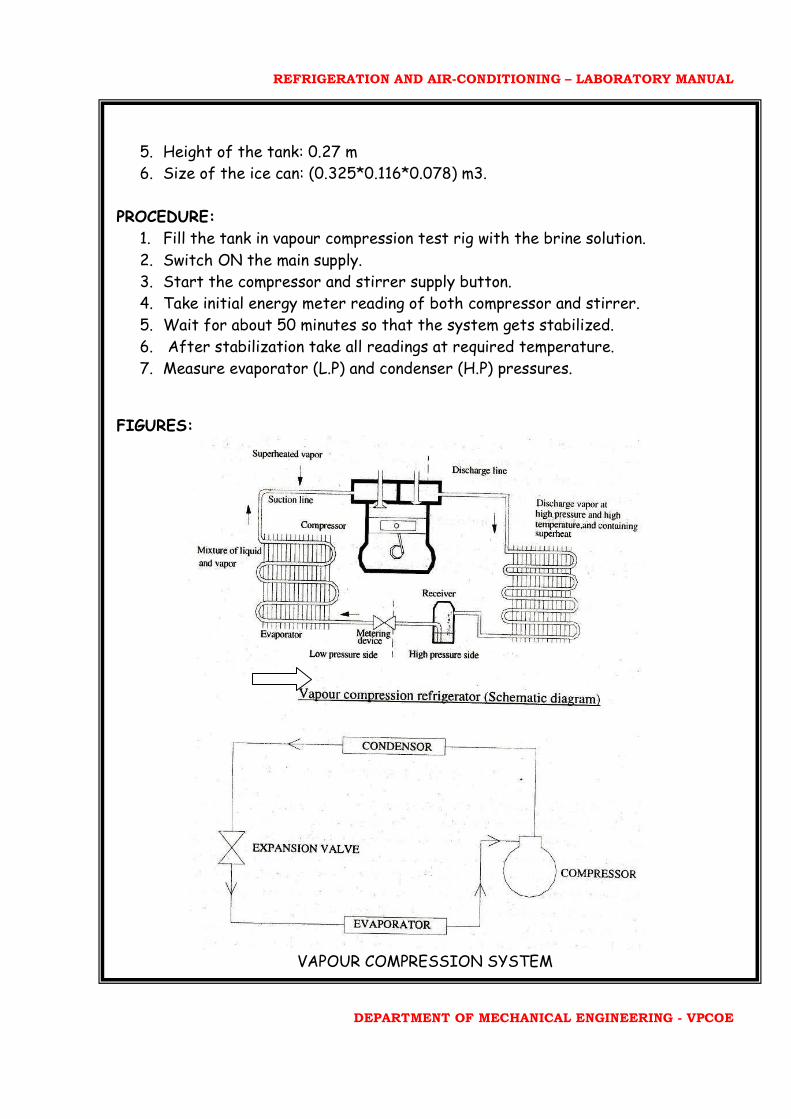
FIGURES:
VAPOUR COMPRESSION SYSTEM
REFRIGERATION AND AIR-CONDITIONING – LABORATORY MANUAL
DEPARTMENT OF MECHANICAL ENGINEERING - VPCOE
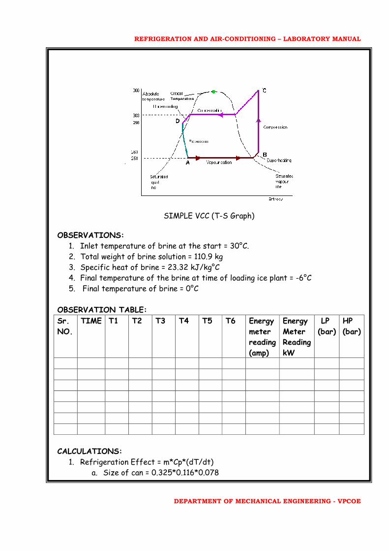
SIMPLE VCC (T-S Graph) OBSERVATIONS:
1. Inlet temperature of brine at the start = 30°C.
2. Total weight of brine solution = 110.9 kg 3. Specific heat of brine = 23.32 kJ/kg°C 4. Final temperature of the brine at time of loading ice plant = -6°C 5. Final temperature of brine = 0°C
OBSERVATION TABLE:
Sr.
NO.
TIME T1 T2 T3 T4 T5 T6 Energy
meter
reading
(amp)
Energy
Meter
Reading
kW
LP
(bar)
HP
(bar)
CALCULATIONS:
1. Refrigeration Effect = m*Cp*(dT/dt) a. Size of can = 0.325*0.116*0.078
REFRIGERATION AND AIR-CONDITIONING – LABORATORY MANUAL
DEPARTMENT OF MECHANICAL ENGINEERING - VPCOE
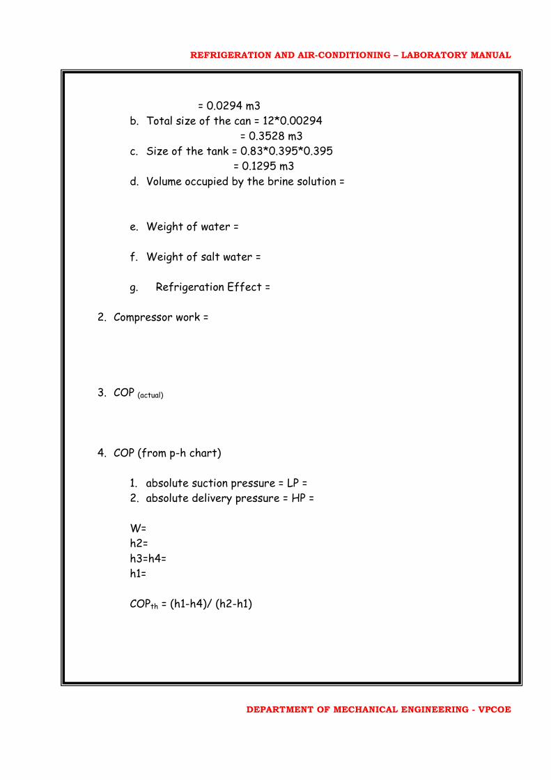
= 0.0294 m3 b. Total size of the can = 12*0.00294 = 0.3528 m3 c. Size of the tank = 0.83*0.395*0.395 = 0.1295 m3
d. Volume occupied by the brine solution =
e. Weight of water =
f. Weight of salt water =
g. Refrigeration Effect =
2. Compressor work =
3. COP (actual)
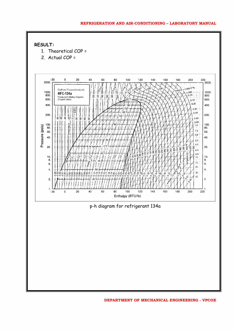
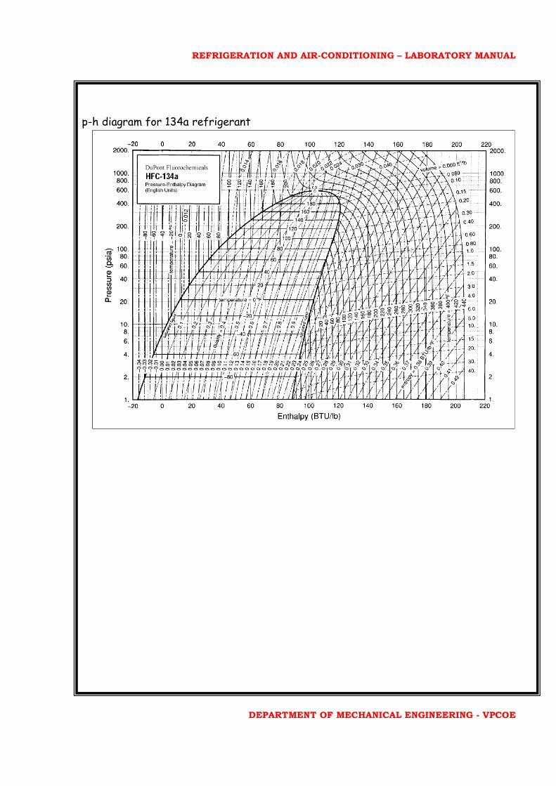
4. COP (from p-h chart)
1. absolute suction pressure = LP = 2. absolute delivery pressure = HP = W= h2=
h3=h4= h1=
COPth = (h1-h4)/ (h2-h1)
REFRIGERATION AND AIR-CONDITIONING – LABORATORY MANUAL
DEPARTMENT OF MECHANICAL ENGINEERING - VPCOE
RESULT:
1. Theoretical COP =
2. Actual COP =
p-h diagram for refrigerant 134a
REFRIGERATION AND AIR-CONDITIONING – LABORATORY MANUAL
DEPARTMENT OF MECHANICAL ENGINEERING - VPCOE
EXPERIMENT NO. 2
TITLE: TEST ON ICE PLANT TEST RIG
Objective: 1. Test on ice formation
2. Calculation of actual and theoretical COP
Apparatus: Ice plant test rig.
Specifications:
1. Compressor: hermetically sealed kirloskar made. 2. Condensor: Forced convection air cooled 3. Expansion valve: thermostatic expansion valve 4. Evaporator: Immerse type direct expansion 5. Cooling capacity: 30 kg of ice in 24 hours 6. Insulation: PUF insulation 7. Number of ice cans: 12 8. Flowmeter: GPs flow make rotameter 9. Size of tank: 0.83*0.395*0.395 m3. 10. Size of ice can: 0.35*0.166*0.078 m3.
Procedure:
1. Place machine in proper position where its level is horizontal and it is well insulated.
2. Machine must have atleast 1.5 m clearance from all sides. 3. Give 230 V, 50 Hz, 1 phase supply. 4. Prepare brine solution of water with approximate 20% of NaCl and mix it
thoroughly with water in the tank.
5. Start the compressor by putting switch ON. 6. Check the solution and discharge pressure and note down energy meter
reading.
7. Allow unit to run for some hours to bring down the temperature of brine in the range of -15°C to -120°C.
8. After attaining the temperature, fill ice can with water in each can and insert the ice can.
9. Now start agitator. Take all the readings of temperature at various point and pressure flow rate.
REFRIGERATION AND AIR-CONDITIONING – LABORATORY MANUAL
DEPARTMENT OF MECHANICAL ENGINEERING - VPCOE
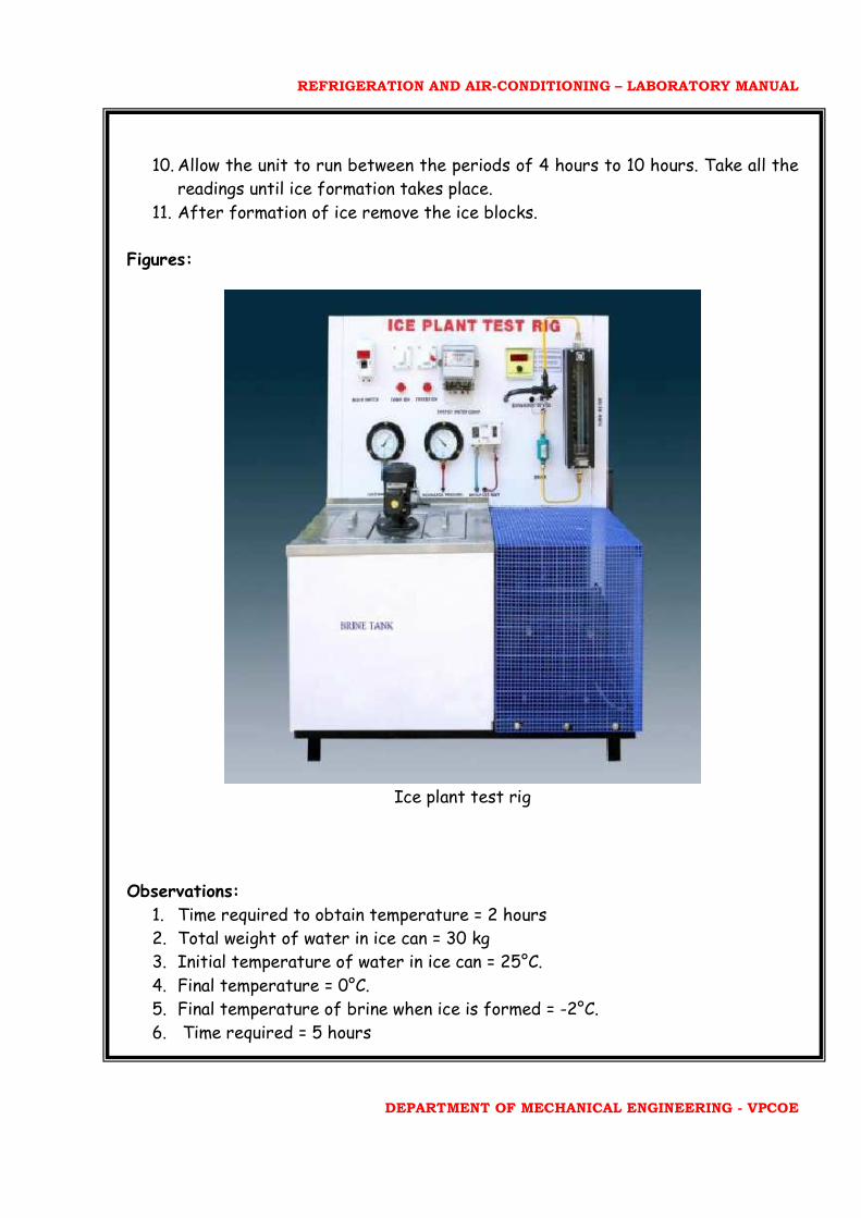
10. Allow the unit to run between the periods of 4 hours to 10 hours. Take all the readings until ice formation takes place.
11. After formation of ice remove the ice blocks.
Figures:
Ice plant test rig
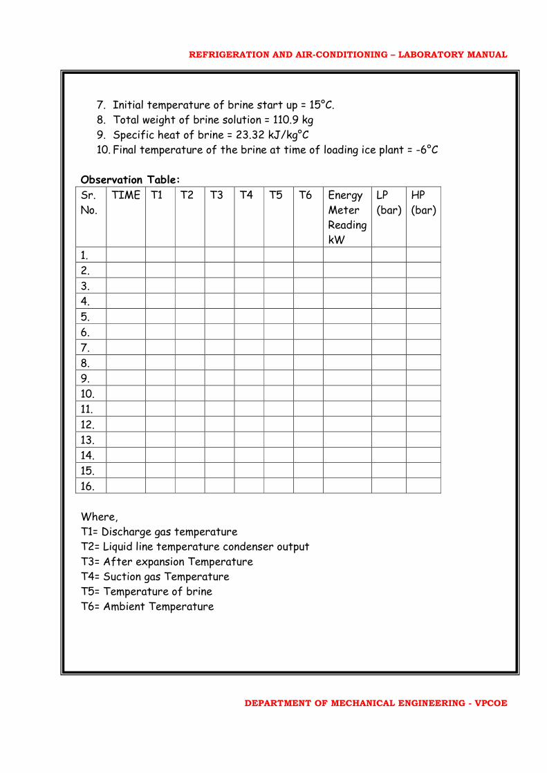
Observations:
1. Time required to obtain temperature = 2 hours 2. Total weight of water in ice can = 30 kg 3. Initial temperature of water in ice can = 25°C. 4. Final temperature = 0°C. 5. Final temperature of brine when ice is formed = -2°C. 6. Time required = 5 hours
REFRIGERATION AND AIR-CONDITIONING – LABORATORY MANUAL
DEPARTMENT OF MECHANICAL ENGINEERING - VPCOE
7. Initial temperature of brine start up = 15°C. 8. Total weight of brine solution = 110.9 kg 9. Specific heat of brine = 23.32 kJ/kg°C 10. Final temperature of the brine at time of loading ice plant = -6°C
Observation Table:
Sr.
No.
TIME T1 T2 T3 T4 T5 T6 Energy
Meter
Reading
kW
LP
(bar)
HP
(bar)
1.
2.
3.
4.
5.
6.
7.
8.
9.
10.
11.
12.
13.
14.
15.
16.
Where,
T1= Discharge gas temperature
T2= Liquid line temperature condenser output
T3= After expansion Temperature
T4= Suction gas Temperature
T5= Temperature of brine
T6= Ambient Temperature
REFRIGERATION AND AIR-CONDITIONING – LABORATORY MANUAL
DEPARTMENT OF MECHANICAL ENGINEERING - VPCOE
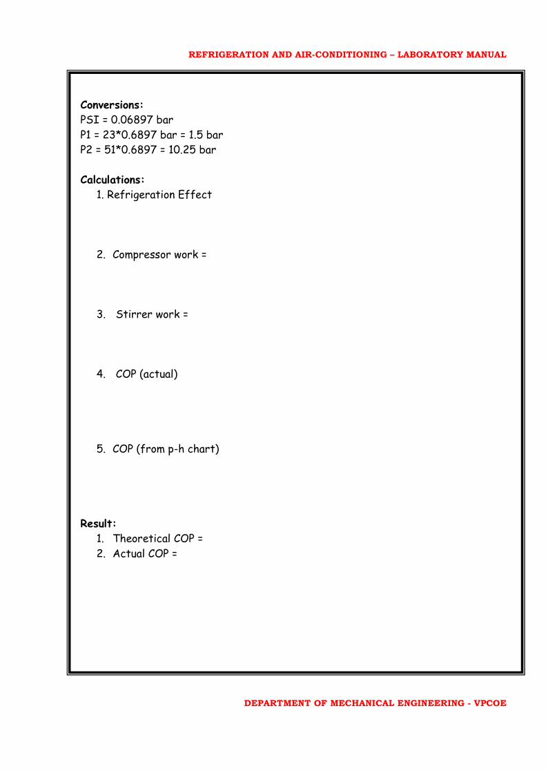
Conversions:
PSI = 0.06897 bar
P1 = 23*0.6897 bar = 1.5 bar
P2 = 51*0.6897 = 10.25 bar
Calculations:
1. Refrigeration Effect
2. Compressor work =
3. Stirrer work =
4. COP (actual)
5. COP (from p-h chart)
Result:
1. Theoretical COP = 2. Actual COP =
REFRIGERATION AND AIR-CONDITIONING – LABORATORY MANUAL
DEPARTMENT OF MECHANICAL ENGINEERING - VPCOE
p-h diagram for 134a refrigerant
REFRIGERATION AND AIR-CONDITIONING – LABORATORY MANUAL
DEPARTMENT OF MECHANICAL ENGINEERING - VPCOE
EXPERIMENT NO. 3
TITLE: TEST ON AIR CONDITIONING TEST RIG
Objective:
1. Study of vapour compression cycle for conditioner.
2. To calculate actual COP.
3. To study different air conditioning processes:
a. Humidification
b. Dehumidification
c. Cooling
d. Heating
e. Heating and Humidification
f. Heating and Dehumidification
g. Cooling and Humidification
h. Cooling and Dehumidification
Apparatus: Air conditioning test rig.
Specifications:
1. Compressor: hermetically sealed Kirloskar made.
2. Condensor: Forced convection air cooled
3. Expansion valve: thermostatic expansion valve
4. Evaporator: Immerse type direct expansion
5. Flowmeter: GPs flow make rotameter
6. Condensor and Evaporator fan: Axial flow type
7. Heater: 1000W
8. Animometer: Digital type
Theory:
Simple Vapour Compression
Figure shows the schematic diagram of simple vapour compression refrigeration
system.
It consists of following parts:
1. Compressor
The low pressure and temperature of refrigerant from the evaporator is drawn into
the compressor through the inlet and suction valve as it is compressed to high
REFRIGERATION AND AIR-CONDITIONING – LABORATORY MANUAL
DEPARTMENT OF MECHANICAL ENGINEERING - VPCOE
temperature and pressure. This high temperature and pressure vapour refrigerant is
discharged into the condenser through the delivery pipe.
2. Condensor
The condenser or cooler consists of pipe in which the high pressure and temperature
refrigerant is cooled and condensed. The refrigerant while passing through the
condenser gives up heat to the surrounding which consists of condensing medium
which is normally air or water.
3. Receiver
The condenser liquid refrigerant from the condenser is stored in a vessel known as
receiver from where it is supplied to evaporator through expansion valve or
refrigeration control valve.
4. Expansion valve
It is also called as throttle valve and its use is to allow the refrigerant under high
temperature and pressure to pass at controlled rate after reducing its high
temperature and pressure some of the refrigerant evaporates as it passes through
the expansion valve and the graded portion is vapourised in the evaporator at low
temperature and pressure.
5. Evaporator
It consists of coils of pipe in which the liquid vapour refrigerant at low pressure and
temperature is evaporated and changed to the vapour refrigerant at low
temperature and pressure. In evaporating the liquid vapour refrigerant absorbs the
latent heat of vapourisation from the medium which is to be cooled.
Psychrometric Terms:
1. Dry Air: the pure dry air is mixture of number of gases such as Nitrogen,
Oxygen, Carbon Dioxide, Hydrogen, Argon and Helium.
2. Moisture Air: It is the mixture of dry air and water vapour.
3. Saturated Vapour: It is mixture of dry air and water vapour when the air has
diffused the maximum amount of water vapour in it.
4. Degree of Saturation: It is the ratio of actual mass of water vapour in a unit
mass of dry air to the mass of water vapour is same mass of dry air when it is
(saturated) at the same temperature.
5. Humidity: It is the mass of the vapour present in 1 kg of water and generally
expressed in terms of grams per kg of dry air.
6. Absolute Humidity: It is the mass of water vapour present in 1 m3 of dry air
and is generally expressed in terms of gm/ m3.
REFRIGERATION AND AIR-CONDITIONING – LABORATORY MANUAL
DEPARTMENT OF MECHANICAL ENGINEERING - VPCOE
7. Relative Humidity: It is the ratio of actual mass of water vapour in given
volume of moist air to the mass of water vapour in same volume of saturated
air.
8. Dew Point Temperature: It is the temperature of air recorded by the
thermometer when the moisture present in it begins to condense.
PRECAUTIONS:
1. Before taking the readings ensure that the sensing bulb of wet bulb
thermometer is properly wetted by soft cloth.
2. Do not start the heater while conducting the experiment for calculating
COP.
3. Keep the heater ON during dehumidification process.
Procedure:
4. Keep the test rig on leveled surface.
5. Give 230 V, 50 Hz, and single phase stabilized power supply to the
system and ensure that all the electrical connections are properly made.
6. Start the evaporator fan.
7. Start the compressor.
8. Allow the system to reach the steady state. This can be achieved by
turning it for atleast 15 minutes.
9. Make the provision to collect condensed moisture.
10. Take readings as per observation table.
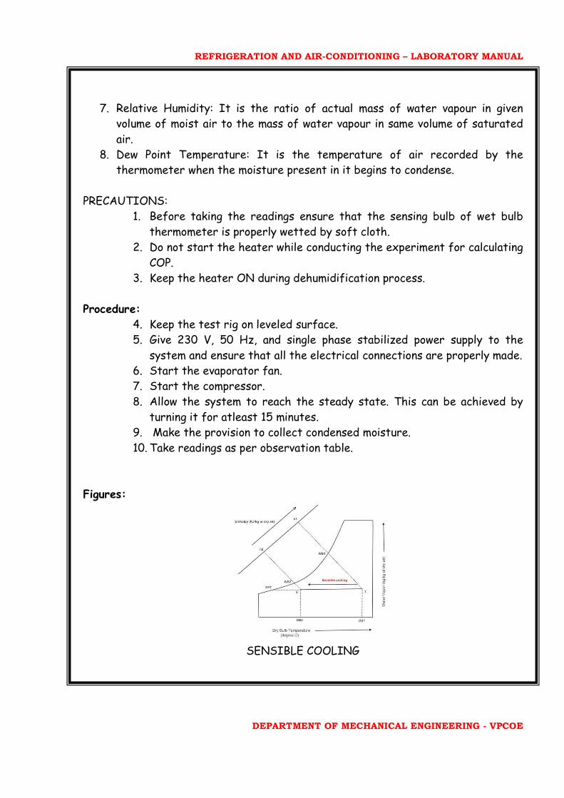
Figures:
SENSIBLE COOLING
REFRIGERATION AND AIR-CONDITIONING – LABORATORY MANUAL
DEPARTMENT OF MECHANICAL ENGINEERING - VPCOE
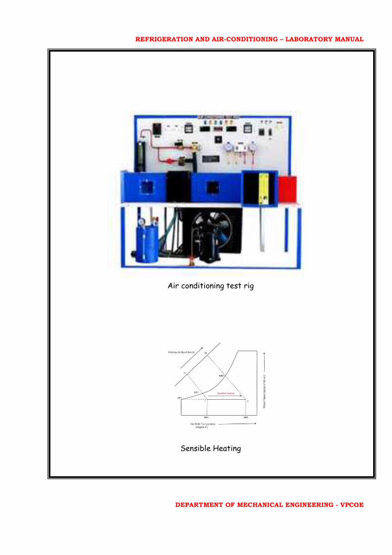
Air conditioning test rig
Sensible Heating
REFRIGERATION AND AIR-CONDITIONING – LABORATORY MANUAL
DEPARTMENT OF MECHANICAL ENGINEERING - VPCOE
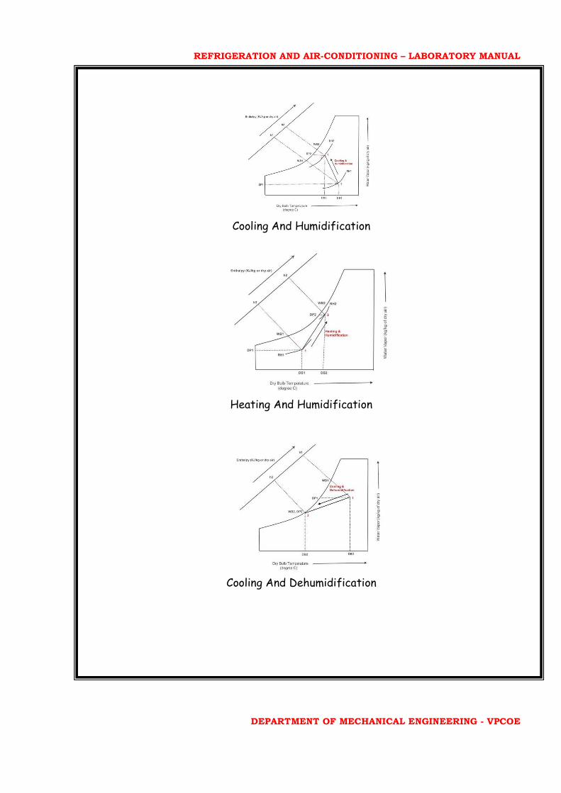
Cooling And Humidification
Heating And Humidification
Cooling And Dehumidification
REFRIGERATION AND AIR-CONDITIONING – LABORATORY MANUAL
DEPARTMENT OF MECHANICAL ENGINEERING - VPCOE
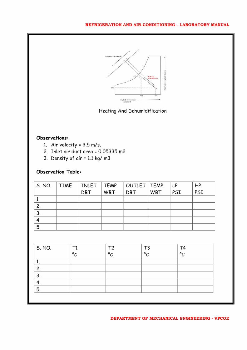
Heating And Dehumidification
Observations:
1. Air velocity = 3.5 m/s.
2. Inlet air duct area = 0.05335 m2
3. Density of air = 1.1 kg/ m3
Observation Table:
S. NO. TIME INLET
DBT
TEMP
WBT
OUTLET
DBT
TEMP
WBT
LP
PSI
HP
PSI
1
2.
3.
4
5.
S. NO. T1
°C
T2
°C
T3
°C
T4
°C
1.
2.
3.
4.
5.

REFRIGERATION AND AIR-CONDITIONING – LABORATORY MANUAL
DEPARTMENT OF MECHANICAL ENGINEERING - VPCOE
Energy Meter:
Where,
T1 = compressor outlet temperature
T2 = liquid line temperature
T3 = compressor inlet temperature
T4 = temperature after expansion
S.
NO
PROCES INLET
DBT
INLET
WBT
OUTLET
DBT
OUTLET
WBT
REMARKS
1. Heating Only heater ON
2. Cooling Only lamp ON
3. Humidification Humidification
4. Humidification and
Cooling
Humidification
and lamp ON
5. Heating and
Dehumidification
Humidification
and heater ON
6. Cooling and
Dehumidification
Dehumidification
and Lamp ON
CALCULATIONS:
m= Q*ρ
Now,
Inlet DBT = 92°F = (92-32)/1.8 °C = 33.5°C
Outlet DBT = 58°F = (58-32)/1.8 °C = 14.44°C
Refrigeration Effect = m. δh
From chart,
h1 =
h2 =
Refrigeration Effect =
Now work done by compressor = Final EMR – Initial EMR
REFRIGERATION AND AIR-CONDITIONING – LABORATORY MANUAL
DEPARTMENT OF MECHANICAL ENGINEERING - VPCOE
So COP (actual) = R.E/W.D
Thus,
W.D =
COP = R.E/W.D
P1 = Absolute suction pressure
= Patm + Pg
P2 = Absolute suction pressure
T1 = T2 = T3 = T4 =
By p-h chart,
h1 = kJ/kg
h2 = kJ/kg
h3 = h4 = kJ/kg
COP (theoretical) = (h1 – h4) / (h1 – h2)
Result:
1. Theoretical COP =
2. Actual COP =
REFRIGERATION AND AIR-CONDITIONING – LABORATORY MANUAL
DEPARTMENT OF MECHANICAL ENGINEERING - VPCOE
EXPERIMENT NO. 4
TITLE: VAPOUR ABSORPTION REFRIGERATION SYSTEM
Objective: Trial on vapour absorption refrigeration system (Electrolux
Refrigeration) to find out actual and theoretical COP.
Apparatus: Refrigeration test rig.
Theory:
Electrolux Refrigerator:
This type of refrigeration is usually used for domestic purposes only as it is complex
in the construction and working. This type of refrigerator was developed in 1925 by
Munters and Battzervan when they were studying at Royal Institute of Technology
At Stockholm for their undergraduate course. This type of refrigerator was known
as three fluid refrigeration system. The elimination of aqua pump from the
absorption system with the complete absence of moving parts and work input. The
main purpose of removing the pump was to make the machine noiseless. It uses
refrigerant as a solvent s and an inlet gas for inlet of the system. The inert gas is
continued to the lower side of system only by its system. It is possible to maintain
the uniform pressure throughout the system and after sometime permitting the
refrigerant to evaporator at low temperature corresponding to its partial pressure.
In the high pressure side system (generator and condenser), there exists only the
refrigerant which is subjected to total pressure of the system so that it is
condensed by using normal cooling water as air as it is done in other system.
In lower side of the system, the total pressure is sum of the partial pressure of
hydrogen which is used as an inert gas. The liquid ammonia which comes into the
evaporator as the partial pressure of ammonia is low.
The strong aqua ammonia solution is heated in generator by the application of
external heat source. The water vapour carried with ammonia vapour is removed in
separate form as shown in figure. Then the dry ammonia vapour is passed into the
condenser and it is condensed by using external cooling source. The liquid ammonia
flows under gravity in the evaporator and it evaporates. The mixture of hydrogen
and ammonia vapour is passed into the absorber and the weak solution from aqua
ammonia from the separator is allowed to follow into the absorber, through tray this
weak aqua ammonia solution comes into contact with hydrogen separated. This strong
solution is further passed to the generator and it completes the cycle.

REFRIGERATION AND AIR-CONDITIONING – LABORATORY MANUAL
DEPARTMENT OF MECHANICAL ENGINEERING - VPCOE
There is no pump to create the pressure differential between condenser and
evaporator or not an expansion valve.
The hydrogen returns to the evaporator having no affinity for the absorbent. The
hydrogen is held in this condition by the V tube due to small pressure difference in
the system. The solution is circulated through absorber and generated by thermal
action alone. The paths are so arranged that the liquid refrigerant flows through
evaporator by gravity, only care is to be taken to keep hydrogen isolated in the
proper part of the system otherwise pressure will be unbalanced and the machine
will stop.
Procedure:
1. Switch on the main supply.
2. Start the bulb inside the cabin.
3. Adjust current and the supply voltage.
4. Take the initial temperature reading.
5. Repeat the procedure after sometime.
6. Take readings until the steady state is reached.
7. When steady state is reached, take this reading for calculation and find the
theoretical and actual COP>
Figures:
VAPOUR ABSORPTION SYSTEM

REFRIGERATION AND AIR-CONDITIONING – LABORATORY MANUAL
DEPARTMENT OF MECHANICAL ENGINEERING - VPCOE
DOMESTIC TYPE ELECTROLUX REFRIGERATOR
Observation Table: Sr.
NO
TIME
TAKEN
WITH
OUT
LOAD
T1 T2 T3 T4 T5 T6 V (VOLTS)
I (AMPERE)
WATT
(V*I)
1.
2.
3.
4.
5.
Where,
T1= Temperature before generation
T2= Temperature after generation
T3= Temperature of evaporator
T4= Temperature of condenser
T5= Temperature of absorber
T6= Temperature of cabinet
REFRIGERATION AND AIR-CONDITIONING – LABORATORY MANUAL
DEPARTMENT OF MECHANICAL ENGINEERING - VPCOE
Calculations:
1. COP= T3(T2-T5))/T2(T5-T3)
2. COP= (V*I)/W
Result:
1. Theoretical COP =
2. Actual COP =