Refractories in the chemical industries - Bizuando...properties and behaviour of refractory...
15
Refractories in the chemical industries L. G. HUGGETT Imperial Chemical Industries Limited, Agricultural Division, Materials Group S~mmary Attention is drawn to the contrast be- tween the state of knowledge of the properties and behaviour of refractory materials in the wide variety of hostile environments to which they are sub- jetted and" the so far poorly developed state of refractories engineering. The chemical industry itself provides a con- siderable variety of environmental conditions, the effects of these have generally been well studied and the most important of them are discussed. In parts of the chemical industry, notably in hydrocarbon processing, the conditions for refractories are rather easy, however reliability is par- ticularly important and this combina- tion of circumstances makes it specially necessary to minimise deficiencies in design and construction. Materials must be chosen with generous safety margins in temperature capability and the refractory construction system, whether brick, monolithic or fibre, should be suitable not only for the operating conditions but also for the type of'equipment concerned and the construction circumstances. The ad- vantages of refractory concretes, for :xample, show themselves particularly tn lining reactors and other equipment of complex shape: ceramic fibres are an important and developing system: brickwork has the longest history of development. Whatever the system attention to detail is very important in ensuring a high reliability. In recent years several novel processes have been investigated based on the use of refrac- tory ceramic heat exchange materials. Some of these present very severe engineering design problems and it seems doubtful whether the demand will provide the incentive to solve them. Development of a basic refrac- tories engineering remains the most important need in this industry. Introdu=ion The technology of refractories is one of the most ancient and its develop- ment has been largely a history of continual response to the demands of increasingly more difficult high temperature processes. The success of this response and the understanding of the properties and behaviour of refractory materials has in recent years involved the most sophisticated studies in physical chemistry, experimental physics and other branches of science, yet it is not hard to understand why in the actual use of these materials, the basic engineering principles are only just being learned. Refractories engineering is still emerging from the limbo between the level of craft and knowledge based on trial-and-error experience and the status of a developed branch of engineering like civil engineering and others in the construction industries, well supported by experimental studies and with well- codified practices. It is a very difficult field to study and the need for greater knowledge of the engineering principles involved in the successful use of re- fractories has been obscured by the fact that in many processes the condi- tions are so severe that the life of refractory structures is limited by the durability of the materials. Classification of materials Refractories can be grouped by chemi- cal composition, by physical form, by temperature capability and by suit- ability for specialised industrial usage and between these classifications there are complex inter-relationships. Although some use is made of the more specialised compositions, the great bulk of refractory material of interest to the chemical and petro- chemical industries falls into the class of alumino-silicate refractories. Nearly the whole of this binary system is represented by commercially available products including pure alumina, pure mullite and a very wide range of pro- ducts made from clays, bauxite and other minerals. The silica end of the phase diagram (Fig. 1) is actually com- plex because of the various crystal forms of silica, but there is also a vitre- ous non-crystalline form, of growing importance and of interest in some chemical processes. As far as physical forms are con- cerned the principal distinction is between fired refractories and the so called monolithic refractories which can be moulded, rammed, sprayed or cast like concrete; the refractory concretes or castables are indeed a very important group. In the last decade the development of ceramic fibres, both glassy and crystalline, much helped by the unfortunate toxicity of asbestos, but of much wider appli- cation, has added quite new forms, 280 MATERIALS IN ENGINEERINGAPPLICATIONS. Vol. 1. September 1979
Transcript of Refractories in the chemical industries - Bizuando...properties and behaviour of refractory...
Refractories in the chemical industries
L. G. HUGGETT
Imperial Chemical Industries Limited, Agricultural Division, Materials Group
S~mmary Attention is drawn to the contrast be- tween the state of knowledge of the properties and behaviour of refractory materials in the wide variety of hostile environments to which they are sub- jetted and" the so far poorly developed state of refractories engineering. The chemical industry itself provides a con- siderable variety of environmental conditions, the effects of these have generally been well studied and the most important of them are discussed. In parts of the chemical industry, notably in hydrocarbon processing, the conditions for refractories are rather easy, however reliability is par- ticularly important and this combina- tion of circumstances makes it specially necessary to minimise deficiencies in design and construction. Materials must be chosen with generous safety margins in temperature capability and the refractory construction system, whether brick, monolithic or fibre, should be suitable not only for the operating conditions but also for the type of 'equipment concerned and the construction circumstances. The ad- vantages of refractory concretes, for :xample, show themselves particularly tn lining reactors and other equipment of complex shape: ceramic fibres are an important and developing system: brickwork has the longest history of development. Whatever the system attention to detail is very important in ensuring a high reliability. In recent years several novel processes have been investigated based on the use of refrac- tory ceramic heat exchange materials.
Some of these present very severe engineering design problems and it seems doubtful whether the demand will provide the incentive to solve them. Development of a basic refrac- tories engineering remains the most important need in this industry.
Introdu=ion The technology of refractories is one of the most ancient and its develop- ment has been largely a history of continual response to the demands of increasingly more difficult high temperature processes. The success of this response and the understanding of the properties and behaviour of refractory materials has in recent years involved the most sophisticated studies in physical chemistry, experimental physics and other branches of science, yet it is not hard to understand why in the actual use of these materials, the basic engineering principles are only just being learned.
Refractories engineering is still emerging from the limbo between the level of craft and knowledge based on trial-and-error experience and the status of a developed branch of engineering like civil engineering and others in the construction industries, well supported by experimental studies and with well- codified practices. It is a very difficult field to study and the need for greater knowledge of the engineering principles involved in the successful use of re- fractories has been obscured by the fact that in many processes the condi- tions are so severe that the life of
refractory structures is limited by the durability of the materials.
Classification of materials Refractories can be grouped by chemi- cal composition, by physical form, by temperature capability and by suit- ability for specialised industrial usage and between these classifications there are complex inter-relationships.
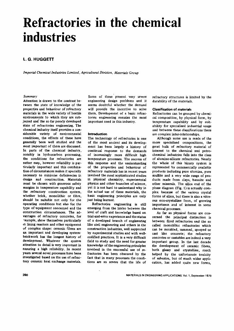
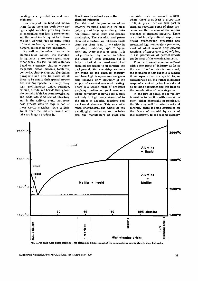
Although some use is made of the more specialised compositions, the great bulk of refractory material of interest to the chemical and petro- chemical industries falls into the class of alumino-silicate refractories. Nearly the whole of this binary system is represented by commercially available products including pure alumina, pure mullite and a very wide range of pro- ducts made from clays, bauxite and other minerals. The silica end of the phase diagram (Fig. 1) is actually com- plex because of the various crystal forms of silica, but there is also a vitre- ous non-crystalline form, of growing importance and of interest in some chemical processes.
As far as physical forms are con- cerned the principal distinction is between fired refractories and the so called monolithic refractories which can be moulded, rammed, sprayed or cast like concrete; the refractory concretes or castables are indeed a very important group. In the last decade the development of ceramic fibres, both glassy and crystalline, much helped by the unfortunate toxicity of asbestos, but of much wider appli- cation, has added quite new forms,
280 MATERIALS IN ENGINEERING APPLICATIONS. Vol. 1. September 1979
creating new possibilities and new problems.
For many of the fLred and mono- lithic forms there are both dense and lightweight varieties providing means of controlling heat loss to some extent and the use of insulating bricks to form the hot, working face of many kinds of heat enclosure, including process heaters, has become very important.
As well as the refractories in the alumina-silica system, the manufac- turing industry produces a great many other types: the less familiar materials based on magnesite, chrome, chrome- magnesite, zircon, zirconia, forsterite, cordierite, chrome-alumina, aluminium phosphate and now tin oxide are all there to be used if their special proper- ties are appropriate. Virtually every high melting-point oxide, sulphide, carbide, nitride and betide throughout the periodic table has been investigated and made into some sort of refractory and in the unlikely event that some new process were to require one of these exotic materials there is little doubt that the industry would not take too long to produce it.
Conditions for refractories in the chemical industries Two thirds of the pJ'oduction of re- fractory materials goes into the steel industry and large quantities go into non-ferrous metal, glass and cement production. The chemical and petro- chemical industries are relatively small users but there is no little variety in operating conditions, types of equip- ment and every aspect of usage. It is not profitable to try too hard to define the limits of these industries but it helps to look at the broad context of chemical processing to understand the background. Wet chemistry accounts for much of the chemical industry and here high temperatures are gene- rally involved only indirectly in the supply of external means of heating. There is a second range of processes involving molten or solid reactants where refractory materials are subject not only to high temperatures but to the effect of chemical reactions and mechanical abrasion. This very wide range encompasses the whole of the metallurgical industries and includes also the manufacture of glass and
materials such as cement clinker, where there is at least a proportion of liquid phase that can take part in chemical reaction: some of these pro- cesses are the concern of the various branches of chemical industry. There is a third broadly defined range, com- prising hydrocarbon processing and associated high temperature processes, most of which involve only gaseous reactions, of importance in off refining, in the production of petrochemicals and in parts of the chemical industry.
Thus there is much common interest with other parts of industry as far as the use of refractories is concerned; the intention in this paper is to discuss those aspects that are special to, or characteristic of, this rather ill-clef'reed range of chemical, petrochemical and oil-refining operations and this leads to the consideration of two categories.
In the first of these, the refractory is sensitive to reaction with its environ- ment, either chemically or physically, the life may well be rather short and generally there is some constraint on the choice of material by virtue of this reactivity. In the second category
2 0 0 0 ° C
1800°C
1600oc
Silica +
liquid
Liquid
Mullite + liquid
Alumina + liquid
Alumina +
Mullite
2 0 0 0 o c
1 8 0 0 o c
1 6 0 0 o c
1400°C 20 40 60 80% alumina I | I I
® .~ 4=* • m U .~ = .=
.= ~ o . o a.. 0
O. " i .~ ..~ u) High-alumina bricks -~
Fig. I. Alumina-silica phase diagram. This diagram represents most of the compositions used in the chemical industries.
1 4 0 0 o c
MATERIALS IN ENGINEERING APPLICATIONS. Vol. 1. September 1979 2 8 1
refractories operate mainly in a clean environment and the condit ions are very easy, ye t paradoxically it is in this context that one can see certain prob- lems that should be receiving increasing a t tent ion in the future and perhaps even forming the main focus of atten- tion. This situation is particularly characteristic of hydrocarbon processes based on gas and light oil fraction feed- stocks and . the closely related high- temperature hydrogen and nitrogen chemistry. All these are normally operated on a large scale and on a con- t inuous basis and this, together with the relative absence of effects due to chemical reactions and mechanical abrasion, produces condit ions that are rather different from those in many other industries, condit ions which lead to a design approach that evidently needs to be somewhat different. This approach is one in which it becomes necessary to examine the engineering design detail at least as carefully as the choice of refractory materials. When these materials are not subjected to ext reme condit ions they are capable of very long life if they are not overheated and since plant shutdown is very ex- pensive and unplanned shutdowns are particul~irly undesirable in cont inuous process operat ion there is a conside- rable incentive to obtain refractory linings that will indeed last many years.
Such long life is only possible of course provided that the materials are used in a proper manner but with sensible selection of material and proper a t tent ion to engineering design detail, there is in most cases no reason why the life should not be ten years or more. This is something that the refractories industry has in the past not been accustomed to and practices have become accepted whose faults have been obscured by the relatively short life of the materials, but it is becoming necessary to adopt better and more careful design and construc- tion and this can only be to the bene- fit, not only of the chemical industry, but o f all users o f refractories.
Reactive environments Reactivity is a convenient term under which to group the variety of responses to the very damaging condit ions that refractories may suffer, which include the corrosive slagging processes and other chemical effects but also a num- ber of physical effects and some that arc a combinat ion. Some of the more serious maladies w i th specially charac- teristic symptoms have descriptive
names like 'cobble-stoning' , 'rat- holing' , 'slabbing' and so on.
Physical effects Purely physical effects include spalling due to thermal shock. Standard tests have been produced to measure the susceptibility of refractories to thermal shock, but no really satisfactory methods are available, largely because of the difficulty in reproducing the condit ions of practical service. In one investigation (1) a large number of proprietary bricks and refractory con- cretes, all of the alumino-silicate type with alumina content in the range 50-65%, were examined for their suitability as materials for lining drier furnaces used in fertiliser product ion and for the burner quarls used in these furnaces. Typically these are hori- zontal cylinders, 2 to 4 m diameter, fired from one end and the gases pro- duced in the combust ion chamber are diluted with secondary air to produce gases at 400°C or so, suitable for drying in rotary driers for example. Intermit- tent plant operat ion and use of heavy fuel-oil for firing produce severe thermal shock condit ions and refrac- tory lining life of only two months was the incentive for the investigation.
It has long been accepted that the British Standard method of test for thermal shock resistance based on successive heating and air-cooling is not severe enough to be very discrimi- nating. A water-quenching between each heating cycle is severe enough and test condit ions could be chosen to cause failure after only one cycle with the poorer materials whereas the best were capable of withstanding ten or more. Plant trials correlated unusu- ally well with the results of the labora- tory tests and in service the better materials lasted at least a year.
Two striking facts emerged from this investigation, first the remarkably wide range in sensitivity in materials of very similar composi t ion and range of application, second the general superiority of refractory concretes. The water-quanch test was later the subject of a national co-operative study and in a modified form was adopted as a British Standard (BS 1902 Part C ) b u t by increasing the heating temperature , was made more severe. As a result the test in its present form will not dis- criminate as satisfactorily as the origi- nal, perhaps fortunately chosen, condi- tions and this illustrates the difficulty in designing such tests.
Abrasion resistance is an even more difficult proper ty to define and
measure and if a test is to be useful it must a t tempt to reproduce as nearly as possible the condit ions of service, a requirement that is usually ex t remely difficult to meet.
Damage by slagging No less difficult is the testing of resis- tance to slags and other mol ten sub- stances and many tests have been de- vised to incorporate not only the e lement of chemical corrosion, but the effects also of erosion where rela- tive movement over the surface of the refractory accelerates the failure.
As with metals this combinat ion of corrosion and removal of corrosion product by erosion can be very damag- ing; under adverse circumstances it can be devastating and inches of material can be removed in a mat ter of hours. The product ion of sulphuric acid from anhydri te (calcium sulphate) in rotary kilns, no longer used in the UK because of a decrease in the price of sulphur, but still in use elsewhere in Europe, is very similar to the convent ional manu- facture of cement clinker but with somewhat greater problems of feed and atmosphere control . The calcium sulphate is reduced to SO2 and subse- quent ly converted catalytically to SO 3 and the lime goes to make cement clinker. The alumino-silicate refrac- tories used thir ty years ago were re- placed by the less reactive basic refrac- tories, mainly magnesite-chrome bricks. The life of these refractories, varying from a few months to perhaps two years, depends typically on a number of factors. These include the degree of process control , the mechanical stress on the refractory lining due to distor- t ion in the kiln shell as it rotates, the tightness with which the lining is in- stalled and the readiness with which a coating of clinker is built up on the lining (2, 3). While properties of the refractory such as resistance to thermal shock and hot-strength are relevant the factors that have nothing to do with the propert ies of the refractory have a similar level of importance.
Best practice, as in convent ional cement manufacture, is based on the establishment of a coating in the burn- ing zone consisting of a layer of chilled clinker that adheres to the refractory and provides a protective working hot-face that prolongs the life of the refractory brick. The stability of this layer depends on many factors and if too much sulphate or sulphide appear in this hot zone a fusion results that can erode the coating and the lining very rapidly. This dependence of
282 MATERIALS IN ENGINEERING APPLICATIONS. Vol 1. September 1979
the life of the refractory on a complex set of condit ions, chemical and mech- anical, that are particular to the process concerned, is c o m m o n in difficult high- temperature processes.
The sodium sulphide revolver, ope- rating at around 1000°C is something like a short rotary kiln but rocks rather than rotating cont inuously. It is used in a batch process and the lining is subjected alternately to thermal shock from each cold charge and erosion from the mol ten contents during the heating cycle. An application of first principles would suggest at least one of the higher alumina firebricks with good resistance to thermal shock: in fact what was found to be very satis- factory was a dense highly vitrified red shale engineering brick. This unex- pected observation teaches a number of lessons. The most impor tant is that low porosity and permeabil i ty are highly beneficial in conferring resis- tance to melt corrosion. Secondly, damage by thermal shock is in practice a most complex thing and failure purely by thermal stress set up by rapid temperature changes is very often complicated by other effects; indeed 'failure ' itself needs defini t ion and in a given practical si tuation may not be anything like the ' fai lure ' that is de- tectable in a laboratory test. Cracks are detectable in bricks subjected to thermal strain long before any obvious external signs of damage. Lastly of course, one must consider economic factors: in this particular example regular repair or replacement of a cheap lining was readily acceptable as pa r t ' o f the product ion routine.
Incinerators are likely to become increasingly impor tant : this has re- ceived general notice in the context of domest ic refuse disposal but it is also true in the chemical industry, for example in the product ion of nylon chemicals, where disposal of waste by dumping will become increasingly difficult or uneconomic. Where waste products contain catalyst residues there may be an incentive to recover these residues. Some liquid wastes contain considerable amounts of water and where this is the case there are special problems. Combust ion is diffi- cult and splashing of hot refractory with cold liquid is liable to shorten the life o f the incinerator lining. The spalling condit ions in incinerators are of ten specially severe and the con- clusions drawn from the investigations previously ment ioned, of materials for drier furnaces, have been found rele- vant to incinerators also.
Solid phase reactivity Lime product ion provides an interest- ing example of a mode of failure which can be due to the iase of refractory that is, in a sense, too good. This occurs where the refractory takes part in chemical reaction at high tempera- ture where the reactants and reaction products are all in the solid phase, somet imes gas and solid phase, but not including liquid. Where such a reaction involves a large change in volume disruptive effects may occur. Disruptive effects due to chemical reactions producing marked increase in volume of the reacting material are well-known where there is no high temperature and one of the most wide- spread is the case of sulphate-expansion in Portland cement concrete and brick- work mortar .
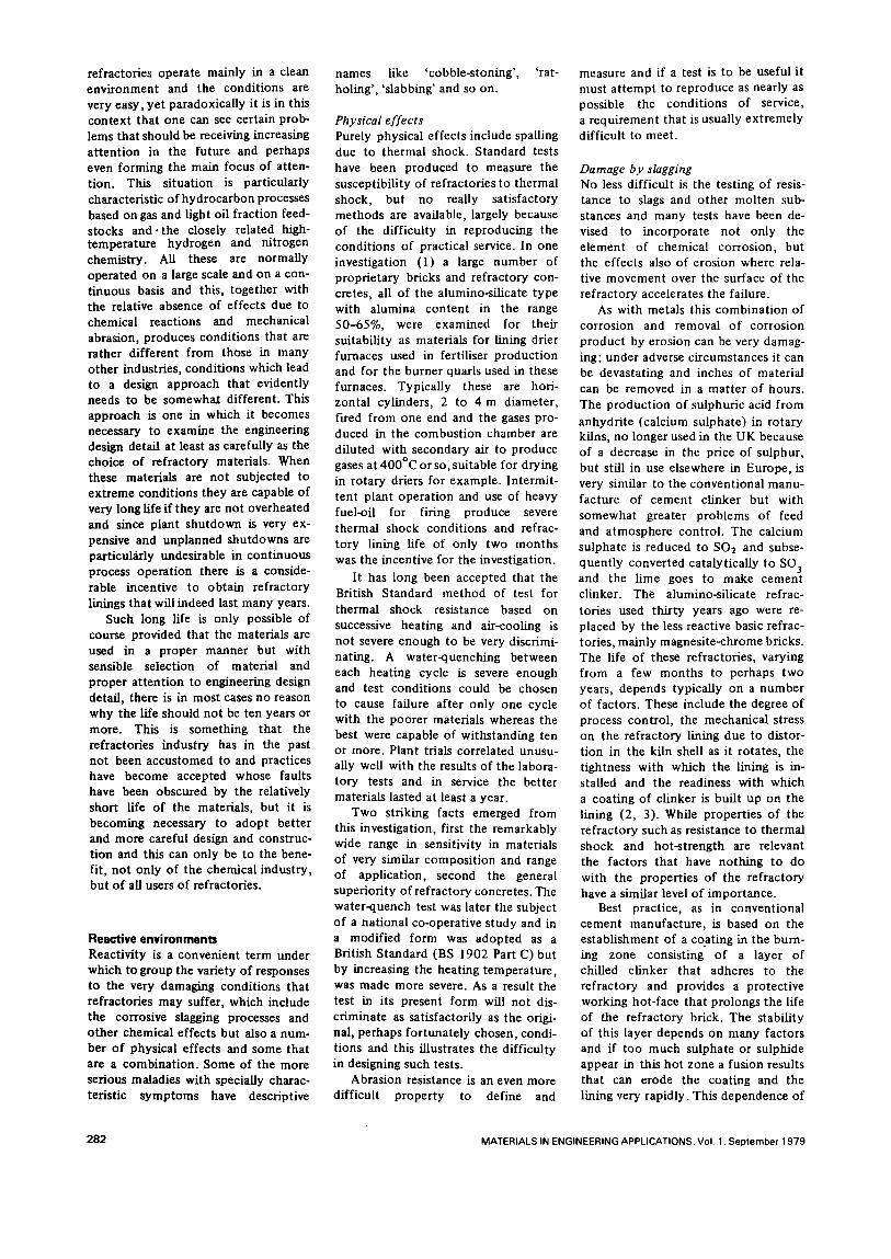
Volatile alkali oxides - sodium oxide is the most important in this con tex t - are produced when lime is calcined and they react with alumino- silicate refractories under favourable condi t ions to produce new solid phases and since this react ion can be accompanied by an increase in volume, disruption of the refractory occurs (Fig. 2), usually near to the hot face, and the surface of the brick flakes off. Paradoxically the use of refractory that is inferior in the usual sense, that it will not withstand such a high temperature , may solve the problem. A liquid rather than a solid reaction product is formed which does not give rise to the volume change and if the liquid is not too fluid or too great in amount , does not cause rapid failure.
A classic high temperature example is well known in the technology of basic refractories and is referred to as iron oxide 'burst ing ' ; it occurs when iron oxide is heated in contact with certain bricks based on chrome ore and magnesite (Fig. 2). The effect is a result of the format ion of a spinel, a compound of a bivalent and a triva- lent oxide, of a characteristic crystal form and c o m m o n in basic refractory systems. The forms involved are mainly ferrites and chromites and have a variety of composi t ions based mainly on MgO, FeO, Fe2Oa and Cr203 with a characteristic tendency for very ready substi tut ion between the various cations involved. Investigations (5) showed that many such spinel-forming systems exhibit this expansion ten- dency, but bursting expansion does not always occur when spinels are formed. It is not dependent only on density differences but also on a phenomenon first observed in metal
systems where some pairs of metals in contac t exhibit , when heated, the Kirkendall effect . This is an effect in which unequal rates o f diffusion across the interface between the two metals give rise to the appearance of holes in the crystal lattice, which can coalesce into pores. This effect o f unequal diffusion rates, the reverse o f the sintering process, occurs in many com- binations of spinels and related systems.
The same effect can occur in high- aluminia refractories in contac t with heavy fuel oil ash. The deve lopment o f porosity has been clearly shown in the metal systems but, a l though the unequal diffusion has been demonst ra ted in refractory systems, these materials are already porous and highly hetero- geneous and the format ion of additional porosi ty is harder to discover. It is probably much more widespread than is generally recognised and has been shown to occur in the high- temperature gasification of heavy fuel-oil to produce hydrogen (1).
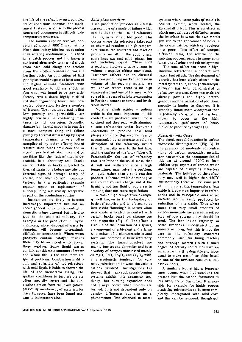
Reactivity with Gases The classic gas-solid react ion is ' carbon monoxide disintegrat ion ' (Fig. 3). In the presence of modera te concentra- t ions of carbon monoxide , metallic iron can catalyse the decomposi t ion of this gas at around 450°C to form whisker-type crystals o f carbon which are capable of disrupting refractory materials. The hot-face of the refrac- tory may well be higher than 450°C but normally there will be some part of the lining at this temperature . I ron oxide is a c o m m o n impuri ty in refrac- tories and in susceptible ones active metallic iron is easily produced by reduct ion of the oxide. Thus where more than very small amounts of carbon monoxide are present a refrac- tory of low susceptibility should be used. The iron oxide impur i ty in some firebricks is combined in an unreactive form, but this is not the case in the refractory concretes c o m m o n l y used for lining reactors
and al though materials with a small degree o f activity somet imes have an acceptable life it is desirable and more usual to make use of castables based on one o f the low-iron calcium alumi- nate cements.
A similar effect at higher tempera- tures occurs when hydrocarbons are present but the carbon format ion is less likely to be disruptive. It is pos- sible for example for highly porous insulating refractories to become com- pletely impregnated with solid coke and this can be removed, though not
MATERIALS IN ENGINEERING APPLICATIONS. Vet 1. September 1979 283
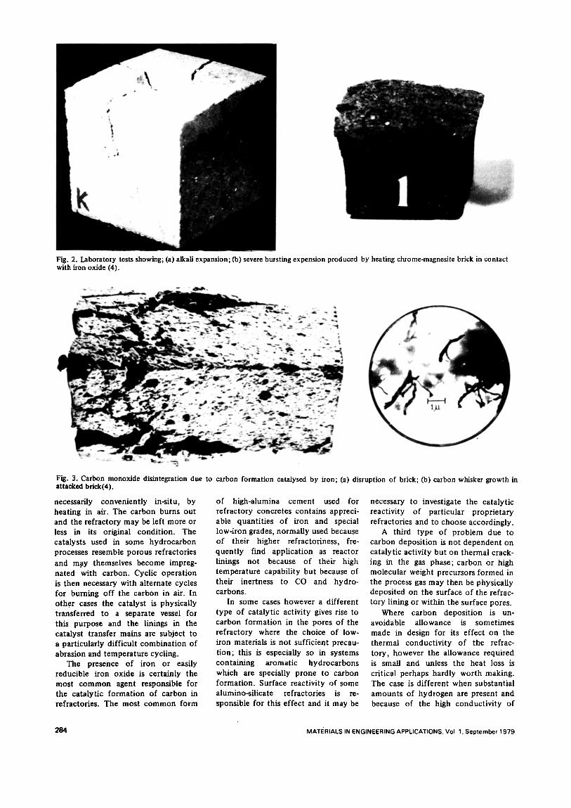
Fig. 2. Laboratory tests showing; (a) alkali expansion; Co) severe bursting expension produced by heating chrome-magnesite brick in contact with iron oxide (4).
Fig. 3. Carbon monoxide disintegration due to attacked brick(4).
necessarily conveniently in-situ, by heating in air. The carbon burns out and the refractory may be left more or less in its original condition. The catalysts used in some hydrocarbon processes resemble porous refractories
and may themselves become impreg- nated with carbon. Cyclic operation is then necessary with alternate cycles for burning off the carbon in air. In othor cases the catalyst is physicaUy transferred to a separate vessel for this purpose and the linings in the catalyst transfer mains are subject to a particularly difficult combination of abrasion and temperature cycling.
The presence of iron or easily reducible iron oxide is certainly the most common agent responsible for the catalytic formation of carbon in refractories. The most common form
carbon formation catalysed by iron; (a) disruption of brick; Co) carbon whisker growth in
of high-alumina cement used for refractory concretes contains appreci- able quantities of iron and special low-iron grades, normally used because of their higher refractoriness, fre- quently find application as reactor linings not because of their high temperature capability but because of their inertness to CO and hydro- carbons.
In some cases however a different type of catalytic activity gives rise to carbon formation in the pores of the refractory where the choice of low- iron materials is not sufficient precau- tion; this is especially so in systems containing aromatic hydrocarbons which are specially prone to carbon formation. Surface reactivity of some alumino-silicate refractories is re- sponsible for this effect and it may be
necessary to investigate the catalytic reactivity of particular proprietary refractories and to choose accordingly.
A third type of problem due to carbon deposition is not dependent on catalytic activity but on thermal crack- ing in the gas phase; carbon or high molecular weight precursors formed in the process gas may then be physically deposited on the surface of the refrac- tory lining or within the surface pores.
Where carbon deposition is un- avoidable allowance is sometimes made in design for its effect on the thermal conductivity of the refrac- tory, however the allowance required is small and unless the heat loss is critical perhaps hardly worth making. The case is different when substantial amounts of hydrogen are present and because of the high conductivity of
284 MATERIALS IN ENGINEERING APPLICATIONS. Vol 1. September 1979
this gas it is necessary to make allow- ance. Several models have been pro- posed to represent the flow of heat through porous media and depending on the model chosen the effect of the presence of hydrogen in the pores can be allowed for in the expression for thermal conductivity. However, it is not worth going to the trouble of making a special study to see which model is most suited to a particular refractory or to use a complex expres- sion to represent conductivity. It is sufficient to calculate the approximate conductivity of the gas mixture con- cerned, to consider the pore volume in the refractory as making a zero contri- bution to the overall conductivity in air and simply to add the contribution made by the hydrogen-containing gas. Thermal conductivities, heat flow calculations and heat balances are rarely so accurate as to warrant more. Neither are estimates of the working temperatures of materials so critical or so independent of other difficult-to- estimate design factors.
The powerful reducing effect of hydrogen must of course be reckoned with. The effect of FeO on the melting behaviour of alumino-silicates is very different from the effect of Fe203; with only 1 or 2% of iron the effect of the reduction on the refractoriness of the material may be startling and even with nominally iron-free materials the high temperature shrinkage can be markedly affected. The effect can be found even in heater atmospheres that are nominally oxidising, and this is a problem that is discussed later. How- ever, in reactors hydrogen may be a major constituent in the process gas. If the temperature is high enough the silica in alumino-silicate refractories can itself be reduced; volatile silicon monoxide is distilled off and either reoxidises or decomposes into silicon and silica, condensing downstream. This effect has been known for many years in metallurgical processes, but the extent to which it occurs falls off rapidly below about 1300°C because the temperature coefficient of the equilibrium constant is quite high.
Volatile silica can however be a serious problem in certain reactors in ammonia plants: these are the second- ary reformers in which residual me- thane remaining from the reforming of hydrocarbon to give hydrogen is catalytically removed. The process gas contains a high partial pressure (8-12 bar) of steam but the temperature is only about lO00°C, a temperature too low for silica to be reduced by hydro-
gen to a significant extent. If silica- bearing refractories or catalyst are present silica is removed however, not by formation of silicon monoxide but by solution of silica in the steam (6). This volatilisation is independent of the presence of hydrogen and it can leave the refractory porous and mech- anically weak but the most immediate adverse effect is fouling of the tubes in the boilers used for gas-cooling and heat-recovery.
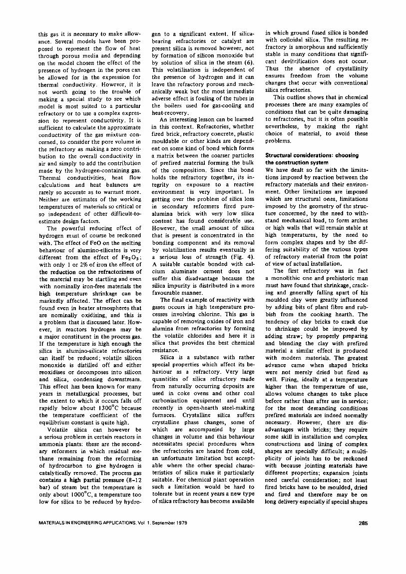
An interesting lesson can be learned in this context. Refractories, whether fired brick, refractory concrete, plastic mouldable or other kinds are depend- ent on some kind of bond which forms a matrix between the coarser particles of prefired material forming the bulk of the composition. Since this bond holds the refractory together, its in- tegrity on exposure to a reactive environment is very important. In getting over the problem of silica loss in secondary reformers fired pure- alumina brick with very low silica content has found considerable use. However, the small amount of silica that is present is concentrated in the bonding component and its removal by volatilisation results eventually in a serious loss of strength (Fig. 4). A suitable castable bonded with cal- cium aluminate cement does not suffer this disadvantage because the silica impurity is distributed in a more favourable manner.
The final example of reactivity with gases occurs in high temperature pro- cesses involving chlorine. This gas is capable of removing oxides of iron and alumina from refractories by forming the volatile chlorides and here it is silica that provides the best chemical resistance.
Silica is a substance with rather special properties which affect its be- haviour as a refractory. Very large quantities of silica refractory made from naturally occurring deposits are used in coke ovens and other coal carbonisation equipment and until recently in open-hearth steel-making furnaces. Crystalline silica suffers crystalline phase changes, some of which are accompanied by large changes in volume and this behaviour necessitates special procedures when the refractories are heated from cold, an unfortunate limitation but accept- able where the other special charac- teristics of silica make it particularly suitable. For chemical plant operation such a limitation would be hard to tolerate but in recent years a new type of silica refractory has become available
in which ground fused silica is bonded with colloidal silica. The resulting re- fractory is amorphous and sufficiently stable in many conditions that signifi- cant devitrification does not occur. Thus the absence of crystallinity ensures freedom from the volume changes that occur with conventional silica refractories.
This outline shows that in chemical processes there are many examples of conditions that can be quite damaging to refractories, but it is often possible nevertheless, by making the right choice of material, to avoid these problems.
Structural considerations: choosing the construction system We have dealt so far with the limita- tions imposed by reaction between the refractory materials and their environ- ment. Other limitations are imposed which are structural ones, limitations imposed by the geometry of the struc- ture concerned, by the need to with- stand mechanical load, to form arches or high walls that will remain stable at high temperatures, by the need to form complex shapes and by the dif- fering suitability of the various types of refractory material from the point of view of actual installation.
The first refractory was in fact a monolithic one and prehistoric man must have found that shrinkage, crack- ing and generally falling apart of his moulded clay were greatly influenced by adding bits of plant fibre and rub- bish from the cooking hearth. The tendency of clay bricks to crack due to shrinkage could be improved by adding straw; by properly preparing and blending the clay with prefired material a similar effect is produced with modern materials. The greatest advance came when shaped bricks were not merely dried but fired as well. Firing, ideally at a temperature higher' than the temperature of use, allows volume changes to take place before rather than after use in service; for the most demanding conditions prefired materials are indeed normally necessary. However, there are dis- advantages with bricks; they require some skill in installation and complex constructions and lining of complex shapes are specially difficult; a multi- plicity of joints has to be reckoned with because jointing materials have different properties; expansion joints need careful consideration; not least fired bricks have to be moulded, dried and fired and therefore may be on long delivery especially if special shapes
MATERIALS IN ENGINEERING APPLICATIONS. Vol. 1. September 1979 285
are required. Monolithic refractories are unfired
and are normally unshaped, being installed in-situ, although refractory concretes are often precast before installation. The main advantages with monoli thic refractories are the greater ease with which complex constructions can be made, the absence of joints and the immediate availability. The type of skill that the bricklayer has is not necessary and this fact is of course well advertised; unfor tunate ly skill and care are often confused and if one thing is vital to success with monol i thic refrac- tories, it is the care to ensure that installation is properly done with due at tent ion to the important steps in the procedures.
Plastic mouldable refractories are not commonly used in chemical pro- cess plants, but refractory concretes of both the dense kind and the lightweight insulating kind are very important in all types of equipment . Castables made from a variety of lightweight aggregates are very widely used to line equipment such as heaters, ducting and flues operating at moderate temperatures. The low density confers low conduc- tivity roughly in linear proport ion to density but at the expense of strength. Great strength is of ten not necessary if all that is required is self-support of the refractory lining, but is neverthe- less not a bad thing to have to mini- mise mechanical damage during main- tenance or especially during the assembly of the prefabricated units that are nowadays common. There is surely scope for much further improve- ment in this type of refractory both in extending the range of temperature for which they are suitable and in im- proving the mechanical properties for example with such remarkable materi- als as exfoliated vermiculite. The chal- lenge in recent years from those other remarkable materials, the ceramic fibres, also rather weak mechanically, should not go unanswered.
The dense castables are specially suitabte for burner quarls, which suffer thermal strain and shock in varying degrees. For reasons that are not particularly clear, but perhaps have to d o with what might be called textural differences, castables are better than many fired refractories in this respect as has already been ment ioned, and since the specially shaped quarks are so conveniently made from castables they have found much use in this application.
The product ion o f precast shapes in these concretes is an important and
growing industry because of their versatility and convenience and very large shapes can if necessary be made that would be quite impossible in fired refractory. Precasting takes advantage also of the greatly improved quality that is possible when the manufacturing condit ions are right, with mixes of low water /cement ratio, with vibration to ensure good consolidation and with proper curing, therefore proper hydra- tion of the cement.
ln-situ the condit ions are not always right. Too much water, poor consolida- tion, segregation and poor hydrat ion due to inadequate curing are common faults which lead to low strength, high shrinkage and short life. A very useful and well-known technique for applying these materials is gunning, usually dry gunning, in which the opera tor who manipulates the gun nozzle controls the amount of water, controll ing it so as to avoid the two extremes where, if too dry, the concrete is poorly consoli- dated and there is too much rebound loss, and if too wet, it slumps. With a properly designed anchoring system, concrete may satisfactorily be applied overhead or in any other position on surfaces of any shape. If proper control is not exercised by the operator the results can be very bad.
This is the weakness of monoli thic refractories, that they can be and often are misused so badly either from carelessness or ignorance.
The use of ceramic fibres needs rather special consideration, partly be- cause they are still quite new and their range of use is not yet well defined, al though some uses are becoming established, and partly because new products, new forms and new methods of construct ion are being developed.
Choice of the type of construct ion, whether brick, monoli thic or fibre and the method of installation is only one aspect of design. To return to the opening theme of this essay, we may note the contrast between, on the one hand, the remarkable developments in formulat ion and product ion tech- nology by the manufacturers of these materials and the scientific studies into their behaviour and limitations by the interested research organisations and on the o ther hand the poorly developed technology of construct ion techniques and particularly of design. There are yet for example no codes of practice dealing with the actual installa- tion of refractory structures.
To examine this further it is neces- sary first to describe some of the equip- ment used in hydrocarbon processing,
much of which falls reasonably into the clean envi ronment category.
Hydrocarbon processing equipment The process equipment in which re- fractory materials are used is generally of two kinds, namely heaters and reactors. In the most c o m m o n form of heater the feed-stock is fed into tubes to be distilled, vaporised, reformed, etc., the necessary heat being developed by combust ion within the heater and absorbed by the tubes ei ther by radia- tion in the hot ter part or by convect ion from the cooler gases before they leave to go into the flue system which itself may be a large and necessary part of the construct ion. The refractory is subject only to contact with products of combust ion of the fuel. In reactors, the o ther major classification of equipment , the refractory is in contact with gaseous process fluid. No external heat is added although the required reaction may be dependent on combus- tion or o ther exothermic reaction be- tween the reactants and it will fre- quent ly be dependent on a catalyst. Associated with reactors are the gas transfer mains and boilers used to recover heat and reduce the tempera- ture of the reaction products to a level suitable for subsequent processing.
There are some reaction processes in which it is necessary to put heat into the reaction, but where for various reasons, for example if the tempera- ture is too high, it is not possible to use metal tubes. Regenerative heating or moving beds of ceramic heat-transfer media can be adopted and this type of reactor includes the pebble heater and fluidised bed reactors. In addit ion to the mechanical abrasion effects where movement of the heat transfer medium is involved, thermal shock is a major feature and the material in moving beds is itself subject to very severe temperature changes.
The type of equipment that can be included under the heading of process heaters falls into several categories, roughly as follows:
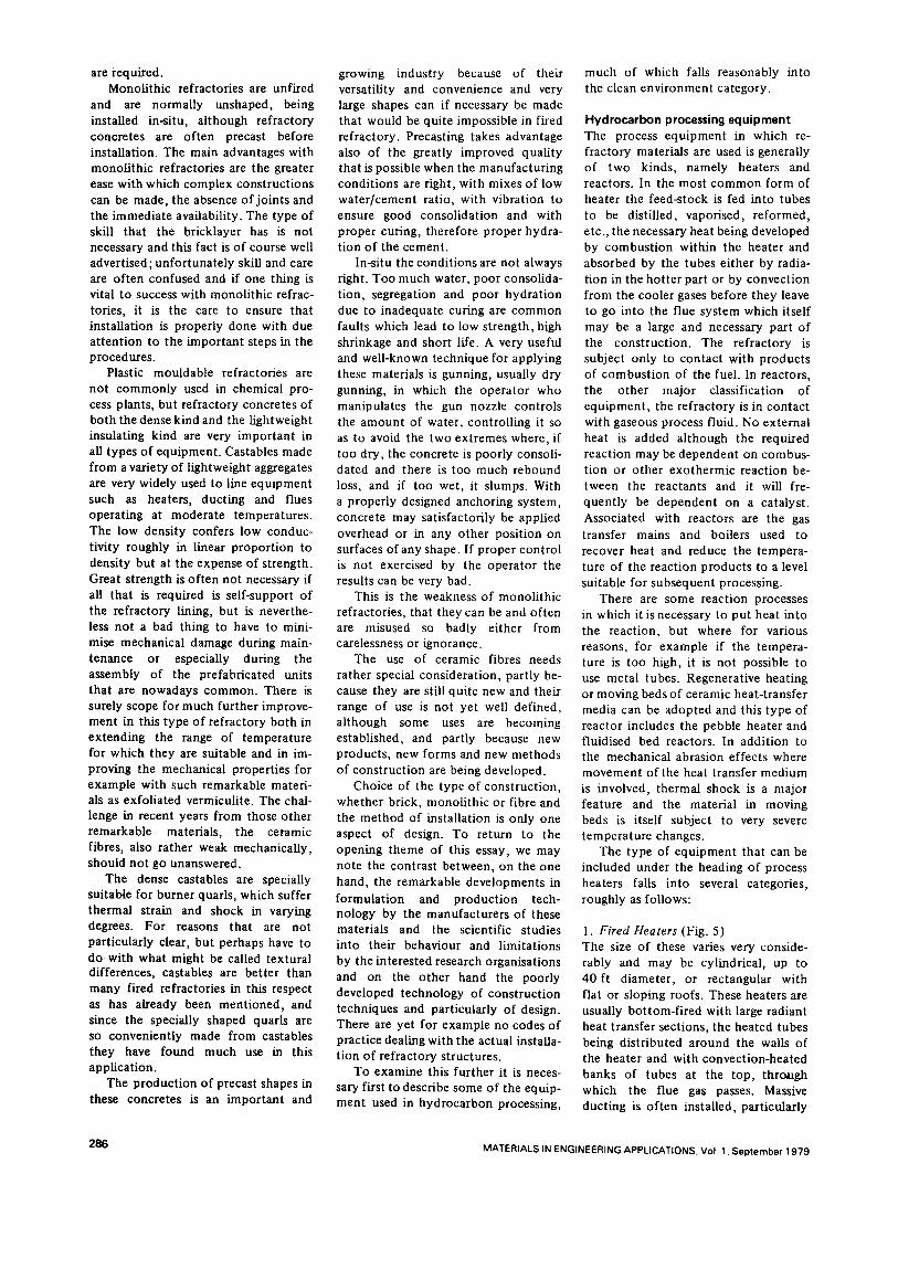
1. Fired Heaters (Fig. 5) The size of these varies very conside- rably and may be cylindrical, up to 40 ft diameter , or rectangular with flat or sloping roofs. These heaters are usually bot tom-fi red with large radiant heat transfer sections, the heated tubes being distributed around the walls of the heater and with convect ion-heated banks of tubes at the top, through which the flue gas passes. Massive ducting is of ten installed, particularly
286 MATERIALS IN ENGINEERING APPLICATIONS. Vol. 1. September 1979
• " s
• ' "~ ~;~ "'~'=~,~ t~ ~ ¢11 ." " f
Fig. 4. (a) Structure of alumina brick showing large grains and siliceous bonding material in between.
(b) Part of the same brick, exposed to process gas containing steam, showing loss of bonding material.
(c) Darker parts of large grains in alumino-silieate tastable show loss of silica.
where several heaters feed flue gas into a c o m m o n stack. Package boilers are of ten used and these are a particular example of fired heater.
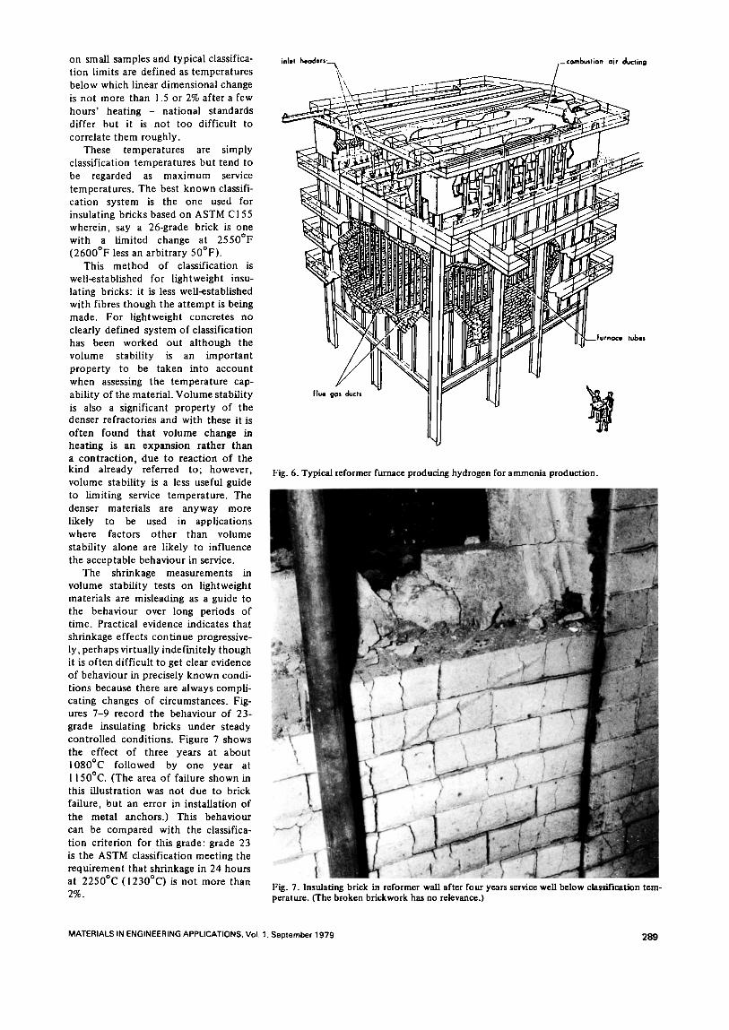
2. Reformer Furnaces (Fig. 6) These are usually rectangular boxes, generally top-fired somet imes fired f rom the side walls, in which the pro- cess fluid is reacted in vertical tubes. They are designed, typically, to pro- duce hydrogen for ammonia or methanol product ion and for o ther purposes.
3. Ethylene Crackers Cracker furnaces are also rectangular with mult i -burner side-firing and of ten addit ional upward-firing burners.
These applications have been listed roughly in the order of increasing temperature . Most of the tubular heaters used in oil refining and the petrochemicals industry are operated at relatively modest temperatures compared with many o ther refractory applications and flue-gas temperatures are frequent ly no more than 1000°C. In the radiant sections of the heaters the refractory linings behind the radiant tubes, which are close to the walls, is clearly at some level of temperature below that of the gas in the interior and it may be difficult to est imate exact ly what this level is: it is unlikely to exceed about 800°C, a temperature within the capability of practically any refractory insulating material. Low temperature-rated insu- lating concretes have been widely used for these applications but it is now becoming much more c o m m o n to use ceramic fibres.
After passing through the convec- tion tube bundles the flue gas is nor- maUy at a relatively low temperature and linings in ducting are usually not required to withstand especially high temperatures, so that insulating con- cretes and fibres are used here also. A case somet imes exists for providing more than the degree of refractoriness that might otherwise be expected in order to cope with the possibility of failure in the tube bundles. I f this occurs it can lead to a major leakage t~f f lammable gas from the process stream that passes through the tubes themselves into the flue gas; this can then burn in the excess air normally present producing higher temperatures than normal. Even so, it is unlikely that the temperature would be much higher than 1100-1200°C.
Reformer furnaces operate at
MATERIALS IN ENGINEERING APPLICATIONS. Vol. 1. September 1979 287
m
Fig. 5. Typical fired heaters (7).
around I I00°C and cracker furnaces may be hotter , locally as high as 1200-1300°C.
In recent years the standard method of lining reformer or similar furnaces has been with about 6 inches of insu- lating brick backed with insulating slab of calcium silicate or mineral wool. With the increasing pressure to mini- raise heat loss there has been a move from the level of 1000-1200W/m 2 that was normal ten to fifteen years ago to little more than half this value today. This means using linings of greater thermal resistance, either thick- er or with materials of lower thermal conductivi ty and this factor is clearly one that encourages the choice of ceramic fibre linings.
It can be seen that normally it is unnecessary to use highly refractory material, al though, as always, there are special situations where untypically high temperatures occur, where there is uncertainty, or where some other circumstance may dictate the intro-
/ \
/
j D e e e <
I
duct ion of some kind of safety margin. Burner quarlsare a case in point where, while normally highly refractory mate- rials are not used for them in this type of equipment , it is not unusual to choose a material with a nominal rating of 1600°C or more even though this temperature is rather unlikely to be reached. Refractory concretes are especially suitable for these small burner quarls.
A variety o f chemical processes involving reactions on hydrocarbon gases or vaporised liquid hydrocarbons is carried out within enclosed vessels operating at elevated temperatures, namely the reactors that have been ment ioned. Some simple chemical reactions such as the partial oxidat ion of hydrocarbons to yield hydrogen can be carried out wi thout the aid of catalyst and these gasification proces- ses take place at 1300-1350°C. Since the atmosphere is reducing the con- ditions are severe, especially if the feedstock is heavy fuel-oil. A much
wider range of processes does require the use of catalysts and these reactions, which are more complex and more selective, take place at lower tempera- tures within the range 5 0 0 - I 0 0 0 ° C . The pressure is also frequent ly elevated and may be as high as 30 bar.
Design reliability Thus in much of the equipment used in hydrocarbon processing, refractories are subject to relatively easy condit ions at low or moderately high temperatures and where there are problems of reactivity it is usually possible to find refractories that satisfactorily resist the conditions. Properly chosen mate- rials should therefore remain unaf- fected for a long t ime but this is not to say necessarily that the structure may be assumed to remain unaffected unless o ther aspects of design are considered also.
The word design, like engineering, means different things to different people; the most satisfactory definit ion is one that recognises the importance of all the factors that contr ibute to a satisfactory result and this is specially important where refractories are con- cerned. The choice of material is of the first importance but the proper choice presupposes that the condit ions for which the choice is made are correctly established and this cannot always be safely assumed.
Temperature capability of materials In a clean envi ronment the limiting factor as far as the behaviour of mate- rials is concerned is the ability to withstand heating. While in some installations refractories have to with- stand stress, more of ten fairly simple compressive loading, in the majori ty of cases in hydrocarbon processing the stresses are insignificant and it is simply volume stability that has to be considered. This is a proper ty that is difficult to define adequately, in practical terms, and to measure in a way that is useful. It is t ime-depend- ent, materials are sometimes aniso- tropic, the temperature distr ibution has an impor tant influence on shrink- age behaviour and, for example, a re- fractory brick heated on one side shows behaviour that is hard to predict from data derived from uniform heat- ing experiments. Moreover, even having defined the behaviour of a given mate- rial it is not a simple mat ter to decide what is acceptable in practice. Conse- quent ly the standard tests for volume stability are arbitrary ones. They are laboratory tests, with uniform heating,
288 MATERIALs IN ENGINEERING APPLICATIONS. Vol. 1. September 1979
on small samples and typical classifica- tion limits are defined as temperatures below which linear dimensional change is not more than 1.5 or 2% after a few hours ' heating - national standards differ but it is not too difficult to correlate them roughly.
These temperatures are simply classification temperatures but tend to be regarded as maximum service temperatures. The best known classifi- cation system is the one used for insulating bricks based on ASTM C155 wherein, say a 26-grade brick is one with a limited change at 2550°F (2600°F less an arbitrary 50°F) .
This method of classification is well-established for lightweight insu- lating bricks: it is less well-established with fibres though the a t tempt is being made. For lightweight concretes no clearly defined system of classification has been worked out al though the volume stability is an impor tant proper ty to be taken into account when assessing the temperature cap- ability of the material. Volume stability is also a significant proper ty of the denser refractories and with these it is of ten found that volume change in heating is an expansion rather than a contrac t ion , due to react ion of the kind already referred to; however, volume stability is a less useful guide to limiting service temperature. The denser materials are anyway more likely to be used in applications where factors o ther than volume stability alone are likely to influence the acceptable behaviour in service.
The shrinkage measurements in volume stability tests on lightweight materials are misleaaing as a guide to the behaviour over long periods of time. Practical evidence indicates that shrinkage effects cont inue progressive- ly, perhaps virtually indefinitely though it is of ten difficult to get clear evidence of behaviour in precisely known condi- tions because there are always compli- cating changes of circumstances. Fig- ures 7-9 record the behaviour of 23- grade insulating bricks under steady control led conditions. Figure 7 shows the effect of three years at about 1080°C fol lowed by one year at 1150°C. (The area of failure shown in this illustration was not due to brick failure, but an error in installation of the metal anchors.) This behaviour can be compared with the classifica- tion criterion for this grade: grade 23 is the ASTM classification meeting the requirement that shrinkage in 24 hours at 2250°C (1230°C) is not more than 2%.
Fig. 6. Typical reformer furnace producing hydrogen for ammonia production.
Fig. 7. Insulating brick in reformer wall after four years service well below classification tem- perature. (The broken brickwork has no relevance.)
MATERIALS IN ENGINEERING APPLICATIONS, Vol. 1. September 1979 289
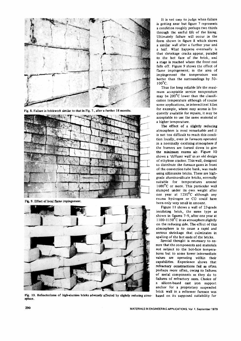
Fig. 8. Failure in brickwork similar to that in Fig. 7., after a further 18 months.
Fig. 9. Effect of local flame impingement.
Fig. 10. Refractoriness of high-alumina bricks adversely affected by slightly reducing atmo- sphere.
It is not easy to judge when failure is gett ing near but figure 7 represents a condi t ion roughly perhaps two thirds through the useful life of the lining. Ul t imately failure will occur in the form shown in figure 8 which shows a similar wall after a further year and a half. What happens eventually is that shrinkage cracks appear, parallel to the hot face of the brick, and a stage is reached where the front end falls off. Figure 9 shows the effect of f lame impingement ; in the area of impingement the temperature was hot ter than the surroundings by 50- I O0°C.
Thus for long reliable life the maxi- mum acceptable service temperature may be 200°C lower than the classifi- cation temperature al though of course some applications, in in termi t tent kilns for example, where easy access is fre- quent ly available for repairs, it may be acceptable to use the same material at a higher temperature.
The effect of a slightly reducing atmosphere is most remarkable and it is not too difficult to reach this condi- t ion locally, even in furnaces operated in a nominal ly oxidising atmosphere if the burners are turned down to give the min imum excess air. Figure 10 shows a 'diffuser wall' in an old design of e thylene cracker. This wall, designed to distribute the furnace gases in front of the convect ion tube bank, was made using siUimanite bricks. These are high- grade alumino-silicate bricks, normally suitable for temperatures around 1600°C or more. This particular wall slumped under its own weight after one year at 1250°C although any excess hydrogen or CO could have been only very small in amount .
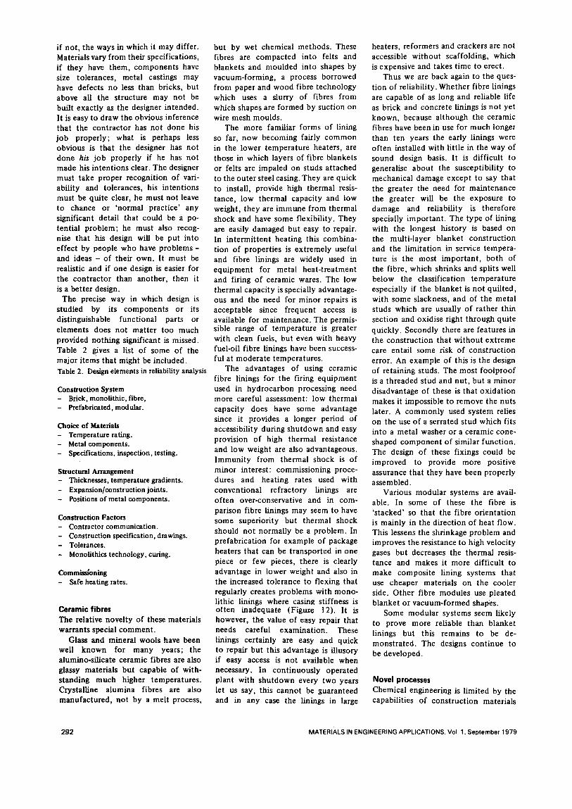
Figure I 1 shows a wall of 23-grade insulating brick, the same type as shown in figures 7-9, after one year at 1100-1150°C in an a tmosphere slightly on the reducing side. The effect of this a tmosphere is to cause a rapid and serious shrinkage that culminates in spalling o f the hot ends of the bricks.
Special thought is necessary to en- sure that the components and materials not subject to the hot-face tempera- tures but to some lower intermediate values are operating within their capabilities. Experience shows that refractory construct ions fail as of ten perhaps more often, owing to failures o f metal components as they do to failures o f refractory ones. Choice of a silicon-based cast iron support anchor for a proprietary suspended brick wall in a reformer furnace was based on its supposed suitability for
290 MATERIALS IN ENGINEERING APPLICATIONS. Vol 1. September 1979
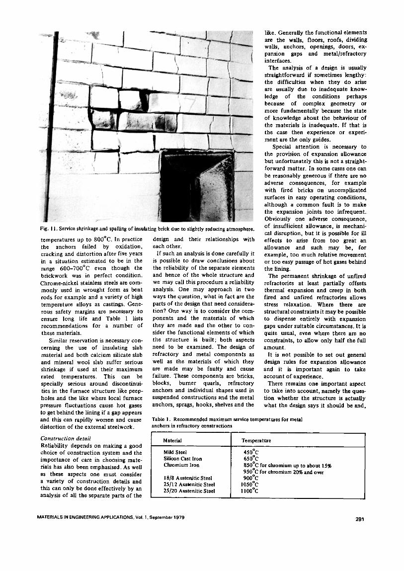
Fig. 11. Service shrinkage and spaUing of insulating brick due to slightly reducing atmosphere.
temperatures up to 800°C. In practice the anchors failed by oxidation, cracking and distortion after five years in a situation estimated to be in the range 600-700°C even though the brickwork was in perfect condition. Chrome-nickel stainless steels are com- monly used in wrought form as bent rods for example and a variety of high temperature alloys as castings. Gene- rous safety margins are necessary to ensure long life and Table 1 lists recommendations for a number of these materials.
Similar reservation is necessary con- cerning the use of insulating slab material and both calcium silicate slab and mineral wool slab suffer serious shrinkage if used at their maximum rated temperatures. This can be specially serious around discontinui- ties in the furnace structure like peep- holes and the like where local furnace pressure fluctuations cause hot gases to get behind the lining if a gap appears and this can rapidly worsen and cause distortion of the external steelwork.
Construction detail Reliability depends on making a good choice of construction system and the importance of care in choosing mate- rials has also been emphasised. As well as these aspects one must consider a variety of construction details and this can only be done effectively by an analysis of all the separate parts of the
design and their relationships with each other.
If such an analysis is done carefully it is possible to draw conclusions about the reliability of the separate elements and hence of the whole structure and we may call this procedure a reliability analysis. One may approach in two ways the question, what in fact are the parts of the design that need considera- tion? One way is to consider the com- ponents and the materials of which they are made and the other to con- sider the functional elements of which the structure is built; both aspects need to be examined. The design of refractory and metal components as well as the materials of which they are made may be faulty and cause failure. These components are bricks, blocks, burner quarls, refractory anchors and individual shapes used in suspended constructions and the metal anchors, sprags, hooks, shelves and the
like. Generally the functional elements axe the walls, floors, roofs, dividing walls, anchors, openings, doors, ex- pansion gaps and metal/refractory interfaces.
The analysis of a design is usually straightforward ff sometimes lengthy: the difficulties when they do arise are usually due to inadequate know- ledge of the conditions perhaps because of complex geometry or more fundamentally because the state of knowledge about the behaviour of the materials is inadequate. If that is the case then experience or experi- ment are the only guides.
Special attention Ls necessary to the provision of expansion allowance but unfortunately this is not a straight- forward matter. In some cases one can be reasonably generous ff there are no adverse consequences, for example with fired bricks on uncomplicated surfaces in easy operating conditions, although a common fault is to make the expansion joints too infrequent. Obviously one adverse consequence, of insufficient allowance, is mechani- cal disruption, but it is possible for ill effects to arise from too great an allowance and such may be, for example, too much relative movement or too easy passage of hot gases behind the lining.
The permanent shrinkage of unfired refractories at least partially offsets thermal expansion and creep in both fired and unfired refractories allows stress relaxation. Where there axe structural constraints it may be possible to dispense entirely with expansion gaps under suitable circumstances. It is quite usual, even where there are no constraints, to allow only half the full amount.
It is not possible to set out general design rules for expansion allowance and it is important again to take account of experience.
There remains one important aspect to take into account, namely the ques- tion whether the structure is actually what the design says it should be and,
Table 1. Recommended maximum service temperatures for metal anchors in refractory constructions
Material Temperature
Mild Steel Silicon Cast Iron Chromium Iron
18/8 A ustenJtic Steel 25/12 Amtenitic Steel 25/20 Austenitic Steel
450°C 650°C 850°Cforchromium up to about15% 950°Cforchromium 20%and over 900°C
1050°C IIO0°C
MATERIALS IN ENGINEERING APPLICATIONS. Vol. 1. September 1979 291
if not, the ways in which it may differ. Materials vary from their specifications, if they have them, components have size tolerances, metal castings may have defects no less than bricks, but above all the structure may not be built exactly as the designer intended. It is easy to draw the obvious inference that the contractor has not done his job properly; what is perhaps less obvious is that the designer has not done his job properly if he has not made his intent ions clear. The designer must take proper recognition of vari- ability and tolerances, his intentions must be quite clear, he must not leave to chance or 'normal practice ' any significant detail that could be a po- tential problem; he must also recog- nise that his design will be put into effect by people who have p r o b l e m s - and ideas - of their own. It must be realistic and if one design is easier for the contractor than another, then it is a better design.
The precise way in which design is studied by its components or its distinguishable functional parts or elements does not mat ter too much provided nothing significant is missed. Table 2 gives a list of some of the major items that might be included. Table 2. Design elements in reliability analysis
Construct ion S y s t e m - Brick, monolithic, fibre, - Prefabricated, modular.
Choice o f Materials Temperature rating.
- Metal components. - Specifications, inspection, testing.
Structural Arrangement - Thicknesses , t emperature gradients . - E x p a n s i o n / c o n s t r u c t i o n jo ints . - Posit ions o f meta l c o m p o n e n t s .
Construct ion Factors - Contractor c o m m u n i c a t i o n . - Construction specification, drawings. - Tolerances . - Monolithics technology, curing.
Commiss ion ing - Safe heating rates.
Ceramic fibres The relative nove l ty o f these materials warrants special comment .
Glass and mineral wools have been well known for many years; the alumino-silicate ceramic fibres are also glassy materials but capable of with- standing much higher temperatures. Crystalline alumina fibres are also manufactured, not by a melt process,
but by wet chemical methods. These fibres are compacted into felts and blankets and moulded into shapes by vacuum-forming, a process borrowed from paper and wood fibre technology which uses a slurry of fibres from which shapes are formed by suction on wire mesh moulds.
The more familiar forms of lining so far, now becoming fairly common in the lower temperature heaters, are those in which layers of fibre blankets or felts are impaled on studs attached to the outer steel casing. They are quick to install, provide high thermal resis- tance, low thermal capacity and low weight, they are immune from thermal shock and have some flexibility. They are easily damaged but easy to repair. In in termit tent heating this combina- tion of properties is extremely useful and fibre linings are widely used in equipment for metal heat- t reatment and firing of ceramic wares. The low thermal capacity is specially advantage- ous and the need for minor repairs is acceptable since frequent access is available for maintenance. The permis- sible range of temperature is greater with clean fuels, but even with heavy fuel-oil fibre linings have been success- ful at moderate temperatures.
The advantages of using ceramic fibre linings for the firing equipment used in hydrocarbon processing need more careful assessment: low thermal capacity does have some advantage since it provides a longer period of accessibility during shutdown and easy provision of high thermal resistance and low weight are also advantageous. Immuni ty from thermal shock is of minor interest: commissioning proce- dures and heating rates used with convent ional refractory linings are often over-conservative and in com- parison fibre linings may seem to have some superiority but thermal shock should not normally be a problem. In prefabrication for example of package heaters that can be transported in one piece or few pieces, there is clearly advantage in lower weight and also in the increased tolerance to flexing that regularly creates problems with mono- lithic linings where casing stiffness is often inadequate (Figure 12). It is however, the value of easy repair that needs careful examination. These linings certainly are easy and quick to repair but this advantage is illusory if easy access is not available when necessary. In continuously operated plant with shutdown every two years let us say, this cannot be guaranteed and in any case the linings in large
heaters, reformers and crackers are not accessible wi thout scaffolding, which is expensive and takes t ime to erect.
Thus we are back again to the ques- tion of reliability. Whether fibre linings are capable of as long and reliable life as brick and concrete linings is not yet known, because although the ceramic fibres have been in use for much longer than ten years the early linings were often installed with little in the way of sound design basis. It is difficult to generalise about the susceptibility to mechanical damage except to say that the greater the need for maintenance the greater will be the exposure to damage and reliability is therefore specially important . The type of lining with the longest history is based on the multi-layer blanket const ruct ion and the l imitat ion in service tempera- ture is the most important , both of the fibre, which shrinks and splits well below the classification temperature especially if the blanket is not quil ted, with some slackness, and of the metal studs which are usually of rather thin section and oxidise right through quite quickly. Secondly there are features in the construct ion that wi thout extreme care entail some risk of const ruct ion error. An example of this is the design of retaining studs. The most foo lproof is a threaded stud and nut, but a minor disadvantage of these is that oxidat ion makes it impossible to remove the nuts later. A commonly used system relies on the use of a serrated stud which fits into a metal washer or a ceramic cone- shaped componen t of similar funct ion. The design of these fixings could be improved to provide more positive assurance that they have been properly assembled.
Various modular systems are avail- able. In some of these the fibre is 's tacked' so that the fibre or ienta t ion is mainly in the direction of heat flow. This lessens the shrinkage problem and improves the resistance to high velocity gases but decreases the thermal resis- tance and makes it more difficult to make composi te lining systems that use cheaper materials on the cooler side. Other fibre modules use pleated blanket or vacuum-formed shapes.
Some modular systems seem likely to prove more reliable than blanket linings but this remains to be de- monstrated. The designs cont inue to be developed.
Novel processes Chemical engineering is l imited by the capabilities of construct ion materials
292 MATERIALS IN ENGINEERING APPLICATIONS. Vol 1. September 1979
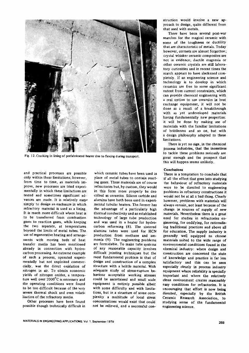
Fig. 12. Cracking in fining of prefabricated heater due to flexing during transport.
and practical processes are possible only within these limitations; however, from time to time, as materials im- prove, new processes are tried experi- mentally in which these limitations are tested and sometimes significant ad- vances are made. It is relatively easyJ simply to design an enclosure in which refractory material is used as a lining. It is much more difficult where heat is to be transferred from combustion gases to reaction gases, while keeping the two separate, at temperatures beyond the limits of metal tubes. The use of regenerative heating and arrange-
ments with moving beds of heat transfer media has been mentioned already in connection with hydro- carbon processing. An extreme example of such a process, operated experi- mentally but not exploited commer- cially, was the direct oxidation of nitrogen in air. To obtain economic yields of nitrogen oxides, a tempera- ture well over 2000°C is necessary and the operating conditions were found to be too difficult because of the very severe thermal shock and even volati- lisation of the refractory media.
Other processes have been found possible though technically difficult in
which ceramic tubes have been used in place of metal tubes to contain react- ing gases. These materials are of course refractories but, by custom, they would in this form more properly be des- cribed as ceramics. Silicon carbide and alumina have both been used in experi- mental tubular heaters. The former has the advantage of a particularly high thermal conductivity and an established technology of large tube production and was used in a heater for hydro- carbon reforming (8). The sintered alumina tubes were used for HCN production from methane and am- monia (9). The engineering problems are formidable. To make tube systems of any reasonable capacity involves difficult jointing techniques but the most fundamental problem is that of design and construction of a complex structure with a brittle material. With adequate study of stress-rupture be- haviour acceptable working stresses could be ascertained and small scale equipment is entirely possible albeit with some difficulty and with limita- tions, but in a structure of some com- plexity a multitude of local stress concentrations would exist that could not be relieved, and a successful con-
struction would involve a new ap- proach to design, quite different from that used with metals.
There have been several post-war searches for the magical ceramic with some of the toughness or ductility that are characteristic of metals. Today however, cermets are almost forgotten; crystal whisker ceramic composites are not in evidence; ductile magnesia or other ceramic crystals are still labora- tory curiosities and in recent times the search appears to have slackened com- pletely. If an engineering science and technology is to develop in which ceramics are free to some significant extent from current constraints, which can provide chemical engineering with a real option to use ceramics in heat exchange equipment, it will not be done as a result of a breakthrough with as yet undeveloped materials having fundamentally new properties: it will be done by making use of materials with the familiar limitations of brittleness and so on, but with a design philosophy adapted to these limitations.
There is yet no sign, in the chemical process industries, that the incentives to tackle these problems seriously are great enough and the prospect that this will happen seems unlikely.
Conclusions There is a temptation to conclude that if all the effort that goes into studying the behaviour of refractory materials were to be directed to engineering problems in refractory constructions it would not be at all a bad thing. Clearly however, problems with materials will always remain, not least because of the change in sources of supply of new materials. Nevertheless there is a great need for studies in refractories en- gineering, for codifying, for rationalis- ing traditional practices and above all for education. The supply industry is generally well equipped to choose materials suited to the wide range of environmental conditions found in the chemical industry: where design and construction are concerned the state of knowledge and practice is far less satisfactory and this can be s e e n
especially clearly in process industry equipment where reliability is specially important and where the relatively clean environment creates reasonably easy conditions for refractories. It is encouraging that effort is now being directed, especially by the British Ceramic Research Association, to studying some of the fundamental engineering science.
MATERIALS IN ENGINEERING APPLICATIONS. Vol. 1. September 1979 293
References 1. Unpublished work carried out by the
author. 2. Rotary Cement Kiln Linings: Refrac-
tory Problems in the Burning Zone, L. G. Huggett,Trans., Brit., Cetera., Soc., 56, (3), 1957.
3. Radial Deformation in Rotary Kilns, L. G. Huggett, ibid., 66, (2), 1967.
4. Photographs by courtesy of British Ceramic Research Association.
5. The Spinela and their Relationship to Chrome Ores, G. R. Rigby, 'Ceramics, A Symposium', British Ceramic Society, 1953.
6. Transfer of Silica in the Pressure Steam Reforming Process, L. G. Huggett and L. Piper, 'Materials Technology in Steam Reforming Processes', Pergamon Press, 1964.
7. Illustrations by courtesy of Metagurgical Engineers Limited.
8. H. Madeheim, American Gas Journal, 1950, page 8.
9. F. Endter, Chemie-lng-Technik, 1958, 30,305.
B C I R A / E S I M a n u a l on
Refractories for Coreless Induction Furnaces for Ironfoundries
The manual should prove to be of interest to all existing users of coreless induction melting furnaces and of considerable assistance to those contemplating the use of such equipment.
Sections in the manual include the following:
Description of coreless furnace and lining
Available refractory materials
Furnace lining techniques
Methods of installation
The fritting of linings
Operation practices
Measurement of lining wear in coreless induction furnaces
Repairs of l inings
Some common causes of lining failure
Induction furnace knock-out procedure
Maintaining records
For further information contact:
BClRA, Alvechurch, Birmingham B48 7QB
294 MATERIALS IN ENGINEERING APPLICATIONS. VoL 1. September 1979