
REFRACTIVE X-RAY LENSES NEW DEVELOPMENTS
63
1 REFRACTIVE X-RAY LENSES NEW DEVELOPMENTS BRUNO LENGELER PHYSICS DEPARTMENT RWTH AACHEN UNIVERSITY (Grenoble, July 2010)
Transcript of REFRACTIVE X-RAY LENSES NEW DEVELOPMENTS

1
REFRACTIVE X-RAY LENSES
NEW DEVELOPMENTS
BRUNO LENGELER
PHYSICS DEPARTMENT
RWTH AACHEN UNIVERSITY
(Grenoble, July 2010)

2
A. Strategy for refractive x-ray lenses > have been considered as not feasible for a long time
> visible light: index
of refraction
n = 1 +
with
~ 0.5 for
glass
* refraction
strong * absorption
weak
* focal
length
short * focusing
lens
convex
> x-rays: n = 1 –
i
with
~ 10-6
and positive
* refraction
weak * absorption
strong
* focal
length
long * focusing
lens
concave
„There
are
no refractive
lenses
for
x-rays!“
W.C.Roentgen BUT: refraction is not zero and absorption is not infinite!
1m1m
~ 100m~ 100m

3
Design of refractive x-ray lenses
lensmaker formula: or
in Angstrom
in g/cm³
Z atomic
number A atomic
mass
in g
To obtain
a small focal length:
i)
small
radius
of curvature
R: typical: R = 50 to 1500µm
ii)
high density
of lens
material
iii) profile
must
be
parabolic: no spherical
aberration
2 62.70( Z / A)10
1 2(1 n)f R
Rf2

4
LensLens surfacessurfaces mustmust bebe paraboloidsparaboloids of rotationof rotation
single lenssingle lens parameters for Be parameters for Be lenseslenses::
parabolic
profile: no spherical
aberration
focusing
in full plane
=> excellent
imaging
optics
R = 50 to 1500R = 50 to 1500µµmm
2R2R00
= 0.45 to 2.5mm= 0.45 to 2.5mm
d d belowbelow
3030µµmm
Presenter
Presentation Notes
At ID22: Standard optics for imaging and microanalysis above 10keV ESRF machine: high resolution beam monitor
5
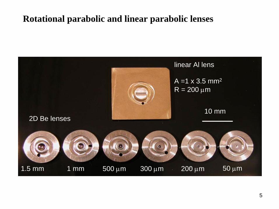
Be / AL parabolic lenses (Aachen)
50 m500 m1.5 mm 300 m 200 m1 mm
2D Be lenses
linear Al lens
A =1 x 3.5 mm2
R = 200 m
10 mm
Rotational parabolic and linear parabolic lenses

6
Linear Be lenses (cylinder paraboloids)
length
2.5mm
R=500µm R=1500µm

7
SEM image of linear Be lens (R=500µm)

8
Refractive x-ray lenses available at Aachen University
•
material: Be 6 to 40 keV Al 40 to 80 keV Ni 80 to 150 keV
•
profile: rotationally
parabolic
(2D) cylinder
parabolic
(1D)
• radii
R at apex
and geometric
aperture
2R0
R = 50, 100, 200, 300, 500, 1000, 1500µm 2R0
= 450, 632, 894, 1095, 1414, 2000, 2450µm
length
of 1D-lenses: 2.5mm
•
small
radii
for
imaging
and focusing large radii
for
prefocusing
9
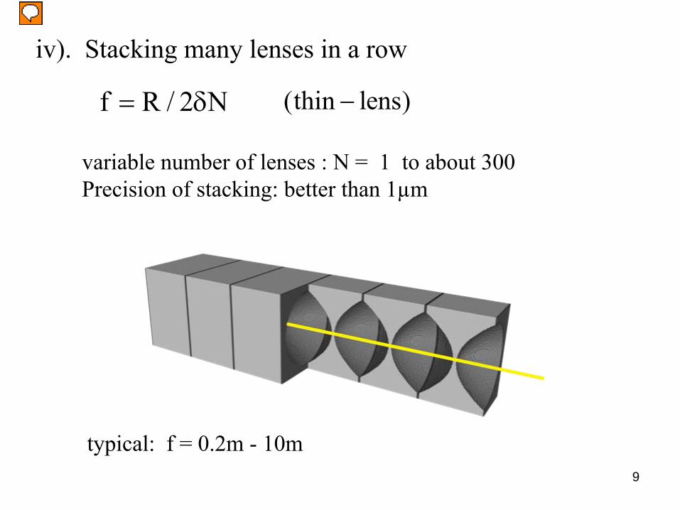
iv). Stacking many lenses in a row
variable number
of lenses
: N = 1 to about
300Precision
of stacking: better
than
1µm
typical: f = 0.2m -
10m
f R / 2 N (thin lens)
Presenter
Presentation Notes
At ID22: Standard optics for imaging and microanalysis above 10keV ESRF machine: high resolution beam monitor

10
NEW LENS CASING (can
be integrated
in vacuum
of beam
line)

11
A few
examples: for 1m focal length by lenses with R=50µm
E (keV) material 2
(10-6) N f (m)
12.4 Be 4.4341 11 1.025
17 Be 2.3591 21 1.009
40 Be 0.4261 117 1.003
40 Al 0.6746 74 1.002
80 Al 0.1687 296 1.002
80 Ni 0.5515 91 0.996
12
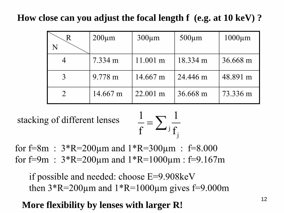
How close can you adjust the focal length f (e.g. at 10 keV) ?
stacking
of different lenses
for
f=8m : 3*R=200µm and 1*R=300µm : f=8.000 for
f=9m : 3*R=200µm and 1*R=1000µm : f=9.167m
if
possible
and needed: choose
E=9.908keV then
3*R=200µm and 1*R=1000µm gives
f=9.000m
More flexibility by lenses with larger R!
R N
200µm 300µm 500µm 1000µm
4 7.334 m 11.001 m 18.334 m 36.668 m
3 9.778 m 14.667 m 24.446 m 48.891 m
2 14.667 m 22.001 m 36.668 m 73.336 m
jj
1 1f f

13
v). Lens
material must
be
mechanically, thermally and chemically
stable
vi). low Z lens
material:
mass
absorption
cofficient
~ Z³
/ E³
candidates: Be, B, C, Al, Si, Ni

14
Attenuation of x-rays in typical lens materials
Ultimately, Compton scattering limits transmission
at high x-ray
energies!

15
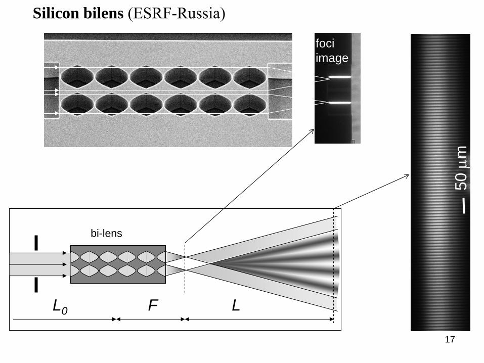
Cylinder parabolic (1D) lenses from ESRF-Russia and
from TU Dresden
material: Si
technology: microfabrication
(e-beam
lithography, etching)
performance: stapling
is
done
by
microfabrication
bilenses
possible
very
small
radii
possible, (down to 1µm) => very
small
focal
length
only
1D-
lenses

16
NanofocusingNanofocusing LensesLenses (NFL)(NFL)
lens
made of Si by
e-beam
litho-
graphy
and deep
reactive
ion etching!
strong
lenscurvature:
N = 35 -
140
Schroer
et al APL 82, 1485 (2003)
nanolens
500 m
singlelens
100 m
optical axisR = 1µm -
5µm
17
50
m
Si bi-lens chip
L0 F L
bi-lens
fociimage
far-field interference
X-ray bilens
= L/ d
d
Silicon bilens (ESRF-Russia)

18
B. Properties of refractive x-ray lensesIn the
following
we
consider
mainly
Be, Al and Ni
1. Energy range
Be : about
5 to 40keV
d guaranteed
below
50µm, typically
30µm
Al : about
30 to 80 keV
d guaranteed
below
30µm, typically
22µm
Ni : about
80 to 150 keV
d guaranteed
below
20µm, typically
10-16µm

19
2. Comparison parabolic versus spherical lensparabolic spherical
al
25µm
spherical lenses are inappropriate for imaging!

20
Example: Ni mesh
12.7µm period
parabolic
refractive
Be lens
N = 91, R = 200µm f = 495 mm at 12 keV
magnification: 10
detector: high resolution
film
NO DISTORTION!
21
3. Material properties
Beryllium
manufactured
by
powder
metallurgy contains
up to 1wt% of BeO
contains
many
grain
boundaries => small angle x-ray scattering
results
in background
radiation
density
: 1.85 g/cm³
melting
point : 1287 °C
recrystallisation: about
600°C
main
supplier: BRUSH-WELLMAN

22
Small-angle x-ray scattering in different types of Be
PF-60 is
standard
Be from
BW IF-1 has 20 times
less
SAXS than
PF-60
only
2 times
more
SAXS than
single
crystal
(EK)

23
Small angle scattering of different lens materials
Be
single
crystal
5 * 104
Th
/nm³
at 0.0565° Be IF-1 10 or
Q=10-2 /A
Be PF-60 238 Be russian
47
Al 5N 90
B HCStarck
20
diamond
14 PMMA 2 Teflon CF2
770 Pyro-graphite
200
glassy
carbon
1000-10000
sapphire
Al2
O3 2

24
Lens material: metals versus resistsmetals resists
Be Al Ni PMMA, Kapton, SU-8,…
radiation damage none yes
heat conductivity 200 237 91 ca 0.2 (W/m.K)
melting point (°C) 1277 660 1453 ca 200
SAXS low to medium low to high
density 1.85 2.7 8.9 ca 1.1
form 1D and 2D only 1D
Rmin 50µm 10µm
kinoform no yes

25
X-ray absorption in SU-8
SU-8 contains
1 atom
of Sb per formula
unit! SU-8: no advantage
compared
to Be and Al !

26
4. Aperture of paraboloid of rotation:
* no spherical
aberration
* focusing
in full
plane
=> excellent
imaging
optics
* radius
R and aperture
2R0
are
decoupled
spherical
lens: parabolic
lens:
R0 and R independentR0
≤
R

27
Effective lens aperture Deff
Absorption reduces
the
effective
aperture
below the
value
of the
geometric
aperture
2R0
Lst
2R0
eff 0 p p
p 0 st
D 2R 1 exp a a
1a µNz µL2
02z

28
Transmission T versus effective aperture Deff (Aeff )
transmission T: fraction
of transmitted
intensity
compared
to intensity
falling
on geometric
aperture
R0
²
0R
p2 00 p
2p 0 0
1 1T exp( µN2z) [1 exp( 2a )]R 2a
a µNR / 2R µNz
eff 0 p pD 2R [1 exp( a ) / a
effective aperture Deff reduced
by
absorption compared
to geometric
aperture
2R0

29
Example: Be stack
with
N = 50, R = 50µm at 17 keV 2= 2.359 10-6
and µ
= 0.4903/cm
f = 423.9mm
z0 (µm)
2R0 (µm)
Deff (µm)
T
500 447.2 339.5 37.3%
1000 632.5 386.2 20.2%
100 98.5 94.1%
The
effective
aperture
is
the
relevant parameter
for characterizing
the
transmission
of refractive
lenses!

30
Influence of material (thickness d ) between apices on transmission of lensstack
Transmission = exp(-µNd)
Example
: Be lenses
R=50µm, d=30µm
1. 12keV, µ=0.8196/cm, N=22, f=0.480m
transmission: 94.7%
2. 17keV, µ=0.4903/cm N=42, f=0.505m
transmission: 94.0%

31Water
cooled
beryllium
lens
at ESRF (ID10)
5. Thermal stability in the beam

32
Temperature
-
time profile
in white
beam
at ID10 ESRF ca. 100 W/mm²
& total 40 W
(Be lens)
0 2 4 6 8 10 1220
30
40
50
60
70
Refill
Tem
pera
ture
(°C
)
Time (h)
0 .00 0.05 0 .10 0.15 0.2 0 0.25 0.3 020
30
40
50
60
70
Tem
per
atu
re (
°C)
T im e (h )
In Be lenses
the
temperature
should
not
exceed about
300°C!

33
6. Insensitivity of lenses to surface roughness and contamination (compared
to mirrors)
mirror lens stack
Damping
of intensity
due
to surface
roughness
~ exp[-Q²
²]
with
momentum
transfer
Q = 2k sin1
2k 1
mirror Q = 1.4 10–1
A-1
at 1
= 0.6°
and
= 1A
lens stack Q = N1/2
k
= 1.4 10–4
A–1 at N = 100 and
= 1A
A lens is about 1000 times less sensitive to
than a mirror!

34
Typical value of surface roughness of our lenses: 0.1µm
For l = 1A N = 100 Q = 1.4 10-4 /A
exp(-Q²s²) = 0.981
This
is
tolerable!

35
7. Chromatic aberration
refractive
x-ray
lenses
show
strong
chromatic
aberration
f = R/2N
= 2.70
²
Z/A
Changing
the
energy
at fixed
focal
length implies
changing
the
number
of lenses
in the
stack!
solution: TRANSFOCATOR developed
at ESRF
flexible change
of f
in air
and in vacuum
new
type
of monochromator

36
TRANSFOCATOR (ESRF development)

37
8. Thick lenses
* if
L << f (thin
lens): f0
= R / 2N
* if
L comparable
to f : rays
are
bent
towards
optical
axis inside
lens
0r(z) R cos z 2RF
Refracting
power/length F: thickness
of lens
platelet

38
Minimal focal length achievable with Be, R = 50µm at 17 keV
=> effective aperture : 295µm
=> best lateral resolution: 42nm (diffraction limit)

39
For lenses with constant refracting power:
number
of lenses
in the
stack
can
be
reduced
slightly
without loss
of performance
(the
last lenses
do not
refract
any
more)

40
Adiabatically focusing lenses (PRL 94, 054802(2005))
the
refractive
power
per unit
length
increases
along
the
lens!
0i
0i
0f
RfR4 lnR

41
Adiabatically focusing lenses
2R0i
and 2R0f
entrance
and exit
diameter
focal
length
length
of stack
effective
aperture
0i
0i
0f
RfR4 lnR
0i 0i
0f
R RL (ln )R4
eff 0i pp
p
1D 2R (1 exp( a )a
a µL/ 2

42
Two examples of adiabatically focusing lenses
1. rotationally parabolic Be lenses at 17 keV (2
= 2.359 10-6)
Ri
= 1500µm, R0i = 1224.7µm Rf
= 50µm, R0f
= 223.6µm
=> f = 432.4mm L = 983.2mm Deff
= 498.9µm dtr = 52.2nm
compared
to dtr = 42.0nm for
thick
lens with
maximum
length:
R = 50µm, N=162, L=324mm, f=205.9mm, Deff
= 295.0µm
not worth the effort!

43
2. Cylinder paraboloids (C.Schroer TU Dresden)
a. adiabatically
focusing
diamond lenses
at 27.6keV
R0i
= 9.43µm R0f
= 50nm (Rf
= 25nm) N = 1166
dtr = 4.7nm (11.6µm behind
stack) diffraction limit
compared
to
b. nanofocusing
diamond lens
with
constant
aperture
N = 200 R = 1.31µm
R0
= 7.2µm
dtr = 14.2nm diffraction limit

44
9. Handling and adjustment
a. refractive
lenses
are
robust and compact:
easily
installed
and removed in its
own
lens
casing
or
in the
vacuum
of the
beam
line
b. focus stays on axis:
fast adjustment
(typically
in 15 minutes) relatively
insensitive
to misorientation
to vibrations no need
for
readjusment
of the
beam-line
components
downstream
c. comfortable working distance between optics and sample
REFRACTIVE LENSES: NO RACING HORSES BUT EXCELLENT WORKING HORSES !

45
C. Applications of refractive x-ray lenses
refractive x-ray lenses can be used like glass lenses are used
for visible light
but
the numerical aperture N.A. is very small
typically 10-4 to 10-3

46
New and improved x-ray techniques
1. Imaging: x-ray
microscopy: 2D image x-ray
tomography: 3D reconstruction
in absorption
and phase
contrast
2. Focusing: diffraction, spectroscopy…..
with
high lateral resolution in the
sub
100 nm range
(50 nm were
reached)
3. Coherent photon flux: X-ray
diffraction
speckle
spectroscopy

47
objectivecondenser 2HRX-ray CCD
54 m 6 m0.2 – 0.3 m
1. High-resolution x-ray microscopy
illumination
of object
from
behind
via prefocusing lens (condenser
2) in order to adjust
beam
size
on sample
objective with small focal length and low distortion (rotationally
parabolic) see
below: dtr
about
50nm
large magnification
in order to relieve
requirements on CCD camera
(object
slightly
outside
focus)
A. Snigirev
et al

48
-1.0 -0.5 0.0 0.5 1.00
200000
400000
600000
0.55 mm
39 CRLs no CRLs
Inte
nsity
Vertical position
15 m
-2.0 -1.5 -1.0 -0.5 0.0 0.5 1.0 1.5 2.00
20000
40000
60000
80000
100000
1.57 mm
39 CRLs no CRLs
Inte
nsity
Horizontall position
239 m
PREFOCUSING with
rotationally parabolic Be lenses
( R = 1500µm)
Image of the
ID18 source
at ESRF
14.4125eV
39 Be lenses R = 1500µm
f = 11.718m
geometric
aperture: 2.5mm
(A. Chumakov
ESRF)

49
Intensity profile in the horizontal: ID18
well fitted by a Gaussian with 239 µm FWHM

50
Prefocusing with linear lenses Be, Al and Ni
R = 50 to 1500mm length
2.5 mm
*
collecting
more
intensity
* for
making
spot
on sample
more
circular
(on storage
rings)

51
FWHM = 10 m
1D- Be lensesR = 500µm 2.7 mm long
E = 10 keVN = 20R = 500 mmL1
= 56.5 mL2
= 3.91 mAeff
= 690 mmSnigirev …

52
1mm
m
1m
0.5m
0.25m
High Energy X-ray Microscopy at ID15 Al lenses
E = 46 keV
M. Di MichielM. ScheelA. SnigirevI. Snigireva
Siemens starTa 0.5 m

53
condenser 1 sampleLarge areaX-ray CCD
2 mX-rays
Microscopy in diffraction mode
Be N = 19 , R = 300µm

54
F = 1.3 mL = 55 m
CRLsample
2D detector
source
M. Drakopoulos, A. Snigirev, I. Snigireva, J. Schilling, Applied Physics Letters, 86, 014102, 2005.
E = 28 keVAl CRL, N = 112, F = 1.3 m
CCD resolution 2 mpixel /
= d
Resolution is limitedby angular source size: s/L ~ 1 rad
Momentum transferResolution: 10-4 nm-1
Si photonic crystala=b=4.2 m d01 =3.6 m d11 =2.1 m
Lattice vectors g01 =1.75·10-3 nm-1 g11 =3·10-3 nm-1
X-ray High Resolution Diffraction Using Refractive Lenses
Presenter
Presentation Notes
In reciprocal space, the corresponding lattice vectors g01 and g11 we are able to resolve have the lengths 1.75∙10-3 nm-1 and 2.99∙10-3 nm-1, respectively

55
2. Focusing
Microscopy Object
placed
close
to
secondary
source: => strong
magnification
The
smaller
the
focus, the
sharper
the
image!
Spectroscopy, tomography large depth
of field
scanning
beam
over
sample (diffraction, SAXS, XAS, fluorescence…)

56
Small focus requires
1. small
source
2. long
distance L1
source-lens
3. small
focal
length
and large effective
aperture
of lens

57
Example: ID13 at ESRF
Be lens: R = 50µm, N = 162, f = 205.9mm, Deff
= 295µm, dtr
= 42nm
L1
= 100m, L2 = 206.3mm
geometric
image of source 2
1
LS SL
FWHM S (µm)
S‘
geom (nm)
S‘
incl
diffr (nm)
horizontal 120 248 251
vertical 20 41 59
diffraction limited in the vertical !

58
3. Coherent flux
* diffraction
of individual
large molecules, nanoparticles
* speckle
spectroscopy
Illuminated area on sample must be smaller than the lateral coherence area at the sample position. Then all monochromatic photons are undistinguishable, i.e. they are in the same mode!
* coherent
photon
flux
is
a property
of the
brillance
B of the source
and of the
degree
of monochromaticity
2cF B
* the
coherent
flux
can
at best be
conserved, it
cannot
be
increased
by
a focusing
optic.

59
Example: low-betha undulator at ESRF
1. Be lenses, 17 keV, N = 162, f = 205.9mm, dtr = 42nm
L1
= 100 m, L2
= 0.2063 m
2.
Source
size FWHMGeometric
image
FWHMhorizontal 120µm 248 nm
vertical 20µm 41nm
Image is
diffraction
limited
in the
vertical: => coherent
illumination
in the
vertical
Not so in the
horizontal!

60
3. remedy for horizontal direction
*
insert
a linear lens
(prefocussing
lens) which
focuses only
in the
horizontal
* the
secondary
source
S‘
must
have
a lateral coherence
length at the
postion
of lens
2 which
is
equal
to the
effective
aperture
of lens2.
S S‘Prefocusing
lens Lens
250m 50m

61
Prefocusing lens
Be linear: R = 500µm, N = 55, f = 3.854m, Deff
= 1048µm
Image S‘
at b1
= 4.168m behind
horizontal lens
lateral (horizontal) coherence length at position of lens 2: 295µm
this
is
equal
to Deff
of lens
2: only
the
coherent
flux
passes through
lens
2, the
rest
is
peeled
off.
gain
in flux
(compared
to no prefocusing): about
factor
10.

62
MANY THANKS
to
Anatoly and Irina Snigirev from ESRF
Christian Schroer and collaborators from TU Dresden
Herbert Schloesser from our workshop
for many years of efficient and pleasant collaboration

63