
References. - Springer978-3-7091-2991-3/1.pdf · opticeskom metode", Izv. Akad. Nauk SSSR, ......
48
193 References. [1J E.G. Coker, L.N.G. Filon : "A Treatise on Photo- elasticity" ; Cambridge, At the Uni- versity Press, 1957. [2] H.T. Jessop: "Photoelasticity" ; Handbuch der Physik, Band VI, Springer, 1958. [3] J. W. Dally, W. F. Riley : "Experi:mental Stress Analysis"; Mc Graw<-IlLII, New York, 1965. [4J E.H. Dill : "On the Theory of Photoviscoelasticity" Univ. of Washington, Dept. Aeronautics and Astronautics, Report 63-1, January, 1963. [5 J J. T. Pindera : "Response of Photoelastic Systems"; Solid Mech. Div., Univ. of Waterloo, Ontario, Canada, Report 17, August, 1969. [6J H. Wolf: "Spannungsoptik" ; Springer, 1961. [7] J.A. Straton : "Electromagnetic Theory" ; Mc Graw Hill, 1941. [8J C. Truesdell, R. Toupin: "The Classical Field Theories" ; Enc. of Ph., V 111/1, Springer, 1960. [9] R. D. [10J R.C. Mindlin, L. E. Goodman : liThe Optical Equa- tions of Three-dimensional Photoelas- ticity" ; Jnl. of Appl. Ph., 20, (1), 89-97, (1949). O!Rourke : "Three-dimensional Photoelasticity"; Jnl. Appl. Ph., (7), 872-878, (1951) .
Transcript of References. - Springer978-3-7091-2991-3/1.pdf · opticeskom metode", Izv. Akad. Nauk SSSR, ......

193
References.
[1J E.G. Coker, L.N.G. Filon : "A Treatise on Photoelasticity" ; Cambridge, At the University Press, 1957.
[2] H.T. Jessop: "Photoelasticity" ; Handbuch der Physik, Band VI, Springer, 1958.
[3] J. W. Dally, W. F. Riley : "Experi:mental Stress Analysis"; Mc Graw<-IlLII, New York, 1965.
[4J E.H. Dill : "On the Theory of Photoviscoelasticity" Univ. of Washington, Dept. Aeronautics and Astronautics, Report 63-1, January, 1963.
[5 J J. T. Pindera : "Response of Photoelastic Systems"; Solid Mech. Div., Univ. of Waterloo, Ontario, Canada, Report 17, August, 1969.
[6J H. Wolf: "Spannungsoptik" ; Springer, 1961.
[7] J.A. Straton : "Electromagnetic Theory" ; Mc Graw Hill, 1941.
[8J C. Truesdell, R. Toupin: "The Classical Field Theories" ; Enc. of Ph., V 111/1,
Springer, 1960.
[9] R. D.
[10J R.C.
Mindlin, L. E. Goodman : liThe Optical Equations of Three-dimensional Photoelasticity" ; Jnl. of Appl. Ph., 20, (1), 89-97, (1949).
O!Rourke : "Three-dimensional Photoelasticity"; Jnl. Appl. Ph., ~, (7), 872-878, (1951) .

194 References
[11] D.C. Drucker, W.B. Woodward: "Interpretation of Photoelastic Transmission Patterns for a Three-dimensional Model", Jnl. Appl •• Ph., (1954).
[12J H.K. Aben : "Optical Phenomena in Photoelastic Models by the Rotation of Principal Axes", Exp. Mech., ~ (1), 13-22, (1966).
D3] H.K. Aben : " On the Application of Photoelastic Coatings by the Investigation of Shells", Izv. Akad. Nauk SSSR, Mekh. i Mashinostr., Z (6), (1964).
[14J H.K. Aben: "Optical Theory of the Multilayerreflection Technique for Three-'dimensional Photoelastic Studies", Exp. Mech., 2 (1), 25-30, (1969).
[15J F. Neumann :"Die Gesetze der Doppelbrechung des Lichtes in komprimierten oder ungleichformig erwarmten unkrystallinischen
'1 t. Korpern", Abh. d. Kon. Akad. d. Wissensch. zu Berlin, Pt.II, (1841).
[16J V.L. Ginsburg: "On the Investigation of Stress by the Optical Method" (in Russian), Zb. Tekh. Fiz., !± (3), (1944).
[17J D. P0st: "The Generic Method of the Absoluteretardation Method of Photoelasticity", Exp. Mech., Z (6), 233-241, (1967).
[18J M. Nisida, H. Saito : "A New Interferometric Method of Two-dimensional Stress Analysis", Exp. Mech., .i (12), 366-376, (1964).
[19J E. Monch: "Similarity and Model laws in Photoelastic Experiments", Exp. Mech., .i (5). 141-150, (1964).

References 195
[20J R. D. Mindlin : "A Mathematical Theory of PhotoViscoelasticity" Jnl. Of Appl. Ph., 20 20 6- 2 1 6, ( 1 9 49 ) •
.[21] W. T. Read : "Stress Analysis for Compressible Viscoelastic Materials", Jnl. of Appl. Ph., 21 (7), 671-674, (1950).
[22] R. J. Arenz : IlTheoretical and Experimental Studies of Wave Propagation in Viscoelastic Materials ll , Disertation, Calif. Inst. Techn., June, (1964).
[23J M.L. Williams, R.J. Arenz :"The Engineering Analysis of Linear Photoviscoelastic Materials", Exp. Mech., 4 (9), 244-(1964). -
[24J P. S. Theocaris, D. Mylonas: "Viscoelastic Effects in Birefringente Coatings", Jnl. Appl. Mech., 28, Trans ASME, 83, 601-607, Dec., (1961).
[25J E.H. Dill: " On the Theory of Photoviscoelasticity", Univ. Wash. dept. Aeron. and Astronautics; Report 63-1, January, (1963).
[26J LM. Daniel: II Quasi-static Properties of a Photoviscoelastic Material ll , Exp. Mech., i (3), 83-89, (1965).
[27J I.M. Daniel: " Dynamic Properties of a Photoviscoelastic Material ll , Exp. Mech., 6 (5),225-234, (1966).
[28J J. T. Pindera: II Remarks on Properties of Photoviscoelastic Material", Exp. Mech., .2. 375-380, (1966).
[29J V. Brcic, M. Nesovic: II A Cont,ribution to the Photoviscoelastic Investigation of

196 References
Structures", Materijali i Konstr., 10 (2), 3-14, (1966).
[30] V. Brcic, M. Nesovic: "Application of a Lowmodulus Material at Photoelastic Investigation of the Djerdap Dam", Proc. 7th Congr. of Yug. Comittee for High Dams, 193-197, Sarajevo, (1966).
[31] M.G. Sharma, C.K. Lim: "Experimental Investigation on Fracture of Viscoelastic Materials under Biaxial-stress field", Exp. Mech., ~ (5), 202-209, (1968).
D2] R.M. Hackett, E.M. Krokosky :"A Photoviscoelastic Analysis of Time-dependent Stresses in a Polyphase System", Exp. Mech., 8 (12), 539-547; (1968). -
[33] H.F. Brinson : "Mechanical and Optical Viscoelastic Characterization of Hysol 4290", Exp. Mech., ~ (12), 561-566, (1968).
[34] M. L. Williams :" Structural Analysis of Viscoelastic Materials", AIAA Journal, Vol. 2, May, (1964).
[35] R.A. Shapery : "Approximate Methods of Transform Inversion for Viscoelastic Stress Analysis", Proc. Fourth U.S. Natl. Congr., Appl. Mech., 2, (1962).
[36J. R. L. Adkins : "Design Considerations and Analysis of a Complex-modulus Apparatus", Exp. Mech. , 6 (7), 362-367, (1966).
[37J A.S. Miguel, R.H. Silver :"A Normal-incidence Reflective Polariscope for Viscoelastic Measurements", Exp. Mech., .2. (10), 345-362, (1965).

References 197
[38] P. S. Theocaris : "A Review of Rheo-Optical Properties of Linear High Polymers", Exp. Mech., i (4), 105-114, (1965).
[39] T. Alfrey, P. Doty : "The Methods of Specifying the Properties of Viscoelastic Materials", Jnl. of Appl. Ph., .!&,(1945).
[40J E. E. Weibel : "Thermal Stresses in Cylinders by the Photoelastic Method", (1938).
[41J G. Gerard, A.C. Gilbert : "Note on Photothermoelas ticity", J. Aero. Sci., Vol. 33, July
(1965).
[42J G. Gerard, A.C. Gilbert: "Photothermoelasticity: An Exploratory Study", Jnl. Appl. Mech., 24 355-360, September, (1957).
[43] H. Tram::)Och, G. Gerard: "An Exploratory Study of Three-Dimensional Photothermoelasticity", Jnl. Appl. Mech., 28 (3),35-40, (1961) .
[44J G. Gerard: "Progress in Photothermoelasticity", Photoelasticity, Proc. of the Int. Symp., Chicago, (1961), EditJr M. M. Frocht.
[45J J.D. Hovanesian, H.C. Kowalski: "Similarity in ThermoelasticityTl, Exp. Mech~, 7 (2), 82-84, (1967).
[46J G. S. Vardanian, N. L. Prigorovski:" Modelirovanie termouprugih naprazenii v polarizacion£ opticeskom metode", Izv. Akad. Nauk SSSR, Mech. i Masstr., Moscow, (1962).
v [47J V. Svec : "Sledovani tepelnych napeti pomoci foto-
elasicimetrie" Strojirenstvi, .!1 (3), 208-214, Praha, (1963).

198 References
[48J Z. Orlos, Z. Dylag : "Uber spannungsoptische Untersuchung von Warmespannungen (Int. Spann. opt. Symp., Deutsche Akad. der Wissensch., Berlin, (1962).
[49J F. Zandman, S. S. Redner, D. Post : "Photoelasticcoating Analysis in Thermal Fields", Exp. Mech., 1 (9), 215-221, (1963).
[50J T. Slot : "Photoelastic Simulation of Thermal Stresses by Mechanical Prestraining", Exp. Mech., i (9), 273-282, (1965).
[51J C.P. Burger: "A Generalized Method for Photoelastic Studies of Transient Thermal Stresses", Exp. Mech., .2. (12), 529-537, (1969).
[52J E. Hosp : "Experimentelle Bestimmung von Warmespannungen in Bauteilen auf spannungsoptischem Wege", Die Bautechnik, November, (1960).
[53J D. Gabor : "A New Microscopic Principle", Nature, 161, 777, (1948).
[54J E. Leith, L. Upatknies : Jnl. Opt. Soc. Am., 52, 1123, (1963).
B5J E.N. Leith, A. Kozma, J. Upatknies, J. Marks, N. Massey : "Holographic Data Storage in Three-Dimensional Media", Appl. Optics, Vol. 5, 1303, August, (1966).
[56J G.W. Stroke: "An Introduction to Coherent Optics and Holography", Acad. Press, New-YorkLondon, (1966).
[57J Mme Pauthier-Camier : "L 'Holographie", Rev. Franc. de Mec., 26, 89-95, (1968).
[58J R. L. Powell, K.A. Stetson :" Interferometric Vibra-

References 199
tion Analysis by Wavefront Reconstruction", J; Opt. Soc. Am., 55 (12), 1593, (1965). -
[59J K.A. Stetson, R.L. Powell: "Interferometric Hologram Evaluation and Real-Time Vibration Analysis of Diffuse Objects", J. Opt. Soc. AM;, 56 (12), 1694-1695, (1965).
[60] K.A. Stetson, R.L. Powell : "Hologram Interferometric ", J. Opt. Soc. Am., 56 (9), 1161-1166, (1966). -
[61J B.P. Hildebrand, K.A. Haines: "Interferometric Measurements Using the Wavefront Reconstruction Technique", Appl. Opt., i (1), 172-173, (1966).
[62] K.A. Haines, P.B. Hildebrand: "Surface Deformation Measurement Using the Wavefront Reconstruction Technique", Appl. Opt. 5 (4), 595- 602 , (1966).
[63J M.E. Fourney : "Application of Holography to Phot~ elasticity", Exp. Mech., 9 (1), 33-38.
[64J J.D. Hovanesian, V. Br~ic, R.L. Powell: "A New Stress-Optic Method : Stress-Holo-Interferometry", Exp. Mech., 8 (8), 362-368, (1968).
V I [65J V. Brcic :" Hologram Interferometry and its ap-plication to Experimental Stress Analysis", Transactions, Inst. Jar. Cerni, Belgrade, 43, 26-30, (1967).
[66J R.L. Powell, J.D. Hovanesian, V. Brcic :"Hologram Interferometry with Birefringent Objects", (unpublished text), Ann Arbor, 1968.

200
[67]
References
D. Gabor : "Microscopy by Reconstructed wavefronts", Proc. Roy. Soc., London, A 197, 454-489, (1949).
[68J E.N. Leith, J. Upatknies : "Reconstructed Wavefronts and Communication Theory", J. Opt. Soc. Am., 52 (10).
~9J R.E. Brooks, L.O. Hoflinger, R.F. Wuerker, R.A. Briones: J. Appl. Ph.,37, 642,(1966).
[7 OJ C.A. Sciamarella : "Moire-fringe Multiplication by Means of Filtering and a Wave-front Reconstruction Process", Exp. Mech., .2. (4), 179-185, (1969).
[71J W.A. Gottenberg : "Some Applications of Holographic Interferometry", Exp. Mech., .§. (9), 405-410, (1968).
[72J E.R. Robertson, J .M. Harvey: "The Engineering Uses of Holography", Cambridge University Press (to be published).
[73J V. Brcic :"Application of Holography and Hologram Interferometry to Photoelasticity", CISM, Udine, (1970).
[74J M. E. Fourney, K. V. Mate : "Further Applications of Holography to Photoelasticity", Exp. Mech., .!Q (5), 177-186, (1970).
[75] A.W. Lohmann: Appl. Opt., 4, 1667, (1965).
[76J o. Br,yngdal: Jnl. Opt. Soc. Am., 57, 545, (1967).
[77J C.A. Sciamarella, G. Di Chirico, T.Y. Chang: "Moire-Holographic Technique for ThreeDimensional Stress Analysis", J. of Appl. Mech., March, (1970).
[78J J.D. Hovanesian : "New Applications of Holography

References 201
to Thermoelastic Studies!!, Fourth Int. Conf. on Stress Analysis, Cambridge, England, May, (1970).
[79J J.D. Hovanesian :!!Interference of Two and Three Reconstructed Waves in Photoelasticity!!, U.S. Navy Jnl. of Underw. Acoustics, October, (1Q68).
[80J J.D. Hovanesian, E.C. Zobel :!!Application of Photoelasticity in the Study of Crack Propagation!!, Detroit, 1969.
[81J J.R. Nicolas :!!Contributions A la d~termination de la sommes des contraintes principales au moyen de l'Holographie!!, Rev. Franc. de Mec., 28, 48-56, (1968).

203
Contents.
Page
Preface................ ....... ................ 3
Chap. 1. Basic Theory of Photoelasticity...... 5
1. 1. Introduction. . . . . . . . . . . . . . . . . . . . . . . . . . . . 5
1.2. Fundamental Equations................... 6
1.3. Ideal Dielectric ••••••••...•••... ~...... 11
1.4. Plane Electromagnetic Wave.............. 13
1.5. Plane Polariscope....................... 17
1.6. Fresnel's and Index Ellipsoid........... 23
1.7. The Photoelastic Laws................... 26
1.8. Photoelastic System..................... 32
1.8.1. Passage of the Plane Polarized Light through a Stressed Plate......... 34
1.8.2. Passage of Circularly Polarized Light through a Stressed Model......... 38
1.9. Propagation of Electromagnetic Waves in a Nonhomogeneous, Anisotropic Medium. General Equations of Three-dimensional Photoelasti-city.................................... 40
1.10. The Methods to the Solution of Plane Problem................................. 51
1.10.1. Integration of the Lame-Maxwell's Differential Equations......... 52
1.10.2. Shear Difference Method........ 53
204 Contents
1.10.3. Solution by Isopachic Fringe Pattern. . . . . . . . . . . . . . . . . . . . . . . . 54
1.10.3.1. Numerical Solution of the Laplace's Equation......... 54
1.10.3.2. Method of Lateral Exten-someter........................ 55
1.10.4. Oblique Incidence Method....... 56
1.10.5. Birefringent Coatings.......... 57
1.10.6. Interferometric Methods........ 58
1.11. Frozen-stress Method in Three-dimensional Photoelasticity......................... 67
Chap. 2. Photoviscoelasticity.................. 71
2. 1. Introduction. . . . . . . . . . . . . . . . . . . . . . . . . . . . 71
2.2. The Mindlin's and the Read's Approach
2.3.
to Photoviscoelasticity................. 75
2.2.1. The Mindlin's Theory of Photo-viscoelasticity................. 75
2.2.2. The Read's Theory of Compressible Viscoelastic Media.............. 80
General Theory of Photoviscoelasticity ••
2.3.1. Fundamental Equations of Visco-
87
elasticity...................... 87
2.3.2. Constitutive Equation for Linear Thermoviscoelasticity........... 92
Photothermoviscoelasticity •••••••••••••• 95 2.4.1. Dielectric Constitutive Equations
for Isothermal Deformation...... 95
2.4.2. Dielectric Constitutive Equations for Thermal Stress.............. 98

Contents
2.5.
2.6.
205
2.4.3. Principal Axes ••••••••••••••••••• 100 2.4.4. Experimental Procedure •••••.•.••• 102
The Engineering Analysis of Linear Photoviscoelastici ty Materials.... • • • • • • • • • • •• . 103
2.5.1. Mechanical Properties of Photoviscoelastic Materials ••••••••••• 103
2.5.1.1. 2.5.1.2. 2.5.1.3.
Introductory Remarks •••••• Methods of Characterization Mathematical Model of
103 106
Linear Viscoelastic Medium ••••••• 111
2.5.2. Analysis of Optical Properties of Photoviscoelastic Materials...... 120
2.5.2.1. Determination of Relaxation-Birefringence-Strain Coef-ficient ••••••••••.•••••••••• ~ •••• 123
2.5.2.2. Conversion to Creep Birefringence-Stress Coefficient ••••• 125
2.5.2.3. Conversion to Inverse Relaxation Coefficient ••••••••••••• 129
2.5.2.4. Conversion to Inverse Creep Coefficient •••••••••••••••• 130
2.5.2.5. Fringe, Stress, and Strain Calculation •••••..••••••••••••••• 131
Some Recent Investigations in Photovisco-elasticity ••••••••••••••••••••••••••••••• 133
The Time-Temperature Superposition Prin-ciple. . . . . . . . . . . . . . . . . . . . . . . . . . . . . . . . . . . . 144
2.8. Concluding Remarks ••••••••••••••••••••••• 149
Chap. 3. Photothermoelasticity •••••••••••••••••• 157
3. 1. Introduction. • • • • • • • • • • • • • • • • • • • • • • • • • • • • 157
3.2. Similarity Relations ••••••••••••••••••.•• 161

206 Contents
Some Recent Papers in Photothermoelas-ticity .................................. 169
Chap. 4. Application of Holography to Photo-
4.2.
elasticity............................ 174
The Fourney-Mate's Analysis of Holography and Hologram Interferometry Applied to Photoelasticity......................... 174
4.1.1. The Analysis of the Double Ex-posed Hologram.................. 176
Recording of Isoclinics by Holography ••• 184
References.......... ........ ........... ..... ... 193

INTERNATIONAL CENTRE FOR MECHANICAL SCIENCES
A. AJOV ALASIT UNIVERSITY OF PALERMO
EXPERIMENTAL METHODS IN PHOTOTHERMOELASTICITY
UDINE 1970
COURSES AND LECTURES

Copyright by Springer-Verlag Wien 1970

FOR E W 0 R D
This lecture contains a short survey of the experimental methods employed in the photoelastic analysis of thermal stresses.
I am grateful to the Secretary General Prof.
Luigi Sobrero and to Prof. Vlatko Br~io for inviting me to deliver this lecture at CISM in Udine.

A-5
Introduction
Thermal stres ses can be analyzed by the photoelas
tic method in two different ways :
1) Photoelastic simulation of thermal stresses by
using the prestraining methods [1] , [2] or the Biot's analogy
[3] ,[~, [5J 2) Photothermoelasticity by producing in the model
the required tempe rature distribution [61, [7], [8], [9]. In this lecture some typical features of phototherm~
elasticity are treated. For a general view of the subject the
reader must refer to the chapter 3 of the course on "Photoela2.,
ticity in Theory and Practice" delivered by Professor V. Brcic.
The photothermoelastic method differs from the
classic photoelasticity in the loading system which is thermal
rather than mechanical. Then, in order to perform a photo
thermoelastic investigation, it is necessary:
1) to produce and measure the required temperature
distribution in the model;
2) to calibrate the photo elastic material;
3) to record the photoelastic data;
4) to separate the principal stres ses.

A-6
Thermal Loading of Models
Most photoelastic materials have physical proper
ties which change quickly as the temperature rises above
room temperature.
For this reason thermal gradients are obtained by
refrigeration using mainly dry-ice or a mixture of ethylic alco-
hoI and dry-ice [10], [II] , [12], [13].> [I4J, [I 5J .
In some cases however a moderate heating of the
model may be applied [16], [17] .> [I8J, [I9J.
Thermocouples embedded in the model are general
ly employed to measure the temperature distribution.
Fig. I shows an apparatus for the thermal loading
of discs with axially symmetric temperature distribution.
Fig. 1. Thermal loading device (by courtesy of The Institution of Mechanical Engineers from ref. 15).

Appendix A A-7
Two dry-ice cylinders supported by the plastic discs
L are pressed on the model by means of the springs M . Two
Plexiglas envelopes N prevent the gaseous carbon dioxide from
touching the model.
Fig. 2a shows a light-field isochromatic pattern of
a disc loaded with this apparatus. This disc was employed to
study the thermal stres ses that arise in dis cs with eccentric
holes such as are employed in the rotors of multi-stage gas
turbines. In particular the optimum spacing of holes was stud
ied , in 0 rder to minimize the thermal stres ses.
In fig. 2b an enlargement of one of the eccentric
holes is shown (four singular points S1' 52' S3 and S4 are
marked).
Fig. 2 a.

A-8 A. Ajovalasit
Fig. 2 b. Isochromatic pattern for a disc with eccentric holes under a thermal gradient. (by courtesy of the Institution of Mechanical Engineers from ref. 15).
Fig. 3 shows the dark-field isochromatic patterns
in a turbine disc with blades using the same loading apparatus
of Fig. 1.
Fig. 3 a.

Appendix A A-9
Fig. 3 b. Isochromatic pattern for a disc with blades under a thermal gradient.
Material Calibration
In the photothernlOelastic investigations the results
are usually expressed by the nondimensional stress indices:
( 1 )
for plane stress systems, and
K' = (2)
for plane strain systems,where

A-lOA. Ajovalasit
E is the Young's modulus
v is the Poisson's coefficient
()(, is the coefficient of linear thermal expansion
01 is the maximum temperature difference existing in the
model.
The advantage of using these indices lies in the cir-
cumstance that they are invariant for the model and prototype
if the product E« does not vary with the temperature [20 ]
The relation between the stress index K (plane
stress) and the fringe at a free boundary (1 = 2fn/h) is :
(3)
where
Qcr. = EU,/F
f
h
K = =
is the photothermoelastic figure of merit
is the fringe value of material in shear
is the thicknes s of model
The photothermoelastic figure of merit Qcr. can be
determined:
I) by a separate measurement of E , « and f,
2) by a direct calibration method using a disc in
which a known thermal gradient is produced.
If the disc has a central hole, the thermal stresses
(fro and cr 9 are given by the following equations :

Appendix A A-II
=
in which
R is the generic radius
R. "
is the inte rnal radius
Re is the external radius
and
is calculated numerically from the temperature curve which is
measured by means of thermocouples.
Substituting in equation (3) the values of fre/ECGS{
and of n on the external boundary, the photothermoelastic fig-
ure of merit is determined. This calibration method was adopl
ed in ref. 15 using the models before machining the eccentric
holes.
Using materials with a high figure of merit a suffi-
cient number of isochromatic fringes develops with low tem-
perature difference, so that the variations of the physical pro"p
erties of the material are minimized.

A-l2 A. Ajovalasit'
V-~[k9/~m.onl) / I
.1. lrEx fo4 [k9/em"l
/ f j
" r--o. .. x f~-f[ ordj"C ·em]
o -liD -20 o t [·cl 20
Fig. 4. Physical properties of Hysol 4290 as a function of temperature.
Epoxy resins are well suitable for photothermoela~
tic investigation owing to their high figure of merit Q« .
Fig. 4 shows the Young's modulus E , the fringe va..!
ue f and the figure Q« of the epoxy resin Hysol 4290 as a func
tion of temperature [14J.
Recording of Photoelastic Data
The photoelastic data are detected by using
l) the standard polaris cope;
2) the sandwich polariscope.
The standard polariscope is, generally, used for
two -dimensional models.
It allows the determination of isochromatic fringes
in models under stationary or transient temperature distribu
tion and of isoclinic lines, but only under stationary conditions.
Appendix A A-13
The sandwich polariscope is employed for three
dimensional models and for two-dimensional model in which it
is necessary to prevent the axial flow of heat. It allows the de
termination of the isochromatic fringes and - at most - of only
one isoclinic line (if a linear polariscope in dark field is used).
In order to have the whole field of isoclinic lines a
set of tests with different orientation of the sandwich polari
scope is necessary.
To avoid this, H.' Becker and A. Colao in a recent
paper [21] proposed a method - based on the isochromatic
fringes - which allows the determination of the principal stres!,
es direction in the sandwich polariscope.
The model (which must be symmetric in geometry
and load) is made of two parts (separated from the axis of sim
metry) one of which has a frozen stress in simple tension.
When the external load is applied, the frozen fringe
order no combines with external fringe order n, giving a
resultant fringe order n which depends on the principal stres.!!.
es direction. Measuring no, n1 and n the direction of principal
stresses is found.
Another method for the determination of the direc
tion of the principal stres ses is des cribed by R. Mark and R.
B. Pipes [22]. According to this method small holes are
drilled in the model. The principal stresses direction is deter
mined by the shape of fringes around the holes.

A-l4
Separation of Principal Stresses
Generally two sets of data are available in two-di
mensional photothermoelasticity, just like in the das sic two
dimensional photoelasticity, that is :
1) the difference of principal stresses from the iso
chromatic pattern;
2) the direction of principal stresses from the iso
clinic pattern.
The principal stresses 0"'1 and (12 can be separat
ed:
1) using the equilibrium equations;
2) determining the sum of principal stresses (iso
pachic pattern).
Referring to the uncoupled quasistatic thermoelas
tic theory, the equilibrium equations are the same as these of
isothermal elasticity. The methods of stress separation based
on the Lame-Maxwell equations of equilibrium (Filon method)
() ()" 1 0'1 - 0"2 0 + =
65 1 22
00"2 +
a1 - 0"2 0 = a 52 et
or on the carthesian equations of equilibrium (shear difference
method)

Appendix A A-IS
() c) x. (h"xy 0 -- + = ax ay
aO"y +
a-r xy 0 = ()y ()x
can be therefore applied in photothermoelasticity as well as in
two -dimensional photoelasticity.
The sum of principal stresses can be determined by
means of the holographic method proposed by J. D. Hovanesian
[23J or by using the compatibility equation [24]
If the temperature distribution is harmonic
equation (4) becomes
(4)
(5)
That is, the sum of principal stresses too is har-
monic, and can be easily determined by means of numerical
methods or the electrical analogy.
If the temperature· distribution in the model is not
( T720 0) ( ) harmonic y :/= the equation 4 can be written
In this case the sum of principal stres ses is not
harmonic, howeve r the function (0"1 + (12) + E«6 .is
(6)
A-16 A. Ajovalasit
harm.onic, consequently it can be determined by the isochromat
ic fringes and the temperature distribution along the boundaries
using the numerical method or the electrical analogy.
The methods based on compatibility equation are
useful especially if the isoclinic pattern is difficult to record.
This happens (as already mentioned) in the study of transient
thermal stresses and in the use of the sandwich polariscope
technique.
Conclusion
Photothermoelasticity is a full field method which
allows the study of thermal stresses by using the well-known
technique of photoelasticity.
The accuracy of the results depends mainly on the
availability of photoelastic materials with high figure of merit
and having physical properties neraly constant in the range of
temperature in which are tested.

A-I7
References
[1] Slot, T. : "Photoelastic simulation of thermal stres ses by mechanical prestraining", Exp. Mech., 1965..:L ' 273-282;
[2] Khesin, G.!. - Strelchuk, N. A. - Shvey, E. M. -Savostyanov, V. N. : "Thermoelastic Stress Re
search by the Method of 'Unfreezing' Free Thermal Strains", Fourth Int. Conf. on Experimental Stress Analysis, 1970, Cambridge;
[3] Biot, M. A. : " A general property of two dimen-sional stress distribution", Philosophical Magazine 1935, Ser. 7 XIX, 540-549;
[4] Barriage, J. B. - Durelli, A. J. : "Application of a new deformeter to two dimensional ther.mal stress problems"; Proc. of S. E. S. A. 1956, XIII (7.), 97 -1 06;
[5J Ajova1asit, A. : "Determinazione fotoelastica, m~ diante 1 'analogia di Biot, delle tensioni termiche in cilindri con foro eccentrico sogge..! ti a flus so di ca10re costante", Tecnica Italiana 1966, g, 707 -715;
[6J Gerard, G. - Gilbert, A. G. : "Photothermoelas-ticity : an exploratory study", Journal of Applied Mechanics 1957, 24(3), 355- 360;

A-18
[7J
[8]
[9]
[10]
A. Ajovalasit
Trarnposch, H. - Gerard, G. : "Physical properties for photothermoelastic investigations", Journal of Applied Mechanics 1958, 25(4), 525- 528;
Tramposch, H. - Gerard, G. : "An exploratory study of three dimensional photothe rmoelasticity", Journal of Applied Mechanics 1961, 28 (I), 35 - 40;
Gerard, G. : "Progres s in Photothe rmoelasti city" , Proc. of the Internat. Symposium on Photoelasticity, Pergamon Press 1963, 81-93;
Tramposch, H. - Gerard, G. : "Correlation of theoretical and photothermoelastic results on thertnal stres ses in idealized wing structures", Journal of Applied Mechanics 1960, 27 (I ), 79-86;
[llJ Belgrado, M. - Guerrini, B. - Vigni, P. : !!Inda-gine fototermoelasticimetrica sullo stato di tensione in zone intagliate di piastre circolari con foro centrale ed altri fori periferici regolarmente intervallati soggette a data distribuzione di temperatura!!, Istituto di Impi anti Nuc1eari, Facolta di Ingegneria, Pisa, 1965;
[12J Gurtman, G. A. - Colao, A. A. : "Photothermoela2,. tic investigation of stres ses around a hole in a plate SUbjected to thermal shock!!, Proc. of

Appendix A A-19
S .. E.S.A. 1965, XXII (1), 97-104;
[l3J Emery, A. F. - Barret, C. F. - Kobayashi, A. S. : "Temperature distributions and thermal stresses in a partially filled annulus", Exp. Mech. 1966, g, 602-608;
[14J Ajovalasit, A. : "I dischi di turbina con palette saldate: tensioni termiche all 'attacco delle palette", Tecnica Italiana 1968, g, 815-820;
[15J Ajovalasit, A. : "Photothermoelastic analysis of thermal stresses in discs with eccentric holes", Journal of Strain Analysis 1970, 5 (3), 223-229;
[16] Reichner, P. : "Stress concentration in the multi-ple -notched rim of a disk", Exp. Me ch. 1961 .!.l, 1 60 - 1 6 6 ;
[17J McQuillin, L. A. : "Experimental determination of thermal stress: a solid circular cylinderin transverse flow of hot gas", Journal of Strair Analysis 1968, 1, 1-10;
[18J Davis, J. B. - Swinson, W. F. : "Experimental In-vestigation of transient thermal stresses in a solid sphere", Proc. of S. E. S. A. 1968, XXV(2), 424-428;

A-20
[19]
[20J
[21]
[22J
A. Ajovalasit
Burger, C. P. : II A generalized method for photoelastic studies of transient thermal stresses ll , Proe. of S.E.S.A. 1969, XXVI(2), 529-337;
Hovanesian, J. D. - Kowalski, H. C. : IISimilarity in the rmoelasticityll , Proe. of S. E. S. A. 1967, XXIV(l ), 82-84;
Becker, H. - Colao, A. : IIDetermining Isoelinies from Fringe Patterns ll , Proe. of S. E. S. A. 1969, XXVI(2), 469-472;
Mark, R. - Pipes, R. B. : IIA simple method for determining principal stress directions in embedded-polaris cope modelsll' Exp. Meeh. 1970, 2, 390- 393;
[23J Hovanesian, J. D. : I'New applications- of holo-graphy to thermoelastic studies", Fourth Int. Con£. on Experimental Stress Analysis, 1970 Cambridge;
[24] Ajovalasit, A. : liLa determinazione delle isopaehe nei easi di forza eentrifuga e di tensioni termiehe per mezzo di analogie elettriehe", Teeniea e Rieostruzione (Boll. Ing. di Catania) 1970, 1.

INTERNATIONAL CENTRE FOR MECHANICAL SCIENCES
M. TSCHINKE UNIVERSITY OF PALERMO
A SHORT SURVEY ON THE PROBLEMS
CONNECTED WlTH THE STUDY
OF DYNAMICAL PHENOMENA BY MEANS OF PHOTOELASTICITY
UDINE 1970
COURSES AND LECTURES

Copyright by Springer-Verlag Wien 1970

FOR E W 0 R D
The Author is grateful to the Searetary Gen
eral of CISM and to Professor v. Brcic for their in
vitation to give a leature in the frame of the aourse
on "Photoelastiaity in Theory and in Praatiae".
The leature is meant for reasearahe~s who
have worked with Photoelastiaity but have not used
this tool to investigate dynamia phenomena.
In it the prinaipal weaknesses of this par
tiaular branah of experimental stress analysis are
examined~ together with the ways by whiah some outstanding experts of the field have overaome them.
Some experimental results found by the Au
thor are also given.

B-5
By dynamic photoelasticity we usually mean the
study of the propagation of stresses with the aid of photoelastic
techniques.
In order to do this one must have an ordinary trans
mission polariscope, a dynamic loading rig, which in the
simplest case can be a falling weight, and some sort of high
-speed photographic equipment.
The first dynamic research work has been done very
soon after the dis covery of photoelasticity as a tool for the de
sign of structures and machine parts, yet today dynamic photo
elasticity is still confined to a few research laboratories and
must still be considered as being in a developmental stage.
The most important reasons for this situation are
the following :
a) only plane stress fields can be examined by this
means. The frozen-stress technique is obviously incompatible
with dynamic loads. It is however possible to examine what ha'p'
pens in a given plane of a three-dimensional model, by using
the "embedded polariscope" technique. Any discontinuity in the
model can however cause reflection of waves, so this technique
must be applied very carefully:
b) expensive and d;fficult-to .. use equipment is usual-
ly necessary.

B-6 M. Tschinke
We will here consider only the types of cameras
that are most commonly used, giving approximate figures for
their prices, framing rates, number of frames obtainable.
Type of came ra
Rotating prism
Stroboscope with drum camera
Multiple spark (Cranz-Schardin)
Streak
Single fla she s with increasing delays
Rotating mirror (Beckman & Whitley)
framing rate number of (frames per second) frames
20.000 1.000
50.000 500
1.000.000 40
continuous
2.000.000 no limit
2.000.000 SO - 100
price US ~
5.000
10.000
20.000
15.000
7.500
25.000
This kind of equipment is difficult to use because
the cameras and especially the synchronizing equipment con -
necting the camera to the loading rig and to the light source,
are rather delicate and complicated.
We will not try to describe the loading rigs, as they
are usually built especially for the job.
c) Transferability of results from model to Pl:ot9-
~ This is by far the greatest difficulty. It derives from the
Appendix B B-7
fact that for all materials Hooke's law is not applicable under
rapidly changing load conditions. Structural materials can be.
generally speaking. considered as having a non-linear stress
strain equation. depending on the rate of load variation. which
means that they have hysteresis. whereas model materials have
a time-dependent. linear differential equation. which means
that they can be considered. in general. as being linearly visc£.
elastic. Moreover the experimental constants (photoleastic con
stant) are also dependent on the strain rate.
This gives an idea of the difficulties involved. The
use of mQdels is however essential in dynamic photoelasticity.
because even the best cameras cannot easily follow the propag~
tion of stresses in structural materials. owing to their high
moduli. For this reason the photoelastic-coating technique can
not usually be applied. With this technique there are also other
difficulties due to reflections of waves, as pointed out by Khesin
et al.
We must conclude therefore that dynamic photoelas
ticity can be safely used only to examine stress propagation in
photoelastic materials.
One way out is given by Kuske [lJ • who has devel
oped a similarity criterion based on the internal damping of the
material. He measures the "half-value-length" (HalbwertsHinge)
of the material. i. e. the distance a stress wave of the same
shape as that foreseen for the prototype has to travel in the

B-8 M. Tschinke
material in order to reduce its amplitude by half. If this para, meter is the same for model and prototype, the model must
be built in a I : I scale and the re suIts will be trans fe ra ble.
The above value is in the order of I to 3 m for model mate-
rial and of about I, 000 m for steel. This means that model
sizes will be extremely small; especially when machine parts
are studied. In these cases the only thing to do is to build mod-
els in a convenient size and to examine only the first part of
the dynamic phenomenon, during which the internal damping
has no great influence.
Another possible type of work is the determination
of dynamic stress-concentration factors, as done by Manzella
[2J which seem to be transferable within certain limits to
prototypes. It is well known that stress concentration factors
usually tend to decrease with increasing strain rates.
d) Separation of principal stresses. Kuske [1] uses
the· following generalized equilibrium equations:
()t'xy 2. a c:r x
+ + () Sx
0 0-- = OX ()y -. ()t~
i)fl y () ~ x)' 2
+ + () 5 J'
0 -- !!--2- = fly ax at
and gives the complete procedure for the separation.
The knowledge of the isoc1inics field is, of course,
required in this case, and this is a further complication.

Appendix B B-9
Kuske also proposes a method based on the compat
ibility condition.
Experimental methods like the oblique incidence
~ethod used by Flynn and others and holographic interferom
etry methods are certainly more efficient, since they permit
to record simultaneously all the data needed for the separa~ion
of the principal stresses.
Classification of Impacts
According to Kuske [3] one can have three types·
of impacts, depending on the value of the ratio of the duration
of contact to ( to depends chiefly on the ratio. mi / m 2 of
the mass of the impacting body to that of the impacted body) to
the period of vibration of the impacted body, t1
quasistatic for to/t1 > 1
vibrational for to Itt ~ t
dynamic for
in the last case we have to ~ h time needed for the stress
wave to cross the model ( t2 depends chiefly on the modulus
of the impacted body and on its dimensions).
Many researchers have concentrated on the last
type of impacts, since only in purely dynamical conditions it

B-IO M. Tschinke
is possible for the stress waves to influence strongly the stress
field.
Keeping in mind the above definitions one has to
conclude that purely dynamic impacts are likely to occur, most
ly in large structures or in the crust of the earth and not, for
instance, in machine parts.
Elements of the three types can however be present
simultaneously or in subsequent times in most impact phenome-
na.
Experimental Results
We will now give some results that have been obtain
ed in Palermo [4J using Hysol 4485 and impacts that were bet
ween the second and the third type in the above classification.
It is known that the longitudinal or dilatational wave
travels in a plane plate with a velocity given by
Cl - Ve<l: ,,') Meyer, Nagamati and Taylor [5] have shown that CL is,
photoelastically speaking, the velocity of the zero-order fringe
and that higher-order fringes must have lower velocities. The
fringe-propagation velocities for the 0, 5, I, 5 and 2,5 order
fringes have been measured for various impact velocities, kee.,p
ing the mass-ratio constant. The velocity of the zero-order

.Appendix B B-ll
fringe was obtained by extrapolation. The results are given in
Fig. 1, together with the values of the dynamic modulus, cal
culated by means of the expression of CL . The theoretical
value of CL based on the static value of E is 60,11 m/s.
300 VPo
E DIN
dE 'IT 200
100
o
- v Po [mi.] .. ~ , ."
" " -- EOIN [Kg/em'] " " " " ,
~" .; ---_ .. dE [1/.] ~
l-----IT
A;;; , .. ,,/
.---:: ~.:...-ih:-r.td".:<."":' ._._._._. -'-'-'-'- ._._._.-//
iI' L o 10 20 30 'u [mi.] 40
Fig. 1. Propagation velocity of the zero-order fringe (V po)' dynamic modulus (Edin) and strain
rate (del dt) in a plate of Hysol4485, all plotted against the impact velocity.
The values of the strain-rate dt also plotted in dt
Fig. 1, were arrived at indirectly through a law of dependen-
cyof E on ~~ given by Dally, Riley and Durelli [6} The dependency of the shape of the isochro:rn.atics
on the impact velocity has also been investigated.
According to Durelli and Riley [7J the stress
waves during this first phase of the impact follow the pattern
given in Fig. 2, which shows the P-wave (dilatational) and the
S-wave (distortional) as well as the two secondary distortion
al waves S~ and S~ generated by the P-wave as it travels
along the boundary. This means that the 0, 5 order fringe (the
first visible one in our case) will reproduce the shape of the
P-wave except near the boundary, where it will be deformed

B-l2 M. Tschinke
by the presence of the S' waves. Higher-order fringes will be
the result of the superposition of the three types of waves.
Boundary
Fig. 2; Position of the stress waves during impact according to Durelli and Riley [7 J •
We have found that the shape of the isochroITlatics
depends on the iITlpact velocity. Fig. 3 shows four fringe patte rns
photographed at approxiITlately the saITle time after impact,
with four different impact velocities.
Slow impacts produce a pattern still very similar
to the Hertzian one, with nearly circular, "pear-shaped"
fringes. Two small, separate 0,5 order fringes on the boundary
contain two isotropic points. With higher impact velocities these
points are "overtaken" by the main 0,5 order fringe, which be
COITles bell-shaped. With still higher velocities the isotropic
points fall within the l, 5 and the 2, 5 order fringes. This de
rives from the fact that, while the fringe velocity increases

c 18
m/
s o
35
m/s
Fig
.3.
Fri
nge
patt
erns
dur
ing
impa
ct f
or f
our
diff
eren
t im
pact
vel
ocit
ies.
Ela
psed
tim
e af
ter
the
begi
nnin
g o
f th
e im
pact
app
rox.
0,
5 m
s fo
r al
l fou
r im
ages
.
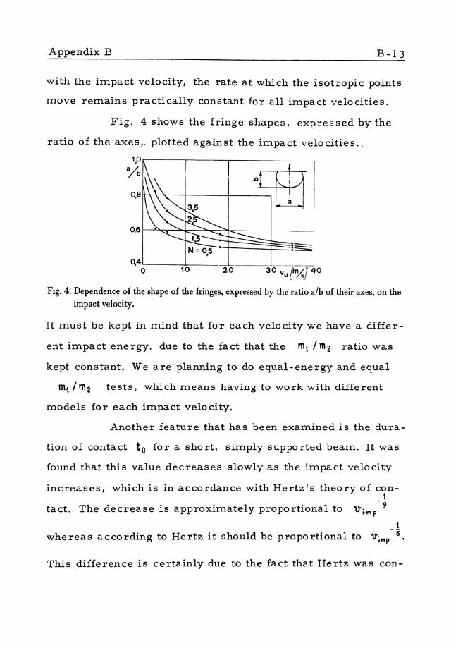
Appendix B B-13
with the impact velocity, the rate at which the isotropic points
move remains practically constant for all impact velocities.
Fig. 4 shows the fringe shapes, expres sed by the
ratio of the axes,. plotted ag~inst the impact velocities ..
0,4'---__ ~=--_ o 10
Fig. 4. Dependence of the shape of the fringes, expressed by the ratio alb of their axes, on the impact velocity.
It must be kept in mind that for each velocity we have a differ
ent impact energy, due to the fact that the mi 1m2 ratio was
kept constant. We are planning to do equal-energy and equal
mi 1m2 tests, which means having to work with different
models for each impact velocity.
Another feature that has been examined is the dura-
tion of contact to for a short, simply supported beam. It was
found that this value decreases slowly as the impact velocity
increases, which is in accordance with Hertz's theory of cont
tact. The decrease is approximately proportional to 'I)'~trlp-9 1
whereas according to Hertz it should be proportional to '\t~IIIP - 5.
This difference is certainly due to the fact that Hertz was con-

B-14 M. Tschinke
side ring a perfectly elastic material.
Betser and Frocht [8] working with a higher -mo-
dulus material, Castolite, have found that in similar conditions
the duration of impact does not change for different impact vel
ocities. This is in accordance with the elementary theory of
De St. Venant and Flamant for long beams. 1,0
alb
0,8
0,6
0,4 o
Vu = 2,9 m,../s
vu=35 m/s 1---'
,
_2 .... ~ __ --------- , -.' -1,5 _---e- -------e , , -, .' -- ---~::
:...--; ---- -.- ~===-" 2,5 N =0,5 ~15 ,
0,5
Q,25 Q,50 t [msJ 0,75
Fig. 5. Values of the ratio alb Vs. time for two different impact velocities.
to fJ 2. 6
[ ms] 2 -. to --- • _____
t:::----:::::: f:I • '""" 5
-..::::::. --.--I • 21 48
Fig. 6. Duratioll of impact (to) and time lapse (\) between the beginning of the impact and the occurt'm't' of the maximum fringe order, shown Vs. the impact velocity.

B-15
References
[1] Kuske, A. : "Contributo allo studio della propaga-zione di stati di tensione con l'ausilio del procediITlento fotoe1astico" Paper given at the "SeITlinario suI teITla ''Analisi speriITlentale delle tensioni nei recipienti a pressione", Bologna, Faculty of Engineering, September 15-18, 1970;
[2] Manzella, G. : "Fattori di concentrazione delle ten-sioni e coefficienti di forITla per aste forate soggette ad urto trasversale". Tecnica Italiana, Anno XXIX, No.4, Aprile 1964;
[31 Kuske, A. : "Photoelastic research on dynaITlic stresses" SESA, Vol. XXIII, No.1, p. 105;
[4J Meyer, M. L. ; NagaITlati, G.; Taylor, D. A. W. :"Notes on photoelastic observations of iITlpact phenomena", Post-graduate Dept. ()f Applied Mechanics, Sheffields University;
[5] Tschinke, M. : "Urto trasversale su travi corte"; Disegno di Macchine, Palermo, No.1, 1969;
[6] Dally, J. W. ; Riley, W. F. ; Durelli, A. J. : "A photo-elastic approach to transient stresses problems employing low-ITlodulus materials". ASME Paper No. 59-A-IO;

B-16 M. Tschinke
[7] Durelli, A. J.; Riley, W. F. "Introduction to photo-me chani cs " Prentice-Hall Inc. Englewood Cliffs, N.J. 1965;
[8J Betser, A. A. ; Frocht, M. M. : "A photoelastic study of maximum tensile stresses in simply supported short beams under central transverse impact" . AS ME Paper No. 57-APM-36.


![link.springer.com978-1-4020-9043-1/1.pdf · References There are three journals containing many of the references: [1] Doklady Akad. Nauk SSSR = Reports of the USSR Academy of Sciences.](https://static.fdocuments.net/doc/165x107/5ffe5796c0c32126b744b6ac/link-978-1-4020-9043-11pdf-references-there-are-three-journals-containing-many.jpg)


