
Reference Handbook
50
DEIF A/S Multi-instrument MIB 7000/7000C/7020 4189320016B (UK) Installation Instructions and Reference Handbook • Product information • Installation instructions • Basic operation DEIF A/S, Frisenborgvej 33 Tel.: +45 9614 9614, Fax: +45 9614 9615 DK-7800 Skive, Denmark E-mail: [email protected], URL: www.deif.com
Transcript of Reference Handbook
DEI
F A
/S
Multi-instrument MIB 7000/7000C/7020 4189320016B (UK)
Installation Instructions and Reference Handbook
• Product information • Installation instructions
• Basic operation
DEIF A/S, Frisenborgvej 33 Tel.: +45 9614 9614, Fax: +45 9614 9615 DK-7800 Skive, Denmark E-mail: [email protected], URL: www.deif.com
MIB Installation Instructions and Reference Handbook
DEIF A/S Page 2 of 50
Table of contents
1. ABOUT THIS DOCUMENT........................................................ 3 GENERAL PURPOSE............................................................................... 3 INTENDED USERS .................................................................................. 3 CONTENTS/OVERALL STRUCTURE .......................................................... 3
2. WARNINGS AND LEGAL INFORMATION ............................... 5 LEGAL INFORMATION AND RESPONSIBILITY............................................. 5 ELECTROSTATIC DISCHARGE AWARENESS ............................................. 5 SAFETY ISSUES..................................................................................... 5 CE-MARKING......................................................................................... 5 DEFINITIONS ......................................................................................... 6
3. PRODUCT INFORMATION........................................................ 7 DESCRIPTION OF FUNCTIONS................................................................. 7 MEASURED AND CALCULATED VALUES ................................................... 8
4. INSTALLATION INSTRUCTIONS ........................................... 10 ELECTRICAL CONNECTION ................................................................... 12 AUXILIARY POWER SUPPLY .................................................................. 14 MEASURING CONNECTIONS ................................................................. 15 MOST USED WIRING METHOD............................................................... 21 DIGITAL OUTPUT (ONLY MIB 7020)...................................................... 25 COMMUNICATION................................................................................. 26 SYSTEM PARAMETER SETTING............................................................. 27
5. BASIC OPERATION................................................................. 41 DISPLAY.............................................................................................. 41 DISPLAY MENUS .................................................................................. 43 VOLTAGE AND CURRENT DATA ............................................................. 43 POWER RELATED DATA........................................................................ 44 ENERGY AND RUNNING HOUR COUNTERS............................................. 46 POWER QUALITY DATA......................................................................... 47 STATISTICS DATA ................................................................................ 48
MIB Installation Instructions and Reference Handbook
DEIF A/S Page 3 of 50
1. About this document This chapter includes general user information about this handbook concerning the general purpose, the intended users and the overall contents and structure.
General purpose This document is the Installation Instructions and Reference Handbook for DEIF’s multi-instrument, the MIB. The document mainly includes installation instructions, general product information and information about basic, daily operation. The general purpose of the Installation Instructions and Reference Handbook is to provide the information needed to install the unit correctly and to provide information about the basic functionality of the instrument.
Intended users The handbook is mainly intended for the person responsible for the installation and setup of the instrument. On the basis of this document the operator will be able to use the multi-instrument for simple, daily operation.
Contents/overall structure This handbook is divided into chapters and in order to make the structure of the document simple and easy to use, each chapter will begin from the top of a new page. The following will outline the contents of each of the chapters.
About this document This first chapter includes general information about this handbook as a document. It deals with the general purpose and the intended users of the document. Furthermore, it outlines the overall contents and structure.
Warnings and legal information The second chapter includes information about general legal issues and safety precautions relevant in the handling of DEIF products. Furthermore, this chapter will introduce note and warning symbols.
Please make sure to read this handbook before working with the instrument. Failure to do this could result in human injury or damage to the equipment.
MIB Installation Instructions and Reference Handbook
DEIF A/S Page 4 of 50
Product information The third chapter will deal with the unit in general and describe its functions.
Installation instructions Fourth chapter includes the information needed to perform correct installation of the instrument, e.g. mounting instructions, terminals, wiring, inputs, parameter setting etc.
Basic operation Fifth chapter deals with the basic operation of the MIB. Screen dumps are used in order to simplify the information.
MIB Installation Instructions and Reference Handbook
DEIF A/S Page 5 of 50
2. Warnings and legal information This chapter includes important information about general legal issues relevant in the handling of DEIF products. Furthermore, some overall safety precautions will be introduced and recommended. Finally, the highlighted notes and warnings, which will be used throughout the document, are presented.
Legal information and responsibility DEIF takes no responsibility for installation or operation of the instrument. If there is any doubt about how to install or operate the instrument, the company responsible for the installation or the operation of the instrument must be contacted.
Electrostatic discharge awareness Sufficient care must be taken to protect the terminals against static discharges during the installation. Once the unit is installed and connected, these precautions are no longer necessary.
Safety issues Installing the unit implies work with dangerous currents and voltages. Therefore, the installation should only be carried out by authorised personnel who understand the risks involved in working with live electrical equipment.
CE-marking The MIB is CE-marked according to the EMC directive for industrial environments, which normally covers the most common use of the product.
The units are not to be opened by unauthorised personnel. If opened anyway, the warranty will be lost.
Be aware of the hazardous live currents and voltages. Do not touch any AC measurement inputs as this could lead to injury or death.
MIB Installation Instructions and Reference Handbook
DEIF A/S Page 6 of 50
Definitions Throughout this document a number of notes and warnings will be presented. To ensure that these are noticed, they will be highlighted in order to separate them from the general text.
Notes
Warnings
The warnings indicate a potentially dangerous situation, which could result in death, personal injury or damaged equipment, if certain guidelines are not followed.
The notes provide general information, which will be helpful for the reader to bear in mind.
MIB Installation Instructions and Reference Handbook
DEIF A/S Page 7 of 50
3. Product information This chapter includes overall product information about the unit.
Description of functions The multi-instrument MIB is a microprocessor-based measuring unit providing measurement of all electrical quantities on a 1- or 3-phase electric energy distribution network. The measurements are shown on the built-in display. Measures true RMS values on all 1- or 3-phase network topologies with or without neutral and with both balanced and unbalanced load. The MIB can replace a large number of standard analogue instruments in all electrical measuring applications. It contains all necessary measuring circuits and presents all values on a display with white backlight. The display has 4 digits resolution for all measurements. The backlight on-time is selectable. MIB is a flexible measuring unit that enables the user to easily adapt the instrument to the individual application. Counter reset and change of the instrument settings can be password protected. The product family includes three versions:
• MIB 7000: Basic version • MIB 7000C: Basic version + communication • MIB 7020: Basic version + 2 digital outputs
MIB Installation Instructions and Reference Handbook
DEIF A/S Page 8 of 50
Measured and calculated values
Voltage Actual voltage of each phase-phase and phase-neutral.
Current Actual current of each phase and neutral current.
Active power (P) Active power of each phase.
Reactive power (Q) Reactive power of each phase.
Apparent power (S) Total apparent power. Demand Demand of each phase current, active power and reactive power. Power factor (PF) Power factor of each phase and total power factor.
Frequency Actual frequency of L1. Digital outputs DO (only MIB 7020) For alarm output or energy pulse output. Min./max. Min./max. of demand, voltage, current and active/reactive power. Energy pulse output (only MIB 7020) Energy pulse output (assign to import/export of real and reactive energy). THD (up to 15th harmonics) Voltage/current THD of each phase. Energy Import and export of energy, inductive and capacitive of reactive energy.
MIB Installation Instructions and Reference Handbook
DEIF A/S Page 9 of 50
Alarm Alarm can be related to any metering parameters (see “Digital output” on page 39). Running hour Meters the duration of the operation. Unbalance factor Voltage and current.
MIB Installation Instructions and Reference Handbook
DEIF A/S Page 10 of 50
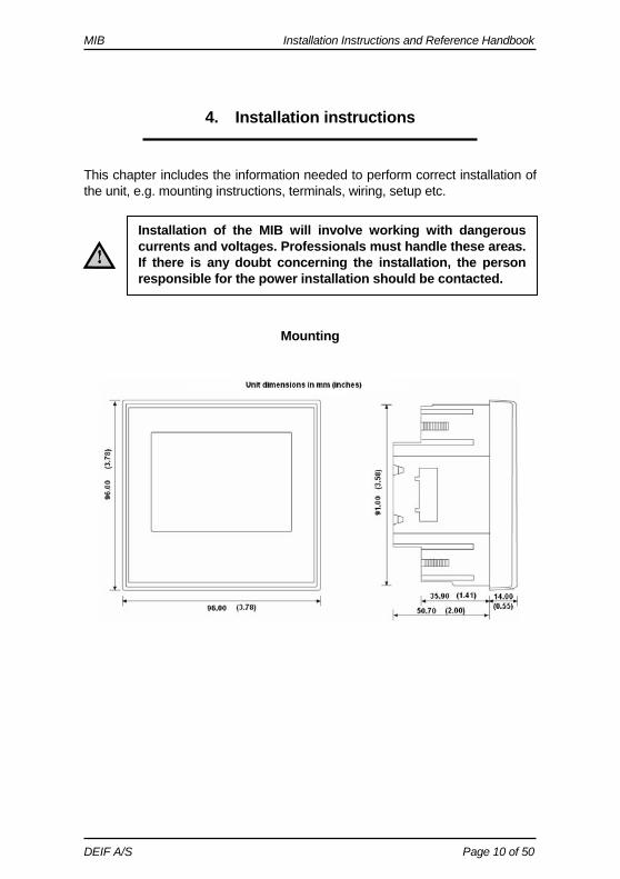
4. Installation instructions This chapter includes the information needed to perform correct installation of the unit, e.g. mounting instructions, terminals, wiring, setup etc.
Mounting
Unit dimensions in mm
Installation of the MIB will involve working with dangerous currents and voltages. Professionals must handle these areas. If there is any doubt concerning the installation, the person responsible for the power installation should be contacted.
MIB Installation Instructions and Reference Handbook
DEIF A/S Page 11 of 50
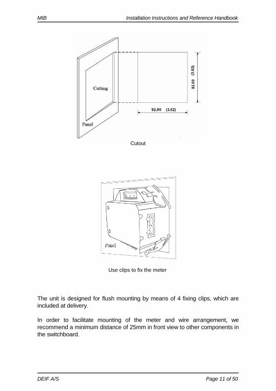
Cutout
Use clips to fix the meter
The unit is designed for flush mounting by means of 4 fixing clips, which are included at delivery. In order to facilitate mounting of the meter and wire arrangement, we recommend a minimum distance of 25mm in front view to other components in the switchboard.
MIB Installation Instructions and Reference Handbook
DEIF A/S Page 12 of 50
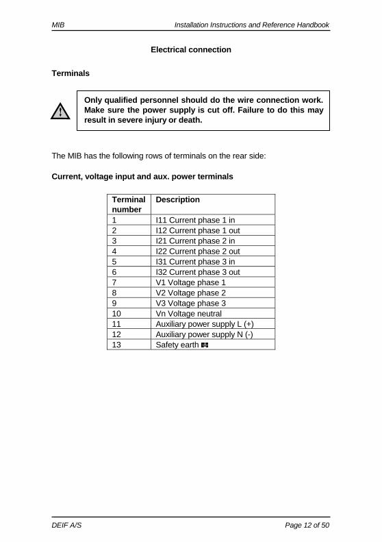
Electrical connection
Terminals The MIB has the following rows of terminals on the rear side:
Current, voltage input and aux. power terminals
Terminal number
Description
1 I11 Current phase 1 in 2 I12 Current phase 1 out 3 I21 Current phase 2 in 4 I22 Current phase 2 out 5 I31 Current phase 3 in 6 I32 Current phase 3 out 7 V1 Voltage phase 1 8 V2 Voltage phase 2 9 V3 Voltage phase 3 10 Vn Voltage neutral 11 Auxiliary power supply L (+) 12 Auxiliary power supply N (-) 13 Safety earth
Only qualified personnel should do the wire connection work. Make sure the power supply is cut off. Failure to do this may result in severe injury or death.
MIB Installation Instructions and Reference Handbook
DEIF A/S Page 13 of 50
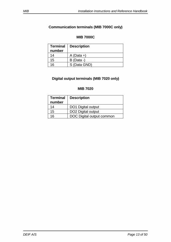
Communication terminals (MIB 7000C only)
MIB 7000C
Terminal number
Description
14 A (Data +) 15 B (Data -) 16 S (Data GND)
Digital output terminals (MIB 7020 only)
MIB 7020
Terminal number
Description
14 DO1 Digital output 15 DO2 Digital output 16 DOC Digital output common
MIB Installation Instructions and Reference Handbook
DEIF A/S Page 14 of 50
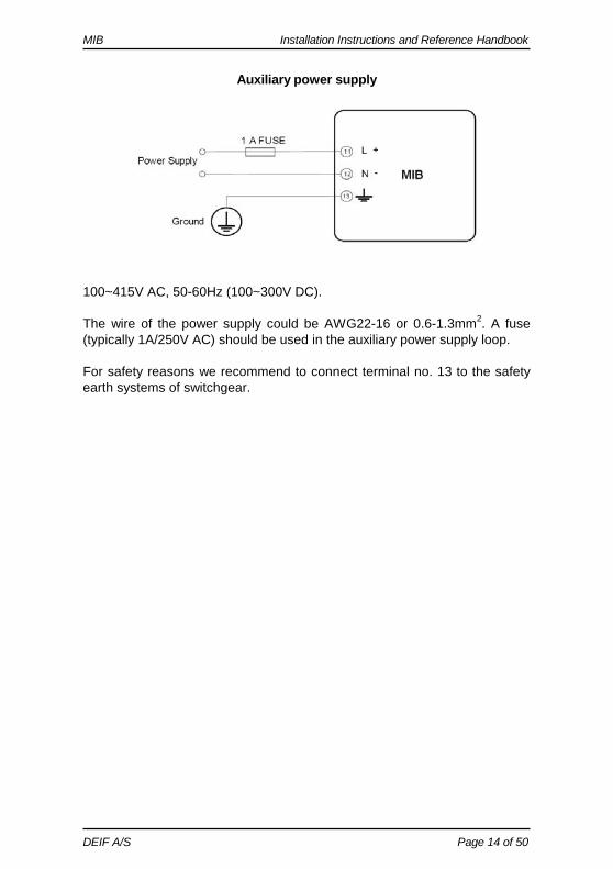
Auxiliary power supply
100~415V AC, 50-60Hz (100~300V DC). The wire of the power supply could be AWG22-16 or 0.6-1.3mm2. A fuse (typically 1A/250V AC) should be used in the auxiliary power supply loop. For safety reasons we recommend to connect terminal no. 13 to the safety earth systems of switchgear.
MIB Installation Instructions and Reference Handbook
DEIF A/S Page 15 of 50
Measuring connections The MIB can be used in almost all kinds of 3-phase connections. The voltage and current input wiring modes can be set separately in the parameter setting process. The voltage wiring mode can be:
The rated measuring voltage of the MIB is 400 LN and 690V LL. Naturally, the instrument can be used in systems with lower system voltage level, e.g. in connection with 100V volt-age transformers. The measuring accuracy will in this case be slightly reduced. The voltage range of PT1 is 50-1.000.000V.
Voltage inputs
• 3LN: 3-phase 4-line Y • 2LN: 3-phase 4-line Y with 2 voltage transformers • 1LN: 1-phase 2-line • 3LL: 3-phase 3-line direct connection • 2LL: 3-line open delta
The MIB is designed to be used together with current trans-formers with secondary output of 5A. If the secondary cur-rent is 1A, the primary ratio has to be multiplied with 5 to give a correct reading. Example: 500/1 = 2500/5. Max. transformer ratio: 50000/5 or 10000/1.
Current inputs
• 3CT • 2CT • 1CT
Any voltage mode can be grouped with any of the current modes.
The wire of the measuring inputs supply should be 1.5-5mm² (AWG10-16). The voltage measuring inputs should be pro-tected by fuses (1A/250V AC).
MIB Installation Instructions and Reference Handbook
DEIF A/S Page 16 of 50
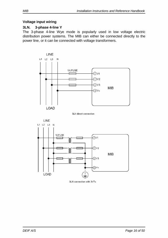
Voltage input wiring 3LN. 3-phase 4-line Y The 3-phase 4-line Wye mode is popularly used in low voltage electric distribution power systems. The MIB can either be connected directly to the power line, or it can be connected with voltage transformers.
MIB Installation Instructions and Reference Handbook
DEIF A/S Page 17 of 50
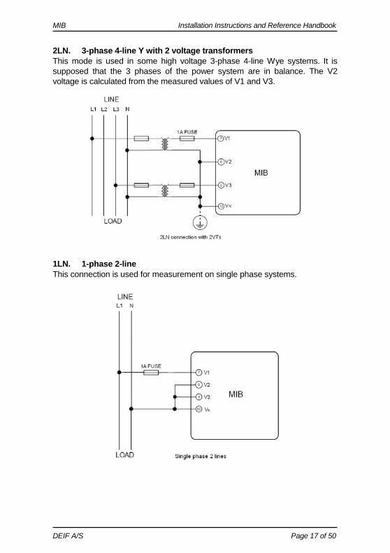
2LN. 3-phase 4-line Y with 2 voltage transformers This mode is used in some high voltage 3-phase 4-line Wye systems. It is supposed that the 3 phases of the power system are in balance. The V2 voltage is calculated from the measured values of V1 and V3.
1LN. 1-phase 2-line This connection is used for measurement on single phase systems.
MIB Installation Instructions and Reference Handbook
DEIF A/S Page 18 of 50
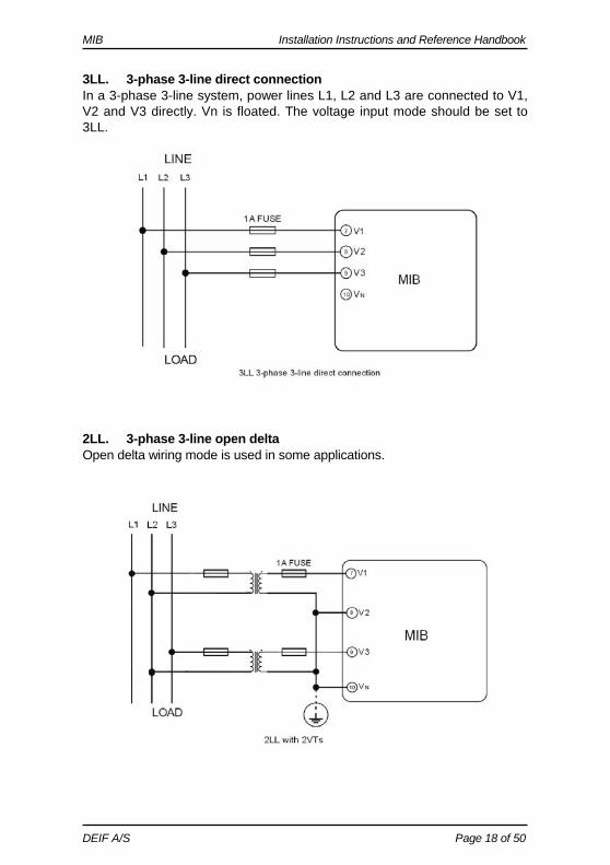
3LL. 3-phase 3-line direct connection In a 3-phase 3-line system, power lines L1, L2 and L3 are connected to V1, V2 and V3 directly. Vn is floated. The voltage input mode should be set to 3LL.
2LL. 3-phase 3-line open delta Open delta wiring mode is used in some applications.
MIB Installation Instructions and Reference Handbook
DEIF A/S Page 19 of 50
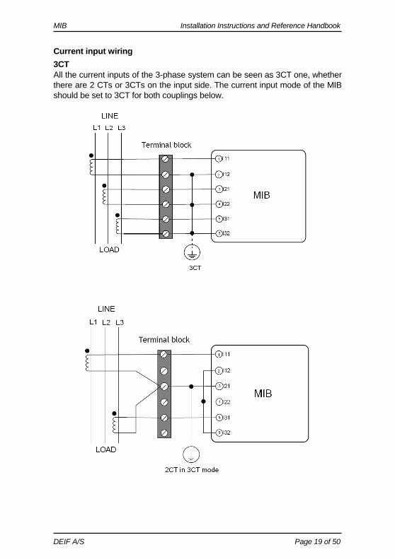
Current input wiring 3CT All the current inputs of the 3-phase system can be seen as 3CT one, whether there are 2 CTs or 3CTs on the input side. The current input mode of the MIB should be set to 3CT for both couplings below.
MIB Installation Instructions and Reference Handbook
DEIF A/S Page 20 of 50
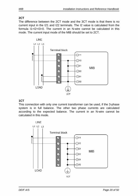
2CT The difference between the 2CT mode and the 3CT mode is that there is no current input in the I21 and I22 terminals. The I2 value is calculated from the formula I1+I2+I3=0. The current in an N-wire cannot be calculated in this mode. The current input mode of the MIB should be set to 2CT.
1CT This connection with only one current transformer can be used, if the 3-phase system is in full balance. The other two phase currents are calculated according to the expected balance. The current in an N-wire cannot be calculated in this mode.
MIB Installation Instructions and Reference Handbook
DEIF A/S Page 21 of 50
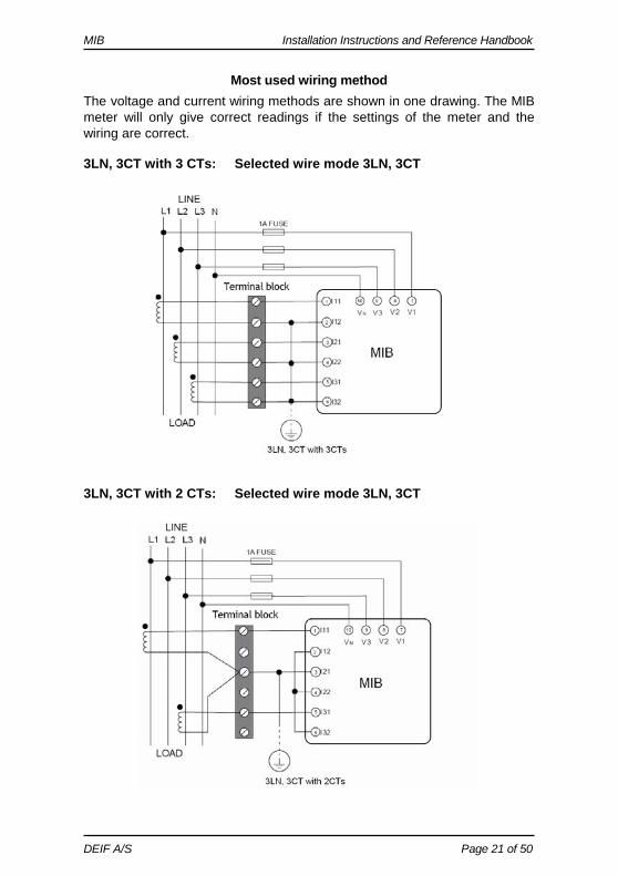
Most used wiring method The voltage and current wiring methods are shown in one drawing. The MIB meter will only give correct readings if the settings of the meter and the wiring are correct. 3LN, 3CT with 3 CTs: Selected wire mode 3LN, 3CT
3LN, 3CT with 2 CTs: Selected wire mode 3LN, 3CT
MIB Installation Instructions and Reference Handbook
DEIF A/S Page 22 of 50
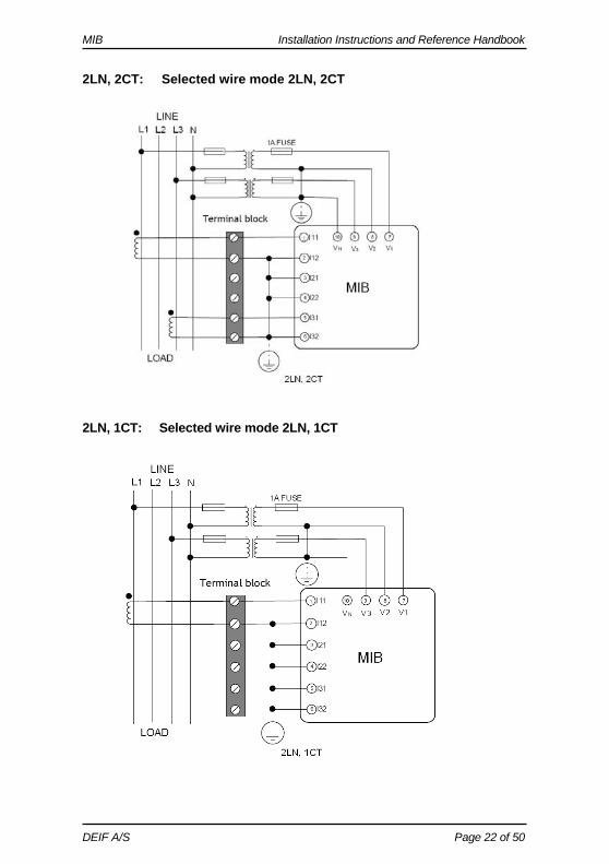
2LN, 2CT: Selected wire mode 2LN, 2CT
2LN, 1CT: Selected wire mode 2LN, 1CT
MIB Installation Instructions and Reference Handbook
DEIF A/S Page 23 of 50
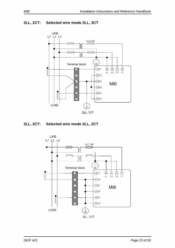
2LL, 2CT: Selected wire mode 2LL, 3CT
2LL, 2CT: Selected wire mode 2LL, 2CT
MIB Installation Instructions and Reference Handbook
DEIF A/S Page 24 of 50
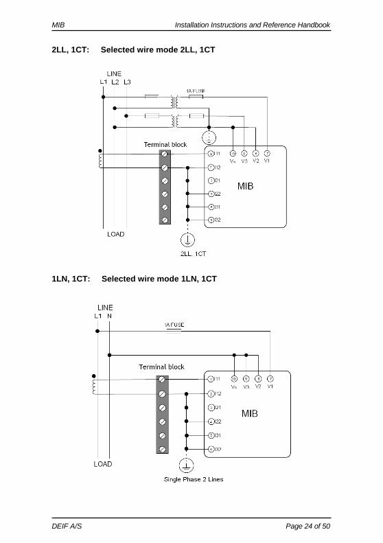
2LL, 1CT: Selected wire mode 2LL, 1CT 1LN, 1CT: Selected wire mode 1LN, 1CT
MIB Installation Instructions and Reference Handbook
DEIF A/S Page 25 of 50
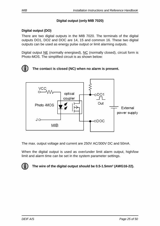
Digital output (only MIB 7020)
Digital output (DO) There are two digital outputs in the MIB 7020. The terminals of the digital outputs DO1, DO2 and DOC are 14, 15 and common 16. These two digital outputs can be used as energy pulse output or limit alarming outputs. Digital output NE (normally energised), NC (normally closed), circuit form is Photo-MOS. The simplified circuit is as shown below:
The contact is closed (NC) when no alarm is present.
The max. output voltage and current are 250V AC/300V DC and 50mA. When the digital output is used as over/under limit alarm output, high/low limit and alarm time can be set in the system parameter settings.
The wire of the digital output should be 0.5-1.5mm² (AWG16-22).
MIB Installation Instructions and Reference Handbook
DEIF A/S Page 26 of 50
Communication The communication port and protocol are RS485 and Modbus RTU. The terminals are A, B and S (14, 15, 16). A is differential data signal +, B is differential data signal and S is connected to a shield of twisted pair cables. The unit can handle up to 32 devices on the RS485 bus. The maximum connection length is 1000m. Conductors A and B should be terminated with a 120Ω terminating resistor at the end of the string. The MIB 7000C operates as slave unit, and the master unit is normally a PC, PLC or a data collector of RTU. The communications port of the master unit must have RS485 port.
Use shielded twisted pair of cable AWG22 (0.6mm2). The shield of the RS485 cable must be connected to the ground at one end only.
USB/RS485 or RS232/RS485 converter can be used to convert signal for PC.
MIB Installation Instructions and Reference Handbook
DEIF A/S Page 27 of 50
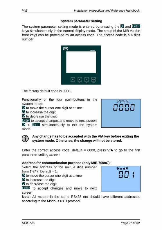
System parameter setting The system parameter setting mode is entered by pressing the and keys simultaneously in the normal display mode. The setup of the MIB via the front keys can be protected by an access code. The access code is a 4 digit number.
The factory default code is 0000. Functionality of the four push-buttons in the system mode:
to move the cursor one digit at a time to increase the digit to decrease the digit
to accept changes and move to next screen + simultaneously to exit the system
mode Enter the correct access code, default = 0000, press V/A to go to the first parameter setting screen. Address for communication purpose (only MIB 7000C): Select the address of the unit, a digit number from 1-247. Default = 1.
to move the cursor one digit at a time to increase the digit to decrease the digit
to accept changes and move to next screen Note: All meters in the same RS485 net should have different addresses according to the Modbus RTU protocol.
Any change has to be accepted with the V/A key before exiting the system mode. Otherwise, the change will not be stored.
MIB Installation Instructions and Reference Handbook
DEIF A/S Page 28 of 50
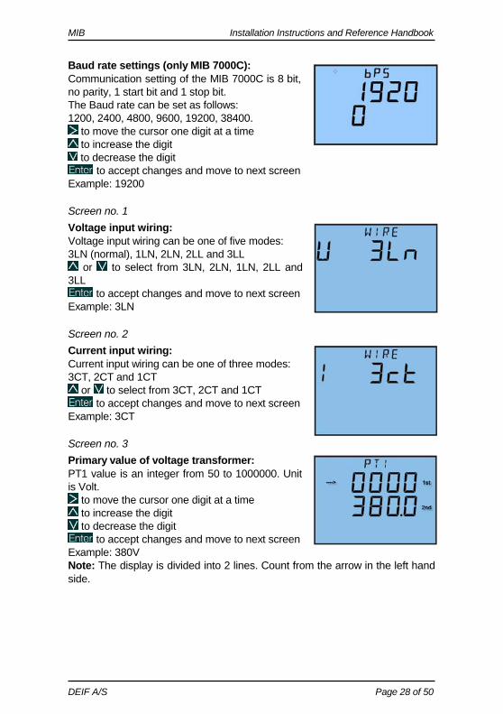
Baud rate settings (only MIB 7000C): Communication setting of the MIB 7000C is 8 bit, no parity, 1 start bit and 1 stop bit. The Baud rate can be set as follows: 1200, 2400, 4800, 9600, 19200, 38400.
to move the cursor one digit at a time to increase the digit to decrease the digit
to accept changes and move to next screen Example: 19200
Screen no. 1 Voltage input wiring: Voltage input wiring can be one of five modes: 3LN (normal), 1LN, 2LN, 2LL and 3LL
or to select from 3LN, 2LN, 1LN, 2LL and 3LL
to accept changes and move to next screen Example: 3LN
Screen no. 2 Current input wiring: Current input wiring can be one of three modes: 3CT, 2CT and 1CT
or to select from 3CT, 2CT and 1CT to accept changes and move to next screen
Example: 3CT
Screen no. 3 Primary value of voltage transformer: PT1 value is an integer from 50 to 1000000. Unit is Volt.
to move the cursor one digit at a time to increase the digit to decrease the digit
to accept changes and move to next screen Example: 380V Note: The display is divided into 2 lines. Count from the arrow in the left hand side.
MIB Installation Instructions and Reference Handbook
DEIF A/S Page 29 of 50
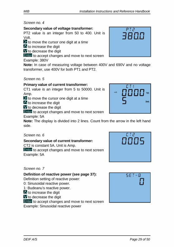
Screen no. 4 Secondary value of voltage transformer: PT2 value is an integer from 50 to 400. Unit is Volt.
to move the cursor one digit at a time to increase the digit to decrease the digit
to accept changes and move to next screen Example: 380V Note: In case of measuring voltage between 400V and 690V and no voltage transformer, use 400V for both PT1 and PT2.
Screen no. 5 Primary value of current transformer: CT1 value is an integer from 5 to 50000. Unit is Amp.
to move the cursor one digit at a time to increase the digit to decrease the digit
to accept changes and move to next screen Example: 5A Note: The display is divided into 2 lines. Count from the arrow in the left hand side.
Screen no. 6 Secondary value of current transformer: CT2 is constant 5A. Unit is Amp.
to accept changes and move to next screen Example: 5A
Screen no. 7 Definition of reactive power (see page 37): Definition setting of reactive power: 0: Sinusoidal reactive power. 1: Budeanu’s reactive power.
to increase the digit to decrease the digit
to accept changes and move to next screen Example: Sinusoidal reactive power
MIB Installation Instructions and Reference Handbook
DEIF A/S Page 30 of 50
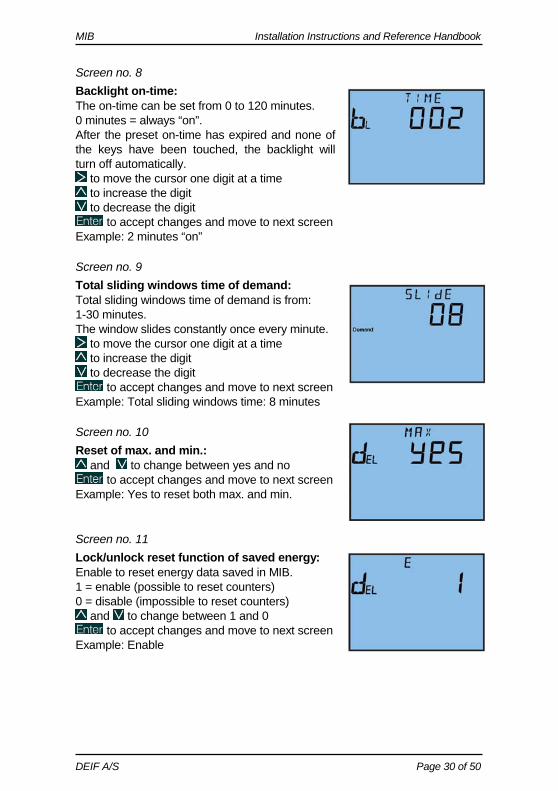
Screen no. 8 Backlight on-time: The on-time can be set from 0 to 120 minutes. 0 minutes = always “on”. After the preset on-time has expired and none of the keys have been touched, the backlight will turn off automatically.
to move the cursor one digit at a time to increase the digit to decrease the digit
to accept changes and move to next screen Example: 2 minutes “on”
Screen no. 9 Total sliding windows time of demand: Total sliding windows time of demand is from: 1-30 minutes. The window slides constantly once every minute.
to move the cursor one digit at a time to increase the digit to decrease the digit
to accept changes and move to next screen Example: Total sliding windows time: 8 minutes
Screen no. 10 Reset of max. and min.:
and to change between yes and no to accept changes and move to next screen
Example: Yes to reset both max. and min.
Screen no. 11 Lock/unlock reset function of saved energy: Enable to reset energy data saved in MIB. 1 = enable (possible to reset counters) 0 = disable (impossible to reset counters)
and to change between 1 and 0 to accept changes and move to next screen
Example: Enable
MIB Installation Instructions and Reference Handbook
DEIF A/S Page 31 of 50
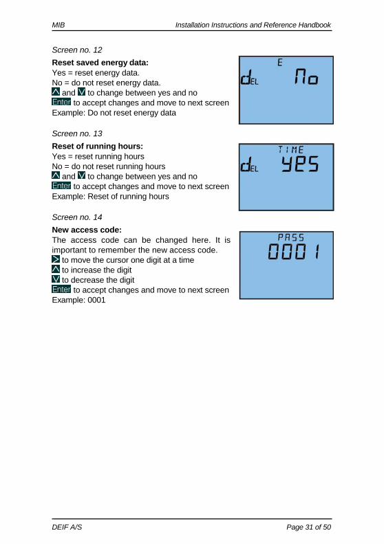
Screen no. 12 Reset saved energy data: Yes = reset energy data. No = do not reset energy data.
and to change between yes and no to accept changes and move to next screen
Example: Do not reset energy data
Screen no. 13 Reset of running hours: Yes = reset running hours No = do not reset running hours
and to change between yes and no to accept changes and move to next screen
Example: Reset of running hours
Screen no. 14 New access code: The access code can be changed here. It is important to remember the new access code.
to move the cursor one digit at a time to increase the digit to decrease the digit
to accept changes and move to next screen Example: 0001
MIB Installation Instructions and Reference Handbook
DEIF A/S Page 32 of 50
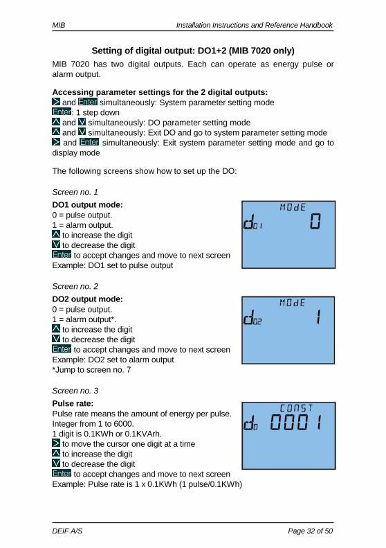
Setting of digital output: DO1+2 (MIB 7020 only) MIB 7020 has two digital outputs. Each can operate as energy pulse or alarm output. Accessing parameter settings for the 2 digital outputs:
and simultaneously: System parameter setting mode : 1 step down
and simultaneously: DO parameter setting mode and simultaneously: Exit DO and go to system parameter setting mode and simultaneously: Exit system parameter setting mode and go to
display mode The following screens show how to set up the DO:
Screen no. 1 DO1 output mode: 0 = pulse output. 1 = alarm output.
to increase the digit to decrease the digit
to accept changes and move to next screen Example: DO1 set to pulse output
Screen no. 2 DO2 output mode: 0 = pulse output. 1 = alarm output*.
to increase the digit to decrease the digit
to accept changes and move to next screen Example: DO2 set to alarm output *Jump to screen no. 7
Screen no. 3 Pulse rate: Pulse rate means the amount of energy per pulse. Integer from 1 to 6000. 1 digit is 0.1KWh or 0.1KVArh.
to move the cursor one digit at a time to increase the digit to decrease the digit
to accept changes and move to next screen Example: Pulse rate is 1 x 0.1KWh (1 pulse/0.1KWh)
MIB Installation Instructions and Reference Handbook
DEIF A/S Page 33 of 50
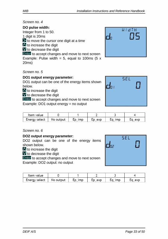
Screen no. 4 DO pulse width: Integer from 1 to 50. 1 digit is 20ms
to move the cursor one digit at a time to increase the digit to decrease the digit
to accept changes and move to next screen Example: Pulse width = 5, equal to 100ms (5 x 20ms)
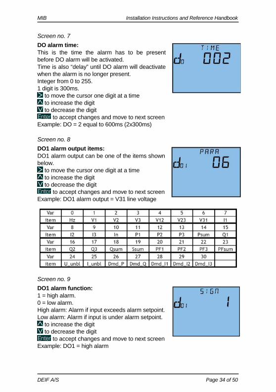
Screen no. 5 DO1 output energy parameter: DO1 output can be one of the energy items shown below.
to increase the digit to decrease the digit
to accept changes and move to next screen Example: DO1 output energy = no output
Screen no. 6 DO2 output energy parameter: DO2 output can be one of the energy items shown below.
to increase the digit to decrease the digit
to accept changes and move to next screen Example: DO2 output: no output
MIB Installation Instructions and Reference Handbook
DEIF A/S Page 34 of 50
Screen no. 7 DO alarm time: This is the time the alarm has to be present before DO alarm will be activated. Time is also “delay” until DO alarm will deactivate when the alarm is no longer present. Integer from 0 to 255. 1 digit is 300ms.
to move the cursor one digit at a time to increase the digit to decrease the digit
to accept changes and move to next screen Example: DO = 2 equal to 600ms (2x300ms)
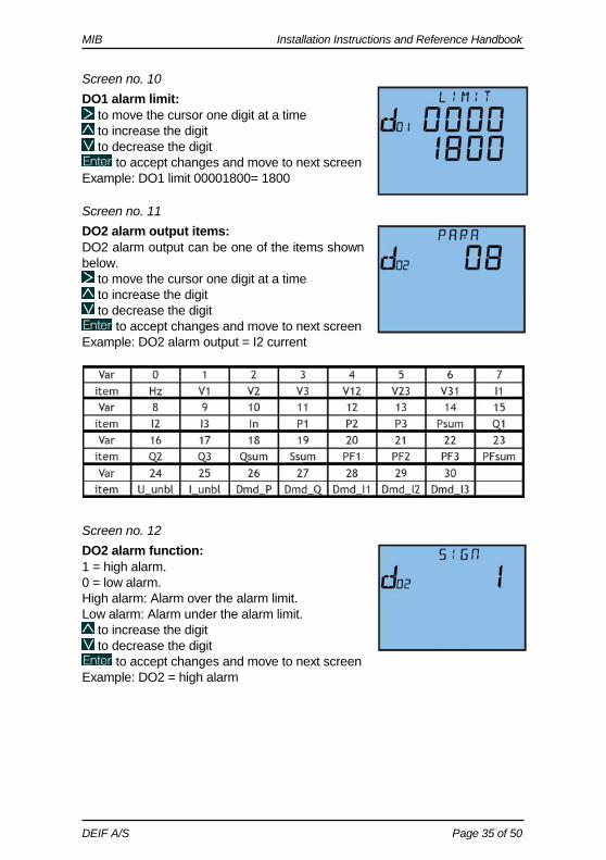
Screen no. 8 DO1 alarm output items: DO1 alarm output can be one of the items shown below.
to move the cursor one digit at a time to increase the digit to decrease the digit
to accept changes and move to next screen Example: DO1 alarm output = V31 line voltage
Screen no. 9 DO1 alarm function: 1 = high alarm. 0 = low alarm. High alarm: Alarm if input exceeds alarm setpoint. Low alarm: Alarm if input is under alarm setpoint.
to increase the digit to decrease the digit
to accept changes and move to next screen Example: DO1 = high alarm
MIB Installation Instructions and Reference Handbook
DEIF A/S Page 35 of 50
Screen no. 10 DO1 alarm limit:
to move the cursor one digit at a time to increase the digit to decrease the digit
to accept changes and move to next screen Example: DO1 limit 00001800= 1800
Screen no. 11 DO2 alarm output items: DO2 alarm output can be one of the items shown below.
to move the cursor one digit at a time to increase the digit to decrease the digit
to accept changes and move to next screen Example: DO2 alarm output = I2 current
Screen no. 12 DO2 alarm function: 1 = high alarm. 0 = low alarm. High alarm: Alarm over the alarm limit. Low alarm: Alarm under the alarm limit.
to increase the digit to decrease the digit
to accept changes and move to next screen Example: DO2 = high alarm
MIB Installation Instructions and Reference Handbook
DEIF A/S Page 36 of 50
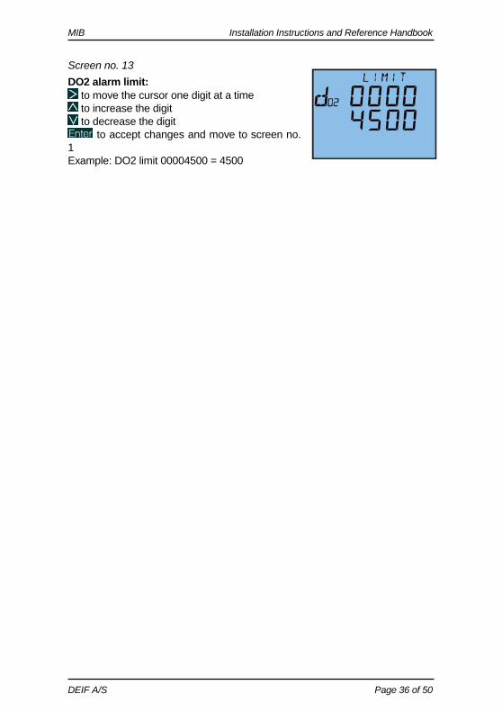
Screen no. 13 DO2 alarm limit:
to move the cursor one digit at a time to increase the digit to decrease the digit
to accept changes and move to screen no. 1 Example: DO2 limit 00004500 = 4500
MIB Installation Instructions and Reference Handbook
DEIF A/S Page 37 of 50
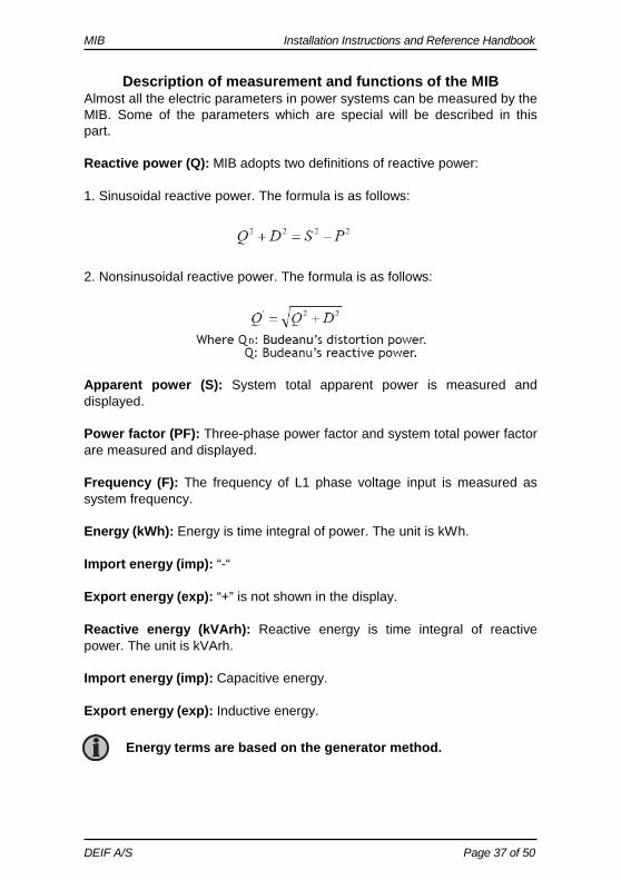
Description of measurement and functions of the MIB Almost all the electric parameters in power systems can be measured by the MIB. Some of the parameters which are special will be described in this part. Reactive power (Q): MIB adopts two definitions of reactive power: 1. Sinusoidal reactive power. The formula is as follows: 2. Nonsinusoidal reactive power. The formula is as follows:
Apparent power (S): System total apparent power is measured and displayed. Power factor (PF): Three-phase power factor and system total power factor are measured and displayed. Frequency (F): The frequency of L1 phase voltage input is measured as system frequency. Energy (kWh): Energy is time integral of power. The unit is kWh. Import energy (imp): “-“ Export energy (exp): “+” is not shown in the display. Reactive energy (kVArh): Reactive energy is time integral of reactive power. The unit is kVArh. Import energy (imp): Capacitive energy. Export energy (exp): Inductive energy.
Energy terms are based on the generator method.
MIB Installation Instructions and Reference Handbook
DEIF A/S Page 38 of 50
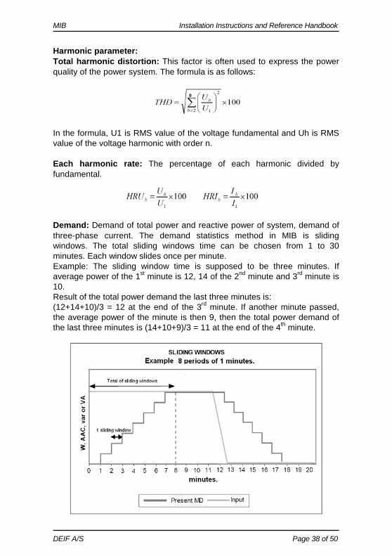
Harmonic parameter: Total harmonic distortion: This factor is often used to express the power quality of the power system. The formula is as follows:
In the formula, U1 is RMS value of the voltage fundamental and Uh is RMS value of the voltage harmonic with order n. Each harmonic rate: The percentage of each harmonic divided by fundamental.
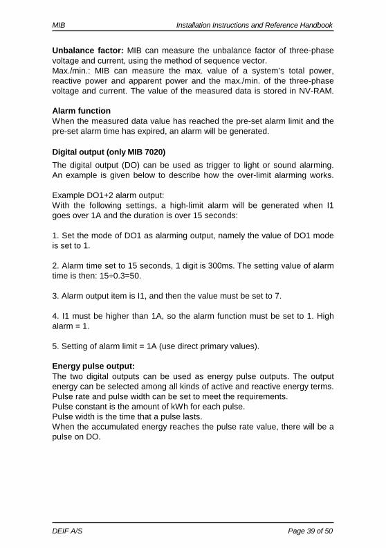
Demand: Demand of total power and reactive power of system, demand of three-phase current. The demand statistics method in MIB is sliding windows. The total sliding windows time can be chosen from 1 to 30 minutes. Each window slides once per minute. Example: The sliding window time is supposed to be three minutes. If average power of the 1st minute is 12, 14 of the 2nd minute and 3rd minute is 10. Result of the total power demand the last three minutes is: (12+14+10)/3 = 12 at the end of the 3rd minute. If another minute passed, the average power of the minute is then 9, then the total power demand of the last three minutes is (14+10+9)/3 = 11 at the end of the 4th minute.
MIB Installation Instructions and Reference Handbook
DEIF A/S Page 39 of 50
Unbalance factor: MIB can measure the unbalance factor of three-phase voltage and current, using the method of sequence vector. Max./min.: MIB can measure the max. value of a system’s total power, reactive power and apparent power and the max./min. of the three-phase voltage and current. The value of the measured data is stored in NV-RAM. Alarm function When the measured data value has reached the pre-set alarm limit and the pre-set alarm time has expired, an alarm will be generated.
Digital output (only MIB 7020) The digital output (DO) can be used as trigger to light or sound alarming. An example is given below to describe how the over-limit alarming works. Example DO1+2 alarm output: With the following settings, a high-limit alarm will be generated when I1 goes over 1A and the duration is over 15 seconds: 1. Set the mode of DO1 as alarming output, namely the value of DO1 mode is set to 1. 2. Alarm time set to 15 seconds, 1 digit is 300ms. The setting value of alarm time is then: 15÷0.3=50. 3. Alarm output item is I1, and then the value must be set to 7. 4. I1 must be higher than 1A, so the alarm function must be set to 1. High alarm = 1. 5. Setting of alarm limit = 1A (use direct primary values). Energy pulse output: The two digital outputs can be used as energy pulse outputs. The output energy can be selected among all kinds of active and reactive energy terms. Pulse rate and pulse width can be set to meet the requirements. Pulse constant is the amount of kWh for each pulse. Pulse width is the time that a pulse lasts. When the accumulated energy reaches the pulse rate value, there will be a pulse on DO.
MIB Installation Instructions and Reference Handbook
DEIF A/S Page 40 of 50
Related parameters: Pulse energy output ranges from 0 to 4 corresponding to none, Ep_imp, Ep_exp, Eq_imp, Eq_exp. Pulse rate ranges from 1 to 6000 (integer) with a unit of 0.1kWh (kVArh), apparently that is the resolving power of energy output. Pulse width ranges from 1 to 50 (integer) with a unit of 20ms. The narrowest interval between two pulses is 20ms. In practice, the pulse width and the pulse ratio are selected according to system power. The relation of the two parameters should satisfy the following expression:
Pulse rate >[(pulse width +1)×Pmax]÷18000 In the expression, the Pmax is the maximum power or reactive power. The unit is kW or kVAr. Recommended pulse rate is 3 to 5 times the right side value of the above expression.
MIB Installation Instructions and Reference Handbook
DEIF A/S Page 41 of 50
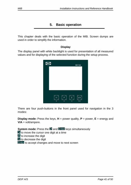
5. Basic operation This chapter deals with the basic operation of the MIB. Screen dumps are used in order to simplify the information.
Display The display panel with white backlight is used for presentation of all measured values and for displaying of the selected function during the setup process.
There are four push-buttons in the front panel used for navigation in the 3 modes: Display mode: Press the keys, H = power quality, P = power, E = energy and V/A = volt/ampere. System mode: Press the and keys simultaneously
to move the cursor one digit at a time to increase the digit to decrease the digit
to accept changes and move to next screen
MIB Installation Instructions and Reference Handbook
DEIF A/S Page 42 of 50
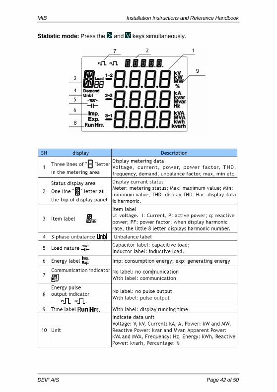
Statistic mode: Press the and keys simultaneously.
MIB Installation Instructions and Reference Handbook
DEIF A/S Page 43 of 50
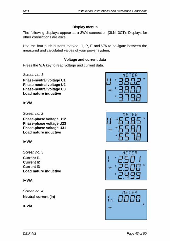
Display menus The following displays appear at a 3W4 connection (3LN, 3CT). Displays for other connections are alike. Use the four push-buttons marked, H, P, E and V/A to navigate between the measured and calculated values of your power system.
Voltage and current data Press the V/A key to read voltage and current data.
Screen no. 1 Phase-neutral voltage U1 Phase-neutral voltage U2 Phase-neutral voltage U3 Load nature inductive
V/A
Screen no. 2 Phase-phase voltage U12 Phase-phase voltage U23 Phase-phase voltage U31 Load nature inductive
V/A
Screen no. 3 Current I1 Current I2 Current I3 Load nature inductive
V/A
Screen no. 4 Neutral current (In)
V/A
MIB Installation Instructions and Reference Handbook
DEIF A/S Page 44 of 50
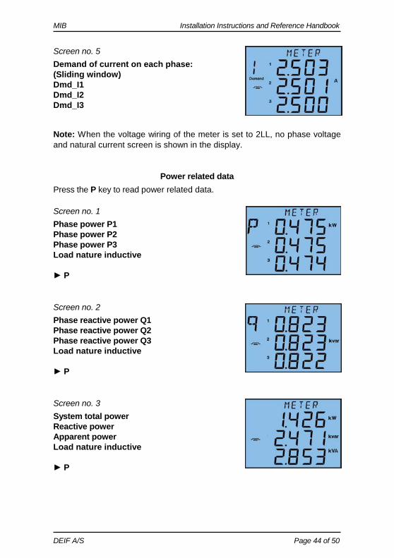
Screen no. 5 Demand of current on each phase: (Sliding window) Dmd_I1 Dmd_I2 Dmd_I3 Note: When the voltage wiring of the meter is set to 2LL, no phase voltage and natural current screen is shown in the display.
Power related data Press the P key to read power related data.
Screen no. 1 Phase power P1 Phase power P2 Phase power P3 Load nature inductive P
Screen no. 2 Phase reactive power Q1 Phase reactive power Q2 Phase reactive power Q3 Load nature inductive P
Screen no. 3 System total power Reactive power Apparent power Load nature inductive P
MIB Installation Instructions and Reference Handbook
DEIF A/S Page 45 of 50
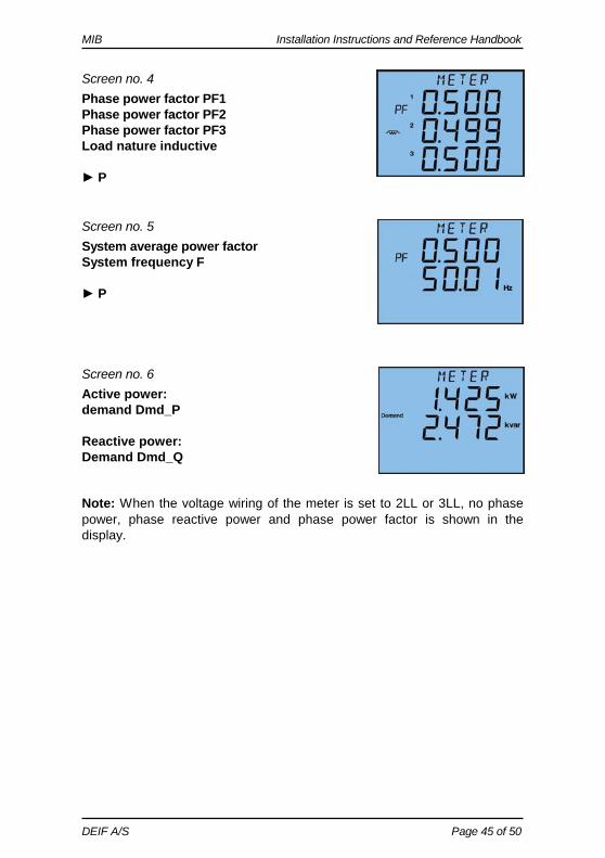
Screen no. 4 Phase power factor PF1 Phase power factor PF2 Phase power factor PF3 Load nature inductive P
Screen no. 5 System average power factor System frequency F P
Screen no. 6 Active power: demand Dmd_P Reactive power: Demand Dmd_Q Note: When the voltage wiring of the meter is set to 2LL or 3LL, no phase power, phase reactive power and phase power factor is shown in the display.
MIB Installation Instructions and Reference Handbook
DEIF A/S Page 46 of 50
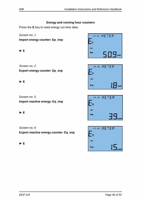
Energy and running hour counters Press the E key to read energy run time data.
Screen no. 1 Import energy counter: Ep_imp E
Screen no. 2 Export energy counter: Ep_exp E
Screen no. 5 Import reactive energy: Eq_imp E
Screen no. 6 Export reactive energy counter: Eq_exp E
MIB Installation Instructions and Reference Handbook
DEIF A/S Page 47 of 50
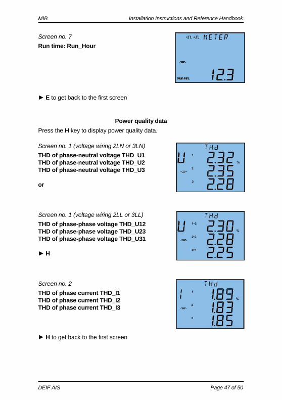
Screen no. 7 Run time: Run_Hour E to get back to the first screen
Power quality data Press the H key to display power quality data.
Screen no. 1 (voltage wiring 2LN or 3LN) THD of phase-neutral voltage THD_U1 THD of phase-neutral voltage THD_U2 THD of phase-neutral voltage THD_U3 or
Screen no. 1 (voltage wiring 2LL or 3LL) THD of phase-phase voltage THD_U12 THD of phase-phase voltage THD_U23 THD of phase-phase voltage THD_U31 H
Screen no. 2 THD of phase current THD_I1 THD of phase current THD_I2 THD of phase current THD_I3 H to get back to the first screen
MIB Installation Instructions and Reference Handbook
DEIF A/S Page 48 of 50
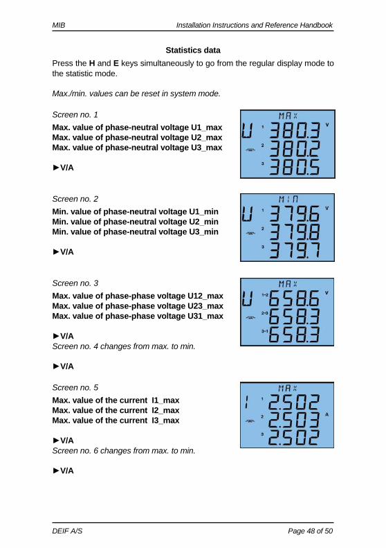
Statistics data Press the H and E keys simultaneously to go from the regular display mode to the statistic mode. Max./min. values can be reset in system mode.
Screen no. 1 Max. value of phase-neutral voltage U1_max Max. value of phase-neutral voltage U2_max Max. value of phase-neutral voltage U3_max V/A
Screen no. 2 Min. value of phase-neutral voltage U1_min Min. value of phase-neutral voltage U2_min Min. value of phase-neutral voltage U3_min V/A
Screen no. 3 Max. value of phase-phase voltage U12_max Max. value of phase-phase voltage U23_max Max. value of phase-phase voltage U31_max V/A Screen no. 4 changes from max. to min. V/A
Screen no. 5 Max. value of the current I1_max Max. value of the current I2_max Max. value of the current I3_max V/A Screen no. 6 changes from max. to min. V/A
MIB Installation Instructions and Reference Handbook
DEIF A/S Page 49 of 50
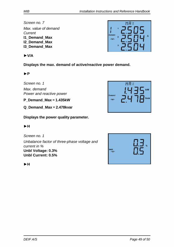
Screen no. 7 Max. value of demand Current I1_Demand_Max I2_Demand_Max I3_Demand_Max V/A Displays the max. demand of active/reactive power demand. P
Screen no. 1 Max. demand Power and reactive power
P_Demand_Max=1.435kW
Q_Demand_Max=2.478kvar
Displays the power quality parameter. H
Screen no. 1 Unbalance factor of three-phase voltage and current in % Unbl Voltage: 0.3% Unbl Current: 0.5% H
MIB Installation Instructions and Reference Handbook
DEIF A/S Page 50 of 50
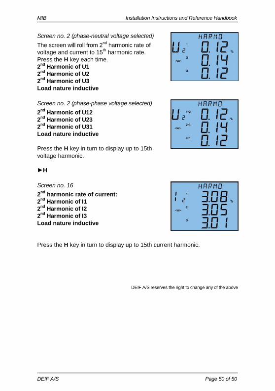
Screen no. 2 (phase-neutral voltage selected) The screen will roll from 2nd harmonic rate of voltage and current to 15th harmonic rate. Press the H key each time. 2nd Harmonic of U1 2nd Harmonic of U2 2nd Harmonic of U3 Load nature inductive
Screen no. 2 (phase-phase voltage selected) 2nd Harmonic of U12 2nd Harmonic of U23 2nd Harmonic of U31 Load nature inductive Press the H key in turn to display up to 15th voltage harmonic. H
Screen no. 16 2nd harmonic rate of current: 2nd Harmonic of I1 2nd Harmonic of I2 2nd Harmonic of I3 Load nature inductive Press the H key in turn to display up to 15th current harmonic.
DEIF A/S reserves the right to change any of the above