Refer to Chapter 9 Interchange Design
26
November 1, 2021 9-1 Chapter 9 Interchange Design An interchange is a system of interconnecting roadways in conjunction with one or more grade separations that provides for the movement of traffic between two or more roadways on different levels when at least one of the roadways is a freeway. The meeting of two non-freeways using some type of bridge is called a grade-separated intersection and is not covered in this chapter. Refer to Selecting Optimum Intersection or Interchange Alternatives (SOIIA), by Joseph E. Hummer, PhD, PE, on the Congestion Management Section website for ways in which these intersections should be treated differently from interchanges. Refer to GB Chapter 10 before beginning the planning or design of any interchange. 9.1 Introduction The type of interchange configuration best suited for a particular site is influenced by the following factors: Number of legs Expected volumes of through and turning movements Type of truck traffic Topography Continuity Design controls Proper signing Control of access Exits along a freeway corridor should have some degree of conformity. Ramps at each interchange should serve all basic directions to minimize potential for wrong-way movements. On a freeway system, interchanges that serve all movements is a basic requirement. Movement through the interchange should be as direct and convenient as practical. Interchanges in urban or partial urban areas should consider accommodation of pedestrians and bicyclists. Interchange configurations generally fall into two categories – system interchanges and service interchanges. System interchanges describe interchanges that connect two or more freeways and provide for continuous free flow movement. Service interchanges are those that connect a freeway to a facility with a lower classification. These interchanges are typically stop, yield, or signal controlled and do not provide free flow movement on the non-freeway. In rural areas, interchange configurations are typically selected based on service demand. Interchanges in rural areas can typically be designed on an individual basis without any appreciable effect from other interchanges within the system. Determine interchange configurations by the relative safety history of different ramp terminal configurations, need for route continuity, uniformity of exit patterns, single exits in advance of the separation structure, elimination of weaving on the main facility, signing potential, and availability of right of way. Selecting an appropriate interchange in an urban environment involves considerable analysis of prevailing conditions so the safest, most efficient, and most practical interchange configuration alternatives can be developed. In urban areas, each interchange may be influenced directly by
Transcript of Refer to Chapter 9 Interchange Design
November 1, 2021 9-1
Chapter 9 Interchange DesignAn interchange is a system of interconnecting roadways in conjunction with one or more grade separations that provides for the movement of traffic between two or more roadways on different levels when at least one of the roadways is a freeway. The meeting of two non-freeways using some type of bridge is called a grade-separated intersection and is not covered in this chapter. Refer to Selecting Optimum Intersection or Interchange Alternatives (SOIIA), by Joseph E. Hummer, PhD, PE, on the Congestion Management Section website for ways in which these intersections should be treated differently from interchanges. Refer to GB Chapter 10 before beginning the planning or design of any interchange.
9.1 IntroductionThe type of interchange configuration best suited for a particular site is influenced by the following factors:
Number of legs
Expected volumes of through and turning movements
Type of truck traffic
Topography
Continuity
Design controls
Proper signing
Control of accessExits along a freeway corridor should have some degree of conformity. Ramps at each interchange should serve all basic directions to minimize potential for wrong-way movements. On a freeway system, interchanges that serve all movements is a basic requirement. Movement through the interchange should be as direct and convenient as practical. Interchanges in urban or partial urban areas should consider accommodation of pedestrians and bicyclists.Interchange configurations generally fall into two categories – system interchanges and service interchanges. System interchanges describe interchanges that connect two or more freeways and provide for continuous free flow movement. Service interchanges are those that connect a freeway to a facility with a lower classification. These interchanges are typically stop, yield, or signal controlled and do not provide free flow movement on the non-freeway. In rural areas, interchange configurations are typically selected based on service demand. Interchanges in rural areas can typically be designed on an individual basis without any appreciable effect from other interchanges within the system. Determine interchange configurations by the relative safety history of different ramp terminal configurations, need for route continuity, uniformity of exit patterns, single exits in advance of the separation structure, elimination of weaving on the main facility, signing potential, and availability of right of way.Selecting an appropriate interchange in an urban environment involves considerable analysis of prevailing conditions so the safest, most efficient, and most practical interchange configuration alternatives can be developed. In urban areas, each interchange may be influenced directly by

Roadway Design Manual Interchange Design
November 1, 2021 9-2
the preceding or following interchange to the extent that additional traffic lanes may be needed to satisfy capacity, weaving, and lane balance.Consider the geometric layout and balance the impacts for each interchange design. Consider the following factors when analyzing whether the interchange is appropriate for the location:
Relative safety of ramp terminal configurations
Capacity
Route continuity
Uniformity of exit patterns
Weaving
Potential for appropriate signing
Cost
Availability of right of way
Construction phasing
Compatibility with the environment
Quality of the pedestrian and bicyclist crossing Work closely with the NCDOT Congestion Management Section to determine the best form to achieve the operational goals and minimize impacts.Refer to GB Chapter 10 Section 10.9.5 for more information on determining interchange configurations.
9.2 Interchange Configurations9.2.1 Three-Leg DesignsA three-leg interchange design is difficult to expand or modify and should typically only be used when a fourth leg is not considered in a future expansion. Refer to GB Chapter 10 Section 10.9.2 Figures 10-9 through 10-12 for illustrations of three-leg interchange design patterns. Refer to GB Chapter 10 Section 10.9.2 and SOIIA Three-Legged section for a detailed discussion of three-leg interchanges including advantages, disadvantages, and niche uses.
9.2.2 Four-Leg DesignsInterchanges with four intersection legs generally fall under the following general configurations.
9.2.2.1 Ramps in One QuadrantInterchanges with ramps in only one quadrant have typical application for an intersection of roadways with low traffic volumes where a grade separation is provided due to topography, as part of an initial phase of a staged construction program, where right of way is unavailable in several quadrants, or on a toll facility to limit the number of toll collection facilities. Appropriate locations for this type of interchange are therefore limited.

Roadway Design Manual Interchange Design
November 1, 2021 9-3
Refer to GB Chapter 10 Section 10.9.3.1 Figure 10-15 for illustrations of four-leg interchanges with ramps in one quadrant. Refer to GB Chapter 10 Section 10.9.3.1 and SOIIA Table 8 for a detailed discussion and a listing of advantages, disadvantages, and niche uses.
9.2.2.2 Diamond InterchangesDiamond interchanges are the simplest and most common interchange configuration. Some advantages of diamond interchanges are they allow traffic to enter and exit the major road at relatively high speeds, require very little out of direction travel, need relatively narrow widths of right of way, and treat pedestrians and bicyclists relatively well. Disadvantages include limited capacity and poor signal progression capability. Diamond interchanges with smaller distances between ramp terminals (i.e., tight diamonds) operate quite differently from diamond interchanges with longer distances between ramp terminals (i.e., standard or spread diamonds). Consult interchange operation experts to be sure the type of design matches the desired operation. Refer to SOIIA for a list of advantages, disadvantages, and niche uses of the different types of diamond interchanges.Refer to GB Chapter 10 Section 10.9.3.2 Figures 10-17 through 10-19 for illustrations of diamond interchanges. Refer to GB Chapter 10 Section 10.9.3.2 and SOIIA Table 7 for detailed information including additional advantages, disadvantages, and niche uses.
9.2.2.3 Roundabout InterchangesRoundabout interchanges typically refer to a diamond interchange with roundabouts at the crossroad ramp terminals. The roundabouts can be single lane or multilane. Refer to GB Chapter 9 Section 9.10 and TRB NCHRP Research Report 672: Roundabouts: An Informational Guide for roundabout design and operations.Refer to GB Chapter 10 Section 10.9.3.3 Figure 10-22 and SOIIA Table 8 for more information including advantages, disadvantages, and niche uses.
9.2.2.4 Single Point Diamond InterchangesThe primary features of a single point diamond interchange (SPDI), also commonly referred to as single point urban interchanges (SPUI), are that all four left-turning movements are controlled by a single traffic signal and opposing left turns operate to the left of each other. Typical characteristics of an SPDI are narrow right of way, high construction costs, and greater capacity than typical diamond interchanges. Consideration for potentially complicated structure geometry should be given as early as possible if this type of interchange is being considered. Refer to GB Chapter 10 Section 10.9.3.4 Figures 10-23 through 10-26 for illustrations of SPDI. Refer to GB Chapter 10 Section 10.9.3.4 and SOIIA Table 7 for more information including advantages, disadvantages, and niche uses.
9.2.2.5 Diverging Diamond InterchangesThe diverging diamond interchange (DDI) uses directional crossover intersections to shift traffic on the cross street to the left-hand side between the ramp terminals within the interchange. This eliminates the need for exclusive left-turn signal phases. DDI design allows for the ramp
Roadway Design Manual Interchange Design
November 1, 2021 9-4
terminal intersections to operate with simple, two-phase signal operations that provide flexibility to accommodate varying traffic patterns. It also has fewer conflict points when compared to a conventional diamond interchange. Traffic control and bridge staging can be complex. Consider superstructure depth and vertical clearances between roadways and bridges, especially during a retrofit or structure widening. It is good practice to utilize a normal crown typical section through the DDI. Use engineering judgement and document design decisions.Refer to GB Chapter 10 Section 10.9.3.5 for detailed information on DDIs and Figure 10-27 for illustrations of DDI layouts. Refer to SOIIA for a list of advantages, disadvantages, and niche uses. Refer to TRB NCHRP Research Report 959: Diverging Diamond Interchange Informational Guide, Second Edition for additional information.
9.2.2.6 Cloverleaf/Partial Cloverleaf InterchangesCloverleafs are interchanges that employ loop ramps to accommodate left-turning movements. Interchanges with loops in all four quadrants are referred to as full cloverleafs; all others are referred to as partial cloverleafs or “parclos”. These interchanges are less common in urban areas than in suburban or rural areas with available space.Refer to GB Chapter 10 Section 10.9.3.6 for examples and detailed discussion of cloverleaf interchanges and Figures 10-28 through 10-32 for illustrations of cloverleaf and parclo interchanges. Refer to Section 9.3.5 below for information on weaving. Refer to SOIIA for information on the types of parclo commonly used in North Carolina including advantages, disadvantages, and niche uses.
9.2.2.7 Directional InterchangesDirect or semidirect interchange connections are used for important turning movements to reduce travel distance, increase speed and capacity, eliminate weaving, and avoid the need for out-of-direction travel in driving on a loop. A direct connection is defined as a ramp that does not deviate greatly from the intended direction of travel. Direct connections are generally designed with higher design speeds than other connections. Refer to GB Chapter 10 Section 10.9.3.7 and Figures 10-33 through 10-39 for more information and examples of directional interchanges.
9.2.2.8 Other Interchange ConfigurationsRefer to GB Chapter 10 Section 10.9.4 and SOIIA for other interchange configurations including:
Offset interchanges
Combination interchanges
Three-level interchanges
Median U-turn interchanges
Folded interchanges
Signalized FRE interchanges

Roadway Design Manual Interchange Design
November 1, 2021 9-5
Synchronized interchanges
Various System (freeway to freeway) Interchange Designs
9.3 General Design Considerations9.3.1 Alignment, Profile, and Cross SectionThe design speed, alignment, profile, and cross section in the intersection area, should be consistent with those on the approaching highways. This is not always easily attainable. Maintain a relatively flat alignment and profile of the through highways at the interchange to provide high visibility. Refer to GB Chapter 10 Section 10.9.5.2.1 for detailed information.
9.3.2 Sight DistanceSight distance on the highways through a grade separation should be at least as long as needed for stopping and preferably longer. Where exits are involved, decision sight distance is preferred, although not always practical. Refer to GB Chapter 10 Section 10.9.5.2.2 for more information.
9.3.3 Interchange SpacingSince both interchange and ramp spacing influence freeway operations, a general rule of thumb for minimum interchange spacing is 1-mile in urban areas and 2 miles in rural areas. In urban areas, spacings of less than 1-mile may be developed by grade-separated ramps or by adding collector-distributor roads. Refer to GB Chapter 10 Section 10.9.5.3 Figure 10-47 for an illustration on how interchange spacing is measured. Refer to GB Chapter 10 Section 10.9.6.3 and Section 9.4 below for more information on ramp spacing.
9.3.4 Auxiliary LanesAn auxiliary lane is defined as the portion of the roadway adjoining the through lanes for speed change, turning, storage for turning, weaving, truck climbing, and other purposes that supplement through-traffic movement. The width of the auxiliary lane should equal the width of the through lane. Refer to GB Chapter 10 Section 10.9.5.10 for a detailed discussion of auxiliary lanes, as well as examples, and illustrations.
9.3.5 Weaving SectionsWeaving sections are highway segments where the pattern of traffic that enters and leaves at contiguous points of access produces vehicle paths that cross each other. These weaving sections may occur within an interchange, between entrance ramps in one interchange and exit ramps in a downstream interchange, or on segments of overlapping roadways. Interchange designs that eliminate or minimize weaving are desirable due to the conflict points that are created. Discuss weaving sections with Congestion Management.

Roadway Design Manual Interchange Design
November 1, 2021 9-6
Refer to GB Chapter 10 Section 10.9.5.12 for more information on weaving sections and GB Chapter 2 Section 2.4.6.1 for information on procedures for determining weaving lengths and widths.
9.3.6 Collector-Distributor RoadsThis section is in reference to collector-distributor roads within an interchange, such as full cloverleaf interchanges. Collector-distributor roads may be one or two lanes in width depending on capacity needs. On the collector-distributor roadway designers should try to maintain a design speed of not less than 10 mph below the design speed of the main roadway. Design outer separation between the mainline and the collector-distributor road as wide as practical, allowing for shoulder widths equal to that on the mainline as well as a suitable barrier to prevent crossing over. Refer to GB Chapter 10 Section 10.9.5.13 for more information and advantages of collector-distributor roads within interchanges.Refer to GB Chapter 8 Section 8.4.7.3 for collector-distributor roads between two interchanges and continuous collector-distributors.
9.3.7 Control of Access at InterchangesProvide control of access along all ramps and on -Y- lines at interchanges for a minimum of 1,000 feet beyond the ramp intersections. If for some reason this is not practical, provide full control of access for 350 feet and use a raised island to eliminate left turns for the remaining 650 feet.
9.3.8 Pedestrians and Bicyclists at InterchangesBicyclists and pedestrians are expected at all intersections and interchange approaches unless not permitted legal access. Design interchange ramps to cross bicycle and pedestrian networks where driver visibility of the crossing is clear (preferably at a 90-degree angle). Refer to AASHTO Guide for the Development of Bicycle Facilities, AASHTO Guide for the Planning, Design, and Operation of Pedestrian Facilities, SOIIA, and TRB NCHRP Research Report 948: Guide for Pedestrian and Bicycle Safety at Alternative and Other Intersections and Interchanges for more information.
9.4 RampsOne of the primary components of interchanges is ramps. Ramps are roadways that connect a highway facility to one or more highway facilities at an interchange. There are a variety of ramp types and they can be broadly classified as diagonal, loop, directional, semidirect, outer connection and one quadrant. The following information provides details on ramp design and design decisions to consider.Spiral curves should be used for all ramp and loop alignments on high-speed facilities. Refer to GB Chapter 10 Section 10.9.6 for more information on ramps.
9.4.1 General Ramp Design ConsiderationsThere are different types of ramps and depending on the location and types of facilities, the ramps will have different design features.

Roadway Design Manual Interchange Design
November 1, 2021 9-7
9.4.1.1 Ramp Design SpeedsRamp design speeds should approximate the low volume running speed on the intersecting highways. This design speed is not always practicable and lower design speeds may be necessary. NCDOT preference is to design for the upper range unless there are constraints that prohibit using this range.
Table 9-1 Guide Values for Ramp Design Speed as Related to Highway Design Speed
Note: Ramp design speeds above 30 mph are seldom applicable to loops. For highway design speeds of more than 50 mph, the loop design speed should not be less than 25 mph (150-foot radius).
Source: GB Chapter 10 Section 10.9.6.2.2 Table 10-1
A simple rule of thumb commonly used is a 60 mph/40 mph design speed split for exit ramps on a service interchange. This rule is based on a single lane exit ramp from a 70-mph posted facility and applies a 60-mph design speed for the first half of the ramp and a 40-mph design speed for the second half of the ramp. This rule provides general guidance that allows the designer to reduce the design speed as the exiting vehicle decelerates as it approaches the intersection. Refer to GB Chapter 10 Section 10.9.6.2 for more information on ramp design speed. Provide appropriate deceleration and acceleration lanes for all ramps. Refer to GB Chapter 10 Section 10.9.6.5.2 Tables 10-4 and 10-5 and NCDOT Roadway Standard Drawings Std. No. 225.03 for information on ramp acceleration and deceleration lanes
9.4.1.2 Ramps for Right TurnsGB Chapter 10 Table 10-1 provides a guideline for ramp design speeds in relation to highway design speed. These values apply to the sharpest exit or entrance radius, not the radii at the ramp terminals. When applying the portion of a ramp to which design speed is applicable, the upper range of design speeds is usually achievable for ramps for right turns. Refer to GB Chapter 10 Section 10.9.6.2.3 and Table 10-1 for more information on ramps for right turns.
9.4.1.3 Loop RampsRamp design speeds above 30 mph are seldom applicable to loops. For highway design speeds of more than 50 mph, the loop design speed should not be less than 20 mph. While the GB allows for a 20-mph design speed, NCDOT uses 25 mph with 150-foot radius as the minimum design for loops.Place a 2′-6″ curb and gutter on the inside or right side of traffic on all loops. Design pavement widths to meet the widths for Case II (provision for passing a stalled vehicle) as shown in GB Chapter 3 Section 3.3.11.2 Table 3-27.
Highway design speed (mph) 30 35 40 45 50 55 60 65 70 75 80
Upper range (85%) 25 30 35 40 45 50 50 55 60 65 70Middle range (70%) 20 25 30 30 35 40 45 45 50 55 60Lower range (50%) 15 20 20 25 25 30 30 30 35 40 45Corresponding minimum radius (ft)
Ramp design speed (mph)
See GB Chapter 3 Section 3.3.3.3 Table 3-7

Roadway Design Manual Interchange Design
November 1, 2021 9-8
Loop ShouldersRefer to RDM Part I Chapter 4 Section 4.4.2 for width of usable shoulder on outside of loops.
Loop Alignments: Freeways – 150-foot to 250-foot radii unless conditions warrant otherwise. On interstates,
design loops for a 30-mph design speed where feasible. (230-foot radii minimum for 30-mph design speed).
Expressways – A 150-foot radius is acceptable on highways with a 50-mph or less design speed.
Two-Lane Loops – 180-foot to 200-foot minimum radii along the inside edge of travel. Provide appropriate deceleration and acceleration lanes for all loops. Refer to GB Chapter 10 Section 10.9.6.5.2 Tables 10-4 and 10-5 and NCDOT Roadway Standard Drawings Std. No. 225.03 for information on ramp acceleration and deceleration lanes.
9.4.1.4 At-grade TerminalsNote that ramp design speed can be lowered where the ramp approaches and ties into an at-grade, stop condition intersection.Refer to GB Chapter 10 Section 10.9.6.2.9 and Section 9.4.3 below for additional at-grade terminal information.
9.4.1.5 CurvatureRefer to GB Chapter 3 Section 3.3 for guidelines for the design of ramp curves at interchanges.
Table 9-2 Desirable Curvature for Ramps in the Vicinity of the Gore Area
Refer to GB Chapter 10 Section 10.9.6.2.10 and NCDOT Roadway Standard Drawings Std. No. 225.03 for additional ramp curvature information.
9.4.1.6 Sight DistanceVariables to consider in the evaluation of sight distance design options include grades, horizontal alignment, guardrail, skew, earthwork cost, right of way cost, handrail offset and bridge cost. Another design element of importance is stopping sight distance from ramps that exit the mainline from beneath a bridge. The reduced offset from edge of pavement to piers or end bent fill slopes may restrict the stopping sight distance in these cases. Design the proper combination of pier location and ramp alignment to provide a minimum stopping sight distance of 350 feet.Give the same attention to a ramp that exits the mainline immediately after crossing a bridge. Design the proper combination of bridge rail offset and ramp alignment so the bridge railing
Ramp Type Desirable CurvatureRural Exit 3 to 5 degreesRurtal Entrance 3 to 5 degreesUrban Exit 4 to 6 degreesUrban Entrance 3 to 6 degrees

Roadway Design Manual Interchange Design
November 1, 2021 9-9
does not restrict the required stopping sight distance for the ramp. Check these sight lines graphically.With reduced bridge railing offsets specified in the RDM Part I Chapter 5, horizontal sight distance has become a more critical element of interchange design. Because a narrow bridge can restrict the horizontal sight line, consider a combination of ramp terminal location, the -Y- line grade, and the bridge rail offset to attain the required sight distance across the bridge. Study each interchange design individually to achieve the most cost-effective combination of bridge width, ramp terminal location, and -Y- line grade. Use a 6-foot minimum bridge rail offset on interchange bridges.Four basic options are available to the roadway designer for providing the required horizontal sight distances:
1. Design the -Y- line grade to enable the driver to see over the bridge rail and guardrail if present. Table 9-3 provides K values for -Y- line grades that will enable the ramp vehicle driver to see over the bridge rail.
2. Increase the bridge rail offset and allow the horizontal sight line to fall inside the handrail. Table 9-3 provides K values for -Y- line grades that will allow a clear sight line inside the bridge handrail.)
3. Use the minimum bridge rail offset required by RDM Part I Chapter 5 and locate the ramp terminal a sufficient distance from the end of the bridge to provide the required sight distance. Table 9-4 shows the distance required from the end of the bridge to ramp terminal to provide the required horizontal sight distance with various bridge rail offset distances. Conversely, Table 9-4 can show the available horizontal sight distance with set ramp terminals and handrail offset distances. Table 9-4 may also be used to derive combinations of handrail offsets and ramp terminal locations that may be necessary in an economic analysis of the interchange layout.)
4. Consider designing grades with the mainline carried over the -Y- line. This design may be cost-effective with a narrow median on the mainline and a multilane -Y- line. Earthwork costs are usually the critical cost elements in this option.
Refer to GB, Chapter 10, Section 10.9.5.2.2 for sight distance information.
9.4.1.7 Grade and Profile DesignUse the following list of maximum grades to be used in ramp design:
1. Do not exceed 5 percent for a 50-mph design speed, or 6 percent for a 40-mph design speed, do not exceed 5 percent in areas subject to snow and ice.
2. Limit increasing grades to 4 percent where the ramp is to be used by a high volume of heavy trucks.
3. In exceptional cases, as with loops and urban area ramps, grades may be as steep as 10 percent. However, grades this steep should usually be limited to minor ramps with low volumes. A steep grade on a ramp is not objectionable if the gradient aids acceleration on entrance ramps or deceleration on exit ramps.
4. Use flatter grades for entrance ramps with high design speeds or those joining high-speed highways generally than for ramps with low design speeds or minor, light-volume ramps.
5. Limit grades on ramps with sharp horizontal curvature on downgrades as the high rate of superelevation in conjunction with a steep downgrade makes steering difficult.

Roadway Design Manual Interchange Design
November 1, 2021 9-10
6. If a ramp gradient does not aid the acceleration on entrance ramps or deceleration on exit ramps, take care to provide the appropriate ramp length to provide adequate distance for the driver to make the required speed change.
7. Avoid use of sag vertical curves in cut sections when possible.Refer to GB Chapter 10 Section 10.9.6.2.12 Table 10-2 for more information on maximum ramp grades. Use the following procedure for establishing ramp grades with control points:
1. GIVEN:a. Mainline alignment, stationing, grade, pavement width, and superelevation.b. Ramp alignment, stationing, pavement width, superelevation, and nose
station.2. FIND: Ramp grade in the area adjacent to the mainline at the exit or entrance point.3. PROCEDURE:
a. Establish a series of control point elevations along the ramp survey line (or grade point) for the ramp grade to pass through in order to provide a smooth, drivable pavement surface at the exit or entrance gore.
i. Using a plan sheet with completed horizontal alignment, layout a series of cross section lines at approximately 25′ to 50′ intervals at pertinent points along the ramp and mainline alignment. A section should be placed at the beginning station and nose station on the ramp. Sections between these points can be placed at random locations in order to adequately cover the pavement. A section should also be placed 200′ to 300′ beyond the nose station to check the proposed ditch slopes between the ramp and mainline. Refer to Figure 9-1 for an example layout.
ii. Using the mainline grade, pavement width, and superelevation, calculate the mainline edge of pavement elevations adjacent to the ramp at those mainline stations selected with the cross section layout.
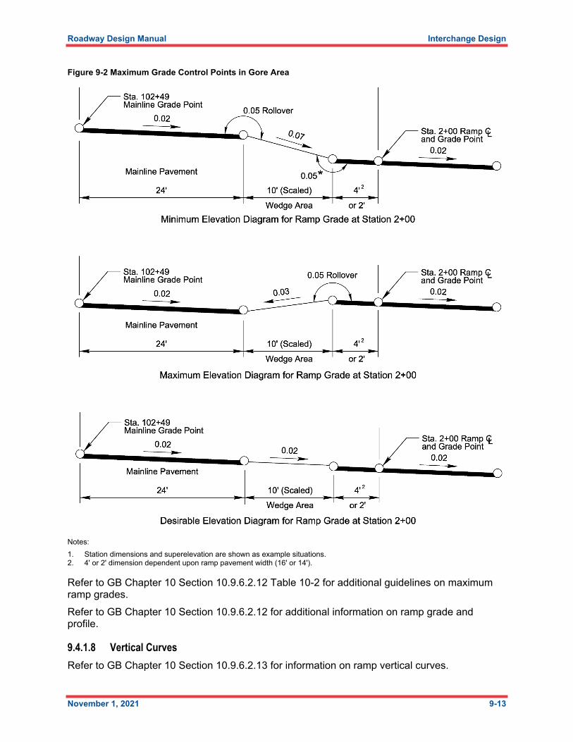
iii. Establish a maximum, minimum, and desirable elevation at each ramp station selected with the cross section layout. The maximum and minimum range is obtained by applying various superelevation rates on the pavement in the wedge area between the mainline and ramp edges of pavement. The various rates of superelevation in the wedge area are selected by applying a maximum 0.05 roll-over at the mainline edge of pavement and then at the ramp edge of pavement adjacent to the wedge area. Refer to Figure 9-2 for an example. It should be noted that the 0.05 roll-over limit is to be used with discretion in each case so that the resultant superelevation does not create an impractical or awkward section in the wedge area. After selecting a range of superelevation and scaling the width of the wedge area, calculate the maximum and minimum elevation adjustments, due to the wedge superelevation, at each cross section. An additional superelevation adjustment calculation is made for the area from the ramp edge of pavement to the ramp centerline (4′ or 2′ width for a single lane ramp). Also, a desirable or ideal elevation adju

Roadway Design Manual Interchange Design
November 1, 2021 9-11
stment is of value in computing the ramp grade. This is calculated by assigning the ideal or most comfortable superelevation in the wedge area. This desirable elevation adjustment will obviously fall within the maximum and minimum range as described above.At this point, the maximum, minimum, and desirable elevation adjustments are applied to the mainline edge of pavement elevations at each set of stations to provide a series of elevations on the ramp centerline thru which the proposed ramp grade must pass. It is helpful to prepare a chart for listing the various stations and their respective superelevation and elevation adjustments in calculating the maximum, minimum and desirable elevations.

Roadway Design Manual Interchange Design
November 1, 2021 9-12
Figure 9-1 Ramp Gore Grade Control Points
Note: * Indicates variable dimensions or station. Given dimensions shown are for example computations.
Roadway Design Manual Interchange Design
November 1, 2021 9-13
Figure 9-2 Maximum Grade Control Points in Gore Area
Notes: 1. Station dimensions and superelevation are shown as example situations.2. 4' or 2' dimension dependent upon ramp pavement width (16' or 14').
Refer to GB Chapter 10 Section 10.9.6.2.12 Table 10-2 for additional guidelines on maximum ramp grades.Refer to GB Chapter 10 Section 10.9.6.2.12 for additional information on ramp grade and profile.
9.4.1.8 Vertical CurvesRefer to GB Chapter 10 Section 10.9.6.2.13 for information on ramp vertical curves.

Roadway Design Manual Interchange Design
November 1, 2021 9-14
9.4.1.9 Superelevation and Cross SlopeFollow guidelines in GB Chapter 10 Section 10.9.6.2.14 for cross slope design on ramps.
9.4.1.10 GoresGores are the areas between the through roadway and the exit or entrance ramps. There are three types of gore areas: taper, parallel, and major fork. Keep gore areas free of obstacles and traversable to protect errant vehicles.Refer to NCDOT Roadway Standard Drawings, Std. No. 225.03 for information on gore layout.Refer to GB Chapter 10 Section 10.9.6.2.15 for additional gore information and Figure 10-64 for examples of gore types.
9.4.2 Ramp Traveled Way WidthsRefer to RDM Part I Chapters 4.2 and 4.3 and GB Chapter 10 Section 10.9.6.3 for information on ramp traveled way widths.
9.4.2.1 Width and Cross SectionPavement width is generally 14 feet. Consider using a width of 16 feet where traffic volumes or truck percentages are high. Use a width of 16 feet on the interstate system.Refer to GB Chapter 3 Section 3.3 Table 3-27 for design widths of ramp traveled ways for various conditions. Refer to GB Chapter 10 Section 10.9.6.3.1 for additional information on ramp width and cross section.
9.4.2.2 Shoulder Widths and Lateral OffsetRefer to RDM Part I Chapter 4.4 for usable shoulder width. Paved shoulders are required on both sides of the ramp.Refer to GB Chapter 10 Section 10.9.6.3.2 for more information on shoulder widths and lateral offset.
9.4.2.3 Shoulders and CurbsRefer to GB Chapter 10 Section 10.9.6.3.3; RDM Part I Chapter 4; and NCDOT Paved Shoulder Policy for information on shoulders and curbs.
9.4.3 Ramp TerminalsThe ramp terminal of an interchange is that part of the ramp next to the through traveled way. Ramp terminals may be designed as an at-grade type, where traffic is controlled with a stop condition, roundabout, or signal at the intersecting roadway; or designed as a free-flow type where traffic merges with the intersecting roadway in a continuous flow.
9.4.3.1 Diamond Interchange Terminal Location and Sight Distance At crossroads, locate ramp terminals far enough away from the grade separation structure to provide adequate sight distance except in configurations like the tight diamond where this is not possible. Tables 9-3 and 9-4 provide additional information on sight distance on -Y- lines at diamond interchanges.

Roadway Design Manual Interchange Design
November 1, 2021 9-15
Table 9-3 Vertical Sight Distance Control for Crest Curves at Interchanges, Single Unit Vehicle Criteria
Notes:
1. * Denotes minimum “K” to be used for each design speed.2. Sight distance “d” is established by GB criteria for the intersection sight distance of Case B1 (Left Turn from the Minor Road for
Intersections with Stop Control on the Minor Road). Refer to GB Chapter 9 Section 9.5.3 for more information.3. Minimum “K” for stopping sight distance according to GB. Refer to GB Chapter 3 Section 3.4.6 Table 3-35.4. “K” derived from GB Chapter 3 Section 3.4.6 Formula 3-42 (applying K = L / A) using h1 = 7.6′ as the eye height of a truck driver
and h2 = 4.35′ as the object height of a vehicle as suggested in GB Chapter 9 Section 9.5.2.5. “K” derived from GB Chapter 3 Section 3.4.6 Formula 3-42 (applying K = L / A) but assuming a rail height of 2.67′ and
subtracting said rail height from the eye and object heights (h1 = 4.93′, h2 = 1.68′).
Figure 9-3 Vertical Sight Distance Control for Crest Curves at Interchanges, Single Unit Vehicle Criteria
Note: Vertical sight distance should be provided in combination with horizontal sight controls. The design data listed in Table 9-3 is based on utilizing the SU vehicle as the ramp vehicle. With a passenger car as the ramp vehicle, the sight distance provided with the design data listed in Table 9-3 allows for approach speeds greater than the crossroad design. With a combination truck, the available sight distance allows for approach speeds of about 80 percent of the crossroad design speed, which is approximately the average running speed of the crossroad traffic.
Crossroad Design Speed
Sight Distance "d" Required for SU
Ramp Vehicle, Left Turn Maneuver
(See Note 2)
"K" Required for Stopping Sight Distance along
Crossroad
(See Note 3)
"K" Required to Provide Sight
Distance "d" for SU Ramp Vehicle Left
Turn Maneuver
(See Note 4)
"K" Required to Provide Sight Distance "d" for SU
Ramp Vehicle Sighting over Bridge Rail
(See Note 5)
70 mph 980' 247 * 205 389
60 mph 840' 151 * 151 286
50 mph 700' 84 105 199
40 mph 560' 44 67 127
Notes:
2. Sight distance "d" is established by GB criteria for the intersection sight distance of Case B1 (Left Turn from the Minor Road for Intersections with Stop Control on the Minor Road). Refer to GB Chapter 9 Section 9.5.3 for more information.
3. Minimum "K" for stopping sight distance according to the GB. Refer to GB Chapter 3 Section 3.4.6 Table 3-35.
4. K derived from GB Chapter 3 Section 3.4.6 Formula 3-42 (applying K = L/A) using h1 = 7.6' as the eye height of a truck driver and h2 = 4.35' as object height of a vehicle as suggested in GB Chapter 9 Section 9.5.2.5. K derived from GB Chapter 3 Section 3.4.6 Formula 3-42 (applying K = L/A) but assuming a rail height of 2.67' and subtracting said rail height from the eye and object heights (h1 = 4.93', h2 = 1.68').
1. * Denotes minimum "K" to be used for each design speed.
**
K = d2
100 ( 2h1 + 2h2)2

Roadway Design Manual Interchange Design
November 1, 2021 9-16
Figure 9-4 Design Requirements for Crossroad Sight Distance at Interchanges, Single Unit Vehicle Criteria
Notes: 1. Definitions
“a” - Offset from the edge of the travel lane to the inside edge of the bridge rail.“c” - Distance required from the end of the bridge to the decision point on the ramp terminal.“d” - Sight distance measured along the major road of the intersection sight triangle.“k” - The offset from the major road edge of the travel lane to the decision point of the departure sight triangle on the major
road.“m” - The offset from the major road edge of the travel lane to the decision point of the departure sight triangle on the minor
road (ramp terminal).2. Sight distance “d” is established by GB criteria for the intersection sight distance of Case B1 (Left Turn from the Minor Road for
Intersections with Stop Control on the Minor Road). Refer to GB Chapter 9 Section 9.5.3 for more information.3. Decision point offsets “k” and “m” are set based on guidance in GB. Refer to GB Chapter 9 Section 9.5.
Table 9-4 “c” Distance Required from End of Bridge to Ramp Terminal
Note: Distances “c” in Table 9-4 are determined based on the formula shown in Figure 9-4 above using “m” = 18′ and “k” = 6′. Sight distance “d” is determined using GB Chapter 9 Section 9.5.3 Formula 9-1, the values in GB Table 9-6 (tg = 9.5 s), and assuming an approach grade flatter than 3 percent. Refer to GB Chapter 9 Section 9.5. Use formula shown in Figure 9-4 to calculate “c” for all other conditions.
2' 4' 6' 8' 10'15 140' 125' 105' 90' 70'20 190' 165' 140' 120' 95'25 235' 205' 175' 150' 120'30 280' 245' 210' 175' 140'35 330' 290' 245' 205' 165'40 375' 330' 280' 235' 190'45 420' 370' 315' 265' 210'50 470' 410' 350' 295' 235'55 515' 450' 385' 325' 260'60 560' 490' 420' 350' 280'65 610' 535' 455' 380' 305'70 655' 575' 490' 410' 330'75 700' 615' 525' 440' 350'80 750' 655' 560' 470' 375'
Design Speed (mph)
Rail Offset (ft) "a"
Note: Distances “c” in Table 9-4 are determined based on the formula shown in Figure 9-4 above using “m” = 18′ and “k” = 6′. Sight distance “d” is determined using GB Chapter 9 Section 9.5.3 Formula 9-1, the values in GB Table 9-6 (tg = 9.5 s), and assuming an approach grade flatter than 3 percent. Refer to GB Chapter 9 Section 9.5. Use formula shown in Figure 9-4 to calculate “c” for all other conditions.

Roadway Design Manual Interchange Design
November 1, 2021 9-17
Refer to GB Chapter 3 Section 3.2 and Chapter 7 Section 7.2.2.4 for sight distance criteria. Design all ramp terminals to handle the WB-67 design vehicle. Refer to RDM Part I Chapter 8 Section 8.5 for additional information.Pay special attention at ramp terminals to discourage wrong-way entry. At locations with unusual ramp termini configurations, consider a raised median on the -Y- line.On partial cloverleaf and diamond type interchanges, provide a recovery area for left turning vehicles (turning lane), as shown in Figure 9-5. Figures 9-5 and 9-6 show a typical transition for pavement widening at interchange ramp terminals.Figure 9-8 and Figure 9-9 show designs for loop ramp terminal radii that will provide safe ingress movements for speeds between 20 and 25 mph. In designing ramps, use these designs as an absolute minimum. Flatter radii may be provided if the designer feels the conditions warrant their use.Figure 9-9 identifies acceptable ramp terminal skews.

Roadway Design Manual Interchange Design
November 1, 2021 9-18
Figure 9-5 -Y- Line Transition at Ramp Terminal for Three-Lane -Y- Line Section
Notes: 1. Begin EOP taper at location of the last radius.2. Location of end of island to be determined by prohibiting a left turn move.3. Right turn warrants and length should be according to RDM Part I Chapter 8.4. Five-lane -Y- line section should be set up the same as the three-lane section with additional lanes on the outside.5. Taper length “L” should be as follows:
a. Tapers for design speeds of 45 mph and above should use L = S*Wb. Tapers for design speeds of less than 45 mph should use L = W*S /60
L = Length of taperW = Offset in feetS = Design speed

Roadway Design Manual Interchange Design
November 1, 2021 9-19
Figure 9-6 Ramp Terminal Design
Notes: 1. For a three-lane -Y- line section, a painted island is acceptable, or it can be eliminated completely. On a five-lane -Y- line section, a concrete island should be utilized to separate
opposing traffic on the bridge.2. Turning movements should be designed for a WB-67.

Roadway Design Manual Interchange Design
November 1, 2021 9-20
Figure 9-7 Plan for Loop Ramp Terminal Combination

Roadway Design Manual Interchange Design
November 1, 2021 9-21
Figure 9-8 Section View for Loop Ramp Terminal Combination
Note: In typical scenario the island is constructed at 0.0% cross-slope.
Note: In acceptable scenario the island can be superelevated to match the adjacent roadway cross-slopes.

Roadway Design Manual Interchange Design
November 1, 2021 9-22
Figure 9-9 Acceptable Ramp Terminal Skews
Note: 90° is the preferred ramp skew. Anything within the range of 75° and 105° is considered acceptable.
Refer to GB Chapter 10 Section 10.9.6.4 for more information on terminal location and sight distance.

Roadway Design Manual Interchange Design
November 1, 2021 9-23
9.4.3.2 Distance Between Successive Ramp Terminals on FreewayThe distance between successive ramp terminals needs to be long enough to provide adequate weaving distance and sign spacing for motorists. Table 9-5 presents the recommended minimum distances between successive ramp terminals.
Table 9-5 Recommended Minimum Ramp Terminal Spacing
(1) Arrangement for successive ramp terminalsa. FWY - Freewayb. FDR – Freeway Distributorc. CDR – Collector Distributord. EN – Entrancee. EX – Exit
(2) The recommendations presented in Table 9-5 are based on operational experience and the need for flexibility and adequate signing. They should be checked in accordance with the procedure outlined in the TRB Highway Capacity Manual Sixth Edition (HCM) and the larger of the values is suggested for use. Also, the procedure for measuring the length of the weaving section is given in the HCM. The distances labeled “L” in Table 9-5 are measured between the painted noses; refer to GB Chapter 10 Section 10.9.6.2 Figure 10-63. A minimum distance of 300 feet is recommended between the end of the taper for the first entrance ramp and the painted nose for the succeeding entrance ramp.
Source: GB Chapter 10 Section 10.9.6.4.6 Figure 10-70.
Refer to GB Chapter 10 Section 10.9.6.4.6 for more information on distance between successive ramp terminals.
9.4.4 Single Lane Free Flow Terminals, EntrancesA single lane entrance ramp can be a taper-type or parallel type. Typically, use parallel type entrance ramps on new facilities. When adding or reconstructing an interchange on an existing facility, maintain the exit and entrance type if a definite pattern has been established on the freeway segment. Provide sufficient length to enable a driver to make the necessary change between the speed of operation on the highway and the speed on the turning roadway in a safe and comfortable manner. Refer to GB Chapter 10 Section 10.9 Table 10-4 for minimum acceleration lengths for ramp entrances.The following sections provide greater detail of each entrance type.
Roadway Design Manual Interchange Design
November 1, 2021 9-24
9.4.4.1 Taper-Type EntrancesWhen designed properly, a taper-type entrance ramp (also referred to as an angular entrance or exit) can function smoothly. Taper-type entrance ramps are not typically used in North Carolina.NCDOT Roadway Standard Drawings, Std. No. 225.03 provides details on taper-type entrances.Refer to GB Chapter 10 Section 10.9.6.5.1 for more information on taper-type entrances.
9.4.4.2 Parallel-Type EntrancesUse parallel type entrance lanes in locations where existing interchanges facilities are being upgraded and where right of way is at a premium. The parallel entrance provides additional ramp length (full lane) parallel to the mainline facility allowing the driver adequate time to accelerate and merge.Parallel entrance ramps are preferred in North Carolina. NCDOT Roadway Standard Drawings, Std. No. 225.03 provides details on parallel-type entrances.Refer to GB Chapter 10 Section 10.9.6.5.2 for more information on parallel-type entrances.
9.4.5 Single Lane Free Flow Terminals, ExitsTypically, use taper-type (angular) exit ramps for single lane exits on new facilities. The angular exit separates the exiting vehicle from the mainline traffic. Angular exits are the preferred exit ramp treatment as this provides the fastest separation of through traffic and traffic exiting the through way. When adding or reconstructing an interchange on an existing facility, maintain the exit and entrance type if a definite pattern has been established on the freeway segment. Provide sufficient length to enable a driver to make the necessary change between the speed of operation on the highway and the speed on the turning roadway in a safe and comfortable manner.Refer to GB Chapter 10 Section 10.9.6.5.2 Table 10-5 for minimum deceleration lengths for ramp exit.
9.4.5.1 Taper-Type ExitsTaper-type exits are ramp terminals that exit the throughway at an angle. The taper-type exits at a high level of service and provides a definitive and direct exit location. This direct exit path is preferred by most drivers.The typical angle of departure for angular type exit ramps is between 2 degrees,18 minutes and 4 degrees, 7 minutes.NCDOT Roadway Standard Drawings, Std. No. 225.03 provides details on taper-type exits.Refer to GB Chapter 10 Section 10.9.6.6.1 for more information on taper-type exits.
9.4.5.2 Parallel-Type ExitsA parallel-type exit begins with a taper followed by a deceleration lane parallel to the through way. Refer to GB Chapter 10 Section 10.9 Table 10-6 for minimum deceleration lengths for ramp exits on flat grades.NCDOT Roadway Standard Drawings, Std. No. 225.03 provides details on parallel-type exits.
Roadway Design Manual Interchange Design
November 1, 2021 9-25
Refer to GB Chapter 10 Section 10.9.6.6.2 for more information on parallel-type exits.
9.4.5.3 Free-Flow Terminals on CurvesWhen ramp exits and entrances are located in sharper curves on the throughway, adjustments to the ramp designs will be required to avoid operational difficulties. Refer to GB Chapter 10 Section 10.9.6.6.3 and Figures 10-74a and 10-74b for more information on free-flow ramp terminals on curves.
9.4.5.4 Multilane Free-Flow TerminalsWhen single lane ramp terminals do not provide enough capacity, consider a multilane ramp terminal.
9.4.5.5 Two-Lane EntrancesTwo-lane entrances are needed when there are branch connections or when the lanes are needed for increased capacity. Refer to GB Chapter 10 Section 10.9.6.6.5 and Figure 10-76 for more information on two-lane entrances.
9.4.5.6 Two-Lane ExitsTwo-lane exits should be provided when the exiting traffic volume exceeds the capacity of a single lane ramp exit. For two-lane exit ramps, NCDOT preference is to make both lanes of the exit ramps parallel to the through way lane.Refer to GB Chapter 10 Section 10.9.6.6.6 and Figure 10-77 for more information on two-lane exits.
9.5 Other Interchange Design Features 9.5.1 Managed Lanes and Transit FacilitiesWhen developing a new interchange design or upgrade to an existing interchange consider accommodations for managed lanes and/or transit facilities during the planning and design for all grade separations and interchanges. Refer to GB Chapter 10 Section 10.9.7.3, and NCDOT Complete Streets Guide for more information on accommodating managed lanes and transit facilities within an interchange.
9.5.2 Ramp Metering (also known as On-Ramp Signals)Ramp metering is a method of controlling the flow of vehicles entering the freeway through the use of signal timing on the entrance ramp.Refer to GB Chapter 10 Section 10.9.7.4 for more information on ramp metering.Refer to NCDOT Safety and Mobility Website for more information on On-Ramp Signals.
9.5.3 Pedestrian and Bicycle AccommodationsInterchange locations tend to result in high density land usage which can generate a large amount of pedestrian traffic. Consider pedestrian and bicycle accommodations in the early phases of the planning and design of grade separations and interchange modifications including
Roadway Design Manual Interchange Design
November 1, 2021 9-26
reviewing marked crosswalks at intersections, bicycle lane transitions to the intersections, pedestrian and bicycle detection, pedestrian signal phases at signalized intersection crossings, tighter turn radii at intersections with pedestrian crossings, and restricted turning movements where in conflict with permitted walk or thru-bicycle phases.
9.5.4 Median Designs in Interchange AreasIf a median is continuous, do not reduce the median width of a facility through an interchange on either the mainline or the intersection highway (-Y- line).Provide traffic islands on -Y- lines within the interchange for highways with four or more lanes. On facilities with three lanes, provide a 4-foot painted island. Obtain justification for a left turn lane(s) on the -Y- line from the capacity analysis information.
9.5.5 Grading at InterchangesFlatten slopes to 4:1 or flatter where feasible within the interchange. This provides better sight distance, eliminates the need for guardrail, and allows for landscaping and mowing. Interior slopes steeper than 4:1 should be discussed with the Division and Technical Lead. Topographic conditions, wetlands, property impacts, and earthwork requirements may dictate steeper or flatter slopes. Provide sight distance on all entrance ramps to allow time for the motorist to adjust their speed to the available gaps in traffic flow. The entire interchange shall be graded to provide adequate sight distances. The area beyond the exit gore should provide a traversable safety zone as well as a safe transition to the standard typical section. Slopes within 300 feet of the nose of the gore should be 6:1 or flatterRefer to NCDOT Roadway Standard Drawings, Std. Nos. 225.07 and 225.09 for slope transitions at bridge end bents.