Reelmaster 5500–D - Toro
52
Operator’s Manual English (EN, GB) Form No. 3351–445 Reelmaster ) 5500–D 2 and 4 Wheel Drive Traction Units Model No. 03550—240000001 and Up Model No. 03551—240000001 and Up
Transcript of Reelmaster 5500–D - Toro

Operator’s Manual
English (EN, GB)
Form No. 3351–445
Reelmaster � 5500–D
2 and 4 Wheel Drive Traction UnitsModel No. 03550—240000001 and UpModel No. 03551—240000001 and Up

2
All Rights ReservedPrinted in the USA
� 2004 by The Toro Company8111 Lyndale Avenue SouthBloomington, MN 55420-1196
CALIFORNIA
Proposition 65 Warning
Diesel engine exhaust and some of its constituentsare known to the State of California to causecancer, birth defects, and other reproductive harm.
Warning
Important The engine in this product is not equippedwith a spark arrester muffler. It is a violation of CaliforniaPublic Resource Code Section 4442 to use or operate thisengine on any forest-covered, brush-covered, orgrass-covered land as defined in CPRC 4126. Other statesor federal areas may have similar laws.
ContentsPage
Introduction 3. . . . . . . . . . . . . . . . . . . . . . . . . . . . . . . . . Safety 3. . . . . . . . . . . . . . . . . . . . . . . . . . . . . . . . . . . . . .
Safe Operating Practices 3. . . . . . . . . . . . . . . . . . . . Toro Riding Mower Safety 5. . . . . . . . . . . . . . . . . . . Sound Pressure Level 6. . . . . . . . . . . . . . . . . . . . . . . Vibration Level 6. . . . . . . . . . . . . . . . . . . . . . . . . . . . Safety and Instruction Decals 7. . . . . . . . . . . . . . . . . General Specifications 12. . . . . . . . . . . . . . . . . . . . . Measurements 13. . . . . . . . . . . . . . . . . . . . . . . . . . . . Optional Equipment 13. . . . . . . . . . . . . . . . . . . . . . . .
Setup 14. . . . . . . . . . . . . . . . . . . . . . . . . . . . . . . . . . . . . . Connecting the Battery 15. . . . . . . . . . . . . . . . . . . . . . Mounting the Hood Latch 16. . . . . . . . . . . . . . . . . . . Replacing the Floor Panel Fastener 16. . . . . . . . . . . Checking the Tire Pressure 16. . . . . . . . . . . . . . . . . . Installing the Cutting Units 16. . . . . . . . . . . . . . . . . . Alternate the Adjustments 18. . . . . . . . . . . . . . . . . . . Adjusting the Cutting Unit Stabilizer 19. . . . . . . . . . . Rear Ballast 19. . . . . . . . . . . . . . . . . . . . . . . . . . . . . .
Before Operating 20. . . . . . . . . . . . . . . . . . . . . . . . . . . . . Checking the Engine Oil 20. . . . . . . . . . . . . . . . . . . . Checking the Cooling System 20. . . . . . . . . . . . . . . . Filling the Fuel Tank 21. . . . . . . . . . . . . . . . . . . . . . . Checking the Transmission Fluid 21. . . . . . . . . . . . . . Checking the Hydraulic Fluid 21. . . . . . . . . . . . . . . . Checking the Rear Axle Lubricant 22. . . . . . . . . . . . Checking the Reel to Bedknife Contact 22. . . . . . . . . Check the Torque of the Wheel Nuts 22. . . . . . . . . . .
Operation 23. . . . . . . . . . . . . . . . . . . . . . . . . . . . . . . . . . . Controls 23. . . . . . . . . . . . . . . . . . . . . . . . . . . . . . . . . Starting and Stopping 25. . . . . . . . . . . . . . . . . . . . . . .
Bleeding the Fuel System 25. . . . . . . . . . . . . . . . . . . . Setting the Reel Speed 25. . . . . . . . . . . . . . . . . . . . . . Adjusting the Rear Lift Arm Counterbalance 26. . . . Towing the Traction Unit 27. . . . . . . . . . . . . . . . . . . . Diagnostic Light 27. . . . . . . . . . . . . . . . . . . . . . . . . . . Diagnostic ACE Display 28. . . . . . . . . . . . . . . . . . . . Checking the Interlock Switches 28. . . . . . . . . . . . . . Hydraulic Valve Solenoid Functions 29. . . . . . . . . . . Operating Characteristics 30. . . . . . . . . . . . . . . . . . . .
Maintenance 31. . . . . . . . . . . . . . . . . . . . . . . . . . . . . . . . . Recommended Maintenance Schedule 31. . . . . . . . . Lubricating the Mower 32. . . . . . . . . . . . . . . . . . . . . . Service Interval Chart 34. . . . . . . . . . . . . . . . . . . . . . Daily Maintenance Checklist 35. . . . . . . . . . . . . . . . . Servicing the Air Cleaner 35. . . . . . . . . . . . . . . . . . . . Servicing the Engine Oil and Filter 36. . . . . . . . . . . . Servicing the Fuel System 37. . . . . . . . . . . . . . . . . . . Replacing the Fuel Pre Filter 37. . . . . . . . . . . . . . . . . Bleeding Air from the Injectors 38. . . . . . . . . . . . . . . Servicing the Engine Cooling System 38. . . . . . . . . . Servicing the Engine Belts 39. . . . . . . . . . . . . . . . . . . Adjusting the Throttle 40. . . . . . . . . . . . . . . . . . . . . . Changing the Hydraulic Fluid 40. . . . . . . . . . . . . . . . Replacing the Hydraulic Filter 40. . . . . . . . . . . . . . . . Checking Hydraulic Lines And Hoses 41. . . . . . . . . . Using the Hydraulic System Test Ports 41. . . . . . . . . Adjusting Traction Drive For Neutral 41. . . . . . . . . . Adjusting the Cutting Unit Drop Rate 42. . . . . . . . . . Checking and Adjusting Traction Linkage 43. . . . . . Hydraulic Schematic 44. . . . . . . . . . . . . . . . . . . . . . . Adjusting the Service Brakes 45. . . . . . . . . . . . . . . . . Changing the Transmission Fluid 45. . . . . . . . . . . . . Replacing the Transmission Filter 45. . . . . . . . . . . . . Changing Rear Axle Lubricant 46. . . . . . . . . . . . . . . Checking and Adjusting the Rear Wheel Toe–In 46. . Servicing the Battery 46. . . . . . . . . . . . . . . . . . . . . . . Servicing the Fuses 47. . . . . . . . . . . . . . . . . . . . . . . . Adjusting the Parking Brake Switch 47. . . . . . . . . . . Installing Optional Lighting 47. . . . . . . . . . . . . . . . . . Wiring Diagram 48. . . . . . . . . . . . . . . . . . . . . . . . . . . Backlapping 49. . . . . . . . . . . . . . . . . . . . . . . . . . . . . . Maintaining the Cutting Unit 50. . . . . . . . . . . . . . . . .
Storage 51. . . . . . . . . . . . . . . . . . . . . . . . . . . . . . . . . . . . . Traction Unit 51. . . . . . . . . . . . . . . . . . . . . . . . . . . . . Engine 51. . . . . . . . . . . . . . . . . . . . . . . . . . . . . . . . . .
The Toro General Commercial Products Warranty 52. . .

3
IntroductionRead this manual carefully to learn how to operate andmaintain your product properly. The information in thismanual can help you and others avoid injury and productdamage. Although Toro designs and produces safeproducts, you are responsible for operating the productproperly and safely.
Whenever you need service, genuine Toro parts, oradditional information, contact an Authorized ServiceDealer or Toro Customer Service and have the model andserial numbers of your product ready. Figure 1 illustratesthe location of the model and serial numbers on theproduct.
1
Figure 11. Location of the model and serial numbers
Write the product model and serial numbers in the spacebelow:
Model No.
Serial No.
This manual identifies potential hazards and has specialsafety messages that help you and others avoid personalinjury and even death. Danger, Warning, and Caution aresignal words used to identify the level of hazard. However,regardless of the hazard, be extremely careful.
Danger signals an extreme hazard that will cause seriousinjury or death if you do not follow the recommendedprecautions.
Warning signals a hazard that may cause serious injury ordeath if you do not follow the recommended precautions.
Caution signals a hazard that may cause minor or moderateinjury if you do not follow the recommended precautions.
This manual uses two other words to highlight information.Important calls attention to special mechanical
information and Note: emphasizes general informationworthy of special attention.
SafetyThis machine meets or exceeds CEN standard EN836:1997, ISO standard 5395:1990, and ANSIB71.4-1999 specifications in effect at the time ofproduction when 40 lb. (18 kg) of ballast is added to therear wheel.
Improper use or maintenance by the operator or ownercan result in injury. To reduce the potential for injury,comply with these safety instructions and always payattention to the safety alert symbol, which meansCAUTION, WARNING, or DANGER—“personalsafety instruction.” Failure to comply with theinstruction may result in personal injury or death.
Safe Operating PracticesThe following instructions are from the CEN standard EN836:1997, ISO standard 5395:1990, and ANSI B71.4-1999.
Training
• Read the operator’s manual and other training materialcarefully. Be familiar with the controls, safety signs,and the proper use of the equipment.
• Never allow children or people unfamiliar with theseinstructions to use or service the mower. Localregulations may restrict the age of the operator.
• Never mow while people, especially children, or petsare nearby.
• Keep in mind that the operator or user is responsible foraccidents or hazards occurring to other people or theirproperty.
• Do not carry passengers.
• All drivers and mechanics should seek and obtainprofessional and practical instruction. The owner isresponsible for training the users. Such instructionshould emphasize:
– the need for care and concentration when workingwith ride-on machines;
– control of a ride-on machine sliding on a slope willnot be regained by the application of the brake. Themain reasons for loss of control are:
• insufficient wheel grip;

4
• being driven too fast;
• inadequate braking;
• the type of machine is unsuitable for its task;
• lack of awareness of the effect of groundconditions, especially slopes;
• incorrect hitching and load distribution.
• The owner/user can prevent and is responsible foraccidents or injuries occurring to himself or herself,other people, or property.
Preparation
• While mowing, always wear substantial footwear, longtrousers, hard hat, safety glasses, and ear protection.Long hair, loose clothing, or jewelry may get tangled inmoving parts. Do not operate the equipment whenbarefoot or wearing open sandals.
• Thoroughly inspect the area where the equipment is tobe used and remove all objects which may be thrown bythe machine.
• Warning—Fuel is highly flammable. Take thefollowing precautions:
– Store fuel in containers specifically designed for thispurpose.
– Refuel outdoors only and do not smoke whilerefuelling.
– Add fuel before starting the engine. Never removethe cap of the fuel tank or add fuel while the engineis running or when the engine is hot.
– If fuel is spilled, do not attempt to start the enginebut move the machine away from the area ofspillage and avoid creating any source of ignitionuntil fuel vapors have dissipated.
– Replace all fuel tanks and container caps securely.
• Replace faulty silencers/mufflers.
• Evaluate the terrain to determine what accessories andattachments are needed to properly and safely performthe job. Only use accessories and attachments approvedby the manufacturer.
• Check that operator’s presence controls, safety switchesand shields are attached and functioning properly. Donot operate unless they are functioning properly.
Operation
• Do not operate the engine in a confined space wheredangerous carbon monoxide fumes can collect.
• Mow only in daylight or in good artificial light.
• Before attempting to start the engine, disengage allblade attachment clutches, shift into neutral, and engagethe parking brake.
• Remember there is no such thing as a safe slope. Travelon grass slopes requires particular care. To guardagainst overturning:
– do not stop or start suddenly when going up ordownhill;
– engage clutch slowly, always keep machine in gear,especially when travelling downhill;
– machine speeds should be kept low on slopes andduring tight turns;
– stay alert for humps and hollows and other hiddenhazards;
– never mow across the face of the slope, unless themower is designed for this purpose.
• Stay alert for holes in the terrain and other hiddenhazards.
• Use care when pulling loads or using heavy equipment.
– Use only approved drawbar hitch points.
– Limit loads to those you can safely control.
– Do not turn sharply. Use care when reversing.
– Use counterweight(s) or wheel weights whensuggested in the operator’s manual.
• Watch out for traffic when crossing or near roadways.
• Stop the blades rotating before crossing surfaces otherthan grass.
• When using any attachments, never direct discharge ofmaterial toward bystanders nor allow anyone near themachine while in operation.
• Never operate the machine with damaged guards,shields, or without safety protective devices in place. Besure all interlocks are attached, adjusted properly, andfunctioning properly.
• Do not change the engine governor settings oroverspeed the engine. Operating the engine at excessivespeed may increase the hazard of personal injury.
• Before leaving the operator’s position:
– stop on level ground;
– disengage the power take-off and lower theattachments;
– change into neutral and set the parking brake;
– stop the engine and remove the key.
• Disengage drive to attachments when transporting ornot in use.

5
• Stop the engine and disengage drive to attachment
– before refuelling;
– before removing the grass catcher/catchers;
– before making height adjustment unless adjustmentcan be made from the operator’s position.
– before clearing blockages;
– before checking, cleaning or working on the mower;
– after striking a foreign object or if an abnormalvibration occurs. Inspect the mower for damage andmake repairs before restarting and operating theequipment.
• Reduce the throttle setting during engine run-out and, ifthe engine is provided with a shut-off valve, turn thefuel off at the conclusion of mowing.
• Keep hands and feet away from the cutting units.
• Look behind and down before backing up to be sure ofa clear path.
• Slow down and use caution when making turns andcrossing roads and sidewalks. Stop cylinders/reels if notmowing.
• Do not operate the mower under the influence ofalcohol or drugs
• Use care when loading or unloading the machine into atrailer or truck
• Use care when approaching blind corners, shrubs, trees,or other objects that may obscure vision.
Maintenance and Storage
• Keep all nuts, bolts and screws tight to be sure theequipment is in safe working condition.
• Never store the equipment with fuel in the tank inside abuilding where fumes may reach an open flame orspark.
• Allow the engine to cool before storing in anyenclosure.
• To reduce the fire hazard, keep the engine,silencer/muffler, battery compartment and fuel storagearea free of grass, leaves, or excessive grease.
• Check the grass catcher frequently for wear ordeterioration.
• Keep all parts in good working condition and allhardware and hydraulic fittings tightened. Replace allworn or damaged parts and decals.
• If the fuel tank has to be drained, do this outdoors.
• Be careful during adjustment of the machine to prevententrapment of the fingers between moving blades andfixed parts of the machine.
• On multi-cylinder/multi-reel machines, take care asrotating one cylinder/reel can cause othercylinders/reels to rotate.
• Disengage drives, lower the cutting units, set parkingbrake, stop engine and remove key and disconnect sparkplug wire. Wait for all movement to stop beforeadjusting, cleaning or repairing.
• Clean grass and debris from cutting units, drives,silencers/mufflers, and engine to help prevent fires.Clean up oil or fuel spillage.
• Use jack stands to support components when required.
• Carefully release pressure from components with storedenergy.
• Disconnect battery and remove spark plug wire beforemaking any repairs. Disconnect the negative terminalfirst and the positive last. Reconnect positive first andnegative last.
• Use care when checking the cylinders/reels. Weargloves and use caution when servicing them.
• Keep hands and feet away from moving parts. Ifpossible, do not make adjustments with the enginerunning.
• Charge batteries in an open well ventilated area, awayfrom spark and flames. Unplug charger beforeconnecting or disconnecting from battery. Wearprotective clothing and use insulated tools.
Toro Riding Mower SafetyThe following list contains safety information specific toToro products or other safety information that you mustknow that is not included in the CEN, ISO, or ANSIstandard.
This product is capable of amputating hands and feet andthrowing objects. Always follow all safety instructions toavoid serious injury or death.
Use of this product for purposes other than its intended usecould prove dangerous to user and bystanders.
Engine exhaust contains carbon monoxide, whichis an odorless, deadly poison that can kill you.
Do not run engine indoors or in an enclosed area.
Warning
• Know how to stop the engine quickly.

6
• Do not operate the machine while wearing tennis shoesor sneakers.
• Wearing safety shoes and long pants is advisable andrequired by some local ordinances and insuranceregulations.
• Handle fuel carefully. Wipe up any spills.
• Check the safety interlock switches daily for properoperation. If a switch should fail, replace the switchbefore operating the machine. After every two years,replace all four interlock switches in the safety system,whether they are working properly or not.
• Before starting the engine, sit on the seat.
• Using the machine demands attention. To prevent lossof control:
– Do not drive close to sand traps, ditches, creeks, orother hazards.
– Reduce speed when making sharp turns. Avoidsudden stops and starts.
– When near or crossing roads, always yield theright-of-way.
– Apply the service brakes when going downhill tokeep forward speed slow and to maintain control ofthe machine.
• The grass baskets must be in place during operation ofthe cylinders/reels or thatchers for maximum safety.Shut the engine off before emptying the baskets.
• Raise the cutting units when driving from one workarea to another.
• Do not touch the engine, silencer/muffler, or exhaustpipe while the engine is running or soon after it hasstopped because these areas could be hot enough tocause burns.
• Stay clear of the rotating screen at the side of the engineto prevent direct contact with your body or clothing.
• If the engine stalls or loses headway and cannot make itto the top of a slope, do not turn the machine around.Always back slowly, straight down the slope.
• When a person or pet appears unexpectedly in or nearthe mowing area, stop mowing. Careless operation,combined with terrain angles, ricochets, or improperlypositioned guards can lead to thrown object injuries. Donot resume mowing until the area is cleared.
Maintenance and Storage
• Make sure all hydraulic line connectors are tight and allhydraulic hoses and lines are in good condition beforeapplying pressure to the system.
• Keep your body and hands away from pin hole leaks ornozzles that eject hydraulic fluid under high pressure.Use paper or cardboard, not your hands, to search forleaks. Hydraulic fluid escaping under pressure can havesufficient force to penetrate the skin and cause seriousinjury. Seek immediate medical attention if fluid isinjected into skin.
• Before disconnecting or performing any work on thehydraulic system, all pressure in the system must berelieved by stopping the engine and lowering the cuttingunits and attachments to the ground.
• Check all fuel lines for tightness and wear on a regularbasis. Tighten or repair them as needed.
• If the engine must be running to perform a maintenanceadjustment, keep hands, feet, clothing, and any parts ofthe body away from the cutting units, attachments, andany moving parts, especially the screen at the side of theengine. Keep everyone away.
• To ensure safety and accuracy, have an Authorized ToroDistributor check the maximum engine speed with atachometer. Maximum governed engine speed should be2900 RPM.
• If major repairs are ever needed or if assistance isdesired, contact an Authorized Toro Distributor.
• Use only Toro-approved attachments and replacementparts. The warranty may be voided if used withunapproved attachments.
Sound Pressure LevelThis unit has an equivalent continuous A–weighted soundpressure level at the operator ear of 82 dBA, based onmeasurements of identical machines per Directive98/37/EC and amendments.
Vibration LevelThis unit does not exceed a vibration level of 2.5 m/s� atthe hands based on measurements of identical machines perISO 5349 procedures.
This unit does not exceed a vibration level of 0.5 m/s� atthe posterior based on measurements of identical machinesper ISO 2631 procedures.

7
Safety and Instruction Decals
Safety decals and instructions are easily visible to the operator and are located near any areaof potential danger. Replace any decal that is damaged or lost.
93-6680
93-66891. Warning—do not carry passengers.
93-66961. Stored energy hazard—read the Operator’s Manual.
93-66861. Hydraulic oil 2. Read the Operator’s
Manual.
93-66871. Do not step here.
93-6697(Model 03551 only)
1. Read the Operator’sManual.
2. Add SAE 80w–90 (APIGL-5) oil every 50 hours.
93-66991. Machine speed2. Slow
3. Continuous variablesetting
4. Fast
104-2052
105-75061. Read the Operator’s
Manual2. Engine—stop
3. On4. Engine—preheat5. Engine—start
104-92981. Read the Operator’s Manual.

8
104-92961. Read the Operator’s Manual.2. Lower and engage the reels.3. Raise and disengage the
reels.
4. Fast5. Slow6. Enable the reels
7. Disable and raise the reels8. Disable the reels9. On
10. Off11. Headlights
104-92941. Read the Operator’s Manual.2. Do not tow the machine.3. Warning—read the
Operator’s Manual.4. Cutting hazard of hand or
foot—stay away frommoving parts.
5. Warning—keep bystandersa safe distance from themachine.
6. Warning—lock the parkingbrake, stop the engine, andremove the ignition keybefore leaving the machine.
7. Warning—use a roll overprotection system and wearthe seat belt.
8. Tipping hazard—lower thecutting unit when drivingdown slopes.

9
104-9295Replaces 104–9294 for CE
1. Read the Operator’s Manual.2. Do not tow the machine.3. Warning—read the
Operator’s Manual.4. Cutting hazard of hand or
foot—stay away frommoving parts.
5. Warning—keep bystandersa safe distance from themachine.
6. Warning—lock the parkingbrake, stop the engine, andremove the ignition keybefore leaving the machine.
7. Warning—use a roll overprotection system and wearthe seat belt.
8. Tipping hazard—lower thecutting unit when drivingdown slopes and do notdrive across or down slopesgreater than 15 degrees.
107-8841

10
93-66911. Read the Operator’s Manual.
93-66921. Read the Operator’s Manual—do not prime or use starting
fluid.
93-80601. Warning—read the
Operator’s Manual.2. Cutting hazard of and or
foot—wait for movingparts to stop.
3. For backlapping, set theparking brake and movethe throttle lever to Slow(do not change the enginespeed while the reels arerunning).
93-8050(Model 03551 only)
1. Warning—read theOperator’s Manual.
2. Tipping hazard—wear theseatbelt.
93-66931. Crushing hazard of hand—wait for moving parts to stop.
98-79761. Warning—read the Operator’s Manual.
76-87301. Torque the lug nuts to 6–7.5 Kg-m (45–55 ft-lb); read the
Operator’s Manual.
94-67671. Read the Operator’s
Manual.2. Headlights3. Engine-start

11
93-12631. Read the Operator’s Manual.2. To lock the parking brake, secure the brake pedals with the
locking pin, press the brake pedals, and pull out the parkingbrake knob.
3. To unlock the parking brake, press the brake pedal.4. Reel failure/malfunction
Battery Symbols
Some or all of these symbols are on your battery.
1. Explosion hazard2. No fire, open flames, or
smoking.3. Caustic liquid/chemical
burn hazard4. Wear eye protection5. Read the Operator’s
Manual.6. Keep bystanders a safe
distance from the battery.
7. Wear eye protection;explosive gases cancause blindness andother injuries
8. Battery acid can causeblindness or severeburns.
9. Flush eyes immediatelywith water and getmedical help fast.
10. Contains lead; do notdiscard.
98-93351. Cutting/dismemberment hazard, fan—stay away from moving
parts.
104-00821. Reel—height of cut2. Reel—mow and backlap3. Read the Operator’s
Manual.
4. Machine speed5. Rear reels circuit controls6. Front reels circuit controls

12
General Specifications
Engine
Kubota three cylinder, 4 cycle, liquid cooled, turbo diesel engine. 35 hp @ 3000rpm. Governed to 3200 rpm. 68-1/2 cubic inch (1123 cc) displacement. Heavyduty, 3�stage, remote mounted air cleaner. High water temperature shutdownswitch.
Main frame All welded formed steel frame, includes tie-down loops
Cooling system
Radiator capacity is approximately 240 ounces (9.4 l) of 50/50 mixture of ethyleneglycol anti–freeze. Remote mounted 32 ounces (.9 l) expansion tank. Removeableoil cooler/radiator intake screen. Air to oil cooler, mounted to front of radiator, tipsforward for cleaning.
Fuel system Fuel tank capacity is 10 gallons (57 l) of #2 diesel fuel. Equipped with a fuelfilter/water separator to capture water in the fuel.
Traction system
Foot pedal controls forward/reverse ground speed. Hydrostatic transmissionmounted directly on a 20.9:1 ratio front axle. Axle/reservoir capacity is 160 ounces(4.7 l). Replaceable filter mounted directly on transmission housing. Model 03551only-Mechanical rear axle is coupled to front axle by a driveshaft and overrunningclutch.
Ground speed 0–10 mph forward, 0–4 mph reverse
Cutting unit drive systemReel motors feature quick disconnect for removal or installation onto cutting unit.Hydraulic fluid reservoir capacity is 8-1/2 gallons. System protected by a filterassembly with restriction bypass and service indicator.
Seat Deluxe high back suspension seat with adjustable fore and aft travel, weight andheight. Tool box at left side of seat.
Steering system Power steering with dedicated power source
TiresTwo rear steering tires: 20 x 10.00-10, tubeless, 6-ply rating. Two front tractiondrive tires: 26.5 x 14.00-12 tubeless, 4-ply rating. Recommended tire pressure forfront and rear tires is 10–15 psi.
BrakesIndividual drum type wheel brakes on front traction wheels. Brakes controlled byindividual pedals operated by the left foot. Hydrostatic braking through tractiondrive.
Electrical features
Automotive type electrical system. 12 volt, maintenance free battery with 530 coldcranking Amps @ 0 degrees F. and 85 minute reserve capacity @ 85 degrees F.40 amp alternator with I.C. regulator/rectifier. Seat switch, reel and traction interlockswitches. An electronic controller monitors and controls safety and operationalfunctions. Parking brake switch and individual circuit backlap switches.
Controls
Foot operated traction and brake pedals. Hand operated throttle, speed controllever, parking brake lock, ignition switch with automatic preheat cycle, single joystick control for cutting unit on/off and lift lower. Cutting unit backlap controls andreel speed controls located under seat base.
Gauges Hour meter, speedometer, fuel gauge, temperature gauge, 4 bank warning lamp: oilpressure, water temperature, amps, and glow plug.
Diagnostics
The Automatic Control Electronics, ACE system allows precise timing and controlof machine functions for maximum reliability. Optional diagnostic display connectsto an electronic control unit to pin point any electrical problems quickly and easily.Available DATA LOG system allows mechanic to find intermittent problems.

13
MeasurementsWidth-of-cut 100 inch (254 cm)
Overall width
Transport 88 inch (224 cm)
Outside of front tires 87 inch (221 cm)
Outside of rear tires 52–1/2 inch (133 cm)
Overall length
Without grass baskets 113 inch (287 cm)
With grass baskets 120 inch (305 cm)
Height
Without ROPS installed
59 inch (150 cm)
With ROPS installed 82 inch (208 cm)
RecommendedHeight–of–cut
5 Blade cutting unit 1 to 1–3/4 inch (26–44 mm)
7 Blade cutting unit 1/2 to 1 inch (13–26 mm)
11 Blade cutting unit 3/8 to 3/4 inch (10–19 cm)
Weight
Model No. 03550 2962 lb. (1344 kg)*
Model No. 03551 3210 lb. 1456 kg)** With 7 blade cutting units and full fluid levels
Optional Equipment5 Blade Cutting Unit (7 inch) Model No. 03860
7 Blade Cutting Unit (7 inch) Model No. 03861
11 Blade Cutting Unit (7 inch) Model No. 03862
Dethatching Cutting Unit Model No. 03871
Grass Basket Kit Model No. 03882
Arm Rest Kit Model No. 30707
4 Wheel Drive Kit (For use withmodel 03550 only)
Model No. 03538
Turf Defender� Electronic LeakDetector
Model No. 03521
Precleaner Bowl Extension Tube(Clamp, part number 20–4840required to install extension tube)
Part No. 43–3810
Diagnostic ACE Tool Part No. 85–4750
Weight Kit Part No. 94–2836
High Torque Reel Motor Part No. 98-9998
Wiehle Roller Scraper Part No. 100-9908
Basket Tipper Kit Part No. 100-9945
Rear Roller Scraper Kit Part No. 100–9920
Full Roller Scraper Kit Part No. 99–8668
Shoulder Wiehle Roller Part No. 100-9911
Shoulder Wiehle Scraper Part No. 100-9913
Low Height–of–Cut Bedknife* Part No. 93–9774
Gauge Bar Assembly (Suppliedwith machine)
Part No. 98-1852
Angle Indicator Part No. 99-3503
Backlapping Brush Assembly Part No. TOR299100
Bedknife Screw Tool Part No. TOR510880
Cutting Unit Tool Kit Part No. TOR4070
Reel Drive Adapter Part No. TOR4074* For height–of–cut below 1/2 inch (13mm)

14
SetupNote: Determine the left and right sides of the machine from the normal operating position.
Note: Use this chart as a checklist to ensure that all parts necessary for assembly have been received. Without these parts,total set-up cannot be completed. Some parts may have already been assembled at the factory.
Description Qty. Use
Locking hood latch
Lockwasher
Nut
Key
Hood latch bracket
Hood latch strap
Capscrew, 1/4 x 3/4 inch
Flat washer, 9/32 x 5/8 inch
Locknut, 1/4 inch
1
1
1
1
1
1
4
4
4
Mounting the hood latch for CE
Capscrew, 3/8 x 1 inch
Flange nut 1/4 inch
1
1Attaching the tipper chains to the front cuttingunit
Flange head capscrew, 5/16 x 5/8 inch 1 Replacing the floor panel fastener for CE
Counterweight
O–ring, large
5
10Mounting the counterweights and motors tocutting units
Lynch Pin
Steering Pin
5
5Mounting the cutting units to the traction unit
Diagnostic ACE display overlay 1 Use for diagnosing machine malfunctions
Guage bar
Screws
Wingnuts
1
2
2
Use to set cutting units
Hydraulic filter 1 Change filter after first 10 hours of operation
EEC decal
EEC certificate
1
2Affix to machine
Blank service decal 1 Affix to machine (International only)
Operator’s manual (traction unit) 2 Read before operating the machine.
Parts catalog 1
15
Connecting the Battery
CALIFORNIA
Proposition 65 Warning
Battery posts, terminals, and related accessoriescontain lead and lead compounds, chemicalsknown to the State of California to cause cancerand reproductive harm. Wash hands afterhandling.
Warning
Battery terminals or metal tools could shortagainst metal tractor components causing sparks.Sparks can cause the battery gasses to explode,resulting in personal injury.
• When removing or installing the battery, do notallow the battery terminals to touch any metalparts of the machine.
• Do not allow metal tools to short between thebattery terminals and metal parts of themachine.
Warning
Incorrect battery cable routing could damage thetractor and cables causing sparks. Sparks cancause the battery gasses to explode, resulting inpersonal injury.
• Always disconnect the negative (black) batterycable before disconnecting the positive (red)cable.
• Always connect the positive (red) battery cablebefore connecting the negative (black) cable.
Warning
1. Open the hood.
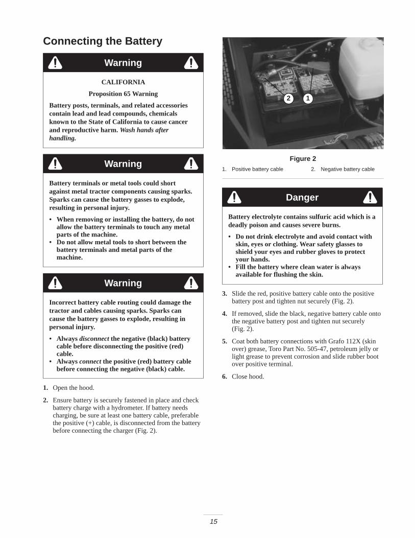
2. Ensure battery is securely fastened in place and checkbattery charge with a hydrometer. If battery needscharging, be sure at least one battery cable, preferablethe positive (+) cable, is disconnected from the batterybefore connecting the charger (Fig. 2).
2 1
Figure 21. Positive battery cable 2. Negative battery cable
Danger
Battery electrolyte contains sulfuric acid which is adeadly poison and causes severe burns.
• Do not drink electrolyte and avoid contact withskin, eyes or clothing. Wear safety glasses toshield your eyes and rubber gloves to protectyour hands.
• Fill the battery where clean water is alwaysavailable for flushing the skin.
3. Slide the red, positive battery cable onto the positivebattery post and tighten nut securely (Fig. 2).
4. If removed, slide the black, negative battery cable ontothe negative battery post and tighten nut securely(Fig. 2).
5. Coat both battery connections with Grafo 112X (skinover) grease, Toro Part No. 505-47, petroleum jelly orlight grease to prevent corrosion and slide rubber bootover positive terminal.
6. Close hood.

16
Mounting the Hood Latch1. Remove plug from hole in left front corner of hood
(Fig. 3).
2. Open the hood.
1
Figure 31. Hood plug
3. Mount locking latch to hood with lock washer and nut.Position switch with latch toward front of machine(Fig. 4).
4. Loosely mount latch strap to radiator support with 2capscrews (1/4 x 3/4 inch), flat washers and locknuts(Fig. 4).
2
1
3
Figure 41. Locking latch2. Latch bracket
3. Latch strap
5. Adjust latch bracket, until aligned with locking latch,then tighten capscrews.
6. Rotate latch to locked and unlocked position with key.Remove key and store in memorable place (Fig. 4).
7. Close the hood.
Replacing the Floor PanelFastener (Required for CE)
1. Remove fastener securing left front corner of floorpanel to frame (Fig. 5).
2. Replace with a flange head capscrew (5/16 x 5/8 inch)supplied in loose parts (Fig. 5).
1
Figure 51. Floor panel
Checking the Tire PressureThe tires are over–inflated for shipping. Therefore, releasesome of the air to reduce the pressure. Correct air pressurein the front and rear tires is 10-15 psi.
Important Maintain even pressure in all tires to assureuniform contact with turf.
Installing the Cutting UnitsCutting unit models 03860, 03861, and 03862 can beinstalled at any of the five mounting locations on thetraction unit.
Figure 6 shows the orientation of the hydraulic drive motorfor each of the five locations. For any of the locationsrequiring the motor to be mounted on the right end of thecutting unit, install a counter weight on the left end of thecutting unit. For the locations requiring the motor to bemounted on the left end, install a counter weight on theright end of the cutting unit.

17
Motor Weight
Motor Weight Weight Motor
Weight Motor Weight Motor
#1#4 #5
#3#2
Figure 6
Note: Counter weight mounting capscrews are shippedinstalled on the right bearing housing of the cutting units.The capscrews on left bearing housing are to be used forsecuring the hydraulic motor.
1. Remove cutting units from cartons. Assemble andadjust per Cutting Unit Operator’s Manual.
2. Remove protective plugs from each end of cutting unit.
3. Lubricate and install a large O-ring into bearing housinggroove on each end of cutting unit (Fig. 7 & 10).
Note: Before installing cutting unit motors, lubricateinternal splines of cutting unit reel shafts with grease.
4. Install a counter weight onto appropriate end of eachcutting unit with capscrews provided (Fig. 7).
12
3
Figure 71. Bearing housing2. O–ring—large
3. Counterweight
5. Thoroughly grease the cutting unit reel bearings prior toinstallation on the traction unit. Grease should beevident at the inboard reel seals. Refer to Cutting UnitOperator’s Manual for greasing procedure.
6. Insert a thrust washer onto horizontal shaft of pivotknuckle as shown in Figure 8.
12
3
5
4
Figure 81. Carrier frame2. Pivot knuckle3. Lift arm steering plate
4. Lynch pin5. Steering pin
7. Insert the horizontal shaft of the pivot knuckle into themounting tube of the carrier frame (Fig. 8).
8. Secure pivot knuckle to carrier frame with a thrustwasher, flat washer and a flange head capscrew (Fig. 8).
9. Insert a thrust washer onto vertical shaft of pivotknuckle (Fig. 8).
10.If removed, Insert the vertical shaft of the pivot knuckleinto lift arm pivot hub (Fig. 8). Guide the pivot knucklein place between the two rubber centering bumpers inthe under side of the lift arm steering plate.
11. Insert the lynch pin into the cross hole on the pivotknuckle shaft (Fig. 8).
12.On front center cutting unit, remove nut securing turfcompensation spring mounting bracket to left cuttingunit stabilizer ear (Fig. 9). Insert left tipper chain ontocapscrew and secure with nut removed.
13.Secure the right tipper chain to right cutting unitstabilizer ears with a capscrew (3/8 x 1 inch) and flangenut supplied in loose parts (Fig. 9).

18
1
2
3
Figure 91. Lift chains2. Turf compensation
mounting bracket
3. Cutting unit stabilizer ear
14.Mount the motor to the drive end of the cutting unit andsecure with two capscrews provided (Fig. 10).
1
2
Figure 101. Motor 2. O–ring
Note: If fixed cutting unit position is required, insertsteering pin into pivot knuckle mounting hole (Fig. 8).Hook spring wire around bottom of steering pin.
Alternate the AdjustmentsTraction units are setup at the factory appropriately formost fairway mowing applications.
The following adjustments are available for fine–tuning ofthe machine to the application:
Adjusting the Turf Compensation Spring
The Turf Compensation Spring (Fig. 11), connecting carrierframe to cutting unit, controls the amount of fore–aftrotation available, as well as the amount of groundclearance in transport and turn around.
The Turf Compensation Spring also transfers weight fromthe front to rear roller. (This helps to reduce a wave patternin the turf, also known as bobbing.)
Important Make spring adjustments with cutting unit ismounted to traction unit and lowered to shop floor. Refer toTraction Unit Operator’s Manual for mounting instructions.
1. Tighten lock nut on rear of spring rod until the gap Cbetween rear of spring bracket and front of washer is1 inch (26 mm) (Fig. 11).
2. Tighten hex nuts on front end of spring rod until thecompressed length A of spring is 8 inches (203 mm)(Fig. 11).
Note: When cutting rough or undulating turf, increasecompressed length A of the spring to 8-1/2 inch (216 mm)and gap C between rear of spring bracket and front ofwasher to 1–1/2 inches (39 mm) (Fig. 11).
Note: As compressed spring length A decreases, weighttransfer from front roller to rear roller increases and carrierframe/cutting unit rotation angle B decreases.
Note: As gap C between spring bracket and washerincreases, cutting unit ground clearance decreases andcarrier frame/cutting unit rotation angle B increases.
C
A
B
Figure 11
Lifted Height of Outer Front Cutting Units(Enable Position)
The turnaround height of the front outer cutting units(Number 4 & 5) may be increased to provide additionalground clearance on contoured fairways. Contact yourdistributor for assistance.
Note: The RM CONFIG time delay should not be changedfrom the original setting of 0 when using this method toadjust turn around height.
To increase the turn around height of the front cutting unitsproceed as follows:
• Position machine on a level surface, lower the cuttingunits and stop the engine.

19
• Loosen the carriage bolt nut securing the lift arm switchbracket to the #4 lift arm (left front) (Fig. 12).
1
2
3
Figure 121. Lift arm switch2. Carriage bolt nut
3. Lift arm flag
• Move the lift switch bracket up in the slot to the desiredposition.
• Set the distance between the lift arm switch and the flagon the lift arm to to approximately .062 inches.
• Tighten carriage bolt nut.
Adjusting the Cutting UnitStabilizerThe stabilizer for the front center cutting unit can beadjusted up or down to stabilize the cutting unit when in thefully raised position.
1. Raise all cutting units to the transport position and shutoff the engine.
2
1
3
Figure 131. Cutting unit stabilizer2. Stabilizer saddle
3. Carrier frame
2. On front center cutting unit, loosen the carriage boltsand nut securing the stabilizer saddle to stabilizer(Fig. 13).
3. Slide saddle down until it contacts cutting unit carrierframe. Tighten carriage bolts and nuts.
Note: Additional holes are provided to further adjust, ifrequired.
Rear BallastModel 03550 (2 Wheel Drive) complies with the CENstandard EN 836:1997, ISO standard 5395:1990 and theANSI B71.4–1999 Standard when 100 lbs. (45 kg) ofcalcium chloride ballast is added to rear wheels and rearweight kit (Part No. 104–1478) is installed.
Model 03551 (4 Wheel Drive) complies with the CENstandard EN 836:1997, ISO standard 5395:1990 and ANSIB71.4–1999 Standard when 100 lbs. (45 kg) of calciumchloride ballast is added to rear wheels.
Important If a puncture occurs in a tire with calciumchloride, remove unit from turf area as quickly as possible.To prevent possible damage to turf, immediately soakaffected area with water.

20
Before OperatingNote: Determine the left and right sides of the machinefrom the normal operating position.
Before servicing or making adjustments to
the machine, stop the engine and remove the
key from the switch. Lower the cutting units
to the ground.
Warning
Checking the Engine OilCrankcase capacity is 128 ounces (3.8 l) with filter.
1. Park machine on a level surface, stop engine andremove key from ignition switch. Open the hood.
2. Remove dipstick, wipe clean and reinstall dipstick.Remove dipstick and check oil level on dipstick; Oillevel should be up to the full mark (Fig. 14).
1
2
Figure 141. Dip stick 2. Oil fill cap
3. If oil is below full mark, remove fill cap and add SAE10W–30 CD, CE, CF, CF–4 or CG–4 classification oiluntil level reaches full mark on dipstick (Fig. 14). Donot over fill. Crankcase capacity is 128 ounces (3.8 l)with filter.
4. Install oil fill cap and close hood.
Checking the Cooling SystemClean debris off screen, oil cooler and front of radiatordaily, more often if conditions are extremely dusty anddirty. Refer to Servicing the Engine Cooling System,page 38.
The cooling system is filled with a 50/50 solution of waterand permanent ethylene glycol anti–freeze. Check level ofcoolant in expansion tank at beginning of each day beforestarting the engine. Capacity of cooling system is307 ounces.
If the engine has been running, pressurized hotcoolant can escape and cause burns if the radiatorcap is removed.
Allow the engine to cool at least 15 minutes or untilthe radiator cap is cool enough to touch withoutburning hands.
Caution
5. Check level of coolant in expansion tank. Coolant levelshould be between the marks on side of tank (Fig. 15).
1
Figure 151. Expansion tank
6. If coolant level is low, remove expansion tank cap andreplenish the system. Do not over fill.
7. Install expansion tank cap.

21
Filling the Fuel Tank
Danger
Under certain conditions, diesel fuel and fuelvapors are highly flammable and explosive. A fireor explosion from fuel can burn you and othersand can cause property damage.
• Use a funnel and fill the fuel tank outdoors, inan open area, when the engine is off and is cold.Wipe up any fuel that spills.
• Do not fill the fuel tank completely full. Add fuelto the fuel tank until the level is 1 in. (26 mm)below the bottom of the filler neck. This emptyspace in the tank allows the fuel to expand.
• Never smoke when handling fuel, and stay awayfrom an open flame or where fuel fumes may beignited by a spark.
• Store fuel in a clean, safety-approved containerand keep the cap in place.
1. Remove fuel tank cap (Fig. 16).
2. Fill tank to about 1 inch (26 mm) below top of tank, notfiller neck with No. 2 diesel fuel. Then install cap(Fig. 16).
1
Figure 161. Fuel tank cap
Checking the TransmissionFluidThe front axle housing acts as the reservoir for the system.The transmission and axle housing are shipped from thefactory with approximately 160 ounces of Mobil 424hydraulic fluid. However, check level of transmission oilbefore engine is first started and daily thereafter.
1
Figure 171. Transmission dipstick cap
3. Screw dipstick filler cap finger–tight onto filler neck(Fig. 17). It is not necessary to tighten cap with awrench.
Checking the Hydraulic FluidThe machines reservoir is filled at the factory withapproximately 8–1/2 gallons of high quality hydraulic fluid.
Check the level of hydraulic fluid before the engine isfirst started and daily thereafter. Appropriate hydraulicoils are listed below.
The following list is not assumed to be all–inclusive.Hydraulic fluids produced by other manufacturers may beused if they can cross reference to find an equivalent to theproducts listed. Toro will not assume responsibility fordamage caused by improper substitutions, so use onlyproducts from reputable manufacturers who will standbehind their recommendation.
Universal Tractor Hydraulic Fluid
Mobil Mobil Fluid 424
Amoco 1000 Fluid
Chevron Tractor Hydraulic Fluid
Conoco Power–Tran 3
Exxon Torque Fluid
Pennzoil Hydra–Tranz
Shell Donax TD
Texaco TDH
Note: Many hydraulic fluids are almost colorless, making itdifficult to spot leaks. A red dye additive for the hydraulicsystem oil is available in 2/3 oz. (20 ml) bottles. One bottleis sufficient for 4–6 gallons (15–22 1) of hydraulic oil.Order part no. 44–2500 from your authorized Torodistributor.
1. Position machine on a level surface, lower the cuttingunits and stop the engine.

22
2. Clean area around filler neck and cap of hydraulic tank.Remove cap from filler neck (Fig. 18).
1
Figure 181. Hydraulic tank cap
3. Remove dipstick from filler neck and wipe it with aclean rag. Insert dipstick into filler neck; then remove itand check level of fluid. Fluid level should be within1/4 inch (6 mm) of mark on dipstick.
4. If level is low, add appropriate fluid to raise level to fullmark.
5. Install dipstick and cap onto filler neck.
Checking the Rear AxleLubricant (Model 03551 Only)
The rear axle has three separate reservoirs which use SAE80W-90 wt. gear lube. Although the axle is shipped withlubricant from the factory, check the level before operatingthe machine.
1. Position the machine on a level surface.
2. Remove check plugs (3) from axle and make surelubricant is up to bottom of each hole(Figures 19 and 20).
3. If level is low, remove center fill plug and add enoughlubricant to bring the level up to the bottom of thecenter check plug hole (Figures 19 and 20).
4. Remove each end check plug and add enough lubricantto bring the level up to the bottom of each check plughole.
5. Install all the plugs.
1 1
2
Figure 191. Check plug 2. Fill plug
1
Figure 201. Left check plug—rear part
of axle
Checking the Reel to BedknifeContactEach day before operating, check reel to bedknife contact,regardless if quality of cut had previously been acceptable.There must be light contact across the full length of the reeland bedknife (refer to Adjusting Reel to Bedknife inCutting Unit Operator’s Manual).
Check the Torque of the WheelNutsTighten wheel nuts to 45–55 ft-lb (61–75 N�m) after1 to 4 hours of operation and again after 10 hours ofoperation and every 250 hours thereafter.

23
Failure to maintain proper torque of the wheelnuts could result in personal injury.
Torque the front wheel nuts and rear wheel bolts to45-55 ft-lb after 1–4 hours of operation andagain after 10 hours of operation. Torque every250 hours thereafter.
Warning
OperationNote: Determine the left and right sides of the machinefrom the normal operating position.
ControlsAdjusting the Seat
Seat adjusting lever allows 4 inches (102 mm) fore and aftadjustment. To adjust seat fore and aft, pull lever on leftside of seat assembly outward (Fig. 21). After moving seatto desired location, release lever to lock seat into position.
Seat adjusting knob adjusts seat for operators weight. Toadjust for operators weight, turn spring tension knob;clockwise to increase tension, counterclockwise to decreasespring tension (Fig. 21).
2
1
Figure 211. Seat adjusting lever 2. Seat adjusting knob
Traction Pedal
Controls forward and reverse operation. Depress top ofpedal to move forward and bottom to move backward(Fig. 22). Ground speed depends on how far pedal isdepressed. For no load, maximum ground speed, fullydepress pedal while throttle is in the fast position. To stop,reduce foot pressure on traction pedal and allow it to returnto center position.
1
Figure 221. Traction pedal
Brake Pedals
Two foot pedals operate individual wheel brakes for turningassistance, parking and to aid in obtaining better sidehilltraction. Locking pin connects the pedals for parking brakeoperation and transport (Fig. 23).
Parking Brake Latch
A knob on the left side of console actuates parking brakelock. To engage parking brake, connect pedals with lockingpin, push down on both pedals and pull parking brake latchout. To release parking brake, depress both pedals untilparking brake latch retracts (Fig. 23).
1
2
34
5
76
Figure 231. Forward speed limiter2. Reel control light3. Speedometer4. Brake pedals
5. Parking brake latch6. Locking pin7. Key switch
Traction Speed Limiter
Preset this lever to limit the amount the traction pedal canbe depressed in the forward direction to maintain a constantmowing speed (Fig. 23).
Reel Control Light
When lit, indicates a control system problem. Light blinkswhen glow plugs are preheating (Fig. 23).

24
Key Switch
Three positions: Off , On/Preheat and Start (Fig. 23).
Speedometer
Indicates ground speed at which machine is traveling(Fig. 23).
Lower Mow/Raise Control Lever
The lever raises and lowers the cutting units and also startsand stops the reels (Fig. 24).
Fuel Gauge
Shows amount of fuel in tank (Fig. 24).
Engine Oil Pressure Warning Light
Indicates dangerously low engine oil pressure (Fig. 24).
1
2 54 3
7 6
8 9
Figure 241. Lower mow/Raise control
lever2. Fuel gauge3. Engine coolant
temperature gauge4. Engine oil pressure
warning light
5. Engine coolanttemperature warning light
6. Glow plug indicator light7. Charge indicator8. Throttle control9. Enable/Disable switch
Engine Coolant Temperature WarningLight
The light illuminates and engine shuts down when coolantreaches a dangerously high temperature (Fig. 24).
Glow Plug Indicator Light
When lit, indicates glow plugs are on (Fig. 24).
Charge Indicator
Illuminates when system charging circuit malfunctions(Fig. 24).
Throttle Control
Move control forward to increase engine speed, rearward todecrease speed (Fig. 24).
Enable/Disable Switch
Used in conjunction with lower mow / raise control lever(Joystick) to operate reels. Reels can be raised but notlowered when in mid position (Fig. 24).
Backlap Knobs
Used in conjunction with lower mow / raise control leverfor backlapping operation (Fig. 24). Refer to Backlappingon page 49.
Reel Speed Controls
Controls RPM of front and rear cutting units (Fig. 25). #1position is for backlapping. Remaining settings are formowing operations. See section in manual for operatinginstructions and decal under seat for proper settings.
2
1
2
1
Figure 251. Reel speed controls 2. Backlap knobs

25
Hour Meter
(Located under control panel) shows total hours thatmachine has been operated.
Before servicing or making adjustments to
the machine, stop the engine and remove the
key from the switch. Lower the cutting units
to the ground.
Warning
Starting and StoppingImportant The fuel system must be bled if any of the
following situations have occurred. Refer to Bleeding theFuel Sysetm, page 25.
A. Initial start up of a new machine.
B. Engine has ceased running due to lack of fuel.
C. Maintenance has been performed upon fuel systemcomponents; i.e., filter replaced, separator serviced,etc.
1. Sit on the seat, keep foot off traction pedal. Assureparking brake is engaged, traction pedal is in Neutral,throttle is in Fast position and the Enable/Disableswitch is in the Disable position.
2. Turn ignition switch to On/Preheat position. Anautomatic timer will control preheat for 6 seconds.After preheat, turn key to start position. Do not crankthe engine or longer than 15 seconds. Release keywhen engine starts. If additional preheat is required,turn key to off position then to On/preheat position.Repeat process as required.
3. Run engine at idle speed or partial throttle until enginewarms up.
Note: Move throttle to fast position when restarting awarm engine.
4. To stop, move all controls to neutral and set parkingbrake. Return throttle to the idle position, turn key to offand remove it from the switch.
Bleeding the Fuel System1. Raise hood over engine.
2. Open the air bleed screw on the fuel injection pump(Fig. 26) with a 12 mm wrench.
1
Figure 261. Fuel injection pump bleed screw
3. Turn key in ignition switch to the on position. Electricfuel pump will begin operation, thereby forcing air outaround air bleed screw. Leave key in the on positionuntil solid stream of fuel flows out around screw.Tighten screw and turn key to off.
Danger
Under certain conditions, diesel fuel and fuelvapors are highly flammable and explosive. A fireor explosion from fuel can burn you and othersand can cause property damage.
• Use a funnel and fill the fuel tank outdoors, inan open area, when the engine is off and is cold.Wipe up any fuel that spills.
• Do not fill the fuel tank completely full. Add fuelto the fuel tank until the level is 1 inch (26 mm)below the bottom of the filler neck. This emptyspace in the tank allows the fuel to expand.
• Never smoke when handling fuel, and stay awayfrom an open flame or where fuel fumes may beignited by a spark.
• Store fuel in a clean, safety-approved containerand keep the cap in place.
Note: Normally, engine should start after above bleedingprocedures are followed. However, if engine does not start,air may be trapped between injection pump and injectors;refer to Bleeding Air From Injectors, page 38.
Setting the Reel SpeedTo achieve a consistent, high quality–of–cut and a uniformafter cut appearance, it is important that the reel speedcontrols (located under seat) be correctly set.
Adjust the reel speed controls as follows:
1. Select the height-of-cut at which the cutting units areset.
2. Choose the desired ground speed best suited forconditions.

26
3. Using the appropriate graph (See figure 27) for 5, 7 or11 blade cutting units, determine the proper reel speedsetting.
Figure 27
4. To set reel speed, rotate knobs (Fig. 28) until indicatorarrows are in line with the number designating desiredsetting.
2
1
2
1
Figure 281. Backlap knobs 2. Reel speed control
5. Operate the machine for several days, then examine thecut to ensure satisfaction with the quality of cut. The reelspeed selector knobs may be set one position on either sideof the position indicated on the chart to account fordifferences in grass condition, grass length removed, andpersonal preference of the superintendent. For a cut withmore grass removed but slightly more clip visibility, movethe reel speed selector knobs one position lower thanspecified. For a cut with less grass removed and slightlyless clip visibility, move the reel speed selector knobs oneposition higher than specified.
Note: Reel speed can be increased or decreased tocompensate for turf conditions.
Adjusting the Rear Lift ArmCounterbalanceThe counterbalance spring on the rear cutting unit lift armscan be adjusted to compensate for different turf conditions.Decreased counterbalance will help keep the cutting unitson the ground when mowing at higher speeds and helpsmaintain a uniform height-of-cut in rough conditions or inareas of thatch build up. Each counterbalance spring maybe adjusted to one of three settings. Each incrementincreases or decreases down pressure on the cutting unitsby 2 lbs.
1. Position machine on a level surface, lower the cuttingunits, stop the engine, engage the parking brakes andremove key from ignition switch.
Springs are under tension, use caution when
adjusting.
Warning

27
2
1
3
Figure 291. Counterbalance spring2. Spring bolt
3. Adjustment locations
2. Remove the capscrew and locknut while relievingspring tension (Fig. 29).
3. Move spring bolt to desired location and installcapscrew and locknut, while relieving spring tension(Fig. 29).
Towing the Traction UnitIf it becomes necessary to tow the machine, tow it forwardonly, for a short distance and at a speed no greater than3 mph.
Note: If these towing limits are exceeded, severe damage tothe hydrostatic transmission will occur.
1. Loosen and remove capscrews securing the drive shaftto the engine drive coupler. Loosen capscrews clampingdrive shaft to transmission (Fig. 30). Remove driveshaft.
1
Figure 301. Drive shaft
Important If drive shaft is not removed before towing,the transmission input shaft will not be able to rotate, thusnot allowing the transmission to maintain its internallubrication. Severe damage to the hydrostatic transmissionwill occur.
2. Attach a suitable chain, strap or cable to the center ofthe front frame member (Fig. 31).
1
Figure 311. Center of front frame member
Note: Lock both brake pedals together before towing.
3. Attach the other end of the towing device to a vehiclethat is capable of towing the machine safely and atspeeds below 3 mph.
4. An operator must be on the machine to steer it and keepthe traction pedal fully depressed in the forwardposition while towing.
5. When towing is completed, reinstall driveshaft asshown in Figure 30. The splines are designed to allowassembly only when the two halves of the shaft areproperly oriented.
Diagnostic LightThe RM 5500–D is equipped with a diagnostic light whichindicates if the electronic controller is functioning correctly.The green diagnostic light is located under the controlpanel, next to the fuse block. When the electronic controlleris functioning correctly and the key switch is moved to theon position, the controller diagnostic light will beilluminated. The light will blink if the controller detects amalfunction in the electrical system. The light will stopblinking and automatically reset when the key switch isturned to the off position.
1
Figure 321. Electronic controller light
When the controller diagnostic light blinks, one of thefollowing problems has been detected by the controller:
A. One of the outputs has been shorted.

28
B. One of the outputs is open circuited.
Using the diagnostic display, determine which output ismalfunctioning; refer to Checking Interlock Switches,page 28.
If the diagnostic light is not illuminated when the keyswitch is in the on position, this indicates that the electroniccontroller is not operating. Possible causes are:
• Loopback is not connected.
• The light is burned out.
• Fuses are blown.
• No battery power.
Check electrical connections, input fuses and diagnosticlight bulb to determine malfunction. Make sure loopbackconnector is secured to wire harness connector.
Diagnostic ACE DisplayThe RM 5500–D is equipped with an electronic controllerwhich controls most machine functions. The controllerdetermines what function is required for various inputswitches (i.e. seat switch, key switch, etc.) and turns on theoutputs to actuate solenoids or relays for the requestedmachine function. For the electronic controller to controlthe machine as desired, each of the input switches, outputsolenoids and relays must be connected and functioningproperly. The Diagnostic ACE display is a tool to help theuser verify correct electrical functions of the machine.
Checking the InterlockSwitchesThe purpose of the interlock switches are to prevent theengine from cranking or starting unless the traction pedal isin neutral, the Enable/Disable switch is in disable and theLower Mow/Raise control is in the neutral position. Inaddition, the engine will stop when the traction pedal isdepressed with operator off the seat or when parking brakeis engaged.
If safety interlock switches are disconnected ordamaged the machine could operate unexpectedlycausing personal injury.
• Do not tamper with the interlock switches.• Check the operation of the interlock switches
daily and replace any damaged switches beforeoperating the machine.
• Replace switches every two years regardless ofwhether they are operating properly or not.
Caution
Verifying the Interlock Switch Function
1. Park machine on a level surface, lower the cutting units,stop the engine and engage the parking brake.
2. Open control panel cover. Locate wire harness andconnectors near controller. Carefully unplug loop backconnector from harness connector.
1
Figure 331. Wire harness and connectors
3. Connect the Diagnostic ACE display connector to theharness connector. Make sure correct overlay decal ispositioned on Diagnostic ACE display.
4. Turn the key switch to the on position, but do not startmachine.
1
Figure 341. Diagnostic Ace
Note: The red text on the overlay decal refers to inputswitches and the green text refers to outputs.
5. The inputs displayed LED, on lower right column ofthe Diagnostic ACE, should be illuminated. If theoutputs displayed LED is illuminated, press the togglebutton, on Diagnostic ACE, to change the LED toinputs displayed.

29
6. The Diagnostic ACE will illuminate the LED associatedwith each of the inputs when that input switch is closed.Individually, change each of the switches from open toclosed (i.e., sit on seat, engage traction pedal, etc.), andnote that the appropriate LED on Diagnostic ACE willblink on and off when corresponding switch is closed.Repeat on each switch that is it possible to be changedby hand.
7. If switch is closed and appropriate LED does not turnon, check all wiring and connections to switch and/orcheck switches with an ohm meter. Replace anydefective switches and repair any defective wiring.
The Diagnostic ACE also has the ability to detect whichoutput solenoids or relays are turned on. This is a quickway to determine if a machine malfunction is electrical orhydraulic.
Verifying Output Function
1. Park machine on a level surface, lower the cutting units,stop the engine and engage the parking brake.
2. Open control panel cover. Locate wire harness andconnectors near controller. Carefully unplug loopbackconnector from harness connector.
3. Connect the Diagnostic ACE connector to the harnessconnector. Make sure correct overlay decal is positionedon Diagnostic ACE.
4. Turn the key switch to the on position, but do not startmachine.
Note: The red text on the overlay decal refers to inputswitches and the green text refers to outputs.
5. The outputs displayed LED, on lower right column ofDiagnostic ACE, should be illuminated. If inputsdisplayed LED is illuminated, press the toggle button,on Diagnostic ACE, to change LED to outputsdisplayed.
Note: It may be necessary to toggle between inputsdisplayed and outputs displayed several times to do thefollowing step. To toggle back and forth, press togglebutton once. This may be done as often as required. Do nothold the button.
6. Sit on the seat and attempt to operate the desiredfunction of the machine. (If you need help verifying thecorrect input settings for each function, refer to theLogic Chart on page 27) The appropriate output LED’sshould illuminate to indicate that the ECU is turning onthat function.
Note: If any output LED is blinking, this indicates anelectrical problem with that output. Repair or replacedefective electrical parts immediately. To reset a blinkingLED, turn the key switch off, then back on.
If no output LED’s are blinking, but the correct outputLED’s do not illuminate, verify that the required inputswitches are in the necessary positions to allow thatfunction to occur. Verify correct switch function.
If the output LED’s are on as specified, but the machinedoes not function properly, this indicates a non–electricalproblem. Repair as necessary.
Note: Due to electrical system constraints, the outputLED’s for start, preheat and etr/alt may not blink eventhough an electrical problem may exist for those functions.If the machine problem appears to be with one of thesefunctions, be certain to check the electrical circuit with avolt/ohm meter to verify that no electrical problem exists tothese functions.
If each output switch is in the correct position andfunctioning correctly, but the output LED’s are notcorrectly illuminated, this indicates an ECU problem. If thisoccurs, contact your Toro Distributor for assistance.
Important The Diagnostic ACE display must not beleft connected to the machine except for trouble shooting. Itis not designed to withstand the environment of themachine’s every day use. When done using DiagnosticACE, disconnect it from the machine and reconnectloopback connector to harness connector. Machine will notoperate without loopback connector installed on harness.Store the Diagnostic ACE in dry, secure location in shop,not on machine.
Hydraulic Valve SolenoidFunctionsUse the list below to identify and describe the differentfunctions of the solenoids in the hydraulic manifold. Eachsolenoid must be energized to allow function to occur.
Solenoid Function
MSV1 Front reel circuit
MSV2 Rear reel circuit
SV4 Lift front wing cutting units
SV3 Lift front center cutting unit
SV5 Lift rear cutting units
SV1 Lower any cutting units
SV1,SV2 Lift any cutting units

30
Operating Characteristics
Becoming Familiar with the Machine
Before mowing grass, practice operating machine in anopen area. Start and stop the engine. Operate in forwardand reverse. Lower and raise cutting units and engage anddisengage reels. When you feel familiar with the machine,practice operating up and down slopes at different speeds.
The brakes can be used to assist in turning the machine.However, use them carefully, especially on soft or wetgrass conditions because the turf may be torn accidentally.Individual turning brakes may also be used to help maintaintraction. For example, in some slope conditions, the uphillwheel slips and loses traction. If this situation occurs,depress uphill turn pedal gradually and intermittently untilthe uphill wheel stops slipping, thus, increasing traction onthe downhill wheel.
Important When operating machine, always use theseat belt and ROPS together.
Warning System
If a warning light comes on during operation, stop themachine immediately and correct the problem beforecontinuing operation. Serious damage could occur if themachine is operated with a malfunction.
Running the Mower
Start engine and move throttle to fast so engine is runningat maximum speed. Move the enable/disable switch toenable and use the lower mow/raise lever to control thecutting units (front cutting units are timed to lower beforethe rear cutting units). To move forward and cut grass,press traction pedal forward.
Transporting the mower
Move the enable/disable switch to joy stick disable andraise the cutting units to the transport position. Be carefulwhen driving between objects so you do not accidentallydamage the machine or cutting units. Use extra care whenoperating machine on slopes. Drive slowly and avoid sharpturns on slopes to prevent roll overs. The cutting unitsshould be lowered when going downhill for steeringcontrol.

31
MaintenanceNote: Determine the left and right sides of the machine from the normal operating position.
Recommended Maintenance Schedule
Maintenance ServiceInterval Maintenance Procedure
After first 10 hours
• Check the fan and alternator belt tension.
• Torque the wheel lug nuts.
• Change the transmission fluid.
• Replace the transmission filter.
After first 50 hours
• Change the engine oil and filter.
• Check the engine RPM (idle and full throttle).
• Torque the head and adjust valves.
After first 200 hours • Change the planetary gear oil
Every 50 hours
• Change the engine oil.
• Lubricate all grease fittings.
• Check the air cleaner.1
• Check the battery fluid level and cable connections.
Every 100 hours
• Change the engine oil filter.
• Inspect the cooling system hoses.
• Check the fan and alternator belt tension.
Every 200 hours
• Drain moisture from hydraulic tank.
• Drain moisture from fuel tank.
• Torque the wheel lug nuts.
• Check the reel bearing preload.
Every 400 hours
• Service the air cleaner.1
• Replace the fuel/water separator filter.
• Replace the fuel filter.
• Inspect traction linkage movement
• Check the engine RPM (idle and full throttle).
• Torque the head and adjust valves.
Every 800 hours
• Change the hydraulic fluid
• Check rear wheel toe-in.
• Pack the 2 WD rear wheel bearings.
• Change the 4 WD rear axle lubricant.
• Change the transmission fluid.
Every 1600 hours orevery 2 years,
whichever occurs first
• Replace all moving hoses.
• Replace interlock safety switches.
• Flush/replace the cooling system fluid.
• Drain/flush fuel tank.
• Drain/flush hydraulic tank.
1Service air cleaner whenever indicator shows red
32
Important Refer to your engine operator’s manual for additional maintenance procedures.
Lubricating the Mower
Before servicing or making adjustments to
the machine, stop the engine and remove the
key from the switch. Lower the cutting units
to the ground.
Warning
Greasing the Bearing and Bushings
The machine has grease fittings that must be lubricatedregularly with No. 2 General Purpose Lithium Base Grease.If machine is operated under normal conditions, lubricateall bearings and bushings after every 50 hours of operation.Lubricate bearings and bushings immediately after everywashing, regardless of the interval listed.
The grease fitting locations and quantities are:
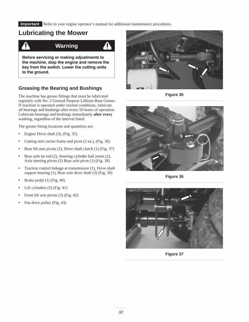
• Engine Drive shaft (3), (Fig. 35)
• Cutting unit carrier frame and pivot (2 ea.), (Fig. 36)
• Rear lift arm pivots (2), Drive shaft clutch (1) (Fig. 37)
• Rear axle tie rod (2), Steering cylinder ball joints (2),Axle steering pivots (2) Rear axle pivot (1) (Fig. 38)
• Traction control linkage at transmission (1), Drive shaftsupport bearing (1), Rear axle drive shaft (3) (Fig. 39)
• Brake pedal (1) (Fig. 40)
• Lift cylinders (5) (Fig. 41)
• Front lift arm pivots (3) (Fig. 42)
• Fan drive pulley (Fig. 43)
Figure 35
Figure 36
Figure 37

33
Figure 38
Figure 39
Figure 40
Figure 41
Figure 42
Figure 43

34
Service Interval Chart
Figure 44

35
Daily Maintenance ChecklistDuplicate this page for routine use.
For the week of:
Maintenance Check Item Mon. Tues. Wed. Thurs. Fri. Sat. Sun.
Safety Interlock Operation
Brake Operation
Engine Oil & Fuel Level
Cooling System Fluid Level
Drain Water/Fuel Separator
Air Filter Restriction Indicator
Radiator and Screen for Debris
Unusual Engine Noises1
Unusual Operating Noises
Transmission Oil Level
Hydraulic System Oil Level
Hydraulic Filter Indicator2
Hydraulic Hoses for Damage
Fluid Leaks
Tire Pressure
Instrument Operations
Reel–to–Bedknife Adjustment
Height–of–Cut Adjustment
Lubricate All Grease Fittings3
Touch–up Damaged Paint
1 Check glow plugs and injector nozzles, if excess smoke or rough running is noted.2 Check with engine running and oil at operating temperature.3 Immediately after every washing, regardless of the interval listed.
Servicing the Air Cleaner
Before servicing or making adjustments to
the machine, stop the engine and remove the
key from the switch. Lower the cutting units
to the ground.
Warning
1. Check air cleaner body for damage which couldpossibly cause an air leak. Replace a damaged aircleaner body.
2. Service the air cleaner filters when ever air cleanerindicator (Fig. 45) shows red or every 400 hours (morefrequently in extreme dusty or dirty conditions). Do notover service air filter.
3. Be sure cover is sealing around air cleaner body.
Servicing the Precleaner Bowl
Normally, inspect precleaner bowl daily. When conditionsare extremely dusty and dirty, inspect more frequently. Donot let dust or debris build up above level marks onprecleaner bowl.
1. Remove thumb screw, separate cover from precleanerbowl.

36
21
3
Figure 451. Air cleaner indicator2. Pre cleaner bowl
3. Dust cup
2. Empty precleaner bowl and wipe clean.
3. Assemble and install precleaner bowl, cover and thumbscrew.
Note: When operating machine in extremely dustyconditions, an optional extension tube(Toro Part No. 43-3810), which raises precleaner bowlabove hood, thus, lengthening the time between precleanerbowl servicing, is available from your local authorized ToroDistributor.
Cleaning the Air Filter
1. Release latches securing air cleaner cover to air cleanerbody. Separate cover from body. Clean inside of aircleaner cover.
2. Gently slide filter element out of air cleaner body toreduce the amount of dust dislodged. Avoid knockingfilter against air cleaner body.
1
Figure 461. Filter element
3. Inspect filter element and discard if damaged. Do notwash or reuse a damaged filter.
4. Blow compressed air from inside to the outside of dryfilter element. Do not exceed 40 psi to prevent damageto the element.
5. Keep air hose nozzle at least 2 inches (52 mm) fromfilter and move nozzle up and down while rotating thefilter element. Inspect for holes and tears by lookingthrough the filter toward a bright light.
6. Inspect new filter for shipping damage. Check sealingend of filter. Do not install a damaged filter.
7. Insert new filter properly into air cleaner body. Makesure filter is sealed properly by applying pressure toouter rim of filter when installing. Do not press onflexible center of filter.
8. Reinstall cover and secure latches.
9. Reset indicator (Fig. 45) if showing red.
Before servicing or making adjustments to
the machine, stop the engine and remove the
key from the switch. Lower the cutting units
to the ground.
Warning
Servicing the Engine Oil andFilterChange oil and filter initially after the first 50 hours ofoperation, thereafter change oil every 50 hours and filterevery 100 hours.
1. Remove drain plug and let oil flow into drain pan(Fig. 47). When oil stops, install drain plug.
1
Figure 471. Engine oil drain plug
2. Remove the engine oil filter (Fig. 48). Apply a lightcoat of clean oil to the new filter seal before screwing iton. Do not over–tighten.

37
1
Figure 481. Engine oil filter
3. Add oil to crankcase; refer to Checking the Engine Oil,page 20.
Servicing the Fuel SystemChanging the Fuel Tank
Drain and clean fuel tank every 2 years. Also, drain andclean tank if fuel system becomes contaminated or ifmachine is to be stored for an extended period. Use cleanfuel to flush out the tank.
Checking the Fuel Lines and Connections
Check lines and connections every 400 hours or yearly,whichever comes first. Inspect for deterioration, damage, orloose connections.
Servicing the Fuel Filter / Water Separator
Drain water or other contaminants from fuel filter / waterseparator (Fig. 49) daily.
1. Locate fuel filter, under hood, and place a cleancontainer under it.
2. Loosen drain plug on bottom of filter canister. Tightenplug after draining.
1
2
Figure 491. Fuel Filter/ Water
Separator2. Drain plug
Replace filter canister after every 400 hours of operation.
1. Clean area where filter canister mounts.
2. Remove filter canister and clean mounting surface.
3. Lubricate gasket on filter canister with clean oil.
4. Install filter canister by hand until gasket contactsmounting surface, then rotate an additional 1/2 turn.
Replacing the Fuel Pre FilterReplace the fuel pre filter after every 400 operating hoursor yearly, whichever occurs first.
1. Remove screw securing filter to frame rail.
2. Clamp both fuel lines that connect to the fuel filter sofuel cannot drain when lines are removed.
3. Loosen the hose clamps at both ends of the filter andpull fuel lines off filter.
4. Slide hose clamps onto ends of fuel lines. Push fuellines onto fuel filter and secure them with hose clamps.Be sure arrow on side of filter points toward theinjection pump.

38
1
22
Figure 501. Fuel filter 2. Hose clamp
Bleeding Air from the InjectorsNote: This procedure should be used only if fuel systemhas been purged of air through normal priming proceduresand engine will not start; refer to Bleeding Fuel System,page 25.
1. Loosen the pipe connection to the No. 1 nozzle andholder assembly.
1
Figure 511. Fuel injector
2. Move throttle to fast position.
3. Turn key in key switch to start position and watch fuelflow around connector. Engine will crank. Turn key tooff position when solid flow is observed.
4. Tighten pipe connector securely.
5. Repeat steps on remaining nozzles.
Servicing the Engine CoolingSystemRemoving Debris
Remove debris from screen, oil coolers and radiator daily,clean more frequently in dirty conditions.
1. Turn engine off and raise hood. Clean engine areathoroughly of all debris.
2. Loosen clamps and pull up on screen to slide it out ofmounting tracks (Fig. 52). Clean screen thoroughly withwater or compressed air.
1
Figure 521. Screen
3. Slightly raise oil coolers and pivot forward (Fig. 53).Clean both sides of oil coolers and radiator areathoroughly with compressed air. Pivot oil coolers backinto position.
4. Install screen and close hood.

39
2
1
3
Figure 531. Reel oil cooler2. Radiator
3. Transmission oil cooler
Servicing the Engine BeltsCheck condition and tension of all belts after first day ofoperation and every 100 operating hours thereafter.
Servicing the Alternator Belt
1. Open hood.
2. Check tension by depressing belt midway betweenalternator and crankshaft pulleys with 22 lb. (98 N) offorce. Belt should deflect 7/16 inch (11 mm) Ifdeflection is incorrect, proceed to step 3. If correct,continue operation.
1 2
Figure 541. Alternator belt 2. Brace
3. Loosen bolt securing brace to engine and bolt securingalternator to brace.
4. Insert pry bar between alternator and engine and pry outon alternator.
5. When proper tension is achieved, tighten alternator andbrace bolts to secure adjustment.
Servicing the Cooling Fan Belt
1. Loosen lock nut on belt tensioner lever.
2. Apply 5–10 lb. (22–44 N) of force at end of lever to setthe proper tension on the fan belt.
3. Tighten lock nut to secure adjustment.
2
1
Figure 551. Cooling fan belt 2. Tensioner lever

40
Adjusting the Throttle1. Position throttle lever forward so it stops against seat
base slot.
2. Loosen the throttle cable connector on the lever arm atthe injection pump.
3. Hold the injection pump lever arm against the high idlestop and tighten the cable connector.
Note: When tightened, the cable connector must be free toswivel.
4. Torque the lock nut, used to set the friction device onthe throttle lever, to 40–55 in-lb (5–6 N�m) Themaximum force required to operate the throttle levershould be 20 lb. (89 N).
1
Figure 561. Injection pump lever arm
Before servicing or making adjustments to
the machine, stop the engine and remove the
key from the switch. Lower the cutting units
to the ground.
Warning
Changing the Hydraulic FluidChange hydraulic fluid after every 800 operating hours, innormal conditions. If fluid becomes contaminated, contactyour local TORO distributor because the system must beflushed. Contaminated fluid looks milky or black whencompared to clean oil.
1. Turn engine off and set parking brake.
2. Remove drain plug from bottom of reservoir and lethydraulic fluid flow into drain pan. Reinstall andtighten plug when hydraulic fluid stops draining.
1
Figure 571. Hydraulic reservoir
3. Fill reservoir with approximately 8–1/2 gallons ofhydraulic fluid. Refer to Checking Hydraulic Fluid,page 21.
Important Use only hydraulic fluids specified. Otherfluids could cause system damage.
4. Install reservoir cap. Start engine and use all hydrauliccontrols to distribute hydraulic fluid throughout thesystem. Also check for leaks. Then stop the engine.
5. Check level of fluid and add enough to raise level tofull mark on dipstick. Do Not Over Fill.
Replacing the Hydraulic FilterThe hydraulic system filter head is equipped with a serviceinterval indicator. With the engine running, view theindicator, it should be in the green zone. When theindicator is in the red zone, the filter element should bechanged.
Use the Toro replacement filter (Part No. 94-2621).
Important Use of any other filter may void thewarranty on some components.
1. Position machine on a level surface, lower the cuttingunits, stop the engine, engage the parking brakes andremove key from ignition switch.
2. Clean area around filter mounting area. Place drain panunder filter and remove filter.

41
1
Figure 581. Hydraulic filter
3. Lubricate new filter gasket and fill the filter withhydraulic fluid.
4. Assure filter mounting area is clean. Screw filter onuntil gasket contacts mounting plate. Then tighten filterone–half turn.
5. Start engine and let run for about two minutes to purgeair from the system. Stop the engine and check forleaks.
Checking Hydraulic Lines AndHosesDaily, check hydraulic lines and hoses for leaks, kinkedlines, loose mounting supports, wear, loose fittings, weatherdeterioration and chemical deterioration. Make allnecessary repairs before operating.
Hydraulic fluid escaping under pressure canpenetrate skin and cause injury.
• If hydraulic fluid is injected into the skin it mustbe surgically removed within a few hours by adoctor familiar with this type of injury.Gangrene may result if this is not done.
• Keep body and hands away from pin hole leaksor nozzles that eject high pressure hydraulicfluid.
• Use cardboard or paper to find hydraulic leaks.• Safely relieve all pressure in the hydraulic
system before performing any work on thehydraulic system.
• Make sure all hydraulic fluid hoses and lines arein good condition and all hydraulic connectionsand fittings are tight before applying pressure tohydraulic system.
Warning
Using the Hydraulic SystemTest PortsThe test ports are used to test pressure in the hydrauliccircuits. Contact your local Toro distributor for assistance.
1. Test Port #1 is used to assist in trouble shooting thehydraulic circuit for the front cutting units and liftcylinders.
2
1
Figure 591. Test port number 1 2. Test port number 2
2. Test Port #2 is used to assist in trouble shooting thehydraulic circuit for the rear cutting units.
3. Test Port #3 is located on the rear of the hydrostatictransmission and is used to measure the charge pressureof the transmission.
4. Test Port #4 is located on the rear of the lift block and isused to assist in trouble shooting the hydraulic liftcircuit.
Adjusting Traction Drive ForNeutralThe machine must not creep when traction pedal isreleased. If it does creep, an adjustment is required.
1. Park machine on a level surface, shut engine off andlower cutting units to the floor. Depress only the rightbrake pedal and engage the parking brake.
2. Jack up left side of machine until front tire is off theshop floor. Support machine with jack stands to preventit from falling accidentally.
Note: On 4 wheel drive models, left rear tire must also beoff the shop floor or 4 wheel drive driveshaft must beremoved.
3. Under right side of machine, loosen locknut on tractionadjustment cam.

42
1
Figure 601. Traction adjustment cam
Engine must be running so final adjustment of
the traction adjustment cam can be
performed.
• To avoid possible personal injury, keephands, feet, face and other parts of thebody away from the muffler, other hot partsof the engine, and other rotating parts.
Warning
4. Start engine and rotate cam hex in either direction untilwheel ceases rotation.
5. Tighten locknut securing adjustment.
6. Stop the engine and release the right brake. Removejack stands and lower the machine to the shop floor.Test drive the machine to make sure it does not creep.
Adjusting the Cutting Unit DropRateThe cutting unit lift circuit is equipped with (3) adjustablevalves used to ensure the cutting units do not drop tooquickly and damage the turf. Adjust cutting units asfollows:
Adjusting the Center Cutting Unit
1. Locate valve behind access panel above operator’splatform (Fig. 61).
2. Loosen setscrew on valve and rotate valveapproximately 1/2 turn clockwise.
3. Verify drop rate adjustment by raising and loweringcutting unit several times. Readjust as required.
4. After desired drop rate is attained, tighten setscrew tolock adjustment.
1
Figure 611. Center cutting unit adjustment valve
Adjusting the Outside Front Cutting Units
1. Locate valve on right side of lift block (Fig. 62).
2. Loosen setscrew on valve. Rotate valve 1/2 turnclockwise.
3. Verify drop rate adjustment by raising and loweringcutting units several times. Readjust as required.
4. After desired drop rate is attained, tighten set screw tolock adjustment.
1
Figure 621. Outside front cutting unit adjustment valve

43
Adjusting the Rear Cutting Units
1. Raise hood and locate valve in center of machinebehind engine (Fig. 63).
1
Figure 631. Rear cutting unit adjustment valve
2. Loosen locking ring on valve and rotate valveapproximately 1/2 turn clockwise.
3. Verify drop rate adjustment by raising and loweringcutting units several times. Readjust as required.
4. After desired drop rate is attained, tighten locking ringto lock adjustment.
Checking and AdjustingTraction LinkageDue to normal wear in the control linkage and hydrostatictransmission, an increased amount of force may be requiredto return the transmission to neutral. Periodically check themachine.
Checking the Traction Linkage
1. On a large, flat open area, drive the machine at fullthrottle and full traction speed.
2. Remove foot from traction pedal and measure thedistance required for the machine to come to a stop.
3. If the distance required to stop is greater than 18 feet(5.5 meters) an adjustment to the traction linkage isrequired. Proceed to next step.
Adjusting the Traction Linkage
1. Park machine on a level surface, lower cutting units tothe floor and shut engine off.
2. Connect brake pedals together with locking pin, pushboth pedals down and pull parking brake latch out.
3. Loosen outer hex nut securing eye bolt to spring anchorplate.
1
2 3
45
Figure 641. Spring anchor plate2. Eye bolt3. Inner locknut4. Outer locknut
5. Shorten the distance todecrease the timerequired to stop themachine
4. Rotate, clockwise, until distance between inside of eyebolt loop and inside of spring anchor plate is shortened1/8 inch (3 mm), as shown in figure 64. Tighten hexnut.
5. Operate the machine and check stopping distance.Repeat procedure if required.
Note: Shortening the distance between inside of eye boltloop and inside of spring anchor plate increases the pedalforce on the traction pedal. Therefore, do not over adjust.

44
Hydraulic Schematic

45
Before servicing or making adjustments to
the machine, stop the engine and remove the
key from the switch. Lower the cutting units
to the ground.
Warning
Adjusting the Service BrakesAdjust the service brakes when there is more than 1 inch(26 mm) of free travel of the brake pedal, or when thebrakes do not work effectively. Free travel is the distancethe brake pedal moves before braking resistance is felt.
1. Disengage locking pin from brake pedals so both pedalswork independently of each other.
2. To reduce free travel of brake pedals, tighten the brakes– loosen front nut on threaded end of brake cable. Thentighten rear nut to move cable backward until brakepedals have 1/2 to 1 inch (13 mm to 26 mm) of freetravel. Tighten front nuts after brakes are adjustedcorrectly.
1
Figure 651. Brake cables
Changing the TransmissionFluidChange the transmission fluid after every 800 hours ofoperation, in normal conditions.
1. Position machine on a level surface, lower the cuttingunits, stop the engine, engage the parking brakes andremove key from ignition switch.
2. Clean area around suction line on bottom oftransmission. Place drain pan under line.
1
2
Figure 661. Transmission suction line 2. Transmission oil filter
3. Remove line from transmission allowing fluid to draininto drain pan.
4. Reinstall suction line to transmission.
5. Fill with oil; refer to Checking the Transmission Fluid,page 21.
6. Before starting the engine after changing transmissionfluid, disconnect the run (ETR) solenoid on the engine,and crank the engine several times for 15 seconds. Thisallows the charge pump to fill the transmission withfluid before the engine is started.
Replacing the TransmissionFilterChange the transmission filter after the first 10 hours ofoperation and every 800 hours, thereafter.
Only the Toro replacement filter (Part No. 75-1330) can beused in the hydraulic system.
Important Use of any other filter may void thewarranty on some components.
1. Position machine on a level surface, lower the cuttingunits, stop the engine, engage the parking brakes andremove key from ignition switch.
2. Clean area around filter mounting area. Place drain panunder filter and remove filter.
3. Lubricate new filter gasket and fill the filter withhydraulic oil.
4. Assure filter mounting area is clean. Screw filter onuntil gasket contacts mounting plate. Then tighten filterone–half turn.

46
5. Start engine and let run for about two minutes to purgeair from the system. Stop the engine and check forleaks. Check fluid level and replenish if necessary.
Changing Rear Axle Lubricant(Model 03551 Only)
After every 800 hours of operation the oil in the rear axlemust be changed.
1. Position machine on a level surface.
2. Clean area around the drain plugs.
3. Remove plug allowing oil to drain into drain pans.
4. After oil is drained, apply thread locking compoundon drain plug threads and reinstall in axle.
11
Figure 671. Drain plug
5. Fill axle with lubricant; refer to Checking the Rear AxleLubricant, page 22.
Checking and Adjusting theRear Wheel Toe–InAfter every 800 operating hours or annually, check rearwheel toe-in.
1. Measure center-to-center distance (at axle height) atfront and rear of steering tires. Front measurement mustbe within ±1/8 inch (3 mm) of the rear measurement.
1
Figure 681. Tie rod
2. To adjust, loosen clamps at both ends of tie rod.
3. Rotate tie rod to move front of tire inward or outward.
4. Tighten tie rod clamps when adjustment is correct.
Servicing the Battery
CALIFORNIA
Proposition 65 Warning
Battery posts, terminals, and related accessoriescontain lead and lead compounds, chemicalsknown to the State of California to cause cancerand reproductive harm. Wash hands afterhandling.
Warning
Important Before welding on a machine, disconnectboth cables from the battery, disconnect both wire harnessplugs from the electronic control unit and the terminalconnector from the alternator to prevent damage to theelectrical system.
Battery terminals or metal tools could shortagainst metal tractor components causing sparks.Sparks can cause the battery gasses to explode,resulting in personal injury.
• When removing or installing the battery, do notallow the battery terminals to touch any metalparts of the machine.
• Do not allow metal tools to short between thebattery terminals and metal parts of themachine.
Warning

47
Incorrect battery cable routing could damage thetractor and cables causing sparks. Sparks cancause the battery gasses to explode, resulting inpersonal injury.
• Always disconnect the negative (black) batterycable before disconnecting the positive (red)cable.
• Always connect the positive (red) battery cablebefore connecting the negative (black) cable.
Warning
Note: Check battery condition weekly or after every50 hours of operation. Keep terminals and entire batterycase clean because a dirty battery will discharge slowly. Toclean the battery, wash the entire case with solution ofbaking soda and water. Rinse with clear water. Coat thebattery posts and cable connectors with Grafo 112X(skin–over) grease (Toro Part No. 505-47) or petroleumjelly to prevent corrosion.
Servicing the FusesThere are 6 fuses in the machines electrical system. Theyare located below control panel (Figures 69 and 70).
Figure 69
Figure 70
Adjusting the Parking BrakeSwitchThe parking brake uses a proximity sensor located underthe cover of the steering tower. This sensor is adjusted sothe sensor locates a flag on the latch rod when the parkingbrake is released.
Using the Ace Diagnostic tool verify the brake sensoropens and closes properly. The parking brake light on theDiagnostic tool should be on when engaged and off whendisengaged. If the light remains on when the parking brakeis released the engine will stop when the traction system isengaged. Should this condition exist adjust the sensor usingthe Diagnostic tool to verify its operation.
The adjustment is accomplished by moving the sensorwithin its slotted hole. The position of the flag on the latchrod is over the sensor target area when the parking brake isreleased. Ensure that in the engaged position the flag movesaway from the target zone of the sensor.
Installing Optional LightingImportant If optional lighting is be added to the
traction unit, use the following schematic and part numbersto prevent damage to the traction units electrical system.
Switch
Relay
Orange
Red
Black
2 3
86
85
30
87
To Lights w/external ground
To Lights
Schematic For Optional Lighting
Switch* RelayToro Part No. 75-1010Honeywell Part No. 1TL1-2
Toro Part No. 70-1480Bosch Part No. 0-332-204
* Punch out in control panel provided for switch installa-tion
Add 10 Amp fuse to fuse block at location shown
Black, red and orange wires are located in control con-sole.
Figure 71
Note: Make sure a good ground is achieved to preventdamage to traction unit.

48
Wiring Diagram

49
Backlapping
Danger
The reels may stall while backlapping and couldrestart suddenly. Contact with the reels duringbacklapping will cause personal injury.
• Never place hands or feet in the reel area whilethe engine is running.
• Never attempt to turn the reels by hand or footor touch the reels while backlapping.
• Never change engine speed while backlapping.Only backlap at idle speed.
• Stop the engine and move the desired reel speedselector knob(s) one position closer to “13.”
Note: When backlapping, the front units all operatetogether, and the rear units operate together.
1. Position the machine on a level surface, lower thecutting units, stop the engine, engage the parking brake,and move the Enable/Disable switch to disable position.
2. Unlock and raise the seat to expose controls.
3. Locate the reel speed selector knobs and backlap knobs(Fig. 72). Rotate the desired backlap knob(s) to thebacklap position and the desired reel speed selectorknob(s) to position 1.
1 1
2
2
Figure 721. Reel speed selector
knobs2. Backlap knobs
Note: Backlapping speed may be increased by moving thereel speed selector knob toward “13.” Each position willincrease speed approximately 100 rpm. After changingselector, wait 30 seconds for the system to stabilize at thenew speed.
4. Make initial reel to bedknife adjustments appropriatefor backlapping on all cutting units which are to bebacklapped.
5. Start engine and run at idle speed.
Contact with the reels or other moving parts canresult in personal injury.
• Keep finger, hands, and clothing away from thereels and other moving parts.
• Never use a short handles brush to applylapping compound.
Caution
6. Select either front, rear, or both backlap knobs todetermine which reels will be backlapped.
7. Move Enable/Disable switch to enable position. MoveLower Mow/Lift control forward to start backlappingoperation on designated reels.
8. Apply lapping compound with a long handle brush(Toro Part No. 29-9100). Never use a short handledbrush (Fig. 73).
1
Figure 731. Long handle brush
9. If reels stall or become erratic while backlapping, stopbacklapping by moving the Lower Mow/Lift controllever rearward. Once the reels have stopped, move thedesired reel speed selector knob(s) one position closerto 13. Resume backlapping by moving the LowerMow/Lift control lever forward.

50
10.To make an adjustment to the cutting units whilebacklapping, turn reels off by moving the LowerMow/Raise lever rearward; move the Enable/Disableswitch to disable and turn the engine off. Afteradjustments have been completed, repeat steps 5–9.
11.Backlap until the reels can cut paper.
Maintaining the Cutting Unit1. When the cutting unit is adequately sharpened, a burr
will form on the front edge of the knife. Using a file,carefully remove the burr without dulling the cuttingedge (Fig. 74).
Figure 74
2. Repeat procedure for all cutting units to be backlapped.
When backlap operation has been completed, return thebacklap knobs to the forward flow position, lower seat andwash all lapping compound off cutting units. Adjust cuttingunit reel to bedknife as needed.
Note: If the backlap knobs are not returned to the forwardflow position after backlapping, the cutting units will notraise or function properly.
51
StorageTraction Unit1. Thoroughly clean the traction unit, cutting units and the
engine.
2. Check the tire pressure. Inflate all traction unit tires to10–15 psi.
3. Check all fasteners for looseness; tighten as necessary.
4. Grease or oil all grease fittings and pivot points. Wipeup any excess lubricant.
5. Lightly sand and use touch–up paint on painted areasthat are scratched, chipped, or rusted. Repair any dentsin the metal body.
6. Service the battery and cables as follows:
A. Remove the battery terminals from the battery posts.
B. Clean the battery, terminals, and posts with a wirebrush and baking soda solution.
C. Coat the cable terminals and battery posts withGrafo 112X skin–over grease(Toro Part No. 505-47) or petroleum jelly to preventcorrosion.
D. Slowly recharge the battery every 60 days for24 hours to prevent lead sulfation of the battery.
Charging the battery produces gasses that canexplode.
Never smoke near the battery and keep sparks andflames away from battery.
Warning
Engine1. Drain the engine oil from the oil pan and replace the
drain plug.
2. Remove and discard the oil filter. Install a new oil filter.
3. Refill oil pan with 128 ounces of SAE10W-30 motoroil.
4. Start the engine and run at idle speed for approximatelytwo minutes.
5. Stop the engine.
6. Thoroughly drain all fuel from the fuel tank, lines andthe fuel filter/water separator assembly.
7. Flush the fuel tank with fresh, clean diesel fuel.
8. Re–secure all fuel system fittings.
9. Thoroughly clean and service the air cleaner assembly.
10.Seal the air cleaner inlet and the exhaust outlet withweatherproof tape.
11.Check anti–freeze protection and add as needed forexpected minimum temperature in your area.

The Toro General Commercial Products WarrantyA Two-Year Limited Warranty
Conditions and Products CoveredThe Toro Company and its affiliate, Toro Warranty Company,pursuant to an agreement between them, jointly warrant your ToroCommercial Product (“Product”) to be free from defects inmaterials or workmanship for two years or 1500 operationalhours*, whichever occurs first. Where a warrantable conditionexists, we will repair the Product at no cost to you includingdiagnosis, labor, parts, and transportation. This warranty beginson the date the Product is delivered to the original retail purchaser.
* Product equipped with hour meter
Instructions for Obtaining Warranty ServiceYou are responsible for notifying the Commercial ProductsDistributor or Authorized Commercial Products Dealer from whomyou purchased the Product as soon as you believe a warrantablecondition exists.
If you need help locating a Commercial Products Distributor orAuthorized Dealer, or if you have questions regarding yourwarranty rights or responsibilities, you may contact us at:
Toro Commercial Products Service DepartmentToro Warranty Company8111 Lyndale Avenue SouthBloomington, MN 55420-1196952-888-8801 or 800-982-2740E-mail: [email protected]
Owner ResponsibilitiesAs the Product owner, you are responsible for required mainte-nance and adjustments stated in your operator’s manual. Failureto perform required maintenance and adjustments can be groundsfor disallowing a warranty claim.
Items and Conditions Not CoveredNot all product failures or malfunctions that occur during thewarranty period are defects in materials or workmanship. Thisexpress warranty does not cover the following:
• Product failures which result from the use of non-Tororeplacement parts, or from installation and use of add-on,modified, or unapproved accessories
• Product failures which result from failure to perform requiredmaintenance and/or adjustments
• Product failures which result from operating the Product in anabusive, negligent or reckless manner
• Parts subject to consumption through use unless found to bedefective. Examples of parts which are consumed, or used up,during normal Product operation include, but are not limited to,blades, reels, bedknives, tines, spark plugs, castor wheels,tires, filters, belts, etc.
• Failures caused by outside influence. Items considered to beoutside influence include, but are not limited to, weather,storage practices, contamination, use of unapproved coolants,lubricants, additives, or chemicals, etc.
• Normal “wear and tear” items. Normal “wear and tear”includes, but is not limited to, damage to seats due to wear orabrasion, worn painted surfaces, scratched decals or win-dows, etc.
PartsParts scheduled for replacement as required maintenance arewarranted for the period of time up to the scheduled replacementtime for that part.
Parts replaced under this warranty become the property of Toro.Toro will make the final decision whether to repair any existing partor assembly or replace it. Toro may use factory remanufacturedparts rather than new parts for some warranty repairs.
General ConditionsRepair by an Authorized Toro Distributor or Dealer is your soleremedy under this warranty.
Neither The Toro Company nor Toro Warranty Company isliable for indirect, incidental or consequential damages inconnection with the use of the Toro Products covered by thiswarranty, including any cost or expense of providing substi-tute equipment or service during reasonable periods ofmalfunction or non-use pending completion of repairs underthis warranty. Except for the Emissions warranty referencedbelow, if applicable, there is no other express warranty. Allimplied warranties of merchantability and fitness for use arelimited to the duration of this express warranty.Some states do not allow exclusions of incidental or consequentialdamages, or limitations on how long an implied warranty lasts, sothe above exclusions and limitations may not apply to you.
This warranty gives you specific legal rights, and you may alsohave other rights which vary from state to state.
Note regarding engine warranty: The Emissions ControlSystem on your Product may be covered by a separate warrantymeeting requirements established by the U.S. EnvironmentalProtection Agency (EPA) and/or the California Air ResourcesBoard (CARB). The hour limitations set forth above do not apply tothe Emissions Control System Warranty. Refer to the EngineEmission Control Warranty Statement printed in your operator’smanual or contained in the engine manufacturer’s documentationfor details.
Countries Other than the United States or CanadaCustomers who have purchased Toro products exported from the United States or Canada should contact their Toro Distributor (Dealer)to obtain guarantee policies for your country, province, or state. If for any reason you are dissatisfied with your Distributor’s service orhave difficulty obtaining guarantee information, contact the Toro importer. If all other remedies fail, you may contact us at Toro WarrantyCompany.
Part No. 374-0031 Rev. a