
Reduction of Mutual Coupling in Neighboring Strip … · Reduction of Mutual Coupling in...
65
1 Alexander B. Yakovlev and Hossein M. Bernety Department of Electrical Engineering Center for Applied Electromagnetic Systems Research (CAESR) University of Mississippi Reduction of Mutual Coupling in Neighboring Strip Antennas with Elliptical Metasurface Cloaks Advanced Communications Center Antennas Mini-Symposium
Transcript of Reduction of Mutual Coupling in Neighboring Strip … · Reduction of Mutual Coupling in...

1
Alexander B. Yakovlev and Hossein M. Bernety Department of Electrical Engineering
Center for Applied Electromagnetic Systems Research (CAESR) University of Mississippi
Reduction of Mutual Coupling in Neighboring Strip Antennas with Elliptical Metasurface Cloaks
Advanced Communications Center Antennas Mini-Symposium

Outline
2
Introduction and Motivation Mantle Cloaking
Formulation and Theory Formulation of the Scattering Problem in terms of Mathieu Functions Optimum Required Reactance
Analytical and Full-wave Simulation Results Dielectric Elliptical Cylinders at Microwave and Terahertz Frequencies PEC Elliptical Cylinders at Microwave and Terahertz Frequencies Strip as a Degenerated Ellipse
Conclusions
Application Reduction of the Mutual Coupling Between Two Strip Dipole Antennas
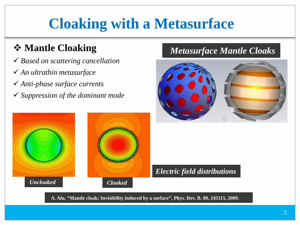
Cloaking with a Metasurface
3
Uncloaked Cloaked
Electric field distributions
A. Alu, “Mantle cloak: Invisibility induced by a surface”, Phys. Rev. B. 80, 245115, 2009.
Metasurface Mantle Cloaks Mantle Cloaking Based on scattering cancellation An ultrathin metasurface Anti-phase surface currents Suppression of the dominant mode
4
D
w
E
rε
g
D E
PEC
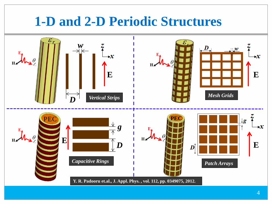
1-D and 2-D Periodic Structures
Vertical Strips
Capacitive Rings
E
Mesh Grids
Patch Arrays
PEC
E
rε
Y. R. Padooru et.al., J. Appl. Phys. , vol. 112, pp. 0349075, 2012.
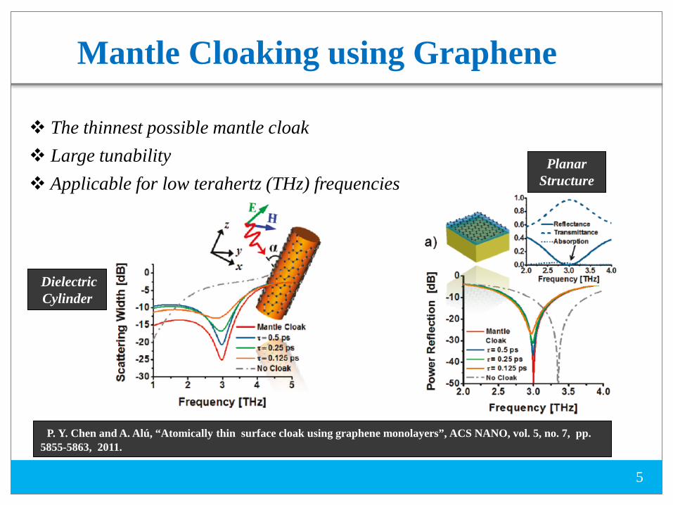
Mantle Cloaking using Graphene
5
The thinnest possible mantle cloak Large tunability Applicable for low terahertz (THz) frequencies
P. Y. Chen and A. Alú, “Atomically thin surface cloak using graphene monolayers”, ACS NANO, vol. 5, no. 7, pp. 5855-5863, 2011.
Dielectric Cylinder
Planar Structure

Graphene Nanopatches
6
Graphene monolayer provides inductive surface impedance A conducting object needs capacitive surface impedance to be cloaked To resolve this issue, a patterned graphene metasurface is proposed, which owns dual capacitive/inductive inductance and can be used to cloak both dielectric and conducting objects
PEC rε
Y. R. Padooru et.al., “Dual capacitive-inductive nature of periodic graphene patches: Transmission characteristics at low-terahertz frequencies”, Phys. Rev. B, vol. 87, pp. 115401, 2013.
: surface resistance per unit cell
: surface reactance per unit cell
: periodicity size
: gap size
: relative permittivity of the dielectric cylinder or the spacer

Cloaking using Graphene Nanopatches
7
Dielectric Cylinder PEC Cylinder
P. Y. Chen et. al, “Nanostructured graphene metasurface for tunable terahertz cloaking,” New. J. Phys., vol. 15, pp. 123029, 2013.

8
rεE
H θ
E
H θ
PEC E
H θ
PEC
cε
rε
Elliptical Cloak Designs at Microwaves
E
H θ
rε
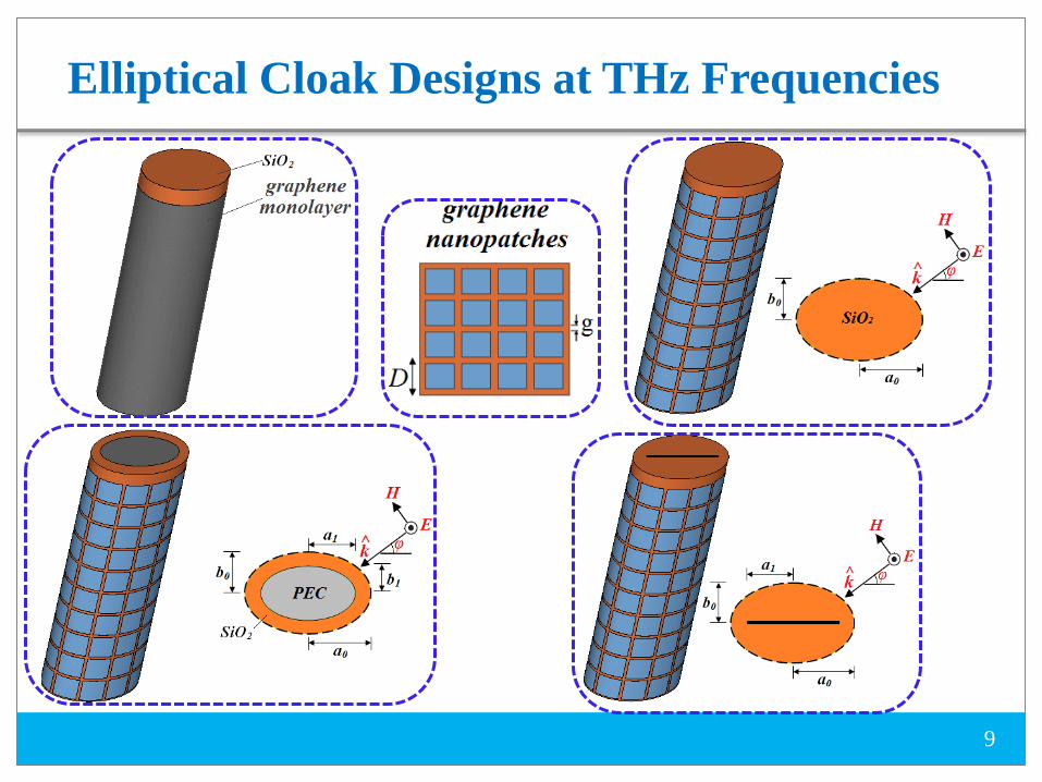
Elliptical Cloak Designs at THz Frequencies
9

10
Scattering from Strips by Mathieu Functions

Elliptical Coordinate System
11
: represents an ellipse
: represents a hyperbola
Scale factors
Focus

Mathieu Equation
12
Two-dimentional Helmholtz Equation: where: Using the method of separation of variables we have:
Radial Mathieu Equation
Angular Mathieu Equation
The radial Mathieu equation has four kinds of solution as: The angular Mathieu equation has the solution as:
p, m can be even or odd

Formulation of the Scattering Problem
13
Incident Electric Field
Scattered Electric Field
Transmitted Magnetic Field
Incident Magnetic Field
Scattered Magnetic Field
Transmitted Electric Field

Boundary Conditions
14
By applying boundary conditions :
Sheet Impedance Boundary Condition
Sheet Impedance Boundary Condition

Matrix Equation for Coefficients
15
Now, we apply the orthogonality property of angular Mathieu function as below:
If :
Matrix Equation for Coefficients
16
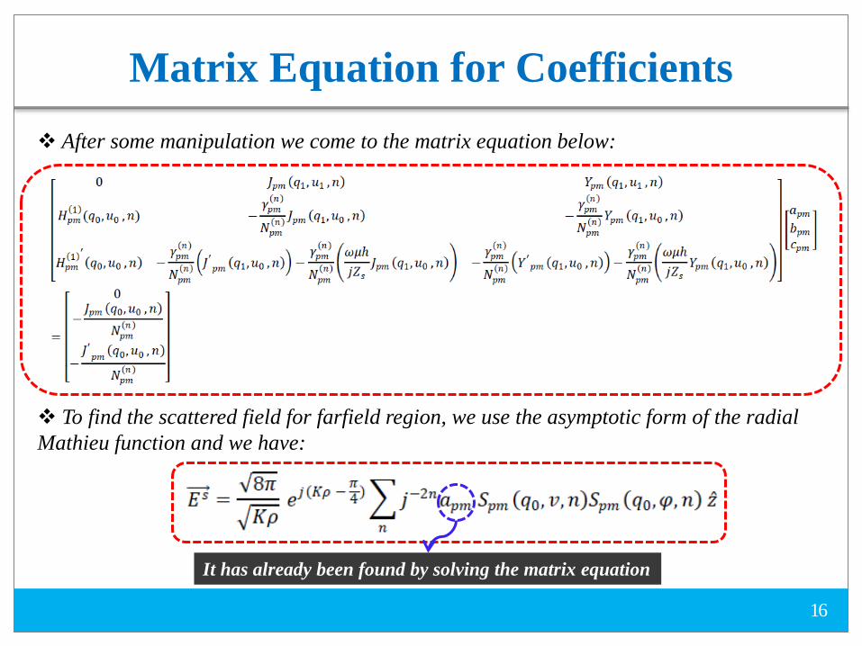
After some manipulation we come to the matrix equation below:
To find the scattered field for farfield region, we use the asymptotic form of the radial Mathieu function and we have:
It has already been found by solving the matrix equation

Bistatic Scattering Width
17
The two-dimensional bistatic cross section is defined as:
Finally, we have:

Optimum Reactance in terms of Observation Angle
18
To find the optimum reactance versus observation angle, we solve the matrix equation for the dominant scattering mode and require
Finally the optimum required reactance versus observation angle can be found as:
With the same approach we can find the optimum required reactance versus observation angle for the dielectric elliptical cylinder as:
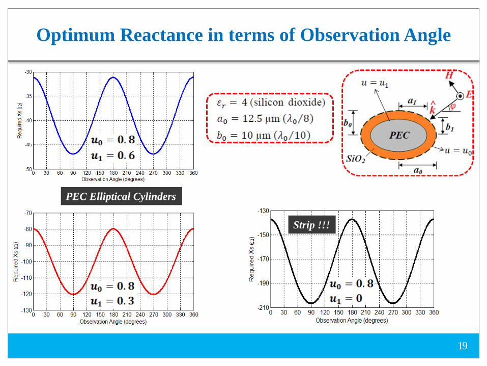
Optimum Reactance in terms of Observation Angle
19
PEC Elliptical Cylinders
Strip !!!
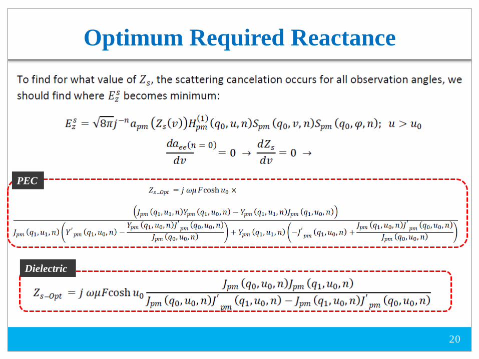
Optimum Required Reactance
20
PEC
Dielectric

Quasi-static Closed-form Condition
21
In the quasi-static limit( ), the closed-form condition for a PEC elliptical cylinder under TM-polarized illumination can be derived as:
And also, the closed-form condition for a dielectric elliptical cylinder under TM-polarized illumination can be derived as:

Surface Reactance Frequency Dispersion
22
Frequency dispersion of the surface reactance for graphene monolayer and nanopatches with respect to the optimum required is found as:
Required Reactance for Dielectric Ellipse
Required Reactance for PEC Ellipse
Required Reactance for Strip

Surface Conductivity of Graphene
23
G. W. Hanson, “Dyadic Green’s functions and guided surface waves for a surface conductivity model of graphene”, J. Appl. Phys., vol. 103, pp. 064302, 2008.
: charge of electron : temperature : energy : angular frequency : reduced Planck’s constant : chemical potential : momentum relaxation time
Intraband Contributions
Interband Contributions
Kubo Formula
σ1=sZ

Dielectric Elliptical Cylinder at THz Frequencies
24
Geometry parameters are:
The required reactance is found to be:
The design parameters are:

25
Power Flow and Far-field Pattern Uncloaked Cloaked
f= 3 THz

26
Uncloaked
Cloaked
Electric Field Distribution
f= 3 THz
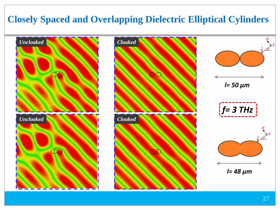
Closely Spaced and Overlapping Dielectric Elliptical Cylinders
27
Uncloaked
Uncloaked
Cloaked
Cloaked
l= 50 µm
l= 48 µm
f= 3 THz
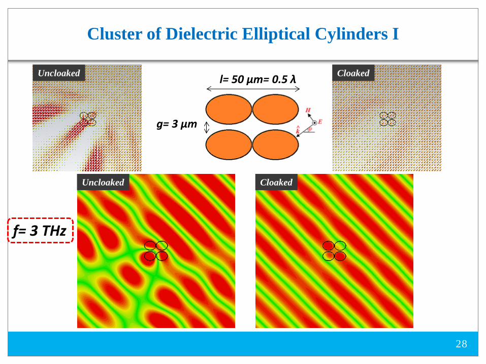
Cluster of Dielectric Elliptical Cylinders I
28
Uncloaked Cloaked
Uncloaked Cloaked
g= 3 µm
f= 3 THz
l= 50 µm= 0.5 λ

Cluster of Dielectric Elliptical Cylinders II
29
Cloaked Uncloaked
Uncloaked Cloaked
f= 3 THz
g= 3 µm
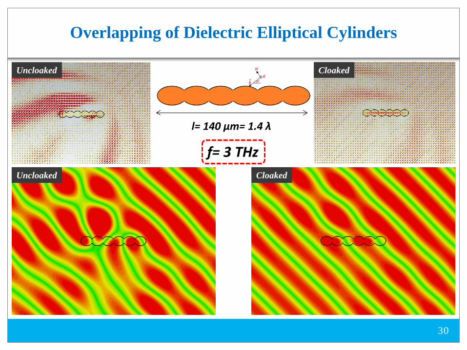
Overlapping of Dielectric Elliptical Cylinders
30
Cloaked Uncloaked
Uncloaked Cloaked
f= 3 THz
l= 140 µm= 1.4 λ

Dielectric Elliptical Cylinder at Microwave Frequencies
31
Geometry parameters are:
The required reactance is found to be:
The design parameters are:
rεN= 8
E
H θ

Dielectric Elliptical Cylinder at Microwave Frequencies
32
Geometry parameters are:
The required reactance is found to be: The design parameters are:
E
H θ
rε
N= 8
N= 3
N= 3 N= 8

33
Electric Field Distribution
Uncloaked
Cloaked
f= 3 GHz
rε
N= 8

34
Geometry parameters are:
The required reactance is found to be:
The design parameters are:
Dielectric Elliptical Cylinder at THz Frequencies

PEC Elliptical Cylinder at THz Frequencies
35
Geometry parameters are:
The required reactance is found to be:
The design parameters are:
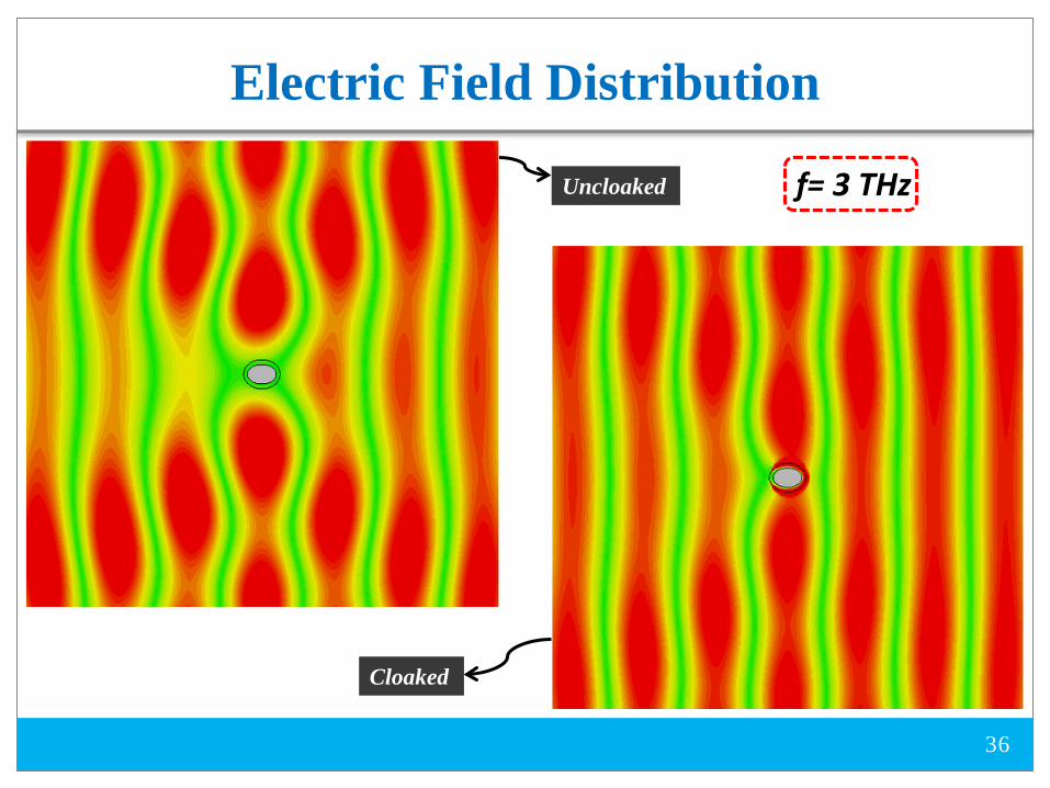
36
Uncloaked
Cloaked
Electric Field Distribution
f= 3 THz

PEC Elliptical Cylinder at Microwave Frequencies
37
Geometry parameters are:
The required reactance is found to be:
The design parameters are:
E
H θPEC

2-D Metasurface Cloak for PEC at Microwaves
38
Geometry parameters are:
The required reactance is found to be:
The design parameters are:
E
H θ
PEC
N= 10
cε

39
Power Flow and Far-field Pattern Uncloaked Cloaked
f= 3 GHz
N= 10
cε

40
Uncloaked
Cloaked
Electric Field Distribution
PEC cε
f= 3 GHz

Strip (Degenerated Ellipse)
41
A strip can be modeled as a degenerated ellipse
Geometry parameters are:

42
Power Flow and Far-field Pattern Cloaked Uncloaked
f= 3 THz
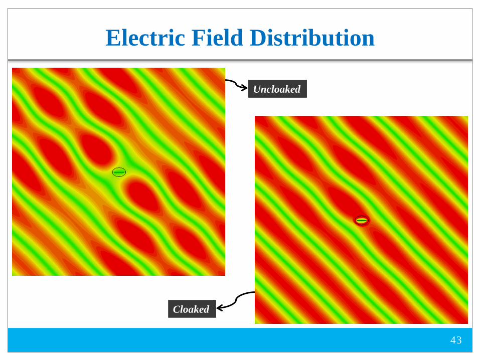
43
Uncloaked
Cloaked
Electric Field Distribution

Cloaking for Two Strips
44
Uncloaked Cloaked
f= 3 THz

Two Strips Horizontally Oriented
45
Uncloaked Cloaked
f= 3 THz

Two Strips with Overlapping Cloaks
46
Uncloaked Cloaked
Uncloaked Cloaked
f= 3 THz
g= 3.7 µm
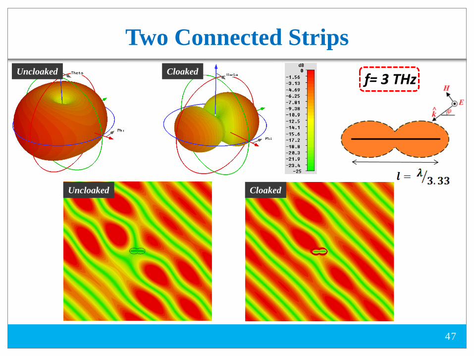
Two Connected Strips
47
Cloaked Uncloaked
Uncloaked Cloaked
f= 3 THz

Wire Dipole Antennas
48

Strip Dipole Antennas
49
Here, we present the applicability of elliptically shaped metasurfaces in order to reduce the mutual coupling between two closely spaced antennas. First, we consider two strip dipole antennas resonating at f= 1 GHz and f= 5 GHz, which are separated by a short distance of d= λ/10 (at f= 5 GHz). (Case I)
Second, we consider two strip dipole antennas resonating at f= 3.02 GHz and f= 3.33 GHz, which are separated by a short distance of d= λ/10 (at f= 3 GHz). (Case II)
To present how the mutual blockage is overcome, we consider three different scenarios of isolated, uncloaked, and cloaked for each case.

Case I
50
We consider Antenna I (isolated) and Antenna II (isolated) which resonate at f= 1 GHz and f= 5 GHz, respectively, with omni-directional radiation patterns as shown below. Each antenna is matched to a 75-Ω feed.
Antenna I Antenna II
W= 4 mm
L= 130.5.5 mm
Δ= 0.2 mm W= 4 mm
L= 27.5 mm
Δ= 0.2 mm
Neighboring Uncloaked Dipole Antennas
51
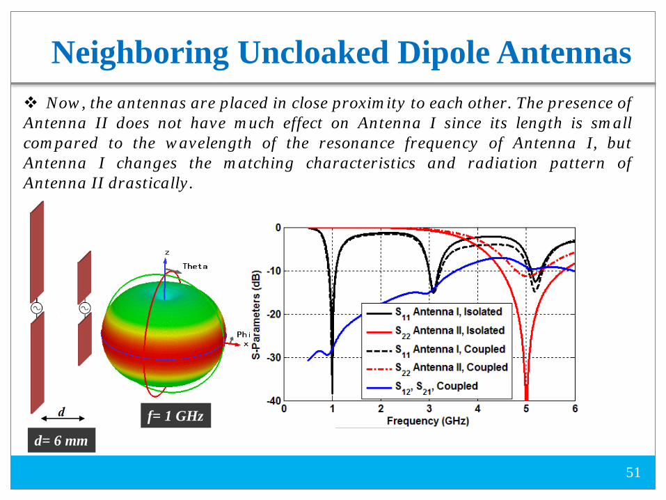
Now, the antennas are placed in close proximity to each other. The presence of Antenna II does not have much effect on Antenna I since its length is small compared to the wavelength of the resonance frequency of Antenna I, but Antenna I changes the matching characteristics and radiation pattern of Antenna II drastically.
f= 1 GHz f= 5 GHz
d= 6 mm

Cloaking 2-D Metallic Strip
52
a 2-D Metallic Strip can be considered as a degenerated ellipse
TM-polarized plane-wave excitation.

Cloaking 2-D Metallic Strip
53
Uncloaked Cloaked
How to Cloak Antenna I?
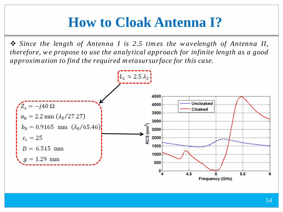
54
Since the length of Antenna I is 2.5 times the wavelength of Antenna II, therefore, we propose to use the analytical approach for infinite length as a good approximation to find the required metasursurface for this case.

55
3-D radiation patterns of Antenna I at 1 GHz (left) and Antenna II at 5 GHz (right) for the scenario, in which Antenna I is cloaked for the resonance frequency of Antenna II and the antennas are in close proximity.
Antenna I
Antenna II
Neighboring Cloaked Dipole Antennas
f= 1 GHz
f= 5 GHz

56
Restoration of gain patterns at the first and second resonance frequency of Antenna I (1 GHz, 3 GHz) and resonance frequency of Antenna II
2-D Gain Pattern
E-plane H-plane
Antenna I
Antenna I
H-plane E-plane
E-plane H-plane
Antenna I
f= 1 GHz f= 3 GHz
f= 5 GHz

Isolated Antenna I (Case II)
57
W= 4 mm f= 3.02 GHz
L
L= 45.8 mm
Δ
Δ= 0.2 mm
First of all, we consider the antenna I (Isolated Case), which resonates at f= 3.02 GHz with an omni-directional radiation pattern as shown below. The S11 of the antenna along with its dimensions are shown below. The antenna is matched to a 75-Ω feed.

Isolated Antenna II (Case II)
58
f= 3.33 GHz W= 4 mm L= 41.5 mm Δ= 0.2 mm
Then, we consider the antenna II (Isolated Case), which resonates at f= 3.33 GHz with an omni-directional radiation pattern as illustrated below. The S11 of the antenna along with its dimensions are shown below. The antenna is matched to a 75-Ω feed.
L Δ
Neighboring Uncloaked Dipole Antennas
59
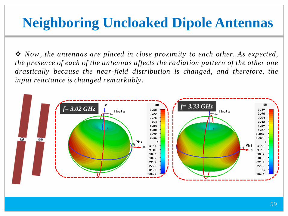
Now, the antennas are placed in close proximity to each other. As expected, the presence of each of the antennas affects the radiation pattern of the other one drastically because the near-field distribution is changed, and therefore, the input reactance is changed remarkably.
f= 3.02 GHz f= 3.33 GHz

60
To reduce the mutual coupling, we cover each dipole antenna with an elliptically shaped mantle cloak structure consisting of inductive vertical strips and a spacer between the strip and the metasurface. The presence of the spacer, and then, the cloak structure, changes the resonance frequency of the antenna. Therefore, we reduce the length of the antenna in order to provide good matching at the desired working frequency. On the other hand, the parameters of the cloak structure should be chosen in a way that each antenna is invisible at the resonance frequency of the other one.
We have performed an appropriate optimization to minimize the 3-D total RCS of each dipole antenna under Transverse Magnetic (TM) plane-wave excitation.
Separated Cloaked Dipole Antennas
61
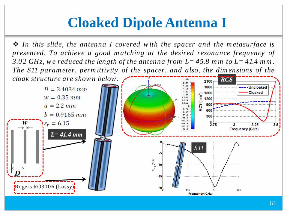
In this slide, the antenna I covered with the spacer and the metasurface is presented. To achieve a good matching at the desired resonance frequency of 3.02 GHz, we reduced the length of the antenna from L= 45.8 mm to L= 41.4 mm. The S11 parameter, permittivity of the spacer, and also, the dimensions of the cloak structure are shown below.
Cloaked Dipole Antenna I
Rogers RO3006 (Lossy)
L= 41.4 mm
S11
RCS

62
In this slide, the antenna II covered with the spacer and the cloak design is presented. To achieve a good matching at the desired resonance frequency of 3.02 GHz, again, we reduced the length of the antenna from L= 41.5 mm to L= 38.8 mm. The S11 parameter, permittivity of the spacer, and also, the dimensions of the cloak structure are shown below.
Cloaked Dipole Antenna II
Rogers TMM 10i (Lossy)
L= 38.8 mm
RCS

63
The reflection coefficients at the input port of the Antenna I and the Antenna II in the cloaked case (the antennas are in close proximity to each other) are shown here. As can be seen, the impedance matching of the antennas are good near the resonant frequency of each isolated strip dipole antenna.
Neighboring Cloaked Dipole Antennas
Radiation patterns are:

Neighboring Cloaked Dipole Antennas
64
f= 2.9441 GHz
f= 3.3515 GHz
E-Plane H-Plane
f= 2.9441 GHz
f= 3.3515 GHz
Conclusions
65
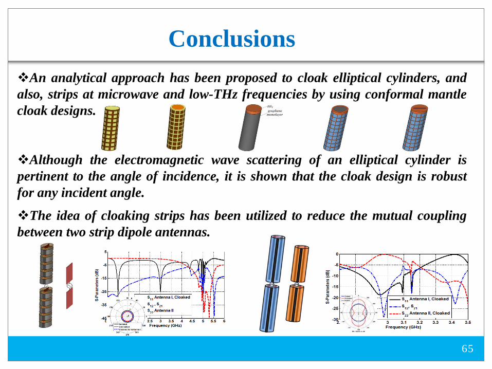
An analytical approach has been proposed to cloak elliptical cylinders, and also, strips at microwave and low-THz frequencies by using conformal mantle cloak designs.
Although the electromagnetic wave scattering of an elliptical cylinder is pertinent to the angle of incidence, it is shown that the cloak design is robust for any incident angle.
The idea of cloaking strips has been utilized to reduce the mutual coupling between two strip dipole antennas.