Reduction of Gear Pair Transmission Error with Tooth Profile...
12
Reduction of Gear Pair Transmission Error with Tooth Profile Modification R. Tharmakulasingam, Dr. G. Alfano, Dr. M Atherton Brunel University, School of Engineering and Design Uxbridge, Middlesex, UB8 3PH, United Kingdom Email: [email protected] Abstract The gear noise problem that widely occurs in power transmission systems is typically characterised by one or more high amplitude acoustic signals. The noise originates from the vibration of the gear pair system caused by transmission error excitation that arises from tooth profile errors, misalignment and tooth deflections. This paper aims to further research the effect of tooth profile modifications on the transmission error of gear pairs. A spur gear pair was modelled using finite elements, and the gear mesh was simulated and analysed under static conditions. The results obtained were used to study the effect of intentional tooth profile modifications on the transmission error of the gear pair. A detailed parametric study, involving development of an optimisation algorithm to design the tooth modifications, was performed to quantify the changes in the transmission error as a function of tooth profile modification parameters as compared to an unmodified gear pair baseline. 1 Introduction Over the past 40 years, a lot of research has been conducted in relation to the dynamics of gears and the resulting noise generated [1-3]. During this period, the hypothesis that transmission error (TE) was the main cause of most of the noise emitted by gear pairs was developed and established [4-5]. In recent years, many attempts have been made by numerous authors to set up models aimed at simulating the dynamic behaviour of gears [6-7]. The mathematical formulations range from single-degree-of freedom (SDOF) models to finite element models (2D & 3D), but virtually all gear dynamic models consider that transmission error (TE) and variations in mesh stiffness are the primary sources of excitation. From the gear designer’s point of view, the definition of tooth modifications for low-noise gears also relies on the minimization of transmission error variations [8-10]. A vast number of mathematical models used in gear dynamics have been reviewed and classified by Ozguven and Houser [11]. The sources of mesh excitation and its contribution to system excitation and particularly to gear noise have been discussed by Houser [12]. Wang et al [13] have undertaken a comprehensive and critical review of the models developed and methods used to solve the non-linear dynamics of geared systems and addressed the issues of further research on the non-linear vibration in gear transmission systems. Several research groups have developed generic models of single-stage gearboxes to include gears, shafts, bearings, and the housing in order to compute the transmission of dynamic bearing forces attributable to the excitation of the static TE and the resulting dynamic response of the gearbox housing. Using these techniques, it has been shown possible to optimize static TE characteristics for a range of torques by introducing appropriate tooth modifications and micro-geometries to minimize static TE variations. Even though contact mechanics and finite-element analysis (FEA) simulation provide valuable tools that are used to investigate gear dynamics, there is still a need for more experimental investigation in order to
Transcript of Reduction of Gear Pair Transmission Error with Tooth Profile...
Reduction of Gear Pair Transmission Error with Tooth Profile Modification
R. Tharmakulasingam, Dr. G. Alfano, Dr. M Atherton Brunel University, School of Engineering and Design Uxbridge, Middlesex, UB8 3PH, United Kingdom Email: [email protected]
Abstract The gear noise problem that widely occurs in power transmission systems is typically characterised by one or more high amplitude acoustic signals. The noise originates from the vibration of the gear pair system caused by transmission error excitation that arises from tooth profile errors, misalignment and tooth deflections. This paper aims to further research the effect of tooth profile modifications on the transmission error of gear pairs. A spur gear pair was modelled using finite elements, and the gear mesh was simulated and analysed under static conditions. The results obtained were used to study the effect of intentional tooth profile modifications on the transmission error of the gear pair. A detailed parametric study, involving development of an optimisation algorithm to design the tooth modifications, was performed to quantify the changes in the transmission error as a function of tooth profile modification parameters as compared to an unmodified gear pair baseline.
1 Introduction
Over the past 40 years, a lot of research has been conducted in relation to the dynamics of gears and the resulting noise generated [1-3]. During this period, the hypothesis that transmission error (TE) was the main cause of most of the noise emitted by gear pairs was developed and established [4-5]. In recent years, many attempts have been made by numerous authors to set up models aimed at simulating the dynamic behaviour of gears [6-7]. The mathematical formulations range from single-degree-of freedom (SDOF) models to finite element models (2D & 3D), but virtually all gear dynamic models consider that transmission error (TE) and variations in mesh stiffness are the primary sources of excitation. From the gear designer’s point of view, the definition of tooth modifications for low-noise gears also relies on the minimization of transmission error variations [8-10]. A vast number of mathematical models used in gear dynamics have been reviewed and classified by Ozguven and Houser [11]. The sources of mesh excitation and its contribution to system excitation and particularly to gear noise have been discussed by Houser [12].
Wang et al [13] have undertaken a comprehensive and critical review of the models developed and methods used to solve the non-linear dynamics of geared systems and addressed the issues of further research on the non-linear vibration in gear transmission systems. Several research groups have developed generic models of single-stage gearboxes to include gears, shafts, bearings, and the housing in order to compute the transmission of dynamic bearing forces attributable to the excitation of the static TE and the resulting dynamic response of the gearbox housing. Using these techniques, it has been shown possible to optimize static TE characteristics for a range of torques by introducing appropriate tooth modifications and micro-geometries to minimize static TE variations.
Even though contact mechanics and finite-element analysis (FEA) simulation provide valuable tools that are used to investigate gear dynamics, there is still a need for more experimental investigation in order to
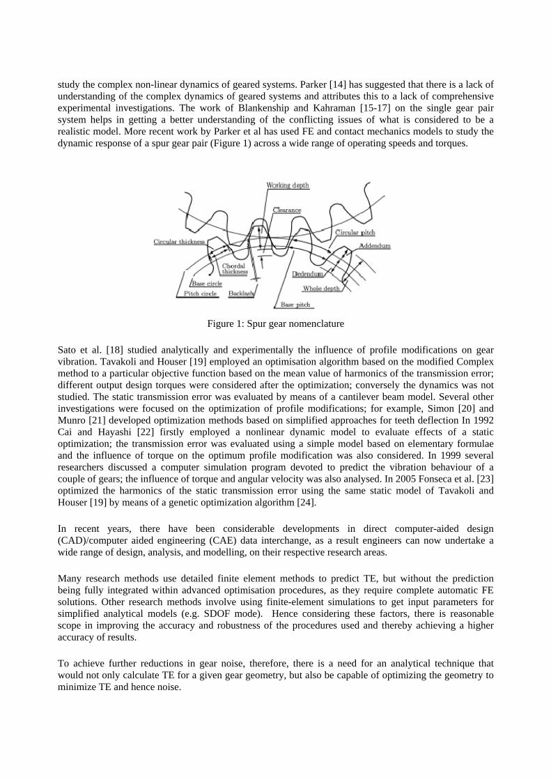
study the complex non-linear dynamics of geared systems. Parker [14] has suggested that there is a lack of understanding of the complex dynamics of geared systems and attributes this to a lack of comprehensive experimental investigations. The work of Blankenship and Kahraman [15-17] on the single gear pair system helps in getting a better understanding of the conflicting issues of what is considered to be a realistic model. More recent work by Parker et al has used FE and contact mechanics models to study the dynamic response of a spur gear pair (Figure 1) across a wide range of operating speeds and torques.
Figure 1: Spur gear nomenclature
Sato et al. [18] studied analytically and experimentally the influence of profile modifications on gear vibration. Tavakoli and Houser [19] employed an optimisation algorithm based on the modified Complex method to a particular objective function based on the mean value of harmonics of the transmission error; different output design torques were considered after the optimization; conversely the dynamics was not studied. The static transmission error was evaluated by means of a cantilever beam model. Several other investigations were focused on the optimization of profile modifications; for example, Simon [20] and Munro [21] developed optimization methods based on simplified approaches for teeth deflection In 1992 Cai and Hayashi [22] firstly employed a nonlinear dynamic model to evaluate effects of a static optimization; the transmission error was evaluated using a simple model based on elementary formulae and the influence of torque on the optimum profile modification was also considered. In 1999 several researchers discussed a computer simulation program devoted to predict the vibration behaviour of a couple of gears; the influence of torque and angular velocity was also analysed. In 2005 Fonseca et al. [23] optimized the harmonics of the static transmission error using the same static model of Tavakoli and Houser [19] by means of a genetic optimization algorithm [24].
In recent years, there have been considerable developments in direct computer-aided design (CAD)/computer aided engineering (CAE) data interchange, as a result engineers can now undertake a wide range of design, analysis, and modelling, on their respective research areas.
Many research methods use detailed finite element methods to predict TE, but without the prediction being fully integrated within advanced optimisation procedures, as they require complete automatic FE solutions. Other research methods involve using finite-element simulations to get input parameters for simplified analytical models (e.g. SDOF mode). Hence considering these factors, there is reasonable scope in improving the accuracy and robustness of the procedures used and thereby achieving a higher accuracy of results.
To achieve further reductions in gear noise, therefore, there is a need for an analytical technique that would not only calculate TE for a given gear geometry, but also be capable of optimizing the geometry to minimize TE and hence noise.
2 Gear noise
2.1 Transmission Error
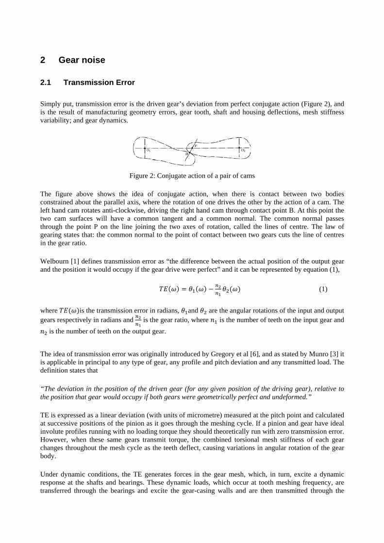
Simply put, transmission error is the driven gear’s deviation from perfect conjugate action (Figure 2), and is the result of manufacturing geometry errors, gear tooth, shaft and housing deflections, mesh stiffness variability; and gear dynamics.
Figure 2: Conjugate action of a pair of cams
The figure above shows the idea of conjugate action, when there is contact between two bodies constrained about the parallel axis, where the rotation of one drives the other by the action of a cam. The left hand cam rotates anti-clockwise, driving the right hand cam through contact point B. At this point the two cam surfaces will have a common tangent and a common normal. The common normal passes through the point P on the line joining the two axes of rotation, called the lines of centre. The law of gearing states that: the common normal to the point of contact between two gears cuts the line of centres in the gear ratio.
Welbourn [1] defines transmission error as “the difference between the actual position of the output gear and the position it would occupy if the gear drive were perfect” and it can be represented by equation (1),
(1)
where is the transmission error in radians, and are the angular rotations of the input and output gears respectively in radians and is the gear ratio, where is the number of teeth on the input gear and is the number of teeth on the output gear.
The idea of transmission error was originally introduced by Gregory et al [6], and as stated by Munro [3] it is applicable in principal to any type of gear, any profile and pitch deviation and any transmitted load. The definition states that
“The deviation in the position of the driven gear (for any given position of the driving gear), relative to the position that gear would occupy if both gears were geometrically perfect and undeformed.”
TE is expressed as a linear deviation (with units of micrometre) measured at the pitch point and calculated at successive positions of the pinion as it goes through the meshing cycle. If a pinion and gear have ideal involute profiles running with no loading torque they should theoretically run with zero transmission error. However, when these same gears transmit torque, the combined torsional mesh stiffness of each gear changes throughout the mesh cycle as the teeth deflect, causing variations in angular rotation of the gear body.
Under dynamic conditions, the TE generates forces in the gear mesh, which, in turn, excite a dynamic response at the shafts and bearings. These dynamic loads, which occur at tooth meshing frequency, are transferred through the bearings and excite the gear-casing walls and are then transmitted through the
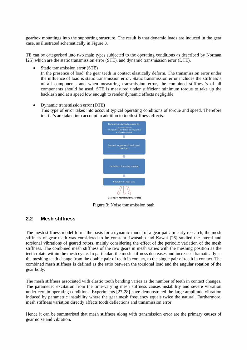
gearbox mountings into the supporting structure. The result is that dynamic loads are induced in the gear case, as illustrated schematically in Figure 3.
TE can be categorised into two main types subjected to the operating conditions as described by Norman [25] which are the static transmission error (STE), and dynamic transmission error (DTE).
• Static transmission error (STE) In the presence of load, the gear teeth in contact elastically deform. The transmission error under the influence of load is static transmission error. Static transmission error includes the stiffness’s of all components and when measuring transmission error, the combined stiffness’s of all components should be used. STE is measured under sufficient minimum torque to take up the backlash and at a speed low enough to render dynamic effects negligible
• Dynamic transmission error (DTE) This type of error takes into account typical operating conditions of torque and speed. Therefore inertia’s are taken into account in addition to tooth stiffness effects.
Figure 3: Noise transmission path
2.2 Mesh stiffness
The mesh stiffness model forms the basis for a dynamic model of a gear pair. In early research, the mesh stiffness of gear teeth was considered to be constant. Iwatsubo and Kawai [26] studied the lateral and torsional vibrations of geared rotors, mainly considering the effect of the periodic variation of the mesh stiffness. The combined mesh stiffness of the two gears in mesh varies with the meshing position as the teeth rotate within the mesh cycle. In particular, the mesh stiffness decreases and increases dramatically as the meshing teeth change from the double pair of teeth in contact, to the single pair of teeth in contact. The combined mesh stiffness is defined as the ratio between the torsional load and the angular rotation of the gear body.
The mesh stiffness associated with elastic tooth bending varies as the number of teeth in contact changes. The parametric excitation from the time-varying mesh stiffness causes instability and severe vibration under certain operating conditions. Experiments [27-28] have demonstrated the large amplitude vibration induced by parametric instability where the gear mesh frequency equals twice the natural. Furthermore, mesh stiffness variation directly affects tooth deflections and transmission error.
Hence it can be summarised that mesh stiffness along with transmission error are the primary causes of gear noise and vibration.

3 Gear geometry
3.1 Gear profile
Gear designers are faced with having to compute accurate mathematical models of gears, and most three dimensional solid modelling programs cannot easily accommodate the true involute geometry used to generate the tooth profile, other than by approximating to a small number of finite points. As a result, existing methods for gear generating involve the following procedures:
• Establish the mathematical model of the gear drives according to the manufacturing process and gear meshing theory
• Export the calculated surface data points into a CAD package, construct the surface data points into the gear surface, and trim the surface according to the design parameters, that is, gear geometry generation solely from a CAD tool owing to the geometry generation limitations of the currently available commercial FEA software
The geometry importation tools may cause many problems, mainly due to the disparity between standard interpretation and level implementation. Analysts should pay special attention to the accuracy of modelling after the models have been imported and thereafter to obtained gear geometry clear-up. Thus, designing gears using this methodology is inherently restrictive because of the resulting inaccuracies. The present work will generate the required geometry within the FEA software [29] instead of importing from other CAD packages, using the Python programming language, mathematically, to generate the gear tooth profile on the basis of the involute curve (Figure 4).
Figure 4: Generation of an involute curve
This method is highly accurate geometrically, and may be the best way to obtain highly accurate gear geometry in order to avoid the disparity between standard interpretation and level implementation. This accurate gear generation method provides researchers with a powerful tool for investigating the effects of gear tooth surface micro-geometry modifications
3.2 Profile modification
The two main methods currently being implemented, in order to reduce the gear noise and vibration response of the system are by means of macro-geometry and micro-geometry modifications.
Macro-geometry is defined by gear parameters such as: number of teeth, diameters, pressure angle, backlash and clearance. Many authors studied the effect of the involute contact ratio on both spur and helical gear vibrations [17-18]. Macro-geometric modifications involve an important and expensive change of the gear pair as well as the other members of the gear train; they are feasible only at the first steps of the design process. High quality surface finishing and strict tolerances can lead to excessive manufacturing costs; moreover, their effect on vibrations can be disappointingly small.
Micro-geometric modifications include the intentional removal of material from the gear teeth flanks, so that the resulting shape is no longer a perfect involute; such modifications compensate teeth deflections under load, so that the resulting transmission error is minimized for a specific torque [2]. Therefore in this study, the micro-geometry modifications will be the focus of the analysis.
3.3 Finite element model
A spur gear pair was initially modelled using finite elements (FE) software [29], and the gear mesh was simulated and analysed under static conditions. In order to run the static analysis, several assumptions have to be made:
• Plain strain conditions: Due to the spur gear geometry. 2D plane strain analysis is adequate for an involute spur gear tooth. Moreover the 2-D version of the software requires little time both for model definition and simulations, with a high precision of the results.
• Frictionless contact: In order to remove uncertainty of the Coulomb friction coefficient, the friction force is assumed not to affect the TE shape function substantially.
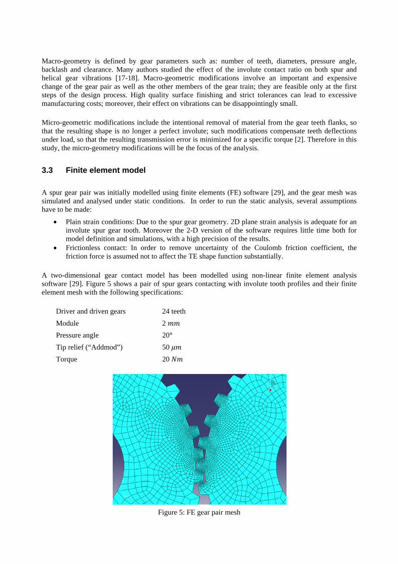
A two-dimensional gear contact model has been modelled using non-linear finite element analysis software [29]. Figure 5 shows a pair of spur gears contacting with involute tooth profiles and their finite element mesh with the following specifications:
Driver and driven gears 24 teeth Module 2 Pressure angle 20 Tip relief (“Addmod”) 50 Torque 20
Figure 5: FE gear pair mesh
This analysis is run once for a given macro-geometry which requires essential input details such as number of teeth, module, tooth depth, addendum and dedendum radii, modifications and pitch circle diameter etc. The preprocessor in the FEA software automatically generates the FE model of the two gears, and an internal FE solver generates the compliance and stress coefficients.
The second part of the procedure involves a tooth contact analysis (TCA), which is run repeatedly to optimize the micro-geometry modification in order to achieve minimum TE and gear stress. This requires input details relevant to the modification being made, such as root relief, profile crowning, lead correction, end relief, face crowning, or any defined surface topography, in the case of this study it is tip relief. As this part of the method requires very little computational time, the calculations can be repeated with varying geometry to achieve minimum TE and stress. The output from the calculation procedure yields the STE, tooth load, and contact and bending stress as a distribution across the face width at a particular phase mesh between the gears.
3.4 Profile modification algorithm
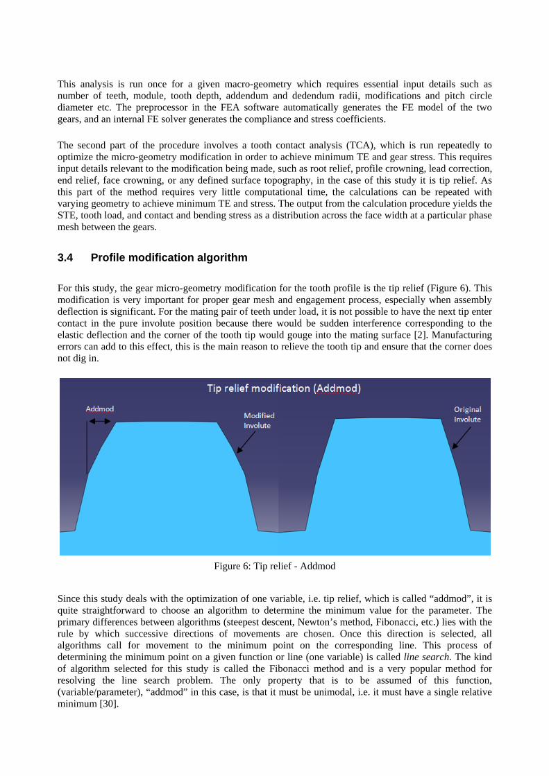
For this study, the gear micro-geometry modification for the tooth profile is the tip relief (Figure 6). This modification is very important for proper gear mesh and engagement process, especially when assembly deflection is significant. For the mating pair of teeth under load, it is not possible to have the next tip enter contact in the pure involute position because there would be sudden interference corresponding to the elastic deflection and the corner of the tooth tip would gouge into the mating surface [2]. Manufacturing errors can add to this effect, this is the main reason to relieve the tooth tip and ensure that the corner does not dig in.
Figure 6: Tip relief - Addmod
Since this study deals with the optimization of one variable, i.e. tip relief, which is called “addmod”, it is quite straightforward to choose an algorithm to determine the minimum value for the parameter. The primary differences between algorithms (steepest descent, Newton’s method, Fibonacci, etc.) lies with the rule by which successive directions of movements are chosen. Once this direction is selected, all algorithms call for movement to the minimum point on the corresponding line. This process of determining the minimum point on a given function or line (one variable) is called line search. The kind of algorithm selected for this study is called the Fibonacci method and is a very popular method for resolving the line search problem. The only property that is to be assumed of this function, (variable/parameter), “addmod” in this case, is that it must be unimodal, i.e. it must have a single relative minimum [30].
4 Results and discussion
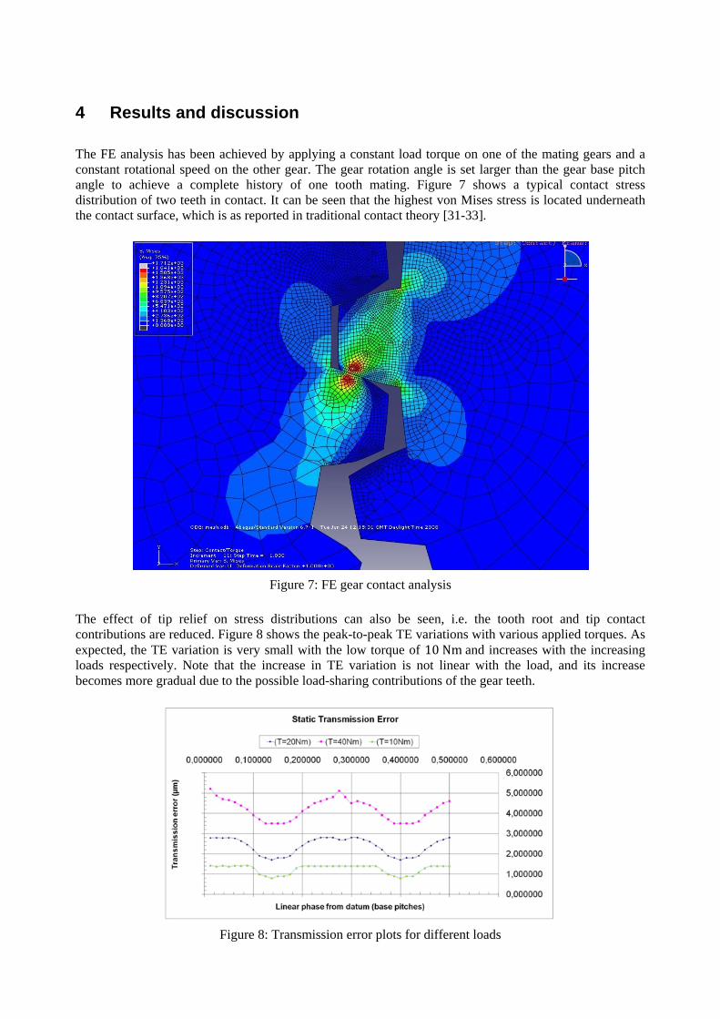
The FE analysis has been achieved by applying a constant load torque on one of the mating gears and a constant rotational speed on the other gear. The gear rotation angle is set larger than the gear base pitch angle to achieve a complete history of one tooth mating. Figure 7 shows a typical contact stress distribution of two teeth in contact. It can be seen that the highest von Mises stress is located underneath the contact surface, which is as reported in traditional contact theory [31-33].
Figure 7: FE gear contact analysis
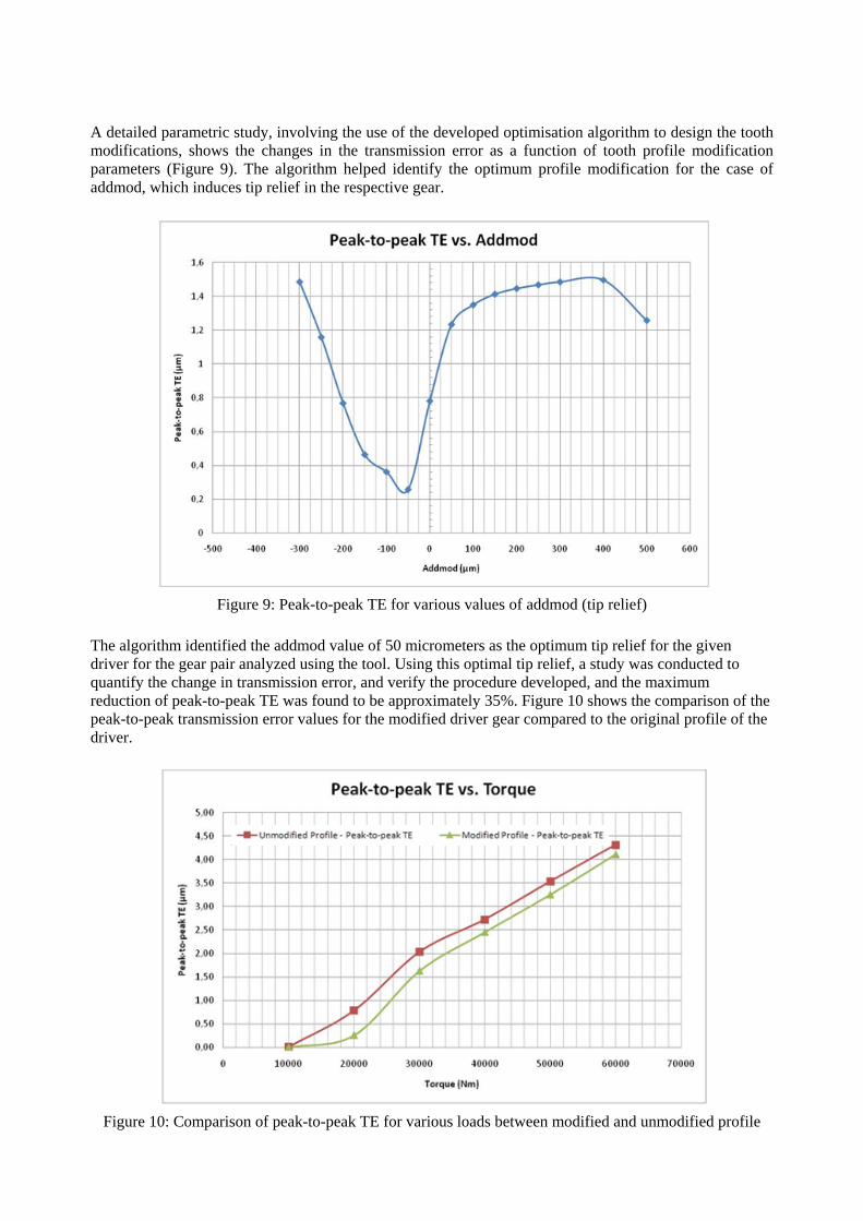
The effect of tip relief on stress distributions can also be seen, i.e. the tooth root and tip contact contributions are reduced. Figure 8 shows the peak-to-peak TE variations with various applied torques. As expected, the TE variation is very small with the low torque of 10 and increases with the increasing loads respectively. Note that the increase in TE variation is not linear with the load, and its increase becomes more gradual due to the possible load-sharing contributions of the gear teeth.
Nm
Figure 8: Transmission error plots for different loads
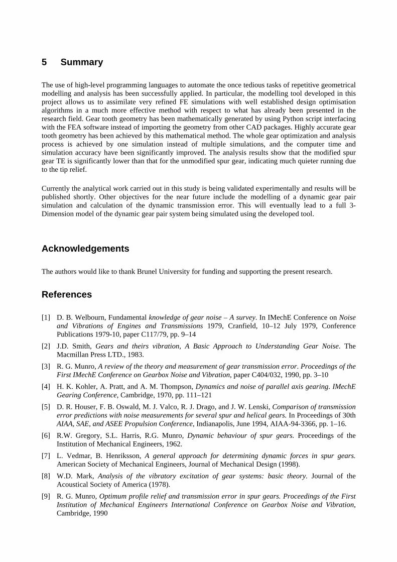
A detailed parametric study, involving the use of the developed optimisation algorithm to design the tooth modifications, shows the changes in the transmission error as a function of tooth profile modification parameters (Figure 9). The algorithm helped identify the optimum profile modification for the case of addmod, which induces tip relief in the respective gear.
Figure 9: Peak-to-peak TE for various values of addmod (tip relief)
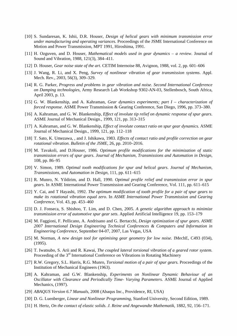
The algorithm identified the addmod value of 50 micrometers as the optimum tip relief for the given driver for the gear pair analyzed using the tool. Using this optimal tip relief, a study was conducted to quantify the change in transmission error, and verify the procedure developed, and the maximum reduction of peak-to-peak TE was found to be approximately 35%. Figure 10 shows the comparison of the peak-to-peak transmission error values for the modified driver gear compared to the original profile of the driver.
Figure 10: Comparison of peak-to-peak TE for various loads between modified and unmodified profile
5 Summary
The use of high-level programming languages to automate the once tedious tasks of repetitive geometrical modelling and analysis has been successfully applied. In particular, the modelling tool developed in this project allows us to assimilate very refined FE simulations with well established design optimisation algorithms in a much more effective method with respect to what has already been presented in the research field. Gear tooth geometry has been mathematically generated by using Python script interfacing with the FEA software instead of importing the geometry from other CAD packages. Highly accurate gear tooth geometry has been achieved by this mathematical method. The whole gear optimization and analysis process is achieved by one simulation instead of multiple simulations, and the computer time and simulation accuracy have been significantly improved. The analysis results show that the modified spur gear TE is significantly lower than that for the unmodified spur gear, indicating much quieter running due to the tip relief.
Currently the analytical work carried out in this study is being validated experimentally and results will be published shortly. Other objectives for the near future include the modelling of a dynamic gear pair simulation and calculation of the dynamic transmission error. This will eventually lead to a full 3-Dimension model of the dynamic gear pair system being simulated using the developed tool.
Acknowledgements
The authors would like to thank Brunel University for funding and supporting the present research.
References
[1] D. B. Welbourn, Fundamental knowledge of gear noise – A survey. In IMechE Conference on Noise and Vibrations of Engines and Transmissions 1979, Cranfield, 10–12 July 1979, Conference Publications 1979-10, paper C117/79, pp. 9–14
[2] J.D. Smith, Gears and theirs vibration, A Basic Approach to Understanding Gear Noise. The Macmillan Press LTD., 1983.
[3] R. G. Munro, A review of the theory and measurement of gear transmission error. Proceedings of the First IMechE Conference on Gearbox Noise and Vibration, paper C404/032, 1990, pp. 3–10
[4] H. K. Kohler, A. Pratt, and A. M. Thompson, Dynamics and noise of parallel axis gearing. IMechE Gearing Conference, Cambridge, 1970, pp. 111–121
[5] D. R. Houser, F. B. Oswald, M. J. Valco, R. J. Drago, and J. W. Lenski, Comparison of transmission error predictions with noise measurements for several spur and helical gears. In Proceedings of 30th AIAA, SAE, and ASEE Propulsion Conference, Indianapolis, June 1994, AIAA-94-3366, pp. 1–16.
[6] R.W. Gregory, S.L. Harris, R.G. Munro, Dynamic behaviour of spur gears. Proceedings of the Institution of Mechanical Engineers, 1962.
[7] L. Vedmar, B. Henriksson, A general approach for determining dynamic forces in spur gears. American Society of Mechanical Engineers, Journal of Mechanical Design (1998).
[8] W.D. Mark, Analysis of the vibratory excitation of gear systems: basic theory. Journal of the Acoustical Society of America (1978).
[9] R. G. Munro, Optimum profile relief and transmission error in spur gears. Proceedings of the First Institution of Mechanical Engineers International Conference on Gearbox Noise and Vibration, Cambridge, 1990
[10] S. Sundaresan, K. Ishii, D.R. Houser, Design of helical gears with minimum transmission error under manufacturing and operating variances. Proceedings of the JSME International Conference on Motion and Power Transmission, MPT 1991, Hiroshima, 1991.
[11] H. Ozguven, and D. Houser, Mathematical models used in gear dynamics – a review. Journal of Sound and Vibration, 1988, 121(3), 384–411.
[12] D. Houser, Gear noise state of the art. CETIM Internoise 88, Avignon, 1988, vol. 2, pp. 601–606 [13] J. Wang, R. Li, and X. Peng, Survey of nonlinear vibration of gear transmission systems. Appl.
Mech. Rev., 2003, 56(3), 309–329. [14] R. G. Parker, Progress and problems in gear vibration and noise. Second International Conference
on Damping technologies, Army Research Lab Workshop 9302-AN-03, Stellenbosch, South Africa, April 2003, p. 13.
[15] G. W. Blankenship, and A. Kahraman, Gear dynamics experiments; part I – characterization of forced response. ASME Power Transmission & Gearing Conference, San Diego, 1996, pp. 373–380.
[16] A. Kahraman, and G. W. Blankenship, Effect of involute tip relief on dynamic response of spur gears. ASME Journal of Mechanical Design., 1999, 121, pp. 313–315
[17] A. Kahraman, and G. W. Blankenship, Effect of involute contact ratio on spur gear dynamics. ASME Journal of Mechanical Design., 1999, 121, pp. 112–118
[18] T. Sato, K. Umezawa, , and J. Ishikawa, 1983. Effects of contact ratio and profile correction on gear rotational vibration. Bulletin of the JSME, 26, pp. 2010–2016.
[19] M. Tavakoli, and D.Houser, 1986. Optimum profile modifications for the minimization of static transmission errors of spur gears. Journal of Mechanism, Transmissions and Automation in Design, 108, pp. 86–95
[20] V. Simon, 1989. Optimal tooth modifications for spur and helical gears. Journal of Mechanism, Transmissions, and Automation in Design, 111, pp. 611–615
[21] R. Munro, N. Yildirim, and D. Hall, 1990. Optimal profile relief and transmission error in spur gears. In ASME International Power Transmission and Gearing Conference, Vol. 111, pp. 611–615
[22] Y. Cai, and T Hayashi, 1992. The optimum modification of tooth profile for a pair of spur gears to make its rotational vibration equal zero. In ASME International Power Transmission and Gearing Conference, Vol. 43, pp. 453–460
[23] D. J. Fonseca, S. Shishoo, T. Lim, and D. Chen, 2005. A genetic algorithm approach to minimize transmission error of automotive spur gear sets. Applied Artificial Intelligence 19, pp. 153–179
[24] M. Faggioni, F. Pellicano, A. Andrisano and G. Bertacchi, Design optimization of spur gears. ASME 2007 International Design Engineering Technical Conferences & Computers and Information in Engineering Conference, September 04-07, 2007, Las Vegas, USA
[25] M. Norman, A new design tool for optimising gear geometry for low noise. IMechE, C493 (034), (1995).
[26] T. Iwatsubo, S. Arii and R. Kawai, The coupled lateral torsional vibration of a geared rotor system. Proceeding of the 3rd International Conference on Vibrations in Rotating Machinery
[27] R.W. Gregory, S.L. Harris, R.G. Munro, Torsional motion of a pair of spur gears. Proceedings of the Institution of Mechanical Engineers (1963).
[28] A. Kahraman, and G.W. Blankenship, Experiments on Nonlinear Dynamic Behaviour of an Oscillator with Clearance and Periodically Time- Varying Parameters. ASME Journal of Applied Mechanics, (1997).
[29] ABAQUS Version 6.7 Manuals, 2008 (Abaqus Inc., Providence, RI, USA) [30] D. G. Luenberger, Linear and Nonlinear Programming, Stanford University, Second Edition, 1989. [31] H. Hertz, On the contact of elastic solids. J. Reine und Angewandte Mathematik, 1882, 92, 156–171.

[32] K. J. Johnson, Contact mechanics, 1987 (Cambridge University Press) [33] F.L. Litvin and J. Zhang, Spur gears: Optimal geometry methods for generation and tooth contact
analysis (TCA) program. NASA (1988). [34] H. Vinayak and D.R. Houser, A comparison of analytical predictions with experiment measurements
of transmission error of misaligned loaded gears. 6th International Power Transmissions and Gearing Conference, USA.
[35] R. G. Munro, Optimum profile relief and transmission error in spur gears. Proceedings of the First Institution of Mechanical Engineers International Conference on Gearbox Noise and Vibration, Cambridge, 1990.