Reducing Total Harmonic Distortion with Variable Speed Drives · as a method to reduce the harmonic...
8
White Paper nhp.com.au nhp-nz.com Industrial Electrical and Automation Products, Systems and Solutions Reducing Total Harmonic Distortion with Variable Speed Drives Low Harmonic Technology in MODdrive
Transcript of Reducing Total Harmonic Distortion with Variable Speed Drives · as a method to reduce the harmonic...
White Paper
nhp.com.au nhp-nz.com
Industrial Electrical and Automation Products, Systems and Solutions
Reducing Total Harmonic Distortion with Variable Speed DrivesLow Harmonic Technology in MODdrive
2
NHP - White Paper
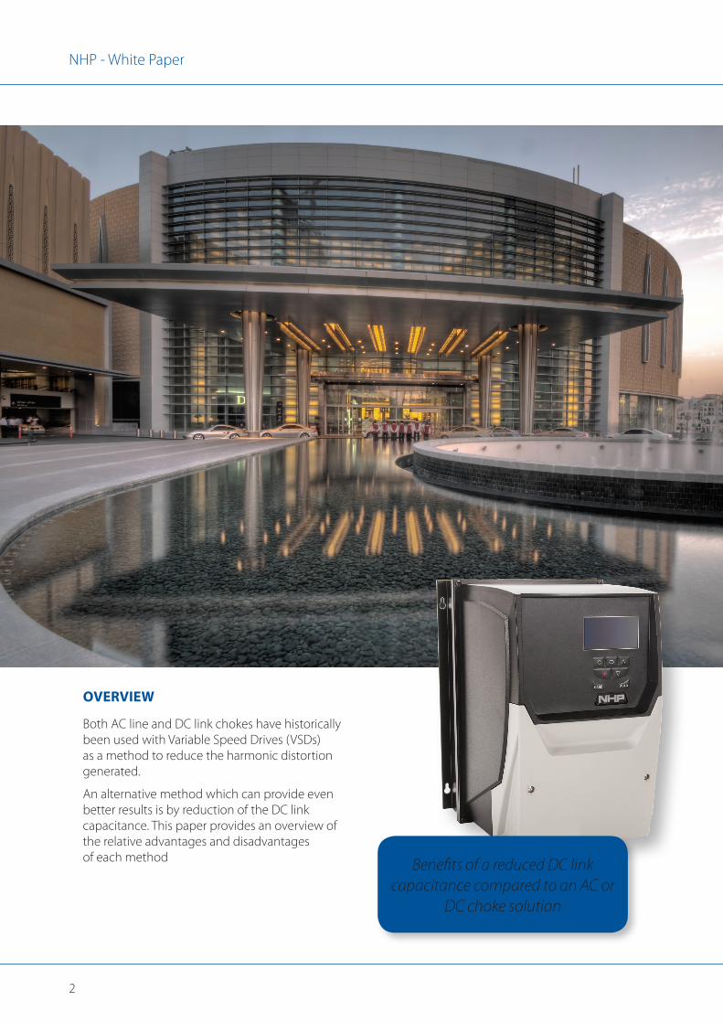
OVERVIEW
Both AC line and DC link chokes have historically been used with Variable Speed Drives (VSDs) as a method to reduce the harmonic distortion generated.
An alternative method which can provide even better results is by reduction of the DC link capacitance. This paper provides an overview of the relative advantages and disadvantages of each method Benefits of a reduced DC link
capacitance compared to an AC or DC choke solution
3
NHP - White Paper
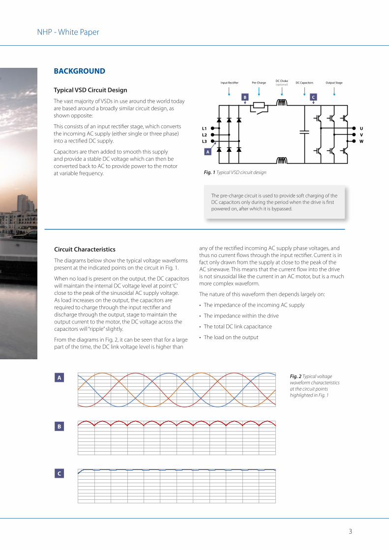
Typical VSD Circuit Design
The vast majority of VSDs in use around the world today are based around a broadly similar circuit design, as shown opposite:
This consists of an input rectifier stage, which converts the incoming AC supply (either single or three phase) into a rectified DC supply.
Capacitors are then added to smooth this supply and provide a stable DC voltage which can then be converted back to AC to provide power to the motor at variable frequency.
The pre-charge circuit is used to provide soft charging of the DC capacitors only during the period when the drive is first powered on, after which it is bypassed.
Circuit Characteristics
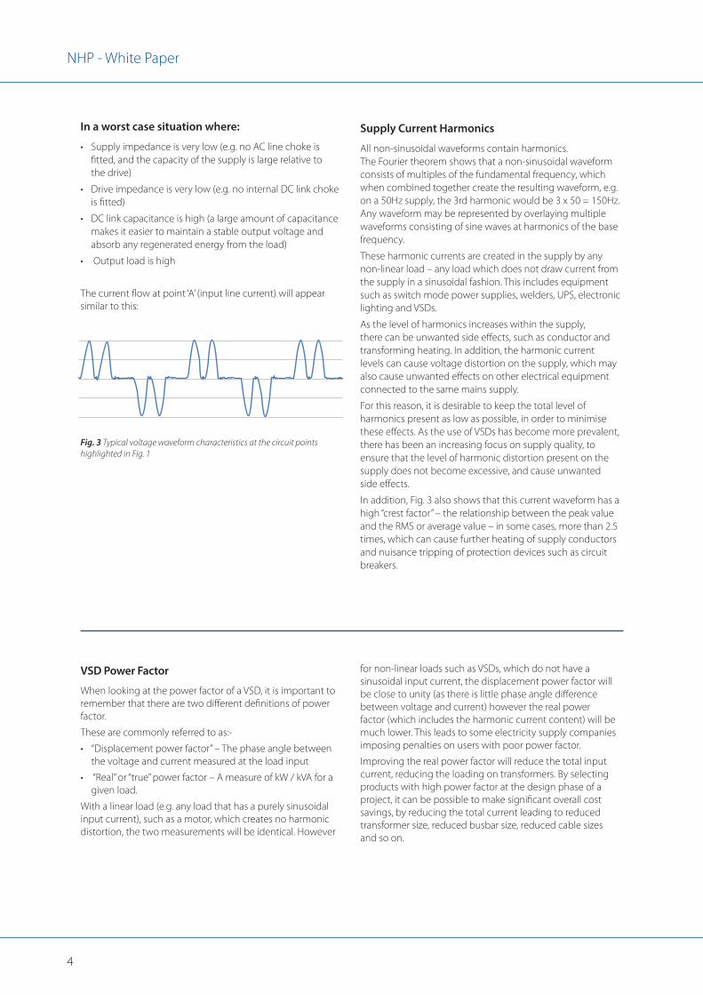
The diagrams below show the typical voltage waveforms present at the indicated points on the circuit in Fig. 1.
When no load is present on the output, the DC capacitors will maintain the internal DC voltage level at point ‘C’ close to the peak of the sinusoidal AC supply voltage. As load increases on the output, the capacitors are required to charge through the input rectifier and discharge through the output, stage to maintain the output current to the motor, the DC voltage across the capacitors will “ripple” slightly.
From the diagrams in Fig. 2, it can be seen that for a large part of the time, the DC link voltage level is higher than
Fig. 2 Typical voltage waveform characteristics at the circuit points highlighted in Fig. 1
Fig. 1 Typical VSD circuit design
UVW
L1
Input Recti�er Pre-Charge Output StageDC CapacitorsDC Choke(optional)
L2L3
A
B C
A
any of the rectified incoming AC supply phase voltages, and thus no current flows through the input rectifier. Current is in fact only drawn from the supply at close to the peak of the AC sinewave. This means that the current flow into the drive is not sinusoidal like the current in an AC motor, but is a much more complex waveform.
The nature of this waveform then depends largely on:
• The impedance of the incoming AC supply
• The impedance within the drive
• The total DC link capacitance
• The load on the output
B
C
BACKGROUND
4
NHP - White Paper
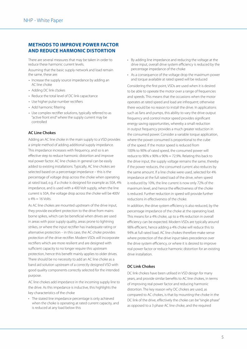
In a worst case situation where:
• Supply impedance is very low (e.g. no AC line choke is fitted, and the capacity of the supply is large relative to the drive)
• Drive impedance is very low (e.g. no internal DC link choke is fitted)
• DC link capacitance is high (a large amount of capacitance makes it easier to maintain a stable output voltage and absorb any regenerated energy from the load)
• Output load is high
The current flow at point ‘A’ (input line current) will appear similar to this:
Supply Current Harmonics
All non-sinusoidal waveforms contain harmonics. The Fourier theorem shows that a non-sinusoidal waveform consists of multiples of the fundamental frequency, which when combined together create the resulting waveform, e.g. on a 50Hz supply, the 3rd harmonic would be 3 x 50 = 150Hz. Any waveform may be represented by overlaying multiple waveforms consisting of sine waves at harmonics of the base frequency.
These harmonic currents are created in the supply by any non-linear load – any load which does not draw current from the supply in a sinusoidal fashion. This includes equipment such as switch mode power supplies, welders, UPS, electronic lighting and VSDs.
As the level of harmonics increases within the supply, there can be unwanted side effects, such as conductor and transforming heating. In addition, the harmonic current levels can cause voltage distortion on the supply, which may also cause unwanted effects on other electrical equipment connected to the same mains supply.
For this reason, it is desirable to keep the total level of harmonics present as low as possible, in order to minimise these effects. As the use of VSDs has become more prevalent, there has been an increasing focus on supply quality, to ensure that the level of harmonic distortion present on the supply does not become excessive, and cause unwanted side effects.
In addition, Fig. 3 also shows that this current waveform has a high “crest factor” – the relationship between the peak value and the RMS or average value – in some cases, more than 2.5 times, which can cause further heating of supply conductors and nuisance tripping of protection devices such as circuit breakers.
VSD Power Factor
When looking at the power factor of a VSD, it is important to remember that there are two different definitions of power factor.
These are commonly referred to as:-
• “Displacement power factor” – The phase angle between the voltage and current measured at the load input
• “Real” or “true” power factor – A measure of kW / kVA for a given load.
With a linear load (e.g. any load that has a purely sinusoidal input current), such as a motor, which creates no harmonic distortion, the two measurements will be identical. However
for non-linear loads such as VSDs, which do not have a sinusoidal input current, the displacement power factor will be close to unity (as there is little phase angle difference between voltage and current) however the real power factor (which includes the harmonic current content) will be much lower. This leads to some electricity supply companies imposing penalties on users with poor power factor.
Improving the real power factor will reduce the total input current, reducing the loading on transformers. By selecting products with high power factor at the design phase of a project, it can be possible to make significant overall cost savings, by reducing the total current leading to reduced transformer size, reduced busbar size, reduced cable sizes and so on.
Fig. 3 Typical voltage waveform characteristics at the circuit points highlighted in Fig. 1
5
NHP - White Paper
There are several measures that may be taken in order to reduce these harmonic current levels.
Assuming that the basic supply network and load remain the same, these are:
• Increase the supply source impedance by adding an AC line choke
• Adding DC link chokes
• Reduce the total level of DC link capacitance
• Use higher pulse number rectifiers
• Add harmonic filtering
• Use complex rectifier solutions, typically referred to as “active front end” where the supply current may be controlled
AC Line Chokes
Adding an AC line choke in the main supply to a VSD provides a simple method of adding additional supply impedance. This impedance increases with frequency, and so is an effective step to reduce harmonic distortion and improve real power factor. AC line chokes in general can be easily added to existing installations. Typically, AC line chokes are selected based on a percentage impedance – this is the percentage of voltage drop across the choke when operating at rated load, e.g. if a choke is designed for example as 50A, 4% impedance, and is used with a 400 Volt supply, when the line current is 50A, the voltage drop across the choke will be 400V x 4% = 16 Volts.
As AC line chokes are mounted upstream of the drive input, they provide excellent protection to the drive from mains borne spikes, which can be beneficial when drives are used in areas with poor supply quality, areas prone to lightning strikes, or where the input rectifier has inadequate rating or alternative protection – in this case, the AC choke provides protection of the drive rectifier. Modern VSDs will incorporate rectifiers which are more resilient and are designed with sufficient capacity to no longer require this upstream protection, hence this benefit mainly applies to older drives. There should be no necessity to add an AC line choke as a band aid solution upstream of a correctly designed VSD with good quality components correctly selected for the intended purpose.
AC line chokes add impedance in the incoming supply line to the drive. As this impedance is inductive, this highlights the key characteristics of the choke
• The stated line impedance percentage is only achieved when the choke is operating at rated current capacity, and is reduced at any load below this
• By adding line impedance and reducing the voltage at the drive input, overall drive system efficiency is reduced by the percentage impedance of the choke
• As a consequence of the voltage drop the maximum power and torque available at rated speed will be reduced
Considering the first point, VSDs are used when it is desired to be able to operate the motor over a range of frequencies and speeds. This means that the occasions when the motor operates at rated speed and load are infrequent; otherwise there would be no reason to install the drive. In applications such as fans and pumps, this ability to vary the drive output frequency and control motor speed provides significant energy saving opportunities, whereby a small reduction in output frequency provides a much greater reduction in the consumed power. Consider a variable torque application, where the power consumed is proportional to the cube of the speed. If the motor speed is reduced from 100% to 90% of rated speed, the consumed power will reduce to 90% x 90% x 90% = 72.9%. Relating this back to the drive input, the supply voltage remains the same, thereby if the power reduces, the consumed current also reduces by the same amount. If a line choke were used, selected for 4% impedance at the full rated load of the drive, when speed is reduced by 10%, the line current is now only 72% of the maximum level, and hence the effectiveness of the choke is reduced. Further reduction in speed will provide further reductions in effectiveness of the choke.
In addition, the drive system efficiency is also reduced, by the percentage impedance of the choke at the operating load. This means for a 4% choke, up to a 4% reduction in overall efficiency can be expected. Modern VSDs are typically around 98% efficient, hence adding a 4% choke will reduce this to 94% at full rated load. AC line chokes therefore make sense where protection of the drive input takes precedence over the drive system efficiency, or where it is desired to improve real power factor or reduce harmonic distortion for an existing drive installation.
DC Link Chokes
DC link chokes have been utilised in VSD design for many years, and provide similar benefits to AC line chokes, in terms of improving real power factor and reducing harmonic distortion. The key reason why DC chokes are used, as compared to AC chokes, is that by mounting the choke in the DC link of the drive, effectively the choke can be “single phase” as opposed to a 3 phase AC line choke, and the required
METHODS TO IMPROVE POWER FACTOR AND REDUCE HARMONIC DISTORTION
6
NHP - White Paper
inductance can be reduced, due to the choke being after the input rectifier and so the effective supply frequency is increased by six (each incoming AC supply phase has two peaks, and when all three phases are rectified, the DC ripple frequency is therefore six times the AC line frequency). This allows a reduction in size, weight and overall cost of the choke. In general, DC link chokes provide similar benefits to AC line chokes, in terms of reducing harmonic currents and improving Real Power Factor, however as the choke is now mounted after the input rectifier,no additional protection against spikes on the AC supply is provided. In general, this is not a concern, as drives designed with internal DC link chokes will have a rectifier circuit designed, rated and protected to ensure it is not easily damaged in this way.
DC link chokes will have an overall negative impact on drive system efficiency. As the inductance is typically lower than an AC choke, the increase in losses is relatively lower, however there is still an overall drive system efficiency reduction when a DC link choke is used, particularly with non-linear or saturated chokes (sometimes referred to as “swinging” chokes), where the inductance can change with current.
In addition, the choke effectiveness, as with an AC line choke, is reduced with reducing load. Swinging chokes attempt to counter this by utilising a design which improves effectiveness at part load, however the effectiveness is still less than full load.
It can be seen from the description earlier that the design of a VSD with large DC link capacitance will always lead to high levels of harmonic currents. Historically, the large capacitance was necessary to provide a stable DC power supply inside the VSD which could be used to create the three phase output for the motor.
The reduced DC link capacitance is achieved by using film capacitor technology as opposed to the electrolytic capacitors used in conventional VSDs. Additional benefits of the film capacitor technology include a longer capacitor lifetime and removing the need for capacitor reforming.
Recent technology advances now allow significant reduction in the DC link capacitance of a VSD whilst improving overall efficiency, at the same time, this technology, also maintains excellent motor control whilst providing a significant reduction in full and part load harmonics.
Improvements in modern day IGBTs allow the use of the higher switching frequencies required to achieve the
necessary control without sacrificing overall efficiency. There are limitations, in that the technology can only be readily applied up to around 100 Amps load current at present, as above this current, the heat losses from the IGBT are too great, and result in unacceptable efficiency reduction, however below this point, the gains are significant.
The benefit of reducing the DC link capacitance is a significant reduction in supply current harmonics at full and part load, which is of much more practical benefit since the majority of operation will be at part load. In addition, there is no reduction in the reliability of the design or resistance to mains voltage fluctuations, spikes or notches compared to a drive designed with a DC link choke, since a DC choke is not effective in these areas.
By utilising higher PWM switching frequency, there are additional benefits such as reduced audible noise from the motor without derating.
MODDRIVE REDUCED DC LINK CAPACITANCE
7
NHP - White Paper
CONCLUSION
Fig. 4 Typical iTHD values at full and part load
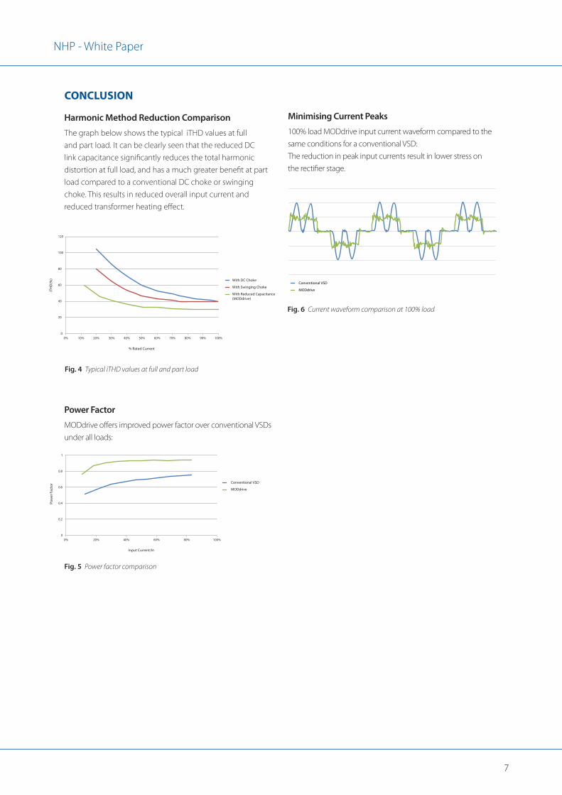
Harmonic Method Reduction Comparison
The graph below shows the typical iTHD values at full and part load. It can be clearly seen that the reduced DC link capacitance significantly reduces the total harmonic distortion at full load, and has a much greater benefit at part load compared to a conventional DC choke or swinging choke. This results in reduced overall input current and reduced transformer heating effect.
Fig. 5 Power factor comparison
Power Factor
MODdrive offers improved power factor over conventional VSDs under all loads:
Fig. 6 Current waveform comparison at 100% load
Minimising Current Peaks
100% load MODdrive input current waveform compared to the same conditions for a conventional VSD: The reduction in peak input currents result in lower stress on the rectifier stage.
Conventional VSD
MODdrive
0
20
40
60
80
100
120
0% 10% 20% 30% 40% 50% 60% 70% 80% 90% 100%
With DC Choke
With Swinging Choke
With Reduced Capacitance (MODdrive)
iTH
D(%
)
% Rated Current
0
0.2
0.4
0.6
0.8
1
0% 20% 40% 60% 80% 100%
Conventional VSD
MODdrive
Pow
er F
acto
r
Input Current/In

NHP Electrical Engineering Products Pty LtdA.B.N. 84 004 304 812
NHPMODDRIVEWP 02/16 © Copyright NHP 2016
AUSTRALIAnhp.com.au
SALES 1300 NHP NHP
VICTORIAMelbourne 43-67 River Street Richmond VIC 3121 Tel +61 3 9429 2999
Laverton 104-106 William Angliss Drive Laverton North VIC 3026 Tel +61 3 9368 2901
Dandenong Unit 1/80 Monash Drive Dandenong South VIC 3175 Tel +61 3 8773 6400 Fax 1300 647 329
TASMANIAHobart 29B Lampton Ave Derwent Park TAS 7009 Tel +61 3 6228 9575 Fax +61 3 6228 9757
Launceston Unit 3 13-17 Merino Street Kings Meadows TAS 7249 Tel +61 3 6345 2600 Fax +61 3 6344 6324
SOUTH AUSTRALIAAdelaide 36-38 Croydon Road Keswick SA 5035 Tel +61 8 8297 9055
NEW SOUTH WALESSydney 30-34 Day Street North Silverwater NSW 2128 Tel +61 2 9748 3444
Newcastle 575 Maitland Road Mayfield West NSW 2304 Tel +61 2 4960 2220 Fax +61 2 4960 2203
Wollongong Unit 3 1 Resolution Drive Unanderra NSW 2526 Tel 1300 647 647 Fax 1300 647 329
Albury / Wodonga 847 Ramsden Drive Albury NSW 2640 Tel +61 2 6049 0600 Fax +61 3 6025 0592
ACTCanberra Unit 1 187 Gladstone Street Fyshwick ACT 2609 Tel +61 2 6280 9888 Fax +61 2 6280 9588
WESTERN AUSTRALIAPerth 38 Belmont Ave Rivervale WA 6103 Tel +61 8 9277 1777
NORTHERN TERRITORYDarwin 3 Steele Street Winnellie NT 0820 Tel +61 8 8947 2666 Fax +61 8 8947 2049
QUEENSLANDBrisbane 16 Riverview Place Murarrie QLD 4172 Tel +61 7 3909 4999
Townsville 5 Leyland Street Garbutt QLD 4814 Tel +61 7 4779 0700 Fax +61 7 4775 1457
Rockhampton 1 Lawson Street Parkhurst QLD 4702 Tel +61 7 4927 2277 Fax +61 7 4922 2947
Toowoomba Cnr Carroll Street and Struan Court QLD 4350 Tel +61 7 4634 4799 Fax +61 7 4633 1796
Cairns Unit 2 1 Bramp Close Portsmith QLD 4870 Tel +61 7 4035 6888 Fax +61 7 4035 6999
NEW ZEALANDnhp-nz.com
SALES 0800 NHP NHP
PO Box 62-009 Sylvia Park Auckland 1644 New Zealand
Auckland 118a Carbine Road Mt Wellington 1060
Hamilton 78 Rostrevor Street Hamilton 3204
Napier 126 Taradale Road Onekawa 4110
Wellington Unit B4, 59 Marsden Street Melling Lower Hutt 5010
Christchurch 27 Iversen Terrace Waltham 8011
Dunedin 30 Fox StreetSouth Dunedin 9012
For more information, scan to download the NHP eCatalogues App o�ering exclusive video content, catalogues and literature!