Reduced Certification Costs for Trusted Multi- core...
88
ARTEMIS JU ARTEMIS-2009-1 Reduced Certification Costs for Trusted Multi- core Platforms (RECOMP) Deliverable 2.1 Component model specification Nature: Report Dissemination Level: Public Grant Agreement number: 100202 Project acronym: RECOMP Project title: Reduced Certification Costs for Trusted Multi-core Platforms Funding Scheme: ARTEMIS JU Period covered: From 1/04/2010 to 31/03/2011 Contact persons (name, organisation, e-mail) Project coordinator: Jarkko Mäkitalo, KONE, [email protected] Task Leader: Kaisa Sere, AAU, [email protected] WP coordinator: Paul Pop, DTU, [email protected] Project website address: http://atc.ugr.es/recomp/
Transcript of Reduced Certification Costs for Trusted Multi- core...

ARTEMIS JU
ARTEMIS-2009-1
Reduced Certification Costs for Trusted Multi-
core Platforms (RECOMP)
Deliverable 2.1
Component model specification
Nature: Report Dissemination Level: Public
Grant Agreement number: 100202
Project acronym: RECOMP
Project title: Reduced Certification Costs for Trusted Multi-core Platforms
Funding Scheme: ARTEMIS JU
Period covered: From 1/04/2010 to 31/03/2011
Contact persons (name, organisation, e-mail)
Project coordinator: Jarkko Mäkitalo, KONE, [email protected]
Task Leader: Kaisa Sere, AAU, [email protected]
WP coordinator: Paul Pop, DTU, [email protected]
Project website address: http://atc.ugr.es/recomp/
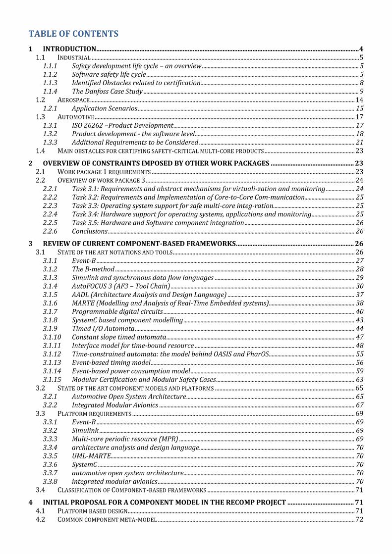
TABLE OF CONTENTS
1 INTRODUCTION .............................................................................................................................................................. 4 1.1 INDUSTRIAL .................................................................................................................................................................................. 5
1.1.1 Safety development life cycle – an overview .............................................................................................................. 5 1.1.2 Software safety life cycle ..................................................................................................................................................... 5 1.1.3 Identified Obstacles related to certification ............................................................................................................... 8 1.1.4 The Danfoss Case Study ....................................................................................................................................................... 9
1.2 AEROSPACE ................................................................................................................................................................................ 14 1.2.1 Application Scenarios ........................................................................................................................................................ 15
1.3 AUTOMOTIVE ............................................................................................................................................................................. 17 1.3.1 ISO 26262 –Product Development ............................................................................................................................... 17 1.3.2 Product development - the software level ................................................................................................................ 18 1.3.3 Additional Requirements to be Considered ............................................................................................................. 21
1.4 MAIN OBSTACLES FOR CERTIFYING SAFETY-CRITICAL MULTI-CORE PRODUCTS ............................................................ 23
2 OVERVIEW OF CONSTRAINTS IMPOSED BY OTHER WORK PACKAGES .................................................. 23 2.1 WORK PACKAGE 1 REQUIREMENTS ....................................................................................................................................... 23 2.2 OVERVIEW OF WORK PACKAGE 3 ........................................................................................................................................... 24
2.2.1 Task 3.1: Requirements and abstract mechanisms for virtuali-zation and monitoring .................... 24 2.2.2 Task 3.2: Requirements and Implementation of Core-to-Core Com-munication................................... 25 2.2.3 Task 3.3: Operating system support for safe multi-core integ-ration ......................................................... 25 2.2.4 Task 3.4: Hardware support for operating systems, applications and monitoring .............................. 25 2.2.5 Task 3.5: Hardware and Software component integration ............................................................................. 26 2.2.6 Conclusions ............................................................................................................................................................................. 26
3 REVIEW OF CURRENT COMPONENT-BASED FRAMEWORKS ....................................................................... 26 3.1 STATE OF THE ART NOTATIONS AND TOOLS ......................................................................................................................... 26
3.1.1 Event-B ..................................................................................................................................................................................... 27 3.1.2 The B-method ........................................................................................................................................................................ 28 3.1.3 Simulink and synchronous data flow languages .................................................................................................. 29 3.1.4 AutoFOCUS 3 (AF3 – Tool Chain) ................................................................................................................................. 30 3.1.5 AADL (Architecture Analysis and Design Language) ......................................................................................... 37 3.1.6 MARTE (Modelling and Analysis of Real-Time Embedded systems) ............................................................ 38 3.1.7 Programmable digital circuits ...................................................................................................................................... 40 3.1.8 SystemC based component modelling ........................................................................................................................ 43 3.1.9 Timed I/O Automata .......................................................................................................................................................... 44 3.1.10 Constant slope timed automata .................................................................................................................................... 47 3.1.11 Interface model for time-bound resource ................................................................................................................ 48 3.1.12 Time-constrained automata: the model behind OASIS and PharOS ............................................................ 55 3.1.13 Event-based timing model ............................................................................................................................................... 56 3.1.14 Event-based power consumption model ................................................................................................................... 59 3.1.15 Modular Certification and Modular Safety Cases ................................................................................................. 63
3.2 STATE OF THE ART COMPONENT MODELS AND PLATFORMS ............................................................................................. 65 3.2.1 Automotive Open System Architecture ...................................................................................................................... 65 3.2.2 Integrated Modular Avionics ......................................................................................................................................... 67
3.3 PLATFORM REQUIREMENTS .................................................................................................................................................... 69 3.3.1 Event-B ..................................................................................................................................................................................... 69 3.3.2 Simulink ................................................................................................................................................................................... 69 3.3.3 Multi-core periodic resource (MPR) ........................................................................................................................... 69 3.3.4 architecture analysis and design language ............................................................................................................. 70 3.3.5 UML-MARTE ........................................................................................................................................................................... 70 3.3.6 SystemC .................................................................................................................................................................................... 70 3.3.7 automotive open system architecture........................................................................................................................ 70 3.3.8 integrated modular avionics .......................................................................................................................................... 70
3.4 CLASSIFICATION OF COMPONENT-BASED FRAMEWORKS .................................................................................................. 71
4 INITIAL PROPOSAL FOR A COMPONENT MODEL IN THE RECOMP PROJECT ........................................ 71 4.1 PLATFORM BASED DESIGN ....................................................................................................................................................... 71 4.2 COMMON COMPONENT META-MODEL ................................................................................................................................... 72

4.3 COMPONENT TYPES .................................................................................................................................................................. 72 4.4 COMPONENT META-MODELS .................................................................................................................................................. 72 4.5 FUNCTIONAL COMPONENT ...................................................................................................................................................... 72 4.6 ASPECTS ..................................................................................................................................................................................... 73 4.7 USE OF THE META-MODEL ....................................................................................................................................................... 73
4.7.1 Example .................................................................................................................................................................................... 73
5 CONCLUSION AND FUTURE WORK IN WP2 ....................................................................................................... 75
6 APPENDIX ...................................................................................................................................................................... 75 6.1 THE DANFOSS CASE STUDY – REQUIREMENTS .................................................................................................................... 75 6.2 COMPONENT FRAMEWORK CLASSIFICATION ........................................................................................................................ 84
1 INTRODUCTION The goal of work package 2 is to improve state of the art concerning component-based technology with the
purpose of developing reliable mixed-criticality systems that runs on multi-core platforms. The first part of the
deliverable contains a survey of on one hand the requirements from industrial partners that develops safety critical
systems and on the other of available tools and methods. Thus we have a both a top-down and a bottom up
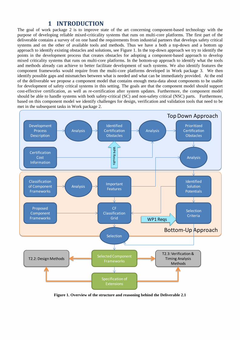
approach to identify existing obstacles and solutions, see Figure 1. In the top-down approach we try to identify the
points in the development process that creates obstacles for adopting a component-based approach to develop
mixed criticality systems that runs on multi-core platforms. In the bottom-up approach to identify what the tools
and methods already can achieve to better facilitate development of such systems. We also identify features the
component frameworks would require from the multi-core platforms developed in Work package 3. We then
identify possible gaps and mismatches between what is needed and what can be immediately provided. At the end
of the deliverable we propose a component model that contains enough meta-data about components to be usable
for development of safety critical systems in this setting. The goals are that the component model should support
cost-effective certification, as well as re-certification after system updates. Furthermore, the component model
should be able to handle systems with both safety-critical (SC) and non-safety critical (NSC) parts. Furthermore,
based on this component model we identify challenges for design, verification and validation tools that need to be
met in the subsequent tasks in Work package 2.
Figure 1. Overview of the structure and reasoning behind the Deliverable 2.1
Bottom-Up Approach
Top Down Approach
DevelopmentProcess
DescriptionAnalysis
IdentifiedCertification
ObstaclesAnalysis
CertificationCost
Information
PrioritizedCertification
Obstacles
ProposedComponentFrameworks
Classification of ComponentFrameworks
AnalysisImportant Features
Analysis
IdentifiedSolution
Potentials
CF Classification
Grid
Selected ComponentFrameworks
SelectionCriteria
WP
4 R
esu
lts
WP1 Reqs
Selection
T2.2: Design MethodsT2.3: Verification &
Timing Analysis Methods
Specification of Extensions

1.1 INDUSTRIAL
The following subsections give a short description of the Safety Development Life Cycle, with special focus on the
documents produced and tools used during the software development life cycle. The Safety Development Life
Cycle is followed by a section on the identified obstacles related to the development process, see section 1.1.3.
The Danfoss case study is described in section 1.1.4; providing a small and realistic case study to be used by
RECOMP partners to pre-evaluate the developed development methods, tools and platform. The high-level
requirements related to the case study can be found in section 6.1.
1.1.1 SAFETY DEVELOPMENT LIFE CYCLE – AN OVERVIEW
The safety development life cycle used at Danfoss Power Electronics in Figure 2. Phase 1 and 2 are related to the
conceptualisation and system requirement specification.
In phase 2, the system qualification test specification is also started and further extended during the complete
safety development life cycle and these tests are carried out in phase 3 after the hardware, user documentation and
software development life cycle are finalized.
After phase 2, the hardware, user documentation and software development phases are started. The following
chapters provide detailed information about the documents and tools used in the software development phase.
Figure 2. Safety Development Life Cycle
1.1.2 SOFTWARE SAFETY LIFE CYCLE
Figure 3, illustrates phases 1, 2, 31 to 37 of the safety development life cycle. The figure lists on the right hand side
the tools that are used in the various steps of the life cycle, where as the left hand side lists the output.
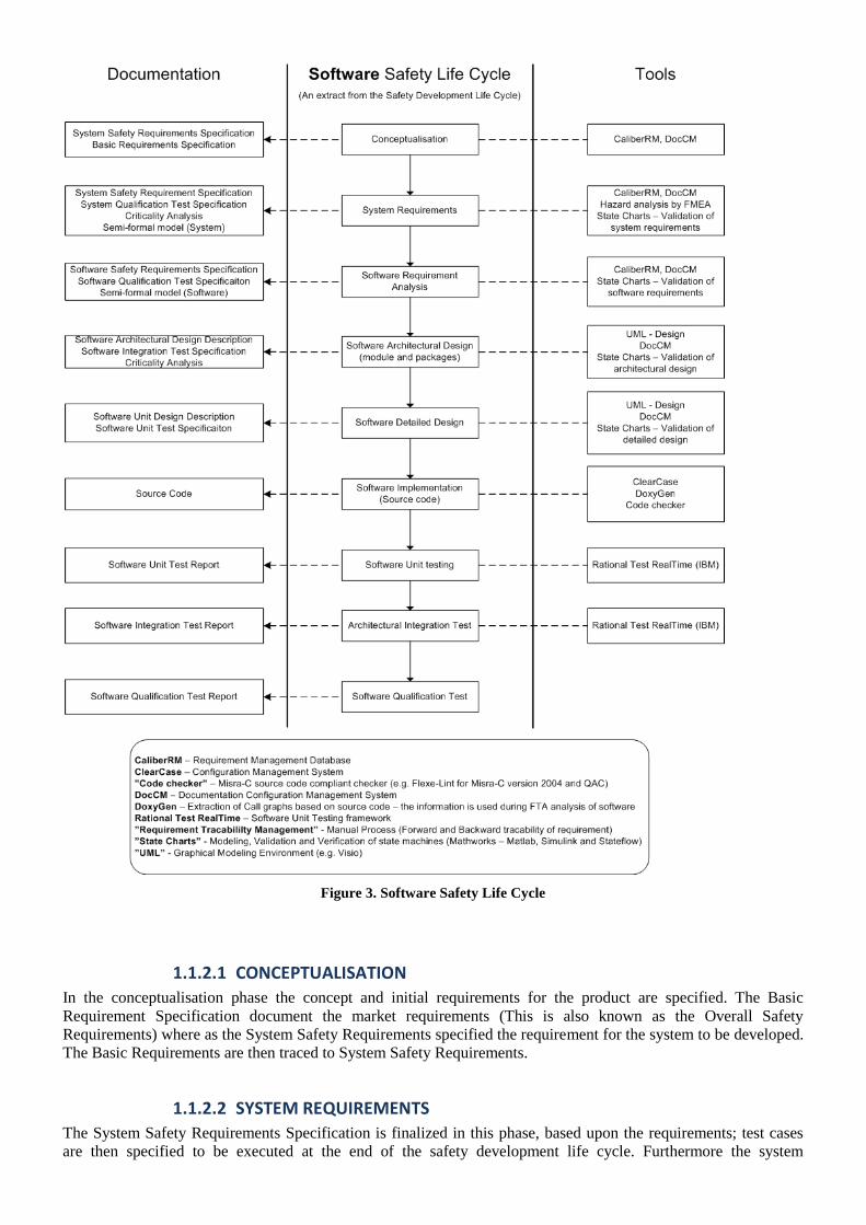
Figure 3. Software Safety Life Cycle
1.1.2.1 CONCEPTUALISATION
In the conceptualisation phase the concept and initial requirements for the product are specified. The Basic
Requirement Specification document the market requirements (This is also known as the Overall Safety
Requirements) where as the System Safety Requirements specified the requirement for the system to be developed.
The Basic Requirements are then traced to System Safety Requirements.
1.1.2.2 SYSTEM REQUIREMENTS
The System Safety Requirements Specification is finalized in this phase, based upon the requirements; test cases
are then specified to be executed at the end of the safety development life cycle. Furthermore the system

requirements are modelled using Simulink/Stateflow, in order to represent the behaviour of the system. This
provides an animated model of the system and is used to validate the system requirements.
The System Qualification Test Cases are converted into test vectors for input to the Simulink model, in order to
validate the model as well as the test case. The derived model coverage information is then used to identify
additional test cases.
Traceability between the System Safety Requirements and the System Qualification Test Cases as well as the
Simulink/Stateflow model is made at this step.
The System Model (as well as the Software Model) is only used for modelling the requirements and not for code
generation.
1.1.2.3 SOFTWARE REQUIREMENT ANALYSIS
The Software Safety Requirements are based upon the System Safety Requirement. Similar to the System Safety
Requirements, the Software Safety Requirements are modelled in Simulink/Stateflow (The system model can be
largely reused in this step) the difference between the system and software model is that the software model,
models the hardware architecture of the system (e.g. redundant processor system). The software model is similarly
validated using the System Qualification Test Cases.
Test cases are derived from the Software Safety Requirements and used in Software Qualification Test to validate
the software integrated on the hardware.
Traceability between the System Safety Requirements and Software Safety Requirements, Software Safety
Requirements and Software Qualification Test Cases, and Simulink/Stateflow model is made at this step.
1.1.2.4 SOFTWARE ARCHITECTURAL DESIGN
The software architecture is designed in this step, based upon the Software Safety Requirements. The Software
Model is used as input to the software architectural design and to validate the architecture using the possibility to
animate the model. The software architecture is represented using UML diagrams. The Software Integration Test
Specification describes the tests to be evaluated at the Architectural Integration Test.
Traceability between Software Safety Requirements and Software Architectural Design Description, as well as
Software Integration Test Specification made in this step.
1.1.2.5 SOFTWARE DETAILED DESIGN
The Software Unit Design Description documents the software units in detail, using sequence diagrams, flow
charts. The Software Model is used as input to the detailed design as well as to validate the design.
The Software Unit Test Specification specifies the unit tests to be evaluated in Software Unit Testing.
Traceability between the Software Architectural Design Description and Software Unit Design Description is made
in this step.
1.1.2.6 SOFTWARE IMPLEMENTATION
The Source Code is written based upon the Software Unit Design Description.
Traceability between Software Safety Requirements, Software Unit Design Description to the Source Code
1.1.2.7 SOFTWARE UNIT TESTING
The Source Code written in the previous step is validated using the Software Unit Test Specification. The derived
coverage information is then used to determine if further unit tests are necessary.
The results of the unit tests are documented in Software Unit Test Report.

Traceability between Software Unit Test Specification and Software Unit Test Report is made in this step.
1.1.2.8 ARCHITECTURAL INTEGRATION TEST
The validated software units from the previous step are combined based upon the Software Integration Test
Specification and the test results are documented in Software Integration Test Report.
Traceability between Software Integration Test Specification and Software Integration Test Report is made in this
step.
1.1.2.9 SOFTWARE QUALIFICATION TEST
The software is executed on the hardware (from step 26 of the safety development life cycle) and the software is
validated against the Software Qualification Test Specification. The results are documented in the Software
Qualification Test Report.
Traceability between Software Qualification Test Specification and Software Qualification Test Report is made in
this step.
After passing the last step of the software safety life cycle then System Qualification Test is done.
1.1.3 IDENTIFIED OBSTACLES RELATED TO CERTIFICATION
The obstacles related to the development and certification of safety related products for the industrial market:
Minimising the number/amount of development artefacts to the absolute minimum required for certification
In order to reduce certification costs, it is necessary only to provide the certification authority with the
necessary documentation. Keeping the certification authority focused on safety related parts of the product.
Guidance handling mixed criticality applications in a design tool, it is therefore important that the design
tool also provide means for separating the design documentation related to the different criticality levels.
Limited exchange of data/information between tools applied during development
The exchange of data between development tools in a tool-chain is usually low and therefore information
needs to be manually passed from one tool to the other.
A solution could be a component model that allows exchange between different tools.
Traceability between development artefacts
Tracing requirements from the requirements specification to source code and test cases/reports is usually
handled manually.
Minimising the complexity of the safety related system, due to integration of online diagnostic techniques
and measures
For example one of the diagnostic techniques that can be applied is program sequence monitoring, where
the execution of the program is monitored. This usually implies that the implementation of the safety
functions is enhanced with additional functionality to support the diagnostic technique.
A solution to this could be to design templates for components such that integration of diagnostic
techniques becomes a seamless operation.
Reusing software components
Reusability issues, for example when information is scattered around in different tools/systems, therefore
reuse is often difficult. Information related to a component could be: Requirements, Design, Test cases and
reports.
A solution to this could be to include reference to these as part of the component in the component library.
Component mining
Identifying existing components (Hardware and software) with an organisation, to increase reuse and avoid
that functionality is implemented twice.
Time consuming part of the development phase:

Maintenance of development artefacts, such as requirements specification, design documents, test
specifications, traceability information, etc. Due to requirement changes, design issues, etc.
Validation – Unit testing, integration testing, qualification testing
Recommendation for component meta-data:
Unique ID – To ease identification within component library
Version number
Name – Name of the component
Description – Description of the functionality provided by the component
References to requirements fulfilled by the component
References to test cases – Tests applied to verify the component
Safety Integrity Level (SIL) – The SIL capability of the component
Functionality – Safety related – the component implemented functionality related to the safety function,
Diagnostic – the component implements diagnostic function, Non-safety related – the functionality
provided by the component is non-safety related (―SIL0‖)
Rules/Restrictions – Specify rules/restrictions that have to be followed in order to reuse the particular
component
Besides the above meta data, the tool platform shall also provide,
functionality to handle separation between components (e.g. grouping of components),
schedulability analysis,
Worst Case Execution Time (WCET) analysis,
Component mining is another important functionality that is highly recommended, to identify existing
components.
Code generation
Applying component-based methodology and component-based mindset during the Safety Development Life
Cycle is believed to improve the reuse and testability of the developed system. It is expected that a component-
based methodology will help reduce the development as well as certification and re-certification costs.
1.1.4 THE DANFOSS CASE STUDY
The Danfoss Case Study is a small but realistic case study provided to RECOMP, for evaluation of development
methods, tools and hardware platform. The case study will be used by Danfoss as the foundation for the
demonstrator developed as part of work package 5.
The following subsection provides a short description of the taxonomy used to model the safety related
architectures of the case study.
1.1.4.1 TAXONOMY
This chapter provides a short description of the taxonomy used in this document to model the safety related
architecture.
The taxonomy from Table 1 is used to classify the elements of the safety related architecture and enables an
element to be represented as either, ―Safe‖, ―Diagnostic‖ or ―Non-safe‖ and are further refined as implemented in
either hardware (Physical) or software (Virtual). This makes it possible to clearly differentiate between the
elements of the architecture – e.g. a sensor that is part of a safety function (solid line) from a sensor used for
diagnostic purposes (dotted line).
A number of typical elements have been identified and listed in Table 2 some of the elements are general (e.g.
Sensor, Actuator, Final element actuator, Processor and Bus) where others are specific (e.g. Diagnostic, Safe
channel, Fail safe sensor and Fail safe actuator). General elements can in principle be represented as one of the
three functions from the taxonomy; whereas the specific elements are limited to either ―safe‖ or ―diagnostic‖.
Table 2 lists the elements that we have used with success in the development of this taxonomy and do not represent
a final list of elements.
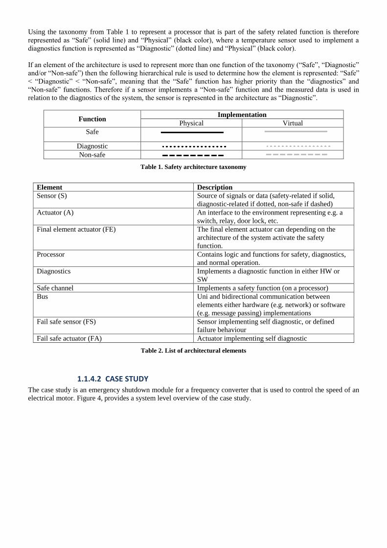
Using the taxonomy from Table 1 to represent a processor that is part of the safety related function is therefore
represented as ―Safe‖ (solid line) and ―Physical‖ (black color), where a temperature sensor used to implement a
diagnostics function is represented as ―Diagnostic‖ (dotted line) and ―Physical‖ (black color).
If an element of the architecture is used to represent more than one function of the taxonomy (―Safe‖, ―Diagnostic‖
and/or ―Non-safe‖) then the following hierarchical rule is used to determine how the element is represented: ―Safe‖
< ―Diagnostic‖ < ―Non-safe‖, meaning that the ―Safe‖ function has higher priority than the ―diagnostics‖ and
―Non-safe‖ functions. Therefore if a sensor implements a ―Non-safe‖ function and the measured data is used in
relation to the diagnostics of the system, the sensor is represented in the architecture as ―Diagnostic‖.
Function Implementation
Physical Virtual
Safe
Diagnostic
Non-safe
Table 1. Safety architecture taxonomy
Element Description
Sensor (S) Source of signals or data (safety-related if solid,
diagnostic-related if dotted, non-safe if dashed)
Actuator (A) An interface to the environment representing e.g. a
switch, relay, door lock, etc.
Final element actuator (FE) The final element actuator can depending on the
architecture of the system activate the safety
function.
Processor Contains logic and functions for safety, diagnostics,
and normal operation.
Diagnostics Implements a diagnostic function in either HW or
SW
Safe channel Implements a safety function (on a processor)
Bus Uni and bidirectional communication between
elements either hardware (e.g. network) or software
(e.g. message passing) implementations
Fail safe sensor (FS) Sensor implementing self diagnostic, or defined
failure behaviour
Fail safe actuator (FA) Actuator implementing self diagnostic
Table 2. List of architectural elements
1.1.4.2 CASE STUDY
The case study is an emergency shutdown module for a frequency converter that is used to control the speed of an
electrical motor. Figure 4, provides a system level overview of the case study.

Figure 4. Danfoss Case Study
The sensor subsystem consists of an emergency switch, a safe field bus1 and a reset switch. The reset switch is used
to reset the safety functions in case of a power cycle and/or the activation of the safety function (this does not
include the activation via the safe field bus). The emergency switch and the safe field bus are used to activate the
safety function. The logical subsystem consists of the non-safety related part that implements a gateway to/from a
CAN network for the operational data transmitted over the safe field bus and the safety related part that
implements the safety function and the diagnostic measures. The final element subsystem implements two
independent ways to activate the safety function of the system.
The emergency shutdown module provides two safety functions, the Safe Torque Off (STO) and the Safe Stop 1
(SS1). The STO will coast (e.g. removes the torque on the motor) the electrical motor that is controlled by the
frequency converter and the SS1 will after a configurable delay activate the STO function.
The next two chapters show how such a system would normally be implemented using redundant processors and a
multi-core chip.
1.1.4.3 TYPICAL CONCEPT
The system is typically implemented using redundant processors as illustrated in Figure 5.
1 Safe field bus, enable safety related components to exchange safely safety related information. E.g. ProfiSafe.
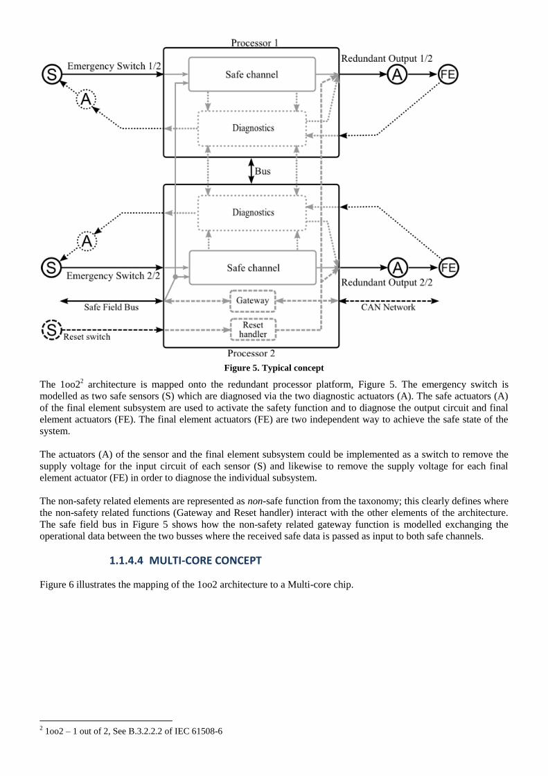
Figure 5. Typical concept
The 1oo22 architecture is mapped onto the redundant processor platform, Figure 5. The emergency switch is
modelled as two safe sensors (S) which are diagnosed via the two diagnostic actuators (A). The safe actuators (A)
of the final element subsystem are used to activate the safety function and to diagnose the output circuit and final
element actuators (FE). The final element actuators (FE) are two independent way to achieve the safe state of the
system.
The actuators (A) of the sensor and the final element subsystem could be implemented as a switch to remove the
supply voltage for the input circuit of each sensor (S) and likewise to remove the supply voltage for each final
element actuator (FE) in order to diagnose the individual subsystem.
The non-safety related elements are represented as non-safe function from the taxonomy; this clearly defines where
the non-safety related functions (Gateway and Reset handler) interact with the other elements of the architecture.
The safe field bus in Figure 5 shows how the non-safety related gateway function is modelled exchanging the
operational data between the two busses where the received safe data is passed as input to both safe channels.
1.1.4.4 MULTI-CORE CONCEPT
Figure 6 illustrates the mapping of the 1oo2 architecture to a Multi-core chip.
2 1oo2 – 1 out of 2, See B.3.2.2.2 of IEC 61508-6
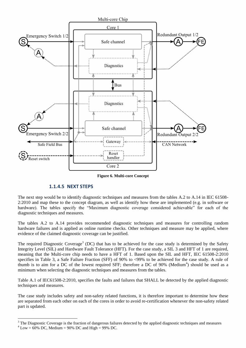
Figure 6. Multi-core Concept
1.1.4.5 NEXT STEPS
The next step would be to identify diagnostic techniques and measures from the tables A.2 to A.14 in IEC 61508-
2:2010 and map these to the concept diagram, as well as identify how these are implemented (e.g. in software or
hardware). The tables specify the ―Maximum diagnostic coverage considered achievable‖ for each of the
diagnostic techniques and measures.
The tables A.2 to A.14 provides recommended diagnostic techniques and measures for controlling random
hardware failures and is applied as online runtime checks. Other techniques and measure may be applied, where
evidence of the claimed diagnostic coverage can be justified.
The required Diagnostic Coverage3 (DC) that has to be achieved for the case study is determined by the Safety
Integrity Level (SIL) and Hardware Fault Tolerance (HFT). For the case study, a SIL 3 and HFT of 1 are required,
meaning that the Multi-core chip needs to have a HFT of 1. Based upon the SIL and HFT, IEC 61508-2:2010
specifies in Table 3, a Safe Failure Fraction (SFF) of 90% to <99% to be achieved for the case study. A rule of
thumb is to aim for a DC of the lowest required SFF; therefore a DC of 90% (Medium4) should be used as a
minimum when selecting the diagnostic techniques and measures from the tables.
Table A.1 of IEC61508-2:2010, specifies the faults and failures that SHALL be detected by the applied diagnostic
techniques and measures.
The case study includes safety and non-safety related functions, it is therefore important to determine how these
are separated from each other on each of the cores in order to avoid re-certification whenever the non-safety related
part is updated.
3 The Diagnostic Coverage is the fraction of dangerous failures detected by the applied diagnostic techniques and measures
4 Low = 60% DC, Medium = 90% DC and High = 99% DC.
1.1.4.6 THE DANFOSS CASE STUDY – REQUIREMENTS
Please see section 6.1, for a list of high-level requirements specifying the functionality of the case study.
1.2 AEROSPACE Development process in the aerospace domain is documented in the deliverable D4.1b. Only to invigorate the
information with additional oversight to area of component frameworks let us summarize shortly the main
takeaways in the subsequent paragraph.
It is reasonable to understand that certification process is a relatively lean process of analysis of all product-related
development artefacts with the aim of issuing a type certificate to a manufactured plane and thus allow the plane to
come to operation.
The whole product development life-cycle consists of the following important processes
Safety-assessment process – the goal of this process is firstly to assess at the aircraft and system levels
that the architecture can reach the required level of safety (pre-design phase), and after the implementation
has been performed, proof that the safety targets were met (post-design phase). The assessment is based on
qualitative metrics (fulfilled derived requirements) and quantitative metrics (failure probabilities).
Design process – consists from design process through which the design artefacts transform into final HW
and SW design.
Verification process – is a complementary process to design process within which one can reveal defects
caused by errors injected during the design process.
Certification process – is a process of negotiation with the certification authority in order to prove that the
final product has been developed at a specific safety level.
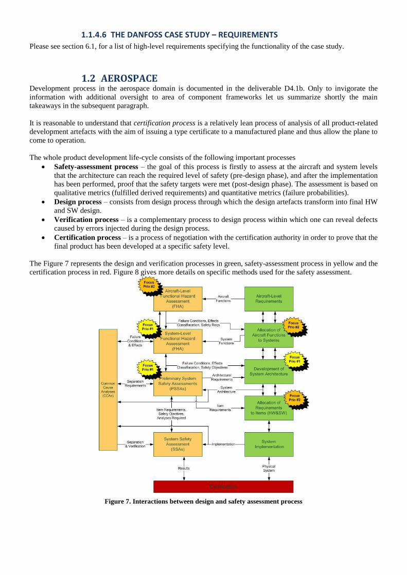
The Figure 7 represents the design and verification processes in green, safety-assessment process in yellow and the
certification process in red. Figure 8 gives more details on specific methods used for the safety assessment.
Figure 7. Interactions between design and safety assessment process

Figure 8. Safety assessment process in aerospace development
1.2.1 APPLICATION SCENARIOS
As the project is focused on avionic safety-critical applications with multi-core processing units we must classify
the scenarios prior to identification of certification obstacles and significant contributors to high cost.
1.2.1.1 SYMMETRIC MULTI-PROCESSING
This scenario resembles the most spread scenario in homes and offices, i.e., MC processor with a single operating
system. Management of the MC processor is solely and entirely on the operating system, thus not affecting either
the user or the designer of applications if not welcome. This approach is generally called symmetric multi-
processing (SMP) as all cores are managed by a single operating system and all cores are equal in term of roles and
utilization.
Main certification obstacles:
Verification of the operating system – it is difficult to prove proper functionality of the operating system
in general (the system is not closed without the running tasks). There are many pitfalls in the multi-core
operating systems, such as shared resource blocking, context-switching of jobs, etc.
Schedulability of the real-time tasks – the tasks are usually very complex and their properties
representing requirements on the scheduling mechanisms are usually difficult to infer; the resulting bounds
are either too pessimistic or difficult to meet. The biggest safety issue is context switching when one job of
the task executes on a different core that a subsequent job of the same task.
Common-cause effect – this is caused by shared physical resources of the processor of different processes
or even systems bringing additional variable into the reliability equation.
1.2.1.2 ASYMMETRIC MULTI-PROCESSING
Since the application of the Integrated Modular Architecture (IMA) solutions in the avionics market, platform
designers have to count with the fact that single silicon will be used by different, mutually non-communicating
applications. In case of IMA, a Processing Board is a single LRU in a rack, which contains several (so far single-
core) processors, which are used by numerous systems.
Solutions with single-core processors were manageable through the time-space partitioning, in short, no two
applications may access the common resource at the same time (handled by TDMA) and no two applications may
access the same memory area (hadled by MMU).

As MC processors have become the state of the art, the LRU vendors have been looking into a way to make use of
them. Asynchronous multi-processing (AMP) seems to be the answer.
Main certification obstacles:
Non-qualified hypervisors – hypervisor, creating virtual partitions, have to guarantee the time and space
partitioning of the MC platform. The approach has not been qualified yet despite the fact that significant
support has been provided by the HW vendors. Obviously this will be tackled once.
Low experience with hierarchical scheduling – shared resources causing blocking, and thus additional
hold times for the affected tasks make it more difficult to reach manage schedulability of the tasks and
processes executing on the same platform. Task competing within a single core have then to compete as a
team representing a single core for the shared resources across cores.
Common-cause effect – this is caused by shared physical resources of the processor of different processes
or even systems bringing additional variable into the reliability equation.
1.2.1.3 TASK-LEVEL PARALLELIZATION
This scenario targets optimal usage of computation resources when executing a highly resource-demanding
application. One could also say that a typical application making use of this scenario is an application which has
been waiting for powerful enough platform to come in order that the algorithm is practically applicable in field.
Examples are signal and image processing algorithms, run-time optimization algorithms, statistical control
applications, etc.
This scenario is applicable either under SMP architecture or the AMP subject that a virtual partition contains more
than one core. Hence, the strengths and weaknesses are inherited with the following modifications.
Main certification obstacles:
Low fidelity in parallel computing temporal and behavioural analysis– verification of the real-time
behaviour in the qualitative sense (deadlocks, synchronisation points, semaphors) is difficult to prove by
testing, major proof of correctness accepted by the certification authorities.
Resource Allocation Scheme – manual resource allocation may be difficult and automated allocation
mechanism are missing.
The component frameworks would definitely be able to provide solutions to many of the obstacles. Identification
of possible solutions will follow immediately after the component frameworks have been analyzed in the
subsequent chapters.
1.2.1.4 SUMMARY OF OBSTACLES
The summary of the obstacles is listed below. Each obstacle is followed by initial thought about their removal
using some functionalities of the component-based frameworks.
Verification of operating systems - the operating systems could be formally modelled and verified on
correctness by some CBFs which allow for this. This would require a powerful CBF able to capture a
closed-form behavioural model of an OS. Moreover, the CBF would have to have a proper verification tool
for this.
Non-qualified hypervisors – this issue relates significantly on the HW providers, such as Freescale or
Intel and can be hardly solved by the CBFs. There is also an assumption that the hypervisor could exist in a
form of a microkernel. In such a case this issue would merge with the first one.
Low practical experience with scheduling and hierarchical scheduling – in this case, component-based
frameworks could help significantly overcome this issue by formally modelling/representing the
algorithms/task properties. Moreover, suitable CBFs would have to be extended to avoid some of the
assumptions under which they operate.
Low fidelity in parallel computing and temporal and behavioural analysis – frameworks capable of
modelling algorithms/tasks in a reasonable way and moreover capable of optimisations of allocation would
help deliver the required performance of dedicated applications based on suitable metrics. Welcome are
design methods used for automated task parallelisation and analysis methods for verification.
Resource allocation scheme – such a CBF could help which allow for modelling of the HW resources and
can provide the allocation (mapping) functionality. Moreover, it would have to be able to model

parallelism of the executed subtasks/algorithms in such a way that allocation could be optimized based on
various criterion (WCET, space, power, etc.)
Common-cause effect – this obstacle relates purely to HW matters and cannot be anyhow solved by the
component frameworks.
In the subsequent chapter, specific remedies to these identified obstacles and the proposed solutions will be
searched for and based on these, proper CBFs will be selected for further development.
1.3 AUTOMOTIVE All SW faults are caused by systematic failures such as, e.g., incorrect and/or incomplete requirements, errors in
design and implementation, insufficient validation and verification. To counter and manage these issues, safety
standards define a qualitative, process-based, approach to define an (A)SIL relative level of rigour required
throughout the SW lifecycle. The primary standard in the automotive industry is ISO-26262.
1.3.1 ISO 26262 –PRODUCT DEVELOPMENT
The development process starts from product conceptualization phase. In this phase analysis of the high level
safety requirements is performed. In the concept phase safety goals are defined to mitigate intolerable risks (i.e.
hazards that have ASILs). Functional Safety Concepts are defined to realise goals. In the product development
phase, safety mechanisms are defined via technical safety concepts to achieve the safety goals. The requirements of
the safety mechanisms are assigned, some to HW some to SW. This section will focus on the software product
development as this is the focus of this work package.
Figure 9. Initial phases of the product development process
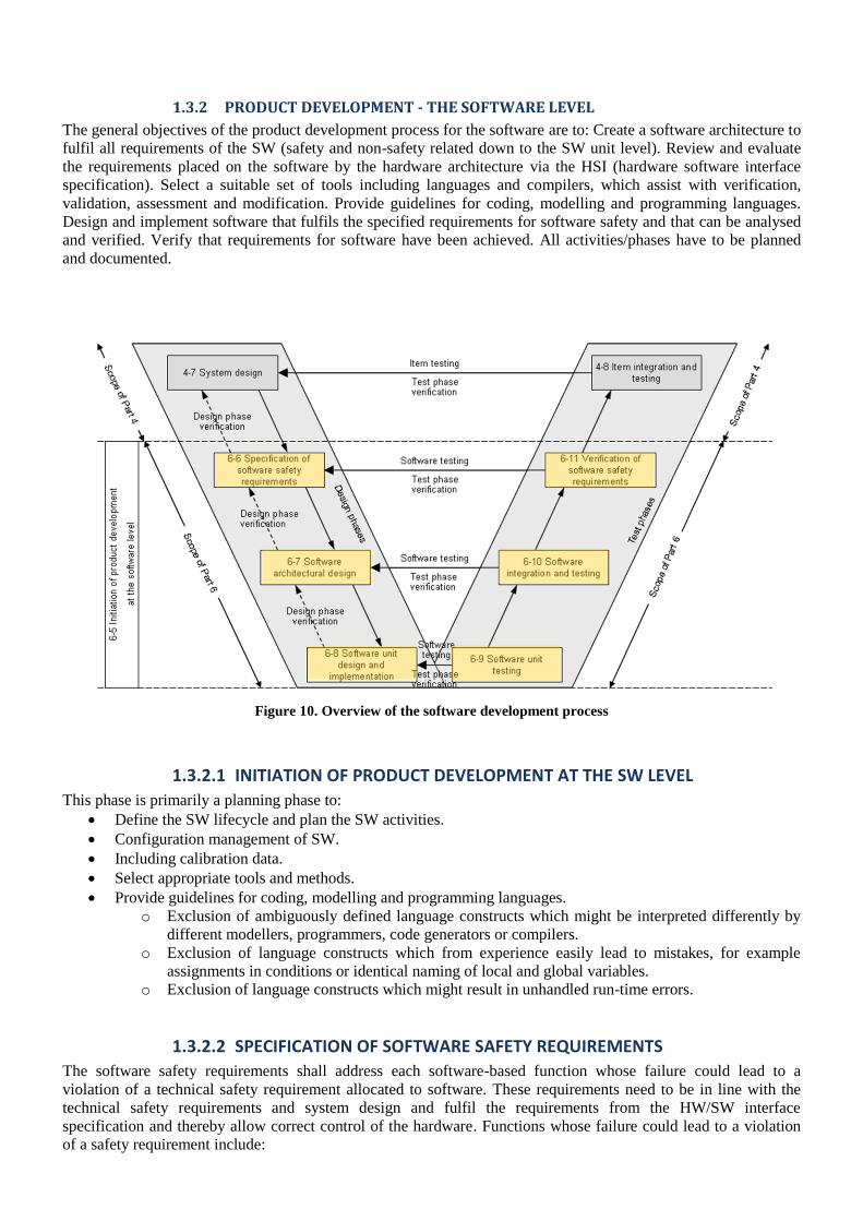
1.3.2 PRODUCT DEVELOPMENT - THE SOFTWARE LEVEL
The general objectives of the product development process for the software are to: Create a software architecture to
fulfil all requirements of the SW (safety and non-safety related down to the SW unit level). Review and evaluate
the requirements placed on the software by the hardware architecture via the HSI (hardware software interface
specification). Select a suitable set of tools including languages and compilers, which assist with verification,
validation, assessment and modification. Provide guidelines for coding, modelling and programming languages.
Design and implement software that fulfils the specified requirements for software safety and that can be analysed
and verified. Verify that requirements for software have been achieved. All activities/phases have to be planned
and documented.
Figure 10. Overview of the software development process
1.3.2.1 INITIATION OF PRODUCT DEVELOPMENT AT THE SW LEVEL
This phase is primarily a planning phase to:
Define the SW lifecycle and plan the SW activities.
Configuration management of SW.
Including calibration data.
Select appropriate tools and methods.
Provide guidelines for coding, modelling and programming languages.
o Exclusion of ambiguously defined language constructs which might be interpreted differently by
different modellers, programmers, code generators or compilers.
o Exclusion of language constructs which from experience easily lead to mistakes, for example
assignments in conditions or identical naming of local and global variables.
o Exclusion of language constructs which might result in unhandled run-time errors.
1.3.2.2 SPECIFICATION OF SOFTWARE SAFETY REQUIREMENTS
The software safety requirements shall address each software-based function whose failure could lead to a
violation of a technical safety requirement allocated to software. These requirements need to be in line with the
technical safety requirements and system design and fulfil the requirements from the HW/SW interface
specification and thereby allow correct control of the hardware. Functions whose failure could lead to a violation
of a safety requirement include:

functions that enable the system to achieve or maintain a safe state;
functions related to the detection, indication and handling of faults of safety-related hardware elements;
functions related to the detection, notification and mitigation of faults in the software itself. These include
both the self-monitoring of the software in the operating system and application-specific self-monitoring of
the software to detect, indicate and handle systematic faults in the application software.
functions related to on-board and off-board tests. On-board tests can be carried out by the system itself or
through other systems within the vehicle network during operation and during the pre-run and post-run
phase of the vehicle. Off-board tests refer to the testing of the safety-related functions or properties during
production or in service.
functions that allow modifications of the software during production and service;
functions with interfaces or interactions with non-safety-related functions;
functions related to performance or time-critical operations; and
functions with interfaces or interactions between software and hardware elements
Interfaces can also include those required for programming, installation, setup, configuration, calibration,
initialisation, start-up, shut down, and other activities occurring in modes other than the "ready to operate"
mode of the embedded software.
The specification of the software safety requirements shall be derived from the technical safety requirements and
the system design (see ISO 26262-4:—, 7.4.1 and ISO 26262-4:—, 7.4.5) and shall consider:
the overall management of safety requirements (see ISO 26262-8:—, Clause 6)
the system and hardware configuration;
Verification of requirements can be carried out using informal verification by walkthroughs (recommended on
ASIL levels A and B), informal verification by inspections, semi-formal verification supported by executable
models (recommended for ASIL A and B and highly recommended by C and D) and formal verification
(recommended for ASIL B, C and D)
1.3.2.3 SOFTWARE ARCHITECTURE DESIGN
The objective in this step is to develop a SW architecture design that represents SW components and their
interactions. In order to develop a single software architectural design both software safety requirements as well as
all non-safety-related requirements have to be fulfilled. Hence, in this sub phase safety-related and non-safety-
related requirements are handled within one development process. The software architectural design has to provide
the means to implement the software safety requirements and to manage the complexity of the technical safety
concept.
Requirements for design notation, and hence tools/methods need to be assessed. Semi-formal notations are
recommended at ASIL A and highly recommended at ASIL B, C, and D. Formal notations are recommended at all
ASIL levels. Informal notations are also recommended for all ASIL levels. The SW architecture design shall
follow principles of modularity, encapsulation and minimum complexity. It shall describe static and dynamic
aspects of the SW components. It is strongly recommended that the software is structured hierarchically and that
the software component size is restricted. The cohesion of components should be high and the coupling low. It
strongly recommended that the architecture ensures appropriate scheduling properties. The software architectural
design shall be developed down to the level where the software units, which are to be treated as indivisible, are
identified.
The software architectural design shall describe both the static design aspects and the dynamic design aspects of
the software components. Static design aspects address:
the software structure including its hierarchical levels;
the logical sequence of data processing;
the data types and their characteristics;
the interfaces of the software components;
the external interfaces of the software; and
the constraints including scope of architecture and external dependencies.
In the case of model-based development, modelling the structure is an inherent part of the overall modelling
activities. Dynamic design aspects then address:
the functionality and behaviour;
the control flow and concurrency of processes;
the data flow between the software components;
the data flow at external interfaces; and
the temporal constraints.
To determine the dynamic behaviour (e.g. of tasks, time slices and interrupts) the different operating states (e.g.
power up, shut down, normal operation, calibration and diagnosis) are considered. To describe the dynamic
behaviour (e.g. of tasks, time slices and interrupts) the communication relationships and their allocation to the
system hardware (e.g. CPU and communication channels) are specified. Every safety-related software component
shall be categorised as one of the following:
newly developed;
reused with modifications;
reused without modifications;
or a COTS product.
Safety analysis (FMEA or FTA) is expected to identify/confirm safety requirements and any dependent failures.
From the safety analysis mechanisms to detect and handle SW errors are then defined. The appropriate measures
for each ASIL can be found in the standard.
The design is verified to show compliance with safety requirements, HW compatibility and that the design has
followed guidelines. Informal verification (by design walkthroughs or inspections) is used to assess whether the
software requirements are completely and correctly refined and realised in the software architectural design. In the
case of model-based development this method can be applied to the model. Semi-formal verification by simulation
of the dynamic part of the model is also recommended. Control and data flow analysis should be carried out.
Formal verification is recommended on ASIL C and D.
1.3.2.4 SOFTWARE UNIT DESIGN AND IMPLEMENTATION
In this phase, for each SW unit, we are focusing on:
Design of both the functional behaviour and internal design.
The implementation which can be automatically generated from the model or as manually written source
code.
The verification of the design and implementation.
The specific requirements for design notation, implementation and rigour of verification are ASIL dependent.
1.3.2.5 SOFTWARE UNIT TESTING
On completion of the SW Unit Implementation we now embark with the testing of the SW units. Testing needs to
be planned, specified, executed and reported. Via the selection of methods, the aim is to demonstrate:
compliance with the software unit design specification;
compliance with the specification of the hardware-software interface;
correct implementation of the functionality;
absence of unintended functionality;
robustness;
sufficiency of the resources to support the functionality;
Targets for coverage shall be defined and measured to evaluate the completeness of test cases. Use of statement
coverage, branch coverage and MC/DC are recommended at all ASIL levels.
1.3.2.6 SOFTWARE INTEGRATION AND TESTING
This phase concerns integration and verification of SW units in to a SW build. For completeness of test cases and
demonstration of no unintended functionally appropriate structural coverage metrics are needed. The standard
advocates function coverage and call coverage. Each function should be called and every function call in the code
should be executed.
1.3.2.7 VERIFICATION OF SW SAFETY REQUIREMENTS
And finally we verify that the embedded SW has met its safety requirements on target HW in the defined target test
environment. This is done using hardware in the loop simulations, test environments (partial integration into the
system), test vehicles. Results are verified to show compliance with expected results and coverage of SW safety
requirements.

1.3.3 ADDITIONAL REQUIREMENTS TO BE CONSIDERED
There are additionally two annexes in the standard that should be considered. SW Configuration. (ISO-26262,
Annex C), which concerns control and verification of configuration data such as:
Valid values: range, scaling, units, interdependencies;
Detection of unintended changes of data.
Freedom from interference by SW partitioning (ISO-26262, Annex D). This is needed to prevent failure
propagation between SW partitions. It allows co-existence of SW partitions that use the same resources with
objective to ensure proper use of CPU, Memory and Communication facilities.
1.3.3.1 QUALIFICATION OF SOFTWARE TOOLS
Qualification of the software tools is needed to provide evidence that a SW tool is suitable for use in developing a
safety related element. The qualification of SW tools must be planned. The use of SW Tool is classified via three
attributes.
1. ―Tool Impact‖ (TI) classification to determine safety impact of SW tool. This represents the impact safety
requirement due to erroneous output of SW tool.
2. ―Tool Error Detection‖ (TD) The probability of detecting erroneous output or malfunction of SW tool.
3. ―Tool confidence level‖ (TCL). TCL = f(TD, TI). There are four TCLs; TCL1 to TCL4. TCL1 represents
no qualification measures, while TCL4 is the most rigorous.
From the TCL rating and associated ASIL, a selection of specific methods are determined by which the SW tool
must be qualified. Examples of methods to qualify a tool are that it has been validated and developed according to
an adequate development process.
1.3.3.2 QUALIFICATION OF SOFTWARE COMPONENTS
To enable reuse of SW components ISO26262 defines a set of criteria to gauge its suitability for use.
Specification
o Requirements; configuration; interfaces; etc.
Verification
o Requirements coverage
o Normal and failure operation.
o Analysis of errors
The result of qualification of SW component needs to be documented and verified.
1.3.3.3 ISO26262 WORK PRODUCTS – SOFTWARE LEVEL
All of the methods/requirements from ISO26262 will require evidence (work product, report etc) to support the
argument for SW safety in the safety case.
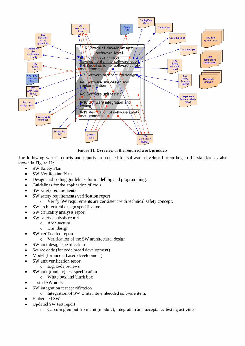
Figure 11. Overview of the required work products
The following work products and reports are needed for software developed according to the standard as also
shown in Figure 11:
SW Safety Plan
SW Verification Plan
Design and coding guidelines for modelling and programming.
Guidelines for the application of tools.
SW safety requirements
SW safety requirements verification report
o Verify SW requirements are consistent with technical safety concept.
SW architectural design specification
SW criticality analysis report.
SW safety analysis report
o Architecture
o Unit design
SW verification report
o Verification of the SW architectural design
SW unit design specifications
Source code (for code based development)
Model (for model based development)
SW unit verification report
o E.g. code reviews
SW unit (module) test specification
o White box and black box
Tested SW units
SW integration test specification
o Integration of SW Units into embedded software item.
Embedded SW
Updated SW test report
o Capturing output from unit (module), integration and acceptance testing activities
1.4 MAIN OBSTACLES FOR CERTIFYING SAFETY-CRITICAL MULTI-CORE PRODUCTS
Based on the information from all three domains, we can now give a summary of main obstacles preventing multi-
core technology adoption in safety- and mixed critical systems or contributing significantly to certification costs.
There are two goals of the projects: 1) enable component-based development of mixed criticality systems on multi-
core platforms, 2) improve cost effectiveness of the development process.
To certify systems running on multi-core platforms two correctness aspects need to be considered: functional
correctness and temporal correctness. From a functional correctness perspective, components need to correctly
implement their specifications and correctly interact with each other. The main challenge on multi-core platforms
is to ensure that components are guaranteed in some manner not to interact with each other in other ways than via
the defined interfaces. This can be guaranteed by either the platform (hardware and/or operating system) or by
verifying (perhaps formally) this property of the components. Also in the presence of NSC components, platform
support to guarantee the integrity of the SC parts is still needed. The tasks running on the platform need to all meet
their timing requirements. This is especially challenging when components share resources. Performing accurate
timing analysis is challenging. Proper isolation support is also needed in the platform to handle NSC components
that might not respect their deadlines.
Cost effectiveness of the development process is an important issue. From a development process point of view,
significant cost savings can be achieved by streamlining the management of the needed information for the
certification authorities. Traceability of information through the development cycle requires significant effort. In
order to effectively use components, they need to carry enough information with them in order to be useful in a
development process for certified safety critical systems. What information is needed is domain specific (standard
specific) and depends on the safety integrate level of the system where the component will be used. Verification
and validation is also a time and resource consuming task. Automated test case generation, other automated
verification techniques and re-use of components could bring savings.
2 OVERVIEW OF CONSTRAINTS IMPOSED BY OTHER WORK PACKAGES
This work package is closely influenced by Work Package 1 (WP1) ―Research Drivers‖ and work package 3
(WP3) ―Trusted Multi-core Platforms‖. The methods and tools in this work package should be applicable for
solving the certification issues identified in Work package 4. In order to make the deliverable more self contained a
short overview of the requirements from WP1 relating to WP2, as well as the platform requirements from WP3 are
given. A separate overview of WP4 ―certification lifecycle issues‖ is not given as those issues have already partly
been given in Section 1 and partly covered by the requirements from WP1.
2.1 WORK PACKAGE 1 REQUIREMENTS
The WP1 requirements for RECOMP, allocates a number of requirements for WP2. An analysis of these
requirements has been carried out to identify requirements that are related to the component based framework and
which specify requirements to be fulfilled by the development tools produced in WP2.
The identified requirements are listed below and are divided into the following groups: Design Progress, Analysis
and Deployment. For more information on the individual requirements, please see WP1 requirements (Baseline 15-
12-2010).
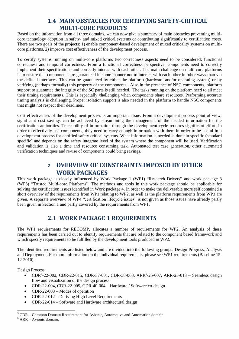
Design Process:
CDR5-22-002, CDR-22-015, CDR-37-001, CDR-38-063, ARR
6-25-007, ARR-25-013 – Seamless design
flow and visualization of the design process
CDR-22-004, CDR-22-005, CDR-40-004 – Hardware / Software co-design
CDR-22-003 – Modes of operation
CDR-22-012 – Deriving High Level Requirements
CDR-22-014 – Software and Hardware architectural design
5 CDR – Common Domain Requirement for Avionic, Automotive and Automation domain.
6 ARR – Avionic domain.

CDR-22-015 – Source code development
CDR-40-005, ARR-25-008 – Validation
CDR-38-059, CDR-38-088 – Design for reusability
CDR-38-004, CDR-19-005, CDR-19-006, ARR-25-017, ARR-25-018, ARR-25-028 – The partitioning of
application/tasks shall be documented
Analysis:
CDR-22-008 – Compatibility checks
CDR-22-009, ARR-25-021 – Timing and resource usage
CDR-22-010, CDR-38-001, CDR-38-002, CDR-38-009, CDR-38-011, CDR-38-012 – Tools for determining
specific configuration parameters: Resource budget, Execution periods and Execution schedules
CDR-22-011 – Analysis to ensure space- and time-partitioning
Deployment:
CDR-22-006, CDR-38-005 – Binding of components to hosts
CDR-22-007 – Simultaneous execution on hardware hosts
The requirements related to design process and methodology requires a seamless design flow from requirements to
the final product, supporting requirement traceability, design of reusable hardware and software components, clear
separation between applications/tasks of different criticality and documentation of the partitioning as well as
verification and validation activities for both hardware and software.
Analysable models of software and hardware are important requirement for the RECOMP participants, ensuring a
seamless integration between different analysis tools of the development platform.
Deployment of software onto hardware hosts is critical, since it is required that the component models enable
representation of software with different criticality.
2.2 OVERVIEW OF WORK PACKAGE 3 The objectives of the work package 3 (WP3) are, according to TA, the following:
Define and develop application independent HW/SW mechanisms for safe multi-core virtualization and
core-to-core communication
Develop different integration methods based on these mechanisms
o From total separation for lowest certification cost to total integration for lowest hardware cost or
minimum power consumption
o From a single safety criticality to a mixture of different criticalities
o Implemented as fully HW, mixed HW/SW to full SW solution
o For different design objectives and constraints
Develop hardware and middleware architecture prototypes
o Supporting a modular certification process
o Using the methods and mechanisms developed in this WP
o For different target architectures, applications and markets
In addition, the safe multi-core architecture to implement should be based on the methodology defined by
workpackage 2 (WP2). For instance, to ensure cost reduction, the designed WP2 mechanisms should help in the
process of modular certification. The components will support different methods to integrate different levels of
criticality, design constraints and objectives. In addition it would be beneficial if the components/methods may be
implemented as a fully hardware, fully software or a mixture of both. It will also be platform, application and
market independent.
To provide a better insight of the WP3 goals and activities, we provide a short description of the five tasks that
have been defined in this workpackage, providing some hints of the constraints and relation between WP2 and
WP3 activities.
2.2.1 TASK 3.1: REQUIREMENTS AND ABSTRACT MECHANISMS FOR VIRTUALI-ZATION AND MONITORING
In the first task, the conflicts that arise when developing a multi-core platform are identified and, then, different
potential solutions are proposed. The major conflicts that have been identified in developing a safe multi-core can

be solved using virtualization mechanisms to ensure compliance with the timing and security assurances. This
should be supported or simplified by tools in WP2. Formal methods as well as scheduling analysis are key
elements required to support the virtualization mechanisms and therefore WP2 methods should align their efforts to
support the WP3 isolation methods.
Run-time monitoring techniques to manage errors that occur and, thus, allowing the transition to fail-safe mode are
the other key elements of task 3.1 In the framework of WP2, task 2.2 deals with on-line validation of components
for certification. This is closely related with the monitoring activities addressed here. So, tasks 3.1 and 2.2 are
related. The results need to be coordinated taking into account that each task is carried out at different levels of
abstraction (high level, functional, for WP2 and low-level, implementation, for WP3).
As final constraint, tasks 2.3 and 2.4 should check the composability issues for the different components and its
relation to virtualization and isolation mechanism described in task 3.1.
2.2.2 TASK 3.2: REQUIREMENTS AND IMPLEMENTATION OF CORE-TO-CORE COM-MUNICATION
The second task addresses the problem of core-to-core communications for safety-critical applications. Core-to-
core communications should be taken into account in the context of virtualization, hypervisors and modularity as
well as inter-device and intra-device device communications. Architectures and mechanisms for such
communications, under the requirements of recertification, will be developed. To address these goals, the existing
architectures will be investigated and, then, new methods will be proposed. The goal is to make an emphasis on
scheduling and arbitration techniques, communication middleware and memory virtualization concepts.
Platforms software and hardware should ensure the isolation of space and time between safety-critical and non-
safety-critical systems, as well as those specified by the Task 3.1. Core-to-core communications typically use
common communications channels and support from one-to-one to, at least, one-to-many connections. The
integrity of the messages and their losses are managed. Also, quality of service mechanisms (minimum latency and
deterministic jitter) required to be implemented, adding individual channel configuration capability.
From the previous description it is clear that core-to-core mechanisms are key element for the system safety
because error on its implementation on incorrect access from the NSC modules could lead to a system failure. As
consequence, carefully design of this stage is mandatory and proper validation of the protocol required. This stage
significantly benefits from the formal techniques described on WP2 that, by construction, allows imposing the
communication protocol correctness. Furthermore, the component models in WP2 should support the core-to-core
communication primitives enabled by WP3.
2.2.3 TASK 3.3: OPERATING SYSTEM SUPPORT FOR SAFE MULTI-CORE INTEG-RATION
The objective of this task is to ensure that operating systems are compatible with the mechanisms developed in the
tasks 3.1 and 3.2, allowing safe integration of multi-core platform. The main implication of this task for WP2
component models and tools is regarding with the schedulability analysis. At the current state of this task, different
OS utilization are possible (PikeOS, RT-Linux, FreeRTOS, OpenRTOS, SafeRTOS, etc..). The tools developed in
WP2 need to be able to analysis these OS in term of schedualbility. The component models should also support
the core-to-core communication facilities offered by these operating systems.
2.2.4 TASK 3.4: HARDWARE SUPPORT FOR OPERATING SYSTEMS, APPLICATIONS AND MONITORING
The goal of this task is to provide hardware support for the techniques developed in tasks 3.1 and 3.2, implemented
on the real hardware architectures which are going to be used by tasks 3.3 and 3.5. This requires the availability of
an executable platform which is mandatory to validate the final system and reduce the simulation times for
verification.
The developed architecture should target a variety of hardware platforms. At the current state of the project, these
are the platforms provided by the RECOMP partners:
Infineon: Platform developed in Virtex-6 FPGA with Infineon soft-core running at 80MHz and multiple
interfaces supported. Target clusters: industrial and automotive.
Camea: AX32 platform. Composed by a single/dual ARM core and small Spartan-6 FPGA for interfacing
electronics. Target cluster: industrial.

Seven Solutions: Virtex-6 FPGA board for avionics and industrial clusters. MCP based on Xilinx
Microblaze and Leon-3 soft-cores. The platform will be provided as open hardware to the community.
In addition, Intel is supposed to provide a platform for validate its Atom processor in the context of safety-critical
systems. TUB provides a firmware based on the Leon-3 processors that currently work on the Synopsys R
HAPSR-62 FPGA prototyping platform.
The relationship between this task and WP2 came from the constraints provided by the integration of mechanism
and tools on the previous tasks. In addition, it is expected that this task have to provide hardware support for some
of the functionalities and components described on WP2. Depending on the target platform, this support could be
required to be done at the software level, moving this constraint to tasks 3.5.
2.2.5 TASK 3.5: HARDWARE AND SOFTWARE COMPONENT INTEGRATION
In this task, the hardware and software components developed in other work packages are composed and bundled
for different applications. Because this is mainly an integration task, it could be required to properly develop
software/middleware to support the components models functionalities described at WP2.
2.2.6 CONCLUSIONS
The WP2 results affect to package WP3 and vice versa. The different constraints imposed for each task are
addressed on the previous notes but they can be summarizes as follows:
The isolation methods and communication channels addressed in tasks 3.1 and 3.2 requires a proper
validation using the tools and methods described in WP2, especially the ones related with formal methods.
Component models should be able to show this isolation and as the same time be able to facilitate the
component reutilization required for reducing cost of re-certification.
Online WP2 component validation should match the run-time monitoring method described in task 3.1 and
it would be very beneficial that WP2 would provide formal (or semiformal) constraints for feeding the
WP3 monitoring functionalities.
The timing analysis provided by WP2 really could help to evaluate the scheduling of the modules running
on the OS described on task 3.3. Therefore, the development of this functionality is highly desirable.
Component models described in WP2 should be capable of implementation on the target platform using
the hardware support described on task 3.4 or the software support base on the operative systems described
in 3.3 task.
As final conclusions, WP2 need to address these issues, trying to maximize the support of the different platform
and OS used on WP3 and developing mechanism that make possible the goals described in WP3.
3 REVIEW OF CURRENT COMPONENT-BASED FRAMEWORKS
We essentially aim to provide a bottom up approach view having an ultimate goal to identify benefits and
disadvantages provided by component-based methodology and frameworks. This chapter is organised as follows:
Section 3.1 contains a survey of state of the art notations and tools for creating and analysing component-based
systems. Section 3.2 then contains a survey of platforms and component frameworks relevant to the project that are
to a large degree language agnostic or do not come with their own analysis framework.
3.1 STATE OF THE ART NOTATIONS AND TOOLS This section describes different tools and notations that can be used for component-based system development.
Each subsection describes a notation or tool. Each section should give an overview of what purpose the notation
can be used for and where each notation can be used in a development process. For each of the notations there is a
description of how component contracts, platform independent models and platform specific models can be
described. Also transformations and consistence checking between the different views are described. Note that
some notations and tools will only support a subset of the views above. The different notations and tools are not
given in any particular order.
Component Contracts. The main idea of contracts is to give an explicit high-level description of components that
can be used for analysis. Contracts can be used to describe several different aspects of components and on several
levels of abstraction.
Functional
Real-time properties
Interactions
In order to be precise about the definition of correctness, some formal definition of semantics of components, as
well as contracts is needed. There should also be some way to check that the component implementation correctly
implements its contract. Furthermore, it should be possible to reason about component interaction based on the
contracts. The analysis should thus be compositional.
Platform independent models. A platform independent model describes the functionality of the system without
considering the platform it will run. Components in these models are often later referred to as system components.
Most notations described here can be used to create platform independent models. The reason for considering
platform independent models is 1) that it enables creation of system models where the system functionality can be
analysed at a high level of abstraction. This enables early detection of design problems. 2) Platform independent
models can be reused for several different platforms. Platform independent models are thus inherently more
reusable.
Platform dependent models. Platform dependent models are obtained from the platform independent models via
model transformations. These model transformations can be automatic, manual or semi-automatic. The
components are here software or hardware components targeted towards a particular platform. Often different non-
functional properties of the system can be optimised by evaluating different mappings of the platform independent
models to platform dependent models.
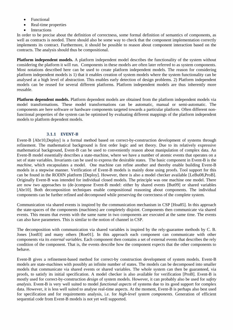
3.1.1 EVENT-B
Event-B [Abr10,Deploy] is a formal method based on correct-by-construction development of systems through
refinement. The mathematical background is first order logic and set theory. Due to its relatively expressive
mathematical background, Event-B can be used to conveniently reason about manipulation of complex data. An
Event-B model essentially describes a state-machine, where we have a number of atomic events that operates on a
set of state variables. Invariants can be used to express the desirable states. The basic component in Event-B is the
machine, which encapsulates a model. One machine can refine another and thereby enable building Event-B
models in a stepwise manner. Verification of Event-B models is mainly done using proofs. Tool support for this
can be found in the RODIN platform [Deploy]. However, there is also a model checker available [LeBu08,ProB].
Originally Event-B was intended for individual closed models. The principle was one machine one model. There
are now two approaches to (de-)compose Event-B model: either by shared events [But09] or shared variables
[Abr10]. Both decomposition techniques enable compositional reasoning about components. The individual
components can be further refined and decomposed while preserving the correctness of the complete system.
Communication via shared events is inspired by the communication mechanism in CSP [Hoa85]. In this approach
the state-spaces of the components (machines) are completely disjoint. Components then communicate via shared
events. This means that events with the same name in two components are executed at the same time. The events
can also have parameters. This is similar to the notion of channel in CSP.
The decomposition with communication via shared variables is inspired by the rely-guarantee methods by C. B.
Jones [Jon83] and many others [Roe01]. In this approach each component can communicate with other
components via its external variables. Each component then contains a set of external events that describes the rely
condition of the component. That is, the events describe how the component expects that the other components to
behave.
Event-B gives a refinement-based method for correct-by construction development of system models. Event-B
models are state-machines with possibly an infinite number of states. The models can be decomposed into smaller
models that communicate via shared events or shared variables. The whole system can then be guaranteed, via
proofs, to satisfy its initial specification. A model checker is also available for verification [ProB]. Event-B is
mostly used for correct-by-construction design of system models. However, it can probably also be used for safety
analysis. Event-B is very well suited to model functional aspects of systems due to its good support for complex
data. However, it is less well suited to analyse real-time aspects. At the moment, Event-B is perhaps also best used
for specification and for requirements analysis, i.e. for high-level system components. Generation of efficient
sequential code from Event-B models is not yet well supported.

References
[Abr10] J.-R. Abrial. Modelling in Event-B: System and Software Engineering, Cambridge University
Press, 2010.
[But09] M. Butler. Decomposition Structures for Event-B. In Integrated Formal Methods iFM2009, LNCS
5423, Springer, 2009.
[Hoa85] C. A. R. Hoare. Communicating Sequential Processes, Prentice Hall International, 1985.
[Jon83] C. B. Jones. Tentative steps toward a development method for interfering programs. Transactions
on Programming Languages and System, 5(4):596-619, 1983.
[LeBu08] M. Leuschel and M. Butler. ProB: An Automated Analysis Toolset for the B Method. Journal
Software Tools for Technology Transfer, 10(2): 185-203, Springer, 2008.
[ProB] M. Leuschel, et. al. ProB: Animator and model checker, 2010, http://www.stups.uni-
duesseldorf.de/ProB
[Roe01] W.-P de Roever, et. al. Concurrency verification: introduction to compositional and
noncompositional methods, Cambridge Univeristy Press, 2001.
3.1.2 THE B-METHOD
The B-method is formal method developed during 1990-ties by J. –R. Abrial [Abr96]. As for Event-B, the
mathematical background is first order logic and set theory. The B-method enables developers to stepwise refine
the system from abstract specification to implementation. Every step can then be proved correct. The components
in B are called machines. A machine corresponds approximately to a static class in C++ or Java. Systems are
developed in a functional decomposition style, where one starts with an abstract description of the main machine
that is then refined. In the refinement the functionality of the machine is decomposed into referenced machines.
When all the machines referenced from the main machine have been refined to only contain implementable
constructs, code can be generated from the machines.
The B-method is intended for systematic, correct-by-construction, development of sequential programs. Thus it
can be used for development of reliable component implementations. The B-method has in itself no notion of
concurrency. Various approaches have been develop parallel and distributed programs in B [WaSe98]. The
approach is basically to consider the programs to consist of atomic actions [BaKu83,BaSe91] that can be executed
in any order if they are enabled. This is similar to Event-B. However, neither classical B nor Event-B has
integrated support for any communication primitives or the notion of threads or processes. This makes them suited
for high-level modelling, but perhaps not directly suited as a refinement-based development process for parallel
code.
The B-method has commercial tool support in the form of Atelier-B [Clearsy], which can generate C, C++ and Ada
code directly from the B-specifications. To do this, the B-models have to conform to a subset of B that is
implementable (referred to as B0). This often involves trivial, but tedious, transformation of the models. To
remedy this problem, a tool is available to automate much of the work in these transformation steps [Clearsy].
According to [BaAm05] this approach makes a complete refinement based development process feasible to
perform for safety-critical systems in an industrial setting. From the point of view of the project where concurrent
systems is of interest, the B-method is insufficient in its original form. It is designed for refinement-based, correct-
by-construction development of sequential programs. However, it can still be used to build individual components.
References
[Abr96] J.-R. Abrial. The B-Book: Assigning Programs to Meanings, Cambridge University Press, 1996.
[BaKu83] R.-J. R. Back and R. Kurki-Suonio. Decentralization of Process Nets with Centralized Control. In
Proceedings of the 2nd ACM SIGACT-SIGOPS Symposium of Principles of Distributed
Computing, 1983.
[BaSe91] R.-J. R. Back and K. Sere. Stepwise Refinement of Action Systems. Structured Programming, 12:
17-30, 1991.
[BaAm05] F. Badeau and A. Amelot. Using B as a High Level Programming Language in an Industrial
Project: Roissy VAL. In 4th International Conference of B and Z Users: ZB2005, LNCS 3455,
Springer, Guildford, UK, 2005.
[BeDeMe98] P. Behm, P. Desforges and J. M. Meynadier. Météor: An Industrial Success in Formal
Development. In B'98: Recent Advances in the Development and Use of the B Method, LNCS
1393, Springer, 1998.
[Clearsy] Clearsy system engineering, Atelier B, 2010, http://www.atelierb.eu/index-en.php

[Deploy] Deploy project, http://www.deploy-project.eu/, 2008-2012
[LeBu08] M. Leuschel and M. Butler. ProB: An Automated Analysis Toolset for the B Method. Journal
Software Tools for Technology Transfer, 10(2): 185-203, Springer, 2008.
[ProB] M. Leuschel, et. al. ProB: Animator and model checker, 2010, http://www.stups.uni-
duesseldorf.de/ProB
[BCore] B-Core Ltd. The B-toolkit. 2002, http://www.b-core.com/btoolkit.html
[WaSe98] M. Waldén and K. Sere. Reasoning About Action Systems Using the B-Method.
Formal Methods in Systems Design, 13, Elsevier, 1998.
3.1.3 SIMULINK AND SYNCHRONOUS DATA FLOW LANGUAGES
Synchronous languages based on the notion of data flow have become popular for design of embedded systems.
Popular languages supported by commercial tools include e.g. SCADE [Est] and Simulink [Math].
Synchronous languages based on data flow have been proposed as an effective approach to design real-time
systems. They provide a provide a convenient way handle logical concurrency in sampled multi-rate systems.
Synchronous data flow languages [LeMe87] are based on the notion of nodes that perform some type of
computation. The nodes can then be connected to other nodes. The information flow over connections between
nodes is always unidirectional. All communication is assumed to take no time and the size of communication
buffers are bounded. Due to these properties is relatively easy to very properties about them and compile them into
efficient sequential code or concurrent code. Furthermore, these languages are designed for development of
sampled, possibly multi-rate systems. These systems are very common in signal-processing and control
application.
This topic is relevant to the project, since many languages based on synchronous data flow are already commonly
used in industry, e.g., Simulink [Math] and SCADE [Est]. Both these tools are also accepted for development of
systems, which are to be certified according to IEC 61508. Furthermore, synchronous languages in general such as
Esterel, Lustre and Signal provide a convenient way to design, analyse and implement reactive real-time systems.
One problem is implementation on distributed systems (in this project on multi-core systems), where it is difficult
to ensure synchronous behaviour. This topic has been studied in e.g. [BCG99,CCMSTN03]. A thorough survey of
implementation techniques for synchronous languages can be found in [BoSi05]. However, implementation on
multi-core systems in a way that is suitable for certification still needs investigation. This is also the case for
separating safety-critical parts from non-safety critical parts.
3.1.3.1 COMPONENT CONTRACTS
The notion of contract (pre- postcondition specification) of programs can be applied to specify functional
properties also of the computational nodes in synchronous data flow languages. This has been done in [MaMo04].
They assign pre- and post-conditions to nodes as well as introduce a way to represent internal state on an abstract
level. Verification of correctness would then entail ensuring that traces generated by the node implementation are
valid according to the contract.
The discrete parts of Simulink can be viewed as a synchronous data flow language. Note that Simulink allows
creation of so-called algebraic loops, which do not fit the synchronous data flow paradigm. However, Simulink
can detect and warn about the cases were these loops can occur. We have developed contracts for Simulink and
methods to compositionally verify Simulink with respect to these contracts [BMW07, Bos08, BGH+10]. The
contracts are similar to the ones in [MaMo04] and they can be used for the synchronous data flow parts of
Simulink. Contracts are not only useful for static verification, but can also be very useful as an aid to document
design decision and partition functionality between components in a systematic way. Furthermore, they are also
useful to describe test cases.
3.1.3.2 PLATFORM INDEPENDENT MODELS
The goal with Simulink is to provide tools for a complete model-driven, model-based, design process.
Consequently, Mathworks provides tools to generate code from the Simulink models, i.e. to map the platform
independent models into platform dependent models. The code generation facilities are provided in the toolboxes
Real-time Workshop and a number of toolboxes that essentially provide extensions to Real-time Workshop [Math].
Multi-rate models can be mapped to either a single task or to several periodic tasks that can be scheduled using
either a third party operating system or something provided by the code generation package. Creation of interrupt-

triggered, asynchronous tasks is also supported. However, scheduling of the tasks on a multi-core or on SMP
systems is not discussed in the data sheets.
The development process and code generation supports certification according to IEC 61508-3 and ISO/DIS
26262-8. A toolbox to help with certification is also provided [Math]. However, the tools need to be used within
the workflows and constraints specified in the certificate of interest. What exactly the limitations are due to these
constraints is not described in detail in the datasheets from Mathworks.
References
[Bos08] P. Bostrom. Formal design and verification of systems using domain-specific languages, Ph. D.
thesis, Åbo Akademi University, Åbo, Finland, 2008
[BMW07] P. Boström and L. Morel and M. Walden. Stepwise development of {Simulink} models using the
refinement calculus framework. In Theoretical Aspects of Computing (ICTAC2007), LNCS 4711,
Springer, 2007
[BGH+10] P. Boström, R. Grönblom, T. Huotari and J. Wiik. An approach to verification of Simulink models,
technical report, Turku Centre for Computer Science, Turku, Finland, 2010.
[Est] Esterel Technologies, SCADE suite, 2010, http://www.esterel-technologies.com
[LeMe87] E. A. Lee and D. G. Messerschmitt. Static Scheduling of Synchronous Data Flow Programs for
Digital Signal Processing. IEEE Transactions on computers, C-36(1), 1987
[Math] Mathworks Inc. Matlab/Simulink, 2010, http://www.mathworks.com/
[MaMo04] F. Maraninchi and L. Morel. Logical-Time Contracts for Reactive Embedded Components, In 30th
EUROMICRO Conference on Component-Based Software Engineering Track, ECBSE'04, Rennes,
France, 2004
3.1.4 AUTOFOCUS 3 (AF3 – TOOL CHAIN)
3.1.4.1 GENERAL ASPECTS OF AF3 CASE TOOL
AutoFOCUS 3 (AF3) is a prototypic research CASE tool for the model-based development of distributed software
systems. It is a powerful tool for modelling, developing and testing on a single surface, thus simplifying the
development workflow.
The following basic aspects are captured by AF3 :
User-oriented functional description of the system
Hierarchical component architecture of the system
Complete behavioural specifications of application parts of the system
Modelling of technical architectures including control units and communication busses and a deployment
logic
Extensible plug-in – structure for further functional extensions (e.g. verification, scheduling, … Compare
section 1.c)
3.1.4.2 GRAPHICAL VIEWS AND NOTATIONS: DESCRIPTION TECHNIQUES OF AF3
AutoFOCUS 3 provides models on different layers of abstractions. Therefore, AF3 provides a set of different
views that enables to specify systems graphically. The following views on a system model are provided: structure
view, behaviour view, interaction view and data type view. In the following we provide a short description of the
different views of AF3. Each one covering different – yet not necessarily disjoint – aspects of the system:
3.1.4.2.1 DATA DEFINITION VIEW
For the specification of user-defined data types and functions AF3 provides DTDs (Data Type Definitions). These
definitions can be expressed using functional syntax. The definition of types, constants and algorithms is done
here. AF3 comes already with a library of type definitions, constructors and functions. AF3 furthermore provides
an evaluation with respect to consistency. All definitions can be commented.
3.1.4.2.2 SYSTEM STRUCTURE VIEW
The System Structure View describes the architecture of a system in terms of components, ports, and channels. In
AF3 a system is a network of components, possibly connected one to the other using ports, communicating via so-
called channels (compare section 3.1.4.4.1). Thus, each communication partner is defined as a component that

sends and receives information via its interface. Each component interface is thereby specified by a set of input and
output ports, respectively. All components of a system are specified via a SSD (System Structure Diagram). Thus,
SSDs are used for describing a high-level architectural decomposition of a system. Thus, the system structure is
defined in a static way, meaning that communication relations are defined at modelling time (e.g. in the domain of
embedded control systems).
3.1.4.2.3 BEHAVIOUR VIEW
The behaviour view captures the behaviour of each atomic component in terms of input / output automata. Thus,
the behaviour of an AF3 component is described by using a STD (State Transition Diagram). It consists of a set of
control states, a set of local and a set of transitions. The given set of local variables build the automaton‘s data
state. The set of transitions describe the component‘s reaction on some input in terms of output and/or state change.
These STDs can be used to model and assigning all behaviour to all components of the given systems.
AF3 can be used to model continuous parts as well as discrete behaviour. While a discrete component performs its
computation (and the corresponding execution of transitions) only once each cycle, a continuous component has no
discretized behaviour. Therefore, additional to the transitions, behaviour for continuous components can be defined
using activities. Activities are assigned to states and are performed continuously (while the guard is satisfied) until
a transition is executed for this state.
Even though different views are mainly orthogonal, there is a natural portion of overlapping that may result in
inconsistent specifications. For detecting inconsistencies between different views, AF3 provides several build in
consistency checks that work on a syntactical basis.
3.1.4.2.3.1 MSCs (Message Sequence Charts)
Message Sequence Charts (MSCs) constitute an abstract representation of communication between processes. This
makes them ideal for depicting the order of messages in the communication between components. The structure of
the Basic Message Sequence Charts is closely related to UML sequence diagrams, but provides a richer syntax.
MSCs will be used in AF3 in order to resemble vertical lifelines of objects (components). MSCs allow a
decomposition of these instances into lifelines of parts of the instance. Furthermore, MSCs allow to structure
messages that are exchanged between the instances with respect to the ordering of messages, e.g. with respect to
the global tick.
3.1.4.3 AF3 – AN EXTENSIBLE TOOL CHAIN
AutoFocus3 is a prototypic research CASE tool that can easily extended by further functionalities. Based on the
generic tooling framework that is build on Eclipse RCP, (basic) AF3 functionality is added (e.g. Type System,
Component Network, Automaton Specification, Hardware Topology, etc.), see Figure 12. New plug-ins for AF3
are continuously developed and integrated in the tool chain, that may be based on / or extend existing functionality.
Figure 12. AF3 – An extensible tool chain
Some examples for AF3 – tool extensions are:
3.1.4.3.1 TEST CASE GENERATION
Model-based testing is a quality assurance activity that can be applied to certain system models in addition to
formal verification methods. Since it is a laborious task to define formal properties, model-based testing enables to
test the intended behaviour of an implementation. Therefore, AF3 provides several functionalities to derive test
cases out of AF3 system models:

On the one hand we enable the generation of test cases out of the test model that is an abstracted model of the
system under test. Furthermore, we provide an effective way of using also the AF3 system model itself for test-
case generation.
3.1.4.3.2 ISABELLE
The Isabelle theorem prover is an interactive theorem-proving framework (a successor of the higher order logic
(HOL) theorem prover). It provides a meta-logic (type theory) that is used to encode object logics, e.g. first-order
logic. AF3 provide inferfaces to use its strong-causal models and transfer them to Isabelle semantics in order to
prove certain system properties.
3.1.4.3.3 CODE GENERATOR
A code generation methodology is provided in AF3 as well. Based on a given deployment (compare section
3.1.4.6.3) AF3 enables to generate Embedded-C-Code for all deployed components given by the logical
architecture. This may include information coming from other extensions (e.g. scheduling).
3.1.4.3.4 MATLAB-SIMULINK / FIBEX IMPORTS
The Simulink tool from MathWorks is the todays de-facto standard tool that is used in the field of model based
development of embedded systems (e.g. in automotive). In order to prove the added value of the modelling and
analysis concepts of the AF3 tool in comparison to the current MBD practice, and to demonstrate the concepts
based on industrial case - studies, AF3 has the functionality to import discrete Simulink models.
FIBEX (Field Bus Exchange Format) is a XML-based format that is widely used in the automotive industry to
describe complex, message – based communication systems. This ASAM standard enables to describe systems
using FlexRay, CAN- or even LIN communications. FIBEX is one major file – exchange standard for tool vendors
in the automotive industry. AF3 has the functionality to import parts of the FIBEX standard.
3.1.4.3.5 SCHEDULING
Scheduling in one of the major topics in system design that guarantees certain system requirements (e.g. timing
properties, bandwidth, etc.). Based on formally defined system model using explicit data-flow and discrete-time
semantics (e.g. AF3 models), we generate precedence graphs and use cutting-edge technologies (e.g. SMT-Solver)
for generating schedules that fulfill certain system requirements.
3.1.4.4 PLATFORM INDEPENDENT MODELS
3.1.4.4.1 LOGICAL ARCHITECTURE
The intention of the logical architecture is to decompose a system into logically distributed sub-systems, namely
components.
3.1.4.4.2 COMPONENTS
The logical architecture of a system is defined by means of logical components communicating via defined
communication paths. Components can be structured in a hierarchic manner, thus forming larger components by
composing smaller ones. A component can therefore be seen as a logical-consistent abstraction of a (sub-) system
that can be refined into further (sub-) components. Whenever decomposition is not possible anymore a component
it is called atomic component. An atomic component consists of an automaton describing its behaviour.
Each component interacts with its environment, meaning input and output relations can specify the component‘s
interfaces. The input / output relations are specified by so-called ports (compare next section). The sender /
receiver relation is defined by channels that connect a sending port with a receiving one.
Figure 13 demonstrates the design concept of a network of components build in AF3. Each component is
graphically drawn as a rectangle. These components exchange messages via ports drawn with small circles (black
ones from output messages and white ones for input ones).
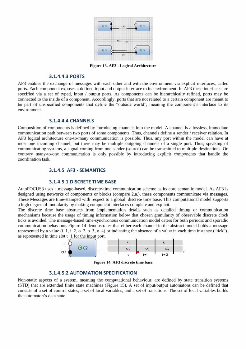
Figure 13. AF3 - Logical Architecture
3.1.4.4.3 PORTS
AF3 enables the exchange of messages with each other and with the environment via explicit interfaces, called
ports. Each component exposes a defined input and output interface to its environment. In AF3 these interfaces are
specified via a set of typed, input / output ports. As components can be hierarchically refined, ports may be
connected to the inside of a component. Accordingly, ports that are not related to a certain component are meant to
be part of unspecified components that define the ―outside world‖, meaning the component‘s interface to its
environment.
3.1.4.4.4 CHANNELS
Composition of components is defined by introducing channels into the model. A channel is a lossless, immediate
communication path between two ports of some components. Thus, channels define a sender / receiver relation. In
AF3 logical architecture one-to-many communication is possible. Thus, any port within the model can have at
most one incoming channel, but there may be multiple outgoing channels of a single port. Thus, speaking of
communicating systems, a signal coming from one sender (source) can be transmitted to multiple destinations. On
contrary many-to-one communication is only possible by introducing explicit components that handle the
coordination task.
3.1.4.5 AF3 - SEMANTICS
3.1.4.5.1 DISCRETE TIME BASE
AutoFOCUS3 uses a message-based, discrete-time communication scheme as its core semantic model. As AF3 is
designed using networks of components or blocks (compare 2.a.), these components communicate via messages.
These Messages are time-stamped with respect to a global, discrete time base. This computational model supports
a high degree of modularity by making component interfaces complete and explicit.
The discrete time base abstracts from implementation details such as detailed timing or communication
mechanisms because the usage of timing information below that chosen granularity of observable discrete clock
ticks is avoided. The message-based time-synchronous communication model caters for both periodic and sporadic
communication behaviour. Figure 14 demonstrates that either each channel in the abstract model holds a message
represented by a value (i_1, i_2, o_2, o_3, o_4) or indicating the absence of a value in each time instance (―tick‖),
as represented in time slot t+1 for the input port.
Figure 14. AF3 discrete time base
3.1.4.5.2 AUTOMATION SPECIFICATION
Non-static aspects of a system, meaning the computational behaviour, are defined by state transition systems
(STD) that are extended finite state machines (Figure 15). A set of input/output automatons can be defined that
consists of a set of control states, a set of local variables, and a set of transitions. The set of local variables builds
the automaton‘s data state.

Figure 15. AF3 - Automaton
The input / output behaviour is specified by the transition properties. Therefore, a transition is complemented with
several annotations: a label, a precondition, input statements, output statements and a post-condition.
Input statements and preconditions can be seen as the guard part of the transition. The guard specifies the necessary
condition for this transition to be fired. Input statements are specified in the format <Port>?<Pattern>, where
<Port> is an input port identifier of the specific component and <Pattern> is a type-correct matching pattern.
Preconditions enable the use of local variables and data state variables to specify the second part of the guard
description. A transition can fire if the precondition holds and the pattern on the input statements match the values
read from the input. Output statements are specified in the format <Port>!<Pattern>, where <Port> is an output
port identifier of the given component and <Pattern> is a type-correct output pattern that may refer to data state
and/or local variables. Post-conditions specify how data state and / or local variables are updated after execution of
the transition.
3.1.4.5.3 STRONG AND WEAK CAUSALITY
AF3 provides different component semantics with respect to timing: the notion of strong and weak causality.
Assuming a global, discrete notion of time, meaning that time advances in discrete logical units and every
component has the exactly same time information of this global time tick, the systems start at the logical time 0 and
all components start synchronously in some initial state. At the beginning of each such computation step, each
atomic component reads its input values and produces the output depending on its specified behaviour (automation
specification).
Strong causality means that the output of each component becomes visible to the specified communication partner
(another component or the environment) at the beginning of the next global tick. This delay of one logical time unit
is meant by the strong causality assumption. Weak causality means that instantaneous reaction on a given input
without a time delay of one global tick. The current output may therefore depend on the current input.
3.1.4.6 PLATFORM DEPENDENT MODELS
AF3 provides platform dependent models that are called technical architecture (TA). They describe a hardware
topology that is composed of hardware components, which in turn may consist of hardware ports (sensors or
actuators) and busses. In the context of RECOMP, fortiss GmbH extended the technical architecture by a multi-
core hardware meta-model (compare section 3.1.4.6.2). This enables AF3 to describe various kinds of multi-core
platforms used in RECOMP project partners for the investigation of further questions, especially related to (re-)
certification of safety-critical systems that run on multi-core platforms.
3.1.4.6.1 HARDWARE MULTI-CORE META-MODEL
The proposed AF3 hardware Meta-Model (Figure 16), related to a given multi-core platform looks like this:
1. The Hardware Meta-Model bases on 3 basic classes, namely, HComponent, Port and Interface.
2. HComponent represents the basic element used to build up the mulitcore platform.
3. Port and Interface used to define how the basic elements are connected together.
4. HierachicalComponent is a container which can contain HComponent.
5. PE, Memory,Pheripheral, CommunicationFacility, ArbitrationScheme and HierchicalComponent are
HComponent in current Metamodel(it can be extended).
6. AvalonPort and AvalonInterface are the Port and Interface defined in the current Metamodel respectively.
7. AvalonMasterPort and AvalonSlavePort are the AvalonPort in current Metamodel.
8. AvalonMasterInterface and AvalonSlaveInterface are the AvalonInterface in current Metamodel.
9. PE, Memory,Pheripheral have Port.
10. CommunicationFacility has Interface.
11. Both PE and CommunicationFacility can have ArbitrationScheme.

12. TDMA, RoundRobin and StaticPriority are the ArbitrationScheme in current Metamodel.
13. Bus, P2PConnection and NoC are the CommunicationFacility in current Metamodel.
Figure 16. AF3 hardware Meta-Model
3.1.4.6.2 FIRST MC-PLATFORM MODEL
In a first step we focus on the Altera Multi-core Platform (Cyclone III development board), see Figure 17. A short
description of this platform is given below:
1. It has 3 PEs and 1 shared memory connected by 1 avalonbus.
2. Each PE has one private memory that is connected with the PE using p2pconnection.
3. The avalonbus has a roundrobin arbitration scheme.
4. Each PE has 2 ports with 1 port connected with avalonbus and the one avalonport connected with
p2pconnection.
5. Each private memory has 1 port connected with the p2pconnection.
6. The shared memory has 1 port connected with avalonbus.
7. The avalonbus has 4 interfaces, 1 interface connected to shared memory and each of the other 3
interfaces connected to one PE.
8. Each p2pconnection has 2 interfaces, 1 interface connected to private memory and the other interface
connected to PE.
Figure 17. Schematic Model of the Altera Multi-core Platform

Figure 18. AutoFOCUS3 Altera Model
3.1.4.6.3 DEPLOYMENT / MAPPING
AF3 provides a clear distinction between the logical and the technical architecture. The logical architecture
provides a complete description of the system functionality, however, without anticipating technical decisions with
respect to implementation details, whereas the hardware layer provides models of the hardware on which the
application logic has to run. The main advantage of a clear distancing between the logical and the technical
architecture is that it enables a flexible (re-) deployment of the logical components to a distributed network of
communication resources (either ECUs or cores of a multi-core platform).
Figure 19. Deployment Metamodel
A possible deployment metamodel may be structured as depicted in Figure 19. The deployment connects the
logical architecture with the hardware / technical architecture and provides a so-called, mapping. This will be done
for the presented platform-dependent metamodel in section 3.a.
Figure 20. From logical to technical architecture

This deployment logic is then used to map components from the logical to the technical architecture as depicted in
Figure 20. Component C0 is deployed on processing element PE1, C1 to PE2, …. Also message – based
communication, represented by the channels of the logical architecture are deployed on an bus connecting different
processing elements (e.g. the Avalon bus)
3.1.4.7 SYNTHESIS TECHNIQUES - COMPONENT CONTRACTS
Based on a formally defined system model using explicit data-flow and discrete-time semantics (e.g. AF3 models)
and a hardware multi-core metamodel, we develop semi-automatic design space exploration methods and trade-off
analyses that will decide the deployment of functions (components) on mixed-criticality systems. A mapping will
be done such that partitioning and resource constraints are satisfied. Therefore, based on the logical and technical
architecture of an AF3 model, we are able to abstract a precedence graphs that is used for scheduling synthesis.
The logical architecture provides a set of components that, in general, represents a set of tasks and a set of channels
that represent messages of a given precedence graph. Using these information, we generate a precedence graph G
as a set of tasks T = {t0; t1; t2; … } and a set of messages M = {m0;m1;m2; … }. Furthermore, the precedence
relations are as well. In WP2 , task 2.4 Configuration synthesis to support certification and upgrade of NSC part,
Fortiss investigates the deployment of components and its impact on certification. Synthesis tools will generate
configuration parameters such that separation is guaranteed, in terms of functionality, fault-containment and
timing. Fortiss will develop semi-automatic design space exploration methods and trade-off analyses that will
decide the deployment of functions on mixed-criticality systems.
3.1.5 AADL (ARCHITECTURE ANALYSIS AND DESIGN LANGUAGE)
Defined in the Society of Automotive Engineers (SAE) standard AS5506 [SAE06a], AADL is designed to model
embedded, real-time systems such as avionics systems or automotive control systems. Such systems are usually
composed of complex distinct subsystems - both hardware and software elements - exhibiting frequent
intercommunication. As each component might be designed by various engineers under different perspectives,
integrating different complex components can be nontrivial due to lack of unified view of the whole system.
Hence, AADL's design purpose is to support the possibility of integrating different system implementations.
AADL allows engineers to view the systems as an assembly of components which can be either software ,
hardware or a composite (components that can contain both software and hardware). AADL also permits mapping
software onto computational hardware elements. In order to analyze the interoperability between components,
many syntaxes and semantics are provided in AADL standard to define interactions between components, or in
other words, runtime behaviours. First, components communicate exclusively through well-defined interfaces.
Then runtime mechanisms of exchanging data can be defined by using runtime semantics such as message passing
or event passing. Furthermore, AADL also provides support for dynamic reconfiguration of runtime architecture
by introducing operational modes and mode transitions. By supporting runtime behaviour modelling, system
modelled in AADL can be used to predict and analyze non-functional system requirements such as reliability,
availability and timing.
Even though many requirements mentioned above can be examined by modelling systems in AADL, the language
can still be extended to offer more analytical requirements which the core AADL standard does not support. There
are two types of extension mechanisms in AADL: extension by adding an annex or by defining a new property set.
Annex is an extension construct used to add specialized description elements into the core of AADL. This
sublanguage is meant to meet domain- or project-specific requirements which the core AADL syntax and
semantics cannot fulfill. For example, Error Model Annex [SAE06b] and Behaviour Annex [SAE11] are two
standardized extensions to the core AADL standard. The former is used to model potential errors in the system
while the latter enables formal verification using model checking by modelling systems with functional behaviours.
Another extension mechanism in AADL standard is by declaring a new property set. New properties can be used
separately to enrich the core AADL standard or inclusively with another AADL annex.
As described earlier, AADL is not meant to specify the functional structure of the software implementation or
detailed architecture of hardware components. In fact, AADL focuses on modelling runtime architecture where
implementations of software and hardware functionalities are abstracted away. Hence, in order to achieve full
description, AADL can be used in conjunction with other existing modelling languages. For example, in software
modelling aspect, AADL and UML (Unified Modelling Language) [OMG07] can be complementary as UML can
be used to model the functional structure of software implementation – the ability which AADL cannot offer. On
the other side, in addition to using AADL to model interfaces and properties of execution platform components,
detailed hardware implementation can be described using VHDL (Very High Speed IC Hardware Description
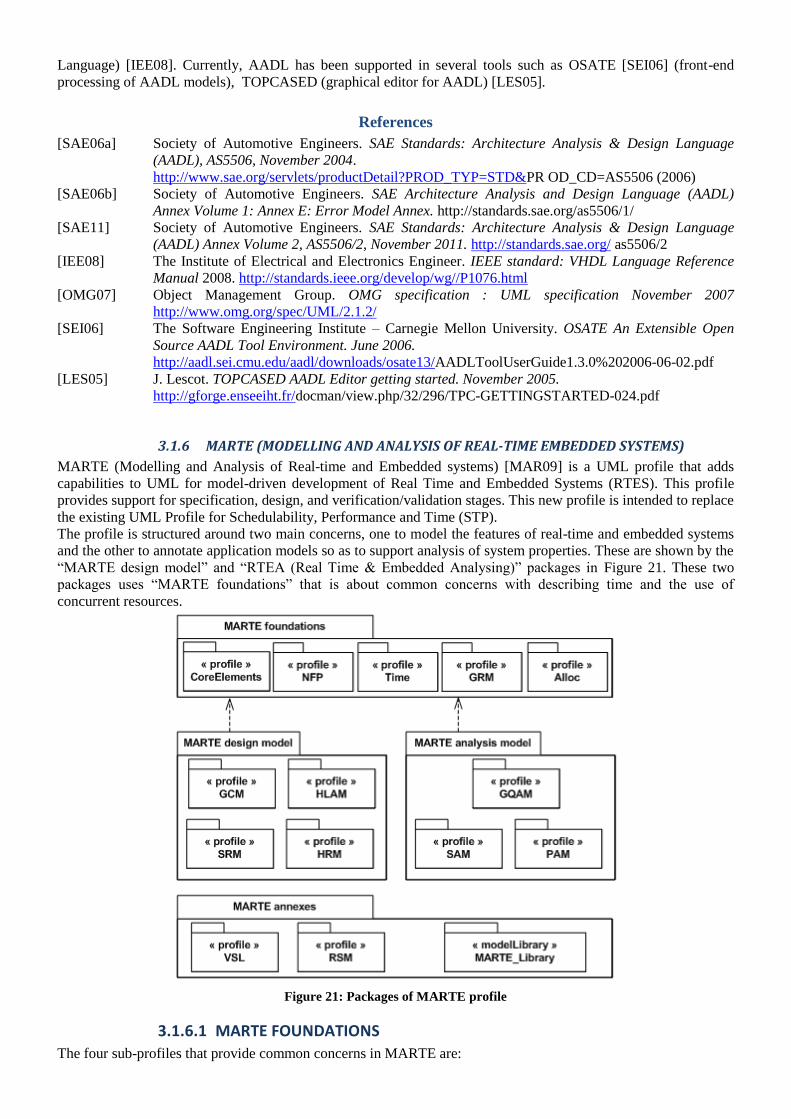
Language) [IEE08]. Currently, AADL has been supported in several tools such as OSATE [SEI06] (front-end
processing of AADL models), TOPCASED (graphical editor for AADL) [LES05].
References
[SAE06a] Society of Automotive Engineers. SAE Standards: Architecture Analysis & Design Language
(AADL), AS5506, November 2004.
http://www.sae.org/servlets/productDetail?PROD_TYP=STD&PR OD_CD=AS5506 (2006)
[SAE06b] Society of Automotive Engineers. SAE Architecture Analysis and Design Language (AADL)
Annex Volume 1: Annex E: Error Model Annex. http://standards.sae.org/as5506/1/
[SAE11] Society of Automotive Engineers. SAE Standards: Architecture Analysis & Design Language
(AADL) Annex Volume 2, AS5506/2, November 2011. http://standards.sae.org/ as5506/2
[IEE08] The Institute of Electrical and Electronics Engineer. IEEE standard: VHDL Language Reference
Manual 2008. http://standards.ieee.org/develop/wg//P1076.html
[OMG07] Object Management Group. OMG specification : UML specification November 2007
http://www.omg.org/spec/UML/2.1.2/
[SEI06] The Software Engineering Institute – Carnegie Mellon University. OSATE An Extensible Open
Source AADL Tool Environment. June 2006.
http://aadl.sei.cmu.edu/aadl/downloads/osate13/AADLToolUserGuide1.3.0%202006-06-02.pdf
[LES05] J. Lescot. TOPCASED AADL Editor getting started. November 2005.
http://gforge.enseeiht.fr/docman/view.php/32/296/TPC-GETTINGSTARTED-024.pdf
3.1.6 MARTE (MODELLING AND ANALYSIS OF REAL-TIME EMBEDDED SYSTEMS)
MARTE (Modelling and Analysis of Real-time and Embedded systems) [MAR09] is a UML profile that adds
capabilities to UML for model-driven development of Real Time and Embedded Systems (RTES). This profile
provides support for specification, design, and verification/validation stages. This new profile is intended to replace
the existing UML Profile for Schedulability, Performance and Time (STP).
The profile is structured around two main concerns, one to model the features of real-time and embedded systems
and the other to annotate application models so as to support analysis of system properties. These are shown by the
―MARTE design model‖ and ―RTEA (Real Time & Embedded Analysing)‖ packages in Figure 21. These two
packages uses ―MARTE foundations‖ that is about common concerns with describing time and the use of
concurrent resources.
Figure 21: Packages of MARTE profile
3.1.6.1 MARTE FOUNDATIONS
The four sub-profiles that provide common concerns in MARTE are:
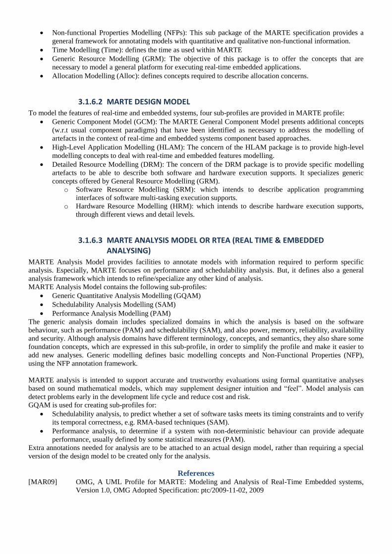
Non-functional Properties Modelling (NFPs): This sub package of the MARTE specification provides a
general framework for annotating models with quantitative and qualitative non-functional information.
Time Modelling (Time): defines the time as used within MARTE
Generic Resource Modelling (GRM): The objective of this package is to offer the concepts that are
necessary to model a general platform for executing real-time embedded applications.
Allocation Modelling (Alloc): defines concepts required to describe allocation concerns.
3.1.6.2 MARTE DESIGN MODEL
To model the features of real-time and embedded systems, four sub-profiles are provided in MARTE profile:
Generic Component Model (GCM): The MARTE General Component Model presents additional concepts
(w.r.t usual component paradigms) that have been identified as necessary to address the modelling of
artefacts in the context of real-time and embedded systems component based approaches.
High-Level Application Modelling (HLAM): The concern of the HLAM package is to provide high-level
modelling concepts to deal with real-time and embedded features modelling.
Detailed Resource Modelling (DRM): The concern of the DRM package is to provide specific modelling
artefacts to be able to describe both software and hardware execution supports. It specializes generic
concepts offered by General Resource Modelling (GRM).
o Software Resource Modelling (SRM): which intends to describe application programming
interfaces of software multi-tasking execution supports.
o Hardware Resource Modelling (HRM): which intends to describe hardware execution supports,
through different views and detail levels.
3.1.6.3 MARTE ANALYSIS MODEL OR RTEA (REAL TIME & EMBEDDED ANALYSING)
MARTE Analysis Model provides facilities to annotate models with information required to perform specific
analysis. Especially, MARTE focuses on performance and schedulability analysis. But, it defines also a general
analysis framework which intends to refine/specialize any other kind of analysis.
MARTE Analysis Model contains the following sub-profiles:
Generic Quantitative Analysis Modelling (GQAM)
Schedulability Analysis Modelling (SAM)
Performance Analysis Modelling (PAM)
The generic analysis domain includes specialized domains in which the analysis is based on the software
behaviour, such as performance (PAM) and schedulability (SAM), and also power, memory, reliability, availability
and security. Although analysis domains have different terminology, concepts, and semantics, they also share some
foundation concepts, which are expressed in this sub-profile, in order to simplify the profile and make it easier to
add new analyses. Generic modelling defines basic modelling concepts and Non-Functional Properties (NFP),
using the NFP annotation framework.
MARTE analysis is intended to support accurate and trustworthy evaluations using formal quantitative analyses
based on sound mathematical models, which may supplement designer intuition and ―feel‖. Model analysis can
detect problems early in the development life cycle and reduce cost and risk.
GQAM is used for creating sub-profiles for:
Schedulability analysis, to predict whether a set of software tasks meets its timing constraints and to verify
its temporal correctness, e.g. RMA-based techniques (SAM).
Performance analysis, to determine if a system with non-deterministic behaviour can provide adequate
performance, usually defined by some statistical measures (PAM).
Extra annotations needed for analysis are to be attached to an actual design model, rather than requiring a special
version of the design model to be created only for the analysis.
References
[MAR09] OMG, A UML Profile for MARTE: Modeling and Analysis of Real-Time Embedded systems,
Version 1.0, OMG Adopted Specification: ptc/2009-11-02, 2009
3.1.7 PROGRAMMABLE DIGITAL CIRCUITS
A programmable digital circuit is a silicon chip device containing some basic configurable logic blocks. Unlike an
Application Specific Integrated Circuit (ASIC) which can perform a single specific function for the lifetime of the
chip these devices can be reprogrammed in order to perform a different function in a matter of microseconds.
Before it is programmed a device knows nothing about how to communicate with the devices surrounding it. This
is both a blessing and a curse as it allows a great deal of flexibility while greatly increasing the complexity of
programming it. The ability to reprogram theses devices has led them to be widely used by hardware designers for
prototyping circuits. A typical nowadays example of programmable digital circuits used in embedded applications
is the Field Programmable Gate Array – FPGA [SaSc10]. There are also some older programmable digital circuits
like Programmable logic (PAL), Simple or Complex Programmable Gate Arrays (SPLD, CPLD), etc. However, at
the moment the most complex programmable digital circuits are FPGA devices [Jai10]. The internal structure of
these devices contain array of configurable blocks. More details can be found in [Kar05].
When FPGAs first arrived on the scene in the mid of 1980s [Max04], they were largely used to implement the
interface between larger logical blocks, functions or devices (so-called glue logic), medium complexity state
machines or relatively limited data processing tasks. During the early 1990s, as the size and sophistication of
FPGAs started to increase, their big markets at that time were in the telecommunications and networking areas,
both of which involved processing large blocks of data. Later (by the end of 1990s), the use of FPGAs in
consumer, automotive and industrial application underwent a huge boom. FPGAs are often used to prototype
ASIC or to provide a hardware platform for the purpose of verification the physical implementation of new
algorithms. By the early 2000s, high-performance FPGAs containing millions of gates become available. Some of
these devices also include features like memories, embedded microprocessor cores, high speed input/output
interfaces, etc. The end result is that today‘s FPGAs can be used for implementing almost anything including
communication devices, radar, image and other digital signal processing (DSP) applications; all the way to system-
on-chip (SoC) components that contain both hardware and software elements.
3.1.7.1 CIRCUITS DESCRIPTION FOR FPGA
The basic level for FPGA design entry is register transfer level (RTL) which represents a digital circuit as a set of
connected primitives (adders, counters, multiplexers, registers etc.). There are two basic ways to create a RTL
design: schematic entry and hardware description language or simply HDL entry. Schematic entry is somewhat
close to netlist. Netlists describe the connectivity of an electronic design and usually convey connectivity
information and provide nothing more than instances, nets, and also some attributes. But, it is not very convenient
to use for large projects. HDL entry is more convenient, but needs an additional program (synthesizer) in order to
translate HDL description to netlist.
3.1.7.2 HARDWARE DESCRIPTION LANGUAGE
A hardware description language (HDL) is a language from a class of computer languages or programming
languages for formal description of digital circuits. It can describe the circuit's operation, its design and
organization, and tests to verify its operation by means of simulation. There are two aspects of modelling digital
circuit that any HDL facilitates [Lim09]; true abstract behaviour or hardware structure.
Behavioural description (Figure 22) exploits the fact that digital circuit behaviour can be modelled by an
algorithm. Obviously, there are used standard constructions well known from traditional programming languages –
like C, but updated to describing hardware properly. Behavioural based HDL includes loops (for, do, while …),
procedures, functions etc. Naturally, some features of traditional programming languages are not supported, e.g.
a recursion. Moreover, behavioural description does not care about circuit details, because it is completely in
competence of other electronic design automation (EDA) tools in a specific tool chain.
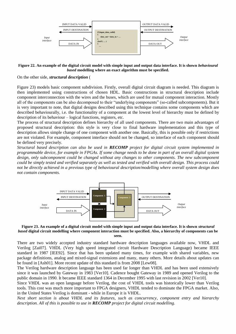
Figure 22. An example of the digital circuit model with simple input and output data interface. It is shown behavioural
based modelling where an exact algorithm must be specified.
On the other side, structural description (
Figure 23) models basic component subdivision. Firstly, overall digital circuit diagram is needed. This diagram is
then implemented using constructions of chosen HDL. Basic constructions in structural description include
component interconnection with the wires and the buses, which are used for mutual component interaction. Mostly
all of the components can be also decomposed to their ―underlying components‖ (so-called subcomponents). But it
is very important to note, that digital designs described using this technique contains some components which are
described behaviourally, i.e. the functionality of a component at the lowest level of hierarchy must be defined by
description of its behaviour – logical functions, registers, etc.
The process of structural description defines hierarchy of all used components. There are two main advantages of
proposed structural description: this style is very close to final hardware implementation and this type of
description allows simple change of one component with another one. Basically, this is possible only if restrictions
are not violated. For example, component interface should not be changed, so interface of each component should
be defined very precisely.
Structural based description can also be used in RECOMP project for digital circuit system implemented in
programmable device, for example in FPGAs. If some change needs to be done in part of an overall digital system
design, only subcomponent could be changed without any changes to other components. The new subcomponent
could be simply tested and verified separately as well as tested and verified with overall design. This process could
not be directly achieved in a previous type of behavioural description/modelling where overall system design does
not contain components.
Figure 23. An example of a digital circuit model with simple input and output data interface. It is shown structural
based digital circuit modelling where component interaction must be specified. Also, a hierarchy of components can be
seen.
There are two widely accepted industry standard hardware description languages available now, VHDL and
Verilog [Zai07]. VHDL (Very high speed integrated circuit Hardware Description Language) became IEEE
standard in 1987 [IEE92]. Since that has been updated many times, for example with shared variables, new
package definitions, analog and mixed-signal extensions and many, many others. More details about updates can
be found in [Ash01]. More recent update of this standard is from 2008 [Lew08].
The Verilog hardware description language has been used far longer than VHDL and has been used extensively
since it was launched by Gateway in 1983 [Ver10]. Cadence bought Gateway in 1989 and opened Verilog to the
public domain in 1990. It became IEEE standard 1364 in December 1995 with last revision in 2002 [Ver10].
Since VHDL was an open language before Verilog, the cost of VHDL tools was historically lower than Verilog
tools. This cost was much more important to FPGA designers, VHDL tended to dominate the FPGA market. Also,
in the United States Verilog is dominant - while in Europe it is VHDL.
Next short section is about VHDL and its features, such as concurrency, component entry and hierarchy
description. All of this is possible to use in RECOMP project for digital circuit modelling.
An Algorithm
Input
interface
INPUT DATA VALID
INPUT DESTINATION
READY
DATA IN
Output
interface
OUTPUT DATA VALID
OUTPUT DESTINATION
READY
DATA OUT
if (input_data_valid)
{
data_out = data_in + …
}
elseif ( … )
{
…
Input
interface
INPUT DATA VALID
INPUT DESTINATION
READY
DATA IN
Output
interface
OUTPUT DESTINATION
READY
DATA OUT
Component 1
Component 2
Component 4
Component 3

3.1.7.3 VHDL
3.1.7.3.1 STRUCTURE AND HIERARCHY
Basic component in VHDL can be described as it is shown in Example 1 below. It is possible to define input,
output or inout ports of component with various types (in our case predefined VHDL type bit) and lengths (single
bit vs. wide busses) and also eventually predefine generic constants on the interface (not listed in our Example 1).
Each component (or entity in parlance of VHDL) should have defined its own architecture which is described
between keywords begin and end. Furthermore, a several different architectures can be specified and these are
distinguished with special keyword (in our case only single architecture: arch1).
entity test is
port ( A : out bit; B : out bit;
C : in bit; D : in bit; E : in bit
);
architecture arch1 of test is
begin
…
end architecture arch1;
Example 1
Example 1: Example of a simple component in VHDL.
Architecture of each component can be described with statements, described below in next section, or with
instantiation of other subcomponents. This is shown in Example 2.
architecture arch1 of test is
begin
u1: entity work.subtest (arch1) port map (i1, o2);
u2: entity work.subtest2 (arch1) port map (i2, i3, o2);
u3: entity work.subtest3 (arch2) port map (i1, i2, o1);
…
end architecture arch1;
Example 2
Example 2: Interconnection with other subcomponents in VHDL.
With this component interconnection the defined hierarchy of components is defined implicitly, as shown in Figure
23.
3.1.7.3.2 CONCURRENCY
VHDL has totally different sets of statements for the sequential and concurrent parts of the program. Sequential
blocks, which are out of scope of this document, and their description can be found in [Zai07] and [Lim09], are
needed in some cases when the description of complicated operations is necessary. On the other hand, concurrent
behaviour is traditional in electronic circuit, because all components are running and process data in parallel.
Therefore, all statements are considered to be concurrent.
A <= B or C;
B <= D and (not E);
Example 3: Concurrent statements in VHDL. A, B, C, D and E are previously defined ports.
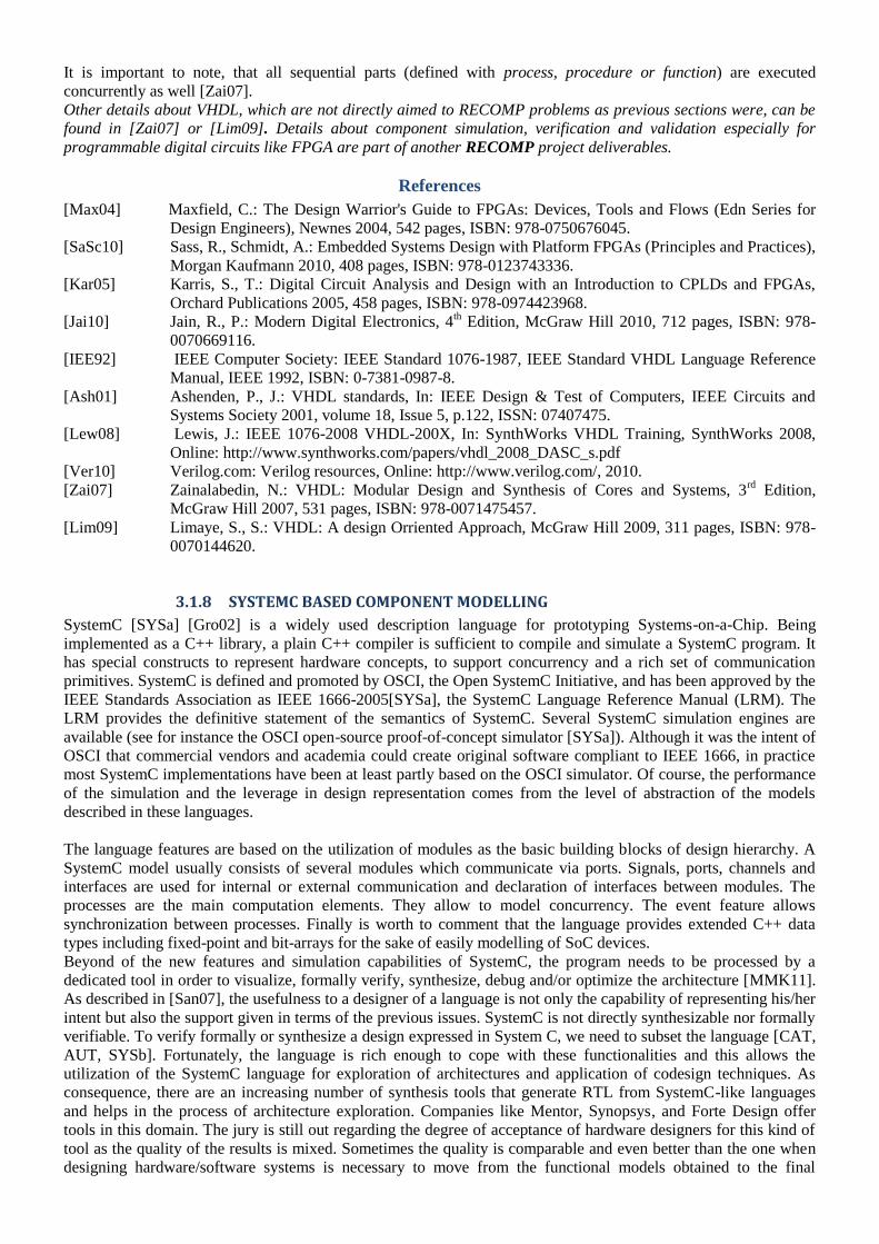
It is important to note, that all sequential parts (defined with process, procedure or function) are executed
concurrently as well [Zai07].
Other details about VHDL, which are not directly aimed to RECOMP problems as previous sections were, can be
found in [Zai07] or [Lim09]. Details about component simulation, verification and validation especially for
programmable digital circuits like FPGA are part of another RECOMP project deliverables.
References
[Max04] Maxfield, C.: The Design Warrior's Guide to FPGAs: Devices, Tools and Flows (Edn Series for
Design Engineers), Newnes 2004, 542 pages, ISBN: 978-0750676045.
[SaSc10] Sass, R., Schmidt, A.: Embedded Systems Design with Platform FPGAs (Principles and Practices),
Morgan Kaufmann 2010, 408 pages, ISBN: 978-0123743336.
[Kar05] Karris, S., T.: Digital Circuit Analysis and Design with an Introduction to CPLDs and FPGAs,
Orchard Publications 2005, 458 pages, ISBN: 978-0974423968.
[Jai10] Jain, R., P.: Modern Digital Electronics, 4th Edition, McGraw Hill 2010, 712 pages, ISBN: 978-
0070669116.
[IEE92] IEEE Computer Society: IEEE Standard 1076-1987, IEEE Standard VHDL Language Reference
Manual, IEEE 1992, ISBN: 0-7381-0987-8.
[Ash01] Ashenden, P., J.: VHDL standards, In: IEEE Design & Test of Computers, IEEE Circuits and
Systems Society 2001, volume 18, Issue 5, p.122, ISSN: 07407475.
[Lew08] Lewis, J.: IEEE 1076-2008 VHDL-200X, In: SynthWorks VHDL Training, SynthWorks 2008,
Online: http://www.synthworks.com/papers/vhdl_2008_DASC_s.pdf
[Ver10] Verilog.com: Verilog resources, Online: http://www.verilog.com/, 2010.
[Zai07] Zainalabedin, N.: VHDL: Modular Design and Synthesis of Cores and Systems, 3rd
Edition,
McGraw Hill 2007, 531 pages, ISBN: 978-0071475457.
[Lim09] Limaye, S., S.: VHDL: A design Orriented Approach, McGraw Hill 2009, 311 pages, ISBN: 978-
0070144620.
3.1.8 SYSTEMC BASED COMPONENT MODELLING
SystemC [SYSa] [Gro02] is a widely used description language for prototyping Systems-on-a-Chip. Being
implemented as a C++ library, a plain C++ compiler is sufficient to compile and simulate a SystemC program. It
has special constructs to represent hardware concepts, to support concurrency and a rich set of communication
primitives. SystemC is defined and promoted by OSCI, the Open SystemC Initiative, and has been approved by the
IEEE Standards Association as IEEE 1666-2005[SYSa], the SystemC Language Reference Manual (LRM). The
LRM provides the definitive statement of the semantics of SystemC. Several SystemC simulation engines are
available (see for instance the OSCI open-source proof-of-concept simulator [SYSa]). Although it was the intent of
OSCI that commercial vendors and academia could create original software compliant to IEEE 1666, in practice
most SystemC implementations have been at least partly based on the OSCI simulator. Of course, the performance
of the simulation and the leverage in design representation comes from the level of abstraction of the models
described in these languages.
The language features are based on the utilization of modules as the basic building blocks of design hierarchy. A
SystemC model usually consists of several modules which communicate via ports. Signals, ports, channels and
interfaces are used for internal or external communication and declaration of interfaces between modules. The
processes are the main computation elements. They allow to model concurrency. The event feature allows
synchronization between processes. Finally is worth to comment that the language provides extended C++ data
types including fixed-point and bit-arrays for the sake of easily modelling of SoC devices.
Beyond of the new features and simulation capabilities of SystemC, the program needs to be processed by a
dedicated tool in order to visualize, formally verify, synthesize, debug and/or optimize the architecture [MMK11].
As described in [San07], the usefulness to a designer of a language is not only the capability of representing his/her
intent but also the support given in terms of the previous issues. SystemC is not directly synthesizable nor formally
verifiable. To verify formally or synthesize a design expressed in System C, we need to subset the language [CAT,
AUT, SYSb]. Fortunately, the language is rich enough to cope with these functionalities and this allows the
utilization of the SystemC language for exploration of architectures and application of codesign techniques. As
consequence, there are an increasing number of synthesis tools that generate RTL from SystemC-like languages
and helps in the process of architecture exploration. Companies like Mentor, Synopsys, and Forte Design offer
tools in this domain. The jury is still out regarding the degree of acceptance of hardware designers for this kind of
tool as the quality of the results is mixed. Sometimes the quality is comparable and even better than the one when
designing hardware/software systems is necessary to move from the functional models obtained to the final

implementation through the entire design flow. Regarding embedded software engineers, because SystemC
completely uses the C++ language constructions, its utilization for this community is almost straightforward.
One of the advantages of the utilization of SystemC is that, with a uniform language, we could model multiple
level of abstraction of a System. The standard design approach requires the use of many tools and different
languages and this leads to many problems. Traceability is difficult, reuse of test benches is not possible and,
design iterations due to wrong understanding of interpretations are frequent among other problems. The utilization
a uniform language capable to describe the system at multiple level of abstraction, from functional issues to low
level implementation could help to solve this issue.
As main weakness of the SystemC based design approach, we have to keep in mind this is not a fully formal
method, it not have safety concepts support and it is not specially designed for certification. Nevertheless,
approximation like presented in [AjDe04] could be applied to a SytemC based design process, overcoming these
limitations and make this approach valid for safe component design in the framework of System certification. One
of the goals of RECOMP should be the development of the language (and components) mechanisms and tools that
allow to properly including SystemC components descriptions in the certification lifecycle process.
References
[SYSa] SystemC. [Online]. Available: http://www.systemc.org.
[Gro02] T. Grotker, System Design With SystemC. Boston, MA: Kluwer, 2002.
[MMK11] Kevin Marquet, Matthieu Moy, and Bageshri Karkare, A Theoretical and Experimental Review of
SystemC Front-ends, FDL 2010, Oldenburg, Germany, September 13-15, 2011.
[San07] Sangiovanni-Vincentelli, A.; , "Quo Vadis, SLD? Reasoning About the Trends and Challenges of
System Level Design," Proceedings of the IEEE , vol.95, no.3, pp.467-506, March 2007.
[CAT] CatapultC [Online]. Available http://www.mentor.com/esl/catapult/overview
[AUT] Autopilot [Online]. Available http://www.autoesl.com/autopilot_fpga.html
[SYSb] SystemC_FL [Online]. Available http://digilander.libero.it/systemcfl/
[AjDe04] Ajer, A.; Devienne, P.; , "Co-design and refinement for safety critical systems," Defect and Fault
Tolerance in VLSI Systems, 2004. DFT 2004. Proceedings. 19th IEEE International Symposium
on, pp. 78- 86, 10-13 Oct. 2004
3.1.9 TIMED I/O AUTOMATA
This section presents part of a compositional modelling formalism for modelling real-time systems, known as
Timed I/O Automata. The formalism can be used both to specify component interfaces and detailed components.
Specifications can be refined into more detailed designs or actual implementations. A full presentation of the
formalism is found in [DLL+10a]. New results are presented in [DLL+10b]. The formalism uses graphical models
to represent component behaviour as illustrated in Figure 24.
Figure 24. Illustration of an overall specification.

The component interfaces expresses time and ordering between input and output actions of a given component,
using real-valued clocks. The initial location of a component is marked with a double circle. Input transitions are
marked with solid transitions and labels with '?'s, while output transitions are marked with dashed transitions and
labels with '!'s. Clocks can be reset on transitions; in Figure 24 the clock u is reset to 0 in two places. Transitions
can have guards as well; in Figure 24 there are two guards requiring that u is either greater than or less than or
equal to 2 for two different 'grant?' transitions to be enabled or disabled. States can also have invariants. Figure 24
shows an invariant in the rightmost state; it ensures that the clock value does not become greater than 20.
The modelling formalism provides constructs for refinement, consistency checking, logical and structural
composition, and quotient of specifications – all of which we consider indispensable ingredients of a compositional
design methodology. In the following presentation figures from [DLL+10c] are used. The underlying semantic
model is defined in terms of Timed I/O Transition Systems (TIOTS). TIOTS are infinite state systems, thus they
are never generated or manipulated directly.
3.1.9.1 OPERATIONS
The formalism is compositional and component-based. The following operations are available in the formalism:
Refinement which allows us to compare specifications as well as to replace a specification by another one in a
larger design. Logical conjunction expressing the intersection of the set of requirements expressed by two or more
specifications. Structural composition (also known as parallel composition) which combines specifications, and
last but not least, a quotient operator that is dual to structural composition. The quotient is crucial to perform
incremental design. It means that given a requirements specification R, and a candidate component C, we can
compute the most abstract specification of the missing component S as the quotient of R and C. As advocated in
[dAH04] the operators are related by compositional reasoning theorems, guaranteeing both incremental design and
independent implementability.
3.1.9.2 DESIGN METHODOLOGY
The formalism can be used in several ways to develop and analyze real-time properties of component-based
systems. The methodology can be used in both a top down and a bottom up fashion.
A system can be refined in steps where one component is replaced by a different interface or specification of that
components behaviour. After the component has been replaced the refinement of the overall specification can be
rechecked. Here it is important to note that if refinement is proven directly between the two components known as
Administration and Administration2 in Figure 25 then the overall refinement does not have to be rechecked
because the formalism have the independent implementability property.
Figure 25. Stepwise refinement
Another possibility is to use the formalism during bottom-up design. One can check the consistency of a set of
components, in Figure 26 the parallel composition of Administration and Machine, and after adding another
component re-check that the complete system is still consistent.
Figure 26. Adding a component and rechecking consistency.
Thirdly another way to use the formalism is to use the quotient operator to factor some behaviour out of an overall
specification in order to reason about a whether another subset of components implements the remaining
behaviour.

Figure 27. Using the Quotient operator to factor out some behaviour.
Figure 28 illustrates a verification instance of the formalism where the several components are modelled as Timed
I/O Automata, composed both via parallel composition and conjunction. The composed system is then checked for
refinement against an overall specification. The result will be either a yes or a strategy that shows how the system
will violate the specification.
Figure 28. Composition of several components and check for refinement of the overall specification from Figure 24.
3.1.9.3 CLASSIFICATION OF CBF
Perspective 1: Where in the development cycle it would be applicable –for high-level system
components/software components/hardware components
Timed I/O Automata are applicable for high-level system components, system components and interfaces
of hardware components. Perspective 2: What sort of activities can it be used for – design, verification or safety assessment
Timed I/O Automata can be used for design, verification and safety aspects (without probabilities).
Perspective 3: What sort of qualitative aspects can be considered: functional (behavioural), timing, safety, etc.
Timed I/O Automata can express functional, behavioural, timing, safety and liveness aspects.
Perspective 4: Model of computation
Timed I/O Automata are a formal model with an underlying formal semantics defined in terms of Timed
I/O Transition Systems (TIOTSs). TIOTSs are infinite state systems, but the analysis is performed on finite
representations of the infinite state space
References
[dAH04] Luca de Alfaro and Thomas A. Henzinger. Interface-based design. In In Engineering Theories of
Software Intensive Systems, Marktoberdorf Summer School. Kluwer Academic Publishers, 2004.
[DLL+10a] Alexandre David, Kim.G. Larsen, Axel Legay, Ulrik Nyman, and Andrzej Wąsowski. Timed I/O
automata: a complete specification theory for real- time systems. In Proceedings of the 13th ACM
International Conference on Hybrid Systems: Computation and Control (HSCC 2010), pages 91-
100, 2010.
[DLL+10b] ECDAR: An Environment for Compositional Design and Analysis of Real Time Systems, David,
A., Larsen, K. G., Nyman, U., Legay, A. & Wasowski, A. 2010 Proceedings of ATVA 2010.
Springer
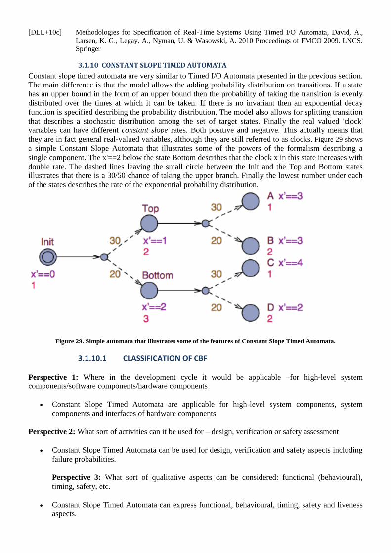
[DLL+10c] Methodologies for Specification of Real-Time Systems Using Timed I/O Automata, David, A.,
Larsen, K. G., Legay, A., Nyman, U. & Wasowski, A. 2010 Proceedings of FMCO 2009. LNCS.
Springer
3.1.10 CONSTANT SLOPE TIMED AUTOMATA
Constant slope timed automata are very similar to Timed I/O Automata presented in the previous section.
The main difference is that the model allows the adding probability distribution on transitions. If a state
has an upper bound in the form of an upper bound then the probability of taking the transition is evenly
distributed over the times at which it can be taken. If there is no invariant then an exponential decay
function is specified describing the probability distribution. The model also allows for splitting transition
that describes a stochastic distribution among the set of target states. Finally the real valued 'clock'
variables can have different constant slope rates. Both positive and negative. This actually means that
they are in fact general real-valued variables, although they are still referred to as clocks. Figure 29 shows
a simple Constant Slope Automata that illustrates some of the powers of the formalism describing a
single component. The x'==2 below the state Bottom describes that the clock x in this state increases with
double rate. The dashed lines leaving the small circle between the Init and the Top and Bottom states
illustrates that there is a 30/50 chance of taking the upper branch. Finally the lowest number under each
of the states describes the rate of the exponential probability distribution.
Figure 29. Simple automata that illustrates some of the features of Constant Slope Timed Automata.
3.1.10.1 CLASSIFICATION OF CBF
Perspective 1: Where in the development cycle it would be applicable –for high-level system
components/software components/hardware components
Constant Slope Timed Automata are applicable for high-level system components, system
components and interfaces of hardware components.
Perspective 2: What sort of activities can it be used for – design, verification or safety assessment
Constant Slope Timed Automata can be used for design, verification and safety aspects including
failure probabilities.
Perspective 3: What sort of qualitative aspects can be considered: functional (behavioural),
timing, safety, etc.
Constant Slope Timed Automata can express functional, behavioural, timing, safety and liveness
aspects.
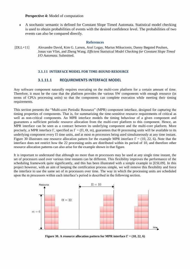
Perspective 4: Model of computation
A stochastic semantic is defined for Constant Slope Timed Automata. Statistical model checking
is used to obtain probabilities of events with the desired confidence level. The probabilities of two
events can also be compared directly.
References
[DLL+11] Alexandre David, Kim G. Larsen, Axel Legay, Marius Mikucionis, Danny Bøgsted Poulsen,
Jonas van Vliet, and Zheng Wang. Efficient Statistical Model Checking for Constant Slope Timed
I/O Automata. Submitted.
3.1.11 INTERFACE MODEL FOR TIME-BOUND RESOURCE
3.1.11.1 REQUIREMENTS INTERFACE MODEL
Any software component naturally requires executing on the multi-core platform for a certain amount of time.
Therefore, it must be the case that the platform provides the various SW components with enough resource (in
terms of CPUs processing units) so that the components can complete execution while meeting their timing
requirements.
This section presents the ―Multi-core Periodic Resource‖ (MPR) component interface, designed for capturing the
timing properties of components. That is, for summarizing the time-sensitive resource requirements of critical as
well as non-critical components. An MPR interface models the timing behaviour of a given component and
guarantees a sufficient periodic resource allocation from the multi-core platform to this component. Hence, an
MPR interface can be seen as a contract between its underlying component and the multi-core platform. More
precisely, a MPR interface specified as = (, , m), guarantees that processing units will be available to its
underlying component every time units, and at most m processors being used simultaneously at any time instant.
Figure 30 illustrates one resource allocation pattern for the example MPR interface = (10, 22, 6). Note that the
interface does not restrict how the 22 processing units are distributed within its period of 10, and therefore other
resource allocation patterns can also arise for the example shown in that figure.
It is important to understand that although no more than m processors may be used at any single time instant, the
set of processors used over various time instants can be different. This flexibility improves the performance of the
scheduling framework quite significantly, and this has been illustrated with a simple example in [ESL09]. In this
project however, with an aim of keeping the certification process simple, we will remove this flexibility and force
the interface to use the same set of m processors over time. The way in which the processing units are scheduled
upon the m processors within each interface‘s period is described in the following section.
Figure 30. A resource allocation pattern for MPR interface = (10, 22, 6)

3.1.11.2 TECHNIQUES FOR MPR INTERFACE SCHEDULING
To schedule a MPR interface on the multi-core platform, we transform into a set of periodic tasks. A periodic
task i, which periodically requires Ci processing units within a period of Ti time units, is specified as i = (Ti, Ci).
An important restriction of each task i is that the Ci units must be provided in a sequential manner, i.e., the task
cannot be scheduled on more than one processor at any time instant. One of the advantages of transforming MPR
interfaces into sets of periodic tasks is that well-established techniques, such as those in [OB98, LDG01, BaFi06,
FBB06], can then be used to schedule these tasks (and hence the MPR interfaces) on the multi-core platform.
Given a MPR interface = (, , m), we transform it into the following periodic task set :
where
It has been proved in [ESL09] that this transformation is correct, that is the amount of resource collectively
required by all the periodic tasks in is at least as much as the resource requirement of the MPR interface . As an
example, let us again consider the MPR interface = (10, 22, 6) introduced in the previous section. According to
the method explained above, this interface is transformed into the periodic task {1 , 2 , 3} (since k =
⌈ ⌉ = 3), where 1 = 2 = (10, 10) and 3 = (10, 2). Figure 31 shows one possible schedule for this task set,
and as can be seen the resource allocation is at least as much as the resource allocation of the MPR interface in
Figure 30.
Figure 31. A schedule for periodic task set {1 = (10, 10), 2 = (10, 10), 3 = (10, 2)}
A simple technique to schedule such a task set is to assign one entire processor to each task 1, 2, ...,k-1, and let
k share a processor with the other component interfaces; on such shared processors, tasks can be scheduled using
well-established single processor scheduling algorithms such as Rate Monotonic [LiLa73]. In addition to ensuring
no wastage of processing capacity upon the (k-1) processors assigned to the first (k-1) tasks, this strategy has the
important property that any interface shares one and only one processor with other interfaces. Such a minimal
processor-sharing scheme between components will facilitate modular certification, without incurring significant
wastage of processing capacity.
3.1.11.3 MINIMUM RESOURCE ALLOCATION OF MPR INTERFACES
A single MPR interface can result in several resource allocation patterns depending on how the processing units are
distributed within the specified period. For example, consider the MPR interface = (10, 22, 6) and its periodic
task set {1 , 2 , 3} illustrated in Figure 31. This figure shows one possible allocation pattern for but other
patterns can be easily obtained; for example by shifting the allocations of task 3 to the right (i.e., later in time)
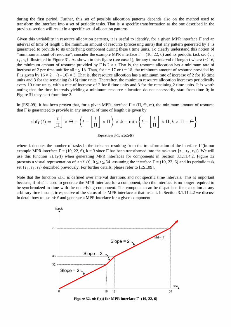
during the first period. Further, this set of possible allocation patterns depends also on the method used to
transform the interface into a set of periodic tasks. That is, a specific transformation as the one described in the
previous section will result in a specific set of allocation patterns.
Given this variability in resource allocation patterns, it is useful to identify, for a given MPR interface and an
interval of time of length t, the minimum amount of resource (processing units) that any pattern generated by is
guaranteed to provide to its underlying component during these t time units. To clearly understand this notion of
―minimum amount of resource‖, consider the example MPR interface = (10, 22, 6) and its periodic task set {1 ,
2 , 3} illustrated in Figure 31. As shown in this figure (see case 1), for any time interval of length t where t ≤ 16,
the minimum amount of resource provided by is 2 × t. That is, the resource allocation has a minimum rate of
increase of 2 per time unit for all t ≤ 16. Then, for t = 17 or t = 18, the minimum amount of resource provided by
is given by 16 × 2 + (t - 16) × 3. That is, the resource allocation has a minimum rate of increase of 2 for 16 time
units and 3 for the remaining (t-16) time units. Thereafter, the minimum resource allocation increases periodically
every 10 time units, with a rate of increase of 2 for 8 time units and 3 for the remaining 2 time units. It is worth
noting that the time intervals yielding a minimum resource allocation do not necessarily start from time 0; in
Figure 31 they start from time 2.
In [ESL09], it has been proven that, for a given MPR interface = (, , m)the minimum amount of resource
that is guaranteed to provide in any interval of time of length t is given by
where k denotes the number of tasks in the tasks set resulting from the transformation of the interface (in our
example MPR interface = (10, 22, 6), k = 3 since has been transformed into the tasks set {1 , 2 , 3})We will
use this function sbf(t) when generating MPR interfaces for components in Section 3.1.11.4.2. Figure 32
presents a visual representation of sbf(t), 0 ≤ t ≤ 34, assuming the interface = (10, 22, 6) and its periodic task
set {1 , 2 , 3} described previously. For further details, please refer to [ESL09].
Note that the function sbf is defined over interval durations and not specific time intervals. This is important
because, if sbf is used to generate the MPR interface for a component, then the interface is no longer required to
be synchronized in time with the underlying component. The component can be dispatched for execution at any
arbitrary time instant, irrespective of the status of its MPR interface at that instant. In Section 3.1.11.4.2 we discuss
in detail how to use sbf and generate a MPR interface for a given component.
Figure 32. sbf(t) for MPR interface =(10, 22, 6)
Equation 3-1: sbf(t)
References
[BaFi06] Sanjoy Baruah and Nathan Fisher, The Partitioned Multiprocessor Scheduling of Deadline-
constrained Sporadic Task Systems, In IEEE Transactions on Computers, Volume 55, Number 7,
pages 918 – 923, 2006.
[FBB06] Nathan Fisher, Sanjoy Baruah, and Theodore P. Baker, ―The Partitioned Scheduling of Sporadic
Tasks according to Static-priorities‖, In Proceedings of Euromicro Conference on Real-Time
Systems (ECRTS), pages 118 – 127, 2006.
[LiLa73] C. L. Liu and J. Layland, Scheduling Algorithms for Multiprogramming in a Hard Real-time
Environment. Journal of the ACM, Volume 20, Number 1, pages 46 – 61, 1973.
[LDG01] J. M. Lopez, J. L. Diaz, and D. F. Garcia. Minimum and Maximum Utilization Bounds for
Multiprocessor RM Scheduling. In Proceedings of Euromicro Conference on Real-Time Systems
(ECRTS), pages 67 – 75, 2001.
[OB98] Dong-Ik Oh and Theodore Baker, ―Utilization Bounds for n-processor Rate Monotone Scheduling
with Static Processor Assignment‖, In Real-Time Systems Journal, Springer Netherlands, Volume
15, Number 2, pages 183 – 192, 1998.
[ESL09] Arvind Easwaran, Insik Shin, and Insup Lee, Optimal Virtual Cluster-based Multiprocessor
Scheduling, In Real-Time Systems Journal, Springer Netherlands, Volume 43, Number 1, pages 25
– 59, September 2009.
3.1.11.4 COMPONENT MODEL AND ANALYSES FOR TIME-BOUND RESOURCE
REQUIREMENTS
In this section we present our modelling framework to capture the time-dependent resource requirements of critical
as well as non-critical components. We also discuss how to generate a MPR interface for a component modelled in
this framework. Finally, we discuss the advantages of this modelling and analysis framework from the perspective
of modular certification.
3.1.11.4.1 COMPONENT MODEL
The workload of each component is described using a set of periodic or sporadic tasks. A periodic task i is
released every Ti time units and requires executing for at most Ci time units upon each release. Furthermore, every
task is subject to hard real-time constraint, i.e., whenever the task is released, it must complete execution by a
deadline of Di Ci, relative to its releasing time. A sporadic task is similar to a periodic task except that its
parameter Ti denotes the minimum interval of time between successive task releases, instead of the exact
separation. Formally, each periodic or sporadic task is specified as i = (Ti, Ci, Di).
This workload model is general enough to capture both time-triggered as well as event-triggered resource
requirements, and task dependencies within and across components can also be captured by using the task
deadlines (Di) as a trigger for successive dependent tasks. We assume that the worst-case execution time Ci of task
i also includes penalties arising from cache-related delays and contentions on the memory bus. Such a Ci can be
computed using techniques proposed in [ABJ01, HaPu09, AEL10].
We consider a Hierarchical Scheduling Framework (HSF), under which a set of critical and non-critical
components are globally scheduled on the multi-core platform (through their MPR interfaces), and each component
in turn locally schedules its workload (i.e., its set of tasks). In this two-level scheduling framework, we support
several local scheduling policies including the well-known Rate Monotonic and Earliest Deadline First policies to

schedule the workload of the components [ESL09], and we use the policy described in Section 3.1.11.2 to schedule
the interfaces on the multi-core platform.
Figure 33. System H comprised of components COMP1 and COMP2
The Hierarchical Scheduling Framework has already been successfully used to model time-dependent resource
requirements in ARINC-653 part I, which defines a software interface between the operating system of an avionics
computer and the application software and which is part of the ARINC standards adopted by the aviation industry.
Details regarding the ARINC-653 standard can be obtained in [ARINC], and our ARINC-653 specific modelling
efforts for single processor platforms can be studied in [ELS+09]. As an example, consider the system H shown in
Figure 33. It has 2 components COMP1 and COMP2, each comprising of 5 periodic tasks scheduled under Rate
Monotonic policy. Under this policy, priorities are assigned to tasks within the component according to their
period: the smaller the period, the higher the priority. The entire system must be scheduled on a multi-core
platform comprised of 5 processors.
It is worth noting that more general workload models can be easily supported in this framework, including
modelling of dispatch jitter for tasks as in [ELS+09] and task graphs as in [AEF+08]. Jitter models bounded
unpredictability in the dispatch of tasks arising (for example due to unpredictable communication delays), and task
graphs model general dispatch dependencies between tasks.
3.1.11.4.2 MPR INTERFACE GENERATION PROCEDURE
Recall from Section 3.1.11.3 that the supply bound function sbf(t) of a MPR interface denotes the minimum
guaranteed resource allocation by in any time interval of duration t. Analogously, let us now introduce the
demand bound function dbfCOMP(t) of a component COMP, which denotes the maximum amount of resource that
a component COMP can require in any time interval of duration t. This function dbf depends not only on the task
model of component COMP, but also on its local scheduling policy. Let us consider component COMP1 presented
in the previous section. It is easy to see that:
within the first 10 time units, COMP1 requires 8 processing units, because both tasks 1 and 3 require 4
time units within [0,10].
within the first 20 time units, COMP1 requires 42 processing units. Indeed, tasks 2, 4 and 5 require 8, 8
and 10 time units within [0,20], respectively, and both tasks 1 and 3 are released twice in this time
interval, hence executing for 2 × 4 = 8 time units each. This yields an amount of 8 + 8+ 10 + 8 + 8 = 42
time units requested within the time interval [0, 20].
After the time-instant 20, the demand of these tasks is periodic with a period of 20 time units. Likewise, the
demand bound function for component COMP2 can also be computed, and these two functions are presented in
Figure 34 and Figure 35, respectively.
As stated earlier, function dbf depends on the local scheduling policy of the component. In fact, it also depends on
how the local scheduler assigns processors to tasks; whether tasks are pinned to processors or allowed to migrate.

Because of this variability, we do not present a general definition of dbf in this report, and refer readers to various
past publications for the same [ESL09, BCL05, ABJ01].
Figure 34. dbfCOMP1(t) for system H
Figure 35. dbfCOMP2(t) for system H
To generate a MPR interface for a component COMP, we now present a technique that uses the supply bound
function sbf of the MPR model and the demand bound function dbf of COMP. The following equation,
presented in [ESL09], gives the condition for a MPR model to be a viable interface for component COMP.
Equation 1: Schedulability condition
The above condition states that for all time interval durations, the minimum resource allocation of is at least as
much as the maximum resource requirement of COMP. This means that is guaranteed to satisfy the resource
demand of COMP in any time interval, irrespective of the actual resource allocation pattern of and actual
resource demand of COMP in that interval. Thus, MPR interface correctly summarizes the resource requirements
of component COMP, and further does so without any assumed time-synchronization between and COMP. The
latter follows from the fact that sbf and dem are defined over interval durations, rather than specific time
intervals.
Figure 36. MPR interface schedule for system H
Consider the system H presented in Figure 33 and the MPR interface = (10, 22, 6) whose sbf is presented in
Figure 32. It is easy to verify that the demand bound function of component COMP1 (presented in Figure 34) and
the supply bound function of satisfy Equation 3-1. Therefore is a viable MPR interface for COMP1. Likewise,
it can be easily verified that the MPR interface = (10, 26, 6) is a viable interface for component COMP2; it
guarantees 48 processing units in any time interval of duration 20 time units. Now, and can be transformed
into periodic task sets
{1=(10,10), 2=(10,10), 3=(10,2)}
and
{4=(10,10), 5=(10,10), 6=(10,6)}
respectively, using the technique presented in Section 3.1.11.2. Tasks 1, 2, 4 and 5, can be assigned to one
processor each, and tasks 3 and 6 can share one processor. The resulting schedule is as shown in Figure 36. Thus,
system H can be successfully scheduled on a multi-core platform comprised of 5 processing cores.
3.1.11.4.3 DISCUSSIONS
MPR interface based hierarchical scheduling frameworks are very effective for scheduling component-based
mixed-criticality systems on multi-core platforms. MPR interfaces temporally isolate components from each other,
so that one misbehaving component cannot impact the resource availability of other components. Each component
will be allocated resource based on its interface, irrespective of the actual demand of the component, which may or
may not conform to pre-specified requirements. The interface in this case acts like a pre-defined contract between
the component and the system. Thus, critical components may co-exist and share resources with non-critical ones,
without jeopardizing their resource allocations.
MPR interfaces also provide support for modular certification. Each component can be certified via its interface
independently of other components. This involves showing that the interface will satisfy the resource requirements
of the component at all times. Equation (2) can form the analytical basis for this certification step. Once the
interfaces of all the components in a system are certified, the overall system can be certified using those interfaces
alone. This step involves certifying the transformation step from a MPR interface to periodic tasks, and then
certifying the schedule of those tasks on the multi-core platform. The former is straightforward and is already
accomplished as a part of the interface certification process; certifying an interface involves validating its sbf,
which in turn involves validating the transformation. The latter is highly simplified because, as described in
Section 3.1.11.2, any two components share at most one processor between them.
The analytical basis of this framework provides guarantees on safe and dependable execution, by ensuring that all
the timing properties of components will be satisfied. Further, the interface generation and scheduling procedures
based on Equation (2) and Section 3.1.11.2, ensure that available resources are utilized in a highly efficient
manner.
The presented framework relates to various RECOMP requirements as follows:
1. It provides temporal isolation between components, so that applications belonging to one component can
use H/W resources independently of applications belonging to other components in the system, at least
with respect to the time domain (in accordance with Req. No. CDR-38-006).
2. It provides isolation of faults and eventually reduces the effort necessary for system verification (Req. No.
ARR-25-028).
3. It allows every component to schedule its workload (i.e., its task set) using a partitioned scheduling policy,
hence complying with Req. No. CDR-38-005.
4. It provides a compositional technique, wherein software with different criticality can be organized into
different components. That is, this framework supports separation of software with different criticality.
E.g. Non-safety critical software from safety-critical software. (Req. No. CDR-19-005)
5. Although not discussed in this report, the presented framework can also be used to model different levels
of abstractions for components (Req. No. CDR-38-063). For example, this can be achieved by allowing
each component to be abstracted into an interface comprising of one or more MPR interfaces, where each
MPR interface abstracts the resource requirements of a subset of component tasks. In this case, the
interface becomes richer (and hence more accurate) as it encompasses more MPR interfaces.
6. It can be used to check compatibility between components in terms of their resource requirements, thus
providing design-time guarantees on resource availability (Req. No. CDR-22-008).

7. It can also support different modes of operation, either by generating mode-specific component interfaces
at design-time, or by allowing component refinement at run-time (Req. No. CDR-22-003). In the latter
case, care must be taken to ensure that the refinement does not violate interface assumptions.
References
[ABJ01] Bjorn Andersson, Sanjoy Baruah, and Jan Jonsson, ―Static-priority Scheduling on
Multiprocessors‖, In Proceedings of IEEE Real-Time Systems Symposium (RTSS), pages 193 –
202, 2001.
[AEF+08] Madhukar Anand, Arvind Easwaran, Sebastian Fischmeister, and Insup Lee, "Compositional
Feasibility Analysis of Conditional Real-Time Task Models", IEEE Symposium on Object
Oriented Real-Time Distributed Computing (ISORC), pages 391 – 398, 2008.
[AEL10] Bjorn Andersson, Arvind Easwaran, and Jinkyu Lee, ―Finding an Upper Bound on the Increase in
Execution Time Due to Contention on the Memory Bus in COTS-Based Multicore Systems‖, In
SIGBED Review, Special Issue on the Work-in-Progress (WIP) Session at the IEEE Real-Time
Systems Symposium (RTSS), Volume 7, Number 1, January 2010.
[ARINC] ARINC standards, ―http://www.aviation-ia.com/standards/index.html‖.
[BCL05] Marko Bertogna, Michele Cirinei, and Giuseppe Lipari, ―New Schedulability Tests for Real-time
Task Sets Scheduled by Deadline Monotonic on Multiprocessors‖, In Proceedings of International
Conference on Principles of Distributed Systems (IPDPS), pages 306 – 321, 2005.
[ELS+09] Arvind Easwaran, Insup Lee, Oleg Sokolsky, and Steve Vestal, "A Compositional Scheduling
Framework for Digital Avionics Systems", IEEE International Conference on Embedded and Real-
Time Computing Systems and Applications (RTCSA), pages 371 – 380, 2009.
[ESL09] Arvind Easwaran, Insik Shin, and Insup Lee, ―Optimal Virtual Cluster-based Multiprocessor
Scheduling‖, In Real-Time Systems Journal, Springer Netherlands, Volume 43, Number 1, pages
25 – 59, September 2009.
[HaPu09] D. Hardy and I. Puaut, ―Estimation of Cache Related Migration Delays for Multi-core Processors
with Shared Instruction Caches‖, In International Conference on Real-Time and Network Systems
(RTNS), pages 45 – 54, 2009.
3.1.12 TIME-CONSTRAINED AUTOMATA: THE MODEL BEHIND OASIS AND PHAROS
Time constrained automata (TCA) [LDA+10] is a formal task model to accurately describe the timing requirements
of a program, represented by an automata, independently from the execution time of this program. It features a
highly expressive model (with multiple start time and deadlines, aperiodicity, linear dependency between jobs, and
dynamic choice between different timing behaviours), optimal scheduling algorithm and tractable exact feasibility
analysis, and non-blocking deterministic communications.
TCA is used as the task model for OASIS [DaAU98] and one of the task model for PharOS [ACD+10] , which
automatically extract the TCA from annotated source code, and use them to perform exact the offline
schedulability analysis, online actual scheduling, or computation of the buffer sizes needed for communication.
TCA is based on only two simple primitives. "after" constrains all succeeding jobs to execute after a certain date.
"before" constrains all preceding job to end before a certain date. In other words, these primitives constrain job
execution to a certain interval. The methodology consists in cutting the program into jobs that execute in sequence,
and to insert the timing primitives in between to constrain the execution of the program. The model is independent
of the actual schedule, and scheduling algorithm can be used, as long as the timing constraints are fulfilled.
Further extensions to the model (handling choice between different possible succeeding jobs, handling loops)
allows to extract the TCA automatically from the control flow graph of an annotated (C) code, in a language called
PsyC.
Various interesting properties and algorithms have been demonstrated for this model, notably:
That it can be optimally scheduled on single processor computers using a variant of EDF, i.e. the highest
efficiency can be reached. Moreover, there also exists an optimal scheduling algorithm for
multiprocessor, despite the dynamic behaviour of the tasks [LDA+08].
That tractable exact schedulability analysis can be performed, meaning that it can be predicted whether all
the deadlines of the application can be met using an automated tool.
That appropriate communication primitives can be used that guarantee determinism, that are non-blocking,
and guarantee bounded communication delivery time. Determinism means that the outcome of the
execution is the same, despite the parallel execution (or the scheduling algorithm used). Non-blocking
means that the sender or receiver of a communication does not wait for the other communication endpoint.
To summarize, TCA is a highly efficient model with many interesting mathematical properties which have proven
very useful for all the industrial projects that used it.
References
[LDA+10] M. Lemerre, V. David, Ch. Aussaguès, and G. Vidal-Naquet. "An Introduction to Time-
Constrained Automata" EPCTS Volume on 3rd
Interaction and Concurrency Experience Workshop
(ICE'10), Amsterdam, Netherlands
[LDA+08] M. Lemerre, V. David, Ch. Aussaguès, and G. Vidal-Naquet. "Equivalence between Schedule
Representations: Theory and Applications." In Proceedings of the 2008 IEEE Real-Time and
Embedded Technology and Applications Symposium (April 22 - 24, 2008). RTAS. IEEE
Computer Society, Washington, DC, 237-247.
[DaAu98] V. David and C. Aussaguès, "A method and a technique to model and ensure timeliness in safety
critical real time systems", Proceedings of the 4th IEEE International Conference on Engineering
of Complex Computer Systems, Monterey, California, USA, 1998
[ACD+10] C. Aussaguès, D. Chabrol, V. David (CEA), D. Roux, N. Willey, A.Tournadre (Delphi) and M.
Graniou (PSA), "PharOS, a multicore OS readyfor safety-related automotive systems: results and
future prospects", Proceedings of the Embedded Real-Time Software and Systems (ERTS22010),
Toulouse, France, May 2010
3.1.13 EVENT-BASED TIMING MODEL
TU Braunschweig will contribute an abstract system model that focuses on timing properties of the multi-core
platform. This approach covers the classical perception of real-time theory, where formal modelling and analysis
techniques are applied to verify the correct system timing even in critical situations such as transient peak loads.
Further on the effect of transient errors on real-time capabilities will be covered by the proposed model. We will
propose a model for an efficient checkpointing mechanism based on hardware supported fingerprinting. The model
enables task-level redundancy with configurable granularity of checkpoints. Within the scope of RECOMP this
fine-grained task level redundancy approach is of particular interest due to its ability to design mixed-critical
systems in an efficient way.
3.1.13.1 THE BASIC SYSTEM MODEL
The multi-core platform is modelled as a set of interconnected processing cores. Different applications are running
on that platform; each application might comprise multiple software tasks which are mapped to different cores and
communicate via the system interconnect.
Considering a concrete system, the model has to be parameterized such that the properties of the corresponding
model instance match to those of the real system. The parameter space contains information concerning the
physical properties of the platform, e.g. type and number of cores, as well as a specification of the application- and
the system software that is running on the platform. The software specification describes essential timing
properties such as task activation patterns, execution times and context switch times as well as information on the
scheduling of tasks or communication between different applications and tasks. These parameters might be
specified either as exact values (e.g. scheduling priorities) or using upper- and lower bounds (e.g. execution times,
activation frequency).
3.1.13.2 THE COMPOSITIONAL TIMING MODEL: TASK COUPLING USING EVENT STREAMS
Essentially the system model consists of a hardware part (CPUs and interconnect) and a software part (applications
and task). Connection between these two parts is provided by the static mapping function which assigns a set of
tasks to each CPU. This mapping represents a CPU-oriented partitioning of the overall task set into disjoint
subsets.
Another approach with a more application-oriented view is task partitioning according to functional dependencies.
The overall task set is partitioned into disjoint subsets such that tasks within one subset are functionally dependent,

e.g. due to data dependencies. A special kind of data dependency is the precedence relation that occurs if one task
produces data that are consumed by another task . Assuming an event triggered activation pattern, is
activated at that point in time completes its execution.
This kind of dependency is also referred to as a function chain. Due to the precedence relation function chaining
induces timing implications between tasks. To describe these implications in a general and powerful way, the
notation of event streams is applied. An event stream is a numerical representation of the possible timing of event
arrivals [Ric05]. It is characterized by a number of functions. The lower bound arrival function defines the
minimum number of event arrival within an interval of length , while the upper bound arrival function
specifies the maximum number. Similarly and define the minimum and maximum time between
event arrivals. - and -functions are mathematically equivalent such that the following remarks will be based on
the -functions.
Applying the notation of event streams, timing information can be propagated along a function chain. For this
purpose, the output event stream of each task must be derived by local analyses of the corresponding component
and propagated to the successor task. At the successor task, this event stream serves as the input event stream, i.e. it
characterizes the arrival of events which trigger the task to execute.
Figure 37. Coupling of tasks and components using event streams
To derive the output event stream of task by a local analysis of the corresponding CPU, the behaviour of that
CPU must be specified. This specification includes hardware as well as OS-related properties. Concerning the real-
time capabilities, the scheduling of the core is of special interest. Normally more than one task is mapped to the
core, i.e. multiple requests for CPU time might occur simultaneously. In that case the scheduler resolves this access
conflict and allocates processor time to the specific tasks according to a previously defined policy.
In summary this model represents a compositional timing model, where local timing entities are coupled by event
streams which propagate the timing information between these entities. Timing implications arise in the different
dimensions: on component level due to scheduling and on application level due to event stream propagation. This
concept is exploited for the analysis, where local timing analysis and propagation of the resulting event streams can
be executed in alternating order.
3.1.13.3 FAULT-TOLERANCE MODEL: FINE GRAINED TASK LEVEL REDUNDANCY
For the design of safety-critical systems it is essential to provide safety guarantees even in the presence of
unpredictable random events such as transient faults. Whenever a fault occurs it might cause an internal system
error. In this case suitable mechanisms must be adopted to either correct this error or to initiate a transition to a safe
state. Even though the transition to the safe state might satisfy certification demands it is usually associated with a
degradation of service. Thus, correcting errors whenever possible appears to be the more promising alternative.
Even though error correction seems to be an adequate technique from the functional point of view, it basically
induces temporal overhead that might affect the real-time capabilities. Applying well-known software approaches
such as re-execution of tasks [Pul01] or N-version programming [Ric05] causes this overhead to be quite large.
Hence, tremendous over-provisioning would be necessary to assure compliance with all real-time requirements.
The same holds for hardware assisted technologies. Lockstep-based double (DMR) or triple (TMR) modular
redundancy for example runs replicated cores in parallel. In this case the error detection latency is negligible.
However, due to the duplication
output event
streams
input event
streams
comp 1
scheduling
comp 1
P2
P1
comp 2
scheduling
comp 2
P4
P3
event streams
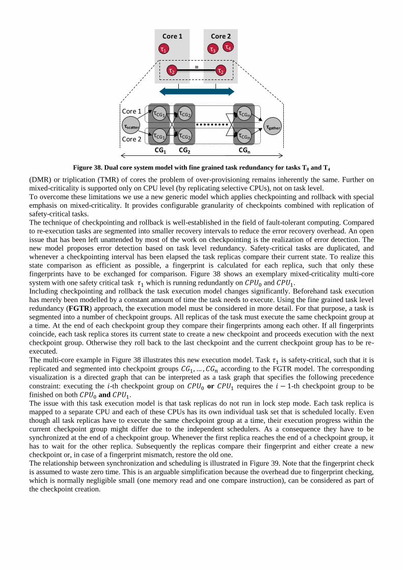
Figure 38. Dual core system model with fine grained task redundancy for tasks T0 and T4
(DMR) or triplication (TMR) of cores the problem of over-provisioning remains inherently the same. Further on
mixed-criticality is supported only on CPU level (by replicating selective CPUs), not on task level.
To overcome these limitations we use a new generic model which applies checkpointing and rollback with special
emphasis on mixed-criticality. It provides configurable granularity of checkpoints combined with replication of
safety-critical tasks.
The technique of checkpointing and rollback is well-established in the field of fault-tolerant computing. Compared
to re-execution tasks are segmented into smaller recovery intervals to reduce the error recovery overhead. An open
issue that has been left unattended by most of the work on checkpointing is the realization of error detection. The
new model proposes error detection based on task level redundancy. Safety-critical tasks are duplicated, and
whenever a checkpointing interval has been elapsed the task replicas compare their current state. To realize this
state comparison as efficient as possible, a fingerprint is calculated for each replica, such that only these
fingerprints have to be exchanged for comparison. Figure 38 shows an exemplary mixed-criticality multi-core
system with one safety critical task which is running redundantly on and .
Including checkpointing and rollback the task execution model changes significantly. Beforehand task execution
has merely been modelled by a constant amount of time the task needs to execute. Using the fine grained task level
redundancy (FGTR) approach, the execution model must be considered in more detail. For that purpose, a task is
segmented into a number of checkpoint groups. All replicas of the task must execute the same checkpoint group at
a time. At the end of each checkpoint group they compare their fingerprints among each other. If all fingerprints
coincide, each task replica stores its current state to create a new checkpoint and proceeds execution with the next
checkpoint group. Otherwise they roll back to the last checkpoint and the current checkpoint group has to be re-
executed.
The multi-core example in Figure 38 illustrates this new execution model. Task is safety-critical, such that it is
replicated and segmented into checkpoint groups according to the FGTR model. The corresponding
visualization is a directed graph that can be interpreted as a task graph that specifies the following precedence
constraint: executing the -th checkpoint group on or requires the -th checkpoint group to be
finished on both and .
The issue with this task execution model is that task replicas do not run in lock step mode. Each task replica is
mapped to a separate CPU and each of these CPUs has its own individual task set that is scheduled locally. Even
though all task replicas have to execute the same checkpoint group at a time, their execution progress within the
current checkpoint group might differ due to the independent schedulers. As a consequence they have to be
synchronized at the end of a checkpoint group. Whenever the first replica reaches the end of a checkpoint group, it
has to wait for the other replica. Subsequently the replicas compare their fingerprint and either create a new
checkpoint or, in case of a fingerprint mismatch, restore the old one.
The relationship between synchronization and scheduling is illustrated in Figure 39. Note that the fingerprint check
is assumed to waste zero time. This is an arguable simplification because the overhead due to fingerprint checking,
which is normally negligible small (one memory read and one compare instruction), can be considered as part of
the checkpoint creation.
Core 1 Core 2
=
τ1
τ2 τ2
τCG1
τscatter
τCG1
τCG2
τCG2
τCGn
τCGn
τgather
Core 1
Core 2
τ3τ4
CG1 CG2 CGn

Figure 39. Task T2 is replicated and has to be synchronized at the end of each checkpoint group
3.1.13.4 ERROR AND RELIABILITY MODEL
Based on the FGTR model system timing can be verified for the error-free case as well as for a given error pattern.
However, transient errors are random events which are not predictable at design time. To specify their occurrence a
statistical error model is required. It has been pointed out in practice that the Poisson process is a suitable model to
characterize the occurrence of transient errors:
We apply this error model to derive probabilities for certain system behaviour during an interval of time. Of special
interest is the probability that a certain task will not fail during that time. This metrics is commonly applied as a
measure for reliability. In the context of real-time systems the system fails if either a timing constraint is violated
or a task output is logically incorrect.
The FGTR-based mixed-criticality approach combines fault-tolerant tasks with non-fault tolerant tasks on the same
platform. As a consequence reliability considerations depend on the type of the task:
Fault-tolerant tasks: Errors are normally corrected, but timing constraints might be violated due to recovery
overhead. Residual error probability depends on error coverage of checkpointing and the robustness of the
checkpoint memory. The reliability assessment includes the probability that neither a timing constraint
will be violated in nor that any kind of logical failure will occur due to undetected errors or checkpoint
corruption.
Non-fault-tolerant tasks: Errors are not detected such that each error directly causes the corresponding
function to fail. Further on the function might fail due to violated timing constraints of the task. Timing
constraint violation of a non-fault-tolerant task can occur because other tasks allocate additional CPU time for
error recovery. The reliability assessment includes the probability that neither a timing constraint will
be violated in nor that any error that corrupts the non-fault tolerant task will occur.
References
[Ric05] K. Richter, ―Compositional scheduling analysis using standard event models‖, PhD thesis,
Technische Universität Braunschweig, 2005.
[Avi85] A. Avizienis, "The N-Version Approach to Fault-Tolerant Software", IEEE Transactions on
Software Engineering, Volume SE-11, No. 12, pp. 1491-1501, 1985.
[Pul01] L.L. Pullum. ―Software Fault Tolerance Techniques and Implementation‖, Artech House
Publishers, 2001.
3.1.14 EVENT-BASED POWER CONSUMPTION MODEL
3.1.14.1 MOTIVATION
Time and space partitioning are mandatory for fault containment in safety-critical systems [HoDr93]. Power is
another resource that has to be shared between the individual applications and/or that that could influence other
applications of other or the same criticality running on the same platform. Power can be described by a dynamic
and a static part. The static part is mainly due to leakage and the dynamic part can further be divided into switching
power and short-circuit power,

P Pdyn Psta Pswi Psc Pleak.
Formula 3-1
The switching power has the largest share of power consumption in CMOS circuits and can be expressed by
Pswi CLV2 f ,
Formula 3-2
where V is the supply voltage, CL are the parasitic capacitances that are charged and discharged with the frequency
f when the corresponding component is active [BhMu10]. The switching activity α is highly dependent on the
running applications and their input data [PePa08]. Therefore the running applications have a high impact on the
dynamic power consumption.
The overall power budget of a chip is defined at design time based on packaging and cooling solutions, battery
capacity (if battery powered) and environmental conditions. Keeping the power budget is especially important for
battery-powered devices [PePa08] but power consumption is also critical in other (non-battery-powered) systems
because a high local power consumption could lead to a hot spot that could influence neighbouring components,
reduce the life-time and reliability of the whole chip [SSS04]. An application that does not adhere to its power
budget may increase the overall power consumption of the chip above a limit that has to be kept to be able to give
power guarantees to other applications (power isolation). Derived from these threats the power consumption in
single components or groups of components that lie close together and the overall power consumption have to be
monitored. To be able to detect an application that is consuming too much power and may endanger the safe
execution of other applications, the power consumption has to be monitored per application.
3.1.14.2 MODEL
The resolution of physical measurement of the dynamic power consumption at run-time is not sufficient to measure
the power consumption of single components on a chip. Moreover, it is impossible to identify the originator
(application) of the consumed energy in a shared component [Bel01]. This makes it impossible to isolate the
dynamic power consumption of different applications.
Bellosa et al. [Bel00] discovered a strong correlation between events in the system, like floating point operations or
cache misses, and the required energy. These mechanisms have been proven by several others [BCM08][GBH09]
to be sufficiently accurate for low-cost and fine-grained run-time power measurement. To be able to measure
power consumption by counting events, power models of all components in the system are required.
These power models assign one or more activating events and the corresponding consumed energy to a component
or to a group of components. The amount and kind of the power events determine the overhead and accuracy of the
power monitoring. The solutions range from very few existing counters available in standard CPUs for
performance measurement [CoMa05] to counters for almost every gate activity [CRR05]. In [CoMa05], the
authors used the two available performance counters of the Intel PXA255 processor to monitor five events,
instructions executed, data dependencies, instruction cache misses, data TLB misses and instruction TLB misses.
With only two counters but five events, multiple runs of their code were necessary for complete power estimation.
Bachmann et al. [BGS10] developed a method to automatically extract power events from a given RTL
description.
The IDA many-core platform (IDAMC, [DiMo11]) developed in WP3 consists of tiles that are based on existing
IPs and are connected by a network-on-chip (NoC). The IPs do not contain any event counters that could be used
for power monitoring. Therefore, we focus on monitoring the power of the IP cores from their external behaviour,
mainly transactions on the local busses and transactions send over the NoC. Cho et al. [CKP08] have already
applied this approach to model the power consumption of memories connected to a local bus.
If the energy for a specific event depends on the state of the corresponding component or on past events, this can
be modelled with an energy interval ([e−,e
+]=[min energy, max energy]). For example, an event for a component
that is in idle state may cost more energy because of a possible wake-up overhead. Another example is writing data
to the same location in memory twice. Writing both times the same data would cost less energy than writing
different data because of the lack of the need to reload the capacitance of that memory location.
For very complex IPs, the power consumption highly depends on their internal behaviour and the internal
behaviour can hardly be observed from the interfaces. For example, the LEON3 core that is used on the IDAMC
consumes ten times the energy of an addition operation for a division operation [BCM08] and cache operations are

not visible from the interfaces at all. Modelling these effects with energy intervals may lead to a poor accuracy or
large overestimation. In this case additional probes to monitor the internal behaviour, like the usage of caches, co-
processors or floating point units, may be required.
Figure 40. Power events in an example dual-core system
Figure 40 shows the timing of two tasks mapped on a example dual-core system. Task T1 is mapped on CPU1 and
T2 is mapped and CPU2 and both tasks access the shared memory. The tasks are periodically activated by separate
events that can be modelled by two event functions each,
T(t) and
T(t).
T(t) specifies the maximum
number of activating events for task T that can occur during any time interval of length ∆t and
T(t) specifies the
minimum number of events [HHJ05]. Schlieker et al. [SNE10] extended this model with the definition of the
shared resource request bound
~
TS
(t).
~
TS
(t) is the maximum amount of requests that may be issued from
a set of tasks T to a shared resource S within a time window of size ∆t. According to the shared resource request
bound, we add the functional unit request bound to increase the accuracy of our power model.
~
TF
(t) is the
maximum amount of requests that may be issued from a set of tasks T to a functional unit F of the CPU, like the
floating point unit or cache, within any time window of size ∆t.
~
TF
(t) defines the minimum amount of
requests. The number of requests for the analysis of a real system can be gathered from simulation or a extended
WCET analysis.
In Figure 40, the orange upward arrows show power events weighted with the corresponding energy for the CPUs
and the memory. The number of power events in the CPUs is equal to the number of activating events for the
functional units inside the CPUs. The number of power events in the memory is equal to the number of resource
requests. The lengths of the arrows symbolize the energy associated with the events.
Following the notation introduced by Schlieker et al.
e~
TS
(t) and
e~
TS
(t) are the maximum and minimum
energy weights for a task T to access the shared resource S. In the example dual-core system shown in Figure 40
the energy consumed on the bus while accessing a shared resource is included in the energy weights
e~
TS
(t) and
e~
TS
(t) of the resource. For more complex interconnects that consume a significant and case dependant amount
of energy, like NoCs, separate request bounds and energy weights are used. The maximum energy required if task
T uses the functional unit F of the CPU is expressed by
e~
TF
(t) and the minimum energy required by
e~
TF
(t).
The weights of the power events are gathered from microbenchmarks [Bel00]. These microbenchmarks consist of a
variable number of operations that exclusively trigger single or a small number of components. For example, one
microbenchmark is only writing to the memory to get the energy required per memory access. On the IDAMC,
there will be microbenchmarks used to characterize all IPs in the local tiles and the NoC. For example, one
microbenchmark sends packets with a different amount of payload via different routes to get the energy per hop
and per packet size.
The overall switching activity of the placed and routed de- sign gathered during simulation of the individual
microbenchmarks is fed into the power analysis tools from EDA vendors, such as Xilinx XPower Analyzer. With
this method, we get the component-wise power consumption for each microbenchmark [BCM08]. From the power
consumption of a specific microbenchmark and the number and type of operations used in it, we calculate the
energy per event (energy weight) using linear regression technique [GBH09].
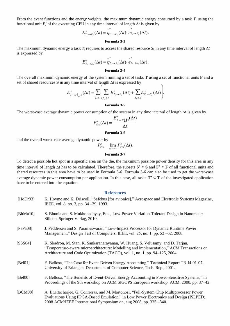
From the event functions and the energy weights, the maximum dynamic energy consumed by a task Ti using the
functional unit Fj of the executing CPU in any time interval of length ∆t is given by
ETi F j
(t) ~
Ti F j
(t) e~
Ti F j
(t) .
Formula 3-3
The maximum dynamic energy a task Ti requires to access the shared resource Sk in any time interval of length ∆t
is expressed by
ETi Sk (t)
~
Ti Sk
(t) e~
Ti Sk
(t).
Formula 3-4
The overall maximum dynamic energy of the system running a set of tasks T using a set of functional units F and a
set of shared resources S in any time interval of length ∆t is expressed by
ETF SU (t) ETi F j
(t) ETi Sk
(t)SkS
F j F
Ti T
.
Formula 3-5
The worst-case average dynamic power consumption of the system in any time interval of length ∆t is given by
Pdyn (t)
ETF SU (t)
t
Formula 3-6
and the overall worst-case average dynamic power by
Pdyn lim
tPdyn
(t).
Formula 3-7
To detect a possible hot spot in a specific area on the die, the maximum possible power density for this area in any
time interval of length ∆t has to be calculated. Therefore, the subsets S∗ ⊂ S and F∗ ⊂ F of all functional units and
shared resources in this area have to be used in Formula 3-6. Formula 3-6 can also be used to get the worst-case
average dynamic power consumption per application. In this case, all tasks T∗ ⊂ T of the investigated application
have to be entered into the equation.
References
[HoDr93] K. Hoyme and K. Driscoll, ―Safebus [for avionics],‖ Aerospace and Electronic Systems Magazine,
IEEE, vol. 8, no. 3, pp. 34 –39, 1993.
[BhMu10] S. Bhunia and S. Mukhopadhyay, Eds., Low-Power Variation-Tolerant Design in Nanometer
Silicon. Springer Verlag, 2010.
[PePa08] J. Peddersen and S. Parameswaran, ―Low-Impact Processor for Dynamic Runtime Power
Management,‖ Design Test of Computers, IEEE, vol. 25, no. 1, pp. 52 –62, 2008.
[SSS04] K. Skadron, M. Stan, K. Sankaranarayanan, W. Huang, S. Velusamy, and D. Tarjan,
―Temperature-aware microarchitecture: Modelling and implementation,‖ ACM Transactions on
Architecture and Code Optimization (TACO), vol. 1, no. 1, pp. 94–125, 2004.
[Bel01] F. Bellosa, ―The Case for Event-Driven Energy Accounting,‖ Technical Report TR-I4-01-07,
University of Erlangen, Department of Computer Science, Tech. Rep., 2001.
[Bel00] F. Bellosa, ―The Benefits of Event-Driven Energy Accounting in Power-Sensitive Systems,‖ in
Proceedings of the 9th workshop on ACM SIGOPS European workshop. ACM, 2000, pp. 37–42.
[BCM08] A. Bhattacharjee, G. Contreras, and M. Martonosi, ―Full-System Chip Multiprocessor Power
Evaluations Using FPGA-Based Emulation,‖ in Low Power Electronics and Design (ISLPED),
2008 ACM/IEEE International Symposium on, aug 2008, pp. 335 –340.
[GBH09] A. Genser, C. Bachmann, J. Haid, C. Steger, and R. Weiss, ―An Emulation-Based Real-Time
Power Profiling Unit for Embedded Software,‖ in Systems, Architectures, Modelling, and
Simulation, 2009. SAMOS‘09. International Symposium on. IEEE, 2009, pp. 67 –73.
[CoMa05] G. Contreras and M. Martonosi, ―Power Prediction for Intel XScale Processors Using Performance
Monitoring Unit Events,‖ in ISLPED ‘05: Proceedings of the 2005 international symposium on
Low power electronics and design. ACM, 2005, pp. 221–226.
[CRR05] J. Coburn, S. Ravi, and A. Raghunathan, ―Power Emulation: A New Paradigm for Power
Estimation,‖ jun 2005, pp. 700 – 705.
[BGS10] C. Bachmann, A. Genser, C. Steger, R. Weiss, and J. Haid, ―Automated Power Characterization
for Run-Time Power Emulation of SoC Designs,‖ in 2010 13th Euromicro Conference on Digital
System Design: Architectures, Methods and Tools. IEEE, 2010.
[DiMo11] J. Diemer and B. Motruk, IDA ManyCore Architecture - Short Description, TU Braunschweig,
Institute of Computer and Computer Engineering, jan. 2011.
[CKP08] Y. Cho, Y. Kim, S. Park, and N. Chang, ―System-Level Power Estimation using an On-Chip Bus
Performance Monitoring Unit,‖ in Computer-Aided Design, 2008. ICCAD 2008. IEEE/ACM
International Conference on, 2008, pp. 149 –154.
[HHJ05] R. Henia, A. Hamann, M. Jersak, R. Racu, K. Richter, and R. Ernst, ―System level performance
analysis - the symta/s approach,‖ Computers and Digital Techniques, IEE Proceedings -, vol. 152,
no. 2, pp. 148 – 166, mar 2005.
[SNE10] S. Schliecker, M. Negrean, and R. Ernst, ―Bounding the shared resource load for the performance
analysis of multiprocessor systems,‖ in Proc. of Design, Automation, and Test in Europe (DATE),
Dresden, Germany, mar 2010.
3.1.15 MODULAR CERTIFICATION AND MODULAR SAFETY CASES
The major goal of RECOMP is to support the modular certification and pre-certification of multi-core components,
this is achieved by developing architectural, both hardware and software, techniques for supporting modularity and
providing the necessary design methods and tools to support the verification and certification processes.
For a RECOMP instantiated system, the overall system can be subdivided into subsystems with different levels of
criticality; each of them can then be individually certified to the appropriate level of criticality, avoiding the full
product certification to the highest criticality level of all subsystems, reducing cost and simplifying the complexity
of certification effort [Obe05]. This process is supported by the definition of Modular Safety Cases [Kel99],
[Kel07], [ScAl05] and provides an independent certification of platform services from applications and
management of independent safety arguments for different functions:
Separating certification of platform services from applications. The certification of the overall system is
supported by a baseline formed by the certified platform services [NiCo00] [Obe05].
Separating certification of different functionalities. Instead of considering the system as a monolithic
block; the certification will be accomplished in an incremental way.
Safety is a system property and assessing the safety of components in isolation does not necessarily ensure that
once integrated they will behave as expected or desired. Guided by Work Package 4.Certification lifecycle issues,
Task 2.3 will support the integration of systems by separately developed, analyzed and implemented components
as part of a modular safety process and ensure that system safety is upheld.
Extending the approach described on [Con07], producing a safety case for a safety critical system integrating
different components, an integrator must demonstrate:
1. That the component does not behave in a way which would lead to unacceptable loss of safety margins:
ensuring undesirable behaviour is managed and/or undesirable behaviour does not exist

2. That the component has not been caused to behave in such a way by other system components:
demonstrating a component uses the component in the manner expected and/or components are protected
from misbehaviour in other components
3. That the component behaves in a way that is adequate to meet basic system safety requirements.
From a technical view, the main challenge here is to ensure and provide evidences of segregation mechanism, used
to partition functions of different integrity levels running on the multi-core platform, would adequately protect
critical program and data memory from corruption by the lower integrity software. The approach will be based on
an analysis of time and physical resources, using systematically interpretations of a number of generic failure
classes to prompt consideration of various hypothetical deviations from designed behaviour of the different
components.
On the other side, from the certification point of view, the traditional approach to certification relies heavily upon a
system being statically defined as a complete entity and the corresponding system safety case being constructed.
However, this is not aligned with the RECOMP scenario, with different teams of companies developing different
components (p.e. middleware, RTOS, hypervisors, cores and networks) at different times and nullifies the benefit
of flexibility in using the potential RECOMP solution and forcing the development of completely new safety cases
for future modifications or additions to the architecture.
A more promising approach is to attempt to establish a modular, compositional, approach to constructing safety
cases that has a correspondence with the modular structure of the underlying architecture [Kel01]. As with systems
architecture it would need to be possible to establish interfaces between the modular elements of the safety
justification such that safety case elements may be safely composed, removed and replaced. Similarly, as with
systems architecture, it will be necessary to establish the safety argument infrastructure required in order to support
such modular reasoning (e.g. an infrastructure argument regarding partitioning being required in order to enable
independent reasoning concerning the safety of two system elements).
Following the Goal Structured Notation (GSN) (a visual means of communicating an argument), defining a safety
case ‗module‘ involves defining the objectives, evidence, argument and context associated with one aspect of the
safety case. Assuming a top-down progression of objectives-argument-evidence, safety cases can be partitioned
into modules both horizontally and vertically, where an argument can determine context or objectives of others.
In defining a safety case module [Kel98] it is essential to identify the ways in which the safety case module
depends upon the arguments, evidence or assumed context of other modules. An argument is ideally a compelling
(obvious to anyone engaged) discussion, which explains why something is what it is or what it should be. It is not a
disagreement, but aims at building a non-ambiguous consensual agreement. It is essential that all system safety
activity is supported by an argument.
A safety case module, should therefore be defined by the following interface:
Objectives addressed by the module
Evidence presented within the module
Context defined within the module
Arguments requiring support from other modules
Inter-module dependencies:
Reliance on objectives addressed elsewhere
Reliance on evidence presented elsewhere
Reliance on context defined elsewhere
The principal need for having such well-defined interfaces for each safety case module arises from being able to
ensure that modules are being used consistently and correctly in their target application context. Safety case
modules can be usefully composed if their objectives and arguments complement each other – i.e. one or more of
the objectives supported by a module match one or more of the arguments requiring support in the other. At the
same time, an important side-condition it that the evidence and assumed context of one module is consistent with
that presented in the other.
A contract between safety case modules must record the participants of the contract and an account of the match
achieved between the goals addressed by and required by each module. In addition the contract must record the
collective context and evidence agreed as consistent between the participant modules. Finally, away goal context
and solution references that have been resolved amongst the participants of the contract should be declared.

Although WP4 will provide a detailed modular certification framework, it is important to remark the need of:
An alignment between the system development process, specification, design and verification and the
safety case composition process, will be addressed on WP4.
An alignment between system component model and safety case modules. Basically, from the integration
point of view a component interface should provide enough information to support the certification and
safety argumentation of the whole system: as a results, component V&V&C activities (Task 2.2) will
generate evidences and safety patterns, integration analysis (Task 2.3) will provide the safety case structure
and composition and instantiation/configuration methods (Task 2.4) will be supported by the modular,
compositional, approach to safety case construction, doing possible to:
o Justifiably limit the extent of safety case modification and revalidation required following
anticipated system changes
o Support extensions and modifications to a ‗baseline‘ safety case
o Establish a family of safety case variants to justify the safety of a system in different
configurations.
Another aspect, not explicitly mentioned on the TA but interesting is the formalization of the safety case
composition by the application of selected models of computation. Due no timing neither specific model of
computation is needed, the more suitable options are: contract-based design and B-method, being their analysis an
ongoing activity. Nevertheless, but due the lack of the RECOMP architectures and component description and a
general certification approach the work will be developed on the WP4.
References
[Con07] P. Conmy. "Safety Analysis of Computer Resource Management Software (CRMS)" YCST-
2006-07. DPhil Thesis, Univ. of York, 2007
[Kel98] T P Kelly. Arguing Safety – A Systematic Approach to Manging Safety Cases. Univ. of York,
1998
[Kel99] T P Kelly. A Systematic Approach to Safety Case Management. DPhil Thesis, Univ. of York,
1999
[Kel01] T P Kelly. Concepts and Principles of Compositional Safety Case Construction. Univ. of
York, 2001
[Kel03] T P Kelly. Managing Complex Safety Cases. 11th Safety Critical Systems Symposium
(SSS'03),February 2003
[ScAl09] E. Schoitsch, E. Althammer. "The DECOS Concept of Generic Safety Cases - A Step towards
Modular Certification," seaa, pp.537-545, 2009 35th Euromicro Conference on Software
Engineering and Advanced Applications, 2009
[NiCo00] M.Nicholson, P.Conmy. Generating and Maintaining a Safety Argument
for Integrated Modular Systems. 5th AustralianWorkshop on Safety Critical Systems and
Software, Institution of Engineers Australia, 21 Bedford Street, North Melbourne, Victoria,
AUSTRALIA 24 November 2000, 31 - 41
[Obe05] R.Obermaisser: Event-Triggered and Time-Triggered Control Paradigms – An Integrated
Architecture‖. Springer-Verlag, Hardcover, Real-Time Systems Series, Volume 22, 170
pages, ISBN 0387230432. 2005.
[ScAl09] E. Schoitsch, E. Althammer. "The DECOS Concept of Generic Safety Cases - A Step towards
Modular Certification," seaa, pp.537-545, 2009 35th Euromicro Conference on Software
Engineering and Advanced Applications, 2009
3.2 STATE OF THE ART COMPONENT MODELS AND PLATFORMS
This section gives an overview of component models and platforms used in the development and implementation
of safety critical systems.
3.2.1 AUTOMOTIVE OPEN SYSTEM ARCHITECTURE
Automotive Open System Architecture (AUTOSAR) is an open and standardized automotive software architecture
jointly developed by automotive manufacturers, suppliers and tool developers. Its objectives include the
implementation and standardization of basic system functions, scalability to different vehicle and platform variants,
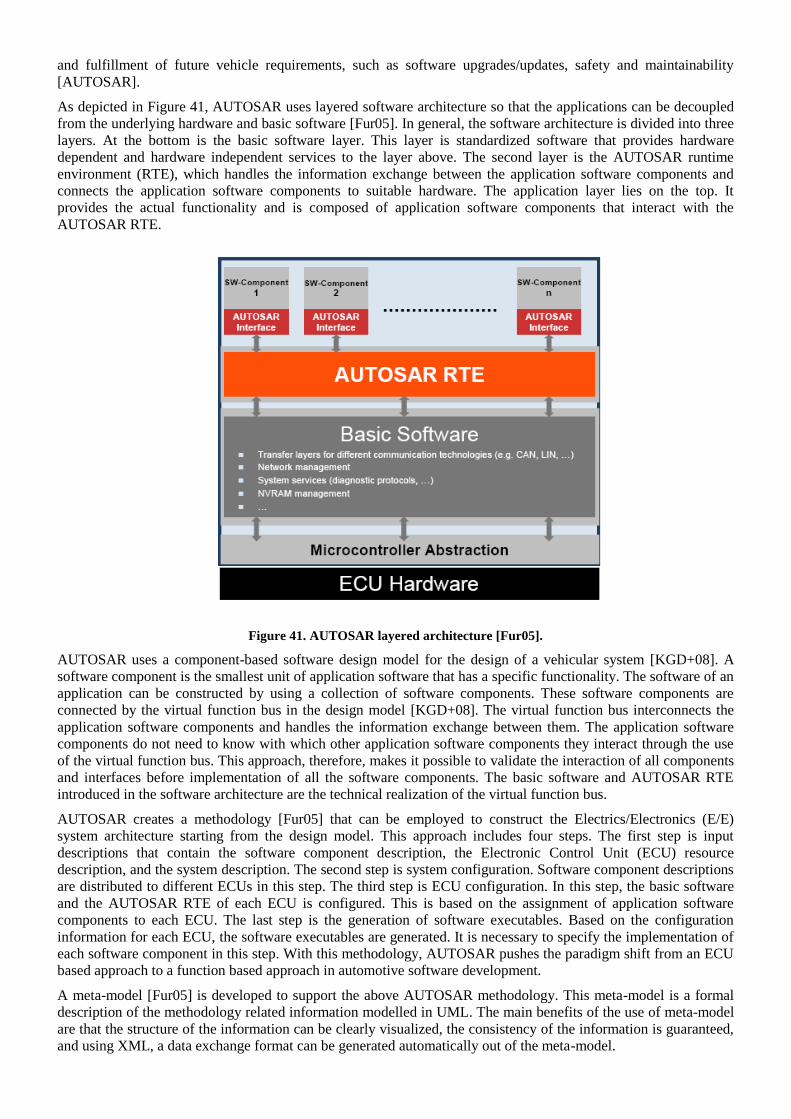
and fulfillment of future vehicle requirements, such as software upgrades/updates, safety and maintainability
[AUTOSAR].
As depicted in Figure 41, AUTOSAR uses layered software architecture so that the applications can be decoupled
from the underlying hardware and basic software [Fur05]. In general, the software architecture is divided into three
layers. At the bottom is the basic software layer. This layer is standardized software that provides hardware
dependent and hardware independent services to the layer above. The second layer is the AUTOSAR runtime
environment (RTE), which handles the information exchange between the application software components and
connects the application software components to suitable hardware. The application layer lies on the top. It
provides the actual functionality and is composed of application software components that interact with the
AUTOSAR RTE.
Figure 41. AUTOSAR layered architecture [Fur05].
AUTOSAR uses a component-based software design model for the design of a vehicular system [KGD+08]. A
software component is the smallest unit of application software that has a specific functionality. The software of an
application can be constructed by using a collection of software components. These software components are
connected by the virtual function bus in the design model [KGD+08]. The virtual function bus interconnects the
application software components and handles the information exchange between them. The application software
components do not need to know with which other application software components they interact through the use
of the virtual function bus. This approach, therefore, makes it possible to validate the interaction of all components
and interfaces before implementation of all the software components. The basic software and AUTOSAR RTE
introduced in the software architecture are the technical realization of the virtual function bus.
AUTOSAR creates a methodology [Fur05] that can be employed to construct the Electrics/Electronics (E/E)
system architecture starting from the design model. This approach includes four steps. The first step is input
descriptions that contain the software component description, the Electronic Control Unit (ECU) resource
description, and the system description. The second step is system configuration. Software component descriptions
are distributed to different ECUs in this step. The third step is ECU configuration. In this step, the basic software
and the AUTOSAR RTE of each ECU is configured. This is based on the assignment of application software
components to each ECU. The last step is the generation of software executables. Based on the configuration
information for each ECU, the software executables are generated. It is necessary to specify the implementation of
each software component in this step. With this methodology, AUTOSAR pushes the paradigm shift from an ECU
based approach to a function based approach in automotive software development.
A meta-model [Fur05] is developed to support the above AUTOSAR methodology. This meta-model is a formal
description of the methodology related information modelled in UML. The main benefits of the use of meta-model
are that the structure of the information can be clearly visualized, the consistency of the information is guaranteed,
and using XML, a data exchange format can be generated automatically out of the meta-model.
To reduce the number of ECUs and to increase the reliability of the overall system, an operating system that
supports the integration of multiple functions within a single ECU is a key technology for the implementation of
AUTOSAR. Such an operating system is called a partitioning operating system [LSO+07] if it can encapsulate
each function in such a way that no interference in the use of ECU's computational resources can occur. The
partitioning operating system needs to prevent interference both in the spatial domain and in the temporal domain.
Spatial partitioning ensures that software in one partition cannot change the software or private data of another
partition. Temporal partitioning ensures that the service received from shared resources by the software in one
partition cannot be affected by the software in another partition.
One example of AUTOSAR-compliant OS is Tresos developed by Elektrobit [AUTOSAR2]. With respect to
spatial partitioning, Tresos uses static allocation of memory to tasks that are protected by Memory Protection Unit
(MPU). AUTOSAR RTE does not support memory protection [LSO+07]. For temporal partitioning, Tresos does
not have strict partitioning due to its use of fixed priority-based preemptive scheduling strategy. Faulty software
components are detected by time monitoring [LSO+07]. As a summary, Tresos focuses on the conformance with
AUTOSAR OS specification that emphasizes backward compatibility and complicated communication middleware
more than partitioning [LSO+07].
References
[Fur05] Fürst S.: AUTOSAR – An open standardized software architecture for the automotive industry. 1st
AUTOSAR open conference & 8th AUTOSAR premium member conference, Detroit, US, Oct.
2005.
[AUTOSAR] http://www.autosar.org [29.03.2011].
[KGD+08] Kinkelin G., Gilberg A., Delord B., Heinecke H., Fürst S., Moessinger J., Lapp A., Virnich U.,
Bunzel S., Weber T., Spinner N., Lundh L., Svensson D., Heitkämper P., Mattsson F., Nishikawa
K., Hirano H., Lange K., Kunkel B.: AUTOSAR on the road. SAE world congress, Detroit, US,
2008.
[LSO+07] Leiner B., Schlager M., Obermaisser R., Huber B.: A comparison of partitioning operating systems
for integrated systems. 26th International conference on computer safety, reliability and security
(SAFECOMP07). Volume 4680 of Lecture Notes in Computer Science., Springer (2007) pages 342-
355.
[AUTOSAR2] http://www.eb-tresos-blog.com/solutions/tresos/ [29.03.2011].
3.2.2 INTEGRATED MODULAR AVIONICS
Integrated Modular Avionics (IMA) is a shared set of flexible, reusable, and inter-operable hardware and software
resources that, when integrated, form a platform that provides services, designed and verified to a defined set of
safety and performance requirements, to host applications performing aircraft functions [IMA].
IMA architectures are based upon a set of modular systems that share a set of computing, communication and I/O
resources. The use of inter-system resources is a new paradigm in the world of system integration. As shown in
Figure 42, the layered architecture of IMA only allows applications to have access to common services via a
defined Application Programming Interface (API) layer [Bla06]. Provided the API layer remains the same,
applications are hardware transparent, which makes it possible to upgrade the underlying hardware or use different
types of hardware without affecting the application software. IMA architectures are described in the context of
traditional federated architectures [Wat06]. In federated system architectures, each avionics system is self-
contained and uses dedicated computing, communication and I/O resources. By contrast, the IMA computing
architecture presents a highly integrated avionics environment. Multiple avionics systems share the IMA platform
resources within a virtual system environment.
The virtual system boundaries are delineated by partitioning mechanisms that are implemented as part of the
platform design. The avionics functions that are hosted on the IMA platform, known as Hosted Functions, can
consist of different design assurance criticalities due to the robust partitioning mechanisms that are inherent to the
IMA architecture. Hosted Functions are allocated to the IMA platform resources to form a functional architecture
specific to each system to meet the availability, operational, safety and topological requirements for each Hosted
Function [Wat06]. Hosted Function can own unique sensors, effectors, devices, etc. which become part of the
functional system architecture. The virtual system partitioning environment guarantees that Hosted Functions are
isolated from each other.

Figure 42. IMA layered design scheme [Bla06].
The platform design guarantees that each Hosted Function has allocated share of the computing, communication
and I/O resources. Operational tools convert the processor, memory needs of each application, together with a
description of the physical architecture of the avionics systems, into a set of tables [Bla06]. These tables are used
by the underlying system infrastructure to allocate and control the physical processor resources, memory and I/O
resource access. Spatial and temporal partitioning coordinates the data flow through the system with the scheduling
of processor resources available to the applications. Data flow, either between a partition and an I/O device, or
between partitions, is handled by the system infrastructure based upon the information stored in the pre-defined
tables.
From the viewpoint of an IMA application, data is available in local memory on the processor card when it is
required, while the data produced by the application is placed in local memory where the software infrastructure
retrieves and transmits it to its destination. With the help of partitioning, IMA's protection mechanism can allow
system resources including memory, processor time, network bandwidth, and file system storage to be shared by
multiple criticality level applications and allow applications to be inserted or altered without impact on the rest of
the system.
IMA's integration process requires the involvement of three kinds of roles [Mad08]. Hosted Function supplier's
responsibility is to develop, test and certify individual applications or subsystems. IMA platform provider is
responsible for developing, testing and certifying IMA platform. Airplane systems integrator is mainly to carry out
the system design, integrate applications and subsystems at system level, and certify the whole system.
The general integration process for avionics in IMA architecture is as follows. Before identifying the avionics
systems, the avionics system interfaces are defined by the IMA platform chosen for the aircraft. This is possible
since the IMA-based interfaces are later configured to meet the specific needs of the hosted avionics systems
[Wat06]. Next, the avionics systems are defined in the context of the shared resources provided by the platform.
The physical IMA platform definition can remain stable while the logical avionics interfaces remain flexible. The
avionics systems are capable of evolving as the aircraft integration process evolves. Finally, future upgrades are
more easily supported for the systems integrator by simply re-running the configuration tools to allocate the
physical platform resources [Wat06]. These tools effectively automate much of the integration process, including
the validation of a modified logical configuration for the integrated avionics. Since the physical platform can
remain unchanged among a modified logical configuration of avionics functions, the existing verification, safety
analysis and aircraft installation remain valid in terms of the physical system. As a summary, IMA moves the
avionics integration activities from the physical domain to the logical domain. This abstracts the avionics system
from much of the physical aircraft-integration work and allows the system integrator to utilize tools to automate
much of the avionics integration process.
References
[IMA] RTCA DO-297 / EUROCAE ED-124, Integrated Modular Avionics (IMA) development guidance
and certification considerations, 2005.
[Wat06] Watkins C.: Integrated modular avionics: Managing the allocation of shared intersystem resources.
25th Digital avionics systems conference, Portland, US, Oct. 2006, pages 1-12.
[Mad08] Madden M.: Integrated modular avionics: Practical aspects of system integration. 27th Digital
avionics systems conference, St. Paul, US, Oct. 2008.
[Bla06] Black R.: Using proven aircraft avionics principles to support a responsive space infrastructure. 4th
Responsive space conference, Los Angeles, US, Apr. 2006.
3.3 PLATFORM REQUIREMENTS
The section gives an overview of the platform assumptions for the component-based software developed using the
notations and tools in the deliverable. The aim is to give the assumptions relied on in order for the model semantics
of the component based software to correspond to the execution semantics on the given platform. There are a
number of assumptions that are commonly relied upon:
The models are correctly implemented. This means we assume translators and compilers generate correct
machine code (semantically equivalent). This is not really a platform issue, but development tool issue.
The processors will execute the program code correctly, i.e., the execution semantics of the program to the
intended semantics of the machine code.
The state of the components is only modified by the instructions in the program. That is, memory
corruption does not occur.
At least these properties are usually needed in order to correctly execute the developed software on the target
platform. In case these properties cannot be assumed, violations need to be detected. Then appropriate measures
are needed to handle the problems. Furthermore, different component based framework might require additional
assumptions about the platforms regarding e.g. scheduling and communication.
3.3.1 EVENT-B
Event-B currently supports two communication paradigms between components: shared events (implemented e.g.
as synchronous message passing or procedure calls) and shared variables. To implement shared event
communication for a concurrent program, a reliable message-passing framework is needed. Blocking reads of
messages is the basic message reception mechanism. For communication between concurrent tasks, messages need
to have guaranteed delivery and the message must not be altered during transmission. To implement shared
variable communication, a framework for shared data (shared memory) between tasks is needed. Furthermore,
events are assumed to be atomic. Hence, adequate synchronisation primitives are needed to ensure that events that
read and modify shared data are actually atomic. In case some of the components involved in the communication
are non-safety critical (NSC), mechanisms to prevent writing outside the shared memory area are needed, together
with mechanisms to prevent deadlocks due to the NSC components not releasing locks.
3.3.2 SIMULINK
The modelling language of Simulink is dataflow language that supports multi-rate models. The code generators for
Simulink support the grouping of blocks with the same rate into concurrent tasks. In order to implement
communication strictly according to the simulation semantics, one need to ensure that blocks handling rate-
conversion have been correctly updated before being read. This means one needs synchronisation primitives such
as monitors with condition variables, semaphores or some other synchronization approach. However, the code
generators also allow relaxation of the communication semantics a little to obtain maximum speed. However, the
simulation semantics is then not necessarily preserved exactly. In a multi-core setting one needs communication
primitives to ensure that the synchronous dataflow semantics is preserved. This can be done using message passing
or shared memory with appropriate synchronisation.
3.3.3 MULTI-CORE PERIODIC RESOURCE (MPR)
The MPR interface framework requires the multi-cores platform to have the following four properties:
Processor cores do not execute instructions out-of-order (although instructions may be executed in parallel,
they must be committed in-order);
Processor cores do not share caches. If caches are shared, then it must be possible to either disable them (as
specified by Req. No. CDR-38-026) or to create core-specific partitions (as specified by Req. No. CDR-
38-064 and CDR-38-079);
Processor cores are identical (homogeneous), in the sense that they have the same computational
capabilities and computing speed;
The platform should enable to bound from above the time needed to perform one read/write transaction to
memory, assuming no contention on the memory bus (as specified by Req. No.: ARR-25-038).
In addition, it is desired (rather than required) that the processor cores perform context switch operations in a time
as short as possible.
3.3.4 ARCHITECTURE ANALYSIS AND DESIGN LANGUAGE
AADL provides runtime mechanisms of exchanging and controlling data by message passing, event passing,
shared memory, remote procedure calls, timing requirements and thread scheduling protocols. These runtime
mechanisms impose certain requirements on platforms to be implemented. For message passing and event passing
mechanisms, consistent and reliable communication channels are required to ensure the integrity of data
transmission. Operating systems are also required to supply services needed to successfully implement timing
requirements and thread scheduling protocols. Shared memory mechanism necessitates some forms of
synchronization primitives such as mutexes, locks or semaphores to prevent data corruption.
3.3.5 UML-MARTE
MARTE (Modelling and Analysis of Real-time and Embedded systems) is a UML profile that adds capabilities to
UML for model-driven development of Real Time and Embedded Systems (RTES). This profile provides support
for specification, design, and verification/validation stages. This new profile is intended to replace the existing
UML Profile for Schedulability, Performance and Time (STP).
The profile is structured around two main concerns, one to model the features of real-time and embedded systems
and the other to annotate application models so as to support analysis of system properties.
As it is based on UML, MARTE allows modelling both structural and behavioural features of the systems, along
with non-functional properties, such as timing, power consumption, etc.
3.3.6 SYSTEMC
The main requirement of our SystemC based component modelling is the usability of an open, FPGA-based, multi-
core platform. An open-source platform is required to allow the possibility of modelling all system components.
Access to the RT-level files is needed to get a stronger knowledge of its internal design to facilitate the modelling
at different level of abstraction. The target technology is programmable logic circuits such as FPGAs to allow this
programmability. Then, any component could be modelled by using SystemC and thus, be replaced by its
equivalent SystemC source code without affecting the entire system. The internal architecture of the FPGA must be
based on multi-core. It must include communications mechanisms such as buses, which must properly described at
RT level or, if possible, implementation files should be available in open formats, so that they can be correctly
modelled at high level design.
3.3.7 AUTOMOTIVE OPEN SYSTEM ARCHITECTURE
AUTOSAR standard contains the definitions of the main features of an OS compliant with it, which include real-
time performance, static configuration combined with a priority-based scheduling strategy and protective functions
for memory and timing during runtime. The AUTOSAR OS standard is based on OSEK/VDX, therefore, it uses
the same fixed priority-based preemptive scheduling strategy for the purpose of compatibility with OSEK. To
protect the data, code and stack section of tasks within an OS-application from other non-trusted OS-applications,
basic memory protection should be fulfilled by the OS. In addition, private data and stack for tasks within the same
OS-application should be protected which requires hardware support in form of an MMU or an MPU. AUTOSAR
Runtime Environment (RTE), which provides communication services among the application software
components, is a communication abstraction layer on top of which software components are running.
3.3.8 INTEGRATED MODULAR AVIONICS
The key characteristics of IMA platform is that system resources are shared by multiple applications. With the help
of partitioning, IMA‘s protection mechanism can allow system resources to be shared by multiple criticality level
applications and allow applications to be inserted or altered without impact on the rest of the system. Temporal
partitioning is provided by using a two-level scheduling scheme. The global scheduler allocates processor time to
partitions according to a static cyclic schedule where each partition runs in turn for the duration of a fixed slice of
time. The local scheduler is priority based. For the spatial partitioning, an MMU is employed for isolating the
partitions from each other. The inter-partition communication is realized via ARINC 653 sampling and queuing
ports.

3.4 CLASSIFICATION OF COMPONENT-BASED FRAMEWORKS To get an overview of the capabilities of the different frameworks above, we have made a table summarising this
information. It can be found in as an appendix in Section 6.2. The classification is done from different
perspectives.
Perspective 1: development phase. There are three categories: System, Software and Hardware. This
indicates which level and for what the framework is useful for. System refers high-level platform
independent models that can be implemented as either hardware or software.
Perspective 2: activity aspects:
o Design activities – This indicates if the framework can be used for creating design models in
contrast to only analysis models.
o Verification activities – Verification refers to the activity of verifying a model/implementation
satisfies its requirements. This can be done via testing or by more formal methods such as model-
checking or various forms of schedulability analysis.
o Safety assessment activities – This refers to safety analysis. Safety analysis is here considered an
activity that is performed early in the development process to find requirements for the system.
Perspective 3: System aspects:
o Behavioural – This refers to functional aspects of the systems
o Timing – This refers to schedulability analysis as well as verification of other timing properties
o Architectural – This refers to the static structure of the system
o Other – The only other aspect considered in the methods above is power consumption
Perspective 4: Model of computation aspects
In addition to the perspectives above, the main strengths and weaknesses of the methods are mentioned. From the
classification sheet one can see that there are tools available for all aspects. However, the selection is fairly limited
for safety analysis.
4 INITIAL PROPOSAL FOR A COMPONENT MODEL IN THE RECOMP PROJECT
The following section makes a proposal for a component model that synthesises elements from the different
models discussed in the previous parts of the deliverable.
Before we can start discussing the specifics of the proposed model we need to take a look at the design flow of a
safety-critical system. The consortium has in this deliverable identified four views of the design flow (sections
1.1.1, 1.2, 1.3 and 3.1.4). The descriptions of these flows or processes are very different, because they have been
described on very different levels of abstraction. For the continued work in the project these flows need to be
described in a more detailed level, however this work will be done in task 2.5 and fully reported in D2.3.1. For the
present report we claim that the processes from 1.1.1, 1.2 and 1.3 can be seen as instances of the AF3 flow
presented in section 3.1.4.
4.1 PLATFORM BASED DESIGN The AF3 (AutoFocus 3) flow is an example of platform-based design [SCB+04], a design flow that uses the
abstraction of platform to guide the design process. Platform-form based design was originally introduced to
facilitate the design of hardware platforms that would be guaranteed to have high-volume production from a single
mask set. The notion was then extended to software platforms, which includes the operating system, and other
API's that would be common over a number of applications [KNR+00]. In RECOMP WP3 is concerned with the
development of the Trusted Multi-Core Platform, thus as an initial effort towards a common RECOMP design
flow, AF3 is a good initial fit.
Recall that system development in AF3 starts with a functional specification of the system behaviour. This
specification is taken to the wanted level of detail, after which the functional components are mapped onto
platform components. This means that one makes architectural decisions about the implementation. The question
of when in the design flow one does the mapping depends on the particulars of the situation. It may well be, that
one can develop the implementation of the functional components quite far, and that the mapping is done just
before the deployment, or the mapping may actually be done quite early in the design phase.

4.2 COMMON COMPONENT META-MODEL The classification table Appendix 6.2 contains a classification of the reviewed component frameworks in the
deliverable. Our first task is to recognize that none of the proposed approaches covers all the aspects of the design
flow, and thus any component model should be a synthesis of the approaches.
The approach taken in the construction of the meta-model is to try to:
Identify a common structure for the component that subsumes the different proposed component
frameworks, and
Identify different aspects that can be covered by the component models
4.3 COMPONENT TYPES
We identify 3 different component "types" that will be needed in the metamodel.
1. Functional components: A component is functional if it describes behaviour in a platform independent
way.
2. Implementation components: An implementation component is a functional component that also contains
information about how it is mapped onto available platform components.
3. Platform components: The exact definition of a platform meta-model will come out of the work of WP3.
For the time being we will define a platform component as a functional component with guarantees.
4.4 COMPONENT META-MODELS
For this deliverable it is important to give an initial description of Functional and Implementation components,
Platform component meta-model will be defined later in the project when the platform definition has moved
forward.
4.5 FUNCTIONAL COMPONENT
Figure 43. Functional Component
Figure 43 shows a class-diagram of the Functional component meta-model. The functional model consists of the
following elements:
1. Services
A service is a single piece of functionality that the component offers to provide to the environment. It consists
of:
1. Interfaces that describe the concrete protocol that needs to be used to access the service.
2. Behaviour, the definition of the semantics of the service.
3. Service level Contracts, that consists of assumptions about the environment, and guarantees that the
component will give under the given assumptions. A real-time requirement of period, execution time
and deadline could partly be seen as a service level contract: under the assumption that the service is
called periodically, the service guarantees that it will execute its behaviour with maximum of the
execution time. Note that the deadline is a component level contract, since it is a guarantee that can
only be given at component level taking into account the other services, and the scheduling policy

2. Ports are access points for Services, sometimes the same port is used to access several service. Ports are
needed in the mapping phase, since they will be translated to concrete communication mechanisms available
on the platform
3. Safety and Certification requirements. These are requirements that are identified, as parts of the Safety Life
Cycle, and/or that are part of the certification process. The methods for modular, compositional construction
of safety cases should be supported by the components as described in Section 3.1.15. This will in turn enable
modular and compositional component-based certification
4. Generic Component level contracts: There may be other component level contracts, constrain the correct use
of the component. For example, a file component has to be used by first opening it before one can read or
write. Such a constraint can be expressed in many different formalisms, but it is a component level contract
because it references individual services of the component (open, read, write).
4.6 ASPECTS
The above discussion does not take into account the differences between the aspects of the component that the
approaches describe. E.g. Event-B can describe behaviour of the system to quite a high-level of detail, while it
does not really deal with time at all. Time can be included in Event-B by adding extra variables, and adding time
keeping into all actions but this is very tedious and the tools do not support explicit reasoning about time. On the
other hand timed I/O automata are highly effective at expressing timing constraints of the system, and come with a
number of tools for analysing such constraints. But doing a full implementation with timed I/O automata is not
really feasible.
We have identified the following aspects from the reviewed approaches:
1. Behaviour aspect: All proposed approaches have a way to describe behaviour. The behavioural
description techniques are characterised by their model of computation. The used models-of-computation
include, State-Based, Sequential, Dataflow, Event-Stream and Flow-based.
2. Time aspect: Time is included in some of the formalisms: e.g. Timed I/O automata, Constant Slope
Automata, and the monitoring concept proposed by TUB.
3. Structure aspect: The structural aspect is used to describe how the components are combined into larger
components. The most capable approach is clearly AADL, which has been developed explicitly for this.
On the other hand e.g. Event-B does not contain explicit support for describing structures in the language.
4. Power aspect: Power or energy consumption has become an important issue for embedded system design,
but little has been done as yet for developing adequate specification techniques. TUB proposes and
approach for power monitoring that constrains the power use of components. Also a version of timed
automata has been used for analysing energy efficiency of systems.
5. Other aspects: Other aspects can be added as needed. Such aspects could be other performance related
aspects, e.g. communication throughput or memory consumption.
4.7 USE OF THE META-MODEL The idea of this meta-model is that it allows us to
1. Discuss about the different approaches using a common vocabulary
2. It allows us to create formalism combinations
4.7.1 EXAMPLE
Let us take a simple example of a counter that has some timing constraints. On the functional level the
behaviour of this counter is described using a combination of Event-B and timed I/O-automata. The Event-B is
given in Figure 44 while the corresponding timed automata is given Figure 5.3.
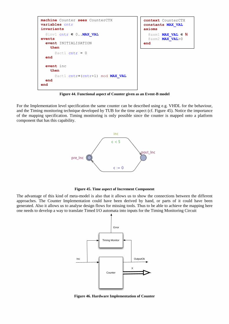
Figure 44. Functional aspect of Counter given as an Event-B model
For the Implementation level specification the same counter can be described using e.g. VHDL for the behaviour,
and the Timing monitoring technique developed by TUB for the time aspect (cf. Figure 45). Notice the importance
of the mapping specification. Timing monitoring is only possible since the counter is mapped onto a platform
component that has this capability.
Figure 45. Time aspect of Increment Component
The advantage of this kind of meta-model is also that it allows us to show the connections between the different
approaches. The Counter Implementation could have been derived by hand, or parts of it could have been
generated. Also it allows us to analyse design flows for missing tools. Thus to be able to achieve the mapping here
one needs to develop a way to translate Timed I/O automata into inputs for the Timing Monitoring Circuit
Figure 46. Hardware Implementation of Counter
Counter
Timing Monitor
Inc OutputOk
Error
X
machine Counter sees CounterCTX
variables cntr
invariants
@inv1 cntr ∈ 0..MAX_VAL events
event INITIALISATION
then
@act1 cntr ≔ 0 end
event inc
then
@act1 cntr≔(cntr+1) mod MAX_VAL end
end
context CounterCTX
constants MAX_VAL
axioms
@axm1 MAX_VAL ∈ ℕ @axm2 MAX_VAL>0
end
References
[KNR+00] K. Keutzer, A. R. Newton, J. M. Rabaey, and A. Sangiovanni-Vincentelli, ―System-level design:
orthogonalization of concerns and platform-based design,‖ IEEE Transactions on Computer-Aided
Design of Integrated Circuits and Systems, vol. 19, no. 12, p. 1523-1543, 2000.
[SCB+04] A. Sangiovanni-Vincentelli, L. Carloni, F. de Bernardinis, and M. Sgroi, ―Benefits and challenges
for platform-based design,‖ Design Automation Conference, 2004. Proceedings. 41st, p. 409-414,
2004.
5 CONCLUSION AND FUTURE WORK IN WP2 The deliverable is an attempt to give an overview of the different obstacles in the different domains of RECOMP
for component-based development of mixed criticality systems that run on multi-core systems and how they can be
overcome. The basic assumption is that component-based development is beneficial for development of systems of
the type above. Different component frameworks for design and analysis have been presented and their usefulness
assessed. Furthermore, we also state what platform requirements they rely on in order to provide suggestions to
WP3 on e.g. the types of communication primitives that would be needed to support systems built using the
presented component frameworks. We have sketched an initial component model specification suitable for the
development of safety critical systems. We also discuss how we envision that different state-of-the-art modelling
and analysis tools can be utilised in this setting. It is not realistic to assume we can only have one component
model, but probably several component models tailored to different development process for different domains are
needed. The proposed component model specification outlines what is required from a component model, in order
to be used in developing safety-critical systems.
We envision that components are modelled using different notations from different perspectives. Future work in
WP2 includes development of concrete component models integrated in tools that support this approach. From a
verification point of view there are several challenges to be solved in Task 2.2 and Task 2.3. As we envision that
components can be modelled from different perspectives, we need to verify that the descriptions of different
aspects are consistent. Different tools are needed for unit verification of components with respect to the
specifications covering the different component aspects. To verify component-based systems we need methods to
reason about component composition one aspect at the time. The overall goal is cost-effective verification and
validation for the purpose of certification of component-based systems. Furthermore, it would be interesting to
investigate the opportunity to perform ―modular certification‖. This requires, apart from adequate verification and
validation methods of the component based systems, also modular and compositional building of safety cases.
6 APPENDIX
6.1 THE DANFOSS CASE STUDY – REQUIREMENTS The below requirements are an extract from the requirements management system for the Danfoss case study.
1 OBSOLETE REQUIREMENTS (WHAT57697) ID: WHAT57697 Version: 1.0 Status: Draft
1.1 POWER CYCLE (WHAT57698) ID: WHAT57698 Version: 1.0 Status: Obsolete
All active safety functions shall be remembered in case of a power cycle.
2 GENERIC SAFETY REQUIREMENTS (WHAT57699) ID: WHAT57699 Version: 2.0 Status: Draft
Requirements for the case study are listed below.

EMC and environmental requirements have been removed.
2.1 SAFETY FUNCTIONS (WHAT57778) ID: WHAT57778 Version: 1.0 Status: Draft
2.1.1 STANDARDS TO BE FULFILLED (WHAT57779) ID: WHAT57779 Version: 1.0 Status: Draft
2.1.1.1 IEC 61508 (WHAT57780) ID: WHAT57780 Version: 2.0 Status: Draft
The integrated safety functions of the drive shall fulfil IEC 61508.
2.1.1.2 IEC 61800-5-2 (WHAT57781) ID: WHAT57781 Version: 2.0 Status: Draft
The integrated safety functions of the drive shall fulfil IEC 61800-5-2.
2.1.1.3 ISO 13849-1 (WHAT57782) ID: WHAT57782 Version: 2.0 Status: Draft
The integrated safety functions of the drive shall fulfil ISO 13849-1.
2.1.1.4 IEC 62061 (WHAT57783) ID: WHAT57783 Version: 2.0 Status: Draft
The integrated safety functions of the drive shall fulfil IEC 62061.
2.1.1.5 FAULT EXCLUSIONS (WHAT57784) ID: WHAT57784 Version: 2.0 Status: Draft
Fault exclusions from ISO 13849-2 or IEC 61800-5-2 may be used. All fault exclusions used have to be
documented.
Note: Fault exclusions are used to rule out certain faults, e.g. because x is applied, fault y will never occur.
2.1.2 COMMON SAFETY FUNCTION REQUIREMENTS (WHAT57785)
ID: WHAT57785 Version: 1.0 Status: Draft
2.1.2.1 FAILURE REACTION TIME (WHAT57786) ID: WHAT57786 Version: 1.0 Status: Draft
Acceptable failure reaction time has to be decided on during development.
2.1.2.2 START UP (WHAT57787) ID: WHAT57787 Version: 2.0 Status: Draft
The system shall start up in safe state until all internal diagnostics have shown that the safety related circuits work
as intended and that the safety function is not enabled through the user terminals.
2.1.2.3 SHUT DOWN (WHAT57788) ID: WHAT57788 Version: 2.0 Status: Draft
The system has to be in safe state during shut down or it has to be possible to activate the safety function during
shutdown.
2.1.2.4 PROOF TEST (WHAT57789) ID: WHAT57789 Version: 2.0 Status: Draft
A proof test shall not be necessary. All diagnostic measures shall be implemented as online diagnostics.
Note: A Proof test is applied, if some diagnostic techniques and measures are only executed at start-up of the
system.
2.1.2.5 LIFETIME (WHAT57790) ID: WHAT57790 Version: 1.0 Status: Draft
The lifetime of the integrated safety functions shall be 20 years.
2.1.3 REQUIREMENTS FOR SAFE TORQUE OFF (STO) (WHAT57791)
ID: WHAT57791 Version: 1.0 Status: Draft
2.1.3.1 DESCRIPTION OF THE FUNCTION (WHAT57792) ID: WHAT57792 Version: 1.0 Status: Draft
On activation of STO, the redundant output shall be set to LOW (0V)
2.1.3.2 SAFETY INTEGRITY LEVEL (SIL) (WHAT57793) ID: WHAT57793 Version: 1.0 Status: Draft
SIL 3 according to IEC 61508 and IEC 61800-5-2 shall be fulfilled.
2.1.3.3 CATEGORY (WHAT57794) ID: WHAT57794 Version: 1.0 Status: Draft
Category 4 according to ISO 13849-1 shall be fulfilled.
2.1.3.4 PERFORMANCE LEVEL (PL) (WHAT57795) ID: WHAT57795 Version: 1.0 Status: Draft
PL e according to ISO 13849-1 shall be fulfilled.
2.1.3.5 HARDWARE FAULT TOLERANCE (HFT) (WHAT57796) ID: WHAT57796 Version: 1.0 Status: Draft
HFT of 1 shall be implemented.
2.1.3.6 SAFE FAILURE FRACTION (SFF) (WHAT57797) ID: WHAT57797 Version: 1.0 Status: Draft
A SFF of 90 % shall be achieved.
2.1.3.7 PROBABILITY OF FAILURE PER HOUR (PFH) (WHAT57798)
ID: WHAT57798 Version: 2.0 Status: Draft
A PFH of < 10 fit1 shall be achieved. 1 failure in time (http://en.wikipedia.org/wiki/failures_in_time)

Note: Failure In Time (http://en.wikipedia.org/wiki/Failures_in_time)
2.1.3.8 MEAN TIME TO FAILURE DANGEROUS (MTTFD) (WHAT57799)
ID: WHAT57799 Version: 1.0 Status: Draft
MTTFd > 100 years shall be achieved.
2.1.3.9 DIAGNOSTIC COVERAGE (DC) (WHAT57800) ID: WHAT57800 Version: 1.0 Status: Draft
A DC of minimum 90 % shall be achieved for complex electronic parts. For non-complex parts a DC that is
sufficient to achieve the needed SFF shall be achieved.
2.1.3.10 SAFE STATE (WHAT57801) ID: WHAT57801 Version: 1.0 Status: Draft
Safe state is STO activated.
2.1.3.11 FAIL SAFE STATE (WHAT57802) ID: WHAT57802 Version: 1.0 Status: Draft
Each state where no torque on the motor can be generated is considered as a fail safe state.
2.1.3.12 REACTION TIME (WHAT57803) ID: WHAT57803 Version: 1.0 Status: Draft
The reaction time from user terminal to active STO shall be less than 10 ms.
2.1.4 REQUIREMENTS FOR SAFE STOP 1 (SS1) DELAY (WHAT57804)
ID: WHAT57804 Version: 1.0 Status: Draft
2.1.4.1 DESCRIPTION OF THE FUNCTION (WHAT57805) ID: WHAT57805 Version: 1.0 Status: Draft
On activation of SS1, a timer with a configurable delay shall be started and the frequency converter is requested to
start a non-safe ramp down. After the timer expires, the STO function shall be activated.
2.1.4.2 SAFETY INTEGRITY LEVEL (SIL) (WHAT57806) ID: WHAT57806 Version: 1.0 Status: Draft
SIL 3 according to IEC 61508 and IEC 61800-5-2 shall be fulfilled.
2.1.4.3 CATEGORY (WHAT57807) ID: WHAT57807 Version: 1.0 Status: Draft
Category 4 according to ISO 13849-1 shall be fulfilled.
2.1.4.4 PERFORMANCE LEVEL (PL) (WHAT57808) ID: WHAT57808 Version: 1.0 Status: Draft
PL e according to ISO 13849-1 shall be fulfilled.
2.1.4.5 HARDWARE FAULT TOLERANCE (HFT) (WHAT57809) ID: WHAT57809 Version: 1.0 Status: Draft
HFT of 1 shall be implemented.
2.1.4.6 SAFE FAILURE FRACTION (SFF) (WHAT57810) ID: WHAT57810 Version: 1.0 Status: Draft
A SFF of 90 % shall be achieved.
2.1.4.7 PROBABILITY OF FAILURE PER HOUR (PFH) (WHAT57811)
ID: WHAT57811 Version: 1.0 Status: Draft
A PFH of < 10 fit shall be achieved.
2.1.4.8 MEAN TIME TO FAILURE DANGEROUS (MTTFD) (WHAT57812)
ID: WHAT57812 Version: 1.0 Status: Draft
MTTFd > 100 years shall be achieved.
2.1.4.9 DIAGNOSTIC COVERAGE (DC) (WHAT57813) ID: WHAT57813 Version: 1.0 Status: Draft
A DC of minimum 90 % shall be achieved for complex electronic parts. For non-complex parts a DC that is
sufficient to achieve the needed SFF shall be achieved.
2.1.4.10 SAFE STATE (WHAT57814) ID: WHAT57814 Version: 1.0 Status: Draft
Safe state is STO activated.
2.1.4.11 FAIL SAFE STATE (WHAT57815) ID: WHAT57815 Version: 1.0 Status: Draft
Each state where no torque on the motor can be generated is considered as a fail safe state.
2.1.4.12 REACTION TIME (WHAT57816) ID: WHAT57816 Version: 1.0 Status: Draft
The reaction time from user terminal to active SS1 shall be less than 10 ms.
2.1.5 SAFE FIELD BUS (WHAT57817) ID: WHAT57817 Version: 1.0 Status: Draft
2.1.5.1 DESCRIPTION OF FUNCTION (WHAT57818) ID: WHAT57818 Version: 1.0 Status: Draft
It shall be possible to activate all safety functions using a safe field bus.
2.1.5.2 SAFETY INTEGRITY LEVEL (SIL) (WHAT57819) ID: WHAT57819 Version: 1.0 Status: Draft
SIL 3 according to IEC 61508 and IEC 61800-5-2 shall be fulfilled.
2.1.5.3 CATEGORY (WHAT57820) ID: WHAT57820 Version: 1.0 Status: Draft
Category 4 according to ISO 13849-1 shall be fulfilled.

2.1.5.4 PERFORMANCE LEVEL (PL) (WHAT57821) ID: WHAT57821 Version: 1.0 Status: Draft
PL e according to ISO 13849-1 shall be fulfilled.
2.1.5.5 HARDWARE FAULT TOLERANCE (HFT) (WHAT57822) ID: WHAT57822 Version: 1.0 Status: Draft
HFT of 1 shall be implemented.
2.1.5.6 SAFE FAILURE FRACTION (SFF) (WHAT57823) ID: WHAT57823 Version: 1.0 Status: Draft
A SFF of 90 % shall be achieved.
2.1.5.7 PROBABILITY OF FAILURE PER HOUR (PFH) (WHAT57824)
ID: WHAT57824 Version: 1.0 Status: Draft
Residual failure rate for transmission < 1 % of pfh of sil 3.
2.1.5.8 MEAN TIME TO FAILURE DANGEROUS (MTTFD) (WHAT57825)
ID: WHAT57825 Version: 1.0 Status: Draft
To be calculated together with assigned safety function.
2.1.5.9 DIAGNOSTIC COVERAGE (DC) (WHAT57826) ID: WHAT57826 Version: 1.0 Status: Draft
A DC of minimum 90 % shall be achieved for complex electronic parts. For non-complex parts a DC that is
sufficient to achieve the needed SFF shall be achieved.
2.1.5.10 SAFE STATE (WHAT57827) ID: WHAT57827 Version: 1.0 Status: Draft
Bus transmission stopped or transmission of safe state signal.
2.1.5.11 FAIL SAFE STATE (WHAT57828) ID: WHAT57828 Version: 1.0 Status: Draft
Each state that leads to interruption of transmission.
2.1.5.12 REACTION TIME (WHAT57829) ID: WHAT57829 Version: 1.0 Status: Draft
Depending on field bus used.
2.1.5.13 FAILURE REACTION TIME (WHAT57830) ID: WHAT57830 Version: 1.0 Status: Draft
Depending on field bus used.
2.1.6 INTERFACES (WHAT57831) ID: WHAT57831 Version: 1.0 Status: Draft
2.1.6.1 SAFE INPUTS (WHAT57832) ID: WHAT57832 Version: 1.0 Status: Draft
2.1.6.1.1 REDUNDANT NORMALLY CLOSED INPUT (WHAT57833)
ID: WHAT57833 Version: 1.0 Status: Draft
It shall be possible to connect a redundant 24 V safe input signal. Safety function is activated if at least one input is
open. Safety function is deactivated if both inputs are +24 V.
2.1.6.1.2 REDUNDANT NORMALLY CLOSED - NORMALLY OPEN INPUT (WHAT57834)
ID: WHAT57834 Version: 1.0 Status: Draft
It shall be possible to connect safe input signals that are normally closed - normally open. For activation of the
safety function at least one input has to change state (+24 V to open or open to +24 V).
2.1.6.1.3 REDUNDANT +24 V – GND INPUT (WHAT57835) ID: WHAT57835 Version: 1.0 Status: Draft
It shall be possible to connect safe input signals where one signal switches GND and the other switches +24 V. For
activation of safety function at least one input has to change state (+24 V to open or GND to open).
2.1.6.1.4 PULSED INPUT SIGNALS LENGTH (WHAT57836) ID: WHAT57836 Version: 1.0 Status: Draft
The safety function shall not be activated on pulses shorter than or equal to 3 ms.
2.1.6.1.5 PULSED INPUT SIGNALS REPETITION RATE (WHAT57837)
ID: WHAT57837 Version: 4.0 Status: Draft
The safety function shall not be activated if the pulses on the inputs appear every 100 ms.
Pulses with a repetition rate <100ms may activate the safety function, but it is preferred not to activate it.
Pulses with a repetition rate >=100ms shall not activate the safety function.
2.1.6.1.6 DIAGNOSTIC (WHAT57838) ID: WHAT57838 Version: 1.0 Status: Draft
For diagnostic purpose it shall be possible to pulse the input signal.
2.1.6.1.7 CONFIGURABLE (WHAT57839) ID: WHAT57839 Version: 1.0 Status: Draft
It shall be configurable, which safety function is associated with the inputs.
2.1.6.2 SAFE OUTPUTS (WHAT57840) ID: WHAT57840 Version: 1.0 Status: Draft
2.1.6.2.1 REDUNDANT OUTPUT (WHAT57841) ID: WHAT57841 Version: 1.0 Status: Draft
The redundant output is used to independently activate the safe state of the frequency converter.

2.1.6.2.2 DIAGNOSTIC (WHAT57842) ID: WHAT57842 Version: 1.0 Status: Draft
For diagnostic purpose it shall be possible to pulse the safe outputs. The diagnostic pulse shall be triggered each
second, with a pulse width of less than or equal to 300 microseconds.
2.1.6.2.2.1 ASYNCHRONOUS DIAGNOSTIC (WHAT57843) ID: WHAT57843 Version: 1.0 Status: Draft
The outputs shall be diagnosed asynchronously in order to detect short circuits between them.
2.1.6.3 STATUS OUTPUT (WHAT57844) ID: WHAT57844 Version: 1.0 Status: Draft
It shall be possible to get the status of the safety function(s) through an output signal.
2.1.6.4 RESET SIGNAL (WHAT57845) ID: WHAT57845 Version: 1.0 Status: Draft
2.1.6.4.1 DIFFERENT SOURCES (WHAT57846) ID: WHAT57846 Version: 1.0 Status: Draft
2.1.6.4.1.1 DEDICATED INPUT (WHAT57847) ID: WHAT57847 Version: 2.0 Status: Draft
It shall be possible to reset the system via a standard input after deactivation of a safety function.
2.1.6.4.1.2 FIELD BUS (WHAT57848) ID: WHAT57848 Version: 3.0 Status: Draft
It shall be possible to reset the system via the field bus after deactivation of a safety function.
2.1.6.4.1.3 CONFIGURABLE (WHAT57849) ID: WHAT57849 Version: 1.0 Status: Draft
It shall be configurable which reset source is used.
2.1.6.5 RESET NEEDED (WHAT57850) ID: WHAT57850 Version: 1.0 Status: Draft
2.1.6.5.1 AFTER DEACTIVATION OF SAFETY FUNCTION (WHAT57851)
ID: WHAT57851 Version: 1.0 Status: Draft
It shall be configurable whether a reset is needed after deactivation of safety function or not.
2.1.6.5.2 AFTER CUSTOMIZATION (WHAT57852) ID: WHAT57852 Version: 1.0 Status: Draft
The drive shall require a reset after customization of safety relevant parameters.

2.1.6.5.3 AFTER POWER UP (WHAT57853) ID: WHAT57853 Version: 1.0 Status: Draft
It shall be configurable whether a reset is needed after power up.
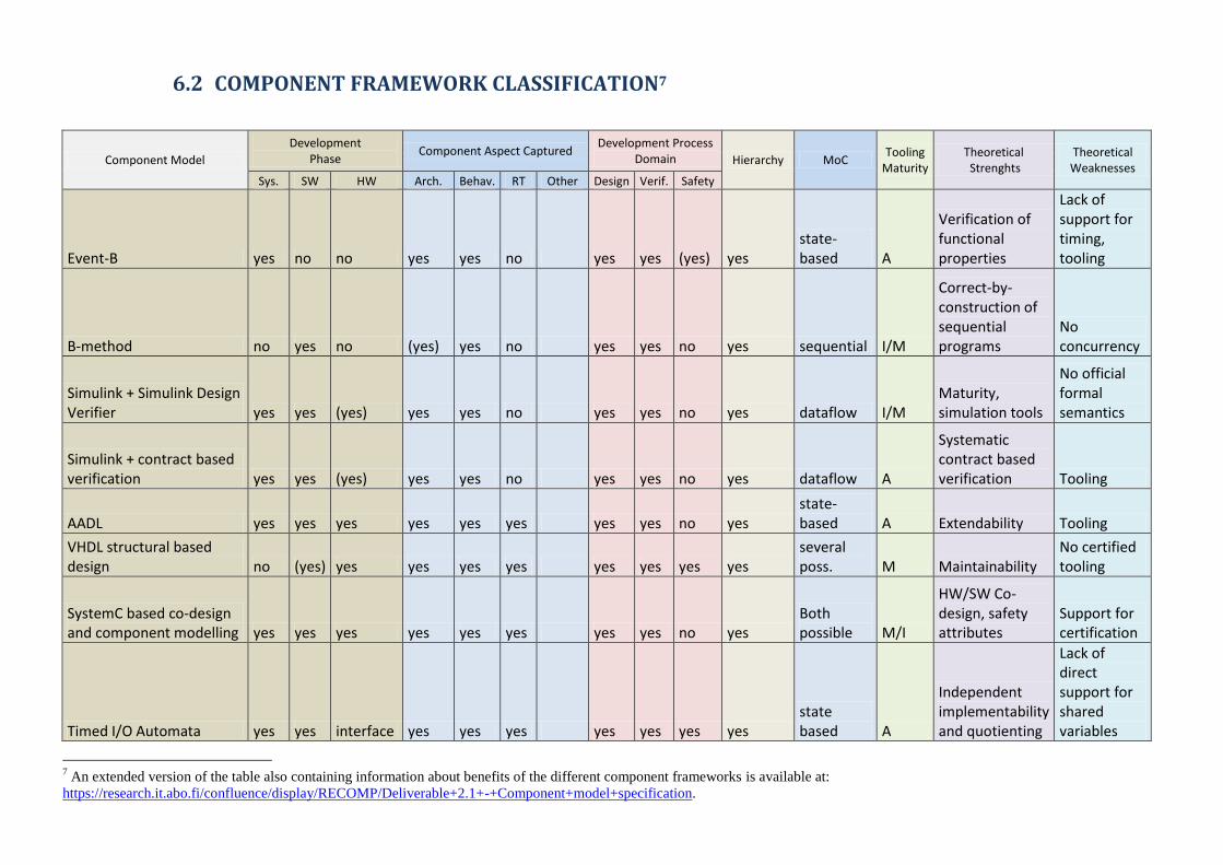
6.2 COMPONENT FRAMEWORK CLASSIFICATION7
Component Model
Development Phase
Component Aspect Captured Development Process
Domain Hierarchy MoC Tooling
Maturity Theoretical Strenghts
Theoretical Weaknesses
Sys. SW HW Arch. Behav. RT Other Design Verif. Safety
Event-B yes no no yes yes no yes yes (yes) yes state-based A
Verification of functional properties
Lack of support for timing, tooling
B-method no yes no (yes) yes no yes yes no yes sequential I/M
Correct-by-construction of sequential programs
No concurrency
Simulink + Simulink Design Verifier yes yes (yes) yes yes no yes yes no yes dataflow I/M
Maturity, simulation tools
No official formal semantics
Simulink + contract based verification yes yes (yes) yes yes no yes yes no yes dataflow A
Systematic contract based verification Tooling
AADL yes yes yes yes yes yes yes yes no yes state-based A Extendability Tooling
VHDL structural based design no (yes) yes yes yes yes yes yes yes yes
several poss. M Maintainability
No certified tooling
SystemC based co-design and component modelling yes yes yes yes yes yes yes yes no yes
Both possible M/I
HW/SW Co-design, safety attributes
Support for certification
Timed I/O Automata yes yes interface yes yes yes yes yes yes yes state based A
Independent implementability and quotienting
Lack of direct support for shared variables
7 An extended version of the table also containing information about benefits of the different component frameworks is available at:
https://research.it.abo.fi/confluence/display/RECOMP/Deliverable+2.1+-+Component+model+specification.

Constant Slope Timed Automata yes yes interface yes yes yes yes yes yes no
state based A Scalability
Trace explostion problem
Event-based timing model yes no no no no yes yes yes no (yes) event-stream T
fine-grained analysis, formal
Complexity for large systems
Event-based power model yes no no no no no power yes yes no yes event-stream T
Reuse of existing methods
accuracy vs. HW overhead
AutoFOCUS3 yes yes yes yes yes yes yes no no yes flow based A
Resource and timing analysis (MPR) yes no no no no yes no yes no yes task-based A
Used for modelling timing reqs. in ARINC-653, Temporal isolation of components
Overhead due to to two level scheduling hierarchy
Time-constrained automata yes yes no yes yes yes yes yes yes no
state-based M/I
Combining expressivity and exact automatic analyses
Refinement from high-level design and hierarchy are only WiP
UML-MARTE yes yes yes yes yes yes yes yes (yes) yes several poss. M
Extendability, adaptability
Need support by a methodology
AUTOSAR yes yes yes yes no no yes no no yes N/A M Component based systems
Lack of timing analysis, resource consumption
IMA yes yes yes yes no yes yes no yes yes N/A M Protection mechanisms
Does not consider component coordination