redPOWER 300W to 2.0kW Module Fiber Lasers Instructions ... · 7.8 Connecting the PIPA-Q Optical...
94
redPOWER PRISM 300W to 2.0kW Fiber Lasers Instructions for Use
Transcript of redPOWER 300W to 2.0kW Module Fiber Lasers Instructions ... · 7.8 Connecting the PIPA-Q Optical...
redPOWER PRISM
300W to 2.0kW Fiber Lasers
Instructions for Use
© 2017 SPI Lasers UK Ltd.
Commercial in Confidence
SM-S00481 Revision F 02 August 2017
redPOWER 300W to 2.0kW Module Fiber Lasers
Instructions for Use
2
Safety Notes These safety notes indicate potential hazards associated with this PRISM Fiber Laser and the
probable consequences of not avoiding them. Directions on the safe use of this Laser are
provided in the remainder of these instructions for use, particularly Sections 3 Health and
Safety, 7 Installation, and 8 Operating Instructions.
Throughout these Instructions for Use warning messages are given in contexts in which a
hazard may occur.
General Hazard Information
WARNING: Ensure that all Users are fully aware of all safety
implications identified in these Instructions for Use before
attempting to install, operate or maintain this Laser.
WARNING: Attempts to modify or alter this PRISM Fiber Laser or
the use of controls or adjustments or performance of procedures
other than those specified in these Instructions for Use may render
this Laser unsafe.
Attempts to modify or alter this Laser or the use of controls or adjustments or performance of
procedures other than those specified in these Instructions for Use additionally will invalidate
the warranty and may result in patent infringement.
Laser Integrators are not authorised to modify this Laser.
© 2017 SPI Lasers UK Ltd.
Commercial in Confidence
SM-S00481 Revision F 02 August 2017
redPOWER 300W to 2.0kW Module Fiber Lasers
Instructions for Use
3
Laser Hazard Information
WARNING: The output aperture of this PRISM Fiber Laser may
emit both invisible and visible laser radiation.
The invisible laser radiation will be Class 4 laser radiation. The
invisible radiation can be up to approximately 115% of rated power
CW in normal operation and 150% with a single fault. The
wavelength of this invisible radiation is in the range 1050-1250nm.
Additionally, this Laser contains embedded lasers that emit invisible
laser radiation up to approximately 170% of rated power CW in
normal operation and 250% CW with a single fault. The wavelength
of this invisible radiation is in the range 900-1000nm.
AVOID EYE OR SKIN EXPOSURE TO DIRECT OR SCATTERED
RADIATION.
Contact with direct or scattered laser radiation can cause damage
to the eyes, burn human tissue and start fires.
The optical connector shall be mounted in a protective housing
which prevents human access to laser radiation (including errant
radiation) in excess of the AEL for class 1, for example a housing
meeting the requirements of EN 60825-4.
WARNING: The output aperture of this PRISM Fiber Laser may
emit both invisible and visible laser radiation.
The visible laser radiation is below the Accessible Emission Limit
(AEL) for a Class 2 laser. The wavelength of the visible laser
radiation is in the range 630 – 680nm.
DO NOT STARE INTO BEAM.
WARNING: This PRISM Fiber Laser must only be operated when
the optical connector is mounted in an appropriate receiver.
Care must be taken to prevent the electrical contacts on the optical
connector being accidentally connected. Do not place the optical
connector on a metal surface.
The protective cap must be placed over the connector whenever
the connector is not in a receiver.
WARNING: Before carrying out any maintenance task detailed in
these Instructions for Use ensure that power to the Laser is
disconnected. Failure to do so may lead to serious personal injury.
© 2017 SPI Lasers UK Ltd.
Commercial in Confidence
SM-S00481 Revision F 02 August 2017
redPOWER 300W to 2.0kW Module Fiber Lasers
Instructions for Use
4
WARNING: This PRISM Fiber Laser does not control the pump
power supply and has no safety function to de-energise or control
the pump diodes or the output power.
Failure to provide external safety systems may result in exposure to
harmful levels of radiation.
Electrical Hazard Information
CAUTION: This PRISM Fiber Laser must be grounded for safety
and to comply with regional electrical codes.
Failure to do so may result in electric shock and incorrect operation
of the Laser.
Weight Hazard Information
CAUTION: This PRISM Fiber Laser is heavy and so precautions
must be taken when lifting and moving.
Failure to do so may cause serious injury.
Pressure Hazard Information
CAUTION: Ensure an approved overpressure safety device
compliant with ISO4126-1 (or equivalent) is installed when
connecting the PRISM Fiber Laser to an external chiller or factory
water supply.
Failure to do so may result in water leaks and damage to the Laser
and auxiliary equipment.
Laser for Incorporation
CAUTION: This PRISM Fiber Laser is specifically designed to be a
laser for incorporation or integration into other equipment. As such,
it is not required to, and does not, meet the requirements for a
stand-alone laser system as defined by IEC/EN 60825-1.

© 2017 SPI Lasers UK Ltd.
Commercial in Confidence
SM-S00481 Revision F 02 August 2017
redPOWER 300W to 2.0kW Module Fiber Lasers
Instructions for Use
5
CONTENTS 1 Structure and Scope of these Instructions for Use 9
2 Definition of Symbols and Terms 10
3 Health and Safety 12
3.1 General 12 3.2 Intended Use of the PRISM Fiber Laser 12 3.3 Hazards 13 3.4 Compliance 14 3.5 Labelling 17
4 Document References 19
5 redPOWER PRISM Tour 20
5.1 Key Parts 21 5.2 Key Features 21 5.3 Auxiliary Equipment 25 5.4 Software Tools 26 5.5 Explanation of Order Codes 27
6 Getting Started 29
6.1 Receiving and Inspection 29 6.2 Unpacking and Handling 29 6.3 Unpacking the Beam Delivery Optic 33
7 Installation 34
7.1 Safety and Compliance During Installation 34 7.2 Location and Environment 34 7.3 Mounting 35 7.4 PRISM Fiber Lasers with Bare Fiber Output 35 7.5 Cooling Water Connections 35 7.6 Electrical Connections 39 7.7 Routing the Beam Delivery Optic 49 7.8 Connecting the PIPA-Q Optical Connector to the Process Head 51 7.9 Removing PIPA-Q Optical Connector from the Process Head 54
8 Operating Instructions 55
8.1 Before Operation 55 8.2 Modes of Operation 56 8.3 Turning the Laser On and Off 58 8.4 Turning the Alignment Laser On and Off 62 8.5 Monitoring, Alarms and Diagnostics 62 8.6 Laser Control Using PrismView 65 8.7 Serial Control of the Laser 65
© 2017 SPI Lasers UK Ltd.
Commercial in Confidence
SM-S00481 Revision F 02 August 2017
redPOWER 300W to 2.0kW Module Fiber Lasers
Instructions for Use
6
9 Maintenance 66
9.1 Periodic Inspection 66 9.2 General Cleaning 66 9.3 Maintenance of Optics 67
10 Disposal 72
11 Specifications 73
11.1 Operating Conditions 73 11.2 Non-Operating Conditions 75 11.3 Utility Requirements 75 11.4 Optical Specifications 80 11.5 Mechanical Specifications 83
12 General Information 91
12.1 Trade Marks 91 12.2 Licensing 91 12.3 Software 91 12.4 Warranties 91 12.5 Copyright 91 12.6 Changes 92
13 Contact Information 93
14 Customer Service 94
FIGURES Figure 1 WEEE Symbol ........................................................................................................................... 14
Figure 2 PRISM Fiber Laser with Optical Connector Key Parts .............................................................. 21
Figure 3 PRISM Fiber Laser Key Features ............................................................................................. 22
Figure 4 PIPA-Q Optical Connector with Protection Against Back-Reflection ........................................ 24
Figure 5 PRISM Fiber Laser with Auxiliary Equipment ........................................................................... 26
Figure 6 Laser in Crate as Received ....................................................................................................... 29
Figure 7 Removing Fastener ................................................................................................................... 30
Figure 8 Crate without Lid and Top Layer of Foam Packaging ............................................................... 31
Figure 9 Lift BDO to Enable the Next Layer of Packaging to be Removed ............................................ 31
Figure 10 BDO Replaced ........................................................................................................................ 32
Figure 11 Lifting Laser from Crate ........................................................................................................... 33
Figure 12 Cooling Water Connections .................................................................................................... 36

© 2017 SPI Lasers UK Ltd.
Commercial in Confidence
SM-S00481 Revision F 02 August 2017
redPOWER 300W to 2.0kW Module Fiber Lasers
Instructions for Use
7
Figure 13 Electrical Connections and Status Indicators .......................................................................... 40
Figure 14 Star Earthing Configuration ..................................................................................................... 41
Figure 15 Bus Bar Connection ................................................................................................................ 42
Figure 16 User Interface Connector ........................................................................................................ 43
Figure 17 PLC Logic Levels .................................................................................................................... 44
Figure 18 TTL Logic Levels ..................................................................................................................... 44
Figure 19 RS-232 and RS-485 Connector .............................................................................................. 48
Figure 20 PIPA-Q with Protective Cap .................................................................................................... 52
Figure 21 Connector Before Removal of Protective Tape ...................................................................... 52
Figure 22 Red Dots Aligned .................................................................................................................... 53
Figure 23 Connector Inserted into Receiver ............................................................................................ 53
Figure 24 Timing Diagram for CW Operation .......................................................................................... 59
Figure 25 Timing Diagram for Operation in Analogue Modulation Mode ................................................ 60
Figure 26 Timing Diagram for Operation in Digital Modulation Mode ..................................................... 61
Figure 27 PIPA-Q Window Assembly ...................................................................................................... 68
Figure 28 Removing Sleeve .................................................................................................................... 69
Figure 29 Placing Lens Cleaning Paper on top of the Window ............................................................... 69
Figure 30 Wetting the Lens Paper ........................................................................................................... 70
Figure 31 Cleaning the Window .............................................................................................................. 70
Figure 32 Removing Window .................................................................................................................. 71
Figure 33 Environmental Conditions for Non-Condensing Operation ..................................................... 74
Figure 34 Minimum Flow Rate against Inlet Water Temperature ............................................................ 79
Figure 35 Modulation Bandwidth as a Function of Set Power ................................................................ 81
Figure 36 Outline Drawing – Short Module ............................................................................................. 84
Figure 37 Mounting Locations – Short Module ........................................................................................ 85
Figure 38 Outline Drawing – Long Module .............................................................................................. 86
Figure 39 Mounting Locations – Long Module ........................................................................................ 87
Figure 40 PIPA-Q Optical connector ....................................................................................................... 87
Figure 41 Outline Drawing – PIPA-Q Beam Delivery Optic .................................................................... 88
Figure 42 Outline Drawing – Bare Fiber Output ...................................................................................... 89

© 2017 SPI Lasers UK Ltd.
Commercial in Confidence
SM-S00481 Revision F 02 August 2017
redPOWER 300W to 2.0kW Module Fiber Lasers
Instructions for Use
8
TABLES Table 1 Safety, Explanatory and Compliance Labels ............................................................................. 17
Table 2 Information Labels ...................................................................................................................... 18
Table 3 Explanation of Order Code ......................................................................................................... 27
Table 4 Water Tubing and Fittings .......................................................................................................... 37
Table 5 Electrical Interface Connections ................................................................................................. 40
Table 6 Pinout of User Interface Connector ............................................................................................ 45
Table 7 RS-232 and RS-485 Control ...................................................................................................... 48
Table 8 Meaning of Status Words ........................................................................................................... 62
Table 9 Replacement Window Kit and Replacement Window ................................................................ 67
Table 10 Environmental Operating Conditions........................................................................................ 73
Table 11 Non-Operating Conditions ........................................................................................................ 75
Table 12 Electrical Requirements ........................................................................................................... 75
Table 13 Power Supply Output Capability Requirements ....................................................................... 76
Table 14 Cooling Water Requirements ................................................................................................... 77
Table 15 Cooling Requirements (Base Plate) ......................................................................................... 78
Table 16 Required Chiller Capacity ......................................................................................................... 79
Table 17 Cooling Requirements (PIPA-Q Optical Connector) ................................................................ 79
Table 18 General Laser Optical Specifications ....................................................................................... 80
Table 19 Maximum Modulation Bandwidth ............................................................................................. 81
Table 20 Single Mode Optical Specification ............................................................................................ 82
Table 21 Multimode Optical Specifications: 50µm Fiber ......................................................................... 82
Table 22 Multimode Optical Specifications: 100µm Fiber ....................................................................... 82
Table 23 Multimode Optical Specifications: 300µm Fiber ....................................................................... 82
Table 24 Mechanical Specifications – Short Modules ............................................................................. 83
Table 25 Mechanical Specification – Long Modules ............................................................................... 85
Table 26 Mechanical Specifications – PIPA-Q Optical Connector .......................................................... 87
Table 27 Bare Fiber Output Interface ...................................................................................................... 89
Table 28 Contact Information .................................................................................................................. 93
© 2017 SPI Lasers UK Ltd.
Commercial in Confidence
SM-S00481 Revision F 02 August 2017
redPOWER 300W to 2.0kW Module Fiber Lasers
Instructions for Use
9
1 Structure and Scope of these Instructions for Use
These Instructions for Use for SPI Lasers’ redPOWER® PRISM Fiber Lasers contain all the
information that Users need to know for their safe and efficient use. This information is
important. These Instructions for Use must be read before installing and using the Laser and
made available for reference at the location where the Laser is being used. Additional or
replacement copies are available from SPI Lasers.
These Instructions for Use are divided into the sections below which provide Users with health
and safety information before introducing the Laser and then guiding them through its
installation, operation, maintenance and disposal. Lastly they provide other useful information
and the Lasers’ specifications.
2 Definition of Symbols and Terms
3 Health and Safety
4 Document References
5 redPOWER PRISM Tour
6 Getting Started
7 Installation
8 Operating Instructions
9 Maintenance
10 Disposal
11 Specifications
12 General Information
13 Contact Information
14 Customer Service
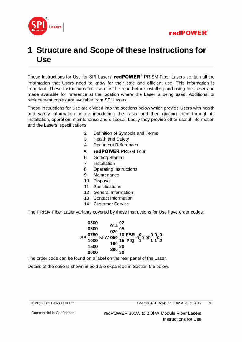
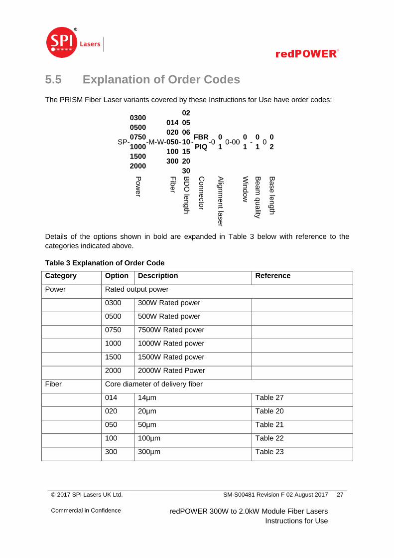
The PRISM Fiber Laser variants covered by these Instructions for Use have order codes:
SP -
0300
0500
0750
1000
1500
2000
- M - W -
014
020
050
100
300
-
02
05
10
15
20
30
- FBR
PIQ - 0
0
1 0 - 00
0
1 - 0
1 0 0
2
The order code can be found on a label on the rear panel of the Laser.
Details of the options shown in bold are expanded in Section 5.5 below.
© 2017 SPI Lasers UK Ltd.
Commercial in Confidence
SM-S00481 Revision F 02 August 2017
redPOWER 300W to 2.0kW Module Fiber Lasers
Instructions for Use
10
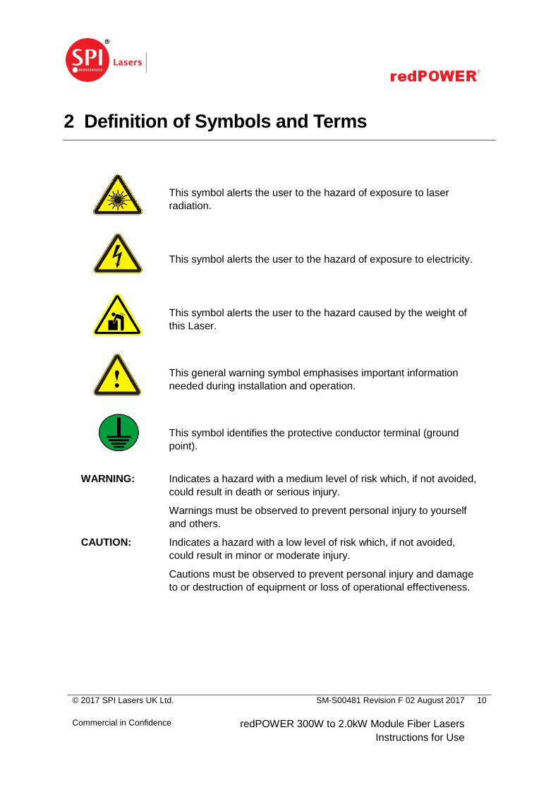
2 Definition of Symbols and Terms
This symbol alerts the user to the hazard of exposure to laser
radiation.
This symbol alerts the user to the hazard of exposure to electricity.
This symbol alerts the user to the hazard caused by the weight of
this Laser.
This general warning symbol emphasises important information
needed during installation and operation.
This symbol identifies the protective conductor terminal (ground
point).
WARNING: Indicates a hazard with a medium level of risk which, if not avoided,
could result in death or serious injury.
Warnings must be observed to prevent personal injury to yourself
and others.
CAUTION: Indicates a hazard with a low level of risk which, if not avoided,
could result in minor or moderate injury.
Cautions must be observed to prevent personal injury and damage
to or destruction of equipment or loss of operational effectiveness.
© 2017 SPI Lasers UK Ltd.
Commercial in Confidence
SM-S00481 Revision F 02 August 2017
redPOWER 300W to 2.0kW Module Fiber Lasers
Instructions for Use
11
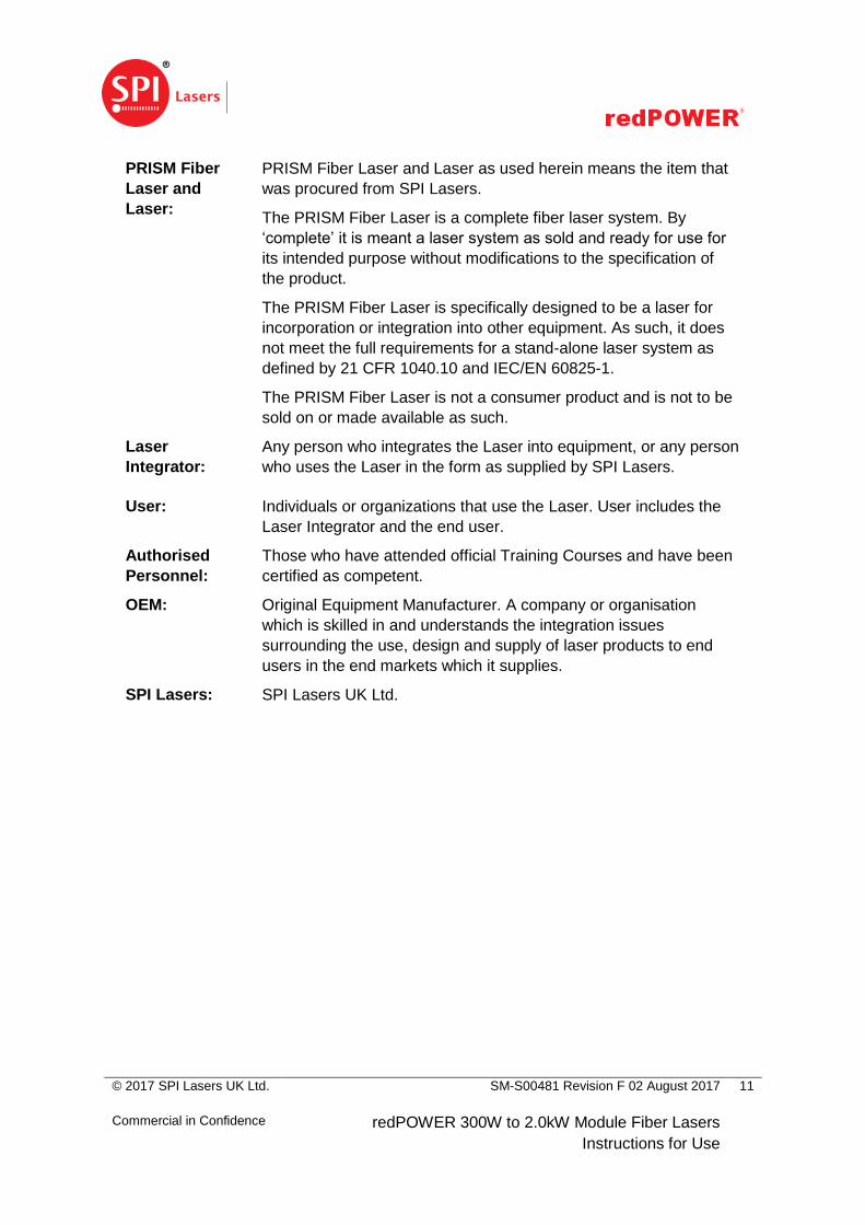
PRISM Fiber
Laser and
Laser:
PRISM Fiber Laser and Laser as used herein means the item that
was procured from SPI Lasers.
The PRISM Fiber Laser is a complete fiber laser system. By
‘complete’ it is meant a laser system as sold and ready for use for
its intended purpose without modifications to the specification of
the product.
The PRISM Fiber Laser is specifically designed to be a laser for
incorporation or integration into other equipment. As such, it does
not meet the full requirements for a stand-alone laser system as
defined by 21 CFR 1040.10 and IEC/EN 60825-1.
The PRISM Fiber Laser is not a consumer product and is not to be
sold on or made available as such.
Laser
Integrator:
Any person who integrates the Laser into equipment, or any person
who uses the Laser in the form as supplied by SPI Lasers.
User: Individuals or organizations that use the Laser. User includes the
Laser Integrator and the end user.
Authorised
Personnel:
Those who have attended official Training Courses and have been
certified as competent.
OEM: Original Equipment Manufacturer. A company or organisation
which is skilled in and understands the integration issues
surrounding the use, design and supply of laser products to end
users in the end markets which it supplies.
SPI Lasers: SPI Lasers UK Ltd.
© 2017 SPI Lasers UK Ltd.
Commercial in Confidence
SM-S00481 Revision F 02 August 2017
redPOWER 300W to 2.0kW Module Fiber Lasers
Instructions for Use
12
3 Health and Safety
3.1 General
This section gives information on the hazards which may be encountered during installation,
operation and maintenance of this PRISM Fiber Laser and steps to reduce the risk. Also
included is information on laser and electrical safety compliance. All safety instructions
including the instructions mentioned in other sections of these Instructions for Use must be
followed. Not following safety instructions may constitute a hazard to Users and third parties or
cause damage to property and the Laser.
Only Authorised Personnel who have been instructed in, and fully understand, the necessary
safety procedures should use this laser. Access to the laser must be restricted to Authorised
Personnel.
Any local safety requirements for the operation of this equipment must be complied with.
Throughout the documentation, ‘WARNING’, and ‘CAUTION’ paragraphs appear. It is the
responsibility and duty of all Users who operate and maintain this equipment to fully
understand the WARNING and CAUTION and act in order to reduce or eliminate hazards.
3.2 Intended Use of the PRISM Fiber Laser
This Laser has been designed exclusively for incorporation or integration into other equipment
for processing:
solid metals, including metal alloys and metal powders
ceramics in both solid and powder form
composite materials
Operating the device within the limits of its designated use requires the user to:
observe the instructions set out in these Instructions for Use
install and use this Laser in compliance with international, national and local
regulations regarding laser safety, for example IEC/EN 60825-1 and 21 CFR 1040.10.
install and use this Laser in compliance with international, national and local
regulations regarding the safety of electrical equipment, for example BS EN 60204
wire and connect the electrical lines to this Laser in compliance with international,
national and local regulations regarding electromagnetic compatibility (EMC), for
example the relevant sections of IEC/EN 61000 and FCC CFR47
not move this Laser when it is switched on (except that the optical connector may be
moved provided that the bending limits of the conduit are observed)
© 2017 SPI Lasers UK Ltd.
Commercial in Confidence
SM-S00481 Revision F 02 August 2017
redPOWER 300W to 2.0kW Module Fiber Lasers
Instructions for Use
13
carry out necessary inspection and maintenance work
This Laser is not intended:
for processing in connection with flammable or explosive materials
for use in an explosion prone environment
SPI Lasers cannot be held liable for any damage resulting from such use. The risk lies entirely
with the User.
3.3 Hazards 3.3.1 Laser Hazards
All Warnings, including those in the Safety Notes and those in other sections of these
Instructions for Use, must be heeded.
Laser emissions from the housing of the Laser and the conduit of the beam delivery optic are
less than the AEL for Class 1 of IEC/EN 60825-1 with a single fault providing that the Fiber
Continuity Monitoring System (FCMS) is correctly implemented by the Laser Integrator.
WARNING: Care must be taken especially when controlling this
PRISM Fiber Laser remotely across a network.
Failure to do so could result in another User being exposed to
hazardous levels of radiation.
It is the responsibility of the Laser Integrator to ensure that when
controlled remotely no hazardous levels of radiation are emitted
when unsafe to do so.
3.3.2 Thermal Hazard
This Laser is designed to be used in a 19” rack cabinet or other housing which prevents
access to surfaces which may get hot during operation.
3.3.3 Materials Processing Hazards
Materials processing can generate vapour, fumes, solid particulates and other air
contaminants that may irritate, be toxic, or even fatal. It is the responsibility of the user to
ensure that all relevant safety precautions are followed and that any legal requirements are
adhered to in accordance with local legislation. It is advised that Material Safety Data Sheets
(MSDS) for any material to be processed are evaluated and that adequate measures for fume
extraction and venting are considered. Interaction of the beam with certain materials can
cause potentially harmful levels of visible radiation to be emitted. Appropriate protective
measures must be taken.

© 2017 SPI Lasers UK Ltd.
Commercial in Confidence
SM-S00481 Revision F 02 August 2017
redPOWER 300W to 2.0kW Module Fiber Lasers
Instructions for Use
14
CAUTION: It is essential that any debris associated with laser
processing is removed and cleaned away on a regular basis.
Failure to do so may result in fire.
3.3.4 Other Hazards
While most of the hazard comes from laser radiation, there are certain non-beam hazards that
are often associated with use of laser systems. The Laser requires an electrical supply and is
water-cooled. Electricity and water, individually or in combination, may create hazards.
It is recommended that the Laser should be installed sufficiently far above the floor to reduce
the risk from electricity in the case of flooding: at least 250mm is recommended.
Mechanical hazards may include moving parts in cutting, welding and material handling
systems.
High temperatures and fire hazards may also result from the operation of Class 4 lasers.
3.4 Compliance
Within the EU, the Laser is CE marked and is supplied with a Declaration of Conformity. The
standards which SPI Lasers declares that the Laser is in conformity with, and the directives
which SPI Lasers declares that the Laser complies with the requirements of are listed in the
Declaration of Conformity.
Within the USA, the Laser is shipped with an appropriately completed FDA 2877 form.
It is the responsibility of the Laser Integrator to ensure that the integrated laser system
conforms with the appropriate standards and complies with the appropriate directives.
Nonetheless, many of the electronic and labelling requirements have been incorporated into
the Laser to facilitate compliance.
3.4.1 Europe: WEEE Directive
Figure 1 WEEE Symbol
This symbol indicates that, at end of life, this Laser should be separately collected from
unsorted waste.
© 2017 SPI Lasers UK Ltd.
Commercial in Confidence
SM-S00481 Revision F 02 August 2017
redPOWER 300W to 2.0kW Module Fiber Lasers
Instructions for Use
15
3.4.2 Europe: RoHS Directive
This Laser is in conformity with European RoHS Directive. Compliance is demonstrated
through conformance with this standard which is harmonised to the RoHS directive:
BS EN 50581:2012
3.4.3 Europe: Machinery Directive
This Laser does not fall within the meaning of ‘machinery’ given in the Machinery Directive,
2006/42/EC, and therefore SPI Lasers cannot declare conformity with the Directive. However
SPI Lasers recognises that Laser Integrators may require the integrated laser system to
comply with the Directive. SPI Lasers has therefore designed for compliance to parts of the
standards listed below which are harmonised to the Machinery Directive:
EN11252:2013
EN13849-1:2015
EN13849-2:2012
EN11554:2008
EN12100:2010
EN12198-1:2000+A1:2008, EN12198-2:2002+A1:2008, EN12198-3:2002+A1:2008
3.4.4 Europe: Low Voltage Directive
This Laser falls outside the scope of the Low Voltage Directive as the Directive applies to
electrical equipment designed for use with a voltage rating of between 75V and 1500V for
direct current. However SPI Lasers recognises that Laser Integrators may require the
integrated laser system to comply with the Directive. SPI Lasers has therefore demonstrated
compliance to parts of the standard given below which is harmonised to the Low Voltage
Directive:
IEC/EN 60825-1
This Laser is specifically designed to be a laser for incorporation or integration into other
equipment. As such, it is not required to, and does not, meet the requirements for a stand-
alone laser system as defined by IEC/EN 60825-1.
During installation it is vital that the laser hazard is fully managed. In particular, the Laser
Integrator is required to provision the engineering requirements detailed in IEC/EN 60825-1.
These include, but are not limited to:
Provision of an additional protective housing which prevents human access or
exposure to laser radiation in excess of the AEL for Class 1 laser systems from the
output aperture. (IEC/EN 60825-1 section 4.2).
© 2017 SPI Lasers UK Ltd.
Commercial in Confidence
SM-S00481 Revision F 02 August 2017
redPOWER 300W to 2.0kW Module Fiber Lasers
Instructions for Use
16
Provision of a remote interlock connector which when open-circuit prevents access to
laser radiation in excess of Class 1M (IEC/EN 60825-1 section 4.4).
Provision of a manual reset to enable resumption of accessible Class 4 laser radiation
emission after interruption of emission caused by use of the remote interlock connector
or an interruption of longer than 5s of electrical mains power (IEC/EN 60825-1 section
4.5).
Provision of a key-operated master control. The key must be removable and the laser
radiation shall not be accessible when the key is removed (IEC/EN 60825-1 section
4.6).
Provision of a fail-safe or redundant audible or visible emission indicator. This must be
repeated at the laser aperture if it is located more than 2m from the original emission
indicator (IEC/EN 60825-1 section 4.7).
Provision of one or more permanently attached means of attenuation (eg beam stop,
attenuator or switch). The beam stop, attenuator or switch shall prevent access to laser
radiation in excess of Class 1M (IEC/EN 60825-1 section 4.8)
Note that the visible alignment laser (if fitted) carries a Class 2 laser rating as defined by
IEC/EN 60825-1.
3.4.5 Europe: EMC Directive
This Laser falls outside the scope of the EMC Directive as it is intended exclusively for an
industrial assembly operation for incorporation into other apparatus. However SPI Lasers
recognises that Laser Integrators may require the integrated laser system to comply with the
directive. SPI Lasers has therefore designed for compliance to parts of the standards listed
below which are harmonised to the EMC Directive:
BS EN 50370-1:2005
BS EN 55011:2009+A1:2010.
3.4.6 USA: CFR Title 21 Part 1040, Food And Drug Administration
This Laser falls outside the scope of 21 CFR part 1040 as 21 CFR part 1040 does not apply to
laser products which are sold to a manufacturer for use as components. However SPI Lasers
recognises that Laser Integrators may require the integrated laser system to comply with the
regulation. SPI Lasers has therefore demonstrated compliance to parts of the European
standard:
IEC/EN 60825-1
Under Laser Notice 50, CDRH will not object to conformance with many sections of IEC
60825-1, as amended, as alternatives to comparable sections of 21 CFR §1040.10.
© 2017 SPI Lasers UK Ltd.
Commercial in Confidence
SM-S00481 Revision F 02 August 2017
redPOWER 300W to 2.0kW Module Fiber Lasers
Instructions for Use
17
3.4.7 USA: CFR Title 47, Federal Communications Commission
This Laser is designed for compliance with:
FCC CFR47: §15.109 Radiated emission limits.
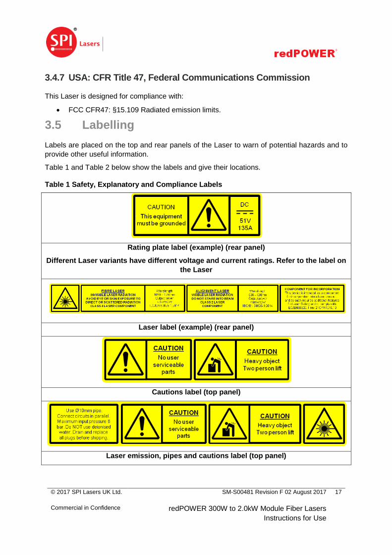
3.5 Labelling
Labels are placed on the top and rear panels of the Laser to warn of potential hazards and to
provide other useful information.
Table 1 and Table 2 below show the labels and give their locations.
Table 1 Safety, Explanatory and Compliance Labels
Rating plate label (example) (rear panel)
Different Laser variants have different voltage and current ratings. Refer to the label on
the Laser
Laser label (example) (rear panel)
Cautions label (top panel)
Laser emission, pipes and cautions label (top panel)
© 2017 SPI Lasers UK Ltd.
Commercial in Confidence
SM-S00481 Revision F 02 August 2017
redPOWER 300W to 2.0kW Module Fiber Lasers
Instructions for Use
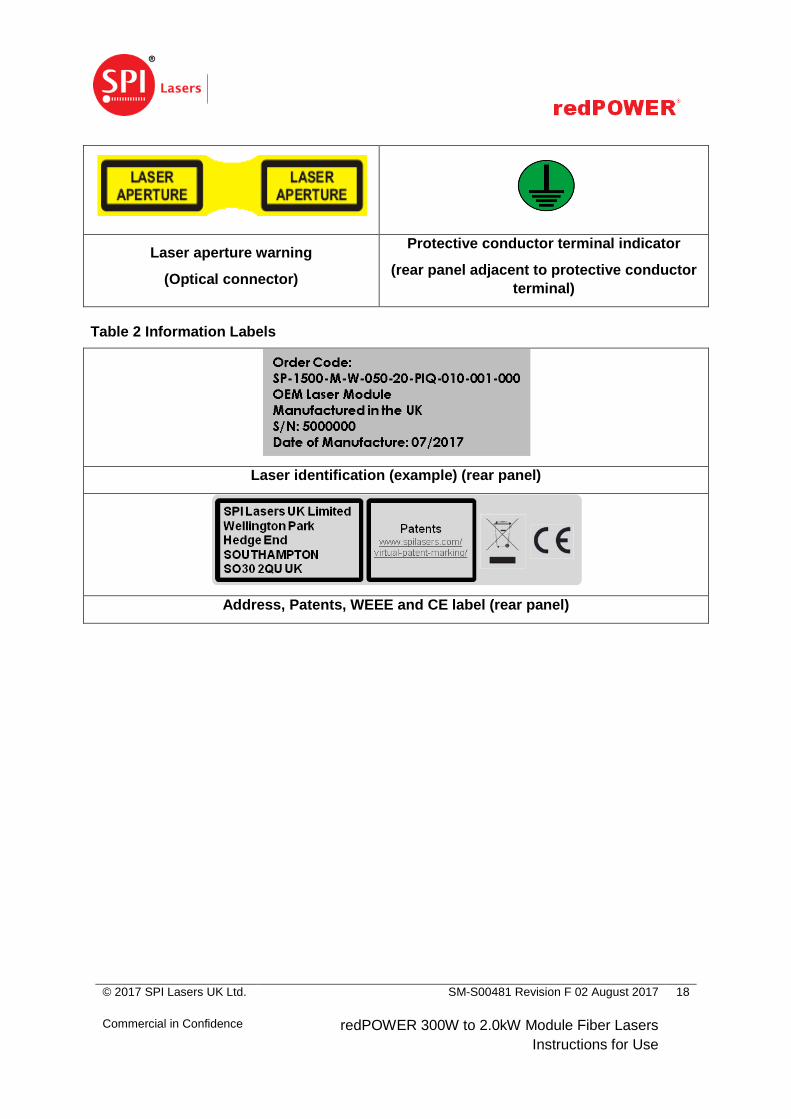
18
Laser aperture warning
(Optical connector)
Protective conductor terminal indicator
(rear panel adjacent to protective conductor
terminal)
Table 2 Information Labels
Laser identification (example) (rear panel)
Address, Patents, WEEE and CE label (rear panel)
© 2017 SPI Lasers UK Ltd.
Commercial in Confidence
SM-S00481 Revision F 02 August 2017
redPOWER 300W to 2.0kW Module Fiber Lasers
Instructions for Use
19
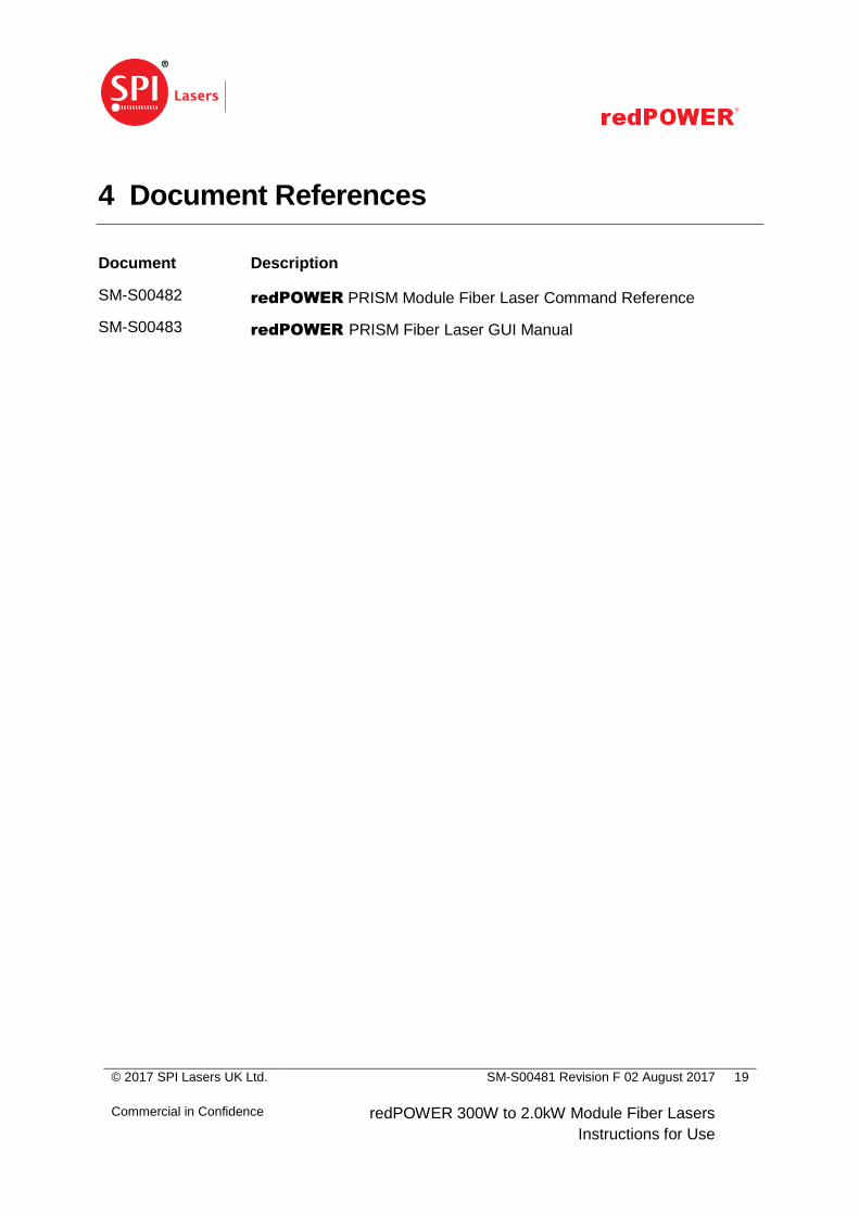
4 Document References
Document
number
Description
SM-S00482 redPOWER PRISM Module Fiber Laser Command Reference
SM-S00483 redPOWER PRISM Fiber Laser GUI Manual
© 2017 SPI Lasers UK Ltd.
Commercial in Confidence
SM-S00481 Revision F 02 August 2017
redPOWER 300W to 2.0kW Module Fiber Lasers
Instructions for Use
20
5 redPOWER PRISM Tour
The range of redPOWER PRISM Fiber Lasers builds on many years of experience of SPI
Lasers in designing, developing and supplying fiber lasers into a wide range of industrial laser
processing applications. It gives laser integrators the capability to manufacture industrial laser
machines with maximum output power levels from 300W to 1.5kW. They can be operated in
continuous wave (CW) or modulated (CWM) modes for applications enabled by fiber lasers
and applications traditionally serviced by lamp pumped and diode pumped solid-state lasers.
A flexible control architecture has been implemented using a combination of analogue, serial
and logic user interfaces.
The optical power is generated by SPI Lasers’ proprietary1 GTWave® active fiber technology
and reliable pump diodes to produce a high power, high brightness output. The output is
guided to the Laser Integrator’s optics by single mode (SM) or multimode (MM) delivery fibers.
The delivery fiber is usually supplied with a PIPA-Q optical connector, which is compatible with
industry standards, and a ruggedized conduit including SPI Lasers’ Fiber Continuity
Monitoring System (FCMS) to protect it.
To give Laser Integrators a flexible approach to multi-kW fiber lasers, PRISM Fiber Lasers
may be supplied without an optical connector to allow a spliced connection to a High Power
Combiner (HPC) supplied by SPI Lasers.
1 US 6,826,335, US 7,221,822, US 7,660,034, US 8,270,070, US 8,743,454 and granted patents in other territories
© 2017 SPI Lasers UK Ltd.
Commercial in Confidence
SM-S00481 Revision F 02 August 2017
redPOWER 300W to 2.0kW Module Fiber Lasers
Instructions for Use
21
5.1 Key Parts
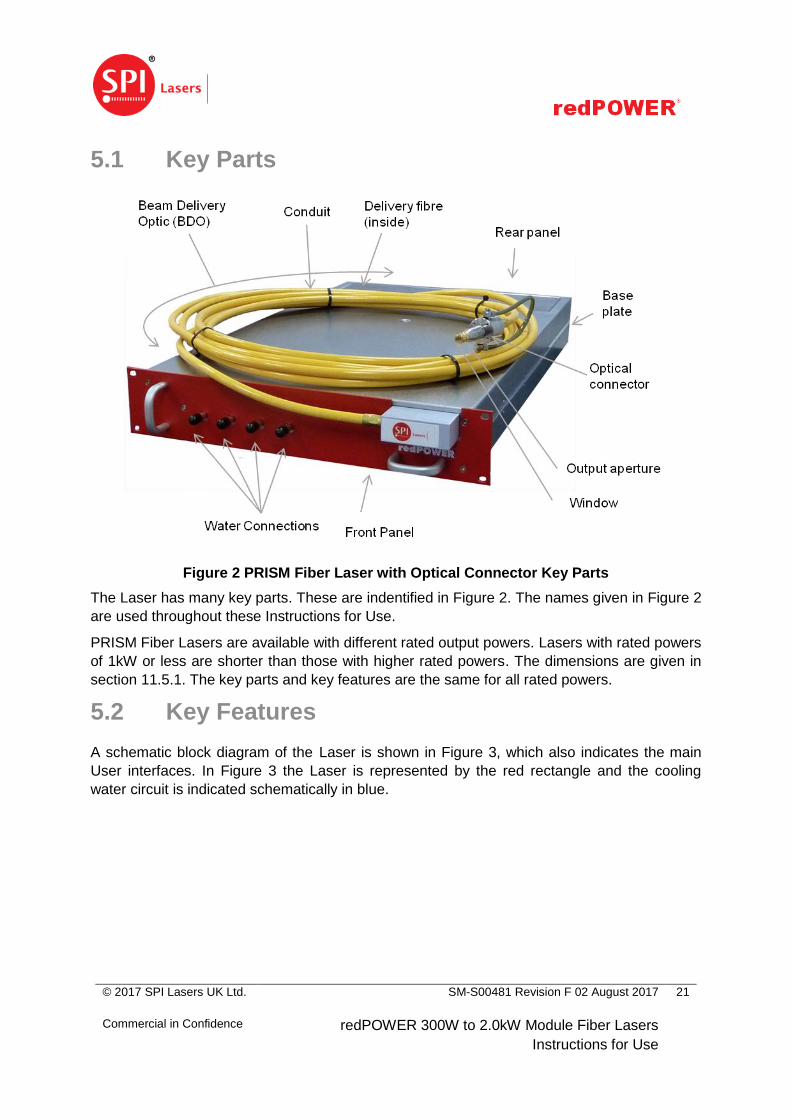
Figure 2 PRISM Fiber Laser with Optical Connector Key Parts
The Laser has many key parts. These are indentified in Figure 2. The names given in Figure 2
are used throughout these Instructions for Use.
PRISM Fiber Lasers are available with different rated output powers. Lasers with rated powers
of 1kW or less are shorter than those with higher rated powers. The dimensions are given in
section 11.5.1. The key parts and key features are the same for all rated powers.
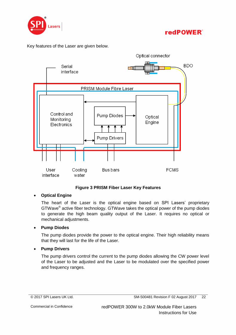
5.2 Key Features
A schematic block diagram of the Laser is shown in Figure 3, which also indicates the main
User interfaces. In Figure 3 the Laser is represented by the red rectangle and the cooling
water circuit is indicated schematically in blue.
© 2017 SPI Lasers UK Ltd.
Commercial in Confidence
SM-S00481 Revision F 02 August 2017
redPOWER 300W to 2.0kW Module Fiber Lasers
Instructions for Use
22
Key features of the Laser are given below.
Figure 3 PRISM Fiber Laser Key Features
Optical Engine
The heart of the Laser is the optical engine based on SPI Lasers’ proprietary
GTWave® active fiber technology. GTWave takes the optical power of the pump diodes
to generate the high beam quality output of the Laser. It requires no optical or
mechanical adjustments.
Pump Diodes
The pump diodes provide the power to the optical engine. Their high reliability means
that they will last for the life of the Laser.
Pump Drivers
The pump drivers control the current to the pump diodes allowing the CW power level
of the Laser to be adjusted and the Laser to be modulated over the specified power
and frequency ranges.

© 2017 SPI Lasers UK Ltd.
Commercial in Confidence
SM-S00481 Revision F 02 August 2017
redPOWER 300W to 2.0kW Module Fiber Lasers
Instructions for Use
23
Beam Delivery
The delivery fiber guides the laser power from the optical engine into the Laser
Integrator’s optics. Options are available for the delivery fiber type and output
connector. Types include single mode and multimode, with different multimode core
diameters available. The delivery fiber is usually supplied with an industry standard
PIPA-Q optical connector. In this case a ruggedized conduit including SPI Lasers’
Fiber Continuity Monitoring System (FCMS) protects the delivery fiber. The optical
connector and ruggedized conduit with FCMS are referred to as the beam delivery
optic (BDO). When supplied without an optical connector mechanical protection is
provided by polymer jacket and Kevlar® reinforcement within a conduit, but there is no
FCMS.
Fiber Continuity Monitoring System (FCMS)
The FCMS is a thin copper wire wound around the delivery fiber. Should the delivery
fiber fail, the escaping laser power fuses the FCMS wire. The Laser Integrator must
monitor the continuity of the FCMS as described in Section 7.6.5 and shut the Laser
down to prevent the beam burning through the conduit and so prevent exposure of
Users to laser radiation.
Back Reflection Monitoring and Protection
In some laser processes the laser power couples poorly into the work piece causing
some of the power to be reflected back into the optical connector and coupled into the
delivery fiber. This back reflection is most likely to occur
o when setting focus at high power
o when processing highly reflective materials such as brass, copper and
aluminium, especially at normal incidence
o when operating away from the focal point of the process head
o during the piercing phase of laser cutting
This back reflected power has the potential to cause damage to the optical connector
and delivery fiber due to overheating. It may also to produce power instabilities due to
interaction with the optical engine.
The Laser is protected against back reflected power with active and passive measures.
Thus there is no need to employ additional optical components (such as optical
isolators), as is common with other fiber lasers, bringing cost and processing
disadvantages. The protection offered by the Laser comes from the design of the
optical connector and optical engine, and the use of sensors to monitor the back-
reflected power. In extreme cases, the Laser shuts itself down before damage occurs.
© 2017 SPI Lasers UK Ltd.
Commercial in Confidence
SM-S00481 Revision F 02 August 2017
redPOWER 300W to 2.0kW Module Fiber Lasers
Instructions for Use
24
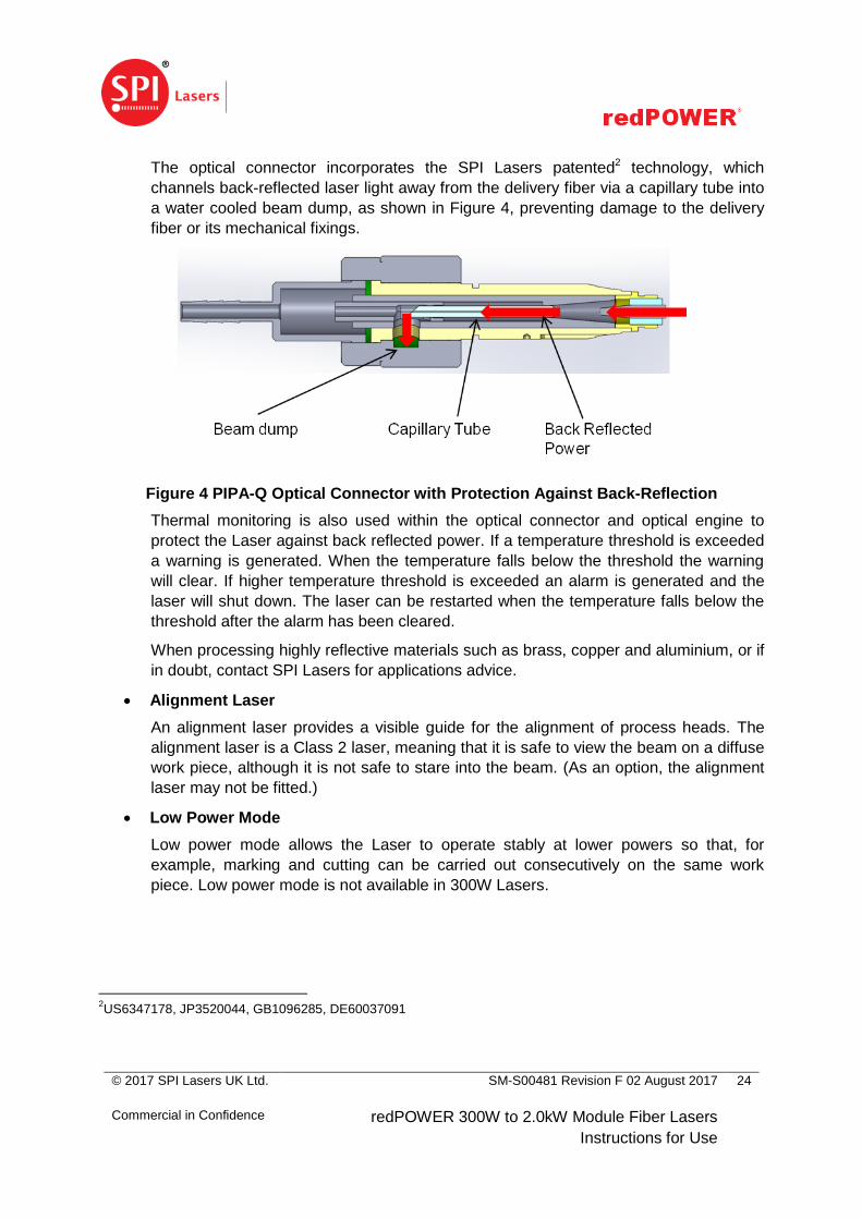
The optical connector incorporates the SPI Lasers patented2 technology, which
channels back-reflected laser light away from the delivery fiber via a capillary tube into
a water cooled beam dump, as shown in Figure 4, preventing damage to the delivery
fiber or its mechanical fixings.
Figure 4 PIPA-Q Optical Connector with Protection Against Back-Reflection
Thermal monitoring is also used within the optical connector and optical engine to
protect the Laser against back reflected power. If a temperature threshold is exceeded
a warning is generated. When the temperature falls below the threshold the warning
will clear. If higher temperature threshold is exceeded an alarm is generated and the
laser will shut down. The laser can be restarted when the temperature falls below the
threshold after the alarm has been cleared.
When processing highly reflective materials such as brass, copper and aluminium, or if
in doubt, contact SPI Lasers for applications advice.
Alignment Laser
An alignment laser provides a visible guide for the alignment of process heads. The
alignment laser is a Class 2 laser, meaning that it is safe to view the beam on a diffuse
work piece, although it is not safe to stare into the beam. (As an option, the alignment
laser may not be fitted.)
Low Power Mode
Low power mode allows the Laser to operate stably at lower powers so that, for
example, marking and cutting can be carried out consecutively on the same work
piece. Low power mode is not available in 300W Lasers.
2US6347178, JP3520044, GB1096285, DE60037091

© 2017 SPI Lasers UK Ltd.
Commercial in Confidence
SM-S00481 Revision F 02 August 2017
redPOWER 300W to 2.0kW Module Fiber Lasers
Instructions for Use
25
Control and Monitoring Electronics
The control and monitoring electronics provide basic control and monitoring of the
Laser. Logic and analogue interfaces give Laser Integrators basic set point control and
status monitoring.
o Logic controls include Enable and Modulate, and monitors include Ready and
Emitting as well as alarms and warnings.
o Analogue controls include Power Set, and monitors include Output Power
Monitor and Back Reflected Power Monitor.
The Output Power Monitor may be used to improve power stability during changes in
ambient conditions as it allows Laser Integrators to provide closed loop control.
However the monitor may not accurately represent the output power when the output
is modulated or when processing highly reflective materials. Under such conditions,
SPI Lasers does not recommend using closed loop control.
To facilitate integration of multiple Lasers, all control and monitoring functions are
available using RS-232 and RS-485 serial interfaces. CAN bus is also available using
SPI Lasers’ proprietary protocol.
Mounting
The Laser can be fitted into a standard 19” rack cabinet. The front panel has the
conventional 2U dimensions.
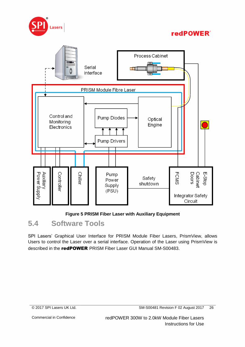
5.3 Auxiliary Equipment
Installation of the Laser within an integrated laser system requires the provision of auxiliary
equipment for power and control as shown in Figure 5. A low noise DC power supply is
required to power the pump diodes. A temperature controlled supply of water is required for
cooling. A low noise 24V DC power supply is required for the monitoring circuits.
Requirements for the auxiliary equipment are given in the sections indicated below.
Pump power supply – Section 11.3.1
Auxiliary power supply – Section 11.3.1
Chiller – Section 11.3.2
It is the responsibility of the Laser Integrator to provide an integrator safety circuit which can
enable the Laser when the process cabinet doors are shut and disable it to make the process
cabinet safe both as required in normal operation and after activation of the emergency stop.
The Laser has no internal safety circuits.
SPI Lasers does not assume responsibility for specific integration decisions affecting the
safety and compliance to international standards of the Laser Integrator’s final laser product or
system.
© 2017 SPI Lasers UK Ltd.
Commercial in Confidence
SM-S00481 Revision F 02 August 2017
redPOWER 300W to 2.0kW Module Fiber Lasers
Instructions for Use
26
Figure 5 PRISM Fiber Laser with Auxiliary Equipment
5.4 Software Tools
SPI Lasers’ Graphical User Interface for PRISM Module Fiber Lasers, PrismView, allows
Users to control the Laser over a serial interface. Operation of the Laser using PrismView is
described in the redPOWER PRISM Fiber Laser GUI Manual SM-S00483.
© 2017 SPI Lasers UK Ltd.
Commercial in Confidence
SM-S00481 Revision F 02 August 2017
redPOWER 300W to 2.0kW Module Fiber Lasers
Instructions for Use
27
5.5 Explanation of Order Codes
The PRISM Fiber Laser variants covered by these Instructions for Use have order codes:
SP -
0300
0500
0750
1000
1500
2000
- M - W -
014
020
050
100
300
-
02
05
06
10
15
20
30
- FBR
PIQ - 0
0
1 0 - 00
0
1 -
0
1 0
0
2
Pow
er
Fib
er
BD
O le
ng
th
Co
nn
ecto
r
Alig
nm
ent la
ser
Win
dow
Be
am
qua
lity
Ba
se le
ng
th
Details of the options shown in bold are expanded in Table 3 below with reference to the
categories indicated above.
Table 3 Explanation of Order Code
Category Option Description Reference
Power Rated output power
0300 300W Rated power
0500 500W Rated power
0750 7500W Rated power
1000 1000W Rated power
1500 1500W Rated power
2000 2000W Rated Power
Fiber Core diameter of delivery fiber
014 14µm Table 27
020 20µm Table 20
050 50µm Table 21
100 100µm Table 22
300 300µm Table 23
© 2017 SPI Lasers UK Ltd.
Commercial in Confidence
SM-S00481 Revision F 02 August 2017
redPOWER 300W to 2.0kW Module Fiber Lasers
Instructions for Use
28
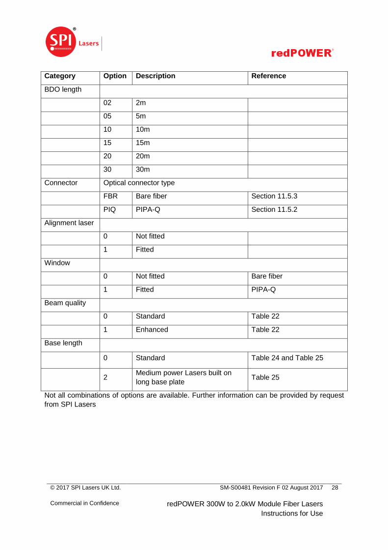
Category Option Description Reference
BDO length
02 2m
05 5m
10 10m
15 15m
20 20m
30 30m
Connector Optical connector type
FBR Bare fiber Section 11.5.3
PIQ PIPA-Q Section 11.5.2
Alignment laser
0 Not fitted
1 Fitted
Window
0 Not fitted Bare fiber
1 Fitted PIPA-Q
Beam quality
0 Standard Table 22
1 Enhanced Table 22
Base length
0 Standard Table 24 and Table 25
2
Medium power Lasers built on
long base plate Table 25
Not all combinations of options are available. Further information can be provided by request
from SPI Lasers
© 2017 SPI Lasers UK Ltd.
Commercial in Confidence
SM-S00481 Revision F 02 August 2017
redPOWER 300W to 2.0kW Module Fiber Lasers
Instructions for Use
29
6 Getting Started
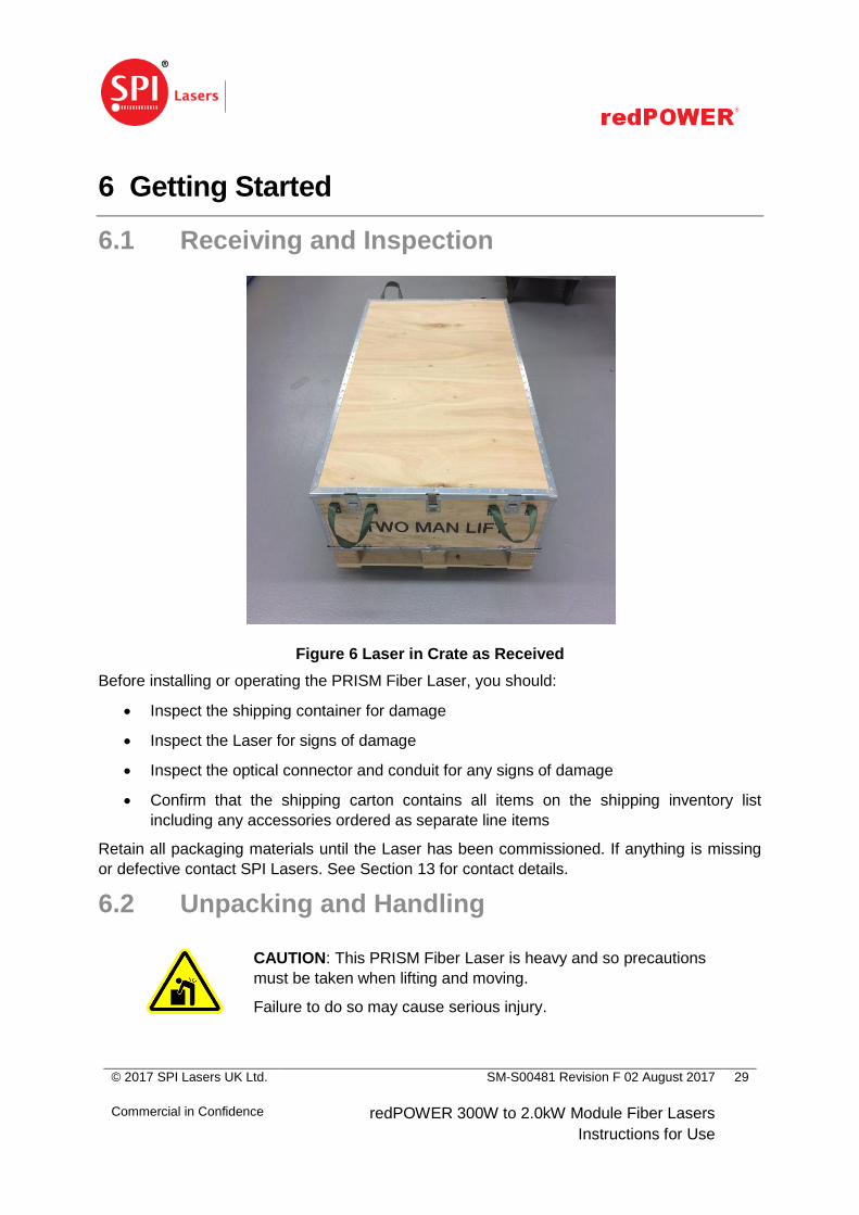
6.1 Receiving and Inspection
Figure 6 Laser in Crate as Received
Before installing or operating the PRISM Fiber Laser, you should:
Inspect the shipping container for damage
Inspect the Laser for signs of damage
Inspect the optical connector and conduit for any signs of damage
Confirm that the shipping carton contains all items on the shipping inventory list
including any accessories ordered as separate line items
Retain all packaging materials until the Laser has been commissioned. If anything is missing
or defective contact SPI Lasers. See Section 13 for contact details.
6.2 Unpacking and Handling
CAUTION: This PRISM Fiber Laser is heavy and so precautions
must be taken when lifting and moving.
Failure to do so may cause serious injury.
© 2017 SPI Lasers UK Ltd.
Commercial in Confidence
SM-S00481 Revision F 02 August 2017
redPOWER 300W to 2.0kW Module Fiber Lasers
Instructions for Use
30
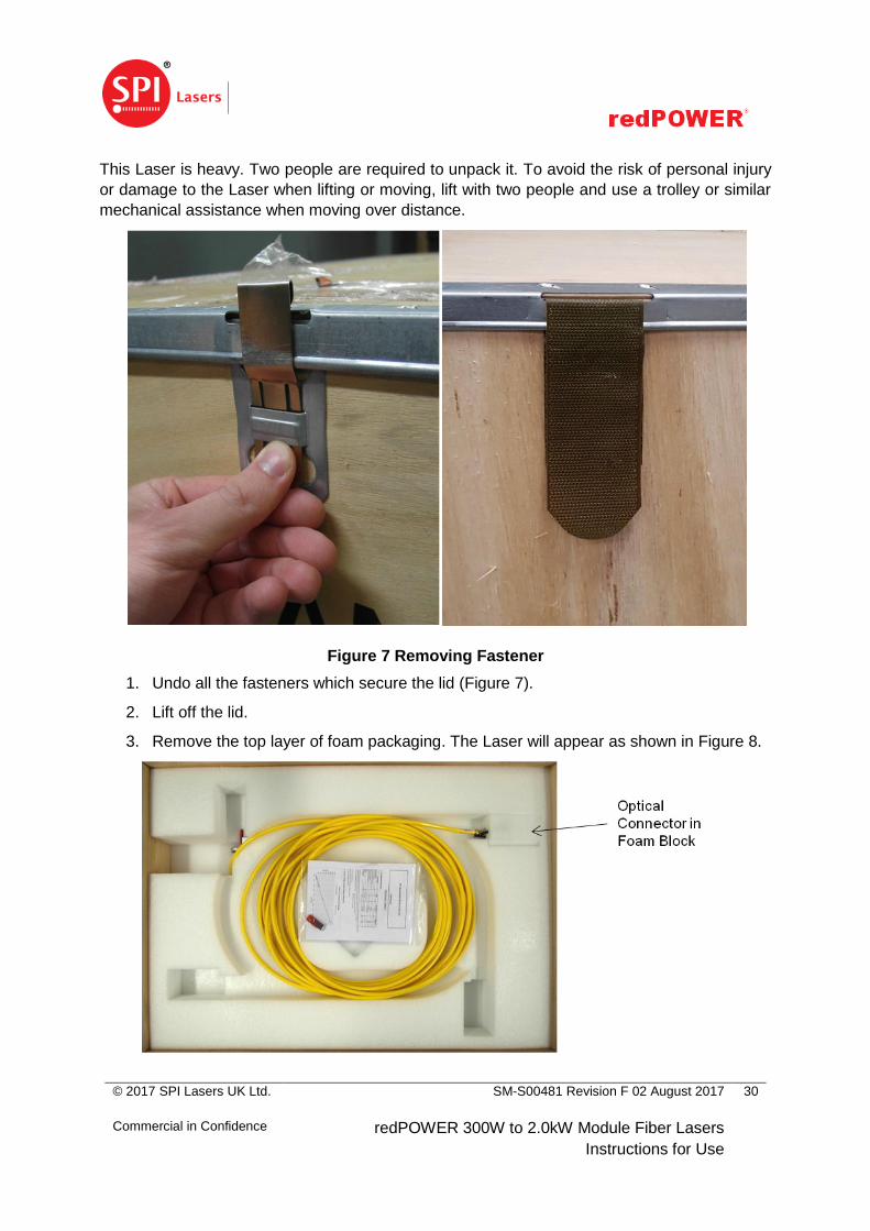
This Laser is heavy. Two people are required to unpack it. To avoid the risk of personal injury
or damage to the Laser when lifting or moving, lift with two people and use a trolley or similar
mechanical assistance when moving over distance.
Figure 7 Removing Fastener
1. Undo all the fasteners which secure the lid (Figure 7).
2. Lift off the lid.
3. Remove the top layer of foam packaging. The Laser will appear as shown in Figure 8.
© 2017 SPI Lasers UK Ltd.
Commercial in Confidence
SM-S00481 Revision F 02 August 2017
redPOWER 300W to 2.0kW Module Fiber Lasers
Instructions for Use
31
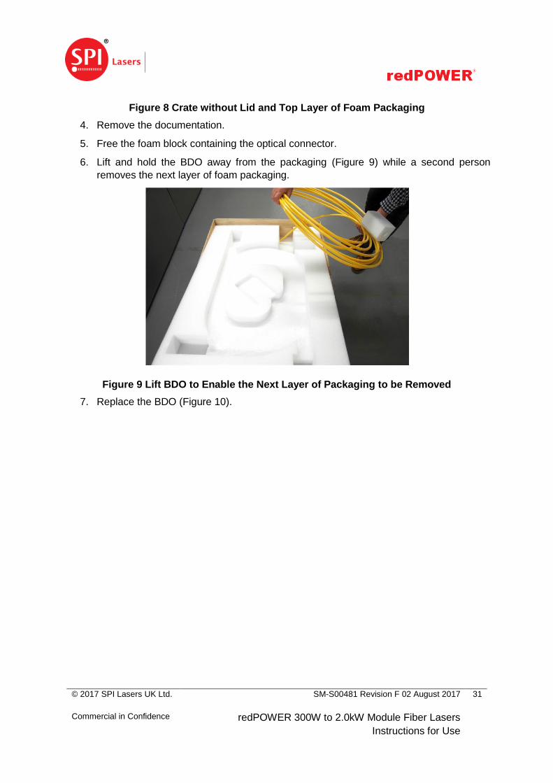
Figure 8 Crate without Lid and Top Layer of Foam Packaging
4. Remove the documentation.
5. Free the foam block containing the optical connector.
6. Lift and hold the BDO away from the packaging (Figure 9) while a second person
removes the next layer of foam packaging.
Figure 9 Lift BDO to Enable the Next Layer of Packaging to be Removed
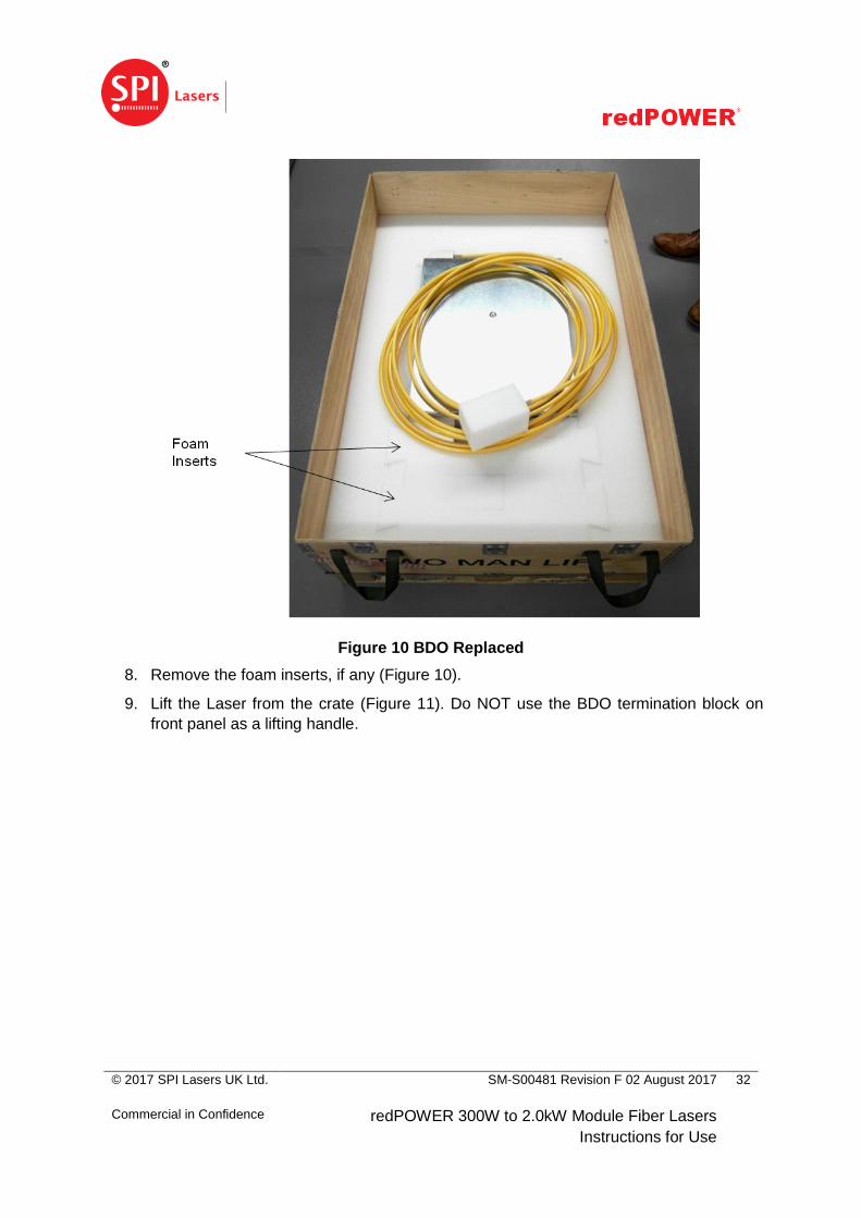
7. Replace the BDO (Figure 10).
© 2017 SPI Lasers UK Ltd.
Commercial in Confidence
SM-S00481 Revision F 02 August 2017
redPOWER 300W to 2.0kW Module Fiber Lasers
Instructions for Use
32
Figure 10 BDO Replaced
8. Remove the foam inserts, if any (Figure 10).
9. Lift the Laser from the crate (Figure 11). Do NOT use the BDO termination block on
front panel as a lifting handle.
© 2017 SPI Lasers UK Ltd.
Commercial in Confidence
SM-S00481 Revision F 02 August 2017
redPOWER 300W to 2.0kW Module Fiber Lasers
Instructions for Use
33
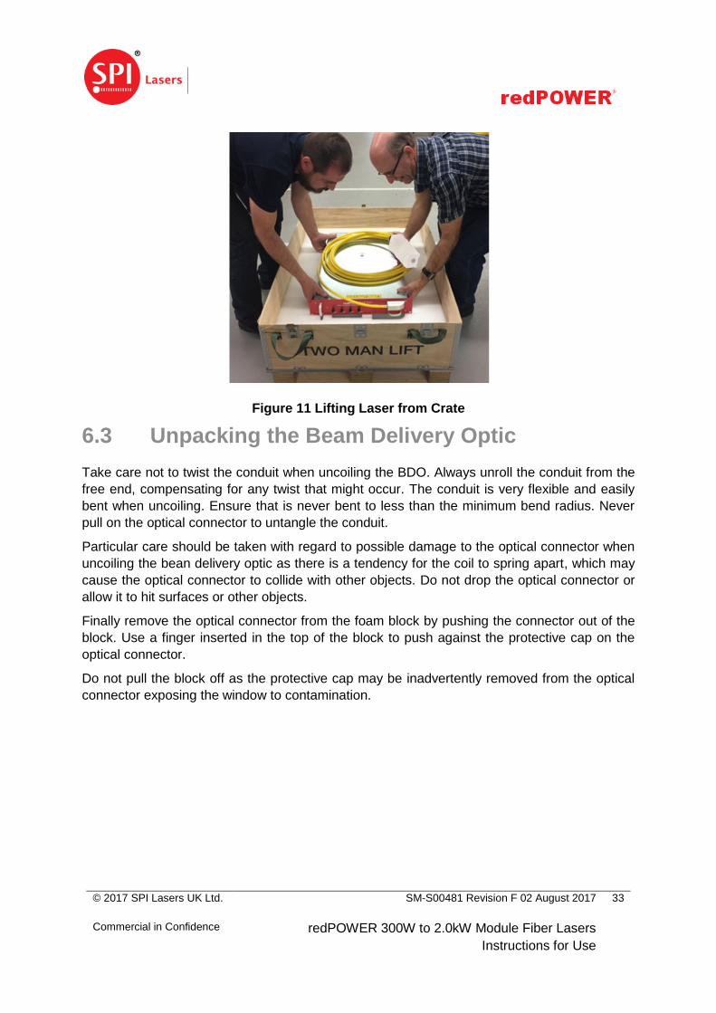
Figure 11 Lifting Laser from Crate
6.3 Unpacking the Beam Delivery Optic
Take care not to twist the conduit when uncoiling the BDO. Always unroll the conduit from the
free end, compensating for any twist that might occur. The conduit is very flexible and easily
bent when uncoiling. Ensure that is never bent to less than the minimum bend radius. Never
pull on the optical connector to untangle the conduit.
Particular care should be taken with regard to possible damage to the optical connector when
uncoiling the bean delivery optic as there is a tendency for the coil to spring apart, which may
cause the optical connector to collide with other objects. Do not drop the optical connector or
allow it to hit surfaces or other objects.
Finally remove the optical connector from the foam block by pushing the connector out of the
block. Use a finger inserted in the top of the block to push against the protective cap on the
optical connector.
Do not pull the block off as the protective cap may be inadvertently removed from the optical
connector exposing the window to contamination.
© 2017 SPI Lasers UK Ltd.
Commercial in Confidence
SM-S00481 Revision F 02 August 2017
redPOWER 300W to 2.0kW Module Fiber Lasers
Instructions for Use
34
7 Installation
7.1 Safety and Compliance During Installation
CAUTION: This PRISM Fiber Laser is heavy and so precautions
must be taken when lifting and moving.
Failure to do so may cause serious injury.
The Laser is heavy. To avoid the risk of personal injury or damage to the Laser when lifting or
moving, lift with two people and use a trolley or similar mechanical assistance when moving
over distance.
Before installation reference must be made to Section 3 regarding laser safety, electrical
safety, EMC and compliance. When installed, the laser and the additional equipment required
to operate it must not obstruct access to safety devices or impair their operation.
It is recommended that installation is done in the sequence of the following sections, with
water connections made and checked before electrical connections are made.
7.2 Location and Environment
This Laser is designed to be used in a 19” rack cabinet or other housing.
This Laser is designed for operation within the environment specified in Table 10. Operating
the Laser beyond the limits of the environmental specification may lead to accelerated
component ageing and performance degradation. As the Laser is water-cooled care must be
taken to ensure that it is always operated above the dew point so that internal condensation is
avoided. Refer to Figure 33 for a chart showing the relationship between relative humidity,
ambient air temperature and cooling water temperature for non-condensing operation.
This Laser must not be installed in a corrosive atmosphere.
This Laser must not be exposed to high levels of optical radiation, for instance laser radiation
from materials processing.
This Laser is sealed against dust and water ingress to IP52 to BS EN 60529:1992+A2:2013
with the exception of the electrical connectors which are rated IP50. The laser integrator must
ensure that when installed the Laser is not likely to be exposed to water, for instance from
coolant leaks.
At least 100mm clear space must be provided around the Laser to allow the BDO to be routed
correctly.
© 2017 SPI Lasers UK Ltd.
Commercial in Confidence
SM-S00481 Revision F 02 August 2017
redPOWER 300W to 2.0kW Module Fiber Lasers
Instructions for Use
35
The optical connector shall be mounted in a protective housing which prevents human access
to laser radiation (including errant radiation) in excess of the AEL for class 1, for example a
housing meeting the requirements of EN 60825-4. The protective housing shall withstand
exposures under reasonably foreseeable single fault conditions without human intervention.
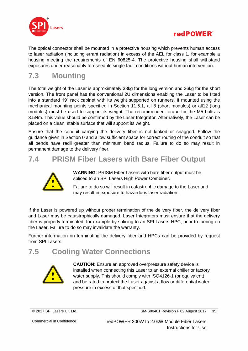
7.3 Mounting
The total weight of the Laser is approximately 38kg for the long version and 26kg for the short
version. The front panel has the conventional 2U dimensions enabling the Laser to be fitted
into a standard 19” rack cabinet with its weight supported on runners. If mounted using the
mechanical mounting points specified in Section 11.5.1, all 8 (short modules) or all12 (long
modules) must be used to support its weight. The recommended torque for the M5 bolts is
3.5Nm. This value should be confirmed by the Laser Integrator. Alternatively, the Laser can be
placed on a clean, stable surface that will support its weight.
Ensure that the conduit carrying the delivery fiber is not kinked or snagged. Follow the
guidance given in Section 0 and allow sufficient space for correct routing of the conduit so that
all bends have radii greater than minimum bend radius. Failure to do so may result in
permanent damage to the delivery fiber.
7.4 PRISM Fiber Lasers with Bare Fiber Output
WARNING: PRISM Fiber Lasers with bare fiber output must be
spliced to an SPI Lasers High Power Combiner.
Failure to do so will result in catastrophic damage to the Laser and
may result in exposure to hazardous laser radiation.
If the Laser is powered up without proper termination of the delivery fiber, the delivery fiber
and Laser may be catastrophically damaged. Laser Integrators must ensure that the delivery
fiber is properly terminated, for example by splicing to an SPI Lasers HPC, prior to turning on
the Laser. Failure to do so may invalidate the warranty.
Further information on terminating the delivery fiber and HPCs can be provided by request
from SPI Lasers.
7.5 Cooling Water Connections
CAUTION: Ensure an approved overpressure safety device is
installed when connecting this Laser to an external chiller or factory
water supply. This should comply with ISO4126-1 (or equivalent)
and be rated to protect the Laser against a flow or differential water
pressure in excess of that specified.
© 2017 SPI Lasers UK Ltd.
Commercial in Confidence
SM-S00481 Revision F 02 August 2017
redPOWER 300W to 2.0kW Module Fiber Lasers
Instructions for Use
36
CAUTION: If coolant is allowed to enter this Laser enclosure, do
not use the Laser and contact SPI Lasers immediately.
Failure to do so may result in electrical shock and damage to the
Laser.
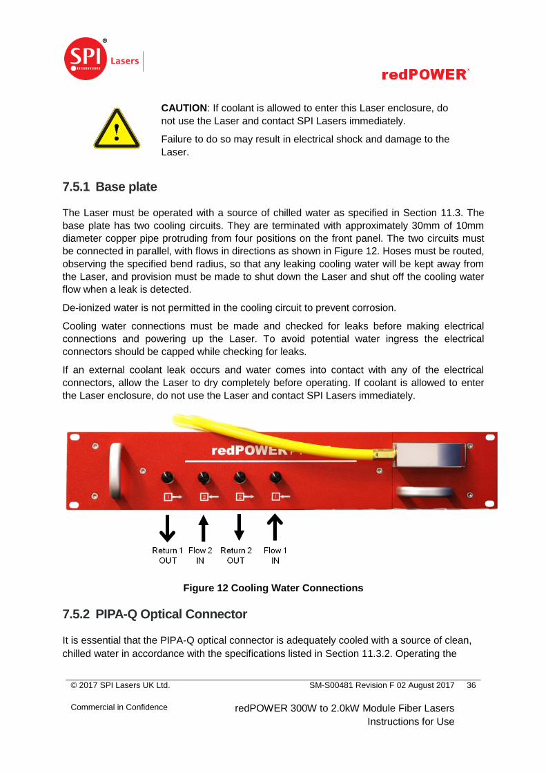
7.5.1 Base plate
The Laser must be operated with a source of chilled water as specified in Section 11.3. The
base plate has two cooling circuits. They are terminated with approximately 30mm of 10mm
diameter copper pipe protruding from four positions on the front panel. The two circuits must
be connected in parallel, with flows in directions as shown in Figure 12. Hoses must be routed,
observing the specified bend radius, so that any leaking cooling water will be kept away from
the Laser, and provision must be made to shut down the Laser and shut off the cooling water
flow when a leak is detected.
De-ionized water is not permitted in the cooling circuit to prevent corrosion.
Cooling water connections must be made and checked for leaks before making electrical
connections and powering up the Laser. To avoid potential water ingress the electrical
connectors should be capped while checking for leaks.
If an external coolant leak occurs and water comes into contact with any of the electrical
connectors, allow the Laser to dry completely before operating. If coolant is allowed to enter
the Laser enclosure, do not use the Laser and contact SPI Lasers immediately.
Figure 12 Cooling Water Connections
7.5.2 PIPA-Q Optical Connector
It is essential that the PIPA-Q optical connector is adequately cooled with a source of clean,
chilled water in accordance with the specifications listed in Section 11.3.2. Operating the

© 2017 SPI Lasers UK Ltd.
Commercial in Confidence
SM-S00481 Revision F 02 August 2017
redPOWER 300W to 2.0kW Module Fiber Lasers
Instructions for Use
37
PIPA-Q optical connector without an adequate flow of cooling water may result in catastrophic
damage.
The inlet and outlet water connections are SMC MS-5HLH-6 type miniature hose elbows
suitable for 6mm LLDPE or polyurethane tubing.
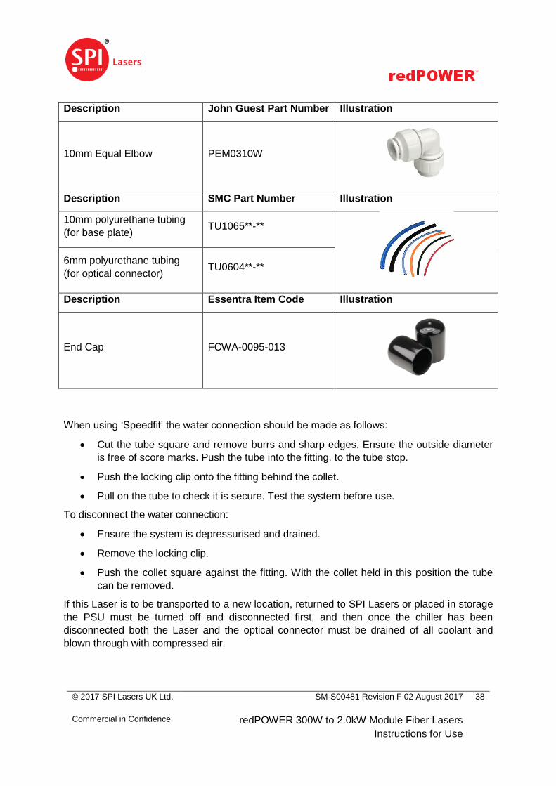
7.5.3 Cooling Water Fittings
The Laser is not supplied with water fittings. SPI Lasers recommends that the widely available
push-on John Guest ‘Speedfit’ water connections are used to connect the cooling circuit to the
chilled water supply. Ensure that the pipes are clean before adding the connections and that
the correct locking clips are used. John Guest part numbers are given in Table 4.
Table 4 Water Tubing and Fittings
Description John Guest Part Number Illustration
10mm Equal Elbow PM0310E
10mm Equal Straight
Connector PM0410E
10mm Locking Clip PM1810R
10mm Plug PM0810R
10mm LLDPE Tubing (for
base plate) PE-1007-100M-*
6mm LLDPE Tubing (for
optical connector) PE-0604-0100M-*
© 2017 SPI Lasers UK Ltd.
Commercial in Confidence
SM-S00481 Revision F 02 August 2017
redPOWER 300W to 2.0kW Module Fiber Lasers
Instructions for Use
38
Description John Guest Part Number Illustration
10mm Equal Elbow PEM0310W
Description SMC Part Number Illustration
10mm polyurethane tubing
(for base plate) TU1065**-**
6mm polyurethane tubing
(for optical connector) TU0604**-**
Description Essentra Item Code Illustration
End Cap FCWA-0095-013
When using ‘Speedfit’ the water connection should be made as follows:
Cut the tube square and remove burrs and sharp edges. Ensure the outside diameter
is free of score marks. Push the tube into the fitting, to the tube stop.
Push the locking clip onto the fitting behind the collet.
Pull on the tube to check it is secure. Test the system before use.
To disconnect the water connection:
Ensure the system is depressurised and drained.
Remove the locking clip.
Push the collet square against the fitting. With the collet held in this position the tube
can be removed.
If this Laser is to be transported to a new location, returned to SPI Lasers or placed in storage
the PSU must be turned off and disconnected first, and then once the chiller has been
disconnected both the Laser and the optical connector must be drained of all coolant and
blown through with compressed air.

© 2017 SPI Lasers UK Ltd.
Commercial in Confidence
SM-S00481 Revision F 02 August 2017
redPOWER 300W to 2.0kW Module Fiber Lasers
Instructions for Use
39
7.6 Electrical Connections
CAUTION: This PRISM Fiber Laser must be grounded for safety
and to comply with regional electrical codes.
Failure to do so may result in electric shock and incorrect operation
of the Laser.
For safe operation of this Laser the electrical connections given in the following sections need
to be made. All electrical connections should use cables of the shortest practical length.
Before making electrical connections and powering up the Laser, the cooling water
connections must be made and checked for leaks with the electrical connectors protected
from water splashes. For safety, the Laser must be connected to an external protective
earthing system before any other electrical connections are made. The Laser is not ‘hot
pluggable’: all electrical connectors must be mated and secured in place before power is
applied.
All figures in this section indicate the pin positions when looking at the connector on the rear
panel of the Laser.
To operate this Laser two power connections and a control connection, which can be serial
(RS-232, RS-485 or CAN bus) or analogue and logic, must be made.
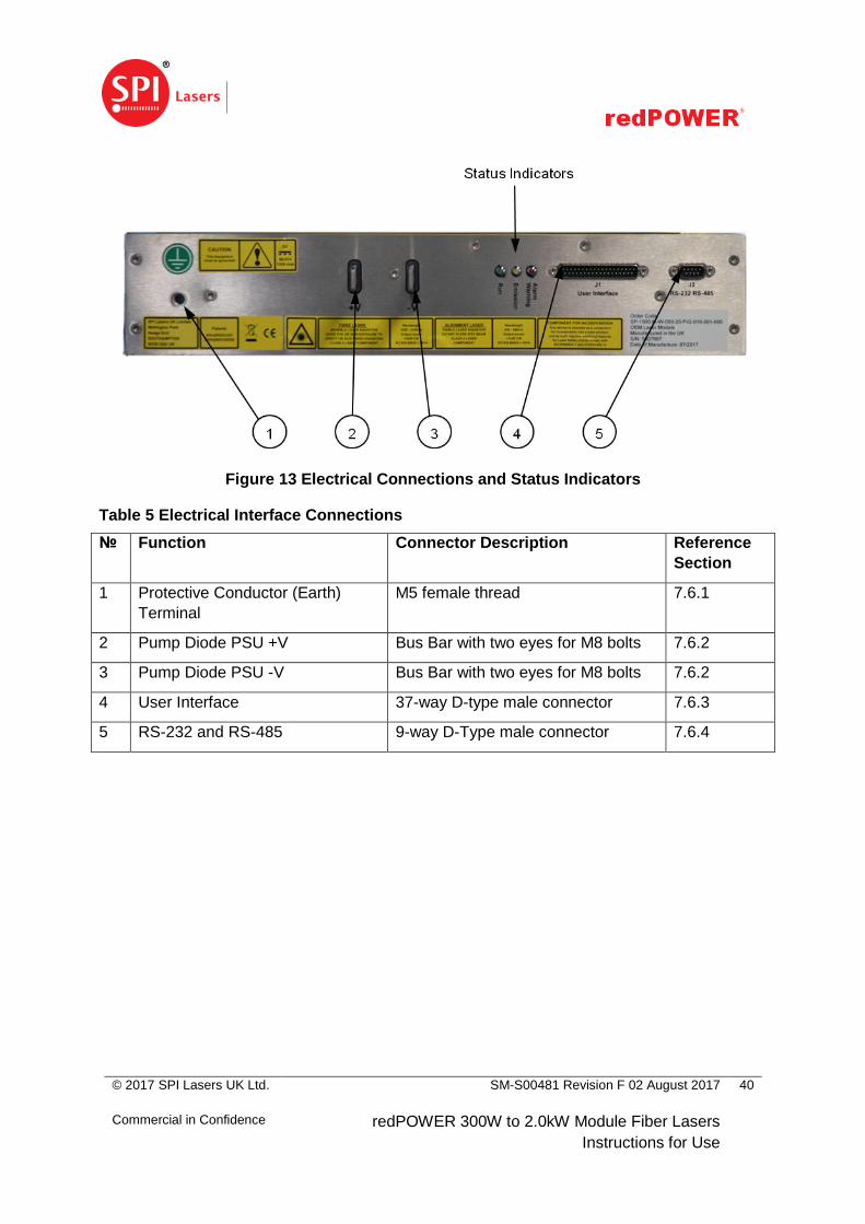
The connectors, mounted on the rear panel of the Laser as shown in Figure 13, are:
Bus bars – DC Pump Diode Supply
This is the DC power input to the pump diodes. Further details of the power supply
requirements are given in Section 11.3.1.
37-way D-type male connector – User Interface
This connector carries the main analogue and logic connections to the laser, and the
CAN bus serial interface.
It is used to enable, control and monitor the laser.
The FCMS circuit in the BDO is made available this connector. It must be monitored by
an external safety rated circuit provided by the Laser Integrator.
9-way D-Type male connector – serial interfaces
RS-232 and RS-485 serial interfaces.
The connector positions on the rear panel are shown in Figure 13, in which the head of the
arrow indicates pin 1. Table 5 give references to the sections in which the pinout and details of
the signals on each connector are given.
© 2017 SPI Lasers UK Ltd.
Commercial in Confidence
SM-S00481 Revision F 02 August 2017
redPOWER 300W to 2.0kW Module Fiber Lasers
Instructions for Use
40
Figure 13 Electrical Connections and Status Indicators
Table 5 Electrical Interface Connections
№ Function Connector Description Reference
Section
1 Protective Conductor (Earth)
Terminal
M5 female thread 7.6.1
2 Pump Diode PSU +V Bus Bar with two eyes for M8 bolts 7.6.2
3 Pump Diode PSU -V Bus Bar with two eyes for M8 bolts 7.6.2
4 User Interface 37-way D-type male connector 7.6.3
5 RS-232 and RS-485 9-way D-Type male connector 7.6.4
© 2017 SPI Lasers UK Ltd.
Commercial in Confidence
SM-S00481 Revision F 02 August 2017
redPOWER 300W to 2.0kW Module Fiber Lasers
Instructions for Use
41
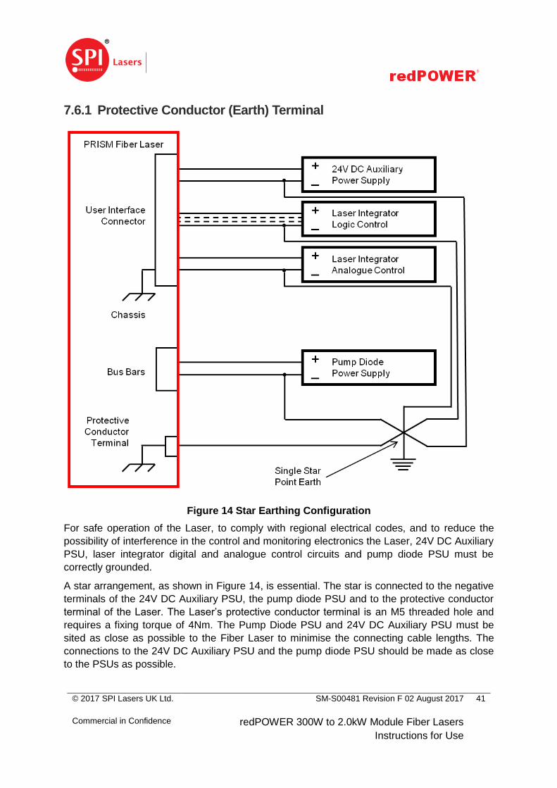
7.6.1 Protective Conductor (Earth) Terminal
Figure 14 Star Earthing Configuration
For safe operation of the Laser, to comply with regional electrical codes, and to reduce the
possibility of interference in the control and monitoring electronics the Laser, 24V DC Auxiliary
PSU, laser integrator digital and analogue control circuits and pump diode PSU must be
correctly grounded.
A star arrangement, as shown in Figure 14, is essential. The star is connected to the negative
terminals of the 24V DC Auxiliary PSU, the pump diode PSU and to the protective conductor
terminal of the Laser. The Laser’s protective conductor terminal is an M5 threaded hole and
requires a fixing torque of 4Nm. The Pump Diode PSU and 24V DC Auxiliary PSU must be
sited as close as possible to the Fiber Laser to minimise the connecting cable lengths. The
connections to the 24V DC Auxiliary PSU and the pump diode PSU should be made as close
to the PSUs as possible.
© 2017 SPI Lasers UK Ltd.
Commercial in Confidence
SM-S00481 Revision F 02 August 2017
redPOWER 300W to 2.0kW Module Fiber Lasers
Instructions for Use
42
The protective conductor shall support the maximum short-circuit current of the pump diode
PSU.
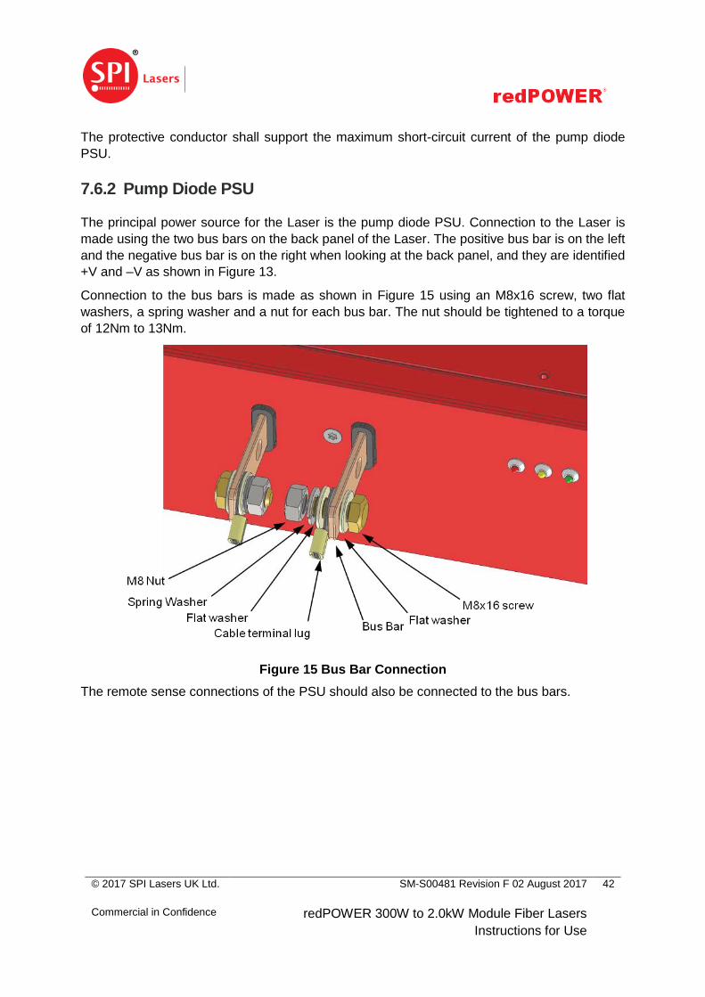
7.6.2 Pump Diode PSU
The principal power source for the Laser is the pump diode PSU. Connection to the Laser is
made using the two bus bars on the back panel of the Laser. The positive bus bar is on the left
and the negative bus bar is on the right when looking at the back panel, and they are identified
+V and –V as shown in Figure 13.
Connection to the bus bars is made as shown in Figure 15 using an M8x16 screw, two flat
washers, a spring washer and a nut for each bus bar. The nut should be tightened to a torque
of 12Nm to 13Nm.
Figure 15 Bus Bar Connection
The remote sense connections of the PSU should also be connected to the bus bars.

© 2017 SPI Lasers UK Ltd.
Commercial in Confidence
SM-S00481 Revision F 02 August 2017
redPOWER 300W to 2.0kW Module Fiber Lasers
Instructions for Use
43
7.6.3 User Interface
Figure 16 User Interface Connector
The connector is a 37-way D-type male connector and has
connections for the auxiliary power supply
connections for the alignment laser power supply (if alignment laser fitted)
logic inputs and outputs
analogue inputs and outputs
FCMS connections
The pinout and functions of the connections are given in Table 6. A fully screened, high quality
cable should be used. SPI Lasers recommends a cable from the L-com series CSMN37.
Most of the logic connections are set up for operation with 24V PLC controllers. Logic lines are
set HIGH by applying a voltage in the range 5.0 to 24.0V and set LOW by applying a voltage
in the range 0.0 to 4.0V. These logic levels are illustrated in Figure 17. Logic outputs have the
voltage level of the auxiliary power supply.
© 2017 SPI Lasers UK Ltd.
Commercial in Confidence
SM-S00481 Revision F 02 August 2017
redPOWER 300W to 2.0kW Module Fiber Lasers
Instructions for Use
44
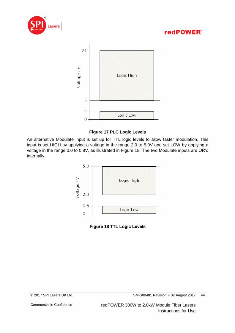
Figure 17 PLC Logic Levels
An alternative Modulate input is set up for TTL logic levels to allow faster modulation. This
input is set HIGH by applying a voltage in the range 2.0 to 5.0V and set LOW by applying a
voltage in the range 0.0 to 0.8V, as illustrated in Figure 18. The two Modulate inputs are OR’d
internally.
Figure 18 TTL Logic Levels
© 2017 SPI Lasers UK Ltd.
Commercial in Confidence
SM-S00481 Revision F 02 August 2017
redPOWER 300W to 2.0kW Module Fiber Lasers
Instructions for Use
45
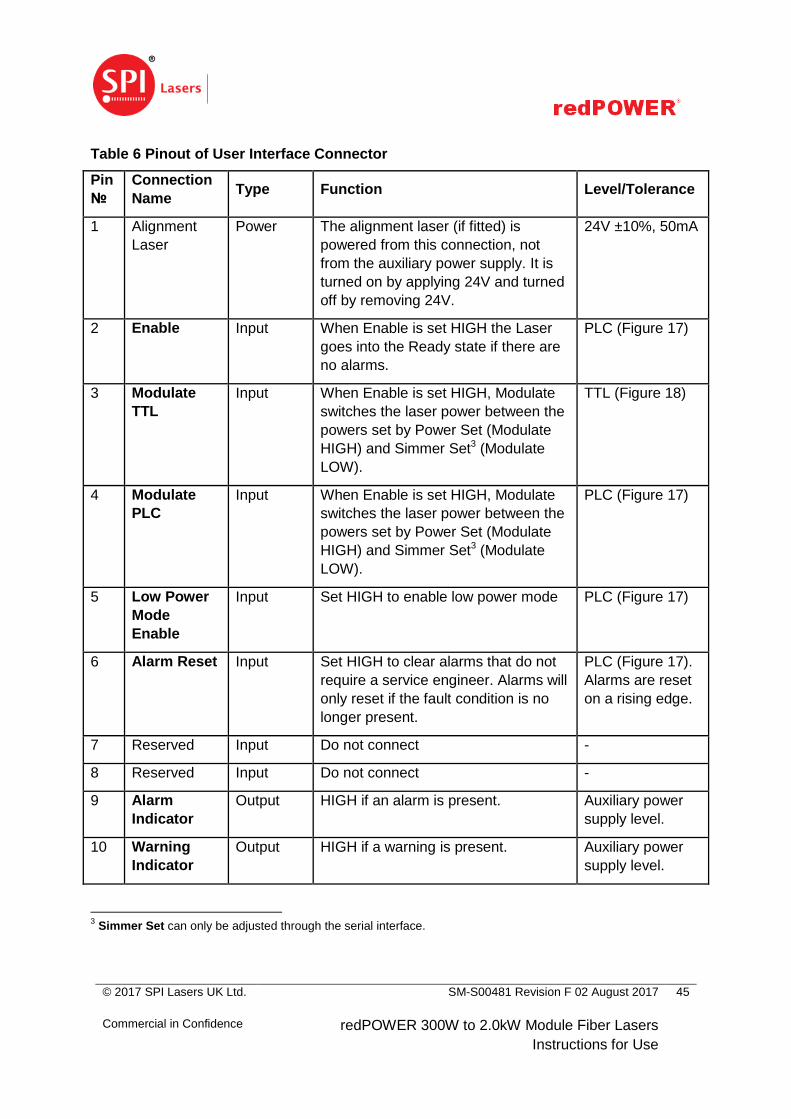
Table 6 Pinout of User Interface Connector
Pin
№
Connection
Name Type Function Level/Tolerance
1 Alignment
Laser
Power The alignment laser (if fitted) is
powered from this connection, not
from the auxiliary power supply. It is
turned on by applying 24V and turned
off by removing 24V.
24V ±10%, 50mA
2 Enable Input When Enable is set HIGH the Laser
goes into the Ready state if there are
no alarms.
PLC (Figure 17)
3 Modulate
TTL
Input When Enable is set HIGH, Modulate
switches the laser power between the
powers set by Power Set (Modulate
HIGH) and Simmer Set3 (Modulate
LOW).
TTL (Figure 18)
4 Modulate
PLC
Input When Enable is set HIGH, Modulate
switches the laser power between the
powers set by Power Set (Modulate
HIGH) and Simmer Set3 (Modulate
LOW).
PLC (Figure 17)
5 Low Power
Mode
Enable
Input Set HIGH to enable low power mode PLC (Figure 17)
6 Alarm Reset Input Set HIGH to clear alarms that do not
require a service engineer. Alarms will
only reset if the fault condition is no
longer present.
PLC (Figure 17).
Alarms are reset
on a rising edge.
7 Reserved Input Do not connect -
8 Reserved Input Do not connect -
9 Alarm
Indicator
Output HIGH if an alarm is present. Auxiliary power
supply level.
10 Warning
Indicator
Output HIGH if a warning is present. Auxiliary power
supply level.
3 Simmer Set can only be adjusted through the serial interface.

© 2017 SPI Lasers UK Ltd.
Commercial in Confidence
SM-S00481 Revision F 02 August 2017
redPOWER 300W to 2.0kW Module Fiber Lasers
Instructions for Use
46
Pin
№
Connection
Name Type Function Level/Tolerance
11 Ready Output HIGH indicates that the laser is ready
to emit.
Auxiliary power
supply level.
12 Emitting Output HIGH indicates that the laser is
emitting. Note that if Power Set is
small or zero, power may not be
emitted.
Auxiliary power
supply level.
13 Status 1 Output Status bit. LSB Auxiliary power
supply level.
14 Status 2 Output Status bit Auxiliary power
supply level.
15 Status 3 Output Status bit Auxiliary power
supply level.
16 Status 4 Output Status bit Auxiliary power
supply level.
17 Status 5 Output Status bit. MSB Auxiliary power
supply level.
18 Auxiliary
Power
Supply +ve
Power +24V to power control and monitoring
electronics
24V ±5%, 500mA
19 Auxiliary
Power
Supply +ve
Power +24V to power control and monitoring
electronics
24V ±5%, 500mA
20 Reserved Output Do not connect -
21 Reserved Output Do not connect -
22 Reserved I/O Do not connect -
23 Reserved I/O Do not connect -
24 Ground Ground - -
25 Power Set Input -
Analogue
0-10V differential analogue input to
set the power level.
0-10V with
respect to pin 26.
26 Analogue
Input Ground
Ground - -
27 Reserved Output Do not connect -
© 2017 SPI Lasers UK Ltd.
Commercial in Confidence
SM-S00481 Revision F 02 August 2017
redPOWER 300W to 2.0kW Module Fiber Lasers
Instructions for Use
47
Pin
№
Connection
Name Type Function Level/Tolerance
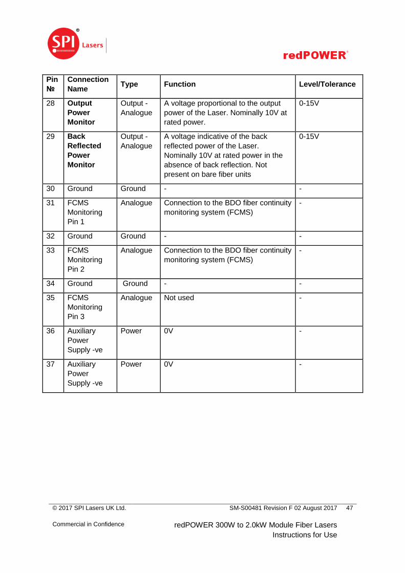
28 Output
Power
Monitor
Output -
Analogue
A voltage proportional to the output
power of the Laser. Nominally 10V at
rated power.
0-15V
29 Back
Reflected
Power
Monitor
Output -
Analogue
A voltage indicative of the back
reflected power of the Laser.
Nominally 10V at rated power in the
absence of back reflection. Not
present on bare fiber units
0-15V
30 Ground Ground - -
31 FCMS
Monitoring
Pin 1
Analogue Connection to the BDO fiber continuity
monitoring system (FCMS)
-
32 Ground Ground - -
33 FCMS
Monitoring
Pin 2
Analogue Connection to the BDO fiber continuity
monitoring system (FCMS)
-
34 Ground Ground - -
35 FCMS
Monitoring
Pin 3
Analogue Not used -
36 Auxiliary
Power
Supply -ve
Power 0V -
37 Auxiliary
Power
Supply -ve
Power 0V -
© 2017 SPI Lasers UK Ltd.
Commercial in Confidence
SM-S00481 Revision F 02 August 2017
redPOWER 300W to 2.0kW Module Fiber Lasers
Instructions for Use
48
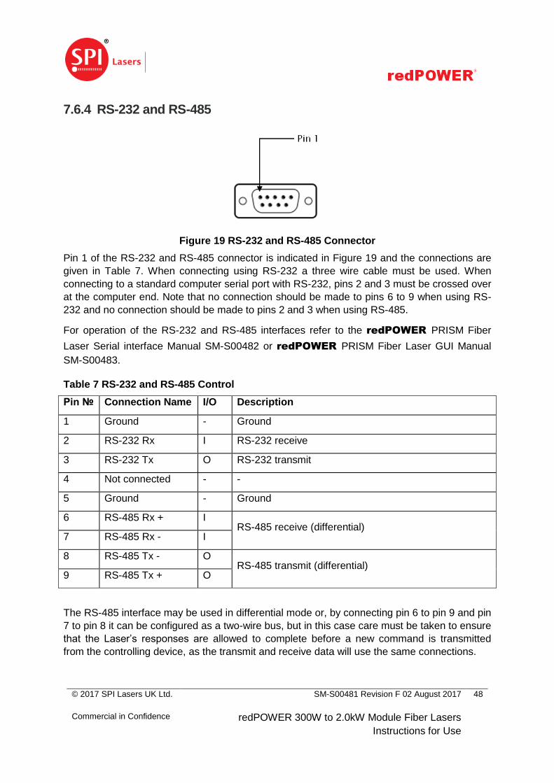
7.6.4 RS-232 and RS-485
Figure 19 RS-232 and RS-485 Connector
Pin 1 of the RS-232 and RS-485 connector is indicated in Figure 19 and the connections are
given in Table 7. When connecting using RS-232 a three wire cable must be used. When
connecting to a standard computer serial port with RS-232, pins 2 and 3 must be crossed over
at the computer end. Note that no connection should be made to pins 6 to 9 when using RS-
232 and no connection should be made to pins 2 and 3 when using RS-485.
For operation of the RS-232 and RS-485 interfaces refer to the redPOWER PRISM Fiber
Laser Serial interface Manual SM-S00482 or redPOWER PRISM Fiber Laser GUI Manual
SM-S00483.
Table 7 RS-232 and RS-485 Control
Pin № Connection Name I/O Description
1 Ground - Ground
2 RS-232 Rx I RS-232 receive
3 RS-232 Tx O RS-232 transmit
4 Not connected - -
5 Ground - Ground
6 RS-485 Rx + I RS-485 receive (differential)
7 RS-485 Rx - I
8 RS-485 Tx - O RS-485 transmit (differential)
9 RS-485 Tx + O
The RS-485 interface may be used in differential mode or, by connecting pin 6 to pin 9 and pin
7 to pin 8 it can be configured as a two-wire bus, but in this case care must be taken to ensure
that the Laser’s responses are allowed to complete before a new command is transmitted
from the controlling device, as the transmit and receive data will use the same connections.
© 2017 SPI Lasers UK Ltd.
Commercial in Confidence
SM-S00481 Revision F 02 August 2017
redPOWER 300W to 2.0kW Module Fiber Lasers
Instructions for Use
49
7.6.5 Connection to Interlock and Emergency Stop System
WARNING: The PRISM Fiber Laser does not control the pump
power supply and has no safety function to de-energise or control
the pump diodes or the output power.
Failure to provide external safety systems may result in exposure to
harmful levels of radiation.
It is the responsibility of the Laser Integrator to provide an integrator safety circuit, constructed
from components approved to the relevant standards, to make certain that electrical power is
removed to ensure laser safety. It is understood that this will be done in a manner certified to
the required national and international laws, rules, statutes and standards. This safety circuit
must only allow the Laser to be enabled when the industrial laser machine into which the
Laser is incorporated is in a state safe for laser emission. It must disable the Laser to make
the industrial laser machine safe both as required in normal operation and after activation of
the emergency stop system.
With appropriate monitoring of the FCMS, a fiber break or cable severance, an unmated
connector or optical connector over temperature condition can be detected and used to shut
down the Laser. The monitoring and shut down circuits are not included in the Laser.
The integrator safety circuit must include the FCMS such that if there is no continuity between
the FCMS pins, 33 and 35, on the user interface connector (see Section 7.6.3.) the Laser is
disabled and the industrial laser machine is put in a safe state.
The resistance of the circuit depends on the BDO length and is minimum 3, typically 4.5 and
maximum 6 ohms per metre. The circuit is insulated from earth (ground) and is only suitable
for SELV circuits, maximum 25V AC or 60V DC. The minimum recommended voltage is 5V
and minimum current is 10mA, to ensure reliable operation of the temperature switches. The
maximum permissible current is 50mA.
All applicable safety requirements for the intended market must be met prior to allowing the
Laser to enter service as part of an integrated laser system.
7.7 Routing the Beam Delivery Optic
CAUTION: If damage to the conduit or optical connector is
suspected, stop using the PRISM Fiber Laser and contact SPI
Lasers immediately.
Failure to do so may result in exposure to harmful levels of
radiation.
BDOs and their optical connectors are precision parts.
Avoid contamination and mechanical stress when handling.

© 2017 SPI Lasers UK Ltd.
Commercial in Confidence
SM-S00481 Revision F 02 August 2017
redPOWER 300W to 2.0kW Module Fiber Lasers
Instructions for Use
50
Avoid shocks and impacts on optical connectors.
Avoid pulling, twisting and over-bending of the conduit.
Beam delivery optics are less robust than electrical cables, although superficially they look
similar. If BDOs are treated and handled as electrical cables, they will fail prematurely. BDO
replacement can be both time-consuming and expensive.
Avoid kinking and twisting the conduit by unrolling the coil, rather than pulling it straight.
If the BDO is led through openings, the openings must be sufficiently large that the optical
connector with protective cap can be led through without applying any force.
In static applications (where BDO and process head do not move):
The BDO may be routed alongside power, water or control cables provided these do
not impose stresses or strains on the conduit.
The conduit must not be bent tighter than the minimum bend radius at any point along
the route. (Refer to Table 26.)
The maximum tensile loading must not be exceeded. (Refer to Table 26.)
The conduit must be supported at points along its length, at intervals no greater than
3m, to prevent gross movements under its own weight during the production
sequence.
At the support points, the conduit must be held using mechanical parts which prevent
bends tighter than the minimum bend radius and which do not apply a compressive
force on the conduit.
The external surface of the conduit must be prevented from rubbing or abrading at
support points or on any other parts in the workstation (e.g. jigs, fixtures, production
parts, workstation walls, floors, robot parts).
In dynamic applications (where BDO and process head move), additionally:
The BDO must be routed separately from power, water and control cables.
The BDO must be held off the floor and routed along a path so that the conduit is not
bent tighter than the minimum bend radius at any point along its length all through the
production sequence.
The conduit must never be pulled tight at any point along its length during the
production sequence.
If a balancer is used, tie the conduit to the rope of the balancer so that:
o the rope takes the tensile loading and not the optical connector.
o the conduit has sufficient slack for all kinds of robot motions without bending
below the minimum bend radius.
© 2017 SPI Lasers UK Ltd.
Commercial in Confidence
SM-S00481 Revision F 02 August 2017
redPOWER 300W to 2.0kW Module Fiber Lasers
Instructions for Use
51
Acceleration and deceleration of the BDO and process head must be kept to a
minimum consistent with achieving process cycle time.
At BDO installation and periodically during operation (e.g. once per shift), a dry run of
the production sequence should be made. The BDO motion should be checked to
ensure that the routing still complies with the points of good practice above.
7.8 Connecting the PIPA-Q Optical Connector to the Process Head
CAUTION: The protective cap placed on the optical connector is
intended to protect the connector from contamination during
shipping and when the PRISM Fiber Laser is not in use for
extended periods, and to prevent the FCMS circuit from being
accidentally closed. It MUST NOT be treated as a beam stop.
Operating the Laser with the protective cap in place may result in
damage to the Laser. In addition, due to the elevated temperatures
associated with operating the Laser at high power with the
protective cap in place, contact may lead to personal injury.
CAUTION: The protective tape attached to the optical connector is
intended to protect the connector from contamination during
shipping.
Operating the PRISM Fiber Laser with the protective tape in place
may result in damage to the Laser.
Each optical connector change incurs the risk of contaminating or damaging the connector.
Therefore optical connectors should only be changed when required and the local
environment should be as clean and dust free as possible to avoid introducing debris into the
process head.
The protective cap and protective tape must only be removed after the BDO is routed and
immediately before the optical connector is inserted into the process head. Remove the
protective cap slowly holding the optical connector downwards to avoid contamination settling
on the window.
Do not grease optical connectors
Keep the optical connector facing downwards when uncovered and not installed.
Do not touch the window
The optical connector must not be subjected to forces caused by dropping, impacting or
collision with heavy objects.
Optical connectors must be inspected, and cleaned if necessary, before being reinserted. See
Section 9.3.
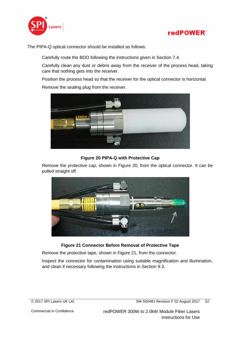
© 2017 SPI Lasers UK Ltd.
Commercial in Confidence
SM-S00481 Revision F 02 August 2017
redPOWER 300W to 2.0kW Module Fiber Lasers
Instructions for Use
52
The PIPA-Q optical connector should be installed as follows:
Carefully route the BDO following the instructions given in Section 7.4.
Carefully clean any dust or debris away from the receiver of the process head, taking
care that nothing gets into the receiver.
Position the process head so that the receiver for the optical connector is horizontal.
Remove the sealing plug from the receiver.
Figure 20 PIPA-Q with Protective Cap
Remove the protective cap, shown in Figure 20, from the optical connector. It can be
pulled straight off.
Figure 21 Connector Before Removal of Protective Tape
Remove the protective tape, shown in Figure 21, from the connector.
Inspect the connector for contamination using suitable magnification and illumination,
and clean if necessary following the instructions in Section 9.3.
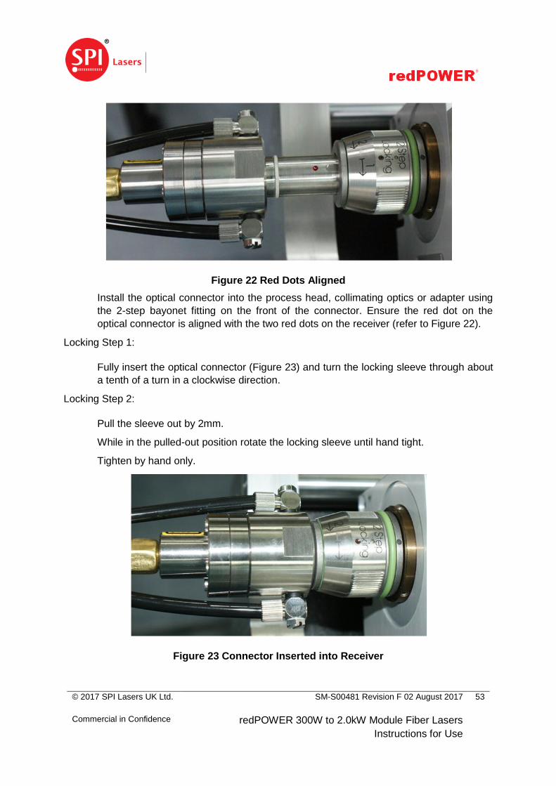
© 2017 SPI Lasers UK Ltd.
Commercial in Confidence
SM-S00481 Revision F 02 August 2017
redPOWER 300W to 2.0kW Module Fiber Lasers
Instructions for Use
53
Figure 22 Red Dots Aligned
Install the optical connector into the process head, collimating optics or adapter using
the 2-step bayonet fitting on the front of the connector. Ensure the red dot on the
optical connector is aligned with the two red dots on the receiver (refer to Figure 22).
Locking Step 1:
Fully insert the optical connector (Figure 23) and turn the locking sleeve through about
a tenth of a turn in a clockwise direction.
Locking Step 2:
Pull the sleeve out by 2mm.
While in the pulled-out position rotate the locking sleeve until hand tight.
Tighten by hand only.
Figure 23 Connector Inserted into Receiver
© 2017 SPI Lasers UK Ltd.
Commercial in Confidence
SM-S00481 Revision F 02 August 2017
redPOWER 300W to 2.0kW Module Fiber Lasers
Instructions for Use
54
7.9 Removing PIPA-Q Optical Connector from the Process Head
Each optical connector change incurs the risk of contaminating or damaging the connector.
Therefore optical connectors should only be changed when required and the local
environment should be as clean and dust free as possible to avoid introducing debris into the
process head.
Using clean, dry compressed air or nitrogen, blow away any dust from the area where the
optical connector enters the process tool.
Using a clean cloth or tissue, wipe down the area where the optical connector enters the
process tool to remove the last traces of dust or debris.
Remove the PIPA-Q optical connector from the process head using the 2-step process.
Unlocking Step 1:
Pull the locking sleeve out by 2mm.
Unlocking Step 2:
Turn the locking sleeve through about a tenth of a turn in an anticlockwise direction
and remove the optical connector.
Immediately after the optical connector is removed the protective cap must be refitted. The
process head receiver should also be plugged to prevent dust entry.

© 2017 SPI Lasers UK Ltd.
Commercial in Confidence
SM-S00481 Revision F 02 August 2017
redPOWER 300W to 2.0kW Module Fiber Lasers
Instructions for Use
55
8 Operating Instructions
WARNING: Follow the procedures and instructions described in the
following section.
Failure to do so may lead to harmful radiation exposure resulting in
personal injury and damage to the equipment.
This section describes the operation of the PRISM Fiber Laser. Before proceeding refer to all
relevant sections in these Instructions for Use covering safety, environmental and electrical
specifications, component inspection and Laser installation.
In this section the names of electrical connections are given in bold. Logic lines are set HIGH
as described in Section 7.6.3
8.1 Before Operation 8.1.1 Risk Assessment and Checks
Carry out and implement a risk assessment covering personnel and the environment
appropriate to the installation and operation of the integrated laser system.
Ensure that Lasers with bare fiber output are spliced to the appropriate SPI High
Power Combiner Module.
Ensure that the FCMS is correctly connected to the safety circuit.
Ensure that the protective cap and protective tape are removed from the optical
connector.
Ensure that the optical connector is securely mounted.
Ensure that the beam is directed towards the work piece, power meter or appropriate
beam dump.
Ensure all laser safety precautions are adhered to.
Ensure a supply of chilled water is connected to the base plate in accordance with
Section 7.5.
Ensure a supply of chilled water is connected to the optical connector in accordance
with Section 11.3.
Ensure the electrical connections are made in accordance with Section 7.6.

© 2017 SPI Lasers UK Ltd.
Commercial in Confidence
SM-S00481 Revision F 02 August 2017
redPOWER 300W to 2.0kW Module Fiber Lasers
Instructions for Use
56
8.1.2 User Training
All Users must be officially trained and authorised within their respective organisations. They
must also be fully conversant with the following:
Laser hazards, safety procedures and correct use of related safety equipment.
Hazards related to the use of Lasers for materials processing, prescribed safety
procedures and related equipment.
The contents of these Instructions for Use, and therefore the safety provisions in it.
8.2 Modes of Operation
The Laser has three modes of operation: continuous wave (CW), analogue modulation and
digital modulation. The mode of operation is controlled by the use of the Modulate logic input
and Power Set and Simmer Set levels. (Note that Simmer Set has a default value of 0% and
can only be set using a serial interface.) When Modulate is set HIGH the output power is
determined by the level set on the Power Set input, and when Modulate is set LOW the
output power is determined by the Simmer Set level.
To generate an arbitrary output (analogue modulation mode) Modulate should be set HIGH
and the arbitrary signal applied to the Power Set input. To switch rapidly between power
levels set by the Power Set and Simmer Set inputs (digital modulation mode) a logic signal
should be applied to the Modulate input.
Note that if Power Set is zero and Simmer Set is not zero, power will be emitted when
Modulate is LOW and not when Modulate is HIGH.
8.2.1 CW Mode
The output level is set by Power Set. In this mode Modulate should be set to logic HIGH. In
addition Simmer Set should be set to 0%.
8.2.2 Analogue Modulation Mode
In this mode the output of the Laser can be continuously varied using Power Set.
This mode should be used when pulse shaping and direct analogue control are required.
The power is set to that requested by Power Set when Modulate is set HIGH. If Modulate is
LOW the output power is set to that requested by Simmer Set.

© 2017 SPI Lasers UK Ltd.
Commercial in Confidence
SM-S00481 Revision F 02 August 2017
redPOWER 300W to 2.0kW Module Fiber Lasers
Instructions for Use
57
8.2.3 Digital Modulation Mode
In this mode the Laser switches between the two power levels set by Power Set and Simmer
Set. The power is set to that requested by Power Set when Modulate is set HIGH. When
Modulate is LOW the output power is set to that requested by Simmer Set.
8.2.4 Low Power Mode
Low power mode allows the laser to operate down to significantly lower average power levels
than are possible in normal mode while still maintaining stable operation. When low power
mode is enabled the maximum power available is limited to approximately 300W and stable
operation is possible down to approximately 30W. Low power mode should be used whenever
the power required is less than 300W for improved stability and avoidance of spurious output
failure alarms.
Low power mode can be used at any time with CW, analogue modulation and digital
modulation operation by setting Low Power Mode Enable HIGH.
8.2.5 Use of Simmer Set
In digital modulation mode the Laser switches between the two power levels set by Power Set
and Simmer Set. If the power level set by Simmer Set is 0%, then the first pulse in a train
may be different from subsequent ones. This first pulse non-uniformity is a well known
phenomenon which occurs when power is demanded after a period of no power, for example
when using single shots or gated pulse trains. The degree of non-uniformity is dependent on
the power, modulation frequency and duty cycle, and becomes increasingly significant at
lower powers, frequencies and duty cycles. The turn-on delay of the laser can also be
minimized using this feature. By setting Simmer Set to an empirically determined optimum
value the laser can be held just below threshold to ensure that the first pulse turns on as
quickly as the subsequent pulses and has the same energy.
Simmer Set can be adjusted from 0% to 100% which corresponds to 0% to about 20% of
rated power. A Simmer Set value of 20% is suggested as starting point for the optimisation. If
there is appreciable power when Modulate is set LOW then Simmer Set should be reduced.
If non uniformity is present, and there is no appreciable power when Modulate is set LOW,
then increase Simmer Set.
Note that if Simmer Set is not set to 0%, power will be emitted by the Laser when Modulate is
set LOW and Enable is set HIGH.

© 2017 SPI Lasers UK Ltd.
Commercial in Confidence
SM-S00481 Revision F 02 August 2017
redPOWER 300W to 2.0kW Module Fiber Lasers
Instructions for Use
58
8.3 Turning the Laser On and Off
CAUTION: If Simmer Set is not set to 0%, power will be emitted by
the Laser when Modulate is set LOW and Enable is set HIGH.
8.3.1 Enabling the Laser
Power should be applied to the Laser in the following sequence:
1. 24V DC Auxiliary PSU. The ‘Run’ status indicator will show green.
2. Allow the 24V DC Auxiliary PSU to stabilise
3. Pump Diode PSU
4. Allow the Pump Diode PSU to stabilise
To enable the Laser
5. Set Enable HIGH
The Laser will respond with HIGH on Ready and the ‘Emission’ status indicator will show
yellow. This will only occur if there are no alarms present. Alarm conditions are described in
Section 8.5.
The Laser is now enabled and power can be requested using the Power Set and Modulate
inputs. A third control, Simmer Set, can be set using the serial interface.
The two modulate inputs, Modulate TTL and Modulate PLC, are OR’d together and are not
distinguished in the following sections.
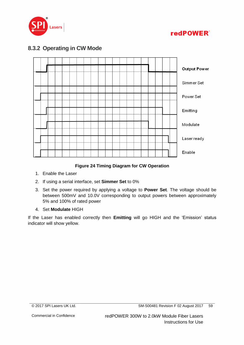
© 2017 SPI Lasers UK Ltd.
Commercial in Confidence
SM-S00481 Revision F 02 August 2017
redPOWER 300W to 2.0kW Module Fiber Lasers
Instructions for Use
59
8.3.2 Operating in CW Mode
Figure 24 Timing Diagram for CW Operation
1. Enable the Laser
2. If using a serial interface, set Simmer Set to 0%
3. Set the power required by applying a voltage to Power Set. The voltage should be
between 500mV and 10.0V corresponding to output powers between approximately
5% and 100% of rated power
4. Set Modulate HIGH
If the Laser has enabled correctly then Emitting will go HIGH and the ‘Emission’ status
indicator will show yellow.

© 2017 SPI Lasers UK Ltd.
Commercial in Confidence
SM-S00481 Revision F 02 August 2017
redPOWER 300W to 2.0kW Module Fiber Lasers
Instructions for Use
60
8.3.3 Operating in Analogue Modulation Mode
Figure 25 Timing Diagram for Operation in Analogue Modulation Mode
In this mode the output of the Laser can be continuously varied using Power Set.
This mode should be used when pulse shaping and direct analogue control is required.
1. Enable the Laser
2. If using a serial interface, set Simmer Set to 0%
3. Set Power Set to 0V
4. Set Modulate HIGH
5. Set Enable HIGH
If the Laser has enabled correctly then Emitting will go HIGH and the ‘Emission’ status
indicator will show yellow.
Set the power required by applying a variable voltage to Power Set. The voltage should be
between 500mV and 10.0V corresponding to output powers between approximately 5% and
100% of rated power.
8.3.4 Operation in Digital Modulation Mode
In this mode the Laser switches between the two power levels set by Power Set and Simmer
Set. The power is set to that requested by Power Set when Modulate is set HIGH. When
Modulate is LOW the output power is set to that requested by Simmer Set.
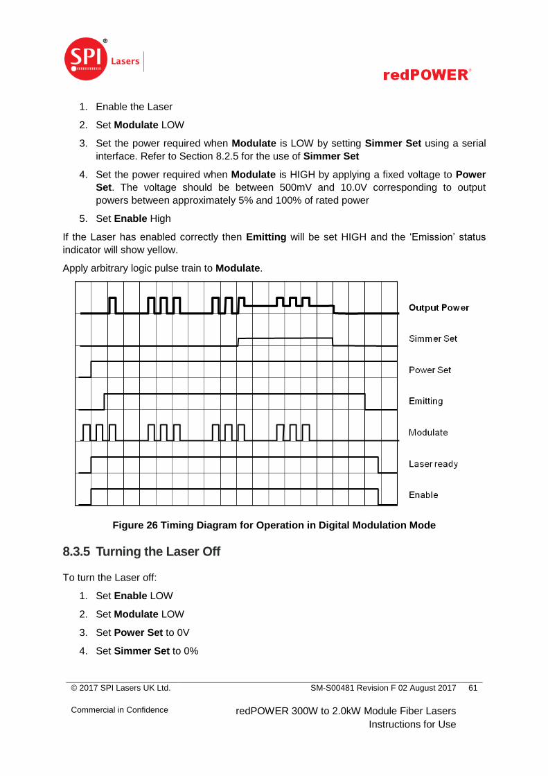
© 2017 SPI Lasers UK Ltd.
Commercial in Confidence
SM-S00481 Revision F 02 August 2017
redPOWER 300W to 2.0kW Module Fiber Lasers
Instructions for Use
61
1. Enable the Laser
2. Set Modulate LOW
3. Set the power required when Modulate is LOW by setting Simmer Set using a serial
interface. Refer to Section 8.2.5 for the use of Simmer Set
4. Set the power required when Modulate is HIGH by applying a fixed voltage to Power
Set. The voltage should be between 500mV and 10.0V corresponding to output
powers between approximately 5% and 100% of rated power
5. Set Enable High
If the Laser has enabled correctly then Emitting will be set HIGH and the ‘Emission’ status
indicator will show yellow.
Apply arbitrary logic pulse train to Modulate.
Figure 26 Timing Diagram for Operation in Digital Modulation Mode
8.3.5 Turning the Laser Off
To turn the Laser off:
1. Set Enable LOW
2. Set Modulate LOW
3. Set Power Set to 0V
4. Set Simmer Set to 0%

© 2017 SPI Lasers UK Ltd.
Commercial in Confidence
SM-S00481 Revision F 02 August 2017
redPOWER 300W to 2.0kW Module Fiber Lasers
Instructions for Use
62
The Laser will respond with LOW on Ready and Emitting, and the ‘Emission’ status indicator
will turn off. Note that Emitting will remain high for 200ms after Modulate goes low.
Remove power from the Laser in the following sequence:
1. Ensure that Enable, Modulate and Power Set are set to 0V and discharged
2. Turn off the Pump Diode PSU
3. Allow the Pump Diode PSU to discharge
4. Turn off the 24V DC Auxiliary PSU
5. Allow the 24V DC Auxiliary PSU to discharge
8.4 Turning the Alignment Laser On and Off
The alignment laser (if fitted) is turned on by applying 24V to pin 1 of the User Interface
connector. It is powered from this connection, not from the auxiliary power supply. It cannot be
turned on and off over the serial interface.
In Integrated Laser Systems in which several Lasers are combined together, the total
alignment laser power may exceed the AEL for Class 2 of IEC/EN 60825-1 if the individual
alignment lasers in some or all of the Lasers are turned on. This implementation facilitates
compliance of the Integrated Laser System to IEC/EN 60825-1 as a hardware connection is
necessary.
To determine whether an alignment laser is fitted refer to Section 5.5.
8.5 Monitoring, Alarms and Diagnostics
The state of the laser can be determined by monitoring the five status lines, pins 13 to 17 on
the user interface connector. The status should be monitored so that appropriate action can
be taken in the event of an alarm. Alarms and warnings are also indicated by the ‘Alarm
Warning’ status indicator on the rear panel. This indicator shows steady red when a warning is
present and flashing red when an alarm is present.
The states of the five status lines form a five bit word, with Status 1 the least significant bit and
Status 5 the most significant bit. Each of the 32 values and its meaning is given in Table 8.
Table 8 Meaning of Status Words
Value Meaning Action
0 Emitting (Modulation and Enable HIGH,
driver voltage present, no alarms)
Normal operation
1 Idle (Enable HIGH, driver voltage present,
no alarms)
Normal operation
2 Not Armed (Enable LOW, no alarms) Normal operation
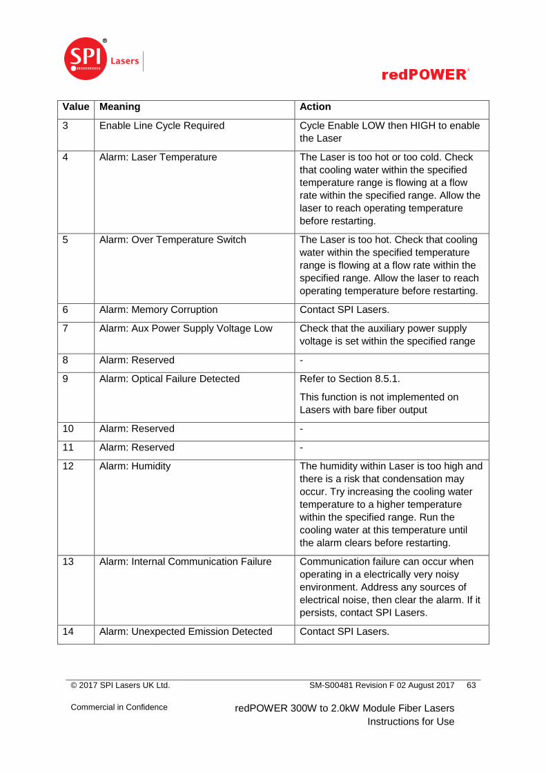
© 2017 SPI Lasers UK Ltd.
Commercial in Confidence
SM-S00481 Revision F 02 August 2017
redPOWER 300W to 2.0kW Module Fiber Lasers
Instructions for Use
63
Value Meaning Action
3 Enable Line Cycle Required Cycle Enable LOW then HIGH to enable
the Laser
4 Alarm: Laser Temperature The Laser is too hot or too cold. Check
that cooling water within the specified
temperature range is flowing at a flow
rate within the specified range. Allow the
laser to reach operating temperature
before restarting.
5 Alarm: Over Temperature Switch The Laser is too hot. Check that cooling
water within the specified temperature
range is flowing at a flow rate within the
specified range. Allow the laser to reach
operating temperature before restarting.
6 Alarm: Memory Corruption Contact SPI Lasers.
7 Alarm: Aux Power Supply Voltage Low Check that the auxiliary power supply
voltage is set within the specified range
8 Alarm: Reserved -
9 Alarm: Optical Failure Detected Refer to Section 8.5.1.
This function is not implemented on
Lasers with bare fiber output
10 Alarm: Reserved -
11 Alarm: Reserved -
12 Alarm: Humidity The humidity within Laser is too high and
there is a risk that condensation may
occur. Try increasing the cooling water
temperature to a higher temperature
within the specified range. Run the
cooling water at this temperature until
the alarm clears before restarting.
13 Alarm: Internal Communication Failure Communication failure can occur when
operating in a electrically very noisy
environment. Address any sources of
electrical noise, then clear the alarm. If it
persists, contact SPI Lasers.
14 Alarm: Unexpected Emission Detected Contact SPI Lasers.
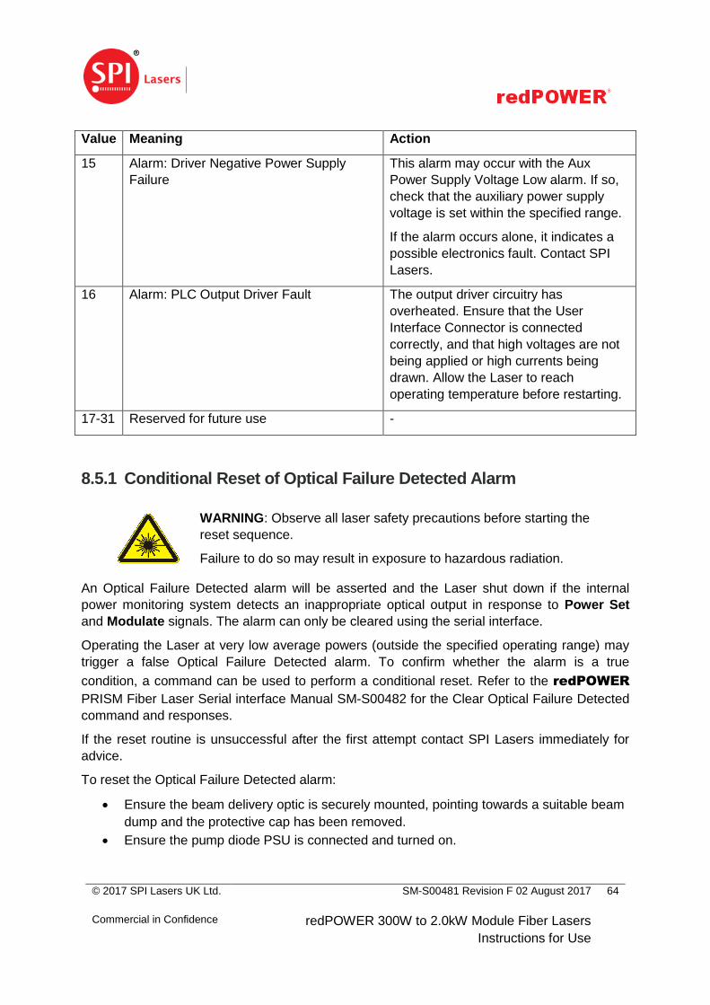
© 2017 SPI Lasers UK Ltd.
Commercial in Confidence
SM-S00481 Revision F 02 August 2017
redPOWER 300W to 2.0kW Module Fiber Lasers
Instructions for Use
64
Value Meaning Action
15 Alarm: Driver Negative Power Supply
Failure
This alarm may occur with the Aux
Power Supply Voltage Low alarm. If so,
check that the auxiliary power supply
voltage is set within the specified range.
If the alarm occurs alone, it indicates a
possible electronics fault. Contact SPI
Lasers.
16 Alarm: PLC Output Driver Fault The output driver circuitry has
overheated. Ensure that the User
Interface Connector is connected
correctly, and that high voltages are not
being applied or high currents being
drawn. Allow the Laser to reach
operating temperature before restarting.
17-31 Reserved for future use -
8.5.1 Conditional Reset of Optical Failure Detected Alarm
WARNING: Observe all laser safety precautions before starting the
reset sequence.
Failure to do so may result in exposure to hazardous radiation.
An Optical Failure Detected alarm will be asserted and the Laser shut down if the internal
power monitoring system detects an inappropriate optical output in response to Power Set
and Modulate signals. The alarm can only be cleared using the serial interface.
Operating the Laser at very low average powers (outside the specified operating range) may
trigger a false Optical Failure Detected alarm. To confirm whether the alarm is a true
condition, a command can be used to perform a conditional reset. Refer to the redPOWER
PRISM Fiber Laser Serial interface Manual SM-S00482 for the Clear Optical Failure Detected
command and responses.
If the reset routine is unsuccessful after the first attempt contact SPI Lasers immediately for
advice.
To reset the Optical Failure Detected alarm:
Ensure the beam delivery optic is securely mounted, pointing towards a suitable beam
dump and the protective cap has been removed.
Ensure the pump diode PSU is connected and turned on.
© 2017 SPI Lasers UK Ltd.
Commercial in Confidence
SM-S00481 Revision F 02 August 2017
redPOWER 300W to 2.0kW Module Fiber Lasers
Instructions for Use
65
Set modulate HIGH.
Send the Clear Optical Failure Detected command.
If the response is Alarm Cleared, confirm that reset procedure is successful.
The laser is now reset and ready for continued operation.
If the reset procedure is NOT successful contact SPI Lasers immediately for advice.
8.6 Laser Control Using PrismView
For instruction in the use of the PrismView graphical user interface to control the Laser refer to
redPOWER PRISM Fiber Laser GUI Manual SM-S00483.
8.7 Serial Control of the Laser
For the full command set refer to PRISM Fiber Laser Serial interface Manual SM-S00482.
© 2017 SPI Lasers UK Ltd.
Commercial in Confidence
SM-S00481 Revision F 02 August 2017
redPOWER 300W to 2.0kW Module Fiber Lasers
Instructions for Use
66
9 Maintenance
WARNING: Never attempt to modify internal or external
components not covered in this section.
Doing so may lead to serious personal injury, performance
degradation and premature failure.
The PRISM Fiber Laser is designed to be maintenance free. There are no parts or mechanical
items within the Laser that require replacement during the specified operating life of the Laser.
However periodic inspection of the Laser is recommended.
9.1 Periodic Inspection
The items listed below should be inspected periodically for damage which may affect the safe
operation of the Laser. The frequency of the inspection will depend on the environment in
which the Laser is installed.
The enclosure
The conduit
The optical connector
The electrical connections
The water connections and hoses
It is important that cooling water connections and hoses are regularly inspected and
maintained in order to reduce the possibility of leakage or external component failure.
Refer to Sections 7.5 for instructions regarding water cooling connection and disconnection
from the Laser.
9.2 General Cleaning
CAUTION: Do not operate the PRISM Fiber Laser if any of the
hazard warning labels are missing or damaged such that they
cannot be read properly.
Occasionally, the outside of the Laser may require cleaning to assure full and clear visibility of
the warning labels. Before cleaning disconnect the Laser from the power supplies. Clean only
with a clean damp cloth and if any labels become displaced contact SPI Lasers immediately
for replacements.
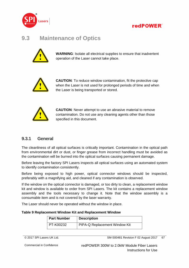
© 2017 SPI Lasers UK Ltd.
Commercial in Confidence
SM-S00481 Revision F 02 August 2017
redPOWER 300W to 2.0kW Module Fiber Lasers
Instructions for Use
67
9.3 Maintenance of Optics
WARNING: Isolate all electrical supplies to ensure that inadvertent
operation of the Laser cannot take place.
CAUTION: To reduce window contamination, fit the protective cap
when the Laser is not used for prolonged periods of time and when
the Laser is being transported or stored.
CAUTION: Never attempt to use an abrasive material to remove
contamination. Do not use any cleaning agents other than those
specified in this document.
9.3.1 General
The cleanliness of all optical surfaces is critically important. Contamination in the optical path
from environmental dirt or dust, or finger grease from incorrect handling must be avoided as
the contamination will be burned into the optical surfaces causing permanent damage.
Before leaving the factory SPI Lasers inspects all optical surfaces using an automated system
to identify contamination consistently.
Before being exposed to high power, optical connector windows should be inspected,
preferably with a magnifying aid, and cleaned if any contamination is observed.
If the window on the optical connector is damaged, or too dirty to clean, a replacement window
kit and window is available to order from SPI Lasers. The kit contains a replacement window
assembly and the tools necessary to change it. Note that the window assembly is a
consumable item and is not covered by the laser warranty.
The Laser should never be operated without the window in place.
Table 9 Replacement Window Kit and Replacement Window
Part Number Description
PT-K00232 PIPA-Q Replacement Window Kit
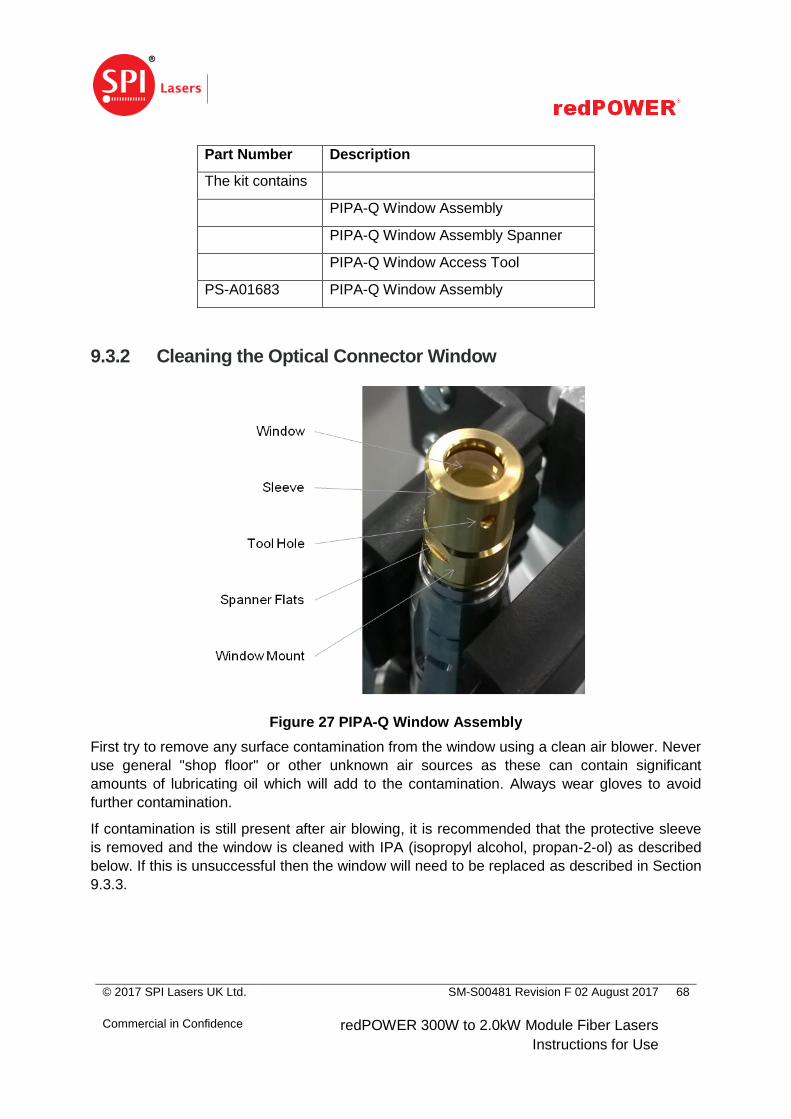
© 2017 SPI Lasers UK Ltd.
Commercial in Confidence
SM-S00481 Revision F 02 August 2017
redPOWER 300W to 2.0kW Module Fiber Lasers
Instructions for Use
68
Part Number Description
The kit contains
PIPA-Q Window Assembly
PIPA-Q Window Assembly Spanner
PIPA-Q Window Access Tool
PS-A01683 PIPA-Q Window Assembly
9.3.2 Cleaning the Optical Connector Window
Figure 27 PIPA-Q Window Assembly
First try to remove any surface contamination from the window using a clean air blower. Never
use general "shop floor" or other unknown air sources as these can contain significant
amounts of lubricating oil which will add to the contamination. Always wear gloves to avoid
further contamination.
If contamination is still present after air blowing, it is recommended that the protective sleeve
is removed and the window is cleaned with IPA (isopropyl alcohol, propan-2-ol) as described
below. If this is unsuccessful then the window will need to be replaced as described in Section
9.3.3.

© 2017 SPI Lasers UK Ltd.
Commercial in Confidence
SM-S00481 Revision F 02 August 2017
redPOWER 300W to 2.0kW Module Fiber Lasers
Instructions for Use
69
Figure 28 Removing Sleeve
1. Secure the PIPA-Q optical connector
2. Use the PIPA-Q Window Access Tool to hook into the hole in the sleeve. Turn the
sleeve to loosen. If necessary use the PIPA-Q Window Assembly Spanner (wrench) to
hold the window.
3. Unscrew and remove the sleeve by hand. Take care not to touch the window surface.
4. Inspect the exposed window for further contamination or damage. If any debris or dust
particles are present blow away with clean air.
5. If the window requires further cleaning then use soft lens cleaning paper specifically
designed for cleaning optical surfaces with IPA.
a. Place a sheet of lens cleaning paper on top of the window.
Figure 29 Placing Lens Cleaning Paper on top of the Window
b. Drip a single drop of isopropyl alcohol on the lens paper above the window.
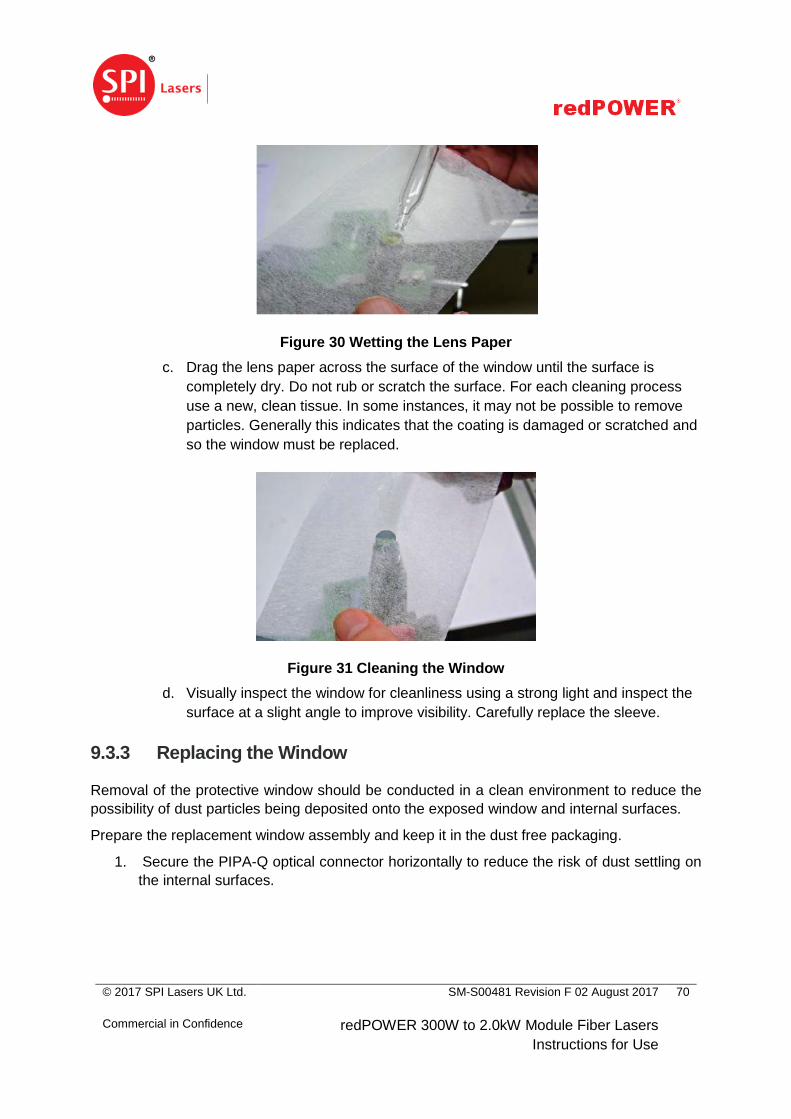
© 2017 SPI Lasers UK Ltd.
Commercial in Confidence
SM-S00481 Revision F 02 August 2017
redPOWER 300W to 2.0kW Module Fiber Lasers
Instructions for Use
70
Figure 30 Wetting the Lens Paper
c. Drag the lens paper across the surface of the window until the surface is
completely dry. Do not rub or scratch the surface. For each cleaning process
use a new, clean tissue. In some instances, it may not be possible to remove
particles. Generally this indicates that the coating is damaged or scratched and
so the window must be replaced.
Figure 31 Cleaning the Window
d. Visually inspect the window for cleanliness using a strong light and inspect the
surface at a slight angle to improve visibility. Carefully replace the sleeve.
9.3.3 Replacing the Window
Removal of the protective window should be conducted in a clean environment to reduce the
possibility of dust particles being deposited onto the exposed window and internal surfaces.
Prepare the replacement window assembly and keep it in the dust free packaging.
1. Secure the PIPA-Q optical connector horizontally to reduce the risk of dust settling on
the internal surfaces.
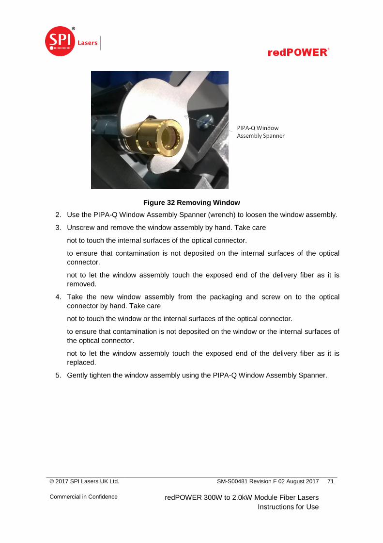
© 2017 SPI Lasers UK Ltd.
Commercial in Confidence
SM-S00481 Revision F 02 August 2017
redPOWER 300W to 2.0kW Module Fiber Lasers
Instructions for Use
71
Figure 32 Removing Window
2. Use the PIPA-Q Window Assembly Spanner (wrench) to loosen the window assembly.
3. Unscrew and remove the window assembly by hand. Take care
not to touch the internal surfaces of the optical connector.
to ensure that contamination is not deposited on the internal surfaces of the optical
connector.
not to let the window assembly touch the exposed end of the delivery fiber as it is
removed.
4. Take the new window assembly from the packaging and screw on to the optical
connector by hand. Take care
not to touch the window or the internal surfaces of the optical connector.
to ensure that contamination is not deposited on the window or the internal surfaces of
the optical connector.
not to let the window assembly touch the exposed end of the delivery fiber as it is
replaced.
5. Gently tighten the window assembly using the PIPA-Q Window Assembly Spanner.

© 2017 SPI Lasers UK Ltd.
Commercial in Confidence
SM-S00481 Revision F 02 August 2017
redPOWER 300W to 2.0kW Module Fiber Lasers
Instructions for Use
72
10 Disposal
At end of life, this Laser should be separately collected from unsorted waste with a view to
meeting the recovery and recycling targets specified in the appropriate national regulations
implementing the WEEE Directive on waste electrical and electronic equipment (WEEE) for a
product of its class.

© 2017 SPI Lasers UK Ltd.
Commercial in Confidence
SM-S00481 Revision F 02 August 2017
redPOWER 300W to 2.0kW Module Fiber Lasers
Instructions for Use
73
11 Specifications
The following section describes the operating and performance specifications of the PRISM
Fiber Laser. Included are details of the utilities required for installation and operation. Before
attempting to install or integrate the Laser, please read this section to ensure all requirements
are understood.
11.1 Operating Conditions
This Laser is designed for indoor use and to be safe when operated within the environmental
conditions given in Table 10 and at the pump diode supply voltage given in Table 12.
Table 10 Environmental Operating Conditions
Parameter Value Units
Temperature (Operating)4 5 – 45 °C
Humidity (Operating)4 5 – 85 (non-condensing) % RH
Altitude <2500 m
This Laser is sealed against dust and water ingress to IP52 to BS EN 60529:1992+A2:2013
with the exception of the electrical connectors which are rated IP50. The laser integrator
should ensure that when installed the Laser is not exposed to water.
Note that auxiliary equipment is required to operate the Laser. The environmental operating
conditions of the additional equipment must be observed.
This Laser should not be installed in a corrosive atmosphere.
This Laser should not be exposed to high levels of optical radiation, for instance laser
radiation from materials processing.
Water must not be allowed to condense on or in the Laser. It is therefore important to use a
cooling water temperature appropriate to the local humidity. The solid lines in Figure 33 cover
the permitted cooling water temperatures for the Laser5 and can be used to determine if the
atmosphere is condensing. For example, if the ambient air temperature is 25°C and the
relative humidity is 40% then there will be no condensation for any cooling water temperature
in the specified range as the condition is below the 18°C cooling water curve. However, if the
4 Refer to Figure 33 for a chart showing the relationship between relative humidity, ambient air temperature and
cooling water temperature for non-condensing operation
5 The maximum cooling water temperature for 2kW Lasers is 25°C

© 2017 SPI Lasers UK Ltd.
Commercial in Confidence
SM-S00481 Revision F 02 August 2017
redPOWER 300W to 2.0kW Module Fiber Lasers
Instructions for Use
74
ambient air temperature is 30°C and the relative humidity is 80% then the cooling water
temperature should be above 26°C, and preferably 30°C, to prevent condensation.
Figure 33 Environmental Conditions for Non-Condensing Operation
Water must not be allowed to condense on or in the optics. The dashed and solid lines in
Figure 33 cover the permitted cooling water temperatures for the PIPA-Q optical connector
and can be used to determine if the atmosphere is condensing. For example, if the ambient air
temperature is 25°C and the relative humidity is 40% then there will be no condensation for
any cooling water temperature in the specified range as the condition is below the 15°C
cooling water curve. However, if the ambient air temperature is 35°C and the relative humidity
is 80% then the cooling water temperature should be 35°C to prevent condensation.

© 2017 SPI Lasers UK Ltd.
Commercial in Confidence
SM-S00481 Revision F 02 August 2017
redPOWER 300W to 2.0kW Module Fiber Lasers
Instructions for Use
75
11.2 Non-Operating Conditions
Table 11 Non-Operating Conditions
Parameter Value Units
Temperature (Storage)6 0 to +70 °C
Humidity (Storage) 0 – 95 (non-condensing) % RH
11.3 Utility Requirements 11.3.1 Electrical Requirement
The Laser is electrically powered. Electrical power for the pump diodes is provided by an
external DC power supply and power for the internal electronics is provided by a DC auxiliary
power supply.
Table 12 Electrical Requirements
Parameter Min Typ Max Units Notes
Pump Diode Supply Voltage 48 - 51 V DC
Pump Diode
Operating Current
300W - 21 28 A
500W - 32 42 A
750W - 53 70 A
1000W - 63 84 A
1500W - 95 126 A
2000W - 126 168 A
Auxiliary PSU 22.8 25.2 V DC 0.5A Rated
An appropriately certified7 DC power supply which is adequately protected is required to
power the pump diodes in the Laser.
Table 13 gives the output requirements of a suitable PSU.
6 Below 2°C the cooling circuit must be drained to prevent freezing
7 Preferably, the power supply should be certified against at least the requirements of IEC 60950 2
nd edition
amendment A1 by a Nationally Recognised Testing Laboratory

© 2017 SPI Lasers UK Ltd.
Commercial in Confidence
SM-S00481 Revision F 02 August 2017
redPOWER 300W to 2.0kW Module Fiber Lasers
Instructions for Use
76
Table 13 Power Supply Output Capability Requirements
Parameter Min Max Units Notes
Voltage Adjustment
Range
48 51 V DC
Output
Current
300W 28 A
500W 42 A
750W 70 A
1000W 84 A
1500W 126 A
2000W 168 A
Output Load Regulation - 0.5 % 10% to 90% load variation
Output Line Regulation - 0.5 % ±10% input variation
Output Ripple and Noise - 0.5 % 20MHz measurement bandwidth
At full load, nominal input voltage
Power supply to be able to energise
≥4,000µF of load capacitance under
direct on-line load power application (cold
start)
Hold Up Time 5 - ms At full load, nominal input voltage
Transient Response - 0.5 % The input current can change from zero
to maximum in less than 5µs. If the PSU
cannot respond fast enough additional
capacitive support will be required to
ensure that the output power is
maintained over the first few milliseconds.
Stability - 0.5 % Over time and temperature
To ensure compliance with IEC/EN 6101060204-1 Safety requirements for electrical
equipment for measurement, control and laboratory use – Part 1: General Requirements, an
external switch or circuit breaker and external overcurrent protection device should be fitted.
Use of an inappropriate pump diode power supply will invalidate the warranty on the Laser.
Further information can be provided by request from SPI Lasers.
A power supply capable of providing 0.5A at 24V DC which is appropriately approved and
protected is required to power the control and monitoring circuits in the Laser.

© 2017 SPI Lasers UK Ltd.
Commercial in Confidence
SM-S00481 Revision F 02 August 2017
redPOWER 300W to 2.0kW Module Fiber Lasers
Instructions for Use
77
11.3.2 Cooling Water Requirements
The Laser requires water cooling. The base plate within the body of the laser has a dual water
cooling circuit. The PIPA-Q optical connector has a separate water cooling circuit.
Requirements for the cooling water are given in Table 14. Permitted temperature ranges and
required flow rates, together with other parameters, for the base plate and PIPA-Q optical
connector are given in Table 15 and Table 17.
Table 14 Cooling Water Requirements
Parameter Min Max Units
Appearance Clear and without sediment -
Particle size - 100 μm
Hardness (mg CaCO3 per litre) - 300 mg/l
Electrical conductivity at 25°C 22 2200 μScm-1
pH 6.5 9.0 -
Drinkable tap water is likely to meet these requirements, and water meeting the requirements
of VDI3803, Appendix B, Table B3 does.
When designing the water cooling system, the Laser Integrator should consider that:
deionised water is not permitted in the cooling circuit as the generally high levels of
dissolved O2 and CO2 in deionised water cause corrosion.
as the cooling circuit of the base plate is copper and the internal surfaces of the
PIPA-Q optical connector are nickel-plated and stainless steel, aluminium and plain
carbon or low alloy steels should not be used as galvanic corrosion may occur.
Galvanic corrosion occurs if materials with widely different electrochemical potentials
are used. Stainless steel and insulating materials (polymers) may be used.
the temperatures specified for the cooling water may sustain bacterial growth. Bacterial
growth may reduce both the flow rate and the efficiency of heat transfer as well as
being a health hazard.
hard water (water that has high mineral content) may cause scaling in the cooling
circuit reducing both the flow rate and the efficiency of heat transfer.
pre-treated water and additives for prevention of corrosion, scaling and microbial
growth are available commercially, for example from NALCO and Optishield.
where there is a need to protect the cooling water from freezing, inhibited ethylene
glycol (ethane-1,2-diol) may be added to it. SPI recommends a concentration of 25%

© 2017 SPI Lasers UK Ltd.
Commercial in Confidence
SM-S00481 Revision F 02 August 2017
redPOWER 300W to 2.0kW Module Fiber Lasers
Instructions for Use
78
by volume to protect against freezing to -10°C with a minimal drop in thermal
performance while also providing corrosion protection and serving as a bactericide.
additives may reduce the heat capacity of the water. The flow rate must be increased
to compensate. Refer to the manufacturers’ instructions and safety information for the
use of additives.
Table 15 Cooling Requirements (Base Plate)
Parameter Min Max Units Notes
Cooling Water
Temperature
18 30 ºC For most efficient operation the cooling
water temperature should be between 18ºC
and 22ºC It is important that condensation
will not occur. Refer to Section 11.1. Cooling Water
Temperature. 2000W
Lasers
18 25 ºC
Input Pressure - 6 bar
Flow Rate 10 l/min/kW The total flow through both pipes. At 25°C
water temperature. The minimum flow rate
for different inlet water temperature and
rated powers is given by Figure 34.
Pressure Drop Long
Module
- 2.5 bar
Pressure Drop Short
Module
- 2.0 bar
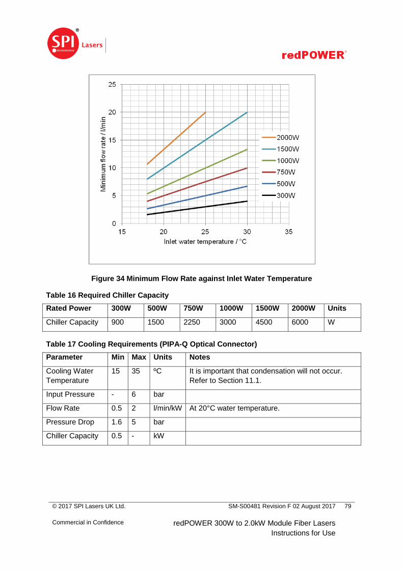
© 2017 SPI Lasers UK Ltd.
Commercial in Confidence
SM-S00481 Revision F 02 August 2017
redPOWER 300W to 2.0kW Module Fiber Lasers
Instructions for Use
79
Figure 34 Minimum Flow Rate against Inlet Water Temperature
Table 16 Required Chiller Capacity
Rated Power 300W 500W 750W 1000W 1500W 2000W Units
Chiller Capacity 900 1500 2250 3000 4500 6000 W
Table 17 Cooling Requirements (PIPA-Q Optical Connector)
Parameter Min Max Units Notes
Cooling Water
Temperature
15 35 ºC It is important that condensation will not occur.
Refer to Section 11.1.
Input Pressure - 6 bar
Flow Rate 0.5 2 l/min/kW At 20°C water temperature.
Pressure Drop 1.6 5 bar
Chiller Capacity 0.5 - kW
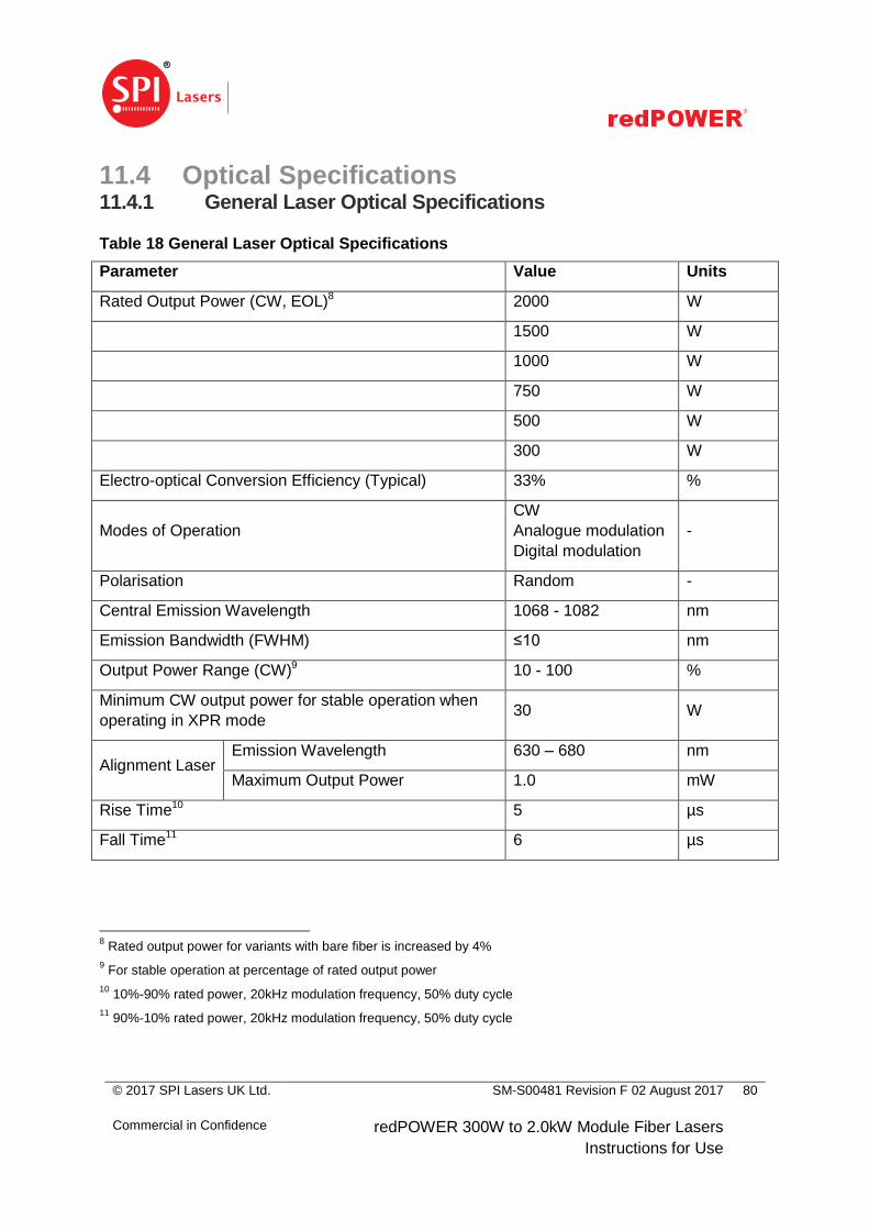
© 2017 SPI Lasers UK Ltd.
Commercial in Confidence
SM-S00481 Revision F 02 August 2017
redPOWER 300W to 2.0kW Module Fiber Lasers
Instructions for Use
80
11.4 Optical Specifications 11.4.1 General Laser Optical Specifications
Table 18 General Laser Optical Specifications
Parameter Value Units
Rated Output Power (CW, EOL)8 2000 W
1500 W
1000 W
750 W
500 W
300 W
Electro-optical Conversion Efficiency (Typical) 33% %
Modes of Operation
CW
Analogue modulation
Digital modulation
-
Polarisation Random -
Central Emission Wavelength 1068 - 1082 nm
Emission Bandwidth (FWHM) ≤10 nm
Output Power Range (CW)9 10 - 100 %
Minimum CW output power for stable operation when
operating in XPR mode 30 W
Alignment Laser Emission Wavelength 630 – 680 nm
Maximum Output Power 1.0 mW
Rise Time10 5 µs
Fall Time11 6 µs
8 Rated output power for variants with bare fiber is increased by 4%
9 For stable operation at percentage of rated output power
10 10%-90% rated power, 20kHz modulation frequency, 50% duty cycle
11 90%-10% rated power, 20kHz modulation frequency, 50% duty cycle
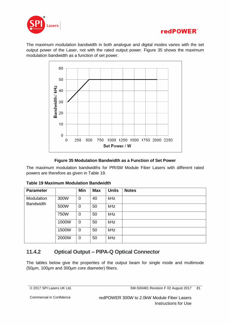
© 2017 SPI Lasers UK Ltd.
Commercial in Confidence
SM-S00481 Revision F 02 August 2017
redPOWER 300W to 2.0kW Module Fiber Lasers
Instructions for Use
81
The maximum modulation bandwidth in both analogue and digital modes varies with the set
output power of the Laser, not with the rated output power. Figure 35 shows the maximum
modulation bandwidth as a function of set power.
Figure 35 Modulation Bandwidth as a Function of Set Power
The maximum modulation bandwidths for PRISM Module Fiber Lasers with different rated
powers are therefore as given in Table 19.
Table 19 Maximum Modulation Bandwidth
Parameter Min Max Units Notes
Modulation
Bandwidth
300W 0 40 kHz
500W 0 50 kHz
750W 0 50 kHz
1000W 0 50 kHz
1500W 0 50 kHz
2000W 0 50 kHz
11.4.2 Optical Output – PIPA-Q Optical Connector
The tables below give the properties of the output beam for single mode and multimode
(50µm, 100µm and 300µm core diameter) fibers.
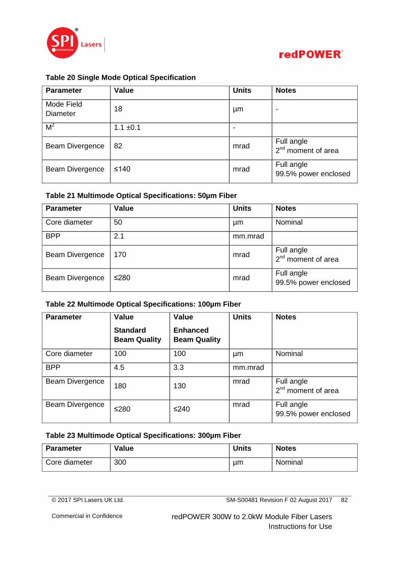
© 2017 SPI Lasers UK Ltd.
Commercial in Confidence
SM-S00481 Revision F 02 August 2017
redPOWER 300W to 2.0kW Module Fiber Lasers
Instructions for Use
82
Table 20 Single Mode Optical Specification
Parameter Value Units Notes
Mode Field
Diameter 18 µm -
M2 1.1 ±0.1 -
Beam Divergence 82 mrad Full angle
2nd moment of area
Beam Divergence ≤140 mrad Full angle
99.5% power enclosed
Table 21 Multimode Optical Specifications: 50µm Fiber
Parameter Value Units Notes
Core diameter 50 µm Nominal
BPP 2.1 mm.mrad
Beam Divergence 170 mrad Full angle
2nd moment of area
Beam Divergence ≤280 mrad Full angle
99.5% power enclosed
Table 22 Multimode Optical Specifications: 100µm Fiber
Parameter Value
Standard
Beam Quality
Value
Enhanced
Beam Quality
Units Notes
Core diameter 100 100 µm Nominal
BPP 4.5 3.3 mm.mrad
Beam Divergence 180 130
mrad Full angle
2nd moment of area
Beam Divergence ≤280 ≤240
mrad Full angle
99.5% power enclosed
Table 23 Multimode Optical Specifications: 300µm Fiber
Parameter Value Units Notes
Core diameter 300 µm Nominal
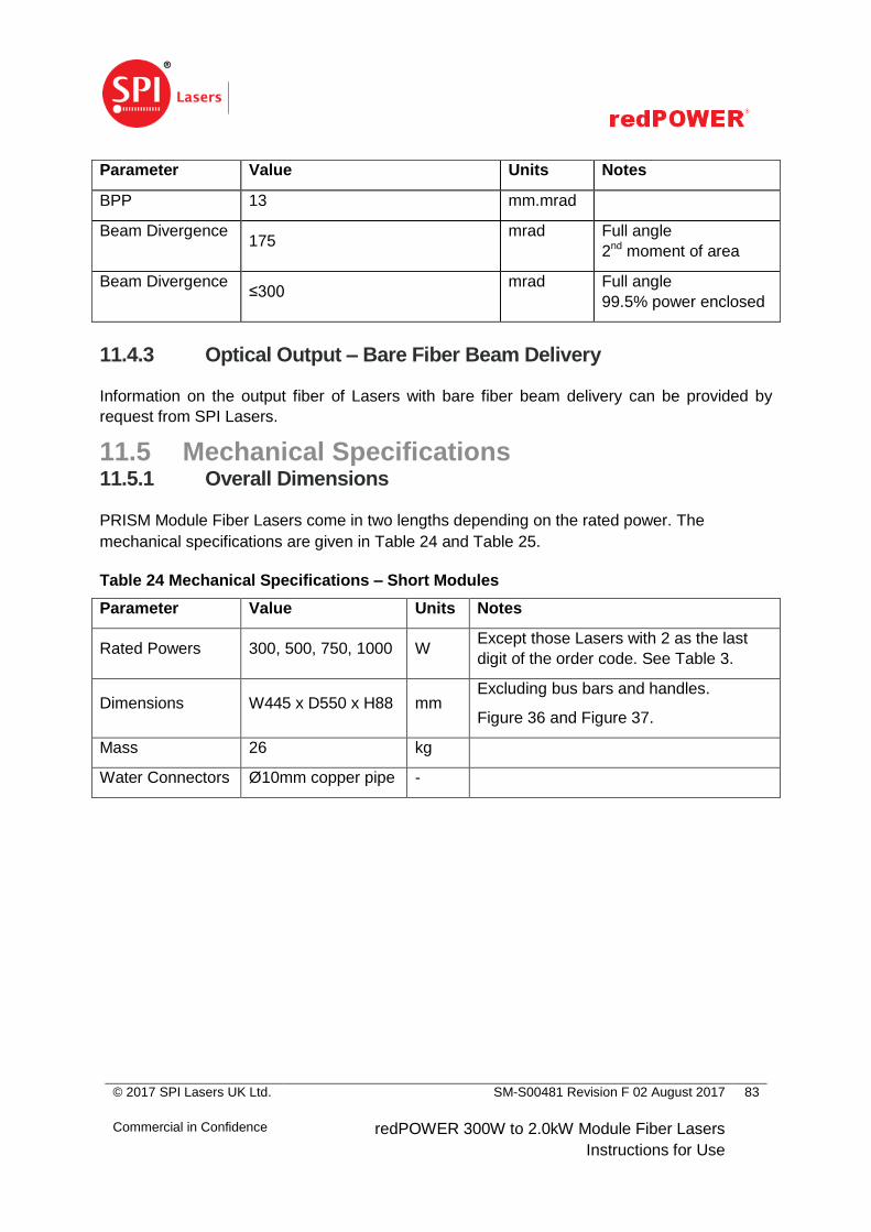
© 2017 SPI Lasers UK Ltd.
Commercial in Confidence
SM-S00481 Revision F 02 August 2017
redPOWER 300W to 2.0kW Module Fiber Lasers
Instructions for Use
83
Parameter Value Units Notes
BPP 13 mm.mrad
Beam Divergence 175
mrad Full angle
2nd moment of area
Beam Divergence ≤300
mrad Full angle
99.5% power enclosed
11.4.3 Optical Output – Bare Fiber Beam Delivery
Information on the output fiber of Lasers with bare fiber beam delivery can be provided by
request from SPI Lasers.
11.5 Mechanical Specifications 11.5.1 Overall Dimensions
PRISM Module Fiber Lasers come in two lengths depending on the rated power. The
mechanical specifications are given in Table 24 and Table 25.
Table 24 Mechanical Specifications – Short Modules
Parameter Value Units Notes
Rated Powers 300, 500, 750, 1000 W Except those Lasers with 2 as the last
digit of the order code. See Table 3.
Dimensions W445 x D550 x H88 mm Excluding bus bars and handles.
Figure 36 and Figure 37.
Mass 26 kg
Water Connectors Ø10mm copper pipe -
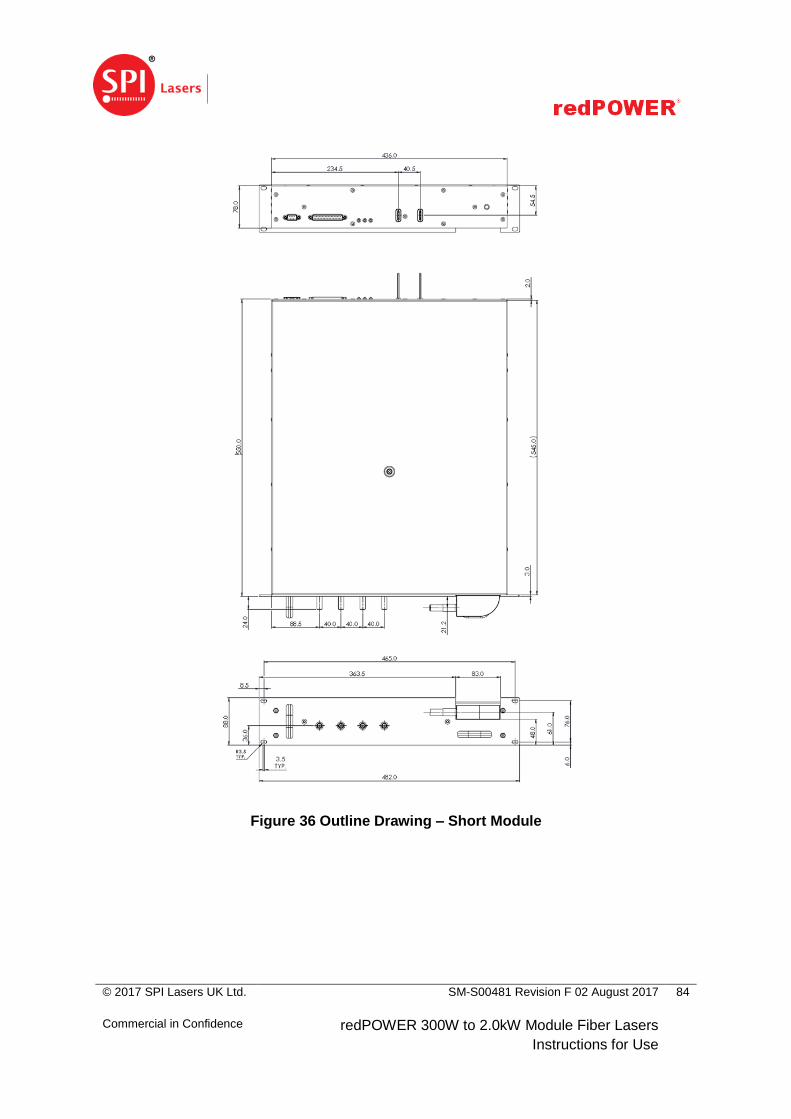
© 2017 SPI Lasers UK Ltd.
Commercial in Confidence
SM-S00481 Revision F 02 August 2017
redPOWER 300W to 2.0kW Module Fiber Lasers
Instructions for Use
84
Figure 36 Outline Drawing – Short Module
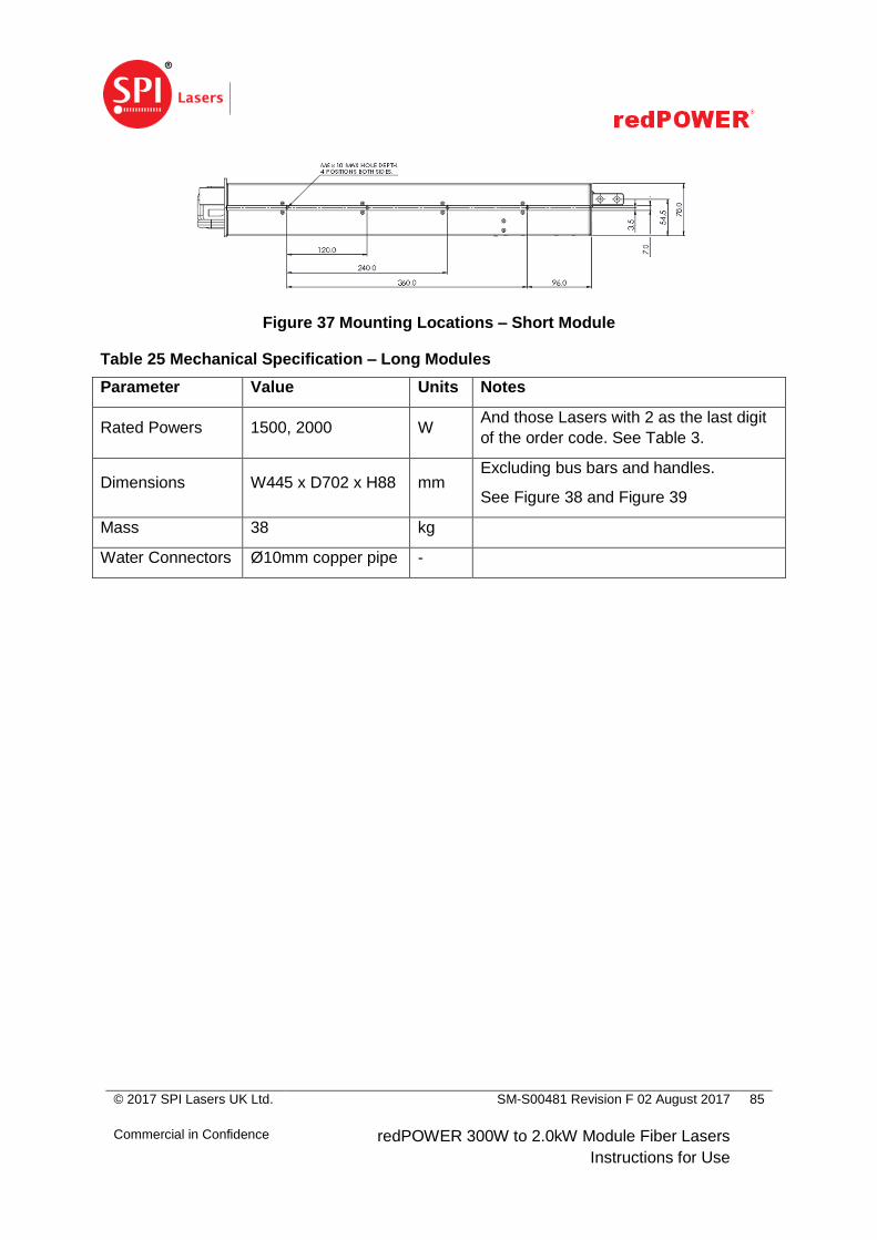
© 2017 SPI Lasers UK Ltd.
Commercial in Confidence
SM-S00481 Revision F 02 August 2017
redPOWER 300W to 2.0kW Module Fiber Lasers
Instructions for Use
85
Figure 37 Mounting Locations – Short Module
Table 25 Mechanical Specification – Long Modules
Parameter Value Units Notes
Rated Powers 1500, 2000 W And those Lasers with 2 as the last digit
of the order code. See Table 3.
Dimensions W445 x D702 x H88 mm Excluding bus bars and handles.
See Figure 38 and Figure 39
Mass 38 kg
Water Connectors Ø10mm copper pipe -
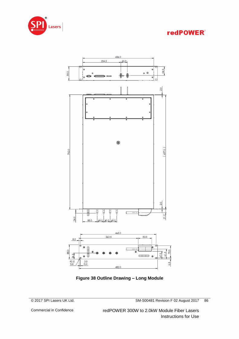
© 2017 SPI Lasers UK Ltd.
Commercial in Confidence
SM-S00481 Revision F 02 August 2017
redPOWER 300W to 2.0kW Module Fiber Lasers
Instructions for Use
86
Figure 38 Outline Drawing – Long Module
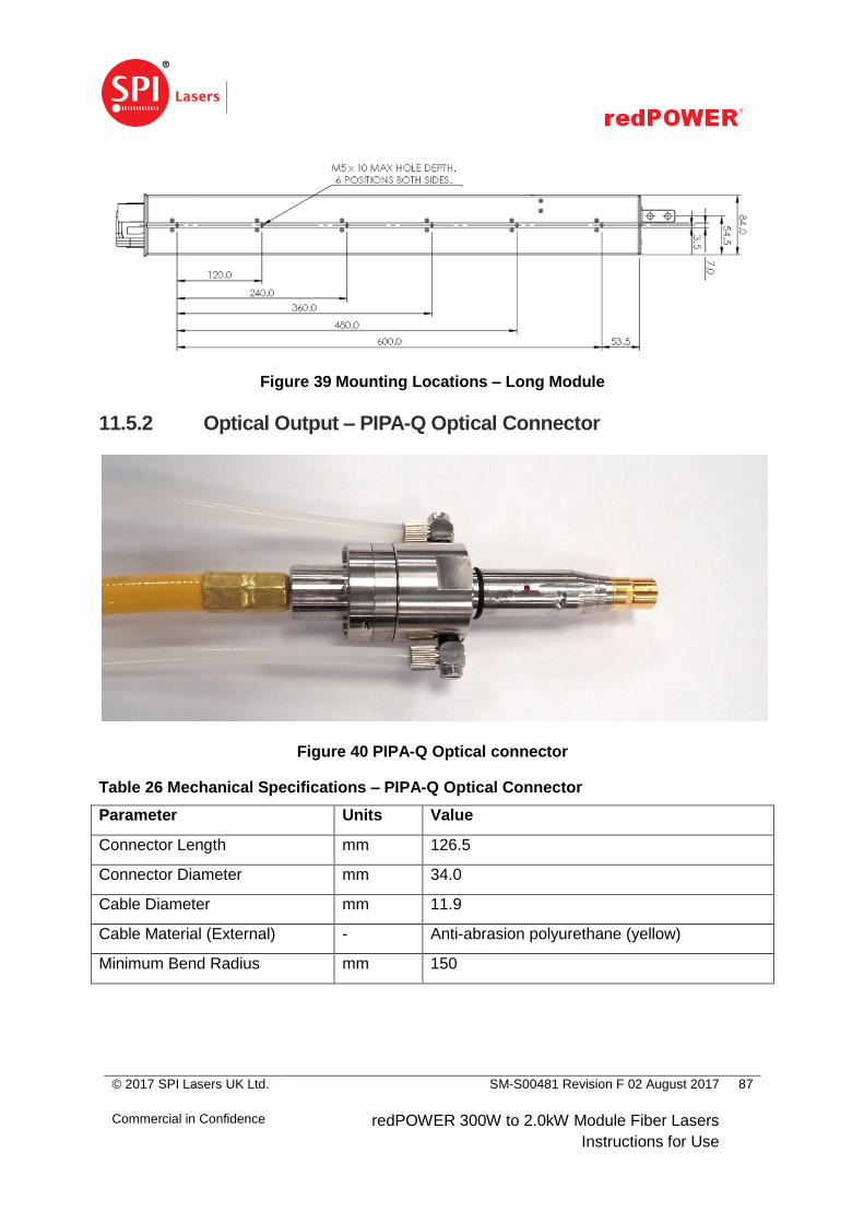
© 2017 SPI Lasers UK Ltd.
Commercial in Confidence
SM-S00481 Revision F 02 August 2017
redPOWER 300W to 2.0kW Module Fiber Lasers
Instructions for Use
87
Figure 39 Mounting Locations – Long Module
11.5.2 Optical Output – PIPA-Q Optical Connector
Figure 40 PIPA-Q Optical connector
Table 26 Mechanical Specifications – PIPA-Q Optical Connector
Parameter Units Value
Connector Length mm 126.5
Connector Diameter mm 34.0
Cable Diameter mm 11.9
Cable Material (External) - Anti-abrasion polyurethane (yellow)
Minimum Bend Radius mm 150
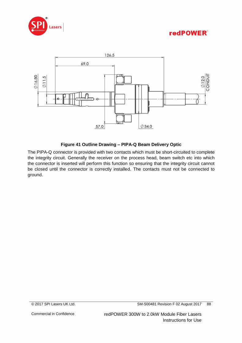
© 2017 SPI Lasers UK Ltd.
Commercial in Confidence
SM-S00481 Revision F 02 August 2017
redPOWER 300W to 2.0kW Module Fiber Lasers
Instructions for Use
88
Figure 41 Outline Drawing – PIPA-Q Beam Delivery Optic
The PIPA-Q connector is provided with two contacts which must be short-circuited to complete
the integrity circuit. Generally the receiver on the process head, beam switch etc into which
the connector is inserted will perform this function so ensuring that the integrity circuit cannot
be closed until the connector is correctly installed. The contacts must not be connected to
ground.
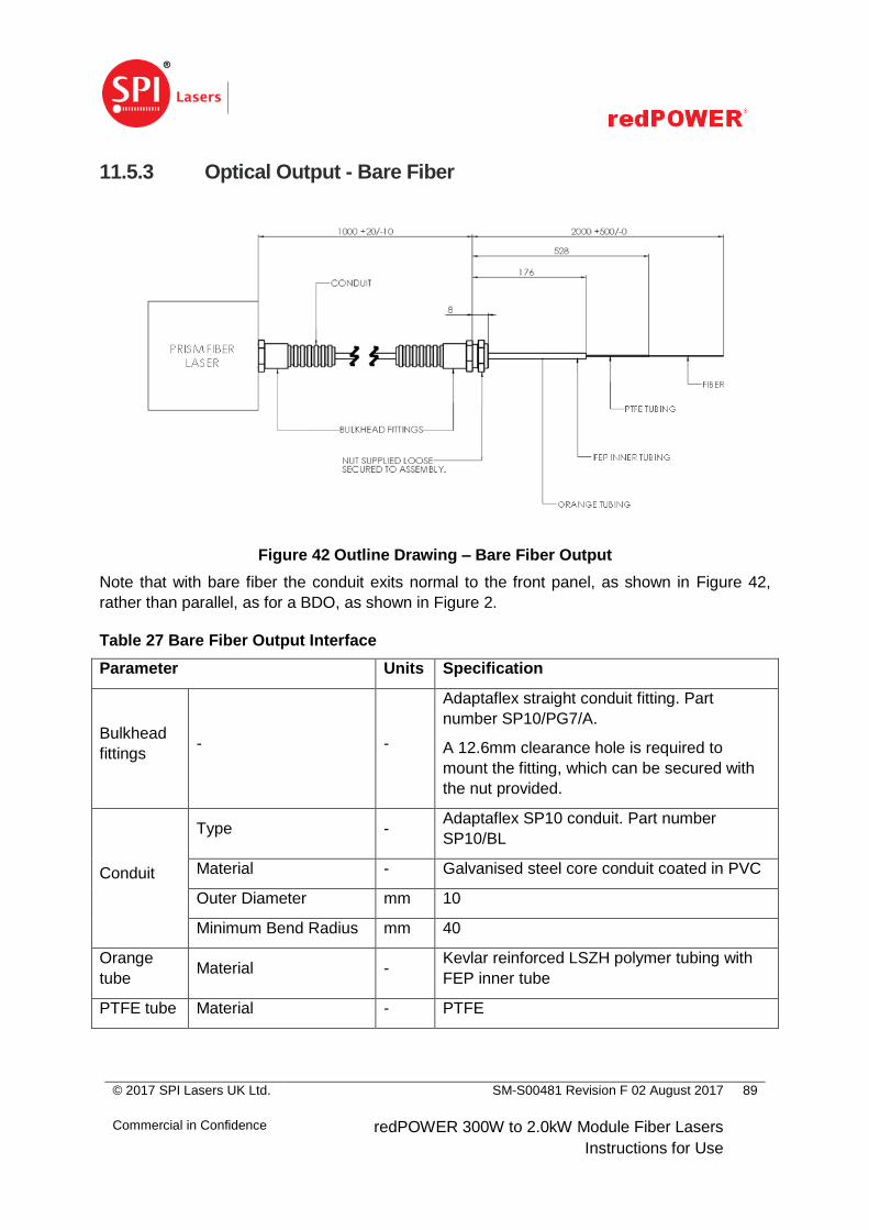
© 2017 SPI Lasers UK Ltd.
Commercial in Confidence
SM-S00481 Revision F 02 August 2017
redPOWER 300W to 2.0kW Module Fiber Lasers
Instructions for Use
89
11.5.3 Optical Output - Bare Fiber
Figure 42 Outline Drawing – Bare Fiber Output
Note that with bare fiber the conduit exits normal to the front panel, as shown in Figure 42,
rather than parallel, as for a BDO, as shown in Figure 2.
Table 27 Bare Fiber Output Interface
Parameter Units Specification
Bulkhead
fittings - -
Adaptaflex straight conduit fitting. Part
number SP10/PG7/A.
A 12.6mm clearance hole is required to
mount the fitting, which can be secured with
the nut provided.
Conduit
Type - Adaptaflex SP10 conduit. Part number
SP10/BL
Material - Galvanised steel core conduit coated in PVC
Outer Diameter mm 10
Minimum Bend Radius mm 40
Orange
tube Material -
Kevlar reinforced LSZH polymer tubing with
FEP inner tube
PTFE tube Material - PTFE

© 2017 SPI Lasers UK Ltd.
Commercial in Confidence
SM-S00481 Revision F 02 August 2017
redPOWER 300W to 2.0kW Module Fiber Lasers
Instructions for Use
90
Parameter Units Specification
Fiber
Fiber Specifications
SF21-0042 -
Further information can be provided by
request from SPI Lasers
Minimum Bend Radius mm 40
© 2017 SPI Lasers UK Ltd.
Commercial in Confidence
SM-S00481 Revision F 02 August 2017
redPOWER 300W to 2.0kW Module Fiber Lasers
Instructions for Use
91
12 General Information
12.1 Trade Marks
The SPI Lasers logo, SPI, GTWave, redPOWER, and redENERGY are trademarks
(registered or applied for) of SPI Lasers in at least one of the United States of America, the
United Kingdom, the European Community, China, and in various other territories throughout
the world. All other trademarks are the property of their registered owners.
12.2 Licensing
This Laser carries no licence by IMRA America, Inc. for pulsed operation less than 100ps.
12.3 Software
Any software forming part of this equipment should be used only for the purpose for which it
was supplied by SPI Lasers. No changes, modifications or copies (except for producing a
necessary back-up copy) shall be undertaken by the User.
SPI Lasers accepts no responsibility for equipment malfunction resulting from any of the
above actions.
12.4 Warranties
SPI Lasers makes no warranties, expressed or implied, including and without limitation
warranties as to merchantability or fitness for a particular purpose except as expressly set
forth in the standard Terms and Conditions of sale.
12.5 Copyright
Copyright SPI Lasers. All rights reserved. You may not reproduce, transmit, store in a retrieval
system or adapt this publication, in any form or by any means, without the prior written
permission of SPI Lasers, except as allowed under applicable copyright laws. The information
contained herein is confidential and is the property of SPI Lasers. No part may be reproduced,
disclosed or used except as authorised by contract or other written permission. The copyright
and the foregoing restriction on reproduction and use extend to all media in which the
information may be embodied.

© 2017 SPI Lasers UK Ltd.
Commercial in Confidence
SM-S00481 Revision F 02 August 2017
redPOWER 300W to 2.0kW Module Fiber Lasers
Instructions for Use
92
12.6 Changes
These Instructions for Use are supplied without liability for errors or omissions. SPI Lasers
reserves the right to change the information and specifications contained in these Instructions
for Use without prior notice.

© 2017 SPI Lasers UK Ltd.
Commercial in Confidence
SM-S00481 Revision F 02 August 2017
redPOWER 300W to 2.0kW Module Fiber Lasers
Instructions for Use
93
13 Contact Information
Table 28 Contact Information
UK Head Office and
Manufacturing
Facility
US Corporate Office China Office Korea Office
SPI Lasers UK
Limited SPI Lasers LLC
SPI Lasers
(Shanghai) Co., Ltd.
SPI Lasers Korea
Ltd.
6 Wellington Park
Hedge End
Southampton
SO30 2QU
UK
4000 Burton Drive
Santa Clara
CA 95054
USA
Room 108, Building 3
No. 7 Guiqing Road
Caohejing Hi-tech
Park
Shanghai 200233
China
A-1201 DAEBANG
TRIPLAON Business
Tower
1682 Jungsan-dong
Ilsandong-gu
Goyang-si
Gyeonggi-do
Republic of Korea
Tel: +44 (0)1489
779696
Tel: +1 408 454 1169 Tel: +86 (0) 21 6171
9470
Tel: +82 31 926 7580
Customer Services
Tel: +44 (0)1489 779696 - Option 5
Company Web Site
www.spilasers.com
Product Support
Tel: +44 (0)1489 779696 - Option 2
Contact your local office number
Or contact your local distributor.
© 2017 SPI Lasers UK Ltd.
Commercial in Confidence
SM-S00481 Revision F 02 August 2017
redPOWER 300W to 2.0kW Module Fiber Lasers
Instructions for Use
94
14 Customer Service
In the unlikely event that the Laser requires attention outside the scope of the maintenance
requirements as detailed in Section 9, contact SPI Lasers for advice on further on-site fault
diagnosis and/or return of the Laser. Contact information is given in Section13.
When contacting SPI Lasers, please have the following information at hand:
The order code.
The serial number.
The number of accumulated laser hours.
Typical operating parameters.
Any other relevant information (e.g. fault codes and descriptions) that would assist in
fault diagnosis.
If the Laser requires fault-diagnosis or servicing or is to be returned to SPI Lasers, it is the
system integrator’s responsibility to remove the Laser from the integrated laser system and
make it safe and, if the Laser is to be returned to SPI Lasers, to ensure that all relevant return
documentation is in place before shipment. Details of documentation requirements and copies
can be obtained where required from SPI Lasers.
The Laser must be drained of all coolant and the end caps fitted to all pipes prior to shipment.
If the Laser is shipped without the end caps fitted then any residual coolant will escape during
transit and may cause permanent damage.
Pack the Laser in the original packaging and include all original accessories and
documentation as detailed in the original inventory. The correct and original packaging should
be used to prevent damage in transit. If all or part of the original packaging is unavailable,
contact SPI Lasers for replacement items. Please take time to complete all return
documentation, which can be obtained from SPI Lasers. Accurate details, diagnosis and
comments in the documentation reduce turnaround time for repair at SPI Lasers.
On request, SPI Lasers will supply a report detailing faults found and repairs carried out
necessary to return the Laser to full operational specification.


![POMPA PIPA DENGAN VARIASI DIAMETER PIPA BAWAH1].pdfkaruniaNya, sehingga Tugas Akhir dengan judul “ Pompa Pipa Dengan Variasi Diameter Pipa Bawah “ ini dapat selesai. Tugas Akhir](https://static.fdocuments.net/doc/165x107/60078625d169ef6c32304816/pompa-pipa-dengan-variasi-diameter-pipa-bawah-1pdf-karunianya-sehingga-tugas.jpg)