RedLab WLS-TEMP en - Meilhaus Electronic … WLS... · RedLab WLS-TEMP User's Guide Introducing the...
37
Transcript of RedLab WLS-TEMP en - Meilhaus Electronic … WLS... · RedLab WLS-TEMP User's Guide Introducing the...

RedLab WLS-TEMP
Wireless-based High-Precision 8-Channel Temperature Measurement Module
User's Guide
Document Revision 1.2 E, April, 2014
© Copyright 2014, Meilhaus Electronic
3
Imprint
User’s Guide RedLab® Series
Document Revision 1.2 E Revision Date: April 2014
Meilhaus Electronic GmbH
Am Sonnenlicht 2 D-82239 Alling near Munich, Germany http://www.meilhaus.de
© Copyright 2014 Meilhaus Electronic GmbH
All rights reserved. No part of this publication may be reproduced, stored in a retrieval system, or transmitted, in any form by any means, electronic, mechanical, by photocopying, recording, or otherwise without the prior written permission of Meilhaus Electronic GmbH.
Important note: All the information included in this user’s guide were put together with utmost care and to best knowledge. However, mistakes may not have been erased completely.
For this reason, the firm Meilhaus Electronic GmbH feels obliged to point out that they cannot be take on neither any warranty (apart from the claims for warranty as agreed) nor legal responsibility or liability for consequences caused by incorrect instructions.
We would appreciate it if you inform us about any possible mistakes.
The trademark Personal Measurement Device, TracerDAQ, Universal Library, InstaCal, Harsh Environment Warranty, Measurement Computing Corporation, and the Measurement Computing logo are either trademarks or registered trademarks of Measurement Computing Corporation.
Windows, Microsoft, and Visual Studio are either trademarks or registered trademarks of Microsoft Corporation.
LabVIEW is a trademark of National Instruments.
CompactFlash is a registered trademark of SanDisk Corporation.
XBee is a trademark of MaxStream, Inc.
All other trademarks are the property of their respective owners.

4
Table of Contents Preface About this User’s Guide .......................................................................................................................6
What you will learn from this user’s guide.........................................................................................................6 Conventions in this user’s guide.........................................................................................................................6 Where to find more information .........................................................................................................................6
Chapter 1 Introducing the RedLab WLS-TEMP ...................................................................................................7
Overview: RedLab WLS-TEMP features...........................................................................................................7 Remote wireless operation................................................................................................................................................ 8
RedLab WLS-TEMP block diagram ..................................................................................................................8 Software features ................................................................................................................................................8
Chapter 2 Installing the RedLab WLS-TEMP .......................................................................................................9
What comes with your RedLab WLS-TEMP shipment?....................................................................................9 Hardware .......................................................................................................................................................................... 9 Additional documentation................................................................................................................................................. 9
Unpacking the RedLab WLS-TEMP................................................................................................................10 Installing the software ......................................................................................................................................10 Installing the RedLab WLS-TEMP ..................................................................................................................10 Configuring the RedLab WLS-TEMP..............................................................................................................11
Temperature sensors ........................................................................................................................................................11 Network parameters (remote operation) ..........................................................................................................................11
Connecting the external power supply for remote operation............................................................................12 Calibrating the RedLab WLS-TEMP ...............................................................................................................13 Warm up time ...................................................................................................................................................13
Chapter 3 Sensor Connections ...........................................................................................................................14
Screw terminal pin out......................................................................................................................................14 Sensor input terminals (C0H/C0L to C7H/C7L)..............................................................................................................15 Current excitation output terminals (±I1 to ±I4) ..............................................................................................................16 Four-wire, two sensor common terminals (4W01 to 4W67)............................................................................................16 Two sensor common terminals (IC01 to IC67)................................................................................................................16 Ground terminals (GND) .................................................................................................................................................16 Power terminals (+5V).....................................................................................................................................................16 Digital terminals (DIO0 to DIO7)....................................................................................................................................16 CJC sensors......................................................................................................................................................................16
Thermocouple connections...............................................................................................................................16 Wiring configuration........................................................................................................................................................17
RTD and thermistor connections ......................................................................................................................17 Two-wire configuration ...................................................................................................................................................18 Three-wire configuration .................................................................................................................................................19 Four-wire configuration ...................................................................................................................................................19
Semiconductor sensor measurements ...............................................................................................................20 Wiring configuration........................................................................................................................................................20
Digital I/O connections.....................................................................................................................................21 Configuring the DIO channels to generate alarms ...........................................................................................................21
Chapter 4 Functional Details ...............................................................................................................................22
Thermocouple measurements ...........................................................................................................................22
RedLab WLS-TEMP User's Guide
5
Cold junction compensation (CJC) ..................................................................................................................................22 Data linearization.............................................................................................................................................................22 Open-thermocouple detection (OTD) ..............................................................................................................................22
RTD and thermistor measurements ..................................................................................................................23 Data linearization.............................................................................................................................................................23
AC power supply ..............................................................................................................................................23 External components ........................................................................................................................................24
Screw terminals................................................................................................................................................................24 USB connector.................................................................................................................................................................24 Status LEDs .....................................................................................................................................................................25 LED Test button...............................................................................................................................................................25
Chapter 5 Specifications......................................................................................................................................26
Analog input .....................................................................................................................................................26 Channel configurations.....................................................................................................................................27 Compatible sensors...........................................................................................................................................27 Accuracy...........................................................................................................................................................28
Thermocouple measurement accuracy .............................................................................................................................28 Semiconductor sensor measurement accuracy .................................................................................................................28 RTD measurement accuracy ............................................................................................................................................29 Thermistor measurement accuracy ..................................................................................................................................29
Throughput rate to PC (USB or wireless).........................................................................................................30 Digital input/output...........................................................................................................................................31 Temperature alarms ..........................................................................................................................................31 Memory ............................................................................................................................................................32 Microcontroller.................................................................................................................................................32 Wireless communications.................................................................................................................................32 USB +5V voltage .............................................................................................................................................32 Power................................................................................................................................................................33 USB specifications ...........................................................................................................................................33 Current excitation outputs (Ix+) .......................................................................................................................34 Environmental ..................................................................................................................................................34 Mechanical .......................................................................................................................................................34 LED / button configuration...............................................................................................................................35 Screw terminal connector type and pin out.......................................................................................................36
6
Preface
About this User’s Guide
What you will learn from this user’s guide This user’s guide explains how to install, configure, and use the RedLab WLS-TEMP so that you get the most out of its wireless-based temperature measurement features. This user’s guide also refers you to related documents available on our web site, and to technical support resources.
Conventions in this user’s guide For more information on … Text presented in a box signifies additional information and helpful hints related to the subject matter you are reading.
Caution! Shaded caution statements present information to help you avoid injuring yourself and others, damaging your hardware, or losing your data.
<#:#> Angle brackets that enclose numbers separated by a colon signify a range of numbers, such as those assigned to registers, bit settings, etc.
bold text Bold text is used for the names of objects on the screen, such as buttons, text boxes, and check boxes. For example: 1. Insert the disk or CD and click the OK button.
italic text Italic text is used for the names of manuals and help topic titles, and to emphasize a word or phrase. For example: The InstaCal installation procedure is explained in the Quick Start Guide. Never touch the exposed pins or circuit connections on the board.
Where to find more information The following electronic documents provide helpful information relevant to the operation of the RedLab WLS-TEMP.
The Quick Start Guide is available on our RedLab CD in the root directory. The Guide to Signal Connections is available on our RedLab CD under „ICalUL\Documents“. The Universal Library User's Guide is available on our RedLab CD under „ICalUL\Documents“. The Universal Library Function Reference is available on our RedLab CD under „ICalUL\Documents“. The Universal Library for LabVIEW™ User’s Guide is available on our RedLab CD under
„ICalUL\Documents“.
7
Chapter 1
Introducing the RedLab WLS-TEMP
Overview: RedLab WLS-TEMP features This user's guide contains all of the information you need to configure the RedLab WLS-TEMP for remote wireless operation, and to connect to the signals you want to measure.
The RedLab WLS-TEMP is a wireless-based USB 2.0 full-speed temperature measurement module that is supported under popular Microsoft® Windows® operating systems. The RedLab WLS-TEMP is fully compatible with both USB 1.1 and USB 2.0 ports.
The RedLab WLS-TEMP provides eight differential input channels that are software programmable for different sensor categories including thermocouple, RTD, thermistor and Semiconductor sensors. Eight independent, TTL-compatible digital I/O channels are provided to monitor TTL-level inputs, communicate with external devices, and to generate alarms. The digital I/O channels are software programmable for input or output.
You can take measurements from four sensor categories:
Thermocouple – types J, K, R, S, T, N, E, and B Resistance temperature detectors (RTDs) – two, three, or four-wire measurements of 100 Ω platinum RTDs Thermistors – two, three, or four -wire measurements Semiconductor temperature sensors – LM36 or equivalent
The RedLab WLS-TEMP provides a 24-bit analog-to-digital (A/D) converter for each pair of differential analog input channels. Each pair of differential inputs constitutes a channel pair. You can connect a different category of sensor to each channel pair, but you can not mix categories among the channels that constitute a channel pair (although it is permissible to mix thermocouple types).
The RedLab WLS-TEMP provides two integrated cold junction compensation (CJC) sensors for thermocouple measurements, and built-in current excitation sources for resistive sensor measurements.
An open thermocouple detection feature lets you detect a broken thermocouple. An onboard microprocessor automatically linearizes the measurement data according to the sensor category.
The RedLab WLS-TEMP features eight independent temperature alarms. Each alarm controls an associated digital I/O channel as an alarm output. The input to each alarm is one of the temperature input channels. The output of each alarm is software-configurable as active high or low. You set up the temperature threshold conditions to activate each alarm. When an alarm is activated, the associated DIO channel is driven to the output state.
All configurable options are software programmable. The RedLab WLS-TEMP is fully software-calibrated.
You can operate the RedLab WLS-TEMP as a standalone plug-and-play device which draws power through the USB cable. You can also operate the RedLab WLS-TEMP as a remote device that communicates with the computer through the WLS-IFC USB-to-wireless interface device. An external power supply is shipped with the device to provide power during remote operations.
RedLab WLS-TEMP User's Guide Introducing the RedLab WLS-TEMP
8
Remote wireless operation When operating as a remote device, the RedLab WLS-TEMP communicates with the computer through the WLS-IFC device connected to the computer's USB port
Before you can operate the RedLab WLS-TEMP remotely, you must connect it to the computer's USB port and configure the network parameters required to establish a wireless link with the interface device. Only devices with the same parameter settings can communicate with each other. All configurable options are programmable with InstaCal.
LEDs on the RedLab WLS-TEMP indicate the status of communication over the wireless link. An LED bar graph shows the fade margin of signals received by the RedLab WLS-TEMP.
For more information on setting up network parameters, refer to "Network parameters (remote operation)" on page 11.
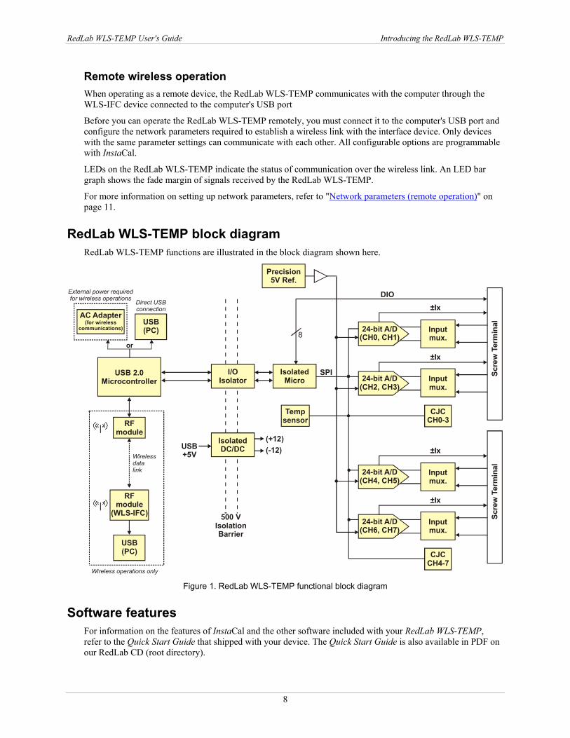
RedLab WLS-TEMP block diagram RedLab WLS-TEMP functions are illustrated in the block diagram shown here.
24-bit A/D(CH0, CH1)
Inputmux.
Inputmux.
CJCCH0-3
±Ix
Precision5V Ref.
24-bit A/D(CH2, CH3)
±Ix
24-bit A/D(CH4, CH5)
Inputmux.
Inputmux.
CJCCH4-7
±Ix
24-bit A/D(CH6, CH7)
±IxSc
rew
Ter
min
alSc
rew
Ter
min
al
IsolatedMicro
Tempsensor
I/OIsolator
500 VIsolationBarrier
SPI
IsolatedDC/DCUSB
+5V
(+12)(-12)
8
DIO
USB 2.0 Microcontroller
Direct USBconnection
USB(PC)
AC Adapter(for wireless
communications)
or
External power required for wireless operations
Wireless datalink
USB(PC)
RFmodule
RFmodule
(WLS-IFC)
Wireless operations only Figure 1. RedLab WLS-TEMP functional block diagram
Software features For information on the features of InstaCal and the other software included with your RedLab WLS-TEMP, refer to the Quick Start Guide that shipped with your device. The Quick Start Guide is also available in PDF on our RedLab CD (root directory).
9
Chapter 2
Installing the RedLab WLS-TEMP
What comes with your RedLab WLS-TEMP shipment? The following items are shipped with the RedLab WLS-TEMP.
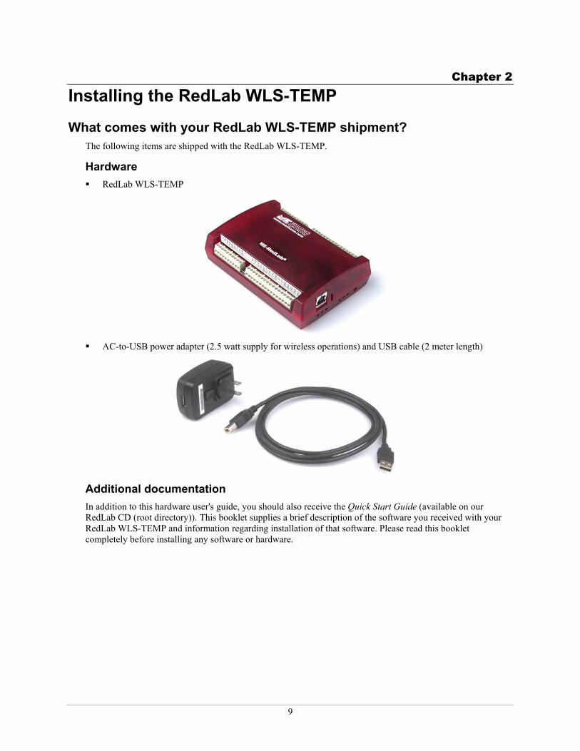
Hardware RedLab WLS-TEMP
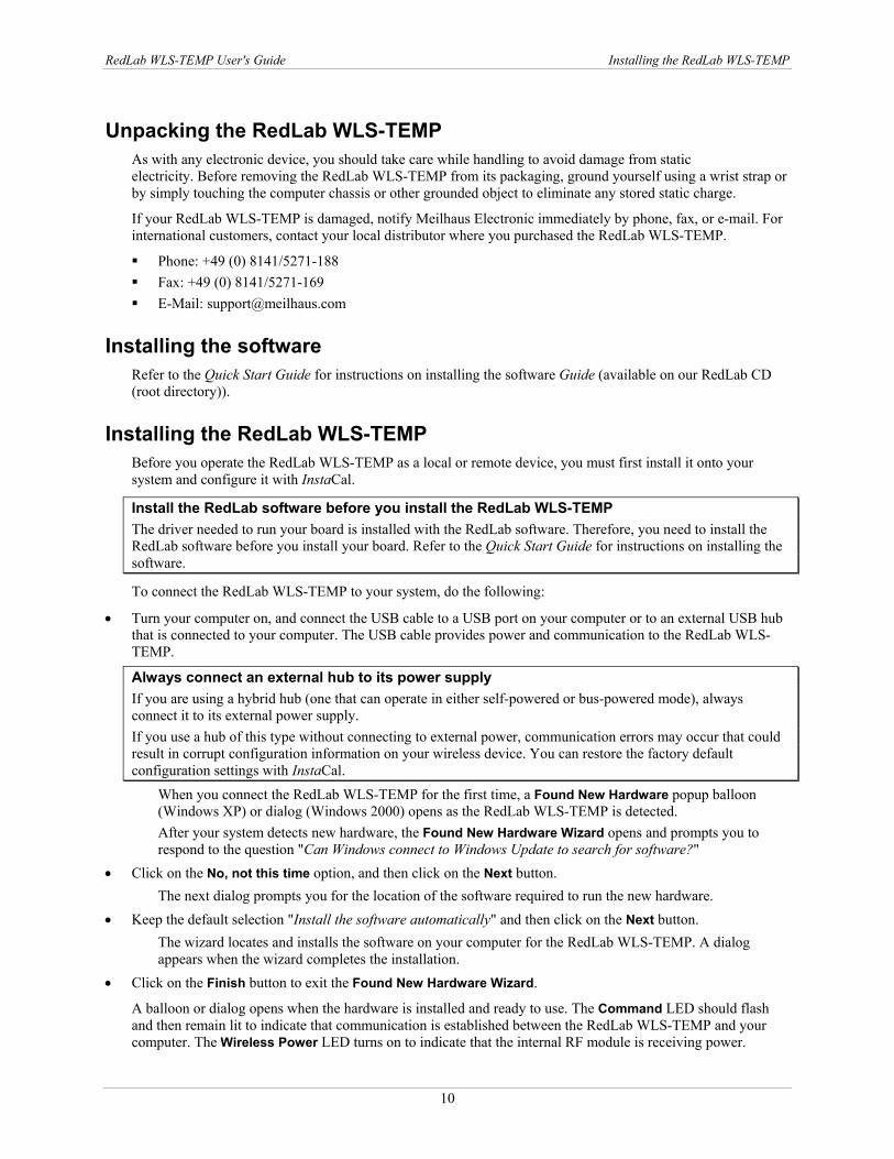
AC-to-USB power adapter (2.5 watt supply for wireless operations) and USB cable (2 meter length)
Additional documentation In addition to this hardware user's guide, you should also receive the Quick Start Guide (available on our RedLab CD (root directory)). This booklet supplies a brief description of the software you received with your RedLab WLS-TEMP and information regarding installation of that software. Please read this booklet completely before installing any software or hardware.
RedLab WLS-TEMP User's Guide Installing the RedLab WLS-TEMP
10
Unpacking the RedLab WLS-TEMP As with any electronic device, you should take care while handling to avoid damage from static electricity. Before removing the RedLab WLS-TEMP from its packaging, ground yourself using a wrist strap or by simply touching the computer chassis or other grounded object to eliminate any stored static charge.
If your RedLab WLS-TEMP is damaged, notify Meilhaus Electronic immediately by phone, fax, or e-mail. For international customers, contact your local distributor where you purchased the RedLab WLS-TEMP.
Phone: +49 (0) 8141/5271-188 Fax: +49 (0) 8141/5271-169 E-Mail: [email protected]
Installing the software Refer to the Quick Start Guide for instructions on installing the software Guide (available on our RedLab CD (root directory)).
Installing the RedLab WLS-TEMP Before you operate the RedLab WLS-TEMP as a local or remote device, you must first install it onto your system and configure it with InstaCal.
Install the RedLab software before you install the RedLab WLS-TEMP The driver needed to run your board is installed with the RedLab software. Therefore, you need to install the RedLab software before you install your board. Refer to the Quick Start Guide for instructions on installing the software.
To connect the RedLab WLS-TEMP to your system, do the following:
• Turn your computer on, and connect the USB cable to a USB port on your computer or to an external USB hub that is connected to your computer. The USB cable provides power and communication to the RedLab WLS-TEMP.
Always connect an external hub to its power supply If you are using a hybrid hub (one that can operate in either self-powered or bus-powered mode), always connect it to its external power supply. If you use a hub of this type without connecting to external power, communication errors may occur that could result in corrupt configuration information on your wireless device. You can restore the factory default configuration settings with InstaCal.
When you connect the RedLab WLS-TEMP for the first time, a Found New Hardware popup balloon (Windows XP) or dialog (Windows 2000) opens as the RedLab WLS-TEMP is detected. After your system detects new hardware, the Found New Hardware Wizard opens and prompts you to respond to the question "Can Windows connect to Windows Update to search for software?"
• Click on the No, not this time option, and then click on the Next button. The next dialog prompts you for the location of the software required to run the new hardware.
• Keep the default selection "Install the software automatically" and then click on the Next button. The wizard locates and installs the software on your computer for the RedLab WLS-TEMP. A dialog appears when the wizard completes the installation.
• Click on the Finish button to exit the Found New Hardware Wizard.
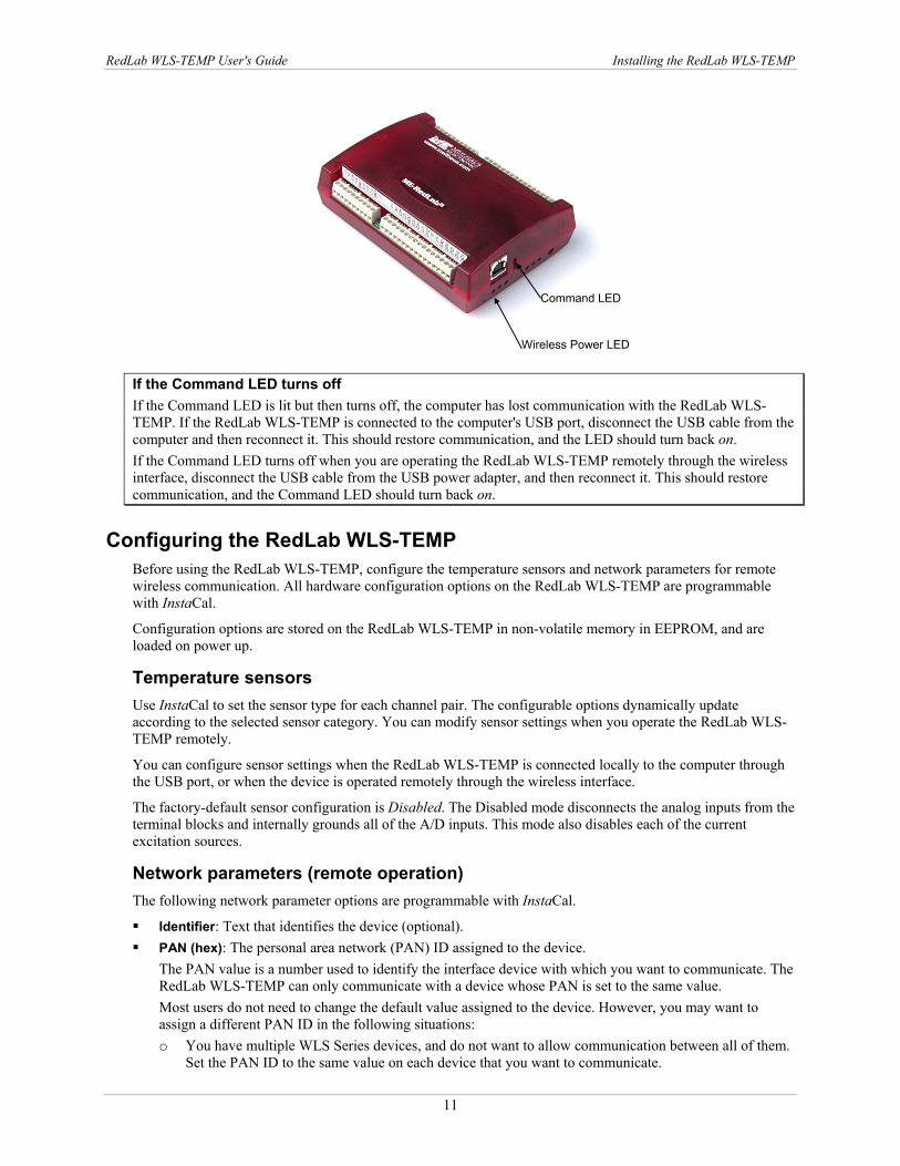
A balloon or dialog opens when the hardware is installed and ready to use. The Command LED should flash and then remain lit to indicate that communication is established between the RedLab WLS-TEMP and your computer. The Wireless Power LED turns on to indicate that the internal RF module is receiving power.
RedLab WLS-TEMP User's Guide Installing the RedLab WLS-TEMP
11
If the Command LED turns off If the Command LED is lit but then turns off, the computer has lost communication with the RedLab WLS-TEMP. If the RedLab WLS-TEMP is connected to the computer's USB port, disconnect the USB cable from the computer and then reconnect it. This should restore communication, and the LED should turn back on. If the Command LED turns off when you are operating the RedLab WLS-TEMP remotely through the wireless interface, disconnect the USB cable from the USB power adapter, and then reconnect it. This should restore communication, and the Command LED should turn back on.
Configuring the RedLab WLS-TEMP Before using the RedLab WLS-TEMP, configure the temperature sensors and network parameters for remote wireless communication. All hardware configuration options on the RedLab WLS-TEMP are programmable with InstaCal.
Configuration options are stored on the RedLab WLS-TEMP in non-volatile memory in EEPROM, and are loaded on power up.
Temperature sensors Use InstaCal to set the sensor type for each channel pair. The configurable options dynamically update according to the selected sensor category. You can modify sensor settings when you operate the RedLab WLS-TEMP remotely.
You can configure sensor settings when the RedLab WLS-TEMP is connected locally to the computer through the USB port, or when the device is operated remotely through the wireless interface.
The factory-default sensor configuration is Disabled. The Disabled mode disconnects the analog inputs from the terminal blocks and internally grounds all of the A/D inputs. This mode also disables each of the current excitation sources.
Network parameters (remote operation) The following network parameter options are programmable with InstaCal.
Identifier: Text that identifies the device (optional). PAN (hex): The personal area network (PAN) ID assigned to the device.
The PAN value is a number used to identify the interface device with which you want to communicate. The RedLab WLS-TEMP can only communicate with a device whose PAN is set to the same value. Most users do not need to change the default value assigned to the device. However, you may want to assign a different PAN ID in the following situations: o You have multiple WLS Series devices, and do not want to allow communication between all of them.
Set the PAN ID to the same value on each device that you want to communicate.
Command LED
Wireless Power LED
RedLab WLS-TEMP User's Guide Installing the RedLab WLS-TEMP
12
o If other WLS Series devices are operating in the vicinity, you can avoid accidental changes to your device settings by changing the default PAN value.
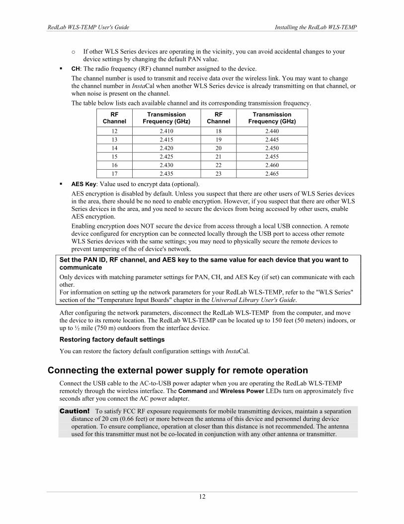
CH: The radio frequency (RF) channel number assigned to the device. The channel number is used to transmit and receive data over the wireless link. You may want to change the channel number in InstaCal when another WLS Series device is already transmitting on that channel, or when noise is present on the channel. The table below lists each available channel and its corresponding transmission frequency.
RF Channel
Transmission Frequency (GHz)
RF Channel
Transmission Frequency (GHz)
12 2.410 18 2.440 13 2.415 19 2.445 14 2.420 20 2.450 15 2.425 21 2.455 16 2.430 22 2.460 17 2.435 23 2.465
AES Key: Value used to encrypt data (optional). AES encryption is disabled by default. Unless you suspect that there are other users of WLS Series devices in the area, there should be no need to enable encryption. However, if you suspect that there are other WLS Series devices in the area, and you need to secure the devices from being accessed by other users, enable AES encryption. Enabling encryption does NOT secure the device from access through a local USB connection. A remote device configured for encryption can be connected locally through the USB port to access other remote WLS Series devices with the same settings; you may need to physically secure the remote devices to prevent tampering of the of device's network.
Set the PAN ID, RF channel, and AES key to the same value for each device that you want to communicate Only devices with matching parameter settings for PAN, CH, and AES Key (if set) can communicate with each other. For information on setting up the network parameters for your RedLab WLS-TEMP, refer to the "WLS Series" section of the "Temperature Input Boards" chapter in the Universal Library User's Guide.
After configuring the network parameters, disconnect the RedLab WLS-TEMP from the computer, and move the device to its remote location. The RedLab WLS-TEMP can be located up to 150 feet (50 meters) indoors, or up to ½ mile (750 m) outdoors from the interface device.
Restoring factory default settings
You can restore the factory default configuration settings with InstaCal.
Connecting the external power supply for remote operation Connect the USB cable to the AC-to-USB power adapter when you are operating the RedLab WLS-TEMP remotely through the wireless interface. The Command and Wireless Power LEDs turn on approximately five seconds after you connect the AC power adapter.
Caution! To satisfy FCC RF exposure requirements for mobile transmitting devices, maintain a separation distance of 20 cm (0.66 feet) or more between the antenna of this device and personnel during device operation. To ensure compliance, operation at closer than this distance is not recommended. The antenna used for this transmitter must not be co-located in conjunction with any other antenna or transmitter.
RedLab WLS-TEMP User's Guide Installing the RedLab WLS-TEMP
13
Calibrating the RedLab WLS-TEMP You can fully calibrate the RedLab WLS-TEMP using InstaCal. Allow a 30-minute warm up before calibrating. InstaCal prompts you to run its calibration utility if you change the sensor category. If you don't change the sensor category the normal calibration interval is once per year.
You can calibrate the RedLab WLS-TEMP when it is connected locally to the computer through the USB port, or when it is operated remotely through the wireless interface.
Warm up time Allow the RedLab WLS-TEMP to warm up for 30 minutes before taking measurements. This warm up time minimizes thermal drift and achieves the specified rated accuracy of measurements.
For RTD or thermistor measurements, this warm-up time is also required to stabilize the internal current reference.
14
Chapter 3
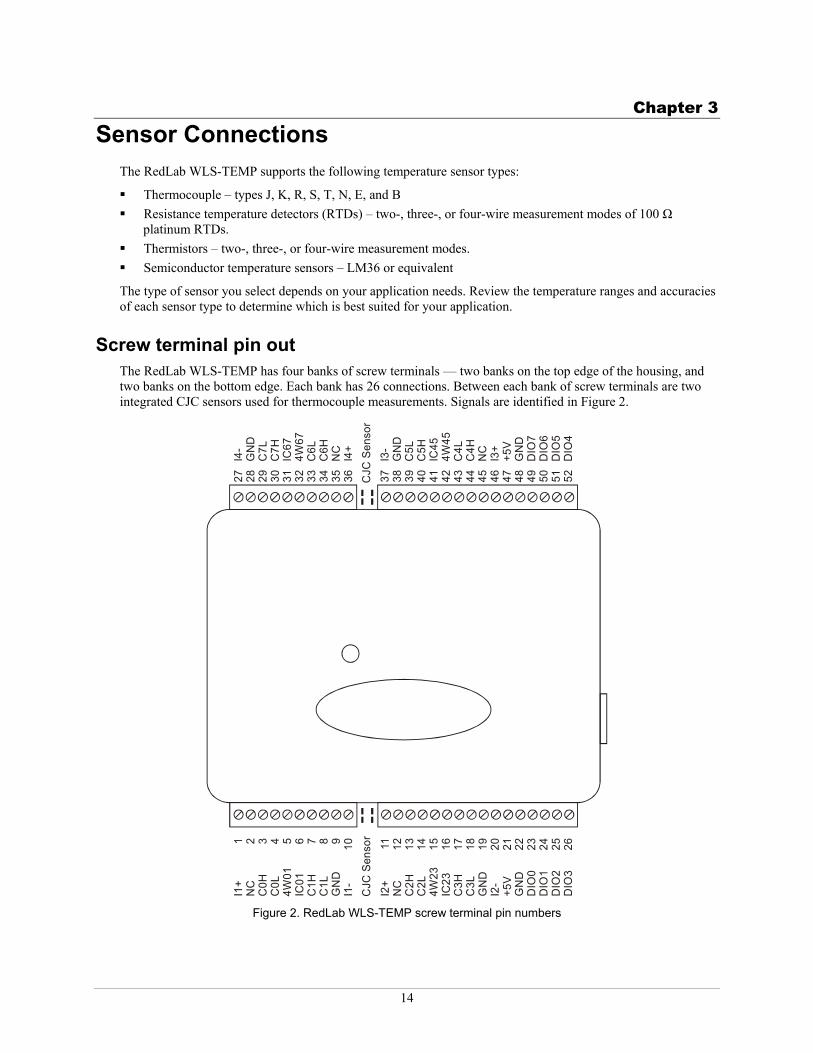
Sensor Connections The RedLab WLS-TEMP supports the following temperature sensor types:
Thermocouple – types J, K, R, S, T, N, E, and B Resistance temperature detectors (RTDs) – two-, three-, or four-wire measurement modes of 100 Ω
platinum RTDs. Thermistors – two-, three-, or four-wire measurement modes. Semiconductor temperature sensors – LM36 or equivalent
The type of sensor you select depends on your application needs. Review the temperature ranges and accuracies of each sensor type to determine which is best suited for your application.
Screw terminal pin out The RedLab WLS-TEMP has four banks of screw terminals — two banks on the top edge of the housing, and two banks on the bottom edge. Each bank has 26 connections. Between each bank of screw terminals are two integrated CJC sensors used for thermocouple measurements. Signals are identified in Figure 2.
I1+
1N
C2
C0H
3C
0L4
4W01
5IC
016
C1H
7C
1L8
GN
D9
I1-
10
I2+
11N
C12
C2H
13C
2L14
4W23
15IC
2316
C3H
17C
3L18
GN
D19
I2-
20+5
V21
GN
D22
DIO
023
DIO
124
DIO
225
DIO
326
27I4
-28
GN
D29
C7L
30C
7H31
IC67
324W
6733
C6L
34C
6H35
NC
36I4
+
37I3
-38
GN
D39
C5L
40C
5H41
IC45
424W
4543
C4L
44C
4H45
NC
46I3
+47
+5V
48G
ND
49D
IO7
50D
IO6
51D
IO5
52D
IO4
CJC
Sen
sor
CJC
Sen
sor
Figure 2. RedLab WLS-TEMP screw terminal pin numbers
RedLab WLS-TEMP User's Guide Sensor Connections
15
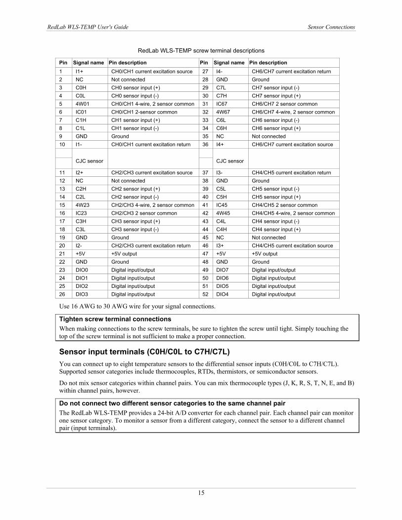
RedLab WLS-TEMP screw terminal descriptions
Pin Signal name Pin description Pin Signal name Pin description 1 I1+ CH0/CH1 current excitation source 27 I4- CH6/CH7 current excitation return 2 NC Not connected 28 GND Ground 3 C0H CH0 sensor input (+) 29 C7L CH7 sensor input (-) 4 C0L CH0 sensor input (-) 30 C7H CH7 sensor input (+) 5 4W01 CH0/CH1 4-wire, 2 sensor common 31 IC67 CH6/CH7 2 sensor common 6 IC01 CH0/CH1 2-sensor common 32 4W67 CH6/CH7 4-wire, 2 sensor common 7 C1H CH1 sensor input (+) 33 C6L CH6 sensor input (-) 8 C1L CH1 sensor input (-) 34 C6H CH6 sensor input (+) 9 GND Ground 35 NC Not connected 10 I1- CH0/CH1 current excitation return 36 I4+ CH6/CH7 current excitation source
CJC sensor
CJC sensor
11 I2+ CH2/CH3 current excitation source 37 I3- CH4/CH5 current excitation return 12 NC Not connected 38 GND Ground 13 C2H CH2 sensor input (+) 39 C5L CH5 sensor input (-) 14 C2L CH2 sensor input (-) 40 C5H CH5 sensor input (+) 15 4W23 CH2/CH3 4-wire, 2 sensor common 41 IC45 CH4/CH5 2 sensor common 16 IC23 CH2/CH3 2 sensor common 42 4W45 CH4/CH5 4-wire, 2 sensor common 17 C3H CH3 sensor input (+) 43 C4L CH4 sensor input (-) 18 C3L CH3 sensor input (-) 44 C4H CH4 sensor input (+) 19 GND Ground 45 NC Not connected 20 I2- CH2/CH3 current excitation return 46 I3+ CH4/CH5 current excitation source 21 +5V +5V output 47 +5V +5V output 22 GND Ground 48 GND Ground 23 DIO0 Digital input/output 49 DIO7 Digital input/output 24 DIO1 Digital input/output 50 DIO6 Digital input/output 25 DIO2 Digital input/output 51 DIO5 Digital input/output 26 DIO3 Digital input/output 52 DIO4 Digital input/output
Use 16 AWG to 30 AWG wire for your signal connections.
Tighten screw terminal connections When making connections to the screw terminals, be sure to tighten the screw until tight. Simply touching the top of the screw terminal is not sufficient to make a proper connection.
Sensor input terminals (C0H/C0L to C7H/C7L) You can connect up to eight temperature sensors to the differential sensor inputs (C0H/C0L to C7H/C7L). Supported sensor categories include thermocouples, RTDs, thermistors, or semiconductor sensors.
Do not mix sensor categories within channel pairs. You can mix thermocouple types (J, K, R, S, T, N, E, and B) within channel pairs, however.
Do not connect two different sensor categories to the same channel pair The RedLab WLS-TEMP provides a 24-bit A/D converter for each channel pair. Each channel pair can monitor one sensor category. To monitor a sensor from a different category, connect the sensor to a different channel pair (input terminals).
RedLab WLS-TEMP User's Guide Sensor Connections
16
Current excitation output terminals (±I1 to ±I4) The RedLab WLS-TEMP has four dedicated pairs of current excitation output terminals (±I1 to ±I4). These terminals have a built-in precision current source to provide excitation for the resistive sensors used for RTD and thermistor measurements.
Each current excitation terminal is dedicated to one pair of sensor input channels:
I1+ is the current excitation source for channel 0 and channel 1 I2+ is the current excitation source for channel 2 and channel 3 I3+ is the current excitation source for channel 4 and channel 5 I4+ is the current excitation source for channel 6 and channel 7
Four-wire, two sensor common terminals (4W01 to 4W67) These terminals are used as the common connection for four-wire configurations with two RTD or thermistor sensors.
Two sensor common terminals (IC01 to IC67) These terminals are used as the common connection for two-wire configurations with two RTD or thermistor sensors.
Ground terminals (GND) The six ground terminals (GND) provide a common ground for the input channels and DIO bits and are isolated (500 VDC) from the USB GND.
Power terminals (+5V) The two +5V output terminals are isolated (500 VDC) from the USB +5V.
Digital terminals (DIO0 to DIO7) You can connect up to eight digital I/O lines to the screw terminals labeled DIO0 to DIO7. Each terminal is software-configurable for input or output.
CJC sensors The RedLab WLS-TEMP has two built-in high-resolution temperature sensors. One sensor is located on the right side of the package, and one sensor is located at the left side.
Thermocouple connections A thermocouple consists of two dissimilar metals that are joined together at one end. When the junction of the metals is heated or cooled, a voltage is produced that correlates to temperature.
The RedLab WLS-TEMP makes fully-differential thermocouple measurements without the need of ground-referencing resistors. A 32-bit floating point value in either a voltage or temperature format is returned by software. An open thermocouple detection feature is available for each analog input which automatically detects an open or broken thermocouple.
Use InstaCal to select the thermocouple type (J, K, R, S, T, N, E, and B) and one or more sensor input channels to connect the thermocouple.
Wiring configuration Connect the thermocouple to the RedLab WLS-TEMP using a differential configuration, as shown in
RedLab WLS-TEMP User's Guide Sensor Connections
17
I#+
NC
C#H
C#L
4W##
IC##
C#H
C#L
GN
DI#
-
Figure 3.
I#+
NC
C#H
C#L
4W##
IC##
C#H
C#L
GN
DI#
-
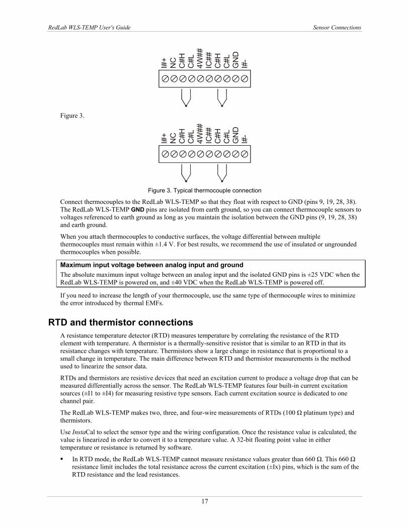
Figure 3. Typical thermocouple connection
Connect thermocouples to the RedLab WLS-TEMP so that they float with respect to GND (pins 9, 19, 28, 38). The RedLab WLS-TEMP GND pins are isolated from earth ground, so you can connect thermocouple sensors to voltages referenced to earth ground as long as you maintain the isolation between the GND pins (9, 19, 28, 38) and earth ground.
When you attach thermocouples to conductive surfaces, the voltage differential between multiple thermocouples must remain within ±1.4 V. For best results, we recommend the use of insulated or ungrounded thermocouples when possible.
Maximum input voltage between analog input and ground The absolute maximum input voltage between an analog input and the isolated GND pins is ±25 VDC when the RedLab WLS-TEMP is powered on, and ±40 VDC when the RedLab WLS-TEMP is powered off.
If you need to increase the length of your thermocouple, use the same type of thermocouple wires to minimize the error introduced by thermal EMFs.
RTD and thermistor connections A resistance temperature detector (RTD) measures temperature by correlating the resistance of the RTD element with temperature. A thermistor is a thermally-sensitive resistor that is similar to an RTD in that its resistance changes with temperature. Thermistors show a large change in resistance that is proportional to a small change in temperature. The main difference between RTD and thermistor measurements is the method used to linearize the sensor data.
RTDs and thermistors are resistive devices that need an excitation current to produce a voltage drop that can be measured differentially across the sensor. The RedLab WLS-TEMP features four built-in current excitation sources (±I1 to ±I4) for measuring resistive type sensors. Each current excitation source is dedicated to one channel pair.
The RedLab WLS-TEMP makes two, three, and four-wire measurements of RTDs (100 Ω platinum type) and thermistors.
Use InstaCal to select the sensor type and the wiring configuration. Once the resistance value is calculated, the value is linearized in order to convert it to a temperature value. A 32-bit floating point value in either temperature or resistance is returned by software.
In RTD mode, the RedLab WLS-TEMP cannot measure resistance values greater than 660 Ω. This 660 Ω resistance limit includes the total resistance across the current excitation (±Ix) pins, which is the sum of the RTD resistance and the lead resistances.
RedLab WLS-TEMP User's Guide Sensor Connections
18
In thermistor mode, the RedLab WLS-TEMP cannot measure resistance values greater than 180 kΩ. This 180 kΩ resistance limit includes the total resistance across the current excitation (±Ix) pins, which is the sum of the thermistor resistance and the lead resistance.
Two-wire configuration The easiest way to connect an RTD sensor or thermistor to the RedLab WLS-TEMP is with a two-wire configuration, since it requires the fewest connections to the sensor. With this method, the two wires that provide the RTD sensor with its excitation current also measure the voltage across the sensor.
Since RTDs exhibit a low nominal resistance, the lead wire resistance can affect measurement accuracy. For example, connecting lead wires that have a resistance of 1 Ω (0.5 Ω each lead) to a 100 Ω platinum RTD results in a 1% measurement error.
With a two-wire configuration, you can connect either one sensor per channel pair, or two sensors per channel pair.
Two-wire, single-sensor
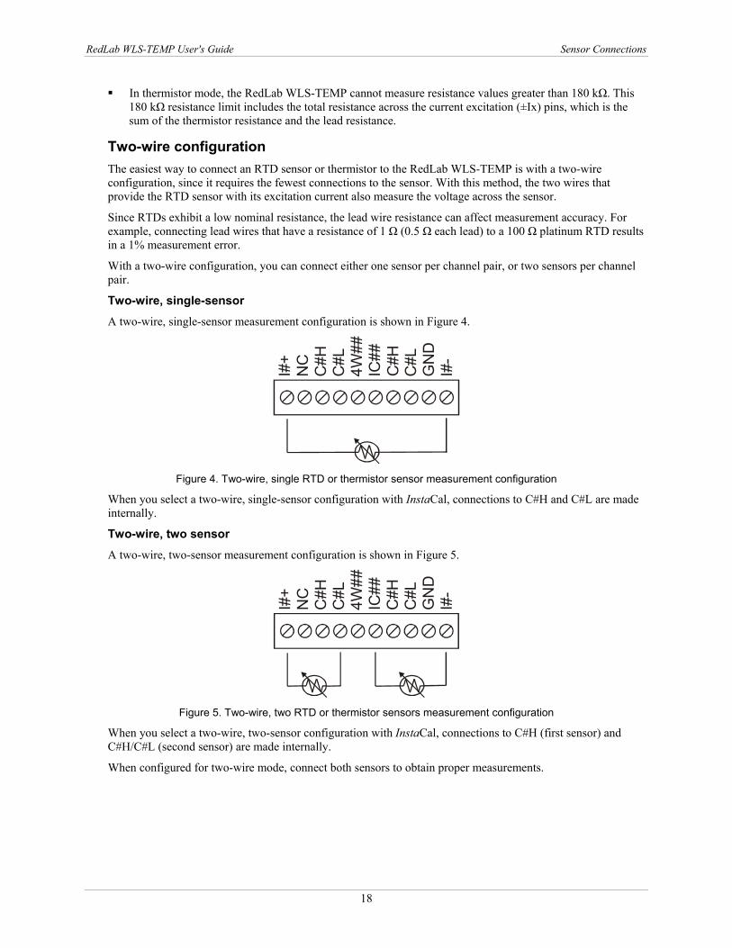
A two-wire, single-sensor measurement configuration is shown in Figure 4.
I#+
NC
C#H
C#L
4W##
IC##
C#H
C#L
GN
DI#
-
Figure 4. Two-wire, single RTD or thermistor sensor measurement configuration
When you select a two-wire, single-sensor configuration with InstaCal, connections to C#H and C#L are made internally.
Two-wire, two sensor
A two-wire, two-sensor measurement configuration is shown in Figure 5.
I#+
NC
C#H
C#L
4W##
IC##
C#H
C#L
GN
DI#
-
Figure 5. Two-wire, two RTD or thermistor sensors measurement configuration
When you select a two-wire, two-sensor configuration with InstaCal, connections to C#H (first sensor) and C#H/C#L (second sensor) are made internally.
When configured for two-wire mode, connect both sensors to obtain proper measurements.
RedLab WLS-TEMP User's Guide Sensor Connections
19
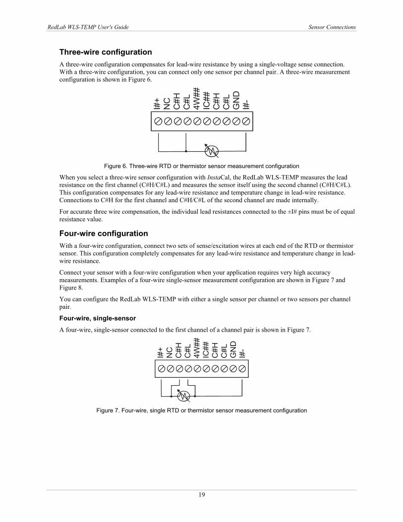
Three-wire configuration A three-wire configuration compensates for lead-wire resistance by using a single-voltage sense connection. With a three-wire configuration, you can connect only one sensor per channel pair. A three-wire measurement configuration is shown in Figure 6.
I#+
NC
C#H
C#L
4W##
IC##
C#H
C#L
GN
DI#
-
Figure 6. Three-wire RTD or thermistor sensor measurement configuration
When you select a three-wire sensor configuration with InstaCal, the RedLab WLS-TEMP measures the lead resistance on the first channel (C#H/C#L) and measures the sensor itself using the second channel (C#H/C#L). This configuration compensates for any lead-wire resistance and temperature change in lead-wire resistance. Connections to C#H for the first channel and C#H/C#L of the second channel are made internally.
For accurate three wire compensation, the individual lead resistances connected to the ±I# pins must be of equal resistance value.
Four-wire configuration With a four-wire configuration, connect two sets of sense/excitation wires at each end of the RTD or thermistor sensor. This configuration completely compensates for any lead-wire resistance and temperature change in lead-wire resistance.
Connect your sensor with a four-wire configuration when your application requires very high accuracy measurements. Examples of a four-wire single-sensor measurement configuration are shown in Figure 7 and Figure 8.
You can configure the RedLab WLS-TEMP with either a single sensor per channel or two sensors per channel pair.
Four-wire, single-sensor A four-wire, single-sensor connected to the first channel of a channel pair is shown in Figure 7.
I#+
NC
C#H
C#L
4W##
IC##
C#H
C#L
GN
DI#
-
Figure 7. Four-wire, single RTD or thermistor sensor measurement configuration
RedLab WLS-TEMP User's Guide Sensor Connections
20
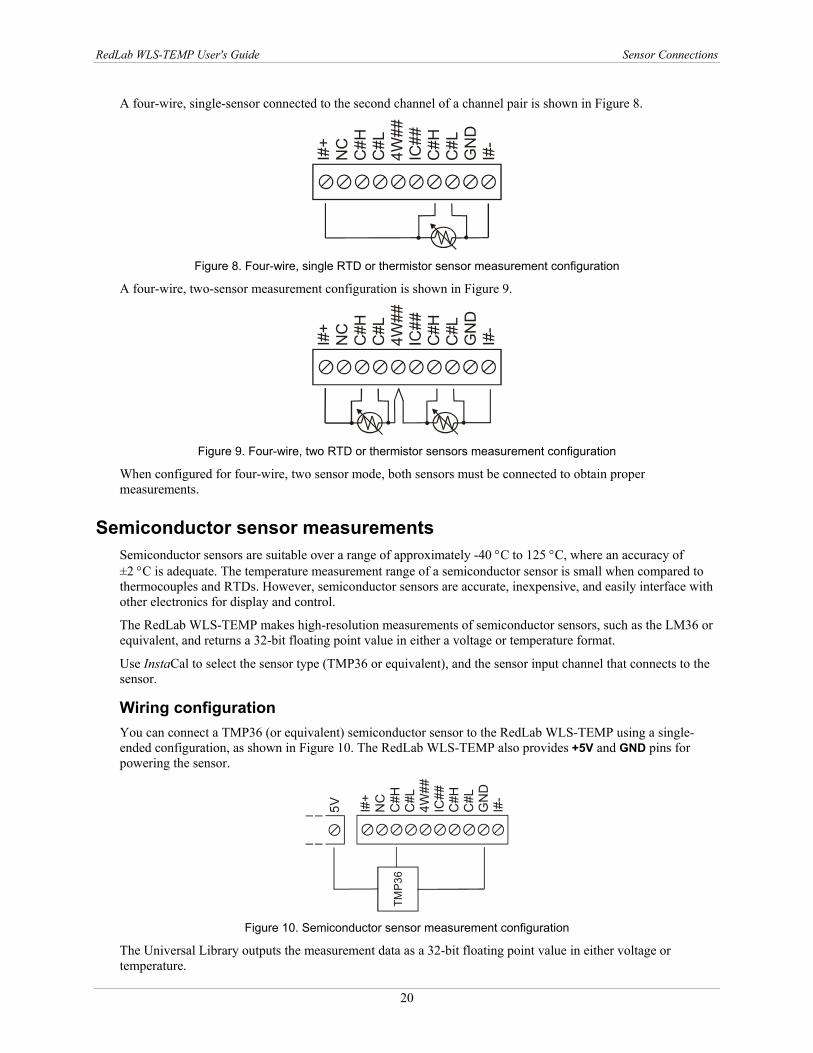
A four-wire, single-sensor connected to the second channel of a channel pair is shown in Figure 8.
I#+
NC
C#H
C#L
4W##
IC##
C#H
C#L
GN
DI#
-
Figure 8. Four-wire, single RTD or thermistor sensor measurement configuration
A four-wire, two-sensor measurement configuration is shown in Figure 9.
I#+
NC
C#H
C#L
4W##
C#H
C#L
GN
DI#
-
Figure 9. Four-wire, two RTD or thermistor sensors measurement configuration
When configured for four-wire, two sensor mode, both sensors must be connected to obtain proper measurements.
Semiconductor sensor measurements Semiconductor sensors are suitable over a range of approximately -40 °C to 125 °C, where an accuracy of ±2 °C is adequate. The temperature measurement range of a semiconductor sensor is small when compared to thermocouples and RTDs. However, semiconductor sensors are accurate, inexpensive, and easily interface with other electronics for display and control.
The RedLab WLS-TEMP makes high-resolution measurements of semiconductor sensors, such as the LM36 or equivalent, and returns a 32-bit floating point value in either a voltage or temperature format.
Use InstaCal to select the sensor type (TMP36 or equivalent), and the sensor input channel that connects to the sensor.
Wiring configuration You can connect a TMP36 (or equivalent) semiconductor sensor to the RedLab WLS-TEMP using a single-ended configuration, as shown in Figure 10. The RedLab WLS-TEMP also provides +5V and GND pins for powering the sensor.
I#+
NC
C#H
C#L
4W##
IC##
C#H
C#L
GN
DI#
-
TMP3
6
5V
Figure 10. Semiconductor sensor measurement configuration
The Universal Library outputs the measurement data as a 32-bit floating point value in either voltage or temperature.
RedLab WLS-TEMP User's Guide Sensor Connections
21
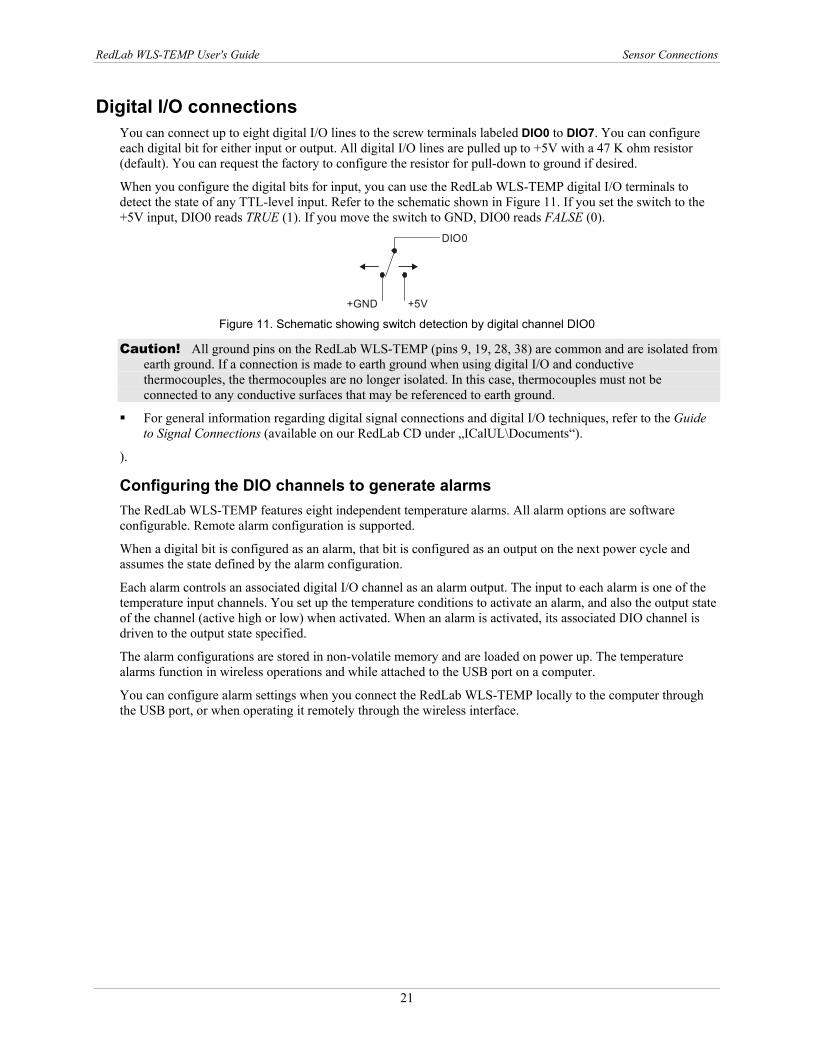
Digital I/O connections You can connect up to eight digital I/O lines to the screw terminals labeled DIO0 to DIO7. You can configure each digital bit for either input or output. All digital I/O lines are pulled up to +5V with a 47 K ohm resistor (default). You can request the factory to configure the resistor for pull-down to ground if desired.
When you configure the digital bits for input, you can use the RedLab WLS-TEMP digital I/O terminals to detect the state of any TTL-level input. Refer to the schematic shown in Figure 11. If you set the switch to the +5V input, DIO0 reads TRUE (1). If you move the switch to GND, DIO0 reads FALSE (0).
+5V+GND
DIO0
Figure 11. Schematic showing switch detection by digital channel DIO0
Caution! All ground pins on the RedLab WLS-TEMP (pins 9, 19, 28, 38) are common and are isolated from earth ground. If a connection is made to earth ground when using digital I/O and conductive thermocouples, the thermocouples are no longer isolated. In this case, thermocouples must not be connected to any conductive surfaces that may be referenced to earth ground.
For general information regarding digital signal connections and digital I/O techniques, refer to the Guide to Signal Connections (available on our RedLab CD under „ICalUL\Documents“).
).
Configuring the DIO channels to generate alarms The RedLab WLS-TEMP features eight independent temperature alarms. All alarm options are software configurable. Remote alarm configuration is supported.
When a digital bit is configured as an alarm, that bit is configured as an output on the next power cycle and assumes the state defined by the alarm configuration.
Each alarm controls an associated digital I/O channel as an alarm output. The input to each alarm is one of the temperature input channels. You set up the temperature conditions to activate an alarm, and also the output state of the channel (active high or low) when activated. When an alarm is activated, its associated DIO channel is driven to the output state specified.
The alarm configurations are stored in non-volatile memory and are loaded on power up. The temperature alarms function in wireless operations and while attached to the USB port on a computer.
You can configure alarm settings when you connect the RedLab WLS-TEMP locally to the computer through the USB port, or when operating it remotely through the wireless interface.
22
Chapter 4
Functional Details
Thermocouple measurements A thermocouple consists of two dissimilar metals that are joined together at one end. When the junction of the metals is heated or cooled, a voltage is produced that correlates to temperature.
The RedLab WLS-TEMP hardware level-shifts the thermocouple’s output voltage into the A/D’s common mode input range by applying +2.5 V to the thermocouple’s low side at the C#L input. Always connect thermocouple sensors to the RedLab WLS-TEMP in a floating fashion. Do not attempt to connect the thermocouple low side C#L to GND or to a ground referencing resistor.
Cold junction compensation (CJC) When you connect the thermocouple sensor leads to the sensor input channel, the dissimilar metals at the RedLab WLS-TEMP terminal blocks produce an additional thermocouple junction. This junction creates a small voltage error term which must be removed from the overall sensor measurement using a cold junction compensation technique. The measured voltage includes both the thermocouple voltage and the cold junction voltage. To compensate for the additional cold junction voltage, the RedLab WLS-TEMP subtracts the cold junction voltage from the thermocouple voltage.
The RedLab WLS-TEMP has two high-resolution temperature sensors that are integrated into the design of the RedLab WLS-TEMP. One sensor is located on the right side of the package, and one sensor is located at the left side. The CJC sensors measure the average temperature at the terminal blocks so that the cold junction voltage can be calculated. A software algorithm automatically corrects for the additional thermocouples created at the terminal blocks by subtracting the calculated cold junction voltage from the analog input's thermocouple voltage measurement.
Increasing the thermocouple length If you need to increase the length of your thermocouple, use the same type of thermocouple wires to minimize the error introduced by thermal EMFs.
Data linearization After the CJC correction is performed on the measurement data, an onboard microcontroller automatically linearizes the thermocouple measurement data using National Institute of Standards and Technology (NIST) linearization coefficients for the selected thermocouple type.
The measurement data is then output as a 32-bit floating point value in the configured format (voltage or temperature).
Open-thermocouple detection (OTD) Open-thermocouple detection (OTD) is automatically enabled for each analog input channel when a channel pair is configured for thermocouple sensor. The maximum open detection time is 3 seconds.
With OTD, any open-circuit or short-circuit condition at the thermocouple sensor is detected by the software. An open channel is detected by driving the input voltage to a negative value outside the range of any thermocouple output. The software recognizes this as an invalid reading and flags the appropriate channel. The software continues to sample all channels when OTD is detected.
Input leakage current With open-thermocouple detection enabled, a maximum of 105 nA of input leakage current is injected into the thermocouple. This current can cause an error voltage to develop across the lead resistance of the thermocouple that is indistinguishable from the thermocouple voltage you are measuring. You can estimate this error voltage with the following formula:
error voltage = resistance of the thermocouple x 105 nA
RedLab WLS-TEMP User's Guide Functional Details
23
To reduce the error, reduce the length of the thermocouple to lower its resistance, or lower the AWG of the wire by using a wire with a larger diameter. With OTD disabled, a maximum of 30 nA of input leakage current is injected into the thermocouple.
RTD and thermistor measurements RTDs and thermistors are resistive devices that require an excitation current to produce a voltage drop that can be measured differentially across the sensor. The RedLab WLS-TEMP measures the sensor resistance by forcing a known excitation current through the sensor and then measuring (differentially) the voltage across the sensor to determine its resistance.
After the voltage measurement is made, the resistance of the RTD is calculated using Ohms law – the sensor resistance is calculated by dividing the measured voltage by the current excitation level (±Ix) source. The value of the ±Ix source is stored in local memory.
Once the resistance value is calculated, the value is linearized in order to convert it to a temperature value. The measurement is returned by software as a 32-bit floating point value in a voltage, resistance or temperature format.
Data linearization An onboard microcontroller automatically performs linearization on RTD and thermistor measurements.
RTD measurements are linearized using a Callendar-Van Dusen coefficients algorithm (you select DIN, SAMA, or ITS-90).
Thermistor measurements are linearized using a Steinhart-Hart linearization algorithm (you supply the coefficients from the sensor manufacturer's data sheet).
AC power supply The external power supply is an AC-to-USB 2.5 W supply that is used to power the RedLab WLS-TEMP during remote wireless operations .
RedLab WLS-TEMP User's Guide Functional Details
24
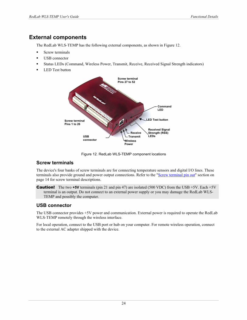
External components The RedLab WLS-TEMP has the following external components, as shown in Figure 12.
Screw terminals USB connector Status LEDs (Command, Wireless Power, Transmit, Receive, Received Signal Strength indicators) LED Test button
Figure 12. RedLab WLS-TEMP component locations
Screw terminals The device's four banks of screw terminals are for connecting temperature sensors and digital I/O lines. These terminals also provide ground and power output connections. Refer to the "Screw terminal pin out" section on page 14 for screw terminal descriptions.
Caution! The two +5V terminals (pin 21 and pin 47) are isolated (500 VDC) from the USB +5V. Each +5V terminal is an output. Do not connect to an external power supply or you may damage the RedLab WLS-TEMP and possibly the computer.
USB connector The USB connector provides +5V power and communication. External power is required to operate the RedLab WLS-TEMP remotely through the wireless interface.
For local operation, connect to the USB port or hub on your computer. For remote wireless operation, connect to the external AC adapter shipped with the device.
USB connector
Screw terminal Pins 1 to 26
CommandLED
Received Signal Strength (RSS) LEDs
LED Test button
Wireless Power
TransmitReceive
Screw terminalPins 27 to 52
RedLab WLS-TEMP User's Guide Functional Details
25
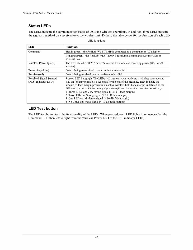
Status LEDs The LEDs indicate the communication status of USB and wireless operations. In addition, three LEDs indicate the signal strength of data received over the wireless link. Refer to the table below for the function of each LED.
LED functions
LED Function Steady green – the RedLab WLS-TEMP is connected to a computer or AC adapter Command Blinking green – the RedLab WLS-TEMP is receiving a command over the USB or wireless link.
Wireless Power (green) The RedLab WLS-TEMP device's internal RF module is receiving power (USB or AC adapter).
Transmit (yellow) Data is being transmitted over an active wireless link. Receive (red) Data is being received over an active wireless link. Received Signal Strength (RSS) Indicator LEDs
3 green LED bar graph. The LEDs will turn on when receiving a wireless message and stay on for approximately 1 second after the end of the message. They indicate the amount of fade margin present in an active wireless link. Fade margin is defined as the difference between the incoming signal strength and the device’s receiver sensitivity. 1 Three LEDs on: Very strong signal (> 30 dB fade margin) 2 Two LEDs on: Strong signal (> 20 dB fade margin) 3 One LED on: Moderate signal (> 10 dB fade margin) 4 No LEDs on: Weak signal (< 10 dB fade margin)
LED Test button The LED test button tests the functionality of the LEDs. When pressed, each LED lights in sequence (first the Command LED then left to right from the Wireless Power LED to the RSS indicator LEDs).
26
Chapter 5
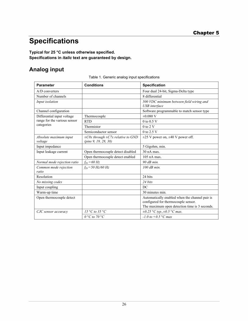
Specifications Typical for 25 °C unless otherwise specified. Specifications in italic text are guaranteed by design.
Analog input Table 1. Generic analog input specifications
Parameter Conditions Specification A/D converters Four dual 24-bit, Sigma-Delta type Number of channels 8 differential Input isolation 500 VDC minimum between field wiring and
USB interface Channel configuration Software programmable to match sensor type
Thermocouple ±0.080 V RTD 0 to 0.5 V Thermistor 0 to 2 V
Differential input voltage range for the various sensor categories
Semiconductor sensor 0 to 2.5 V Absolute maximum input voltage
±C0x through ±C7x relative to GND (pins 9, 19, 28, 38)
±25 V power on, ±40 V power off.
Input impedance 5 Gigohm, min. Open thermocouple detect disabled 30 nA max. Input leakage current Open thermocouple detect enabled 105 nA max.
Normal mode rejection ratio fIN =60 Hz 90 dB min. Common mode rejection ratio
fIN =50 Hz/60 Hz 100 dB min.
Resolution 24 bits No missing codes 24 bits Input coupling DC Warm-up time 30 minutes min. Open thermocouple detect Automatically enabled when the channel pair is
configured for thermocouple sensor. The maximum open detection time is 3 seconds.
15 °C to 35 °C ±0.25 °C typ.,±0.5 °C max. CJC sensor accuracy 0 °C to 70 °C -1.0 to +0.5 °C max
RedLab WLS-TEMP User's Guide Specifications
27
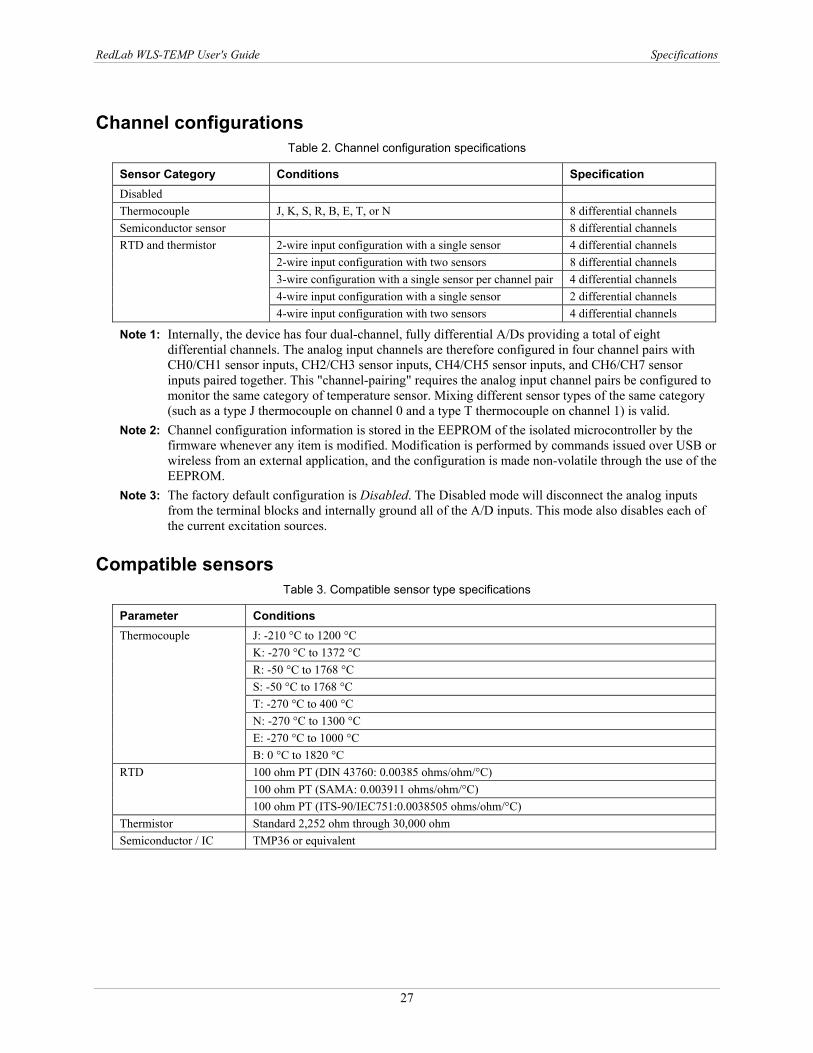
Channel configurations Table 2. Channel configuration specifications
Sensor Category Conditions Specification Disabled Thermocouple J, K, S, R, B, E, T, or N 8 differential channels Semiconductor sensor 8 differential channels
2-wire input configuration with a single sensor 4 differential channels 2-wire input configuration with two sensors 8 differential channels 3-wire configuration with a single sensor per channel pair 4 differential channels 4-wire input configuration with a single sensor 2 differential channels
RTD and thermistor
4-wire input configuration with two sensors 4 differential channels
Note 1: Internally, the device has four dual-channel, fully differential A/Ds providing a total of eight differential channels. The analog input channels are therefore configured in four channel pairs with CH0/CH1 sensor inputs, CH2/CH3 sensor inputs, CH4/CH5 sensor inputs, and CH6/CH7 sensor inputs paired together. This "channel-pairing" requires the analog input channel pairs be configured to monitor the same category of temperature sensor. Mixing different sensor types of the same category (such as a type J thermocouple on channel 0 and a type T thermocouple on channel 1) is valid.
Note 2: Channel configuration information is stored in the EEPROM of the isolated microcontroller by the firmware whenever any item is modified. Modification is performed by commands issued over USB or wireless from an external application, and the configuration is made non-volatile through the use of the EEPROM.
Note 3: The factory default configuration is Disabled. The Disabled mode will disconnect the analog inputs from the terminal blocks and internally ground all of the A/D inputs. This mode also disables each of the current excitation sources.
Compatible sensors Table 3. Compatible sensor type specifications
Parameter Conditions J: -210 °C to 1200 °C K: -270 °C to 1372 °C R: -50 °C to 1768 °C S: -50 °C to 1768 °C T: -270 °C to 400 °C N: -270 °C to 1300 °C E: -270 °C to 1000 °C
Thermocouple
B: 0 °C to 1820 °C 100 ohm PT (DIN 43760: 0.00385 ohms/ohm/°C) 100 ohm PT (SAMA: 0.003911 ohms/ohm/°C)
RTD
100 ohm PT (ITS-90/IEC751:0.0038505 ohms/ohm/°C) Thermistor Standard 2,252 ohm through 30,000 ohm Semiconductor / IC TMP36 or equivalent
RedLab WLS-TEMP User's Guide Specifications
28
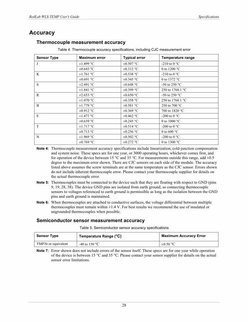
Accuracy Thermocouple measurement accuracy
Table 4. Thermocouple accuracy specifications, including CJC measurement error
Sensor Type Maximum error Typical error Temperature range ±1.499 °C ±0.507 °C -210 to 0 °C J ±0.643 °C ±0.312 °C 0 to 1200 °C ±1.761 °C ±0.538 °C -210 to 0 °C K ±0.691 °C ±0.345 °C 0 to 1372 °C ±2.491 °C ±0.648 °C -50 to 250 °C S ±1.841 °C ±0.399 °C 250 to 1768.1 °C ±2.653 °C ±0.650 °C -50 to 250 °C R ±1.070 °C ±0.358 °C 250 to 1768.1 °C ±1.779 °C ±0.581 °C 250 to 700 °C B ±0.912 °C ±0.369 °C 700 to 1820 °C ±1.471 °C ±0.462 °C -200 to 0 °C E ±0.639 °C ±0.245 °C 0 to 1000 °C ±1.717 °C ±0.514 °C -200 to 0 °C T ±0.713 °C ±0.256 °C 0 to 600 °C ±1.969 °C ±0.502 °C -200 to 0 °C N ±0.769 °C ±0.272 °C 0 to 1300 °C
Note 4: Thermocouple measurement accuracy specifications include linearization, cold-junction compensation and system noise. These specs are for one year, or 3000 operating hours, whichever comes first, and for operation of the device between 15 °C and 35 °C. For measurements outside this range, add ±0.5 degree to the maximum error shown. There are CJC sensors on each side of the module. The accuracy listed above assumes the screw terminals are at the same temperature as the CJC sensor. Errors shown do not include inherent thermocouple error. Please contact your thermocouple supplier for details on the actual thermocouple error.
Note 5: Thermocouples must be connected to the device such that they are floating with respect to GND (pins 9, 19, 28, 38). The device GND pins are isolated from earth ground, so connecting thermocouple sensors to voltages referenced to earth ground is permissible as long as the isolation between the GND pins and earth ground is maintained.
Note 6: When thermocouples are attached to conductive surfaces, the voltage differential between multiple thermocouples must remain within ±1.4 V. For best results we recommend the use of insulated or ungrounded thermocouples when possible.
Semiconductor sensor measurement accuracy Table 5. Semiconductor sensor accuracy specifications
Sensor Type Temperature Range (°C) Maximum Accuracy Error
TMP36 or equivalent -40 to 150 °C ±0.50 °C
Note 7: Error shown does not include errors of the sensor itself. These specs are for one year while operation of the device is between 15 °C and 35 °C. Please contact your sensor supplier for details on the actual sensor error limitations.
RedLab WLS-TEMP User's Guide Specifications
29
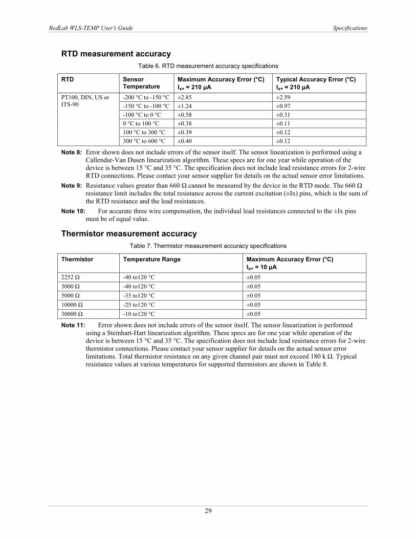
RTD measurement accuracy Table 6. RTD measurement accuracy specifications
RTD Sensor Temperature
Maximum Accuracy Error (°C) Ix+ = 210 µA
Typical Accuracy Error (°C) Ix+ = 210 µA
-200 °C to -150 °C ±2.85 ±2.59 -150 °C to -100 °C ±1.24 ±0.97 -100 °C to 0 °C ±0.58 ±0.31 0 °C to 100 °C ±0.38 ±0.11 100 °C to 300 °C ±0.39 ±0.12
PT100, DIN, US or ITS-90
300 °C to 600 °C ±0.40 ±0.12
Note 8: Error shown does not include errors of the sensor itself. The sensor linearization is performed using a Callendar-Van Dusen linearization algorithm. These specs are for one year while operation of the device is between 15 °C and 35 °C. The specification does not include lead resistance errors for 2-wire RTD connections. Please contact your sensor supplier for details on the actual sensor error limitations.
Note 9: Resistance values greater than 660 Ω cannot be measured by the device in the RTD mode. The 660 Ω resistance limit includes the total resistance across the current excitation (±Ix) pins, which is the sum of the RTD resistance and the lead resistances.
Note 10: For accurate three wire compensation, the individual lead resistances connected to the ±Ix pins must be of equal value.
Thermistor measurement accuracy Table 7. Thermistor measurement accuracy specifications
Thermistor Temperature Range Maximum Accuracy Error (°C) Ix+ = 10 µA
2252 Ω -40 to120 °C ±0.05 3000 Ω -40 to120 °C ±0.05 5000 Ω -35 to120 °C ±0.05 10000 Ω -25 to120 °C ±0.05 30000 Ω -10 to120 °C ±0.05
Note 11: Error shown does not include errors of the sensor itself. The sensor linearization is performed using a Steinhart-Hart linearization algorithm. These specs are for one year while operation of the device is between 15 °C and 35 °C. The specification does not include lead resistance errors for 2-wire thermistor connections. Please contact your sensor supplier for details on the actual sensor error limitations. Total thermistor resistance on any given channel pair must not exceed 180 k Ω. Typical resistance values at various temperatures for supported thermistors are shown in Table 8.

RedLab WLS-TEMP User's Guide Specifications
30
Table 8. Typical thermistor resistance specifications
Temp 2252 Ω thermistor
3000 Ω thermistor
5 kΩ thermistor
10 kΩ thermistor
30 kΩ thermistor
-40 °C 76 kΩ 101 kΩ 168 kΩ 240 kΩ (Note 12) 885 kΩ (Note 12) -35 °C 55 kΩ 73 kΩ 121 kΩ 179 kΩ 649 kΩ (Note 12) -30 °C 40 kΩ 53 kΩ 88 kΩ 135 kΩ 481 kΩ (Note 12) -25 °C 29 kΩ 39 kΩ 65 kΩ 103 kΩ 360 kΩ (Note 12) -20 °C 22 kΩ 29 kΩ 49 kΩ 79 kΩ 271 kΩ (Note 12) -15 °C 16 kΩ 22 kΩ 36 kΩ 61 kΩ 206 kΩ (Note 12) -10 °C 12 kΩ 17 kΩ 28 kΩ 48 kΩ 158 kΩ -5 °C 9.5 kΩ 13 kΩ 21 kΩ 37 kΩ 122 kΩ 0 °C 7.4 kΩ 9.8 kΩ 16 kΩ 29 kΩ 95 kΩ
Note 12: Resistance values greater than 180 kΩ cannot be measured by the device in the thermistor mode. The 180 kΩ resistance limit includes the total resistance across the current excitation (±Ix) pins, which is the sum of the thermistor resistance and the lead resistances.
Note 13: For accurate three wire compensation, the individual lead resistances connected to the ±Ix pins must be of equal value.
Throughput rate to PC (USB or wireless) Table 9. Throughput rate specifications
Number of Input Channels Maximum Throughput 1 2 Samples/second 2 2 S/s on each channel, 4 S/s total 3 2 S/s on each channel, 6 S/s total 4 2 S/s on each channel, 8 S/s total 5 2 S/s on each channel, 10 S/s total 6 2 S/s on each channel, 12 S/s total 7 2 S/s on each channel, 14 S/s total 8 2 S/s on each channel, 16 S/s total
Note 14: The analog inputs are configured to run continuously. Each channel is sampled twice per second. The maximum latency between when a sample is acquired and the temperature data is provided by the device is approximately 0.5 seconds

RedLab WLS-TEMP User's Guide Specifications
31
Digital input/output Table 10. Digital input/output specifications
Digital type CMOS Number of I/O 8 (DIO0 through DIO7) Configuration Independently configured for input or output.
Power on reset is input mode unless bit is configured for alarm. Pull up/pull-down configuration
All pins pulled up to +5 V via 47 K kΩ resistors (default). Pull down to ground (GND) also available.
Digital I/O transfer rate (software paced)
5 Digital input – 50 port reads or single bit reads per second typ. 6 Digital output – 100 port writes or single bit writes per second typ.
Input high voltage 2.0 V min., 5.5 V absolute max. Input low voltage 0.8 V max., -0.5 V absolute min. Output low voltage (IOL = 2.5 mA)
0.7 V max
Output high voltage (IOH = -2.5 mA)
3.8 V min.
Note 15: All ground pins on the device (pins 9, 19, 28, 38) are common and are isolated from earth ground. If a connection is made to earth ground when using digital I/O and conductive thermocouples, the thermocouples are no longer isolated. In this case, thermocouples must not be connected to any conductive surfaces that may be referenced to earth ground.
Temperature alarms Table 11. Temperature alarm specifications
Number of alarms 8 (one per digital I/O line) Alarm functionality Each alarm controls its associated digital I/O line as an alarm output. The input to each
alarm may be any of the analog temperature input channels. When an alarm is enabled, its associated I/O line is set to output (after the device is reset) and driven to the appropriate state determined by the alarm options and input temperature. The alarm configurations are stored in non-volatile memory and are loaded at power on. Alarms will function both in wireless mode and while attached to USB.
Alarm input modes 7 Alarm when input temperature > T1 8 Alarm when input temperature > T1, reset alarm when input temperature goes below T2 9 Alarm when input temperature < T1 10Alarm when input temperature < T1, reset alarm when input temperature goes above T2 11Alarm when input temperature is < T1 or > T2 Note: T1 and T2 may be independently set for each alarm.
Alarm output modes 12Disabled, digital I/O line may be used for normal operation 13Enabled, active high output (digital I/O line goes high when alarm conditions met) 14Enabled, active low output (digital I/O line goes low when alarm conditions met)
Alarm update rate 1 second
RedLab WLS-TEMP User's Guide Specifications
32
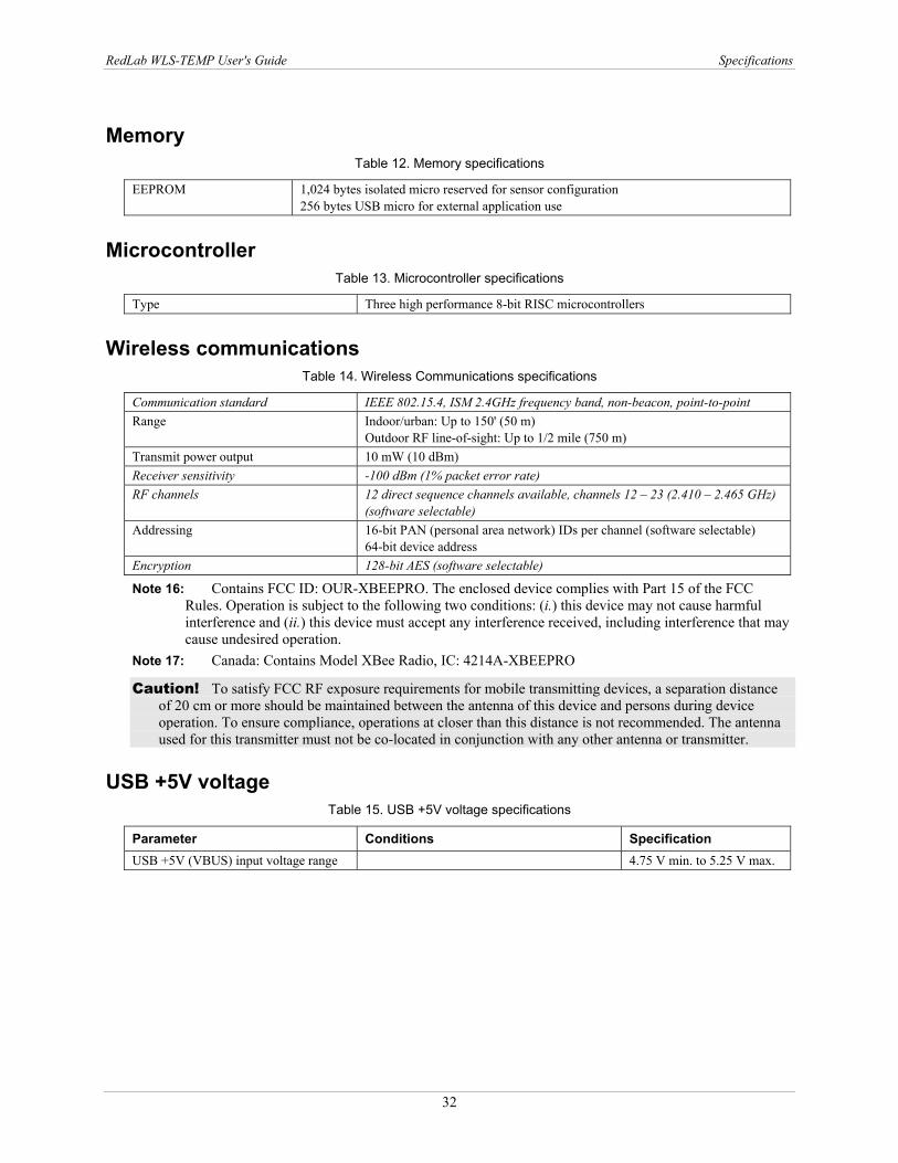
Memory Table 12. Memory specifications
EEPROM 1,024 bytes isolated micro reserved for sensor configuration 256 bytes USB micro for external application use
Microcontroller Table 13. Microcontroller specifications
Type Three high performance 8-bit RISC microcontrollers
Wireless communications Table 14. Wireless Communications specifications
Communication standard IEEE 802.15.4, ISM 2.4GHz frequency band, non-beacon, point-to-point Range Indoor/urban: Up to 150' (50 m)
Outdoor RF line-of-sight: Up to 1/2 mile (750 m) Transmit power output 10 mW (10 dBm) Receiver sensitivity -100 dBm (1% packet error rate) RF channels 12 direct sequence channels available, channels 12 – 23 (2.410 – 2.465 GHz)
(software selectable) Addressing 16-bit PAN (personal area network) IDs per channel (software selectable)
64-bit device address Encryption 128-bit AES (software selectable)
Note 16: Contains FCC ID: OUR-XBEEPRO. The enclosed device complies with Part 15 of the FCC Rules. Operation is subject to the following two conditions: (i.) this device may not cause harmful interference and (ii.) this device must accept any interference received, including interference that may cause undesired operation.
Note 17: Canada: Contains Model XBee Radio, IC: 4214A-XBEEPRO
Caution! To satisfy FCC RF exposure requirements for mobile transmitting devices, a separation distance of 20 cm or more should be maintained between the antenna of this device and persons during device operation. To ensure compliance, operations at closer than this distance is not recommended. The antenna used for this transmitter must not be co-located in conjunction with any other antenna or transmitter.
USB +5V voltage Table 15. USB +5V voltage specifications
Parameter Conditions Specification USB +5V (VBUS) input voltage range 4.75 V min. to 5.25 V max.

RedLab WLS-TEMP User's Guide Specifications
33
Power Table 16. Power specifications
Parameter Conditions Specification
Connected to USB Supply current 500 mA max. User +5V output voltage range (terminal block pin 21 and 47)
Connected to a self-powered hub. (Note 18) 4.75 V min. to 5.25 V max.
User +5V output current (terminal block pin 21 and pin 47)
Connected to a self-powered hub. (Note 18) 10 mA max.
Isolation Measurement system to PC 500 VDC min.
Wireless Communications operation Supply current 500 mA max.
AC Adapter Power Supply (used for remote wireless communications operation) Standalone power supply USB power adapter
2.5 Watt USB adapter with interchangeable plugs (Includes plug for USA)
Output voltage 5 V ±5% Output wattage 2.5 W Input voltage 100 – 240 VAC
50 – 60 Hz Input current 0.2 A
Note 18: Self-Powered Hub refers to a USB hub with an external power supply. Self-powered hubs allow a connected USB device to draw up to 500 mA. This device may not be used with bus-powered hubs due to the power supply requirements. Root Port Hubs reside in the PC’s USB Host Controller. The USB port(s) on your PC are root port hubs. All externally powered root port hubs (desktop PC's) provide up to 500 mA of current for a USB device. Battery-powered root port hubs provide 100 mA or 500 mA, depending upon the manufacturer. A laptop PC that is not connected to an external power adapter is an example of a battery-powered root port hub.
USB specifications Table 17. USB specifications
USB device type USB 2.0 (full-speed) Device compatibility USB 1.1, USB 2.0 Bus powered, 500 mA consumption max USB cable type A-B cable, UL type AWM 2725 or equivalent. (min 24 AWG VBUS/GND,
min 28 AWG D+/D-) USB cable length 3 meters max.
RedLab WLS-TEMP User's Guide Specifications
34
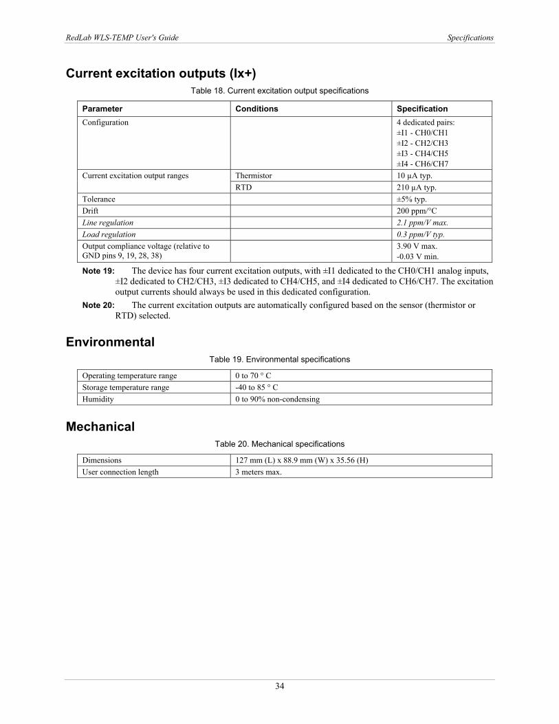
Current excitation outputs (Ix+) Table 18. Current excitation output specifications
Parameter Conditions Specification Configuration 4 dedicated pairs:
±I1 - CH0/CH1 ±I2 - CH2/CH3 ±I3 - CH4/CH5 ±I4 - CH6/CH7
Thermistor 10 µA typ. Current excitation output ranges RTD 210 µA typ.
Tolerance ±5% typ. Drift 200 ppm/°C Line regulation 2.1 ppm/V max. Load regulation 0.3 ppm/V typ. Output compliance voltage (relative to GND pins 9, 19, 28, 38)
3.90 V max. -0.03 V min.
Note 19: The device has four current excitation outputs, with ±I1 dedicated to the CH0/CH1 analog inputs, ±I2 dedicated to CH2/CH3, ±I3 dedicated to CH4/CH5, and ±I4 dedicated to CH6/CH7. The excitation output currents should always be used in this dedicated configuration.
Note 20: The current excitation outputs are automatically configured based on the sensor (thermistor or RTD) selected.
Environmental Table 19. Environmental specifications
Operating temperature range 0 to 70 ° C Storage temperature range -40 to 85 ° C Humidity 0 to 90% non-condensing
Mechanical Table 20. Mechanical specifications
Dimensions 127 mm (L) x 88.9 mm (W) x 35.56 (H) User connection length 3 meters max.
RedLab WLS-TEMP User's Guide Specifications
35
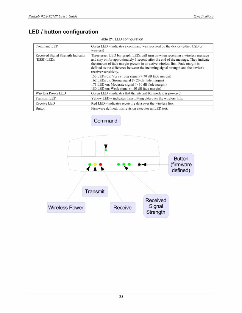
LED / button configuration Table 21. LED configuration
Command LED Green LED – indicates a command was received by the device (either USB or wireless)
Received Signal Strength Indicator (RSSI) LEDs
Three green LED bar graph. LEDs will turn on when receiving a wireless message and stay on for approximately 1 second after the end of the message. They indicate the amount of fade margin present in an active wireless link. Fade margin is defined as the difference between the incoming signal strength and the device's receiver sensitivity. 153 LEDs on: Very strong signal (> 30 dB fade margin) 162 LEDs on: Strong signal (> 20 dB fade margin) 171 LED on: Moderate signal (> 10 dB fade margin) 180 LED on: Weak signal (< 10 dB fade margin)
Wireless Power LED Green LED – indicates that the internal RF module is powered. Transmit LED Yellow LED – indicates transmitting data over the wireless link. Receive LED Red LED – indicates receiving data over the wireless link. Button Firmware defined; this revision executes an LED test.
Command
Wireless Power
Transmit
ReceiveReceived
SignalStrength
Button(firmwaredefined)
RedLab WLS-TEMP User's Guide Specifications
36
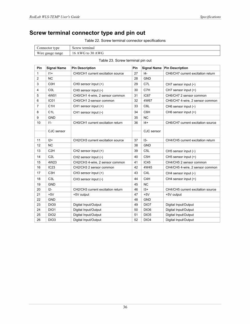
Screw terminal connector type and pin out Table 22. Screw terminal connector specifications
Connector type Screw terminal Wire gauge range 16 AWG to 30 AWG
Table 23. Screw terminal pin out
Pin Signal Name Pin Description Pin Signal Name Pin Description 1 I1+ CH0/CH1 current excitation source 27 I4- CH6/CH7 current excitation return 2 NC 28 GND
3 C0H CH0 sensor input (+) 29 C7L CH7 sensor input (-) 4 C0L CH0 sensor input (-) 30 C7H CH7 sensor input (+)
5 4W01 CH0/CH1 4-wire, 2 sensor common 31 IC67 CH6/CH7 2 sensor common 6 IC01 CH0/CH1 2-sensor common 32 4W67 CH6/CH7 4-wire, 2 sensor common
7 C1H CH1 sensor input (+) 33 C6L CH6 sensor input (-) 8 C1L CH1 sensor input (-) 34 C6H CH6 sensor input (+)
9 GND 35 NC 10 I1- CH0/CH1 current excitation return 36 I4+ CH6/CH7 current excitation source
CJC sensor
CJC sensor
11 I2+ CH2/CH3 current excitation source 37 I3- CH4/CH5 current excitation return 12 NC 38 GND
13 C2H CH2 sensor input (+) 39 C5L CH5 sensor input (-) 14 C2L CH2 sensor input (-) 40 C5H CH5 sensor input (+)
15 4W23 CH2/CH3 4-wire, 2 sensor common 41 IC45 CH4/CH5 2 sensor common 16 IC23 CH2/CH3 2 sensor common 42 4W45 CH4/CH5 4-wire, 2 sensor common
17 C3H CH3 sensor input (+) 43 C4L CH4 sensor input (-) 18 C3L CH3 sensor input (-) 44 C4H CH4 sensor input (+)
19 GND 45 NC 20 I2- CH2/CH3 current excitation return 46 I3+ CH4/CH5 current excitation source 21 +5V +5V output 47 +5V +5V output 22 GND 48 GND 23 DIO0 Digital Input/Output 49 DIO7 Digital Input/Output 24 DIO1 Digital Input/Output 50 DIO6 Digital Input/Output 25 DIO2 Digital Input/Output 51 DIO5 Digital Input/Output 26 DIO3 Digital Input/Output 52 DIO4 Digital Input/Output

Meilhaus Electronic GmbH Am Sonnenlicht 2 D-82239 Alling, Germany Phone: +49 (0)8141 - 5271-0 Fax: +49 (0)8141 - 5271-129E-Mail: [email protected] http://www.meilhaus.com