
Redington Counters Redington
108
www.redingtoncounters.com ABOUT REDINGTON Since 1961 REDINGTON has offered products that have proven to be rugged and manufactured to the highest quality standards. Over several decades we have focused on bringing our customers quality products at competitive prices. This catalog contains several new and innovative products confirming our commitment to provide state-of-the-art solutions for our customers. Over the past few years, we have committed to developing the capabilities to provide the finest electronic solutions for our customers’ counting, elapsed time indicating and controlling needs. We have done this while continuing to supply and support our broad range of rugged mechanical and electromechanical products. We stand ready to work with our customers to provide cost effective solutions and to match the best technology with your applications. CUSTOMER SERVICE We are committed to providing the best customer service anywhere. We strive to provide our customers with prompt replies, on time delivery and hassle free customer satisfaction. Our goals are to serve our customers and take the extra steps necessary to satisfy your requirements. We provide field assistance backed up by competent technical support from our headquarters location. We have Authorized Distributors and Representatives throughout North America that stand ready to assist our customers. Contact your local Sales Representative, or call us at the factory, to get the name of your nearest authorized distributor. REDINGTON COUNTERS, INC. P.O. Box 608 130 Addison Road Windsor, CT 06095 on the web... web site: www.redingtoncounters.com e-mail: [email protected] (800) 395-7337 (860) 688-6205 Fax: (860) 688-1591 How to Contact Us by Mail... by Phone... by Fax... Customer Service/Application Assistance
description
Redington Counters Redington Industrial Electronics Catalog
Transcript of Redington Counters Redington

www.redingtoncounters.com
ABOUT REDINGTON
Since 1961 REDINGTON has offered products that have proven to be ruggedand manufactured to the highest quality standards. Over several decades wehave focused on bringing our customers quality products at competitive prices.This catalog contains several new and innovative products confirming ourcommitment to provide state-of-the-art solutions for our customers.
Over the past few years, we have committed to developing the capabilities toprovide the finest electronic solutions for our customers’ counting, elapsed timeindicating and controlling needs. We have done this while continuing to supplyand support our broad range of rugged mechanical and electromechanicalproducts. We stand ready to work with our customers to provide cost effectivesolutions and to match the best technology with your applications.
CUSTOMER SERVICE
We are committed to providing the best customer service anywhere. We strive toprovide our customers with prompt replies, on time delivery and hassle freecustomer satisfaction. Our goals are to serve our customers and take the extrasteps necessary to satisfy your requirements.
We provide field assistance backed up by competent technical support from ourheadquarters location. We have Authorized Distributors and Representativesthroughout North America that stand ready to assist our customers. Contact yourlocal Sales Representative, or call us at the factory, to get the name of yournearest authorized distributor.
REDINGTON COUNTERS, INC.P.O. Box 608130 Addison RoadWindsor, CT 06095
on the web...
web site: www.redingtoncounters.come-mail: [email protected]
(800) 395-7337(860) 688-6205
Fax: (860) 688-1591
How to Contact Us
by Mail...
by Phone... by Fax...
Customer Service/Application Assistance
www.redingtoncounters.com
Table of Contents
Page#
Introduction 4
COUNTERSElectronic
Model 33 LCD 8 digits, self powered 8Model 3302 LCD Large 4 digit display PCB Mount, self powered 10Model 52 LCD 8 digits, uni or bi-directional 11Model 53 LCD 7 or 8 digits, self powered, AC, DC or switch input 13Model 54 LCD 7 or 8 digits, PCB module, self-powered 15Model 55 7 digits, 3 mountings, AC/DC, EEPROM, reset 52Model 56 7 digits, 3 mountings, AC/DC, EEPROM, reset, “Alerts” 55Model 57 7 digits, 3 mountings, DC, EEPROM, reset, multi-function, 1 or 2 displays 58Model 59 7 digits, PCB mount, DC, EEPROM, reset, multi-function 61Model 88 LCD 8 digits, EEPROM, multifunction, uni or bi- directional 85Model 94 LCD 6 digits, 3 mountings, reset, large figures 16
ElectromechanicalModel 10 General-purpose totalizer, 6 figures, versatile mountings 19Model 10 General-purpose totalizer, 7 figures, versatile mountings 20Model 40 Low cost, 6 or 7 figures, non-reset 21Model 44 6 figures, non-reset 23Model 48 Compact 6 or 7 figures, non-reset 24Model 49 4 or 6 figures, push-button reset 26Model 128 4 figures, rotary reset, panel or base mount 28Model 300 6 figures, panel mount, push-button reset 29
MechanicalModel 08 Rotary counter 30Model 14 Small, rotary or stroke counter 31Model 20 Medium duty, stroke counter 35Model 22 Medium duty, rotary counter 36Model 27 Heavy-duty, stroke counter, 5 figures 37Model 28 Heavy-duty, stroke counter, 5 figures 38Model 29 Heavy-duty, stroke counter, 6 figures 39Model 29 Heavy-duty, rotary counter, 6 figures 40Model 41 Combined register and totalizer, 3 or 4 figures 41Model 46 Compact, 5 figure, stroke counter 42Model 750 Rugged revolution counter 43Model PCU Stroke counter, 3 or 4 figures 44
Hand Tally CountersModel 18 Hand Tally counters 33Model 19 Modular Tally counters 34Model 46T Compact stroke counter with thumb lever, 5 figures 42Model E1 LCD Hand Tally, 4 digits, self powered 17Model E2/E3 LCD ADD and ADD/SUBTRACT 4 digit Hand Tally 18
PREDETERMINING COUNTERSElectronic
Model 83 LCD 6 digits, 1/16 DIN, preset & batch counter, EEPROM, AC/DC 89Model 88 LCD 8 digits, serial communications, EEPROM, AC/DC, analog I/O 85
ElectromechanicalModel 58 4 or 6 figures, panel mount, SPDT switch 45
NEW!
NEW!
NEW!
www.redingtoncounters.com
Table of Contents
Page#
HOUR METERSElectronic
Model 33 6 digits, totally sealed, 4 mounting, AC/DC inputs 46Model 51 6 digits, totally sealed, 3 mountings, AC/DC/Inductive, “Alerts”, Tach. 48Model 53 7 digits, LCD, self powered, AC, DC or switch input 50Model 55 7 digits, 3 mountings, AC/DC, EEPROM, reset 52Model 56 7 digits, 3 mountings, AC/DC, EEPROM, reset, “Alerts” 55Model 57 7 digits, 3 mountings, DC, EEPROM, reset, multi-function, 1 or 2 displays 58Model 59 7 digits, PCB mount, DC, EEPROM, reset, multi-function 61Model 88 6 digits, panel mount, Hrs, Min., Sec., serial communications, EEPROM 87Model 94 6 digits, 3 mountings, reset, large figures 63Model 720 7 digits, rugged steel housing 64
ElectromechanicalModel 77 6 figures, non-reset, panel mount 65Model 710 5 figures reset, 6 figure non-reset, AC voltage, 3-Hole mount 66Model 711/731 7 figures, non-reset, AC/DC voltages 67Model 711/731 7 figures, non-reset, AC/DC voltages, distinctive styling 69Model 711 6 or 7 figures, reset or non-reset, AC voltage, rectangular styling 70Model 720 5 or 6 figures, rugged steel housing, designed to mil-spec. 71Model 722 6 figures, totally sealed AC Hour Meter, 115/230VAC, 50/60Hz 72Model 732 6 figures, totally sealed DC Hour Meter, 10-80 VDC 74
PREDETERMINING TIMERSElectronic
Model 83 6 digits, 1/16 DIN, EEPROM, serial communications 94Model 88 8 digits, EEPROM, serial communications 85
CONTROLLERS & INDICATORSElectronic
Model 53 Tachometer, 4 digits, LCD, self powered, AC/DC inputs 76Model 85 4 digits, 1/8 DIN, RED or Green display, input scaling, EEPROM 78Model 88 8 digits, panel mount, serial communications, input scaling, EEPROM 85Model 92 Hand Held Tachometer/LCD, rotary and linear speed indicator 98
DIGITAL PANEL METERSElectronic
Model 85 3 1/2 digits, 1/8 DIN, temperature, rate, freq., volts, amps, ohms, modular 78
ENCODERS/SENSORS
Model 65 Incremental optical encoder, uni or bi-directional 100Model 65 Proximity switch, DC voltage, for counting or rate input 101
APPENDICESGlossary of terms 102Part# Index 106
NEW!
NEW!
NEW!
www.redingtoncounters.com4
Introduction
TOTALIZING COUNTERS
Totalizing counters are used to sum the total number ofcycles or inputs to a device. These counters have no“outputs”. Totalizers can be Mechanical, Electromechanicalor Electronic.
Totalizers are typically used to total cycle count, piececount, and linear length or to indicate position. Displays forMechanical & Electromechanical Totalizers are moldedfigure wheels usually displaying 0-9 digits on a contrastingbackground and have a count capacity of 3-8 figures.
Mechanical Totalizers
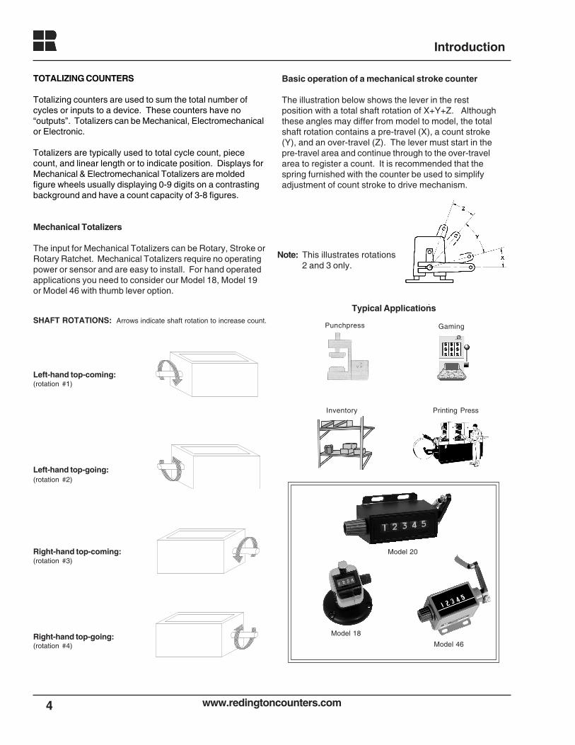
The input for Mechanical Totalizers can be Rotary, Stroke orRotary Ratchet. Mechanical Totalizers require no operatingpower or sensor and are easy to install. For hand operatedapplications you need to consider our Model 18, Model 19or Model 46 with thumb lever option.
Right-hand top-going:(rotation #4)
Right-hand top-coming:(rotation #3)
Basic operation of a mechanical stroke counter
The illustration below shows the lever in the restposition with a total shaft rotation of X+Y+Z. Althoughthese angles may differ from model to model, the totalshaft rotation contains a pre-travel (X), a count stroke(Y), and an over-travel (Z). The lever must start in thepre-travel area and continue through to the over-travelarea to register a count. It is recommended that thespring furnished with the counter be used to simplifyadjustment of count stroke to drive mechanism.
Left-hand top-coming:(rotation #1)
Left-hand top-going:(rotation #2)
Note: This illustrates rotations2 and 3 only.
SHAFT ROTATIONS: Arrows indicate shaft rotation to increase count.
Model 20
Model 18
Model 46
Punchpress Gaming
Inventory Printing Press
Typical Applications
www.redingtoncounters.com 5
Introduction
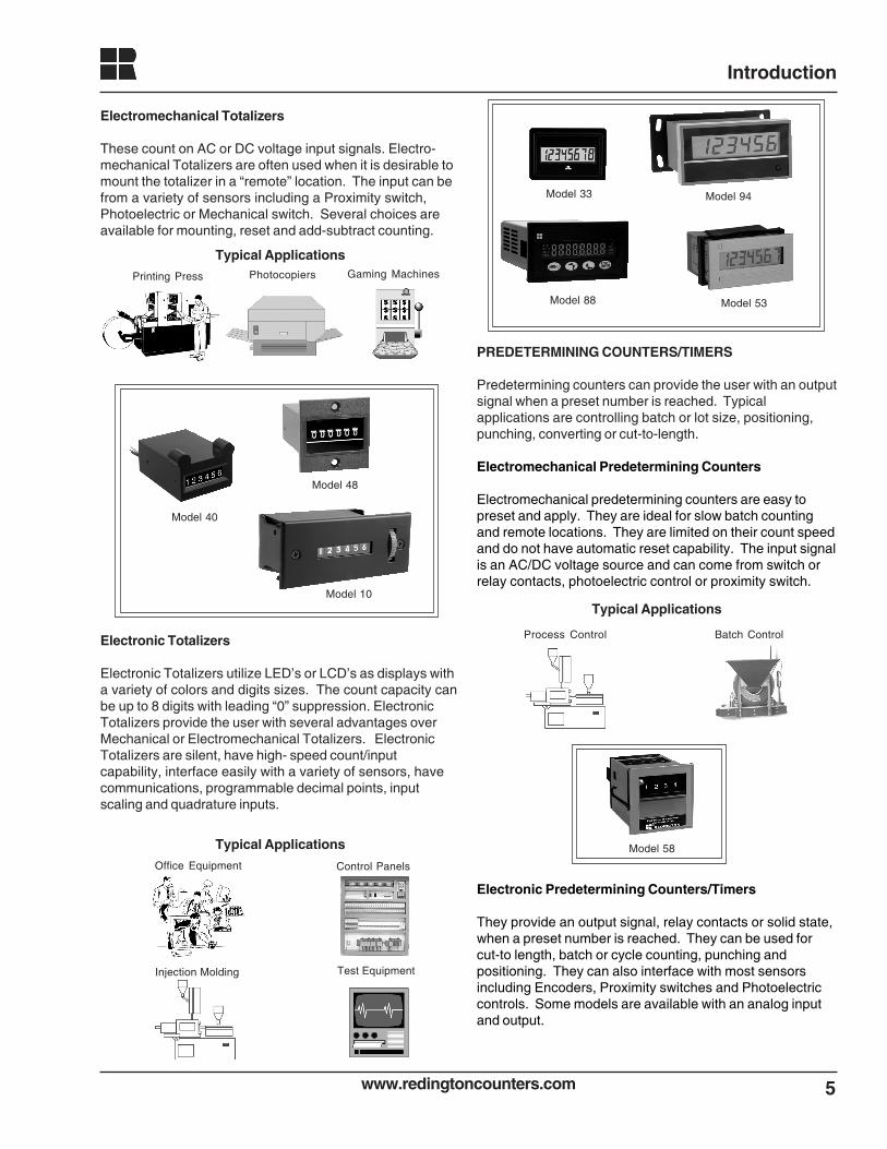
Electromechanical Totalizers
These count on AC or DC voltage input signals. Electro-mechanical Totalizers are often used when it is desirable tomount the totalizer in a “remote” location. The input can befrom a variety of sensors including a Proximity switch,Photoelectric or Mechanical switch. Several choices areavailable for mounting, reset and add-subtract counting.
Electronic Totalizers
Electronic Totalizers utilize LED’s or LCD’s as displays witha variety of colors and digits sizes. The count capacity canbe up to 8 digits with leading “0” suppression. ElectronicTotalizers provide the user with several advantages overMechanical or Electromechanical Totalizers. ElectronicTotalizers are silent, have high- speed count/inputcapability, interface easily with a variety of sensors, havecommunications, programmable decimal points, inputscaling and quadrature inputs.
PREDETERMINING COUNTERS/TIMERS
Predetermining counters can provide the user with an outputsignal when a preset number is reached. Typicalapplications are controlling batch or lot size, positioning,punching, converting or cut-to-length.
Electromechanical Predetermining Counters
Electromechanical predetermining counters are easy topreset and apply. They are ideal for slow batch countingand remote locations. They are limited on their count speedand do not have automatic reset capability. The input signalis an AC/DC voltage source and can come from switch orrelay contacts, photoelectric control or proximity switch.
Model 33
Model 53Model 88
Model 94
Control Panels
Injection Molding Test Equipment
Office Equipment
Typical Applications
Typical ApplicationsGaming MachinesPhotocopiersPrinting Press
Typical Applications
Batch ControlProcess Control
Electronic Predetermining Counters/Timers
They provide an output signal, relay contacts or solid state,when a preset number is reached. They can be used forcut-to length, batch or cycle counting, punching andpositioning. They can also interface with most sensorsincluding Encoders, Proximity switches and Photoelectriccontrols. Some models are available with an analog inputand output.
Model 58
Model 48
Model 40
Model 10
www.redingtoncounters.com6
Introduction
Typical Applications
Models 83 Models 88
Cut-to-Length Batching
Typical Applications
Model 92Model 88Model 85
Hand-Held Tachometer
Flow Level and Control Temperature
Model 85
Typical ApplicationsTemperature Volts/Amps
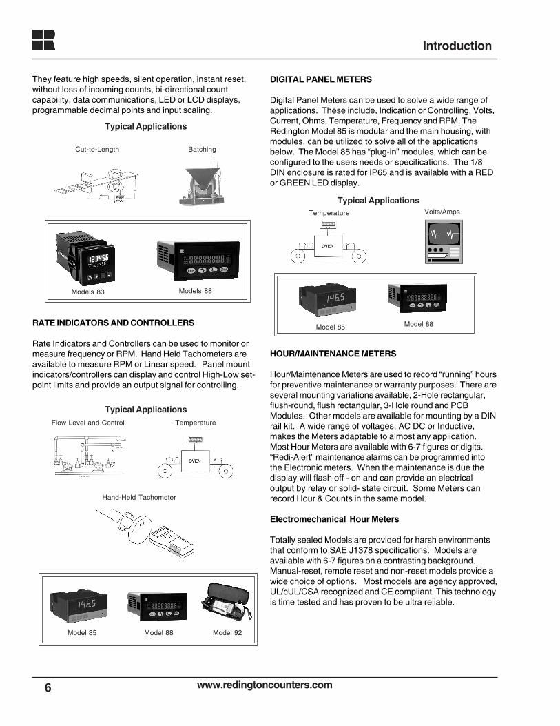
They feature high speeds, silent operation, instant reset,without loss of incoming counts, bi-directional countcapability, data communications, LED or LCD displays,programmable decimal points and input scaling.
RATE INDICATORS AND CONTROLLERS
Rate Indicators and Controllers can be used to monitor ormeasure frequency or RPM. Hand Held Tachometers areavailable to measure RPM or Linear speed. Panel mountindicators/controllers can display and control High-Low set-point limits and provide an output signal for controlling.
DIGITAL PANEL METERS
Digital Panel Meters can be used to solve a wide range ofapplications. These include, Indication or Controlling, Volts,Current, Ohms, Temperature, Frequency and RPM. TheRedington Model 85 is modular and the main housing, withmodules, can be utilized to solve all of the applicationsbelow. The Model 85 has “plug-in” modules, which can beconfigured to the users needs or specifications. The 1/8DIN enclosure is rated for IP65 and is available with a REDor GREEN LED display.
HOUR/MAINTENANCE METERS
Hour/Maintenance Meters are used to record “running” hoursfor preventive maintenance or warranty purposes. There areseveral mounting variations available, 2-Hole rectangular,flush-round, flush rectangular, 3-Hole round and PCBModules. Other models are available for mounting by a DINrail kit. A wide range of voltages, AC DC or Inductive,makes the Meters adaptable to almost any application.Most Hour Meters are available with 6-7 figures or digits.“Redi-Alert” maintenance alarms can be programmed intothe Electronic meters. When the maintenance is due thedisplay will flash off - on and can provide an electricaloutput by relay or solid- state circuit. Some Meters canrecord Hour & Counts in the same model.
Electromechanical Hour Meters
Totally sealed Models are provided for harsh environmentsthat conform to SAE J1378 specifications. Models areavailable with 6-7 figures on a contrasting background.Manual-reset, remote reset and non-reset models provide awide choice of options. Most models are agency approved,UL/cUL/CSA recognized and CE compliant. This technologyis time tested and has proven to be ultra reliable.
Model 88
www.redingtoncounters.com 7
Introduction
Typical Applications
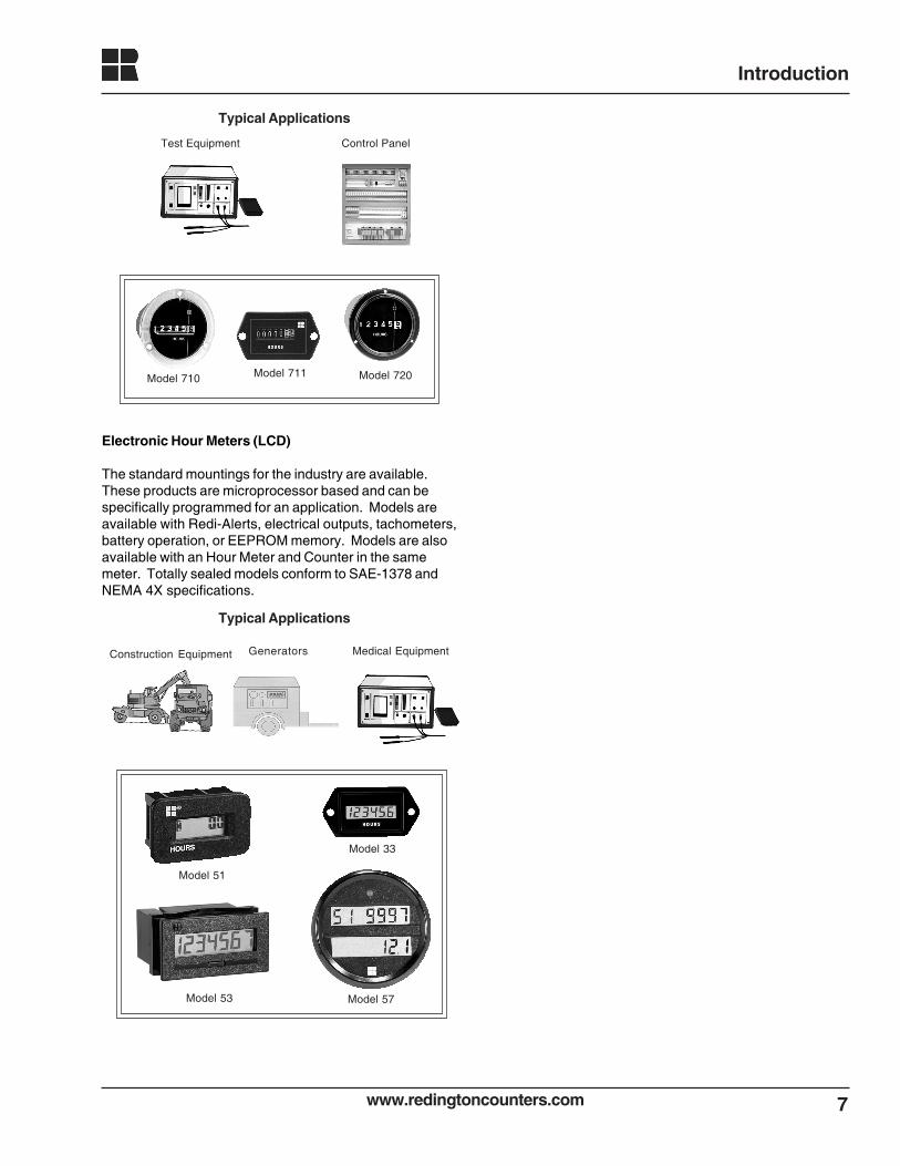
Model 711 Model 720Model 710
Test Equipment Control Panel
Electronic Hour Meters (LCD)
The standard mountings for the industry are available.These products are microprocessor based and can bespecifically programmed for an application. Models areavailable with Redi-Alerts, electrical outputs, tachometers,battery operation, or EEPROM memory. Models are alsoavailable with an Hour Meter and Counter in the samemeter. Totally sealed models conform to SAE-1378 andNEMA 4X specifications.
Typical Applications
GeneratorsConstruction Equipment Medical Equipment
Model 33
Model 53
Model 51
Model 57
www.redingtoncounters.com8
Model 33 Electronic LCD Counter
Description
Features Options
Specifications
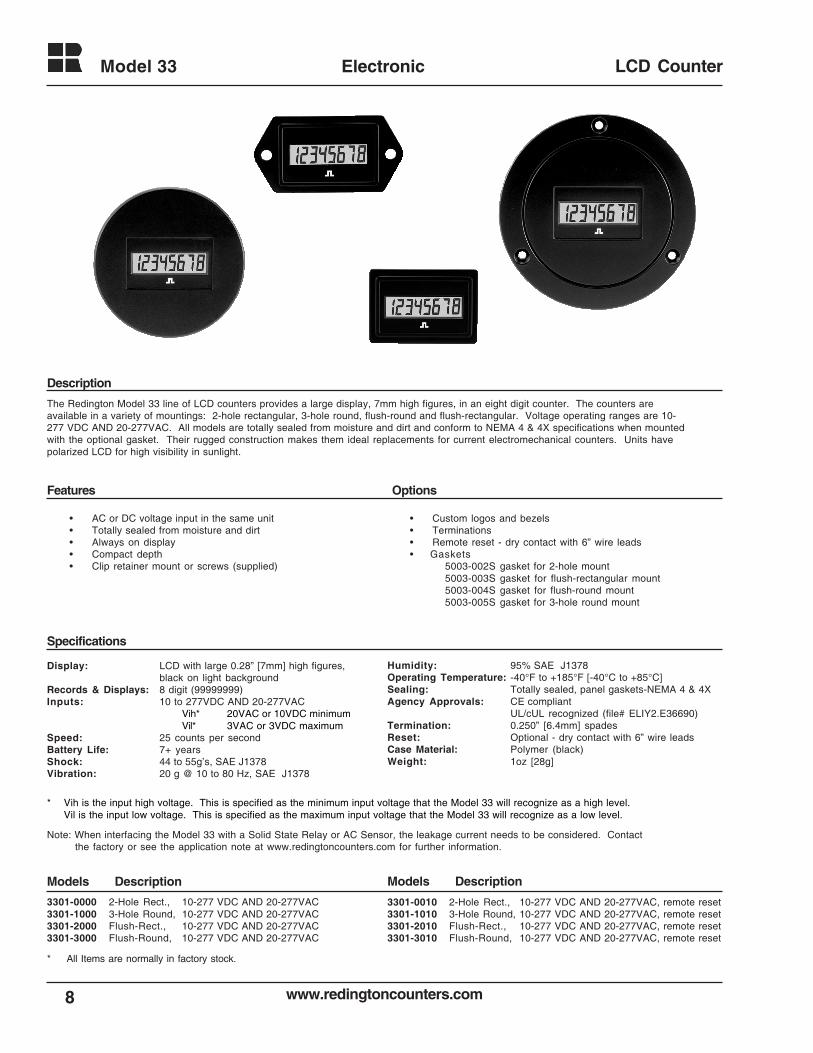
The Redington Model 33 line of LCD counters provides a large display, 7mm high figures, in an eight digit counter. The counters areavailable in a variety of mountings: 2-hole rectangular, 3-hole round, flush-round and flush-rectangular. Voltage operating ranges are 10-277 VDC AND 20-277VAC. All models are totally sealed from moisture and dirt and conform to NEMA 4 & 4X specifications when mountedwith the optional gasket. Their rugged construction makes them ideal replacements for current electromechanical counters. Units havepolarized LCD for high visibility in sunlight.
• AC or DC voltage input in the same unit• Totally sealed from moisture and dirt• Always on display• Compact depth• Clip retainer mount or screws (supplied)
• Custom logos and bezels• Terminations• Remote reset - dry contact with 6” wire leads• Gaskets
5003-002S gasket for 2-hole mount5003-003S gasket for flush-rectangular mount5003-004S gasket for flush-round mount5003-005S gasket for 3-hole round mount
Display: LCD with large 0.28” [7mm] high figures,black on light background
Records & Displays: 8 digit (99999999)Inputs: 10 to 277VDC AND 20-277VAC
Vih* 20VAC or 10VDC minimumVil* 3VAC or 3VDC maximum
Speed: 25 counts per secondBattery Life: 7+ yearsShock: 44 to 55g’s, SAE J1378Vibration: 20 g @ 10 to 80 Hz, SAE J1378
Humidity: 95% SAE J1378Operating Temperature: -40°F to +185°F [-40°C to +85°C]Sealing: Totally sealed, panel gaskets-NEMA 4 & 4XAgency Approvals: CE compliant
UL/cUL recognized (file# ELIY2.E36690)Termination: 0.250” [6.4mm] spadesReset: Optional - dry contact with 6” wire leadsCase Material: Polymer (black)Weight: 1oz [28g]
3301-0000 2-Hole Rect., 10-277 VDC AND 20-277VAC3301-1000 3-Hole Round, 10-277 VDC AND 20-277VAC3301-2000 Flush-Rect., 10-277 VDC AND 20-277VAC3301-3000 Flush-Round, 10-277 VDC AND 20-277VAC
* Vih is the input high voltage. This is specified as the minimum input voltage that the Model 33 will recognize as a high level.Vil is the input low voltage. This is specified as the maximum input voltage that the Model 33 will recognize as a low level.
3301-0010 2-Hole Rect., 10-277 VDC AND 20-277VAC, remote reset3301-1010 3-Hole Round, 10-277 VDC AND 20-277VAC, remote reset3301-2010 Flush-Rect., 10-277 VDC AND 20-277VAC, remote reset3301-3010 Flush-Round, 10-277 VDC AND 20-277VAC, remote reset
Models Description Models Description
Note: When interfacing the Model 33 with a Solid State Relay or AC Sensor, the leakage current needs to be considered. Contactthe factory or see the application note at www.redingtoncounters.com for further information.
* All Items are normally in factory stock.
9
Model 33 Electronic
www.redingtoncounters.com
LCD Counter
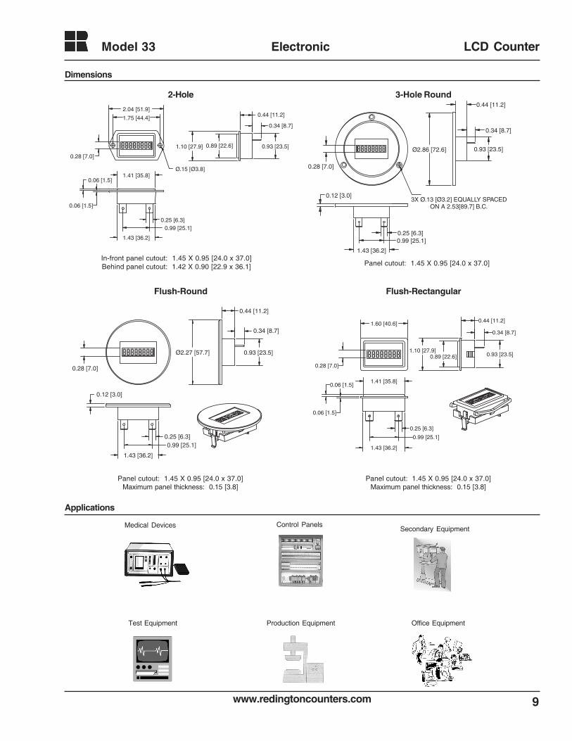
Dimensions
Applications
2-Hole 3-Hole Round
Flush-Round Flush-Rectangular
Medical Devices Control Panels
Production EquipmentTest Equipment Office Equipment
In-front panel cutout: 1.45 X 0.95 [24.0 x 37.0]Behind panel cutout: 1.42 X 0.90 [22.9 x 36.1]
Secondary Equipment
Panel cutout: 1.45 X 0.95 [24.0 x 37.0]
Panel cutout: 1.45 X 0.95 [24.0 x 37.0]Maximum panel thickness: 0.15 [3.8]
Panel cutout: 1.45 X 0.95 [24.0 x 37.0]Maximum panel thickness: 0.15 [3.8]
0.25 [6.3]
1.43 [36.2]
0.99 [25.1]
0.12 [3.0]
0.34 [8.7]
0.93 [23.5]
0.44 [11.2]
Ø2.27 [57.7]
0.28 [7.0]
0.28 [7.0]
2.04 [51.9]
1.75 [44.4]
Ø.15 [Ø3.8]
1.10 [27.9]
0.44 [11.2]
0.34 [8.7]
0.93 [23.5]
0.25 [6.3]
1.43 [36.2]
0.99 [25.1]
0.06 [1.5]
0.06 [1.5]1.41 [35.8]
0.89 [22.6]
0.28 [7.0]
0.12 [3.0]
0.25 [6.3]0.99 [25.1]
1.43 [36.2]
Ø2.86 [72.6] 0.93 [23.5]
0.34 [8.7]
0.44 [11.2]
3X Ø.13 [Ø3.2] EQUALLY SPACED ON A 2.53[89.7] B.C.
0.28 [7.0]
1.60 [40.6]
1.10 [27.9]
0.44 [11.2]
0.34 [8.7]
0.93 [23.5]
0.06 [1.5]
0.06 [1.5]
1.43 [36.2]
0.99 [25.1]
0.25 [6.3]
1.41 [35.8]
0.89 [22.6]
www.redingtoncounters.com
Model 3302
10
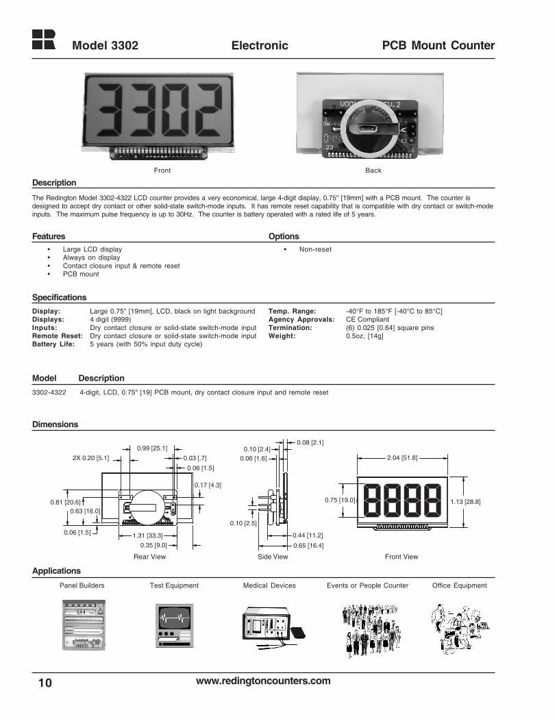
Electronic PCB Mount Counter
3302-4322 4-digit, LCD, 0.75" [19] PCB mount, dry contact closure input and remote reset
Description
Features Options
Specifications
Model Description
Dimensions
Applications
The Redington Model 3302-4322 LCD counter provides a very economical, large 4-digit display, 0.75" [19mm] with a PCB mount. The counter isdesigned to accept dry contact or other solid-state switch-mode inputs. It has remote reset capability that is compatible with dry contact or switch-modeinputs. The maximum pulse frequency is up to 30Hz. The counter is battery operated with a rated life of 5 years.
• Large LCD display• Always on display• Contact closure input & remote reset• PCB mount
• Non-reset
Display: Large 0.75" [19mm], LCD, black on light backgroundDisplays: 4 digit (9999)Inputs: Dry contact closure or solid-state switch-mode inputRemote Reset: Dry contact closure or solid-state switch-mode inputBattery Life: 5 years (with 50% input duty cycle)
Temp. Range: -40°F to 185°F [-40°C to 85°C]Agency Approvals: CE CompliantTermination: (6) 0.025 [0.64] square pinsWeight: 0.5oz, [14g]
Panel Builders Medical Devices Office EquipmentTest Equipment Events or People Counter
Rear View Side View Front View
Front Back
1.31 [33.3]
0.35 [9.0]
0.06 [1.5]
0.63 [16.0]0.81 [20.6]
0.06 [1.5]
0.03 [.7]
0.99 [25.1]
2X 0.20 [5.1]
0.17 [4.3]
0.08 [2.1]0.10 [2.4]
0.06 [1.6]
0.44 [11.2]
0.65 [16.4]
0.10 [2.5]
2.04 [51.8]
1.13 [28.8]0.75 [19.0]
11www.redingtoncounters.com
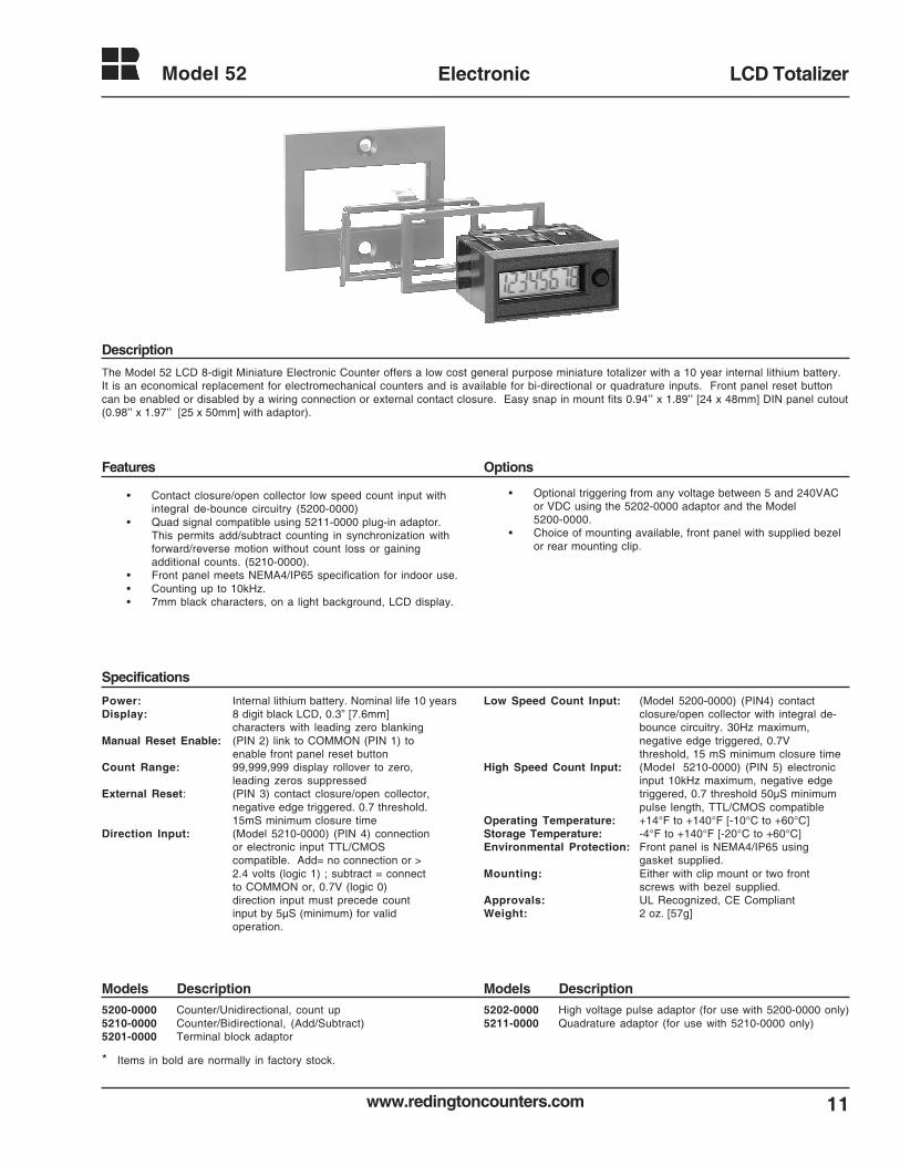
Model 52 Electronic LCD Totalizer
The Model 52 LCD 8-digit Miniature Electronic Counter offers a low cost general purpose miniature totalizer with a 10 year internal lithium battery.It is an economical replacement for electromechanical counters and is available for bi-directional or quadrature inputs. Front panel reset buttoncan be enabled or disabled by a wiring connection or external contact closure. Easy snap in mount fits 0.94’’ x 1.89’’ [24 x 48mm] DIN panel cutout(0.98’’ x 1.97’’ [25 x 50mm] with adaptor).
• Contact closure/open collector low speed count input withintegral de-bounce circuitry (5200-0000)
• Quad signal compatible using 5211-0000 plug-in adaptor.This permits add/subtract counting in synchronization withforward/reverse motion without count loss or gainingadditional counts. (5210-0000).
• Front panel meets NEMA4/IP65 specification for indoor use.• Counting up to 10kHz.• 7mm black characters, on a light background, LCD display.
Power: Internal lithium battery. Nominal life 10 yearsDisplay: 8 digit black LCD, 0.3” [7.6mm]
characters with leading zero blankingManual Reset Enable: (PIN 2) link to COMMON (PIN 1) to
enable front panel reset buttonCount Range: 99,999,999 display rollover to zero,
leading zeros suppressedExternal Reset: (PIN 3) contact closure/open collector,
negative edge triggered. 0.7 threshold.15mS minimum closure time
Direction Input: (Model 5210-0000) (PIN 4) connectionor electronic input TTL/CMOScompatible. Add= no connection or >2.4 volts (logic 1) ; subtract = connectto COMMON or, 0.7V (logic 0)direction input must precede countinput by 5µS (minimum) for validoperation.
• Optional triggering from any voltage between 5 and 240VACor VDC using the 5202-0000 adaptor and the Model5200-0000.
• Choice of mounting available, front panel with supplied bezelor rear mounting clip.
5200-0000 Counter/Unidirectional, count up5210-0000 Counter/Bidirectional, (Add/Subtract)5201-0000 Terminal block adaptor
5202-0000 High voltage pulse adaptor (for use with 5200-0000 only)5211-0000 Quadrature adaptor (for use with 5210-0000 only)
Description
Features Options
Specifications
Models DescriptionModels Description
Low Speed Count Input: (Model 5200-0000) (PIN4) contactclosure/open collector with integral de-bounce circuitry. 30Hz maximum,negative edge triggered, 0.7Vthreshold, 15 mS minimum closure time
High Speed Count Input: (Model 5210-0000) (PIN 5) electronicinput 10kHz maximum, negative edgetriggered, 0.7 threshold 50µS minimumpulse length, TTL/CMOS compatible
Operating Temperature: +14°F to +140°F [-10°C to +60°C]Storage Temperature: -4°F to +140°F [-20°C to +60°C]Environmental Protection: Front panel is NEMA4/IP65 using
gasket supplied.Mounting: Either with clip mount or two front
screws with bezel supplied.Approvals: UL Recognized, CE CompliantWeight: 2 oz. [57g]
* Items in bold are normally in factory stock.
www.redingtoncounters.com
Model 52
12
Electronic LCD Totalizer
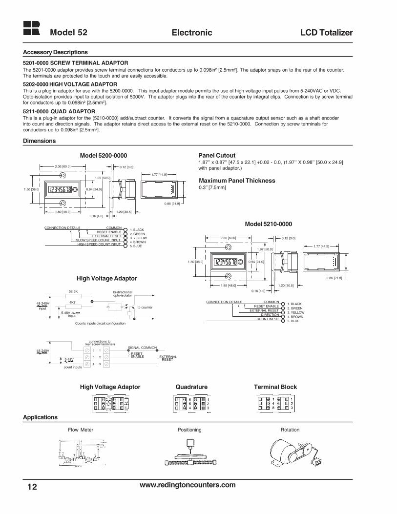
Dimensions
1.77 [44.9]
0.86 [21.9]
1.20 [30.5]0.16 [4.0]
0.94 [24.0]
1.97 [50.0]
1.50 [38.0]
1.89 [48.0]
2.36 [60.0] 0.12 [3.0]
COMMONRESET ENABLE
EXTERNAL RESETSLOW SPEED COUNT INPUTHIGH SPEED COUNT INPUT
1. BLACK2. GREEN3. YELLOW4. BROWN5. BLUE
CONNECTION DETAILS
1.77 [44.9]
0.86 [21.9]
1.20 [30.5]
0.16 [4.0]
0.94 [24.0]
1.97 [50.0]
1.50 [38.0]
1.89 [48.0]
2.36 [60.0] 0.12 [3.0]
COMMONRESET ENABLE
EXTERNAL RESETDIRECTION
COUNT INPUT
1. BLACK2. GREEN3. YELLOW4. BROWN5. BLUE
CONNECTION DETAILS48-240Vinput
5-48Vinput
to counter
opto-isotatorbi-directional58.5K
4K7
48-240V
5-48V
count inputs4 3
25
16
Counts inputs circuit configuration
connections torear screw terminals
SIGNAL COMMON
ENABLERESET
EXTERNALRESET
Model 5200-0000
Model 5210-0000
High Voltage Adaptor
Terminal Block
Panel Cutout1.87’’ x 0.87’’ [47.5 x 22.1] +0.02 - 0.0, )1.97’’ X 0.98’’ [50.0 x 24.9]with panel adaptor.)
Accessory Descriptions
5201-0000 SCREW TERMINAL ADAPTORThe 5201-0000 adaptor provides screw terminal connections for conductors up to 0.098in² [2.5mm2]. The adaptor snaps on to the rear of the counter.The terminals are protected to the touch and are easily accessible.
5202-0000 HIGH VOLTAGE ADAPTORThis is a plug in adaptor for use with the 5200-0000. This input adaptor module permits the use of high voltage input pulses from 5-240VAC or VDC.Opto-isolation provides input to output isolation of 5000V. The adaptor plugs into the rear of the counter by integral clips. Connection is by screw terminalfor conductors up to 0.098in² [2.5mm2].
5211-0000 QUAD ADAPTORThis is a plug-in adaptor for the (5210-0000) add/subtract counter. It converts the signal from a quadrature output sensor such as a shaft encoderinto count and direction signals. The adaptor retains direct access to the external reset on the 5210-0000. Connection by screw terminals forconductors up to 0.098in² [2.5mm2].
Applications
RotationPositioningFlow Meter
High Voltage Adaptor Quadrature
Maximum Panel Thickness0.3’’ [7.5mm]
www.redingtoncounters.com 13
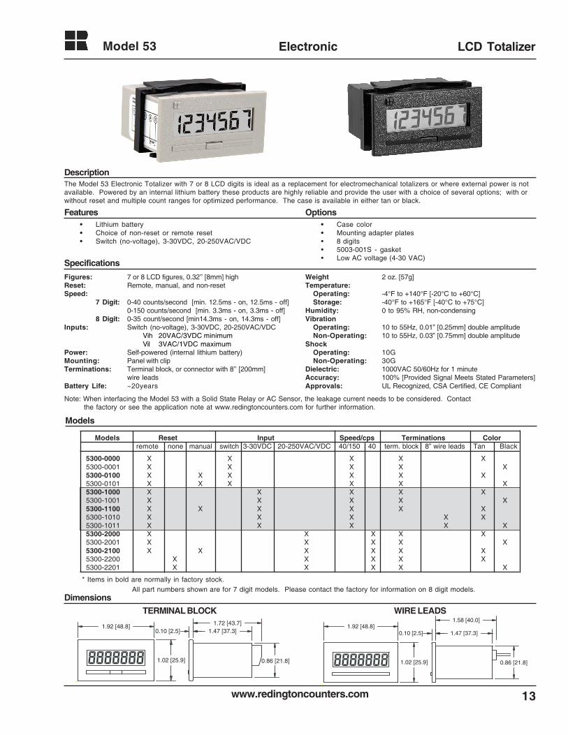
Model 53 Electronic LCD Totalizer
The Model 53 Electronic Totalizer with 7 or 8 LCD digits is ideal as a replacement for electromechanical totalizers or where external power is notavailable. Powered by an internal lithium battery these products are highly reliable and provide the user with a choice of several options; with orwithout reset and multiple count ranges for optimized performance. The case is available in either tan or black.
Weight 2 oz. [57g]Temperature:
Operating: -4°F to +140°F [-20°C to +60°C]Storage: -40°F to +165°F [-40°C to +75°C]
Humidity: 0 to 95% RH, non-condensingVibration
Operating: 10 to 55Hz, 0.01” [0.25mm] double amplitudeNon-Operating: 10 to 55Hz, 0.03” [0.75mm] double amplitude
ShockOperating: 10GNon-Operating: 30G
Dielectric: 1000VAC 50/60Hz for 1 minuteAccuracy: 100% [Provided Signal Meets Stated Parameters]Approvals: UL Recognized, CSA Certified, CE Compliant
• Lithium battery• Choice of non-reset or remote reset• Switch (no-voltage), 3-30VDC, 20-250VAC/VDC
• Case color• Mounting adapter plates• 8 digits• 5003-001S - gasket• Low AC voltage (4-30 VAC)
Description
Features Options
Specifications
Models
All part numbers shown are for 7 digit models. Please contact the factory for information on 8 digit models.
TERMINAL BLOCK WIRE LEADS
0.86 [21.8]
0.10 [2.5]
1.58 [40.0]
1.02 [25.9]
1.47 [37.3]1.92 [48.8]
Dimensions
0.86 [21.8]
0.10 [2.5]1.72 [43.7]
1.02 [25.9]
1.47 [37.3]1.92 [48.8]
* Items in bold are normally in factory stock.
Figures: 7 or 8 LCD figures, 0.32’’ [8mm] highReset: Remote, manual, and non-resetSpeed:
7 Digit: 0-40 counts/second [min. 12.5ms - on, 12.5ms - off]0-150 counts/second [min. 3.3ms - on, 3.3ms - off]
8 Digit: 0-35 count/second [min14.3ms - on, 14.3ms - off]Inputs: Switch (no-voltage), 3-30VDC, 20-250VAC/VDC
Vih 20VAC/3VDC minimumVil 3VAC/1VDC maximum
Power: Self-powered (internal lithium battery)Mounting: Panel with clipTerminations: Terminal block, or connector with 8’’ [200mm]
wire leadsBattery Life: ~20years
5300-0000 X X X X X5300-0001 X X X X X5300-0100 X X X X X X5300-0101 X X X X X X5300-1000 X X X X X5300-1001 X X X X X5300-1100 X X X X X X5300-1010 X X X X X5300-1011 X X X X X5300-2000 X X X X X5300-2001 X X X X X5300-2100 X X X X X X5300-2200 X X X X X5300-2201 X X X X X
Models Reset Input Speed/cps Terminations Colorremote none manual switch 3-30VDC 20-250VAC/VDC 40/150 40 term. block 8” wire leads Tan Black
Note: When interfacing the Model 53 with a Solid State Relay or AC Sensor, the leakage current needs to be considered. Contactthe factory or see the application note at www.redingtoncounters.com for further information.
www.redingtoncounters.com
Model 53
14
Electronic LCD Totalizer
NOTES:INPUT / RESET PARAMETERS
To insure proper performance from totalizers the following minimum input durations are required:0 to 35 cps totalizer Minimum 14.3 ms “on” 14.3 ms “off” The count is activated on the falling edge.0 to 40 cps totalizer Minimum 12.5 ms “on” 12.5 ms “off” The count is activated on the falling edge.0 to 150 cps totalizer Minimum 3.3 ms “on” 3.3 ms “off” The count is activated on the rising edge.
All resettable totalizers can be reset by a pulse with a minimum duration of 6 milliseconds.
DUAL RANGE TOTALIZER PROTECTION FEATURE:Dual range totalizers have a built-in range protection feature. This feature will protect the totalizer from receiving a false signal from the unused input
line. Once a totalizer has received an input from pin #1 or pin #2, it will only accept inputs from that pin until the unit has been reset. For example, if atotalizer is run in the low speed range and it is determined that a high speed range is preferred, simply switch the input from pin #2 to pin #1 and reset thetotalizer to de-activate this range protection feature. Conversely, if a totalizer is run in high speed range and it is determined that a low speed range ispreferred, simply switch the input from pin #1 to pin #2 and reset the totalizer.
SPECIAL WIRING OPTIONThere is an internal connection between pin 3 and pin 5, a single wire can be used by connecting it to either pin 3 or pin 5. This option does not applyfor units with input of 20 - 250VAC/VDC or manual reset enable.
OPTIONAL INPUTS:Optional control circuity (such as transistors) may be used as inputs provided that such circuitry provides the required parameters of the model used.
Operating Instructions
Number of Parts Shear Packaging Line
Applications
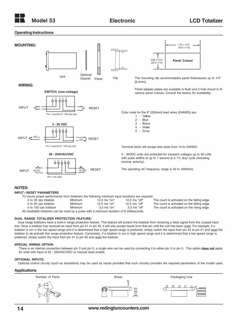
MOUNTING:
UnitOptionalGasket Panel Clip
WIRING:
The mounting clip accommodates panel thicknesses up to 1/4”[6.4mm].
Panel adapter plates are available in flush and 2 hole mount to fitvarious panel cutouts. Consult the factory for availability.
Color code for the 8” [203mm] lead wires (24AWG) are:1 - Yellow2 - Blue3 - Black4 - Violet5 - Gray
1.79 +/- 0.01 [45.5 +1/-0]
0.89 +/- 0.01 [22.6 +1/-0]
Panel Cutout
Pin 1 not used
RESETINPUT
20 - 250VAC/VDC
1 2 3 4 5
AC/DC AC/DC
RESETINPUT
Pin 1 used for 0 - 150 cps only
3 - 30 VDC
1 2 3 4 5
+DC+DC
Terminal block will accept wire sizes from 14 to 24AWG.
3 - 30VDC units are protected for transient voltages up to 50 voltswith pulse widths of up to 1 second at a 1% duty cycle (includingreverse polarity).
The operating AC frequency range is 40 to 400Hertz.
SWITCH (non-voltage)
RESETINPUT
Pin 1 used for 0 - 150 cps only
1 2 3 4 5
15www.redingtoncounters.com
Model 54 Electronic PCB Mount Totalizer
5400-0010 40/150 cps, switch, remote reset, w/battery
Description
Features Options
Specifications
Models Description
Dimensions
Applications
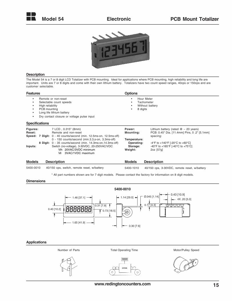
The Model 54 is a 7 or 8 digit LCD Totalizer with PCB mounting. Ideal for applications where PCB mounting, high reliability and long life areimportant. Units are 7 or 8 digits and come with their own lithium battery. Totalizers have two count speed ranges, 40cps or 150cps and arecustomer selectable.
• Remote or non-reset• Selectable count speeds• High reliability• PCB mounting• Long life lithium battery• Dry contact closure or voltage pulse input
• Hour Meter• Tachometer• Without battery• 8 digits
Figures: 7 LCD , 0.315" (8mm)Reset: Remote and non-resetSpeed: 7 Digit: 0 - 40 counts/second (min. 12.5ms-on, 12.5ms-off)
0 - 150 counts/second (min.3.3,s-on, 3.3ms-off)8 Digit: 0 - 35 counts/second (min. 14.3ms-on,14.3ms-off)
Inputs: Switch (no-voltage), 3-30VDC, 20-250VAC/VDCVih 20VAC/3VDC minimumVil 3VAC/1VDC maximum
Power: Lithium battery (rated @ ~ 20 years)Mounting: PCB: 0.45" Dia. [11.4mm] Pins, 0 .2" [5.1mm]
spacing:Temperature:
Operating: -4°F to +140°F [-20°C to +60°C]Storage: -40°F to +165°F [-40°C to +75°C]
Weight: 2oz [57g]
1.65 [41.9]0.30 [7.6]
1.14 [29.0]1.46 [37.1]
0.40 [10.2]0.31 [7.9]
0.73 [18.5]
Ø.045 [1.14]
0.17 [4.3]
0.43 [10.9]
4X .20 [5.0]
5400-0010
Number of Parts Total Operating Time Motor/Pulley Speed
5400-1010 40/150 cps, 3-30VDC, remote reset, w/battery
Models Description
* All part numbers shown are for 7 digit models. Please contact the factory for information on 8 digit models.
www.redingtoncounters.com
Model 94
16
Electronic LCD Totalizer
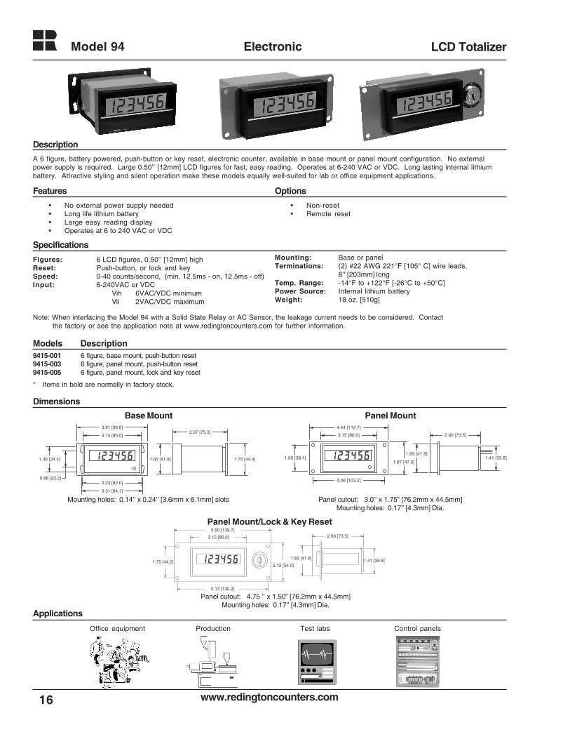
A 6 figure, battery powered, push-button or key reset, electronic counter, available in base mount or panel mount configuration. No externalpower supply is required. Large 0.50’’ [12mm] LCD figures for fast, easy reading. Operates at 6-240 VAC or VDC. Long lasting internal lithiumbattery. Attractive styling and silent operation make these models equally well-suited for lab or office equipment applications.
Figures: 6 LCD figures, 0.50’’ [12mm] highReset: Push-button, or lock and keySpeed: 0-40 counts/second, (min. 12.5ms - on, 12.5ms - off)Input: 6-240VAC or VDC
Vih 6VAC/VDC minimumVil 2VAC/VDC maximum
9415-001 6 figure, base mount, push-button reset9415-003 6 figure, panel mount, push-button reset9415-005 6 figure, panel mount, lock and key reset
Base Mount Panel Mount
Mounting holes: 0.14’’ x 0.24’’ [3.6mm x 6.1mm] slots Panel cutout: 3.0’’ x 1.75” [76.2mm x 44.5mm]Mounting holes: 0.17’’ [4.3mm] Dia.
Applications
Dimensions
Models Description
Description
Features Options
Specifications
• Non-reset• Remote reset
• No external power supply needed• Long life lithium battery• Large easy reading display• Operates at 6 to 240 VAC or VDC
Office equipment Production Test labs Control panels
Mounting: Base or panelTerminations: (2) #22 AWG 221°F [105° C] wire leads,
8’’ [203mm] longTemp. Range: -14°F to +122°F [-26°C to +50°C]Power Source: Internal lithium batteryWeight: 18 oz. [510g]
1.75 [44.4]
2.97 [75.3]
1.65 [41.9]
3.15 [80.0]
3.81 [96.8]
3.23 [82.0]
3.31 [84.1]
0.88 [22.2]
1.36 [34.4]1.87 [47.6]
1.50 [38.1]
4.06 [103.2]
3.15 [80.0]
4.44 [112.7]
1.65 [41.9]
2.90 [73.5]
1.41 [35.8]
Panel Mount/Lock & Key Reset
1.41 [35.8]
2.90 [73.5]3.15 [80.0]
5.50 [139.7]
2.12 [54.0]
1.65 [41.9]1.75 [44.5]
5.13 [130.2]
Panel cutout: 4.75 ’’ x 1.50” [76.2mm x 44.5mm]Mounting holes: 0.17’’ [4.3mm] Dia.
* Items in bold are normally in factory stock.
Note: When interfacing the Model 94 with a Solid State Relay or AC Sensor, the leakage current needs to be considered. Contactthe factory or see the application note at www.redingtoncounters.com for further information.
17www.redingtoncounters.com
Model E1 Electronic Tally Counter
Description
Features
Specifications
Models Description
Dimensions
ApplicationsFood portions
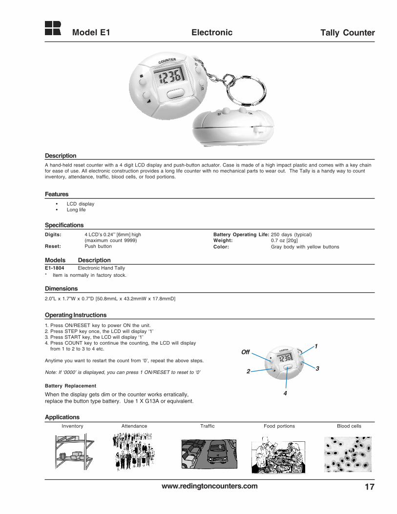
A hand-held reset counter with a 4 digit LCD display and push-button actuator. Case is made of a high impact plastic and comes with a key chainfor ease of use. All electronic construction provides a long life counter with no mechanical parts to wear out. The Tally is a handy way to countinventory, attendance, traffic, blood cells, or food portions.
Digits: 4 LCD’s 0.24’’ [6mm] high(maximum count 9999)
Reset: Push button
Battery Operating Life: 250 days (typical)Weight: 0.7 oz [20g]Color: Gray body with yellow buttons
Operating Instructions
1. Press ON/RESET key to power ON the unit.2. Press STEP key once, the LCD will display ‘1’3. Press START key, the LCD will display ‘1’4. Press COUNT key to continue the counting, the LCD will display
from 1 to 2 to 3 to 4 etc.
Anytime you want to restart the count from ‘0’, repeat the above steps.
Note: If ‘0000’ is displayed, you can press 1 ON/RESET to reset to ‘0’
When the display gets dim or the counter works erratically,replace the button type battery. Use 1 X G13A or equivalent.
Battery Replacement
Off
2
4
3
1
2.0”L x 1.7”W x 0.7”D [50.8mmL x 43.2mmW x 17.8mmD]
E1-1804 Electronic Hand Tally
* Item is normally in factory stock.
• LCD display• Long life
Inventory Attendance Traffic Blood cells
www.redingtoncounters.com
Model E2 & E3
18
Electronic LCD Tally Counter
Description
Specifications
Applications
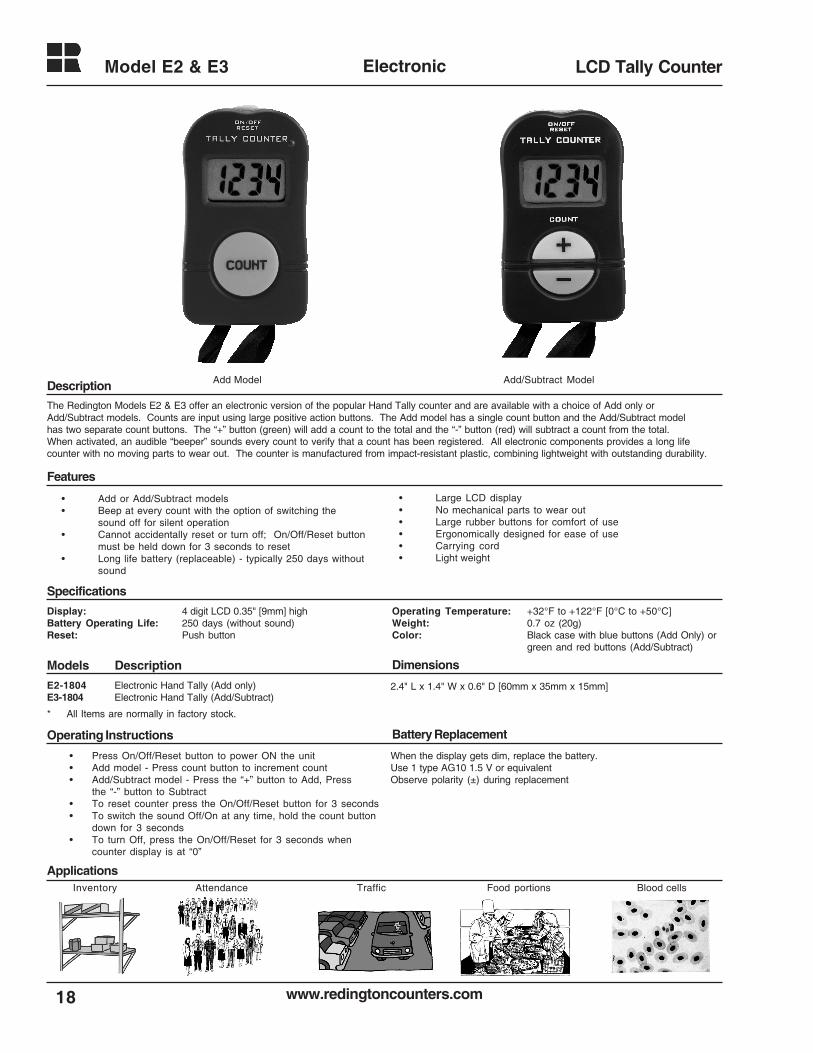
The Redington Models E2 & E3 offer an electronic version of the popular Hand Tally counter and are available with a choice of Add only orAdd/Subtract models. Counts are input using large positive action buttons. The Add model has a single count button and the Add/Subtract modelhas two separate count buttons. The “+” button (green) will add a count to the total and the “-” button (red) will subtract a count from the total.When activated, an audible “beeper” sounds every count to verify that a count has been registered. All electronic components provides a long lifecounter with no moving parts to wear out. The counter is manufactured from impact-resistant plastic, combining lightweight with outstanding durability.
Display: 4 digit LCD 0.35" [9mm] highBattery Operating Life: 250 days (without sound)Reset: Push button
E2-1804 Electronic Hand Tally (Add only)E3-1804 Electronic Hand Tally (Add/Subtract)
* All Items are normally in factory stock.
• Add or Add/Subtract models• Beep at every count with the option of switching the
sound off for silent operation• Cannot accidentally reset or turn off; On/Off/Reset button
must be held down for 3 seconds to reset• Long life battery (replaceable) - typically 250 days without
sound
• Large LCD display• No mechanical parts to wear out• Large rubber buttons for comfort of use• Ergonomically designed for ease of use• Carrying cord• Light weight
2.4" L x 1.4" W x 0.6" D [60mm x 35mm x 15mm]
• Press On/Off/Reset button to power ON the unit• Add model - Press count button to increment count• Add/Subtract model - Press the “+” button to Add, Press
the “-” button to Subtract• To reset counter press the On/Off/Reset button for 3 seconds• To switch the sound Off/On at any time, hold the count button
down for 3 seconds• To turn Off, press the On/Off/Reset for 3 seconds when
counter display is at “0”
When the display gets dim, replace the battery.Use 1 type AG10 1.5 V or equivalentObserve polarity (±) during replacement
Food portionsInventory Attendance Traffic Blood cells
Features
Models Description Dimensions
Operating Instructions Battery Replacement
Add Model Add/Subtract Model
Operating Temperature: +32°F to +122°F [0°C to +50°C]Weight: 0.7 oz (20g)Color: Black case with blue buttons (Add Only) or
green and red buttons (Add/Subtract)
19www.redingtoncounters.com
Model 10 Electromechanical Totalizer
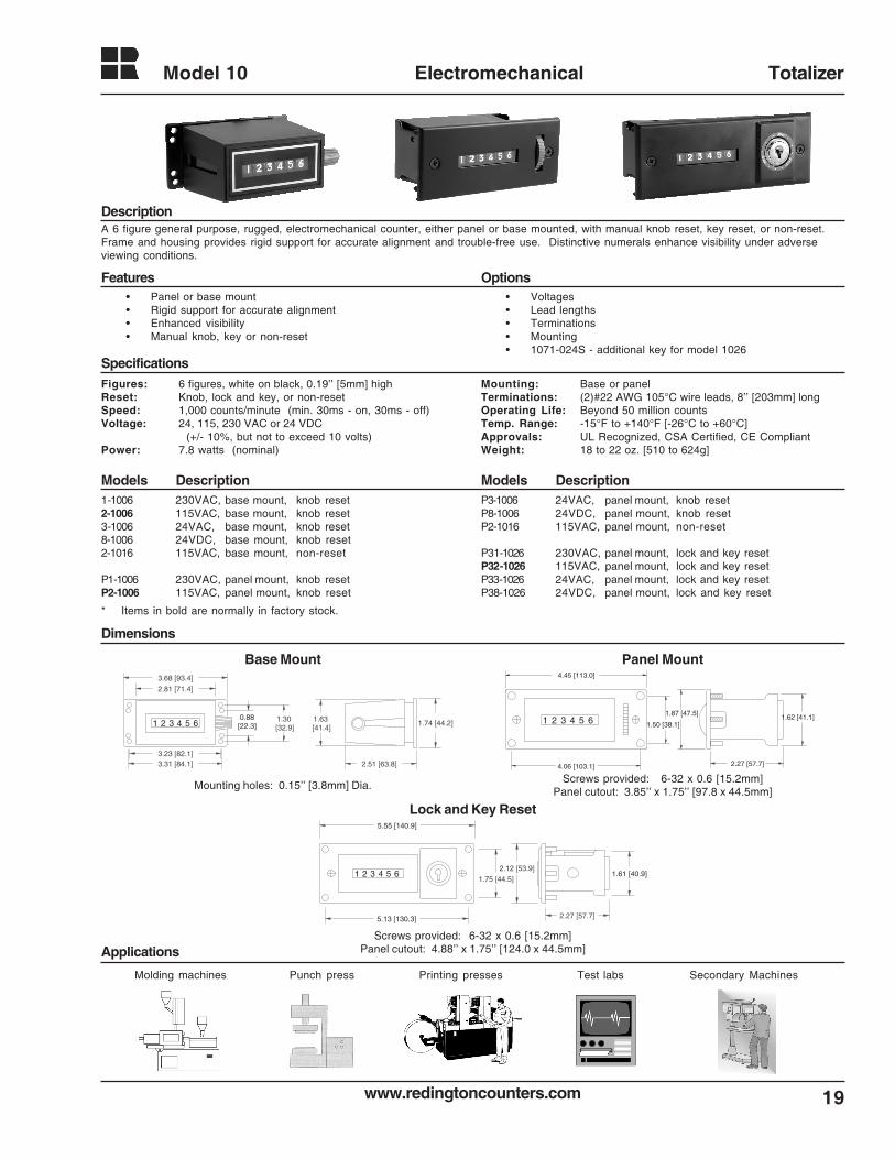
A 6 figure general purpose, rugged, electromechanical counter, either panel or base mounted, with manual knob reset, key reset, or non-reset.Frame and housing provides rigid support for accurate alignment and trouble-free use. Distinctive numerals enhance visibility under adverseviewing conditions.
Figures: 6 figures, white on black, 0.19’’ [5mm] highReset: Knob, lock and key, or non-resetSpeed: 1,000 counts/minute (min. 30ms - on, 30ms - off)Voltage: 24, 115, 230 VAC or 24 VDC
(+/- 10%, but not to exceed 10 volts)Power: 7.8 watts (nominal)
• Voltages• Lead lengths• Terminations• Mounting• 1071-024S - additional key for model 1026
Mounting: Base or panelTerminations: (2)#22 AWG 105°C wire leads, 8’’ [203mm] longOperating Life: Beyond 50 million countsTemp. Range: -15°F to +140°F [-26°C to +60°C]Approvals: UL Recognized, CSA Certified, CE CompliantWeight: 18 to 22 oz. [510 to 624g]
1-1006 230VAC, base mount, knob reset2-1006 115VAC, base mount, knob reset3-1006 24VAC, base mount, knob reset8-1006 24VDC, base mount, knob reset2-1016 115VAC, base mount, non-reset
P1-1006 230VAC, panel mount, knob resetP2-1006 115VAC, panel mount, knob reset
P3-1006 24VAC, panel mount, knob resetP8-1006 24VDC, panel mount, knob resetP2-1016 115VAC, panel mount, non-reset
P31-1026 230VAC, panel mount, lock and key resetP32-1026 115VAC, panel mount, lock and key resetP33-1026 24VAC, panel mount, lock and key resetP38-1026 24VDC, panel mount, lock and key reset
1 2 3 4 5 6 1.63 [41.4]
3.68 [93.4]
2.81 [71.4]
3.23 [82.1]3.31 [84.1] 2.51 [63.8]
1.74 [44.2]1.30 [32.9]
0.88[22.3]
4.06 [103.1]
1.62 [41.1]1 2 3 4 5 61.87 [47.5]
1.50 [38.1]
2.27 [57.7]
4.45 [113.0]
5.55 [140.9]
5.13 [130.3]
1.61 [40.9]1 2 3 4 5 62.12 [53.9]
1.75 [44.5]
2.27 [57.7]
Base Mount Panel Mount
Lock and Key Reset
Mounting holes: 0.15’’ [3.8mm] Dia.Screws provided: 6-32 x 0.6 [15.2mm]
Panel cutout: 3.85’’ x 1.75’’ [97.8 x 44.5mm]
Screws provided: 6-32 x 0.6 [15.2mm]Panel cutout: 4.88’’ x 1.75’’ [124.0 x 44.5mm]
Description
Features Options
Specifications
Models DescriptionModels Description
Dimensions
• Panel or base mount• Rigid support for accurate alignment• Enhanced visibility• Manual knob, key or non-reset
Applications
Test labsMolding machines Printing pressesPunch press Secondary Machines
* Items in bold are normally in factory stock.
www.redingtoncounters.com
Model 10
20
Electromechanical Totalizer
Applications
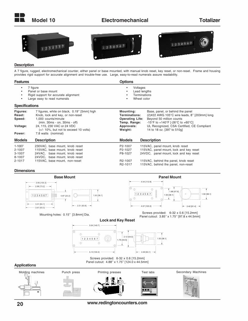
A 7 figure, rugged, electromechanical counter, either panel or base mounted, with manual knob reset, key reset, or non-reset. Frame and housingprovides rigid support for accurate alignment and trouble-free use. Large, easy-to-read numerals assure readability.
Figures: 7 figures, white on black, 0.19’’ [5mm] highReset: Knob, lock and key, or non-resetSpeed: 1,000 counts/minute
(min. 30ms - on, 30ms - off)Voltage: 24, 115, 230 VAC or 24 VDC
(+/- 10%, but not to exceed 10 volts)Power: 7.8 watts (nominal)
• Voltages• Lead lengths• Terminations• Wheel color
Mounting: Base, panel, or behind the panelTerminations: (2)#22 AWG 105°C wire leads, 8’’ [203mm] longOperating Life: Beyond 50 million countsTemp. Range: -15°F to +140°F [-26°C to +60°C]Approvals: UL Recognized, CSA Certified, CE CompliantWeight: 14 to 18 oz. [397 to 510g]
1-1007 230VAC, base mount, knob reset2-1007 115VAC, base mount, knob reset3-1007 24VAC, base mount, knob reset8-1007 24VDC, base mount, knob reset2-1017 115VAC, base mount, non-reset
P2-1007 115VAC, panel mount, knob resetP2-1027 115VAC, panel mount, lock and key resetP8-1027 24VDC, panel mount, lock and key reset
R2-1007 115VAC, behind the panel, knob resetR2-1017 115VAC, behind the panel, non-reset
1 2 3 4 5 6 7
3.67 [93.3]
3.95 [100.3]
2.88 [73.2]
0.87 [22.2]
3.31 [84.1]2.51 [63.8]
1.50 [38.1]
4.44 [112.9]
4.07 [103.3]
1.50 [38.1]
1.88 [47.6]1.50 [38.1]4321 5 6 7
2.42 [61.4]
5.54 [140.7]
5.13 [130.3]
1.50 [38.1]1.75 [44.5]
2.12 [54.0]4321 5 6 7
2.49 [63.1]
Base Mount Panel Mount
Lock and Key Reset
Mounting holes: 0.15’’ [3.8mm] Dia.Screws provided: 6-32 x 0.6 [15.2mm]
Panel cutout: 3.85’’ x 1.75’’ [97.8 x 44.5mm]
Screws provided: 6-32 x 0.6 [15.2mm]Panel cutout: 4.88’’ x 1.75’’ [124.0 x 44.5mm]
Description
Features Options
Specifications
Models DescriptionModels Description
Dimensions
• 7 figure• Panel or base mount• Rigid support for accurate alignment• Large easy to read numerals
Test labsMolding machines Printing pressesPunch press Secondary Machines
21www.redingtoncounters.com
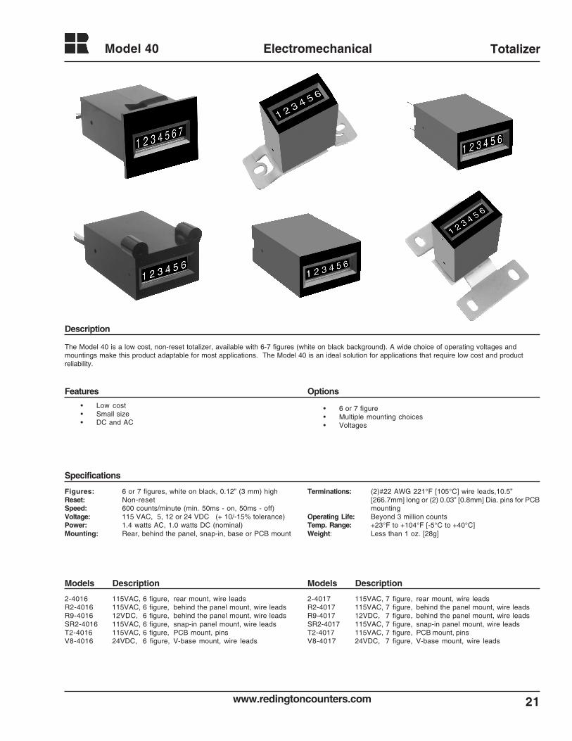
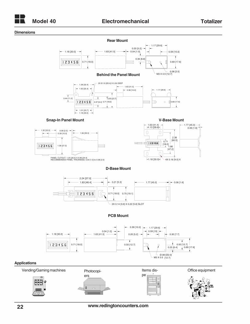
Model 40 Electromechanical Totalizer
• Low cost• Small size• DC and AC
• 6 or 7 figure• Multiple mounting choices• Voltages
Figures: 6 or 7 figures, white on black, 0.12” (3 mm) highReset: Non-resetSpeed: 600 counts/minute (min. 50ms - on, 50ms - off)Voltage: 115 VAC, 5, 12 or 24 VDC (+ 10/-15% tolerance)Power: 1.4 watts AC, 1.0 watts DC (nominal)Mounting: Rear, behind the panel, snap-in, base or PCB mount
Terminations: (2)#22 AWG 221°F [105°C] wire leads,10.5”[266.7mm] long or (2) 0.03” [0.8mm] Dia. pins for PCBmounting
Operating Life: Beyond 3 million countsTemp. Range: +23°F to +104°F [-5°C to +40°C]Weight: Less than 1 oz. [28g]
2-4016 115VAC, 6 figure, rear mount, wire leadsR2-4016 115VAC, 6 figure, behind the panel mount, wire leadsR9-4016 12VDC, 6 figure, behind the panel mount, wire leadsSR2-4016 115VAC, 6 figure, snap-in panel mount, wire leadsT2-4016 115VAC, 6 figure, PCB mount, pinsV8-4016 24VDC, 6 figure, V-base mount, wire leads
2-4017 115VAC, 7 figure, rear mount, wire leadsR2-4017 115VAC, 7 figure, behind the panel mount, wire leadsR9-4017 12VDC, 7 figure, behind the panel mount, wire leadsSR2-4017 115VAC, 7 figure, snap-in panel mount, wire leadsT2-4017 115VAC, 7 figure, PCB mount, pinsV8-4017 24VDC, 7 figure, V-base mount, wire leads
Description
Features Options
Specifications
Models DescriptionModels Description
The Model 40 is a low cost, non-reset totalizer, available with 6-7 figures (white on black background). A wide choice of operating voltages andmountings make this product adaptable for most applications. The Model 40 is an ideal solution for applications that require low cost and productreliability.
www.redingtoncounters.com
Model 40
22
Electromechanical Totalizer
1.17 [29.6]
0.69 [17.6]
1.18 [30.0]
0.71 [18.0]
1.63 [41.5] 0.04 [1.0]
0.08 [2.0]
0.59 [15.0]0.20 [5.2]
M3 X 0.5 [12.7]
0.35 [8.8]
0.71 [18.0]
1.63 [41.5]
1.17 [29.6]
0.69 [17.6]
0.44 [11.2]
1.28 [32.4]
1.00 [25.4]
1.18 [30.0]
0.93 [23.7]
2X Ø.10 [Ø2.6] X 0.35 DEEP
1.01 [25.7]
0.37 [9.4]
0.39 [10.0]
1.32 [33.5]
1.06 [27.0]
0.08 [2.0]1.56 [39.5]
PANEL CUTOUT: 1.20 [30.5] X 0.96 [24.4]
0.39 [10.0]
RECOMMENDED PANEL THICKNESS: 0.04 [1.0] to 0.08 [2.0]
2.24 [57.0]
1.83 [46.4] 0.21 [5.3]
0.71 [18.0] 0.75 [19.1]
1.77 [45.0] 0.06 [1.6]
2X 0.14 [3.6] X 0.22 [5.6] SLOT
1.18 [30.0]
0.71 [18.0]
1.63 [41.5]
0.50 [12.7]
1.17 [29.6]
0.69 [17.6]
0.20 [5.2]
Ø.08 [Ø2.0]
0.25 [6.4]0.50 [12.7]
0.30 [7.7]0.04 [1.0]
0.39 [10.0]
M3 X 0.5
0.59 [15]
[12.7]
1.77 [45.0]0.06 [1.6]
1.63 [41.4]1.13 [28.6]
1.18 [30.0]
0.71 [18.0]
1.86 [47.2]
2.38 [60.5]
4X 0.16 [4.0] X
Rear Mount
Behind the Panel Mount
Snap-In Panel Mount V-Base Mount
D-Base Mount
PCB Mount
Dimensions
Applications
Items dis-pensed
Office equipmentPhotocopi-ers
Vending/Gaming machines
23www.redingtoncounters.com
Model 44 Electromechanical Totalizer
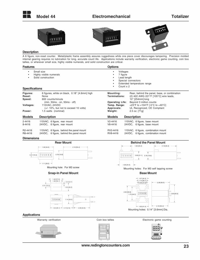
A 6 figure, non-reset counter. Metal/plastic frame assembly assures ruggedness while one piece cover discourages tampering. Precision moldedinternal gearing requires no lubrication for long, accurate count life. Applications include warranty verification, electronic game counting, coin boxtallies, or wherever small size, highly visible numerals, and solid construction are critical.
• Voltages• 7 figure• Lead length• Special connectors• Extended temperature range• Count x 2
Figures: 6 figures, white on black, 0.18’’ [4.6mm] highReset: NoneSpeed: 600 counts/minute
(min. 50ms - on, 50ms - off)Voltages: 115VAC, 24VDC
(+/- 10%, but not to exceed 10 volts)Power: 1.5 watts (nominal)
Mounting: Rear, behind the panel, base, or combinationTerminations: (2) #22 AWG 221°F [105°C] wire leads,
10’’ [254mm] longOperating Life: Beyond 3 million countsTemp. Range: +23°F to +104°F [-5°C to +40°C]Approvals: UL Recognized, CE CompliantWeight: 2.5 oz. [71g]
2-4416 115VAC, 6 figure, rear mount8-4416 24VDC, 6 figure, rear mount
R2-4416 115VAC, 6 figure, behind the panel mountR8-4416 24VDC, 6 figure, behind the panel mount
V2-4416 115VAC, 6 figure, base mountV8-4416 24VDC, 6 figure, base mount
RV2-4416 115VAC, 6 figure, combination mountRV8-4416 24VDC, 6 figure, combination mount
654321
2.18 [55.4]
0.78 [19.8]
1.36 [34.5]
0.41 [10.4]
1.11 [28.2]
654321
1.00 [25.4]
1.36 [34.5]
0.83 [21.1] 0.78 [19.8]
2.18 [55.4]
1.14 [29.0]
1.54 [39.1]
1.48 [37.6]1.38 [35.1]
1.03 [26.2]0.41 [10.4]
0.12 [3.1]
0.10 [2.5] 2.08 [52.8]
1 2 3 4 5 6
654321 2.36 [60.0]
1.63 [41.4]
1.75 [44.5]
2.00 [50.8]
0.98 [24.9]1.13 [28.7]1.27 [32.3]
2.18 [55.4]
2.38 [60.5]
Rear Mount Behind the Panel Mount
Snap-In Panel Mount Base Mount
Mounting hole: For M3 screw Mounting holes: For M3 self tapping screw
Mounting holes: 0.14’’ [3.6mm] Dia.
Description
Features Options
Specifications
Models DescriptionModels Description
Dimensions
• Small size• Highly visible numerals• Solid construction
Applications
Coin box tallies Electronic game countingWarranty verification
Model 48
24
Electromechanical
www.redingtoncounters.com
Totalizer
Applications
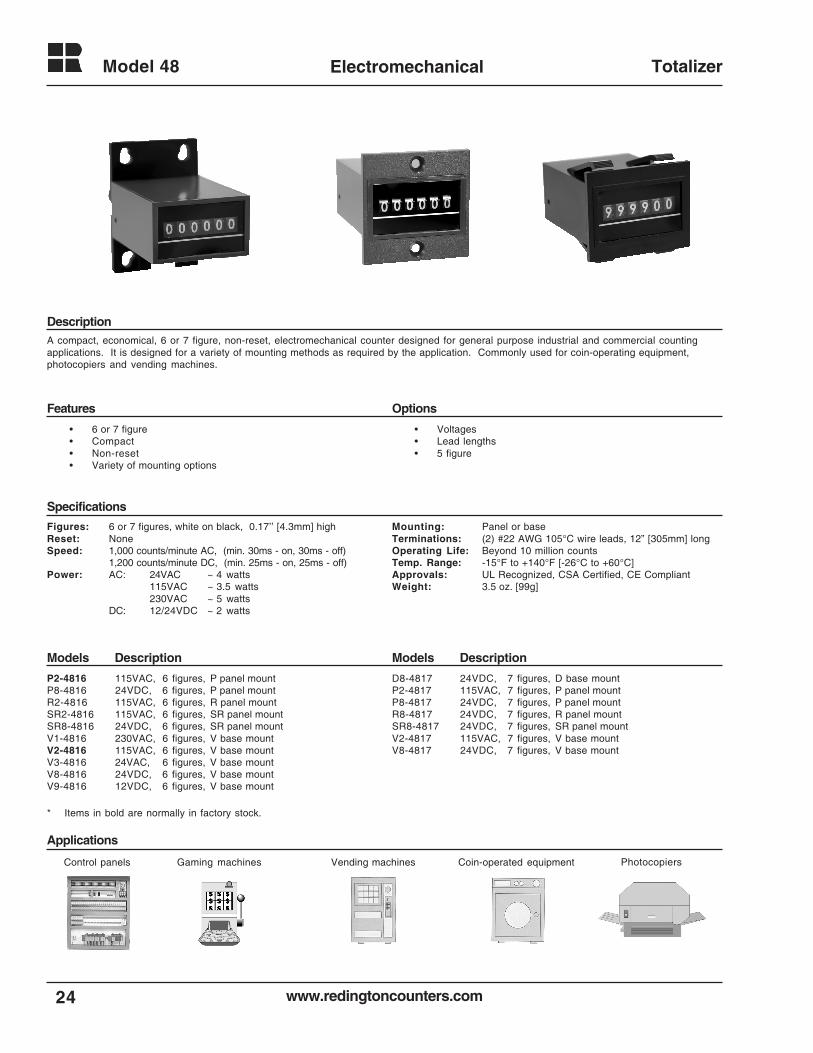
Control panels Gaming machines Vending machines PhotocopiersCoin-operated equipment
A compact, economical, 6 or 7 figure, non-reset, electromechanical counter designed for general purpose industrial and commercial countingapplications. It is designed for a variety of mounting methods as required by the application. Commonly used for coin-operating equipment,photocopiers and vending machines.
• Voltages• Lead lengths• 5 figure
Figures: 6 or 7 figures, white on black, 0.17’’ [4.3mm] highReset: NoneSpeed: 1,000 counts/minute AC, (min. 30ms - on, 30ms - off)
1,200 counts/minute DC, (min. 25ms - on, 25ms - off)Power: AC: 24VAC ~ 4 watts
115VAC ~ 3.5 watts230VAC ~ 5 watts
DC: 12/24VDC ~ 2 watts
Mounting: Panel or baseTerminations: (2) #22 AWG 105°C wire leads, 12” [305mm] longOperating Life: Beyond 10 million countsTemp. Range: -15°F to +140°F [-26°C to +60°C]Approvals: UL Recognized, CSA Certified, CE CompliantWeight: 3.5 oz. [99g]
P2-4816 115VAC, 6 figures, P panel mountP8-4816 24VDC, 6 figures, P panel mountR2-4816 115VAC, 6 figures, R panel mountSR2-4816 115VAC, 6 figures, SR panel mountSR8-4816 24VDC, 6 figures, SR panel mountV1-4816 230VAC, 6 figures, V base mountV2-4816 115VAC, 6 figures, V base mountV3-4816 24VAC, 6 figures, V base mountV8-4816 24VDC, 6 figures, V base mountV9-4816 12VDC, 6 figures, V base mount
D8-4817 24VDC, 7 figures, D base mountP2-4817 115VAC, 7 figures, P panel mountP8-4817 24VDC, 7 figures, P panel mountR8-4817 24VDC, 7 figures, R panel mountSR8-4817 24VDC, 7 figures, SR panel mountV2-4817 115VAC, 7 figures, V base mountV8-4817 24VDC, 7 figures, V base mount
Description
Features Options
Specifications
Models DescriptionModels Description
• 6 or 7 figure• Compact• Non-reset• Variety of mounting options
* Items in bold are normally in factory stock.
25www.redingtoncounters.com
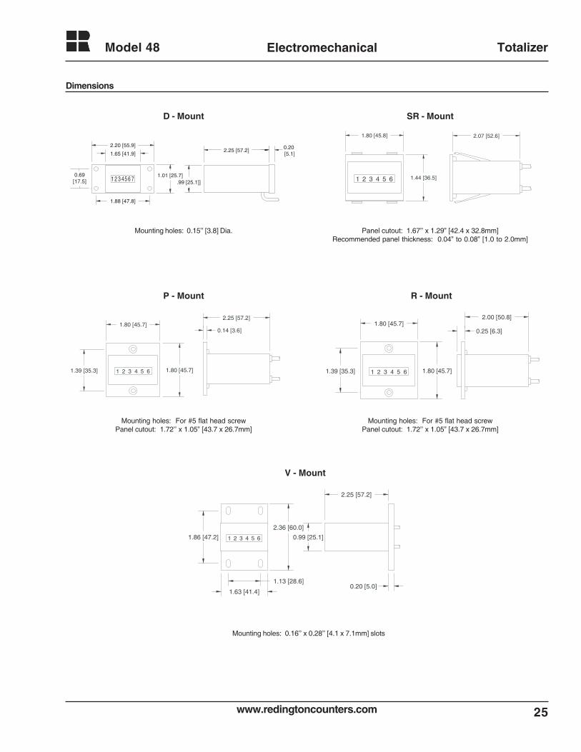
Model 48 Electromechanical Totalizer
1 2 3 4 5 6
2.25 [57.2]
0.99 [25.1]
2.36 [60.0]
1.86 [47.2]
1.13 [28.6]
1.63 [41.4]0.20 [5.0]
P - Mount R - Mount
V - Mount
Mounting holes: For #5 flat head screwPanel cutout: 1.72’’ x 1.05” [43.7 x 26.7mm]
Mounting holes: For #5 flat head screwPanel cutout: 1.72’’ x 1.05” [43.7 x 26.7mm]
Mounting holes: 0.16’’ x 0.28’’ [4.1 x 7.1mm] slots
1 2 3 4 5 6 1.44 [36.5]
1.80 [45.8] 2.07 [52.6]
Mounting holes: 0.15’’ [3.8] Dia. Panel cutout: 1.67’’ x 1.29” [42.4 x 32.8mm]Recommended panel thickness: 0.04” to 0.08” [1.0 to 2.0mm]
D - Mount SR - Mount
Dimensions
1 2 3 45 6
2.25 [57.2]
.99 [25.1]]71.01 [25.7]
1.65 [41.9]
2.20 [55.9]
1.88 [47.8]
0.20 [5.1]
0.69[17.5]
1 2 3 4 5 61.39 [35.3] 1.80 [45.7]
1.80 [45.7]0.14 [3.6]
2.25 [57.2]1.80 [45.7]
1.80 [45.7]1 2 3 4 5 61.39 [35.3]
0.25 [6.3]
2.00 [50.8]
www.redingtoncounters.com
Model 49
26
Electromechanical Totalizer
• Voltages• Extended temperatures• 4 or 6 figure
Description
Features Options
Specifications
Models DescriptionModels Description
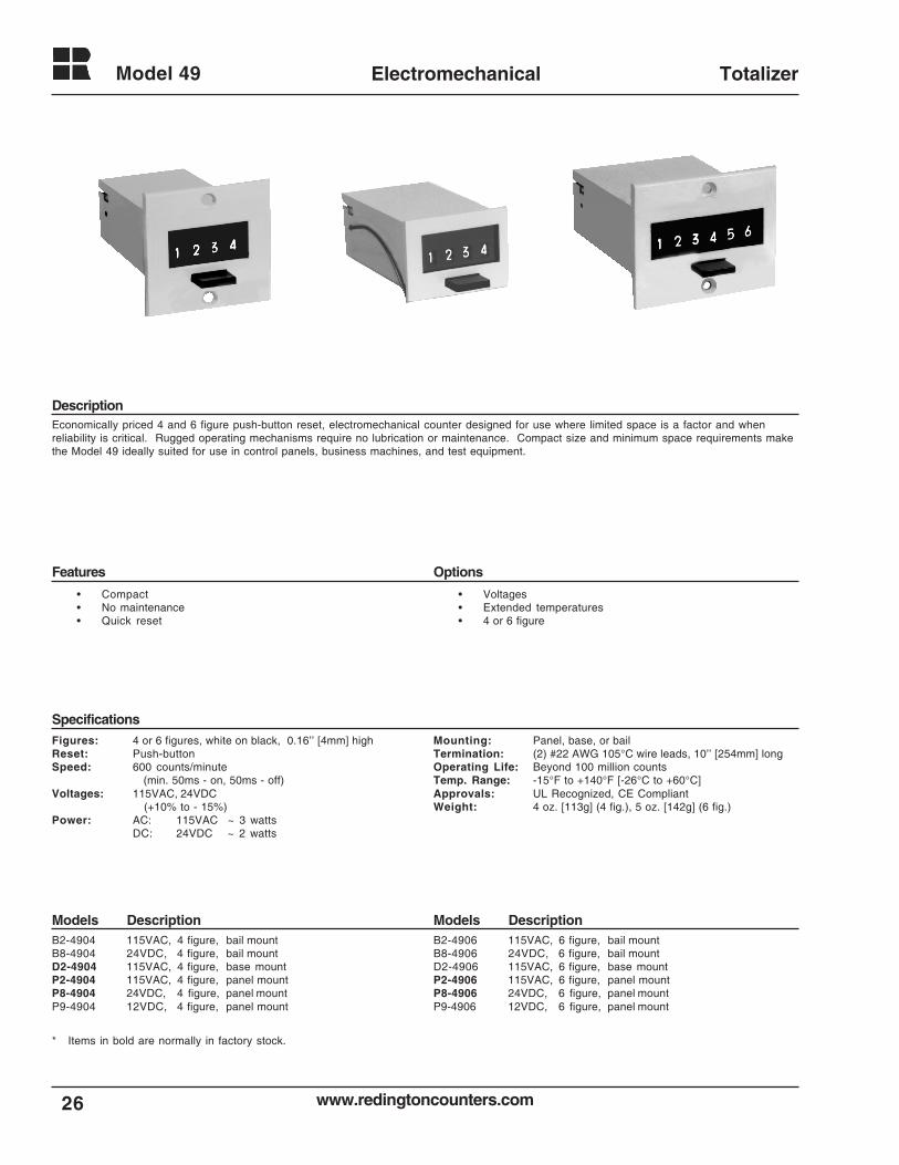
Economically priced 4 and 6 figure push-button reset, electromechanical counter designed for use where limited space is a factor and whenreliability is critical. Rugged operating mechanisms require no lubrication or maintenance. Compact size and minimum space requirements makethe Model 49 ideally suited for use in control panels, business machines, and test equipment.
Figures: 4 or 6 figures, white on black, 0.16’’ [4mm] highReset: Push-buttonSpeed: 600 counts/minute
(min. 50ms - on, 50ms - off)Voltages: 115VAC, 24VDC
(+10% to - 15%)Power: AC: 115VAC ~ 3 watts
DC: 24VDC ~ 2 watts
Mounting: Panel, base, or bailTermination: (2) #22 AWG 105°C wire leads, 10’’ [254mm] longOperating Life: Beyond 100 million countsTemp. Range: -15°F to +140°F [-26°C to +60°C]Approvals: UL Recognized, CE CompliantWeight: 4 oz. [113g] (4 fig.), 5 oz. [142g] (6 fig.)
B2-4904 115VAC, 4 figure, bail mountB8-4904 24VDC, 4 figure, bail mountD2-4904 115VAC, 4 figure, base mountP2-4904 115VAC, 4 figure, panel mountP8-4904 24VDC, 4 figure, panel mountP9-4904 12VDC, 4 figure, panel mount
B2-4906 115VAC, 6 figure, bail mountB8-4906 24VDC, 6 figure, bail mountD2-4906 115VAC, 6 figure, base mountP2-4906 115VAC, 6 figure, panel mountP8-4906 24VDC, 6 figure, panel mountP9-4906 12VDC, 6 figure, panel mount
• Compact• No maintenance• Quick reset
* Items in bold are normally in factory stock.
27www.redingtoncounters.com
Model 49 Electromechanical Totalizer
Applications
Control Panels Business Machines Medical devicesTest Equipment
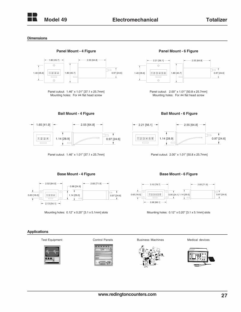
Dimensions
2.55 [64.8]1.65 [41.9]
1.14 [28.9] 0.97 [24.6]321 4
Panel cutout: 1.46’’ x 1.01” [37.1 x 25.7mm]
Bail Mount - 4 Figure
31 6
2.83 [71.9]3.10 [78.7]
1.14 [29.0] 0.97 [24.6]2 4 5 0.95 [24.1]0.63 [16.0]
2.68 [68.1]
Mounting holes: 0.12’’ x 0.20’’ [3.1 x 5.1mm] slots
Base Mount - 6 Figure
31 6
2.55 [64.8]2.21 [56.1]
1.14 [28.9] 0.97 [24.6]2 4 5
Bail Mount - 6 Figure
Panel cutout: 2.00’’ x 1.01” [50.8 x 25.7mm]
2.55 [64.8]1.80 [45.7]
1.80 [45.7] 0.97 [24.6]1.40 [35.6] 321 4
Panel Mount - 4 Figure
Panel cutout: 1.46’’ x 1.01” [37.1 x 25.7mm]Mounting holes: For #4 flat head screw
0.97 [24.6]321 4
0.98 [24.9]
2.13 [54.1]
2.52 [64.0] 2.83 [71.9]
1.14 [29.0]0.63 [16.0]
Base Mount - 4 Figure
Mounting holes: 0.12’’ x 0.20’’ [3.1 x 5.1mm] slots
Panel Mount - 6 Figure
Panel cutout: 2.00’’ x 1.01” [50.8 x 25.7mm]Mounting holes: For #4 flat head screw
2.55 [64.8]2.21 [56.1]
1.80 [45.7] 0.97 [24.6]1.40 [35.6] 321 64 5
www.redingtoncounters.com28
Model 128 Electromechanical Totalizer
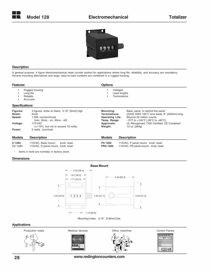
A general purpose, 4 figure electromechanical reset counter perfect for applications where long life, reliability, and accuracy are mandatory.Several mounting alternatives and large, easy-to-read numbers are combined in a rugged housing.
Figures: 4 figures, white on black, 0.19’’ [5mm] highReset: KnobSpeed: 1,000 counts/minute
(min. 30ms - on, 30ms - off)Voltage: 115 VAC
(+/-10%, but not to exceed 10 volts)Power: 5 watts (nominal)
• Voltages• Lead lengths• Terminations
Mounting: Base, panel, or behind the panelTerminations: (2)#22 AWG 105°C wire leads, 8’’ [203mm] longOperating Life: Beyond 50 million countsTemp. Range: -15°F to +140°F [-26°C to +60°C]Approvals: UL Recognized, CSA Certified, CE CompliantWeight: 10 oz. [284g]
2-1284 115VAC, Base mount, knob resetD2-1284 115VAC, D panel mount, knob reset
P2-1284 115VAC, P panel mount, knob resetPR2-1284 115VAC, PR panel mount, knob reset
Base Mount
Mounting holes: 0.15’’ [3.8mm] Dia.
• Rugged housing• Long life• Reliable• Accurate
Applications
Dimensions
Models DescriptionModels Description
Specifications
Features Options
Description
21 3 4 2.25 [57.2]1.94 [49.2]
1.13 [28.6]
1.71 [43.4]
1.81 [46.0]
2.30 [58.4]
1.64 [41.7]
2.49 [63.3]
Medical devices Office machinesProduction totals Control Panels
* Items in bold are normally in factory stock.
29www.redingtoncounters.com
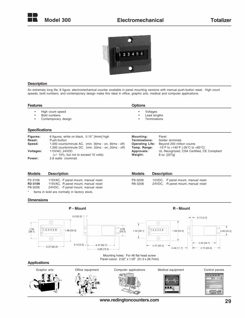
Model 300 Electromechanical Totalizer
An extremely long life, 6 figure, electromechanical counter available in panel mounting versions with manual push-button reset. High countspeeds, bold numbers, and contemporary design make this ideal in office, graphic arts, medical and computer applications.
• Voltages• Lead lengths• Terminations
Figures: 6 figures, white on black, 0.15’’ [4mm] highReset: Push-buttonSpeed: 1,000 counts/minute AC, (min. 30ms - on, 30ms - off)
1,500 counts/minute DC, (min. 20ms - on, 20ms - off)Voltages: 115VAC, 24VDC
(+/- 10%, but not to exceed 10 volts)Power: 2.8 watts (nominal)
Mounting: PanelTerminations: Solder terminalsOperating Life: Beyond 200 million countsTemp. Range: -15°F to +140°F [-26°C to +60°C]Approvals: UL Recognized, CSA Certified, CE CompliantWeight: 8 oz. [227g]
P2-3106 115VAC, P panel mount, manual resetR2-3106 115VAC, R panel mount, manual resetP8-3206 24VDC, P panel mount, manual reset
P9-3206 12VDC, P panel mount, manual resetR8-3206 24VDC, R panel mount, manual reset
1 2 3 4 5 6
2.37 [60.2]
1.98 [50.3]1.50 [38.1]
2.35 [59.7]
2.75 [69.9]
0.13 [3.3]
0.99 [25.2]
0.46 [11.7]
P - Mount R - Mount
Mounting holes: For #8 flat head screwPanel cutout: 2.02’’ x 1.05” [51.3 x 26.7mm]
Description
Features Options
Specifications
Models DescriptionModels Description
Dimensions
Applications
• High count speed• Bold numbers• Contemporary design
1 2 3 4 5 6
2.37 [60.2]
1.98 [50.3]1.50 [38.1]
0.99 [25.2]
2.47 [62.7]0.13 [3.3]
2.88 [73.2]
0.21[5.3]
Office equipmentGraphic arts Medical equipmentComputer applications Control panels
* Items in bold are normally in factory stock.
www.redingtoncounters.com
Model 08
30
Mechanical Rotary Counter
Description
Features Options
Specifications
Models DescriptionModels Description
Dimensions
Applications
Linear measuring Machine revolutions Positioning
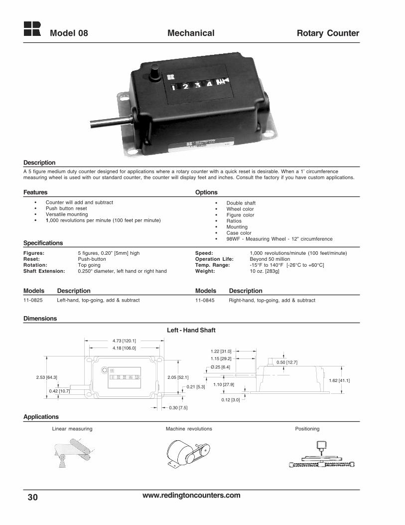
A 5 figure medium duty counter designed for applications where a rotary counter with a quick reset is desirable. When a 1’ circumferencemeasuring wheel is used with our standard counter, the counter will display feet and inches. Consult the factory if you have custom applications.
• Counter will add and subtract• Push button reset• Versatile mounting• 1,000 revolutions per minute (100 feet per minute)
• Double shaft• Wheel color• Figure color• Ratios• Mounting• Case color• 98WF - Measuring Wheel - 12” circumference
Figures: 5 figures, 0.20” [5mm] highReset: Push-buttonRotation: Top goingShaft Extension: 0.250“ diameter, left hand or right hand
Speed: 1,000 revolutions/minute (100 feet/minute)Operation Life: Beyond 50 millionTemp. Range: -15°F to 140°F [-26°C to +60°C]Weight: 10 oz. [283g]
11-0825 Left-hand, top-going, add & subtract 11-0845 Right-hand, top-going, add & subtract
4.18 [106.0]
4.73 [120.1]
2.05 [52.1]
0.42 [10.7]
2.53 [64.3]
0.21 [5.3]
0.30 [7.5]
0.12 [3.0]
Ø.25 [6.4]
1.15 [29.2]
1.22 [31.0]
0.50 [12.7]
1.62 [41.1]1.10 [27.9]
Left - Hand Shaft
31www.redingtoncounters.com
Model 14 Mechanical Small Case Totalizers
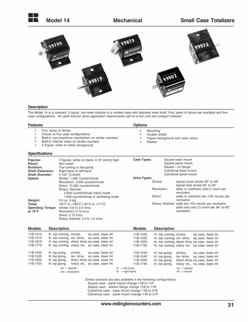
• Four types of drives• Choice of five case configurations• Built-in non-overthrow mechanism on stroke counters• Built-in internal stops on stroke counters• 5 Figure: white on black background
• Mounting• Double shafts• Figure background and case colors• Sealed
The Model 14 is a compact, 5 figure, non-reset totalizer in a molded case with stainless steel shaft. Four types of drives are available and fivecase configurations. An ideal solution when application requirements call for a low cost and compact totalizer.
Figures: 5 figures, white on black, 0.16” [4mm] highReset: Non-resetRotation: Top-coming or top-goingShaft Extension: Right-hand or left-handShaft Diameter: 0.125” [3.2mm]Speed: Stroke: 1,000 counts/minute
Revolution: 3,000 counts/minuteDirect: 15,000 counts/minuteRotary Ratchet: 3,000 counts/minute rotary mode 1,500 counts/minute in oscillating mode
Weight: 0.5 oz. [14g]Temp: -40°F to +160°F [-40°C to +71°C]Operating Torque: Stroke; 0.8 to 2.0 in/ozat 75°F Revolution; 0.15 in/oz
Direct; 0.15 in/ozRotary Ratchet; 0.3 to 1.0 in/oz
Case Types: Square base mountSquare panel mountSquare - no flangeCylindrical base mountCylindrical panel mount
Drive Types:Stroke: typical count stroke 39° to 48°
typical total stroke 50° to 52°Revolution: adds or subtracts one(1) count per
revolution.Direct: adds or subtracts ten (10) counts per
revolutionRotary Ratchet: adds ten (10) counts per revolution
adds only one (1) count per 36° to 60°oscillation.
11B-1415 lh, top coming, stroke, sq case, base mt11B-1515 lh, top coming, rev. drive, sq case, base mt11B-1615 lh, top coming, direct drive, sq case, base mt11B-1715 lh, top coming, rotary rat., sq case, base mt
11B-1425 lh, top going, stroke, sq case, base mt11B-1525 lh, top going, rev. drive, sq case, base mt11B-1625 lh, top going, direct drive, sq case, base mt11B-1725 lh, top going, rotary rat., sq case, base mt
11B-1435 rh, top coming, stroke, sq case, base mt11B-1535 rh, top coming, rev. drive, sq case, base mt11B-1635 rh, top coming, direct drive, sq case, base mt11B-1735 rh, top coming, rotary rat., sq case, base mt
11B-1445 rh, top going, stroke, sq case, base mt11B-1545 rh, top going, rev drive, sq case, base mt11B-1645 rh, top going, direct drive, sq case, base mt11B-1745 rh, top going, rotary rat., sq case, base mt
rat = ratchetrev = revolution
sq = squaremt = mount
lh = left handrh = right hand
Similar products are also available in the following configurations:Square case - panel mount change 11B to 11PSquare case - without flange change 11B to 11NCylindrical case - base mount change 11B to 21BCylindrical case - panel mount change 11B to 21P
Description
Features Options
Specifications
Models DescriptionModels Description
www.redingtoncounters.com
Model 14
32
Mechanical Small Case Totalizers
0.88 [22.4]0.43[10.9]
0.35[8.9]
1.06[26.9]
0.125 [3.2]
0.80[20.3] 0.45
[11.4]
0.81 [20.6]
0.026 [0.7] X 0.020D [0.5]
SLOT
1.36[34.5]
0.11 [2.8]
0.43[10.9]
0.03[0.8]
2X 0.13 [3.3]
0.88 [22.4]0.43
[10.9]
0.35[8.9]
1.06[26.9]
0.08[2.0]
0.62[15.8]
1.36[34.5]
0.125[3.2]
0.45[11.4]
2x 0.13 [3.3]
0.02[0.5]
0.43[10.9]
0.81 [20.6]
0.11 [2.8]
0.80[20.3]
0.026 [0.7] x 0.020D [0.5]
SLOT
0.80[20.3]
0.88 [22.4] 0.35[8.9]
0.08 [2.0] 0.62 [15.8]
0.125[3.2]
0.45[11.4]
0.80 [20.3]
0.40[10.2]
0.03[7.6] 0.43
[10.9]
0.026 [0.7] X 0.020D [0.5] SLOT
0.88 [22.4]0.41
[10.9]
0.35[8.9]
0.08[2.0]
0.62 [15.8]2x 0.13 [3.3]
0.125[3.2]
0.80[20.3]
0.38[9.7]
0.84 [21.3]0.41[10.4] 0.10
[2.5]
1.26[32.0]
0.63[16.0]
0.026 [0.7] X 0.020D [0.5] SLOT
0.129[3.3]
0.095[2.4]
0.22 [5.6]
0.437 [11.1] 0.65[16.5]
0.25[6.4]
0.31[7.9]
0.057 [1.5]
0.129[3.3]
0.095[2.4]
0.437[11.1]
0.22 [5.6]
1.0 [25.4]
1.12[28.5]
0.25[6.4]
0.31 [7.9]
0.057[1.5]
0.94[23.9]
0.88 [22.4]
0.41[10.4]
0.35[8.9]
0.08 [2.0] 0.62 [15.8]2X 0.13 [3.3]
0.125[3.2]
1.27[32.3]
0.38[9.7]
0.43[10.9]
0.80 [20.3]
0.026 [0.7] X 0.020D [0.5] SLOT0.10 [2.5]
0.07 [1.8]
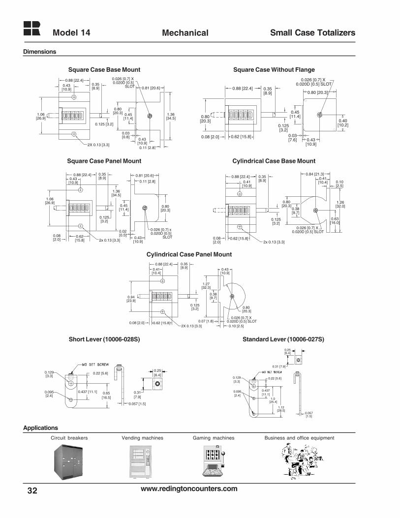
Square Case Base Mount Square Case Without Flange
Square Case Panel Mount Cylindrical Case Base Mount
Short Lever (10006-028S) Standard Lever (10006-027S)
Cylindrical Case Panel Mount
Applications
Dimensions
Vending machinesCircuit breakers Gaming machines Business and office equipment
33www.redingtoncounters.com
Model 18 Mechanical Tally Counter
Description
Features Options
Specifications
Models DescriptionModels Description
Dimensions
Applications
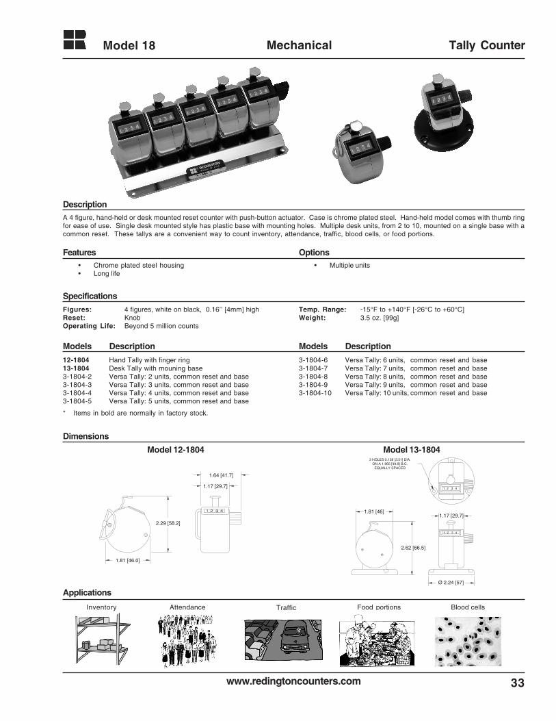
A 4 figure, hand-held or desk mounted reset counter with push-button actuator. Case is chrome plated steel. Hand-held model comes with thumb ringfor ease of use. Single desk mounted style has plastic base with mounting holes. Multiple desk units, from 2 to 10, mounted on a single base with acommon reset. These tallys are a convenient way to count inventory, attendance, traffic, blood cells, or food portions.
Figures: 4 figures, white on black, 0.16’’ [4mm] highReset: KnobOperating Life: Beyond 5 million counts
12-1804 Hand Tally with finger ring13-1804 Desk Tally with mouning base3-1804-2 Versa Tally: 2 units, common reset and base3-1804-3 Versa Tally: 3 units, common reset and base3-1804-4 Versa Tally: 4 units, common reset and base3-1804-5 Versa Tally: 5 units, common reset and base
Model 12-1804
Temp. Range: -15°F to +140°F [-26°C to +60°C]Weight: 3.5 oz. [99g]
3-1804-6 Versa Tally: 6 units, common reset and base3-1804-7 Versa Tally: 7 units, common reset and base3-1804-8 Versa Tally: 8 units, common reset and base3-1804-9 Versa Tally: 9 units, common reset and base3-1804-10 Versa Tally: 10 units, common reset and base
1.17 [29.7]
1.64 [41.7]
1.81 [46.0]
1 32 4
2.29 [58.2]
1 2 3 4
1 2 3 4
3 HOLES 0.138 [3.51] DIA. ON A 1.965 [49.9] B.C.
EQUALLY SPACED
2.62 [66.5]
1.81 [46]
Ø 2.24 [57]
1.17 [29.7]
Model 13-1804
• Chrome plated steel housing• Long life
• Multiple units
Food portionsInventory Attendance Traffic Blood cells
* Items in bold are normally in factory stock.
www.redingtoncounters.com
Model 19
34
Mechanical Modular Tally Counter
Description
Features Options
Specifications
Models Description
Dimensions
Applications
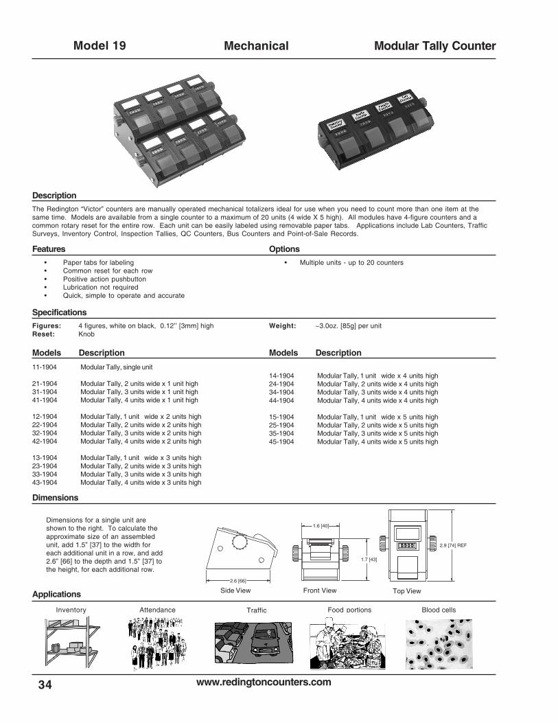
The Redington “Victor” counters are manually operated mechanical totalizers ideal for use when you need to count more than one item at thesame time. Models are available from a single counter to a maximum of 20 units (4 wide X 5 high). All modules have 4-figure counters and acommon rotary reset for the entire row. Each unit can be easily labeled using removable paper tabs. Applications include Lab Counters, TrafficSurveys, Inventory Control, Inspection Tallies, QC Counters, Bus Counters and Point-of-Sale Records.
Figures: 4 figures, white on black, 0.12’’ [3mm] highReset: Knob
11-1904 Modular Tally, single unit
21-1904 Modular Tally, 2 units wide x 1 unit high31-1904 Modular Tally, 3 units wide x 1 unit high41-1904 Modular Tally, 4 units wide x 1 unit high
12-1904 Modular Tally, 1 unit wide x 2 units high22-1904 Modular Tally, 2 units wide x 2 units high32-1904 Modular Tally, 3 units wide x 2 units high42-1904 Modular Tally, 4 units wide x 2 units high
13-1904 Modular Tally, 1 unit wide x 3 units high23-1904 Modular Tally, 2 units wide x 3 units high33-1904 Modular Tally, 3 units wide x 3 units high43-1904 Modular Tally, 4 units wide x 3 units high
Weight: ~3.0oz. [85g] per unit
• Paper tabs for labeling• Common reset for each row• Positive action pushbutton• Lubrication not required• Quick, simple to operate and accurate
• Multiple units - up to 20 counters
Dimensions for a single unit areshown to the right. To calculate theapproximate size of an assembledunit, add 1.5” [37] to the width foreach additional unit in a row, and add2.6” [66] to the depth and 1.5” [37] tothe height, for each additional row.
14-1904 Modular Tally, 1 unit wide x 4 units high24-1904 Modular Tally, 2 units wide x 4 units high34-1904 Modular Tally, 3 units wide x 4 units high44-1904 Modular Tally, 4 units wide x 4 units high
15-1904 Modular Tally, 1 unit wide x 5 units high25-1904 Modular Tally, 2 units wide x 5 units high35-1904 Modular Tally, 3 units wide x 5 units high45-1904 Modular Tally, 4 units wide x 5 units high
Models Description
Side View Top ViewFront View
1.7 [43]
2.9 [74] REF
1.6 [40]
2.6 [66]
Food portionsInventory Attendance Traffic Blood cells
35www.redingtoncounters.com
Model 20 Mechanical Stroke Counter
Description
Features Options
Specifications
Models DescriptionModels Description
Dimensions
Applications
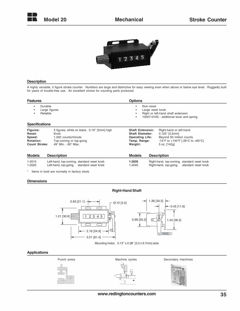
A highly versatile, 5 figure stroke counter. Numbers are large and distinctive for easy viewing even when above or below eye level. Ruggedly builtfor years of trouble-free use. An excellent choice for counting parts produced.
Figures: 5 figures, white on black, 0.19’’ [5mm] highReset: KnobSpeed: 1,000 counts/minuteRotation: Top-coming or top-goingCount Stroke: 49° Min. - 60° Max.
Shaft Extension: Right-hand or left-handShaft Diameter: 0.125’’ [3.2mm]Operating Life: Beyond 50 million countsTemp. Range: -15°F to +140°F [-26°C to +60°C]Weight: 5 oz. [142g]
• Non-reset• Large reset knob• Right or left-hand shaft extension• 10007-010S - additional lever and spring
1-2015 Left-hand, top-coming, standard reset knob1-2025 Left-hand, top-going, standard reset knob
1-2035 Right-hand, top-coming, standard reset knob1-2045 Right-hand, top-going, standard reset knob
1.44 [36.5]
1.36 [34.5]
0.99 [25.2]
0.45 [11.6]
2.16 [54.9]
321 4 5
3.21 [81.4]
0.83 [21.1]
1.21 [30.6]
Ø.12 [3.2]
Right-Hand Shaft
Mounting holes: 0.13’’ x 0.38’’ [3.3 x 9.7mm] slots
• Durable• Large figures• Reliable
Machine cycles Secondary machinesPunch press
* Items in bold are normally in factory stock.
www.redingtoncounters.com
Model 22
36
Mechanical Rotary Counter
Description
Features Options
Specifications
Models DescriptionModels Description
Dimensions
Applications
2.16 [54.9]
3.13 [79.5]
1.44 [36.5]321 4 5
1.38 [35.1]
0.99 [25.2]
0.83 [21.1]
1.20 [30.5]
0.47 [12.1]
Ø.12 [Ø3.2]
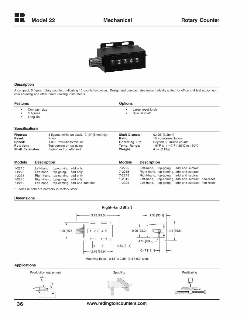
A compact, 5 figure, rotary counter, indicating 10 counts/revolution. Design and compact size make it ideally suited for office and test equipment,coin counting and other direct reading instruments.
Figures: 5 figures, white on black, 0.19’’ [5mm] highReset: KnobSpeed: 1,000 revolutions/minuteRotation: Top-coming or top-goingShaft Extension: Right-hand or left-hand
• Large reset knob• Special shaft
Shaft Diameter: 0.125’’ [3.2mm]Ratio: 10 counts/revolutionOperating Life: Beyond 50 million countsTemp. Range: -15°F to +140°F [-26°C to +60°C]Weight: 4 oz. [113g]
1-2215 Left-hand, top-coming, add only1-2225 Left-hand, top-going, add only1-2235 Right-hand, top-coming, add only1-2245 Right-hand, top-going, add only7-2215 Left-hand, top-coming, add and subtract
7-2225 Left-hand, top-going, add and subtract7-2235 Right-hand, top-coming, add and subtract7-2245 Right-hand, top-going, add and subtract1-2315 Left-hand, top-coming, add and subtract, non-reset1-2325 Left-hand, top-going, add and subtract, non-reset
Mounting holes: 0.13’’ x 0.38’’ [3.3 x 9.7] slots
Right-Hand Shaft
• Compact size• 5 figures• Long life
Production equipment PositioningSpooling
* Items in bold are normally in factory stock.
37www.redingtoncounters.com
Model 27 Mechanical Stroke Counter
Description
Features Options
Specifications
Models DescriptionModels Description
Dimensions
Applications
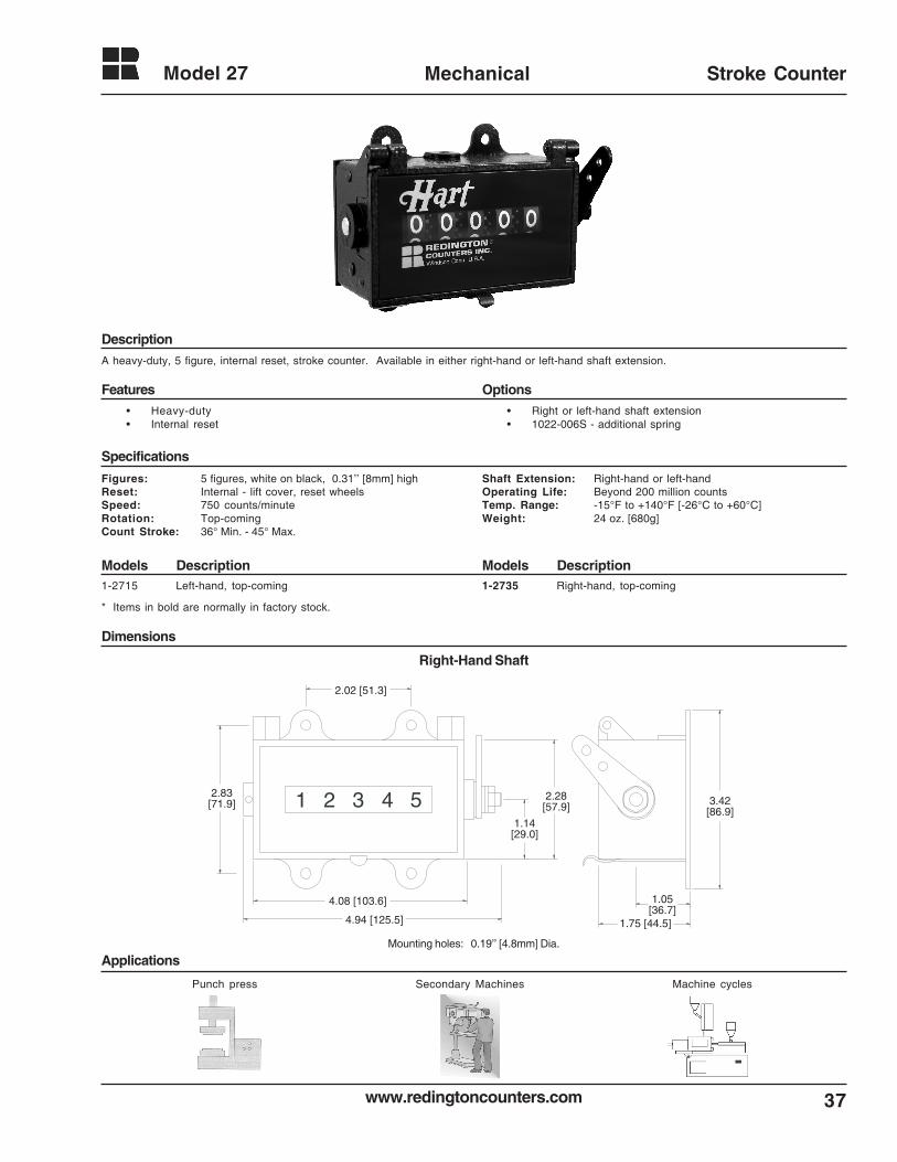
A heavy-duty, 5 figure, internal reset, stroke counter. Available in either right-hand or left-hand shaft extension.
Figures: 5 figures, white on black, 0.31’’ [8mm] highReset: Internal - lift cover, reset wheelsSpeed: 750 counts/minuteRotation: Top-comingCount Stroke: 36° Min. - 45° Max.
Shaft Extension: Right-hand or left-handOperating Life: Beyond 200 million countsTemp. Range: -15°F to +140°F [-26°C to +60°C]Weight: 24 oz. [680g]
1-2715 Left-hand, top-coming 1-2735 Right-hand, top-coming
321 4 5 3.42[86.9]
2.28[57.9]
1.14[29.0]
1.05[36.7]
1.75 [44.5]
2.02 [51.3]
2.83[71.9]
4.08 [103.6]
4.94 [125.5]
Right-Hand Shaft
Mounting holes: 0.19’’ [4.8mm] Dia.
• Right or left-hand shaft extension• 1022-006S - additional spring
• Heavy-duty• Internal reset
Punch press Machine cyclesSecondary Machines
* Items in bold are normally in factory stock.
Model 28
38
Mechanical
www.redingtoncounters.com
Stroke Counter
Description
Features Options
Specifications
Models DescriptionModels Description
Dimensions
Applications
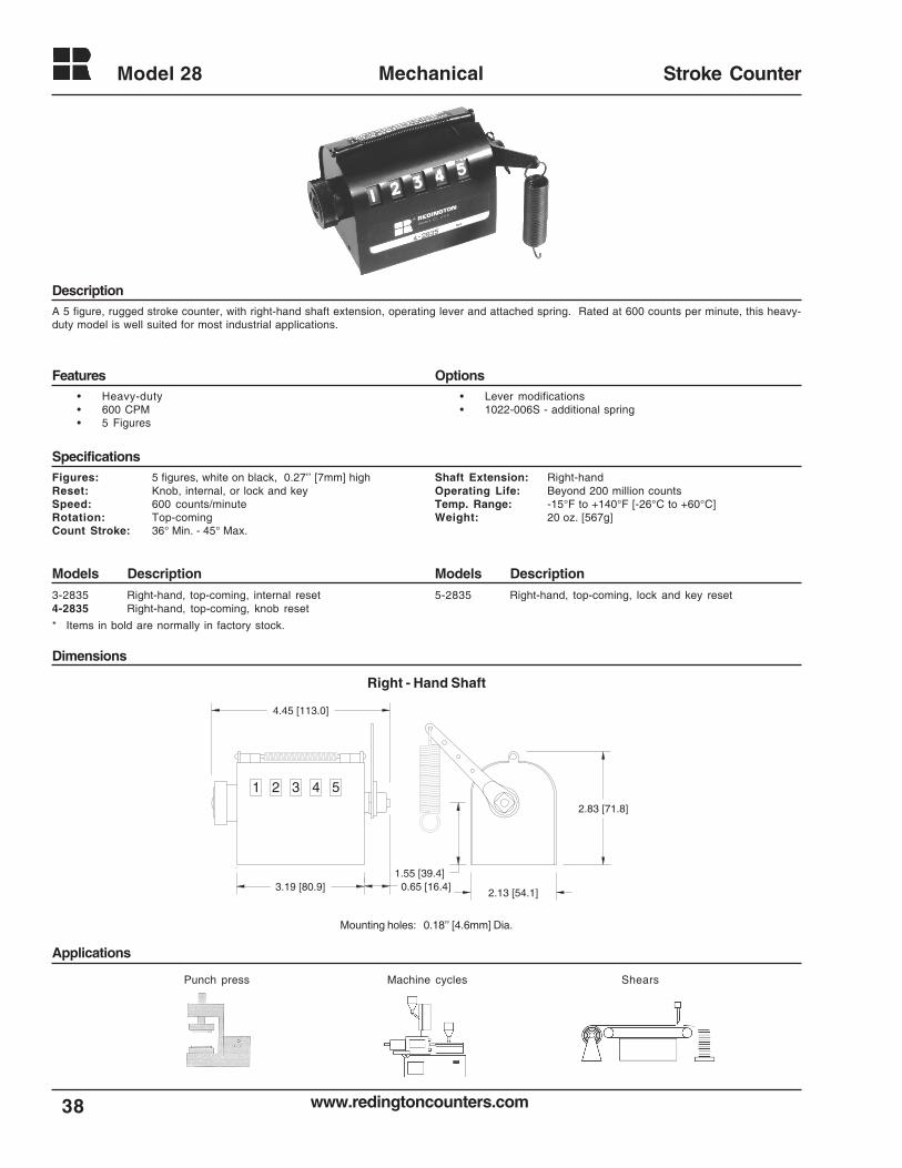
A 5 figure, rugged stroke counter, with right-hand shaft extension, operating lever and attached spring. Rated at 600 counts per minute, this heavy-duty model is well suited for most industrial applications.
• Lever modifications• 1022-006S - additional spring
Figures: 5 figures, white on black, 0.27’’ [7mm] highReset: Knob, internal, or lock and keySpeed: 600 counts/minuteRotation: Top-comingCount Stroke: 36° Min. - 45° Max.
Shaft Extension: Right-handOperating Life: Beyond 200 million countsTemp. Range: -15°F to +140°F [-26°C to +60°C]Weight: 20 oz. [567g]
3-2835 Right-hand, top-coming, internal reset4-2835 Right-hand, top-coming, knob reset
5-2835 Right-hand, top-coming, lock and key reset
1 2 3 4 5
2.13 [54.1]3.19 [80.9]
2.83 [71.8]
4.45 [113.0]
1.55 [39.4]0.65 [16.4]
Right - Hand Shaft
Mounting holes: 0.18’’ [4.6mm] Dia.
• Heavy-duty• 600 CPM• 5 Figures
Punch press ShearsMachine cycles
* Items in bold are normally in factory stock.
39www.redingtoncounters.com
Model 29 Mechanical Stroke Counter
Description
Features Options
Specifications
Models DescriptionModels Description
Dimensions
Applications
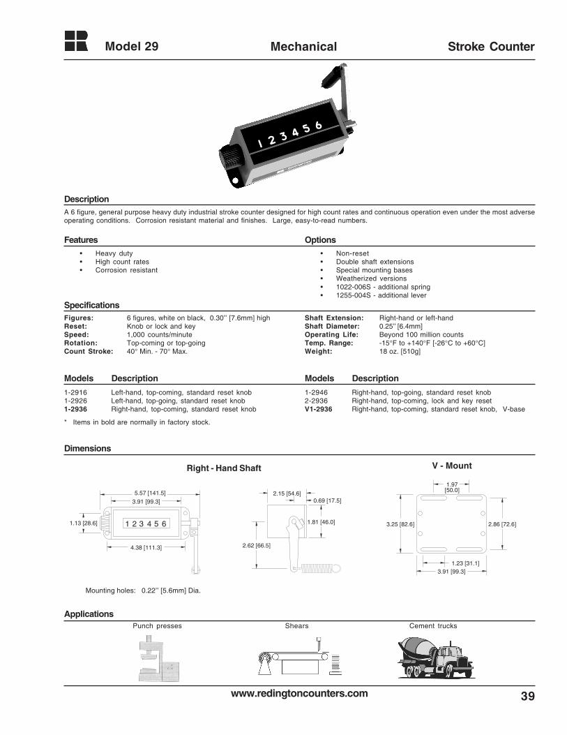
A 6 figure, general purpose heavy duty industrial stroke counter designed for high count rates and continuous operation even under the most adverseoperating conditions. Corrosion resistant material and finishes. Large, easy-to-read numbers.
• Non-reset• Double shaft extensions• Special mounting bases• Weatherized versions• 1022-006S - additional spring• 1255-004S - additional lever
Figures: 6 figures, white on black, 0.30’’ [7.6mm] highReset: Knob or lock and keySpeed: 1,000 counts/minuteRotation: Top-coming or top-goingCount Stroke: 40° Min. - 70° Max.
Shaft Extension: Right-hand or left-handShaft Diameter: 0.25’’ [6.4mm]Operating Life: Beyond 100 million countsTemp. Range: -15°F to +140°F [-26°C to +60°C]Weight: 18 oz. [510g]
1-2916 Left-hand, top-coming, standard reset knob1-2926 Left-hand, top-going, standard reset knob1-2936 Right-hand, top-coming, standard reset knob
1-2946 Right-hand, top-going, standard reset knob2-2936 Right-hand, top-coming, lock and key resetV1-2936 Right-hand, top-coming, standard reset knob, V-base
321 4 5 6
4.38 [111.3]
5.57 [141.5]
3.91 [99.3]
1.13 [28.6] 1.81 [46.0]
0.69 [17.5]2.15 [54.6]
2.62 [66.5]
1.97 [50.0]
2.86 [72.6]
1.23 [31.1]3.91 [99.3]
3.25 [82.6]
Right - Hand Shaft
Mounting holes: 0.22’’ [5.6mm] Dia.
V - Mount
• Heavy duty• High count rates• Corrosion resistant
Punch presses Cement trucksShears
* Items in bold are normally in factory stock.
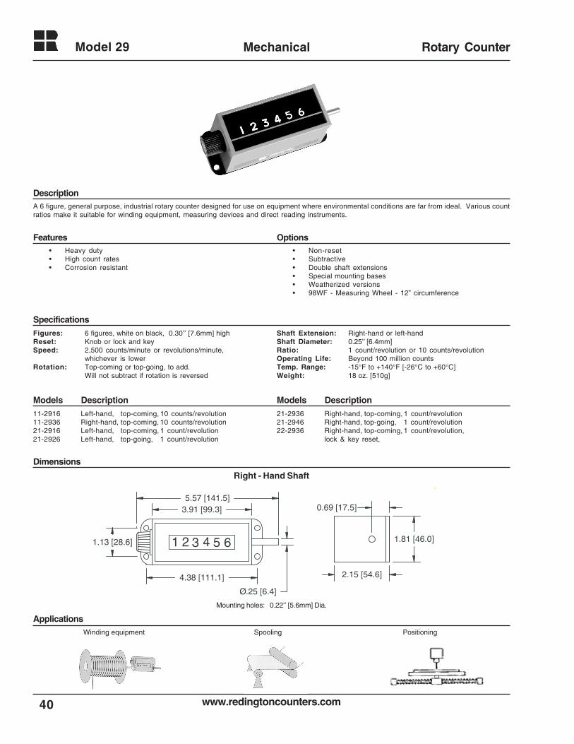
www.redingtoncounters.com
Model 29
40
Mechanical Rotary Counter
Description
Features Options
Specifications
Models DescriptionModels Description
Dimensions
Applications
A 6 figure, general purpose, industrial rotary counter designed for use on equipment where environmental conditions are far from ideal. Various countratios make it suitable for winding equipment, measuring devices and direct reading instruments.
• Non-reset• Subtractive• Double shaft extensions• Special mounting bases• Weatherized versions• 98WF - Measuring Wheel - 12” circumference
1.81 [46.0]
0.69 [17.5]
2.15 [54.6]
Ø.25 [6.4]
321 4 5 6
4.38 [111.1]
5.57 [141.5]3.91 [99.3]
1.13 [28.6]
Right - Hand Shaft
Mounting holes: 0.22’’ [5.6mm] Dia.
Figures: 6 figures, white on black, 0.30’’ [7.6mm] highReset: Knob or lock and keySpeed: 2,500 counts/minute or revolutions/minute,
whichever is lowerRotation: Top-coming or top-going, to add.
Will not subtract if rotation is reversed
Shaft Extension: Right-hand or left-handShaft Diameter: 0.25’’ [6.4mm]Ratio: 1 count/revolution or 10 counts/revolutionOperating Life: Beyond 100 million countsTemp. Range: -15°F to +140°F [-26°C to +60°C]Weight: 18 oz. [510g]
11-2916 Left-hand, top-coming, 10 counts/revolution11-2936 Right-hand, top-coming, 10 counts/revolution21-2916 Left-hand, top-coming, 1 count/revolution21-2926 Left-hand, top-going, 1 count/revolution
21-2936 Right-hand, top-coming, 1 count/revolution21-2946 Right-hand, top-going, 1 count/revolution22-2936 Right-hand, top-coming, 1 count/revolution,
lock & key reset,
Winding equipment
• Heavy duty• High count rates• Corrosion resistant
Spooling Positioning
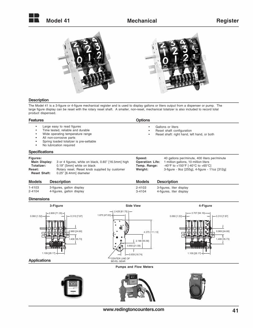
41www.redingtoncounters.com
Model 41 Mechanical Register
Description
Features Options
Specifications
Models DescriptionModels Description
Dimensions
Applications
Pumps and Flow Meters
The Model 41 is a 3-figure or 4-figure mechanical register and is used to display gallons or liters output from a dispenser or pump. Thelarge figure display can be reset with the rotary reset shaft. A smaller, non-reset, mechanical totalizer is also included to record totalproduct dispensed.
• Large easy to read figures• Time tested, reliable and durable• Wide operating temperature range• All non-corrosive parts• Spring loaded totalizer is pre-settable• No lubrication required
• Gallons or liters• Reset shaft configuration• Reset shaft: right hand, left hand, or both
Figures:Main Display: 3 or 4 figures, white on black, 0.65" [16.5mm] highTotalizer: 0.19” [5mm] white on black
Reset: Rotary reset. Reset knob supplied by customerReset Shaft: 0.25” [6.4mm] diameter
Speed: 40 gallons per/minute, 400 liters per/minuteOperation Life: 1 million gallons, 10 million litersTemp. Range: -40°F to +150°F [-40°C to +65°C]Weight: 3-figure - 9oz [255g], 4-figure - 11oz [312g]
1-4103 3-figures, gallon display2-4104 4-figures, gallon display
2-4103 3-figures, liter display3-4104 4-figures, liter display
3-Figure 4-FigureSide View

www.redingtoncounters.com
Model 46
42
Mechanical Stroke Counter
Description
Features Options
Specifications
Models DescriptionModels Description
Dimensions
Applications
These 5 figure stroke counters are especially designed for limited space and high count life applications. The advanced drive system translates intoexceptionally high operating speeds, extended operating life, for fast and accurate readings. Ideal for copiers, printing presses, cut-off machines, andpiece-part counting applications. Also available with a thumb lever for use as a tally counter.
• Special levers• 10011-001S - additional spring• 10007-009S - lever and spring
Figures: 5 figures, white on black, 0.19’’ [5mm] highReset: Standard or large knob, non-resetSpeed: 500 counts/minuteRotation: Top-coming or top-goingCount Stroke: 40° Min. - 45° Max.
Shaft Extension: Right-hand or left-handShaft Diameter: 0.156’’ [4.0mm]Operating Life: Beyond 5 million countsTemp. Range: -15°F to +140°F [-25°C to +60°C]Weight: 2 oz. [57g]
1-4615 Left-hand, top-coming, standard reset knob1-4625 Left-hand, top-going, standard reset knob1-4635 Right-hand, top-coming, standard reset knob1-4645 Right-hand, top-going, standard reset knob1-4635T Right-hand, top-coming, std. reset knob, with thumb lever
2-4615 Left-hand, top-coming, large reset knob2-4625 Left-hand, top-going, large reset knob2-4635 Right-hand, top-coming, large reset knob2-4645 Right-hand, top-going, large reset knob5-4645 Right-hand, top-going, non-reset
321 45
0.81 [20.6]
1.52 [38.6]
2.53 [64.3]
1.20 [30.5] 1.44 [36.6]
1.28 [32.5]
0.96 [24.4]
Right - Hand Shaft
Mounting holes: 0.13’’ x 0.24’’ [3.3 x 6.1mm] slots
Copiers
• Compact size• Reliability• Low cost
Farm equipment Piece-part counting Cut-off machinesPrinting presses
With Thumb LeverWith Lever & Spring
* Items in bold are normally in factory stock.
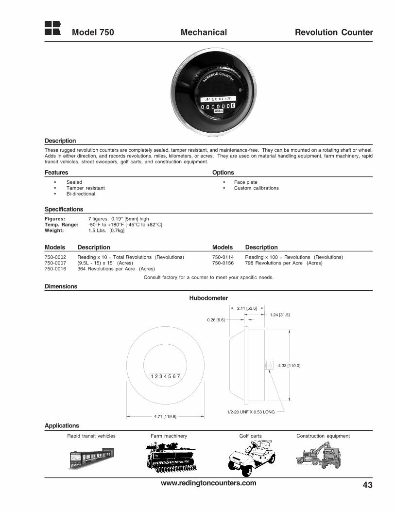
43www.redingtoncounters.com
Model 750 Mechanical Revolution Counter
Description
Features Options
Specifications
Models DescriptionModels Description
Dimensions
Applications
These rugged revolution counters are completely sealed, tamper resistant, and maintenance-free. They can be mounted on a rotating shaft or wheel.Adds in either direction, and records revolutions, miles, kilometers, or acres. They are used on material handling equipment, farm machinery, rapidtransit vehicles, street sweepers, golf carts, and construction equipment.
Figures: 7 figures, 0.19’’ [5mm] highTemp. Range: -50°F to +180°F [-45°C to +82°C]Weight: 1.5 Lbs. [0.7kg]
• Face plate• Custom calibrations
750-0002 Reading x 10 = Total Revolutions (Revolutions)750-0007 (9.5L - 15) x 15’ (Acres)750-0016 364 Revolutions per Acre (Acres)
750-0114 Reading x 100 = Revolutions (Revolutions)750-0156 798 Revolutions per Acre (Acres)
1 2 3 4 5 6 7
4.33 [110.0]
4.71 [119.6]
0.26 [6.6]1.24 [31.5]
2.11 [53.6]
1/2-20 UNF X 0.53 LONG
Hubodometer
Consult factory for a counter to meet your specific needs.
• Sealed• Tamper resistant• Bi-directional
Farm machineryRapid transit vehicles Construction equipmentGolf carts
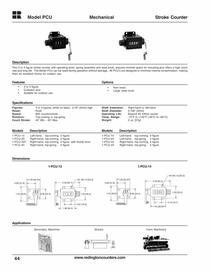
www.redingtoncounters.com
Model PCU
44
Mechanical Stroke Counter
Description
Specifications
Models DescriptionModels Description
Dimensions
Applications
This 3 or 4 figure stroke counter with operating lever, spring assembly and reset knob, requires minimal space for mounting plus offers a high countrate and long life. The Model PCU can be reset during operation without damage. All PCU’s are designed to minimize internal contamination, makingthem an excellent choice for outdoor use.
• Non-reset• Large reset knob
Figures: 3 or 4 figures, white on black, 0.19’’ [5mm] highReset: KnobSpeed: 600 counts/minuteRotation: Top-coming or top-goingCount Stroke: 40° Min. - 45° Max.
Shaft Extension: Right-hand or left-handShaft Diameter: 0.156’’ [4mm]Operating Life: Beyond 50 million countsTemp. Range: -15°F to +140°F [-26°C to +60°C]Weight: 2 oz. [57g]
1-PCU-13 Left-hand, top-coming, 3 figure1-PCU-33 Right-hand, top-coming, 3 figure1-PCU-33T Right-hand, top-coming, 3 figure, with thumb lever1-PCU-43 Right-hand, top-going, 3 figure
1-PCU-14 Left-hand, top-coming, 4 figure1-PCU-24 Left-hand, top-going, 4 figure1-PCU-34 Right-hand, top-coming, 4 figure1-PCU-44 Right-hand, top-going, 4 figure
Shears
Features Options• 3 or 4 figure• Compact size• Suitable for outdoor use
1-PCU-141-PCU-13
Secondary Machines Farm Machinery
1.44 [36.6]
0.67 [16.9]
1.38 [35.2]
2.39 [60.7]1.28 [32.5]
0.96 [24.4] 1.20 [30.4]1 2 3
0.85 [21.6]
4X Ø0.13 [Ø3.3]
1.44 [36.6]
1.28 [32.5]
0.96 [24.4]
0.85 [21.6]
0.74 [18.7]
1.45 [36.9]
2.46 [62.5]
1.20 [30.4]1 2 3 4
4X Ø0.13 [Ø3.3]
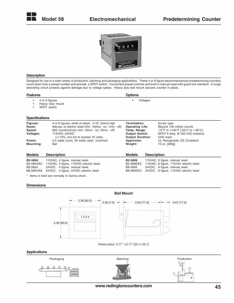
45www.redingtoncounters.com
Model 58 Electromechanical Predetermining Counter
Description
Features Options
Specifications
Models DescriptionModels Description
Dimensions
Applications
Designed for use in a wide variety of production, batching and packaging applications. These 4 or 6 figure electromechanical predetermining counterscount down from a preset number and activate a SPDT switch. Convenient preset controls and built-in manual reset with guard are standard. A surgeabsorbing circuit protects against damage due to voltage spikes. Heavy duty bail mount secures counter in place.
Figures: 4 or 6 figures, white on black, 0.16’’ [4mm] highReset: Manual, or electric reset (min. 100ms - on, 1min - off)Speed: 600 counts/minute (min. 50ms - on, 50ms - off)Voltages: 115VAC, 24VDC
(+/-10%, but not to exceed 10 volts)Power: 5.5 watts count, 20 watts reset (nominal)Mounting: Bail
• Voltages
Termination: Screw typeOperating Life: Beyond 100 million countsTemp. Range: -15°F to +140°F [-26°C to + 60°C]Output Switch: SPDT 5 Amp. @ 250 VAC resistiveOutput Duration: Until resetApprovals: UL Recognized, CE CompliantWeight: 10 oz. [284g]
B2-5804 115VAC, 4 figure, manual resetB2-5804/E2 115VAC, 4 figure, 115VAC electric resetB8-5804 24VDC, 4 figure, manual resetB8-5804/E8 24VDC, 4 figure, 24VDC electric reset
B2-5806 115VAC, 6 figure, manual resetB2-5806/E2 115VAC, 6 figure, 115VAC electric resetB8-5806 24VDC, 6 figure, manual resetB8-5806/E2 24VDC, 6 figure, 115VAC electric reset
1 2 3 4
2.36 [60.0]2.83 [71.8]0.28 [7.0] 0.67 [17.0]
2.36 [60.0]
Bail Mount
Panel cutout: 2.17’’ x 2.17’’ [55.1 x 55.1]
• 4 or 6 figures• Heavy duty mount• SPDT switch
ProductionBatchingPackaging
* Items in bold are normally in factory stock.
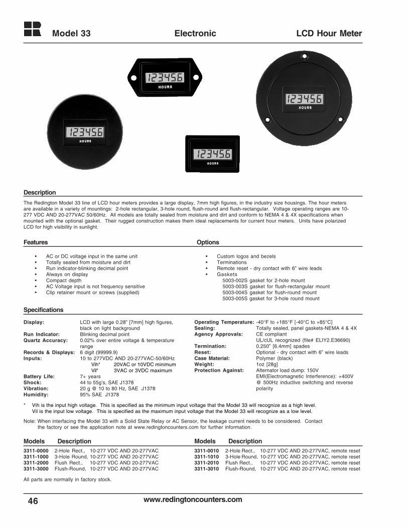
www.redingtoncounters.com
Model 33
46
Electronic LCD Hour Meter
Description
Features Options
Specifications
The Redington Model 33 line of LCD hour meters provides a large display, 7mm high figures, in the industry size housings. The hour metersare available in a variety of mountings: 2-hole rectangular, 3-hole round, flush-round and flush-rectangular. Voltage operating ranges are 10-277 VDC AND 20-277VAC 50/60Hz. All models are totally sealed from moisture and dirt and conform to NEMA 4 & 4X specifications whenmounted with the optional gasket. Their rugged construction makes them ideal replacements for current hour meters. Units have polarizedLCD for high visibility in sunlight.
• AC or DC voltage input in the same unit• Totally sealed from moisture and dirt• Run indicator-blinking decimal point• Always on display• Compact depth• AC Voltage input is not frequency sensitive• Clip retainer mount or screws (supplied)
• Custom logos and bezels• Terminations• Remote reset - dry contact with 6” wire leads• Gaskets
5003-002S gasket for 2-hole mount5003-003S gasket for flush-rectangular mount5003-004S gasket for flush-round mount5003-005S gasket for 3-hole round mount
Display: LCD with large 0.28” [7mm] high figures,black on light background
Run Indicator: Blinking decimal pointQuartz Accuracy: 0.02% over entire voltage & temperature
rangeRecords & Displays: 6 digit (99999.9)Inputs: 10 to 277VDC AND 20-277VAC-50/60Hz
Vih* 20VAC or 10VDC minimumVil* 3VAC or 3VDC maximum
Battery Life: 7+ yearsShock: 44 to 55g’s, SAE J1378Vibration: 20 g @ 10 to 80 Hz, SAE J1378Humidity: 95% SAE J1378
Operating Temperature: -40°F to +185°F [-40°C to +85°C]Sealing: Totally sealed, panel gaskets-NEMA 4 & 4XAgency Approvals: CE compliant
UL/cUL recognized (file# ELIY2.E36690)Termination: 0.250” [6.4mm] spadesReset: Optional - dry contact with 6” wire leadsCase Material: Polymer (black)Weight: 1oz [28g]Protection Against: Alternator load dump: 150V
EMI(Electromagnetic Interference): +400V@ 500Hz inductive switching and reversepolarity
3311-0000 2-Hole Rect., 10-277 VDC AND 20-277VAC3311-1000 3-Hole Round, 10-277 VDC AND 20-277VAC3311-2000 Flush Rect., 10-277 VDC AND 20-277VAC3311-3000 Flush-Round, 10-277 VDC AND 20-277VAC
* Vih is the input high voltage. This is specified as the minimum input voltage that the Model 33 will recognize as a high level.Vil is the input low voltage. This is specified as the maximum input voltage that the Model 33 will recognize as a low level.
All parts are normally in factory stock.
3311-0010 2-Hole Rect., 10-277 VDC AND 20-277VAC, remote reset3311-1010 3-Hole Round, 10-277 VDC AND 20-277VAC, remote reset3311-2010 Flush Rect., 10-277 VDC AND 20-277VAC, remote reset3311-3010 Flush-Round, 10-277 VDC AND 20-277VAC, remote reset
Models Description Models Description
Note: When interfacing the Model 33 with a Solid State Relay or AC Sensor, the leakage current needs to be considered. Contactthe factory or see the application note at www.redingtoncounters.com for further information.
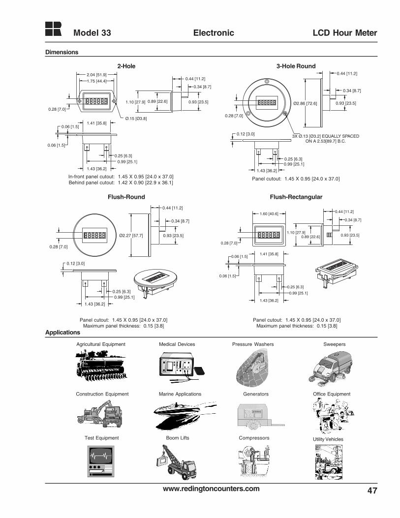
47www.redingtoncounters.com
Model 33 Electronic LCD Hour Meter
Dimensions
Applications
0.28 [7.0]
2.04 [51.9]
1.75 [44.4]
Ø.15 [Ø3.8]
1.10 [27.9]
0.44 [11.2]
0.34 [8.7]
0.93 [23.5]
0.25 [6.3]
1.43 [36.2]
0.99 [25.1]
0.06 [1.5]
0.06 [1.5]1.41 [35.8]
0.89 [22.6]
0.28 [7.0]
0.12 [3.0]
0.25 [6.3]0.99 [25.1]
1.43 [36.2]
Ø2.86 [72.6] 0.93 [23.5]
0.34 [8.7]
0.44 [11.2]
3X Ø.13 [Ø3.2] EQUALLY SPACED ON A 2.53[89.7] B.C.
0.28 [7.0]
1.60 [40.6]
1.10 [27.9]
0.44 [11.2]
0.34 [8.7]
0.93 [23.5]
0.06 [1.5]
0.06 [1.5]
1.43 [36.2]
0.99 [25.1]
0.25 [6.3]
1.41 [35.8]
0.89 [22.6]
0.25 [6.3]
1.43 [36.2]
0.99 [25.1]
0.12 [3.0]
0.34 [8.7]
0.93 [23.5]
0.44 [11.2]
Ø2.27 [57.7]
0.28 [7.0]
2-Hole 3-Hole Round
Flush-Round Flush-Rectangular
Agricultural Equipment
Compressors
Medical Devices
Marine ApplicationsConstruction Equipment Generators
Utility Vehicles
Pressure Washers Sweepers
Boom LiftsTest Equipment
Office Equipment
In-front panel cutout: 1.45 X 0.95 [24.0 x 37.0]Behind panel cutout: 1.42 X 0.90 [22.9 x 36.1]
Panel cutout: 1.45 X 0.95 [24.0 x 37.0]
Panel cutout: 1.45 X 0.95 [24.0 x 37.0]Maximum panel thickness: 0.15 [3.8]
Panel cutout: 1.45 X 0.95 [24.0 x 37.0]Maximum panel thickness: 0.15 [3.8]
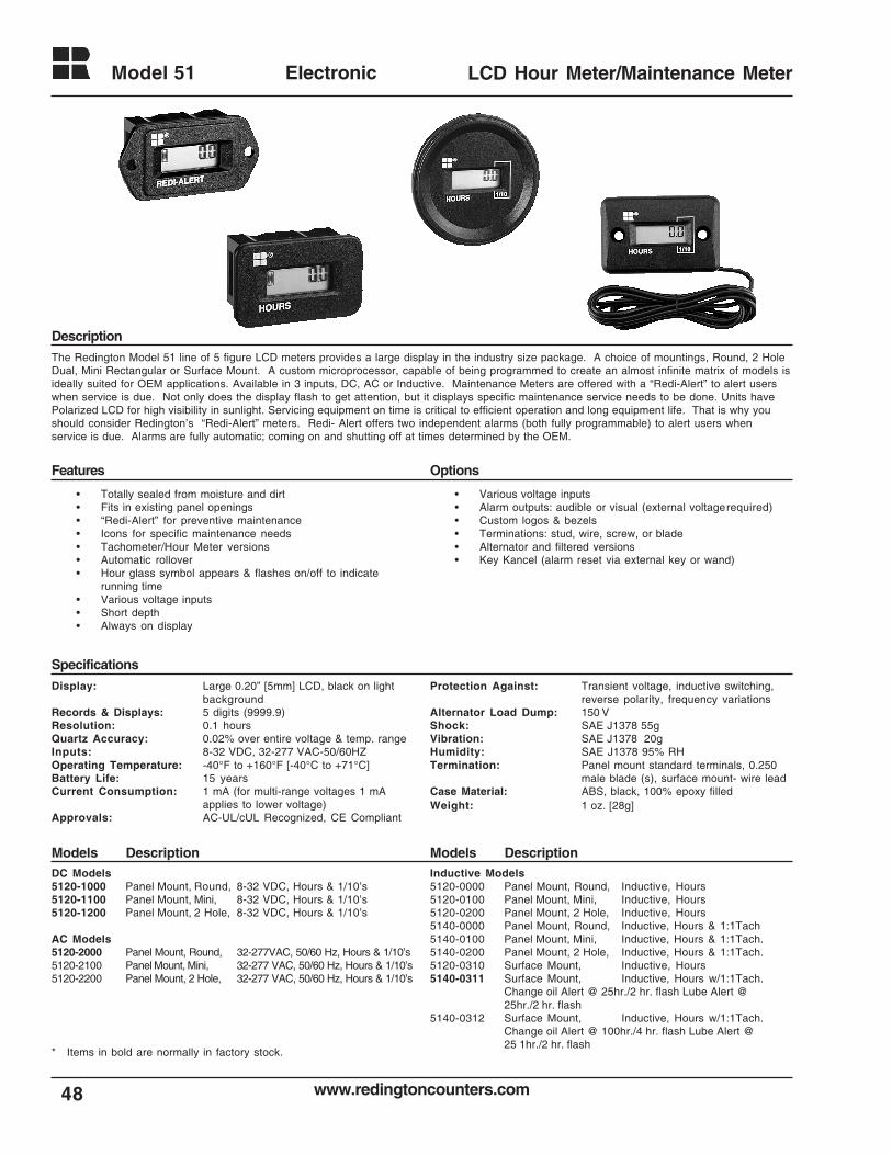
www.redingtoncounters.com
Model 51
48
Electronic LCD Hour Meter/Maintenance Meter
Options
The Redington Model 51 line of 5 figure LCD meters provides a large display in the industry size package. A choice of mountings, Round, 2 HoleDual, Mini Rectangular or Surface Mount. A custom microprocessor, capable of being programmed to create an almost infinite matrix of models isideally suited for OEM applications. Available in 3 inputs, DC, AC or Inductive. Maintenance Meters are offered with a “Redi-Alert” to alert userswhen service is due. Not only does the display flash to get attention, but it displays specific maintenance service needs to be done. Units havePolarized LCD for high visibility in sunlight. Servicing equipment on time is critical to efficient operation and long equipment life. That is why youshould consider Redington’s “Redi-Alert” meters. Redi- Alert offers two independent alarms (both fully programmable) to alert users whenservice is due. Alarms are fully automatic; coming on and shutting off at times determined by the OEM.
• Totally sealed from moisture and dirt• Fits in existing panel openings• “Redi-Alert” for preventive maintenance• Icons for specific maintenance needs• Tachometer/Hour Meter versions• Automatic rollover• Hour glass symbol appears & flashes on/off to indicate
running time• Various voltage inputs• Short depth• Always on display
• Various voltage inputs• Alarm outputs: audible or visual (external voltagerequired)• Custom logos & bezels• Terminations: stud, wire, screw, or blade• Alternator and filtered versions• Key Kancel (alarm reset via external key or wand)
Display: Large 0.20” [5mm] LCD, black on lightbackground
Records & Displays: 5 digits (9999.9)Resolution: 0.1 hoursQuartz Accuracy: 0.02% over entire voltage & temp. rangeInputs: 8-32 VDC, 32-277 VAC-50/60HZOperating Temperature: -40°F to +160°F [-40°C to +71°C]Battery Life: 15 yearsCurrent Consumption: 1 mA (for multi-range voltages 1 mA
applies to lower voltage)Approvals: AC-UL/cUL Recognized, CE Compliant
Protection Against: Transient voltage, inductive switching,reverse polarity, frequency variations
Alternator Load Dump: 150 VShock: SAE J1378 55gVibration: SAE J1378 20gHumidity: SAE J1378 95% RHTermination: Panel mount standard terminals, 0.250
male blade (s), surface mount- wire leadCase Material: ABS, black, 100% epoxy filledWeight: 1 oz. [28g]
DC Models5120-1000 Panel Mount, Round, 8-32 VDC, Hours & 1/10’s5120-1100 Panel Mount, Mini, 8-32 VDC, Hours & 1/10’s5120-1200 Panel Mount, 2 Hole, 8-32 VDC, Hours & 1/10’s
AC Models5120-2000 Panel Mount, Round, 32-277VAC, 50/60 Hz, Hours & 1/10’s5120-2100 Panel Mount, Mini, 32-277 VAC, 50/60 Hz, Hours & 1/10’s5120-2200 Panel Mount, 2 Hole, 32-277 VAC, 50/60 Hz, Hours & 1/10’s
Models DescriptionModels Description
Specifications
Features
Description
Inductive Models5120-0000 Panel Mount, Round, Inductive, Hours5120-0100 Panel Mount, Mini, Inductive, Hours5120-0200 Panel Mount, 2 Hole, Inductive, Hours5140-0000 Panel Mount, Round, Inductive, Hours & 1:1Tach5140-0100 Panel Mount, Mini, Inductive, Hours & 1:1Tach.5140-0200 Panel Mount, 2 Hole, Inductive, Hours & 1:1Tach.5120-0310 Surface Mount, Inductive, Hours5140-0311 Surface Mount, Inductive, Hours w/1:1Tach.
Change oil Alert @ 25hr./2 hr. flash Lube Alert @25hr./2 hr. flash
5140-0312 Surface Mount, Inductive, Hours w/1:1Tach.Change oil Alert @ 100hr./4 hr. flash Lube Alert @25 1hr./2 hr. flash
* Items in bold are normally in factory stock.
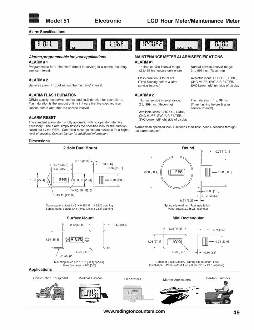
49www.redingtoncounters.com
Model 51 Electronic LCD Hour Meter/Maintenance Meter
2.12 [53.8]
1.39 [35.3]
R0.20 [R5.1]
0.50 [12.7]
22 Gauge
1.75 [44.5]
1.08 [27.4]
0.75 [19.1]
0.94 [23.9]
0.10 [2.5]R0.20 [R5.1]
1.40 [35.6]1.75 [44.5]
0.94 [23.9]
0.75 [19.1]0.10 [2.6]
0.15 [3.9]
0.92 [23.4]1.08 [27.4]
R0.10 [R2.5]
Ø0.15 [Ø3.8]
2 Hole Dual Mount Round
Surface Mount Mini Rectangular
Above panel cutout 1.46 x 0.95 [37.1 x 24.1] openingBehind panel cutout 1.41 x 0.93 [35.8 x 23.6] opening
Spring clip retainer, Fast installation Panel cutout 2.0 [50.8] diameter
Mounting holes are 1 1/2” [38.1] spacingHole Diameter is 1/8” [3.2]
Compact Bezel Design, Spring clip retainer, Fastinstallation, Panel cutout 1.46 x 0.95 [37.1 x 24.1] opening.
Alarm Specifications
Alarms programmable for your applicationsALARM # 1Programmable for a “first time” (break in service) or a normal recurringservice interval.
ALARM # 2Same as alarm # 1, but without the “first time” interval.
ALARM/ FLASH DURATIONOEM’s specify the service interval and flash duration for each alarm.Flash duration is the amount of time in hours that the specified iconflashes before and after the service interval.
ALARM RESETThe standard alarm alert is fully automatic with no operator interfacenecessary. The alarm simply flashes the specified icon for the durationcalled out by the OEM. Controlled reset options are available for a higherlevel of security. Contact factory for additional information.
MAINTENANCE METER ALARM SPECIFICATIONSALARM #1
1st time service interval range Normal service interval range: (2 to 99 hrs. occurs only once) 2 to 999 hrs. (Recurring)
Flash duration: 1 to 99 hrs. Available icons: CHG OIL, LUBE,(Time flashing before & after CHG MUFF, SVC-AIR FILTER,service interval) SVC-Lower left/right side of display
ALARM # 2 Normal service interval range: Flash duration: 1 to 99 hrs. 2 to 999 hrs. (Recurring) (Time flashing before & after
service interval) Available icons: CHG OIL, LUBE, CHG MUFF, SVC-AIR FILTER, SVC-Lower left/right side of display
Alarms flash specified icon 4 seconds then flash hour 4 seconds through-out alarm duration.
Dimensions
Applications
GeneratorsConstruction Equipment Garden TractorsMarine ApplicationsMedical Devices
2.30 [58.4]
0.75 [19.1]
0.05 [1.3]
0.13 [3.3]
0.21 [5.2]
1.98 [50.3]
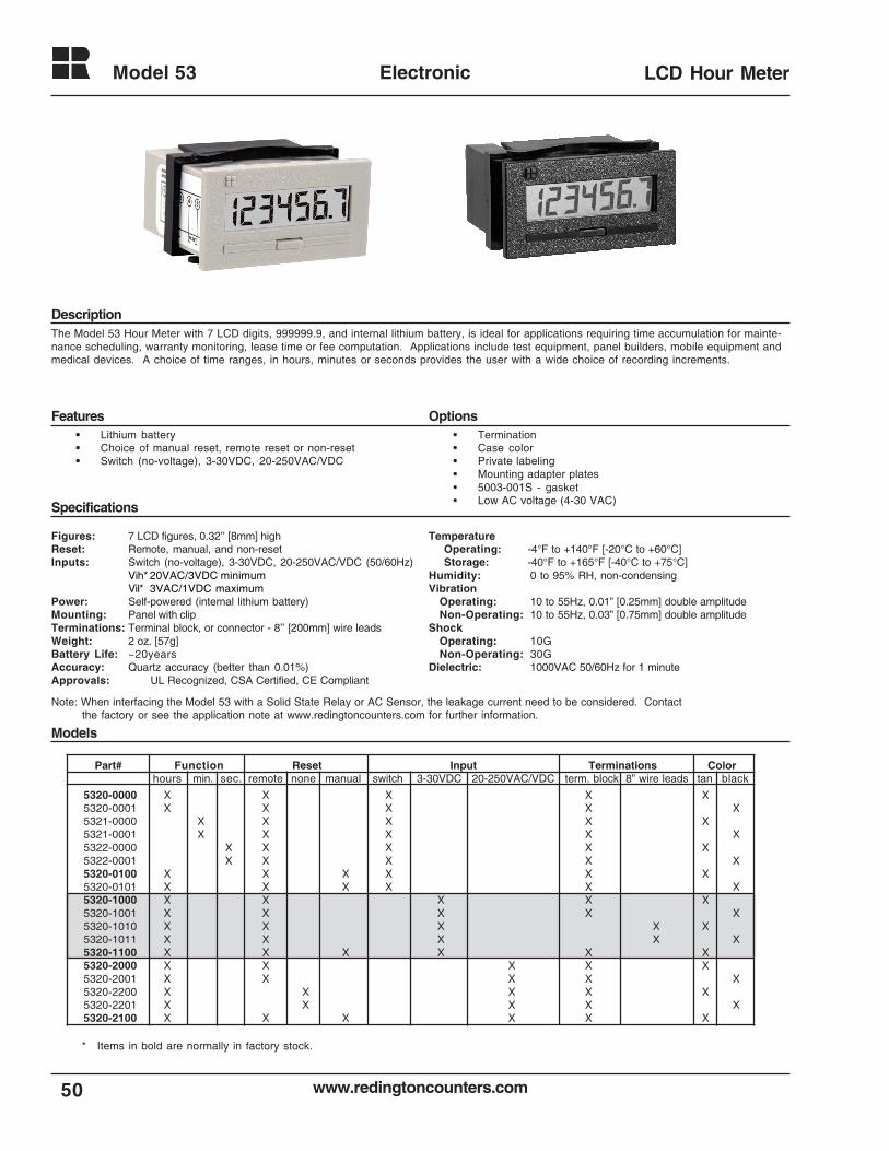
www.redingtoncounters.com
Model 53
50
Electronic LCD Hour Meter
Part# Function Reset Input Terminations Colorhours min. sec. remote none manual switch 3-30VDC 20-250VAC/VDC term. block 8” wire leads tan black
The Model 53 Hour Meter with 7 LCD digits, 999999.9, and internal lithium battery, is ideal for applications requiring time accumulation for mainte-nance scheduling, warranty monitoring, lease time or fee computation. Applications include test equipment, panel builders, mobile equipment andmedical devices. A choice of time ranges, in hours, minutes or seconds provides the user with a wide choice of recording increments.
Figures: 7 LCD figures, 0.32’’ [8mm] highReset: Remote, manual, and non-resetInputs: Switch (no-voltage), 3-30VDC, 20-250VAC/VDC (50/60Hz)
Vih* 20VAC/3VDC minimumVil* 3VAC/1VDC maximum
Power: Self-powered (internal lithium battery)Mounting: Panel with clipTerminations: Terminal block, or connector - 8’’ [200mm] wire leadsWeight: 2 oz. [57g]Battery Life: ~20yearsAccuracy: Quartz accuracy (better than 0.01%)Approvals: UL Recognized, CSA Certified, CE Compliant
• Lithium battery• Choice of manual reset, remote reset or non-reset• Switch (no-voltage), 3-30VDC, 20-250VAC/VDC
• Termination• Case color• Private labeling• Mounting adapter plates• 5003-001S - gasket• Low AC voltage (4-30 VAC)Specifications
Features Options
Description
TemperatureOperating: -4°F to +140°F [-20°C to +60°C]Storage: -40°F to +165°F [-40°C to +75°C]
Humidity: 0 to 95% RH, non-condensingVibration
Operating: 10 to 55Hz, 0.01” [0.25mm] double amplitudeNon-Operating: 10 to 55Hz, 0.03” [0.75mm] double amplitude
ShockOperating: 10GNon-Operating: 30G
Dielectric: 1000VAC 50/60Hz for 1 minute
5320-0000 X X X X X5320-0001 X X X X X5321-0000 X X X X X5321-0001 X X X X X5322-0000 X X X X X5322-0001 X X X X X5320-0100 X X X X X X5320-0101 X X X X X X5320-1000 X X X X X5320-1001 X X X X X5320-1010 X X X X X5320-1011 X X X X X5320-1100 X X X X X X5320-2000 X X X X X5320-2001 X X X X X5320-2200 X X X X X5320-2201 X X X X X5320-2100 X X X X X X
Models
* Items in bold are normally in factory stock.
Note: When interfacing the Model 53 with a Solid State Relay or AC Sensor, the leakage current need to be considered. Contactthe factory or see the application note at www.redingtoncounters.com for further information.
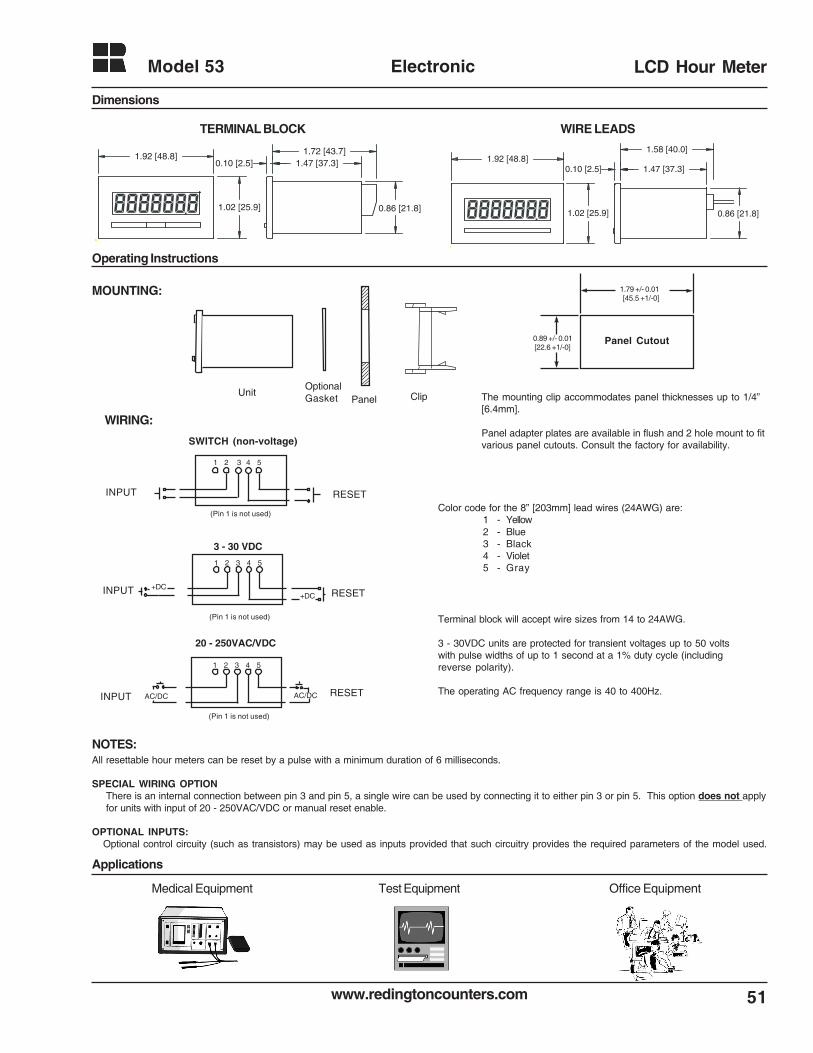
www.redingtoncounters.com 51
Model 53 Electronic LCD Hour Meter
MOUNTING:
UnitOptionalGasket Panel Clip
WIRING:
The mounting clip accommodates panel thicknesses up to 1/4”[6.4mm].
Panel adapter plates are available in flush and 2 hole mount to fitvarious panel cutouts. Consult the factory for availability.
Color code for the 8” [203mm] lead wires (24AWG) are:1 - Yellow2 - Blue3 - Black4 - Violet5 - Gray
NOTES:All resettable hour meters can be reset by a pulse with a minimum duration of 6 milliseconds.
SPECIAL WIRING OPTIONThere is an internal connection between pin 3 and pin 5, a single wire can be used by connecting it to either pin 3 or pin 5. This option does not applyfor units with input of 20 - 250VAC/VDC or manual reset enable.
OPTIONAL INPUTS:Optional control circuity (such as transistors) may be used as inputs provided that such circuitry provides the required parameters of the model used.
1.79 +/- 0.01 [45.5 +1/-0]
0.89 +/- 0.01 [22.6 +1/-0]
Panel Cutout
Terminal block will accept wire sizes from 14 to 24AWG.
3 - 30VDC units are protected for transient voltages up to 50 voltswith pulse widths of up to 1 second at a 1% duty cycle (includingreverse polarity).
The operating AC frequency range is 40 to 400Hz.
Operating Instructions
TERMINAL BLOCK WIRE LEADS
0.86 [21.8]
0.10 [2.5]
1.58 [40.0]
1.02 [25.9]
1.47 [37.3]1.92 [48.8]
Applications
Dimensions
Medical Equipment Test Equipment Office Equipment
(Pin 1 is not used)
RESETINPUT
20 - 250VAC/VDC
1 2 3 4 5
AC/DC AC/DC
RESETINPUT
(Pin 1 is not used)
3 - 30 VDC
1 2 3 4 5
+DC+DC
SWITCH (non-voltage)
RESETINPUT
(Pin 1 is not used)
1 2 3 4 5
0.86 [21.8]
0.10 [2.5]1.72 [43.7]
1.02 [25.9]
1.47 [37.3]1.92 [48.8]
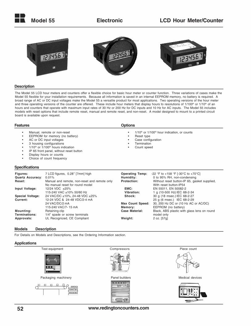
www.redingtoncounters.com
Model 55
52
Electronic LCD Hour Meter/Counter
• 1/10th or 1/100th hour indication, or counts• Reset type• Case configuration• Termination• Count speed
• Manual, remote or non-reset• EEPROM for memory (no battery)• AC or DC input voltages• 3 housing configurations• 1/10th or 1/100th hours indication• IP 65 front panel, without reset button• Display hours or counts• Choice of count frequency
The Model 55 LCD hour meters and counters offer a flexible choice for basic hour meter or counter function. Three variations of cases make theModel 55 flexible for your installation requirements. Because all information is saved in an internal EEPROM memory, no battery is required. Abroad range of AC or DC input voltages make the Model 55 a versatile product for most applications. Two operating versions of the hour meterand three operating versions of the counter are offered. These include hour meters that display hours to resolutions of 1/100th or 1/10th of anhours and counters that operate with maximum input rates of 30 Hz or 200 Hz for DC inputs and 10 Hz for AC inputs. The Model 55 includesmodels with reset options that include remote reset, manual and remote reset, and non-reset. A model designed to mount to a printed circuitboard is available upon request.
Figures: 7 LCD figures, 0.28’’ [7mm] highQuartz Accuracy: 0.01%Reset: Manual and remote, non-reset and remote only
No manual reset for round modelInput Voltage: 12/24 VDC ±25%
115-240 VAC ±10% 50/60 HzSpecial Voltage: 24 VAC/DC ±10%, 24-48 VDC ±25%Current: 12-24 VDC & 24-48 VDC/2-4 mA
24 VAC/DC/2 mA115-240 VAC/7- 15 mA
Mounting: Retaining clipTerminations: 1/4” spade or screw terminalsApprovals: UL Recognized, CE Compliant
Operating Temp: -22 °F to +158 °F [-30°C to +70°C]Humidity: 0 to 95% RH, non-condensingProtection: Without reset button-IP 65, gasket supplied,
With reset button-IP54EMC: EN 55011, EN 50082-2Vibration: 1 g (10-500 Hz) IEC 68-2-34Shock: 30 g (18 msec.) IEC 68-2-27
25 g (6 msec.) IEC 68-2-29Max Count Speed: 30, 200 Hz DC or (10 Hz AC or AC/DC)Memory: EEPROM (no battery)Case Material: Black, ABS plastic with glass lens on round
model onlyWeight: 2 oz. [57g]
For Details on Models and Descriptions, see the Ordering Information section.
Description
Specifications
Models Description
Applications
Panel builders Medical devicesPackaging machinery
Test equipment Compressors Piece count
OptionsFeatures
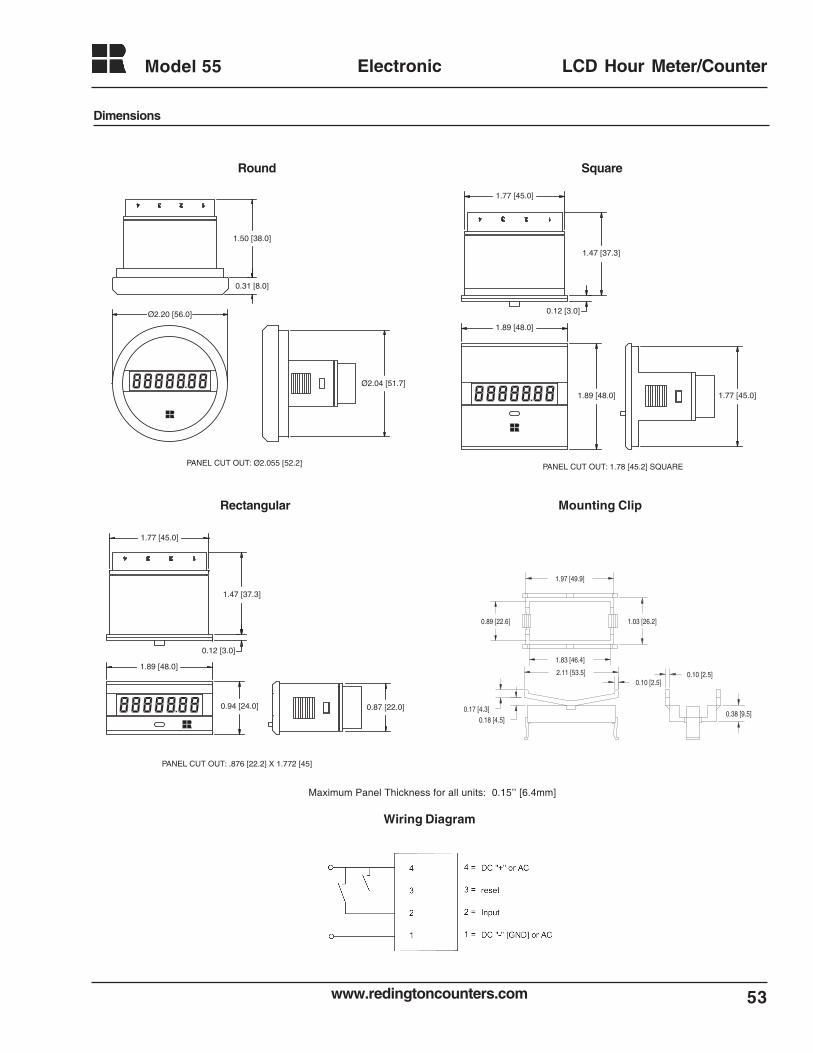
53www.redingtoncounters.com
Model 55 Electronic LCD Hour Meter/Counter
Dimensions
1.77 [45.0]
1.47 [37.3]
0.12 [3.0]
1.89 [48.0]
1.89 [48.0] 1.77 [45.0]
PANEL CUT OUT: 1.78 [45.2] SQUARE
1.77 [45.0]
1.47 [37.3]
0.12 [3.0]
0.94 [24.0]
1.89 [48.0]
0.87 [22.0]
PANEL CUT OUT: .876 [22.2] X 1.772 [45]
0.31 [8.0]
1.50 [38.0]
Ø2.20 [56.0]
Ø2.04 [51.7]
PANEL CUT OUT: Ø2.055 [52.2]
0.10 [2.5]
0.38 [9.5]0.18 [4.5]
0.17 [4.3]
0.89 [22.6] 1.03 [26.2]
1.97 [49.9]
1.83 [46.4]
2.11 [53.5]0.10 [2.5]
Rectangular
SquareRound
Mounting Clip
Maximum Panel Thickness for all units: 0.15’’ [6.4mm]
Wiring Diagram
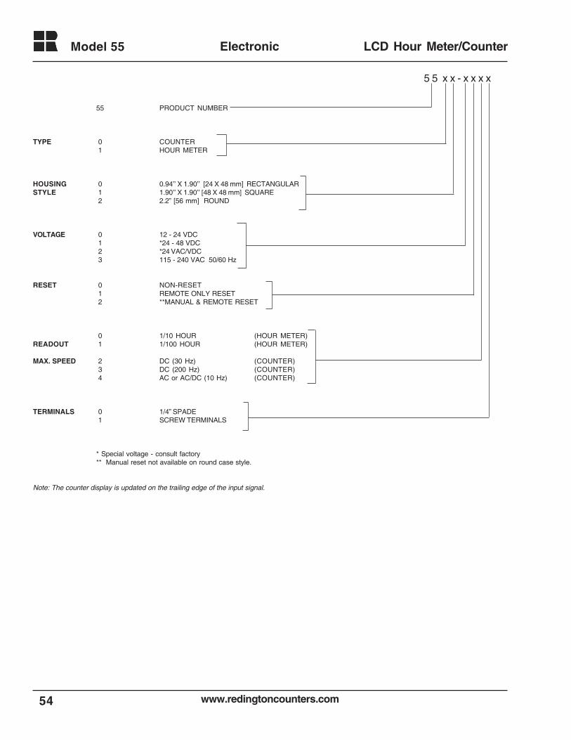
www.redingtoncounters.com
Model 55
54
Electronic LCD Hour Meter/Counter
55 PRODUCT NUMBER
TYPE 0 COUNTER 1 HOUR METER
HOUSING 0 0.94’’ X 1.90’’ [24 X 48 mm] RECTANGULARSTYLE 1 1.90’’ X 1.90’’ [48 X 48 mm] SQUARE
2 2.2” [56 mm] ROUND
VOLTAGE 0 12 - 24 VDC 1 *24 - 48 VDC 2 *24 VAC/VDC 3 115 - 240 VAC 50/60 Hz
RESET 0 NON-RESET 1 REMOTE ONLY RESET 2 **MANUAL & REMOTE RESET
0 1/10 HOUR (HOUR METER)READOUT 1 1/100 HOUR (HOUR METER)
MAX. SPEED 2 DC (30 Hz) (COUNTER) 3 DC (200 Hz) (COUNTER) 4 AC or AC/DC (10 Hz) (COUNTER)
TERMINALS 0 1/4” SPADE 1 SCREW TERMINALS
* Special voltage - consult factory** Manual reset not available on round case style.
Note: The counter display is updated on the trailing edge of the input signal.
5 5 x x - x x x x
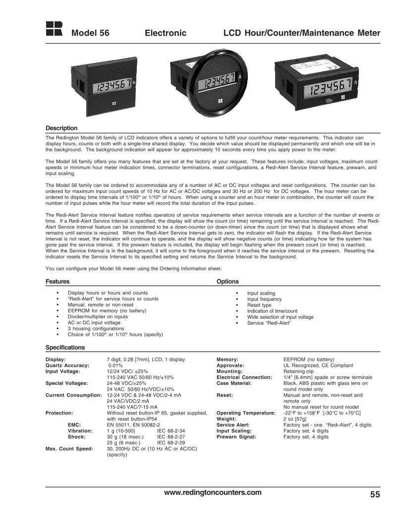
55www.redingtoncounters.com
Model 56 Electronic LCD Hour/Counter/Maintenance Meter
The Redington Model 56 family of LCD indicators offers a variety of options to fulfill your count/hour meter requirements. This indicator candisplay hours, counts or both with a single-line shared display. You decide which value should be displayed permanently and which one will be inthe background. The background indication will appear for approximately 10 seconds every time you apply power to the meter.
The Model 56 family offers you many features that are set at the factory at your request. These features include, input voltages, maximum countspeeds or minimum hour meter indication times, connector terminations, reset configurations, a Redi-Alert Service Interval feature, prewarn, andinput scaling.
The Model 56 family can be ordered to accommodate any of a number of AC or DC input voltages and reset configurations. The counter can beordered for maximum input count speeds of 10 Hz for AC or AC/DC voltages and 30 Hz or 200 Hz for DC voltages. The hour meter can beordered to display time intervals of 1/100th or 1/10th of hours. When using a counter and an hour meter in combination, the counter will count thenumber of input pulses while the hour meter will record the total duration of the input pulses.
The Redi-Alert Service Interval feature notifies operators of service requirements when service intervals are a function of the number of events ortime. If a Redi-Alert Service Interval is specified, the display will show the count (or time) remaining until the service interval is reached. The Redi-Alert Service Interval feature can be considered to be a down-counter (or down-timer) since the count (or time) that is displayed shows whatremains until service is required. When the Redi-Alert Service Interval gets to zero, the indicator will flash the display. If the Redi-Alert ServiceInterval is not reset, the indicator will continue to operate, and the display will show negative counts (or time) indicating how far the system hasgone past the service interval. If the prewarn feature is included, the display will begin flashing when the prewarn count (or time) is reached.When the Service Interval is in the background, it will come to the foreground when it reaches the service interval or the prewarn. Resetting theindicator resets the Service Interval to its specified setting and returns the Service Interval to the background.
You can configure your Model 56 meter using the Ordering Information sheet.
Display: 7 digit, 0.28 [7mm], LCD, 1 displayQuartz Accuracy: 0.01%Input Voltage: 12/24 VDC/ ±25%
115-240 VAC 50/60 Hz/±10%Special Voltages: 24-48 VDC/±25%
24 VAC 50/60 Hz/VDC/±10%Current Consumption: 12-24 VDC & 24-48 VDC/2-4 mA
24 VAC/VDC/2 mA115-240 VAC/7-15 mA
Protection: Without reset button-IP 65, gasket supplied,with reset button-IP54
EMC: EN 55011, EN 50082-2Vibration: 1 g (10-500) IEC 68-2-34Shock: 30 g (18 msec.) IEC 68-2-27
25 g (6 msec.) IEC 68-2-29Max. Count Speed: 30, 200Hz DC or (10 Hz AC or AC/DC)
(specify)
Specifications
Features Options
Description
• Display hours or hours and counts• “Redi-Alert” for service hours or counts• Manual, remote or non-reset• EEPROM for memory (no battery)• Divider/multiplier on inputs• AC or DC input voltage• 3 housing configurations• Choice of 1/100th or 1/10th hours (specify)
• Input scaling• Input frequency• Reset type• Indication of time/count• Wide selection of input voltage• Service “Redi-Alert”
Memory: EEPROM (no battery)Approvals: UL Recognized, CE CompliantMounting: Retaining clipElectrical Connection: 1/4” [6.4mm] spade or screw terminalsCase Material: Black, ABS plastic with glass lens on
round model onlyReset: Manual and remote, non-reset and
remote onlyNo manual reset for round model
Operating Temperature: -22°F to +158°F [-30°C to +70°C]Weight: 2 oz [57g]Service Alert: Factory set - one “Redi-Alert”, 4 digitsInput Scaling: Factory set, 4 digitsPrewarn Signal: Factory set, 4 digits
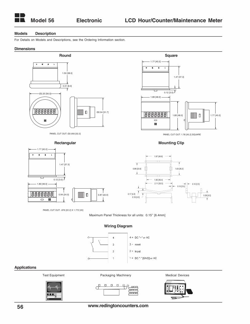
www.redingtoncounters.com
Model 56
56
Electronic LCD Hour/Counter/Maintenance Meter
Dimensions
1.77 [45.0]
1.47 [37.3]
0.12 [3.0]
1.89 [48.0]
1.89 [48.0] 1.77 [45.0]
PANEL CUT OUT: 1.78 [45.2] SQUARE
1.77 [45.0]
1.47 [37.3]
0.12 [3.0]
0.94 [24.0]
1.89 [48.0]
0.87 [22.0]
PANEL CUT OUT: .876 [22.2] X 1.772 [45]
0.31 [8.0]
1.50 [38.0]
Ø2.20 [56.0]
Ø2.04 [51.7]
PANEL CUT OUT: Ø2.055 [52.2]
0.10 [2.5]
0.38 [9.5]0.18 [4.5]
0.17 [4.3]
0.89 [22.6] 1.03 [26.2]
1.97 [49.9]
1.83 [46.4]
2.11 [53.5]0.10 [2.5]
Rectangular
SquareRound
Mounting Clip
For Details on Models and Descriptions, see the Ordering Information section.
Models Description
Medical DevicesPackaging MachineryTest Equipment
Applications
Maximum Panel Thickness for all units: 0.15’’ [6.4mm]
Wiring Diagram
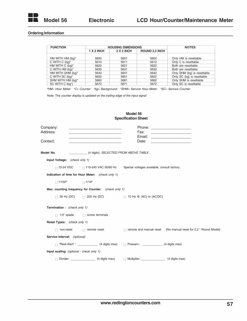
57www.redingtoncounters.com
Model 56 Electronic LCD Hour/Counter/Maintenance Meter
Ordering Information
Model 56Specification Sheet
Company: __________________________ Phone: ____________________Address: __________________________ Fax: ____________________
__________________________ Email: ____________________Contact: __________________________ Date: ____________________
Model No. ___________ (4 digits) SELECTED FROM ABOVE TABLE .
Input Voltage: (check only 1)
12-24 VDC 115-240 VAC 50/60 Hz Special voltages available, consult factory.
Indication of time for Hour Meter: (check only 1)
1/100th 1/10th
Max. counting frequency for Counter: (check only 1)
30 Hz (DC) 200 Hz (DC) 10 Hz @ (AC) or (AC/DC)
Termination : (check only 1)
1/4” spade screw terminals
Reset Types: (check only 1)
non-reset remote reset remote and manual reset (No manual reset for 2.2 “ Round Model)
Service Interval: (optional)
“Redi-Alert” : (4 digits max) Prewarn : (4 digits max)
Input scaling: (optional - check only 1)
Divider: (4 digits max) Multiplier: (4 digits max)
Note: The counter display is updated on the trailing edge of the input signal
FUNCTION HOUSING DIMENSIONS NOTES1 X 2 INCH 2 X 2 INCH ROUND 2.2 INCH
HM WITH HM (bg)* 5600 5601 5602 Only HM is resettable C WITH C (bg)* 5610 5611 5612 Only C is resettable HM WITH C (bg)* 5620 5621 5622 Both are resettable C WITH HM (bg)* 5630 5631 5632 Both are resettable HM WITH SHM (bg)* 5640 5641 5642 Only SHM (bg) is resettable C WITH SC (bg)* 5650 5651 5652 Only SC (bg) is resettable SHM WITH HM (bg)* 5660 5661 5662 Only SHM is resettable SC WITH C (bg*) 5670 5671 5672 Only SC is resettable
*HM= Hour Meter *C= Counter *bg= Background *SHM= Service Hour Meter *SC= Service Counter
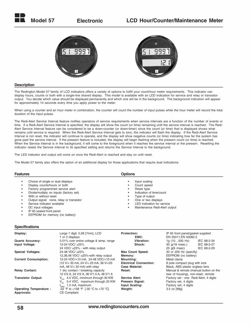
www.redingtoncounters.com
Model 57
58
Electronic LCD Hour/Counter/Maintenance Meter
The Redington Model 57 family of LCD indicators offers a variety of options to fulfill your count/hour meter requirements. This indicator candisplay hours, counts or both with a single-line shared display. This model is available with an LED indication for service and relay or transistoroutput. You decide which value should be displayed permanently and which one will be in the background. The background indication will appearfor approximately 10 seconds every time you apply power to the meter.
When using a counter and an hour meter in combination, the counter will count the number of input pulses while the hour meter will record the totalduration of the input pulses.
The Redi-Alert Service Interval feature notifies operators of service requirements when service intervals are a function of the number of events ortime. If a Redi-Alert Service Interval is specified, the display will show the count (or time) remaining until the service interval is reached. The Redi-Alert Service Interval feature can be considered to be a down-counter (or down-timer) since the count (or time) that is displayed shows whatremains until service is required. When the Redi-Alert Service Interval gets to zero, the indicator will flash the display. If the Redi-Alert ServiceInterval is not reset, the indicator will continue to operate, and the display will show negative counts (or time) indicating how far the system hasgone past the service interval. If the prewarn feature is included, the display will begin flashing when the prewarn count (or time) is reached.When the Service Interval is in the background, it will come to the foreground when it reaches the service interval or the prewarn. Resetting theindicator resets the Service Interval to its specified setting and returns the Service Interval to the background.
The LED indicator and output will come on once the Redi-Alert is reached and stay on until reset.
The Model 57 family also offers the option of an additional display for those applications that require dual indications.
• Choice of single or dual displays• Display counts/hours or both• Factory programmed service alert• Divide/multiply on inputs (factory set)• With or without reset• Output signal: none, relay or transistor• Service indicator available• DC input voltages• IP 65 sealed front panel• EEPROM for memory (no battery)
• Input scaling• Count speed• Reset type• Indication of time/count• Type of output• One or two displays• LED indication for service• Maintenance Redi-Alert output
Features Options
Description
Display: Large 7 digit, 0.28 [7mm], LCD1 or 2 displays
Quartz Accuracy: 0.01% over entire voltage & temp. rangeInput Voltage: 12-24 VDC/ ±25%
24 VDC/ ±25% - with relay outputSpecial Voltages: 24-48 VDC/ ±25%
12,36,48 VDC/ ±25%-with relay outputCurrent Consumption: 12-24 VDC/<10 mA, 24-48 VDC/<10 mA
(12 V/< 35 mA, 24 V/< 25 mA, 36 V/<25mA, 48 V/< 20 mA) with relay
Relay Contact: 1 dry contact / breaking capacity12 V/2 A, 24 V/2 A, 36 V/1.5 A, 48 V/1 A
Transistor Output: VOH 4.5 VDC, minimum through 30 KWVOL 0.4 VDC, maximum through 20 KWISINK 1.0 mA, maximum
Operating Temperature : -22 °F to +158 °F [-30 °C to +70 °C]Approvals: CE Compliant
Protection: IP 65 front panel/gasket suppliedEMC: EN 55011,EN 50082-2Vibration: 1g (10…500 Hz) IEC 68-2-34Shock: 30 g(18 msec.) IEC 68-2-27
25 g(6 msec) IEC 68-2-29Max Count Speed: 30 or 200 Hz (specify)Memory: EEPROM (no battery)Mounting: Metal clampElectrical Connection: 8 pole compact plug with lockCase Material: Black, ABS plastic w/glass lensReset: Manual & remote (manual button on the
rear of housing), non-reset, remoteService Alert: Factory set - one Redi-Alert, 4 digitsPrewarn Signal: Factory set, 4 digitsInput Scaling: Factory set, 4 digitsWeight: 3.5 oz [99g]
Specifications
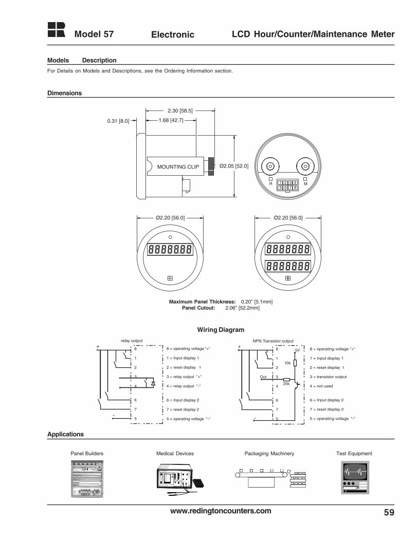
59www.redingtoncounters.com
Model 57 Electronic LCD Hour/Counter/Maintenance Meter
Ø2.20 [56.0] Ø2.20 [56.0]
0.31 [8.0] 1.68 [42.7]
2.30 [58.5]
Ø2.05 [52.0]MOUNTING CLIP
R M1 2 3 48765
Maximum Panel Thickness: 0.20” [5.1mm]Panel Cutout: 2.06” [52.2mm]
Applications
Dimensions
For Details on Models and Descriptions, see the Ordering Information section.
Models Description
Packaging MachineryPanel Builders Medical Devices Test Equipment
8
1
2
3
4
6
7
5
+
-
relay output
8
1
2
3
4
6
7
5
5V
Out
+
-
NPN Transistor output
10k
20k
8 = operating voltage "+"
1 = Input display 1
2 = reset display 1
3 = relay output "+"
4 = relay output "-"
6 = Input display 2
7 = reset display 2
5 = operating voltage "-"
8 = operating voltage "+"
1 = Input display 1
2 = reset display 1
3 = transistor output
4 = not used
6 = Input display 2
7 = reset display 2
5 = operating voltage "-"
Wiring Diagram
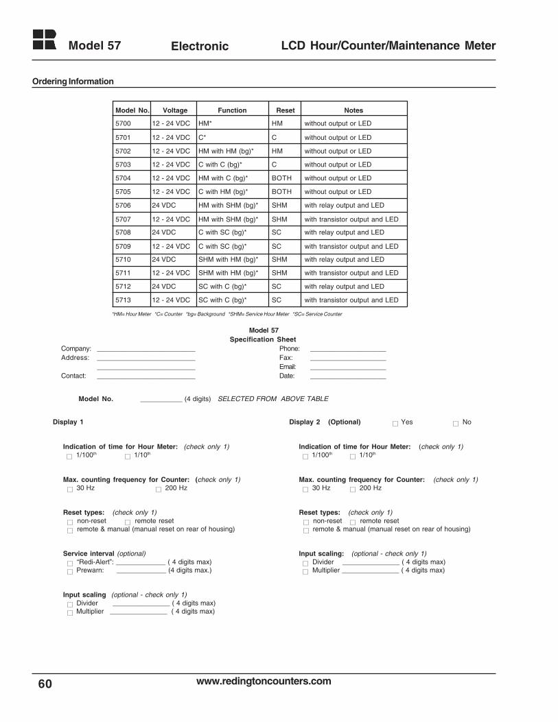
www.redingtoncounters.com
Model 57
60
Electronic LCD Hour/Counter/Maintenance Meter
Ordering Information
Display 1
Indication of time for Hour Meter: (check only 1) 1/100th 1/10th
Max. counting frequency for Counter: (check only 1) 30 Hz 200 Hz
Reset types: (check only 1) non-reset remote reset remote & manual (manual reset on rear of housing)
Service interval (optional) “Redi-Alert”: _____________ ( 4 digits max) Prewarn: _____________ (4 digits max.)
Input scaling (optional - check only 1) Divider _______________ ( 4 digits max) Multiplier _______________ ( 4 digits max)
Model No. ___________ (4 digits) SELECTED FROM ABOVE TABLE
Display 2 (Optional) Yes No
Indication of time for Hour Meter: (check only 1) 1/100th 1/10th
Max. counting frequency for Counter: (check only 1) 30 Hz 200 Hz
Reset types: (check only 1) non-reset remote reset remote & manual (manual reset on rear of housing)
Input scaling: (optional - check only 1) Divider _______________ ( 4 digits max) Multiplier _______________ ( 4 digits max)
Model 57Specification Sheet
Company: __________________________ Phone: ____________________Address: __________________________ Fax: ____________________
__________________________ Email: ____________________Contact: __________________________ Date: ____________________
*HM= Hour Meter *C= Counter *bg= Background *SHM= Service Hour Meter *SC= Service Counter
Model No. Voltage Function Reset Notes
5700 12 - 24 VDC HM* HM without output or LED
5701 12 - 24 VDC C* C without output or LED
5702 12 - 24 VDC HM with HM (bg)* HM without output or LED
5703 12 - 24 VDC C with C (bg)* C without output or LED
5704 12 - 24 VDC HM with C (bg)* BOTH without output or LED
5705 12 - 24 VDC C with HM (bg)* BOTH without output or LED
5706 24 VDC HM with SHM (bg)* SHM with relay output and LED
5707 12 - 24 VDC HM with SHM (bg)* SHM with transistor output and LED
5708 24 VDC C with SC (bg)* SC with relay output and LED
5709 12 - 24 VDC C with SC (bg)* SC with transistor output and LED
5710 24 VDC SHM with HM (bg)* SHM with relay output and LED
5711 12 - 24 VDC SHM with HM (bg)* SHM with transistor output and LED
5712 24 VDC SC with C (bg)* SC with relay output and LED
5713 12 - 24 VDC SC with C (bg)* SC with transistor output and LED
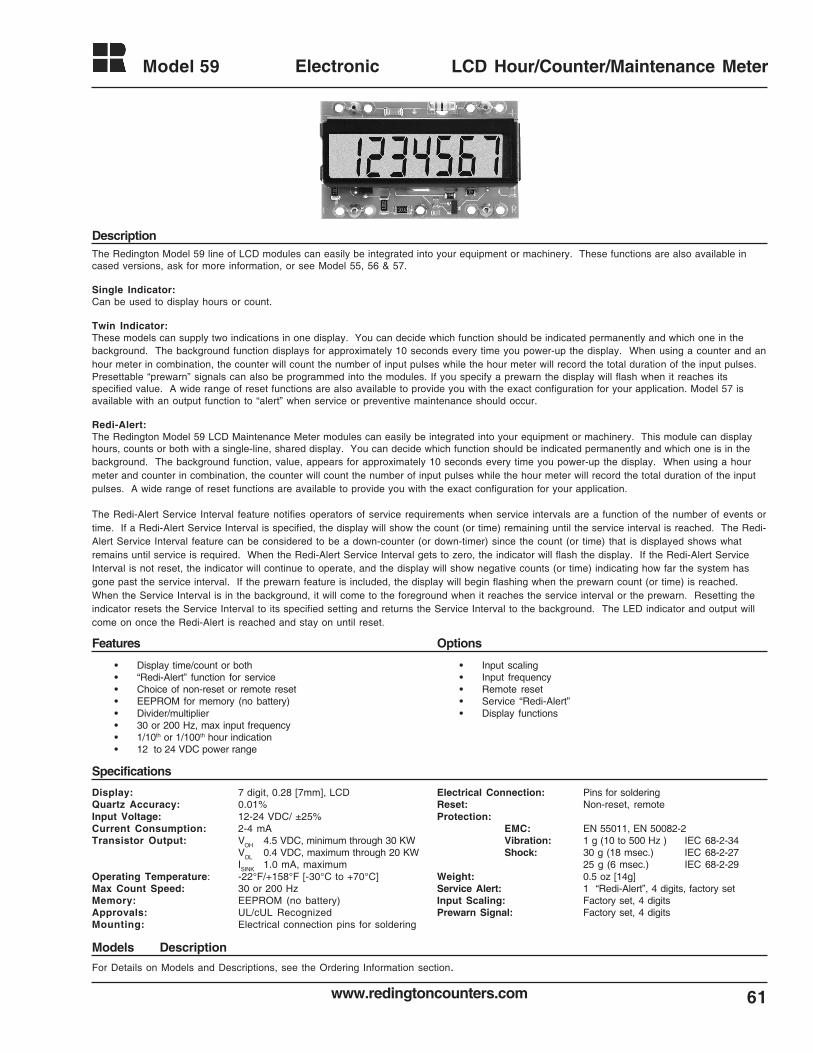
61www.redingtoncounters.com
Model 59 Electronic LCD Hour/Counter/Maintenance Meter
The Redington Model 59 line of LCD modules can easily be integrated into your equipment or machinery. These functions are also available incased versions, ask for more information, or see Model 55, 56 & 57.
Single Indicator:Can be used to display hours or count.
Twin Indicator:These models can supply two indications in one display. You can decide which function should be indicated permanently and which one in thebackground. The background function displays for approximately 10 seconds every time you power-up the display. When using a counter and anhour meter in combination, the counter will count the number of input pulses while the hour meter will record the total duration of the input pulses.Presettable “prewarn” signals can also be programmed into the modules. If you specify a prewarn the display will flash when it reaches itsspecified value. A wide range of reset functions are also available to provide you with the exact configuration for your application. Model 57 isavailable with an output function to “alert” when service or preventive maintenance should occur.
Redi-Alert:The Redington Model 59 LCD Maintenance Meter modules can easily be integrated into your equipment or machinery. This module can displayhours, counts or both with a single-line, shared display. You can decide which function should be indicated permanently and which one is in thebackground. The background function, value, appears for approximately 10 seconds every time you power-up the display. When using a hourmeter and counter in combination, the counter will count the number of input pulses while the hour meter will record the total duration of the inputpulses. A wide range of reset functions are available to provide you with the exact configuration for your application.
The Redi-Alert Service Interval feature notifies operators of service requirements when service intervals are a function of the number of events ortime. If a Redi-Alert Service Interval is specified, the display will show the count (or time) remaining until the service interval is reached. The Redi-Alert Service Interval feature can be considered to be a down-counter (or down-timer) since the count (or time) that is displayed shows whatremains until service is required. When the Redi-Alert Service Interval gets to zero, the indicator will flash the display. If the Redi-Alert ServiceInterval is not reset, the indicator will continue to operate, and the display will show negative counts (or time) indicating how far the system hasgone past the service interval. If the prewarn feature is included, the display will begin flashing when the prewarn count (or time) is reached.When the Service Interval is in the background, it will come to the foreground when it reaches the service interval or the prewarn. Resetting theindicator resets the Service Interval to its specified setting and returns the Service Interval to the background. The LED indicator and output willcome on once the Redi-Alert is reached and stay on until reset.
• Display time/count or both• “Redi-Alert” function for service• Choice of non-reset or remote reset• EEPROM for memory (no battery)• Divider/multiplier• 30 or 200 Hz, max input frequency• 1/10th or 1/100th hour indication• 12 to 24 VDC power range
• Input scaling• Input frequency• Remote reset• Service “Redi-Alert”• Display functions
Features Options
Description
Display: 7 digit, 0.28 [7mm], LCDQuartz Accuracy: 0.01%Input Voltage: 12-24 VDC/ ±25%Current Consumption: 2-4 mATransistor Output: VOH 4.5 VDC, minimum through 30 KW
VOL 0.4 VDC, maximum through 20 KWISINK 1.0 mA, maximum
Operating Temperature: -22°F/+158°F [-30°C to +70°C]Max Count Speed: 30 or 200 HzMemory: EEPROM (no battery)Approvals: UL/cUL RecognizedMounting: Electrical connection pins for soldering
Electrical Connection: Pins for solderingReset: Non-reset, remoteProtection:
EMC: EN 55011, EN 50082-2Vibration: 1 g (10 to 500 Hz ) IEC 68-2-34Shock: 30 g (18 msec.) IEC 68-2-27
25 g (6 msec.) IEC 68-2-29Weight: 0.5 oz [14g]Service Alert: 1 “Redi-Alert”, 4 digits, factory setInput Scaling: Factory set, 4 digitsPrewarn Signal: Factory set, 4 digits
Specifications
For Details on Models and Descriptions, see the Ordering Information section.
Models Description
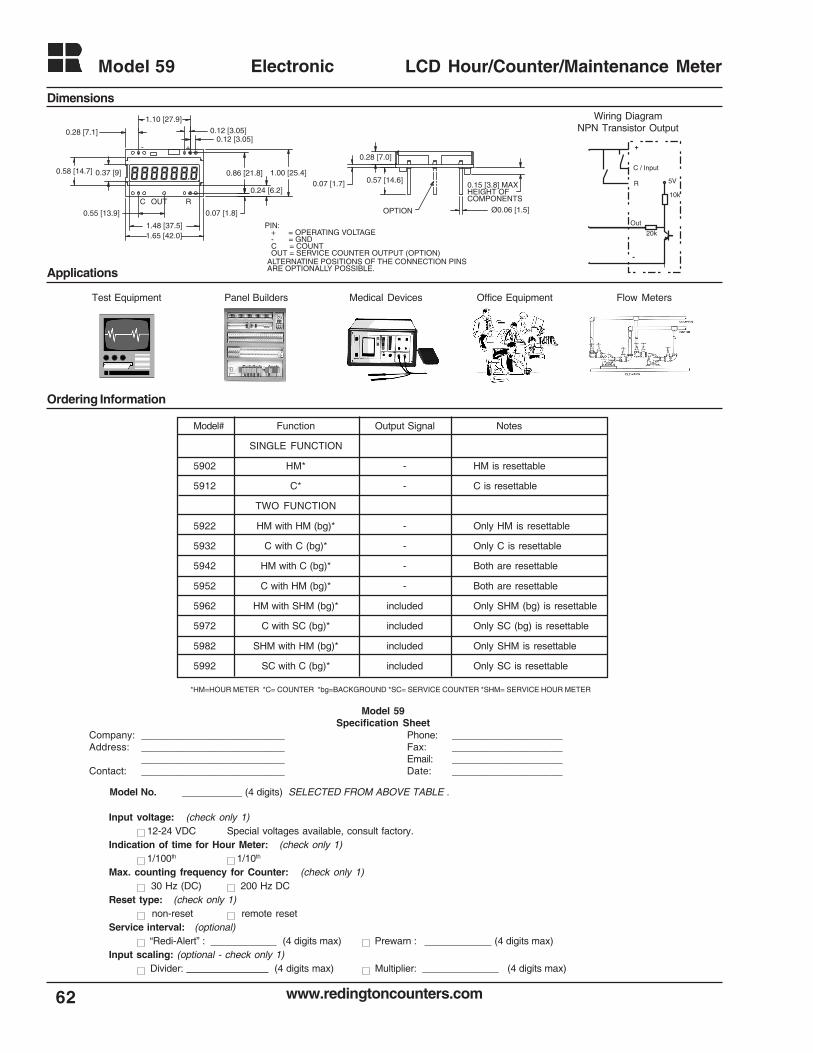
www.redingtoncounters.com
Model 59
62
Electronic LCD Hour/Counter/Maintenance Meter
0.28 [7.1]
1.10 [27.9]
1.65 [42.0]
0.07 [1.8]
1.00 [25.4]0.86 [21.8]
0.24 [6.2]
0.12 [3.05]
0.55 [13.9]
1.48 [37.5]
0.37 [9]0.58 [14.7]
- +
0.12 [3.05]
C OUT
0.28 [7.0]
0.07 [1.7] 0.57 [14.6]0.15 [3.8] MAXHEIGHT OFCOMPONENTS
Ø0.06 [1.5]OPTION
PIN: + = OPERATING VOLTAGE - = GND C = COUNT OUT = SERVICE COUNTER OUTPUT (OPTION)ALTERNATINE POSITIONS OF THE CONNECTION PINSARE OPTIONALLY POSSIBLE.
R
*HM=HOUR METER *C= COUNTER *bg=BACKGROUND *SC= SERVICE COUNTER *SHM= SERVICE HOUR METER
Model No. ___________ (4 digits) SELECTED FROM ABOVE TABLE .
Input voltage: (check only 1) 12-24 VDC Special voltages available, consult factory.
Indication of time for Hour Meter: (check only 1) 1/100th 1/10th
Max. counting frequency for Counter: (check only 1) 30 Hz (DC) 200 Hz DC
Reset type: (check only 1) non-reset remote reset
Service interval: (optional) “Redi-Alert” : (4 digits max) Prewarn : (4 digits max)
Input scaling: (optional - check only 1) Divider: _______________ (4 digits max) Multiplier: ______________ (4 digits max)
Dimensions
Applications
Ordering Information
Model 59Specification Sheet
Company: __________________________ Phone: ____________________Address: __________________________ Fax: ____________________
__________________________ Email: ____________________Contact: __________________________ Date: ____________________
Medical DevicesTest Equipment Panel Builders Office Equipment Flow Meters
Output Signal
-
-
-
-
-
-
included
included
included
included
Model#
5902
5912
5922
5932
5942
5952
5962
5972
5982
5992
Function
SINGLE FUNCTION
HM*
C*
TWO FUNCTION
HM with HM (bg)*
C with C (bg)*
HM with C (bg)*
C with HM (bg)*
HM with SHM (bg)*
C with SC (bg)*
SHM with HM (bg)*
SC with C (bg)*
Notes
HM is resettable
C is resettable
Only HM is resettable
Only C is resettable
Both are resettable
Both are resettable
Only SHM (bg) is resettable
Only SC (bg) is resettable
Only SHM is resettable
Only SC is resettable
5V
Out
20k
10k
+
-
C / Input
R
Wiring DiagramNPN Transistor Output
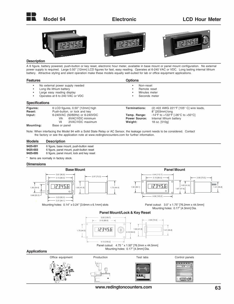
63www.redingtoncounters.com
Model 94 Electronic LCD Hour Meter
A 6 figure, battery powered, push-button or key reset, electronic hour meter, available in base mount or panel mount configuration. No externalpower supply is required. Large 0.50’’ [12mm] LCD figures for fast, easy reading. Operates at 6-240 VAC or VDC. Long lasting internal lithiumbattery. Attractive styling and silent operation make these models equally well-suited for lab or office equipment applications.
Figures: 6 LCD figures, 0.50’’ [12mm] highReset: Push-button, or lock and keyInput: 6-240VAC (50/60Hz) or 6-240VDC
Vih 6VAC/VDC minimumVil 2VAC/VDC maximum
Mounting: Base or panel
9425-001 6 figure, base mount, push-button reset9425-003 6 figure, panel mount, push-button reset9425-005 6 figure, panel mount, lock and key reset
* Items are normally in factory stock.
Applications
Dimensions
Models Description
Description
Features Options
Specifications
• Non-reset• Remote reset• Minutes meter• Seconds meter
• No external power supply needed• Long life lithium battery• Large easy reading display• Operates at 6 to 240 VAC or VDC
Office equipment Production Test labs Control panels
Terminations: (2) #22 AWG 221°F [105° C] wire leads,8’’ [203mm] long
Temp. Range: -14°F to +122°F [-26°C to +50°C]Power Source: Internal lithium batteryWeight: 18 oz. [510g]
Base Mount Panel Mount
Mounting holes: 0.14’’ x 0.24’’ [3.6mm x 6.1mm] slots Panel cutout: 3.0’’ x 1.75” [76.2mm x 44.5mm]Mounting holes: 0.17’’ [4.3mm] Dia.
1.75 [44.4]
2.97 [75.3]
1.65 [41.9]
3.15 [80.0]
3.81 [96.8]
3.23 [82.0]
3.31 [84.1]
0.88 [22.2]
1.36 [34.4]1.87 [47.6]
1.50 [38.1]
4.06 [103.2]
3.15 [80.0]
4.44 [112.7]
1.65 [41.9]
2.90 [73.5]
1.41 [35.8]
Panel Mount/Lock & Key Reset
1.41 [35.8]
2.90 [73.5]3.15 [80.0]
5.50 [139.7]
2.12 [54.0]
1.65 [41.9]1.75 [44.5]
5.13 [130.2]
Panel cutout: 4.75 ’’ x 1.50” [76.2mm x 44.5mm]Mounting holes: 0.17’’ [4.3mm] Dia.
Note: When interfacing the Model 94 with a Solid State Relay or AC Sensor, the leakage current needs to be considered. Contactthe factory or see the application note at www.redingtoncounters.com for further information.

www.redingtoncounters.com
Model 720 Electronic
64
LCD Hour Meter
Description
Features Options
Specifications
Dimensions
Applications
The Redington Model 720 Electronic Hour Meter offers a large 7 digit LCD display, (999999.9) 0.32" (8mm) high, with an input operating voltageof 85-500VAC. The front of the unit is totally sealed, and the Hour Meter is housed in a rugged steel enclosure that is interchangeable with theRedington Model 720 Electro Mechanical Hour Meters. The wide operating voltage makes this product ideal for almost any application.
• Gasket (721-0004)• Special termination available• DC
Display: Large 7 digit LCD (999999.9), 0.32" [8mm] highReset: Non-resetVoltage: 85-500VAC 50/60HzHour Meter Memory: Self-powered (internal lithium battery)Termination: Wire leads 6" [152mm]Mounting: Panel (3-Hole)Temp. Range:
Operating: -4°F to + 140°F(-20°C to +60°C)Storage: -40°F to +165°F (-40°C to +75°C)
Humidity: 0 to 95% RH, non-condensing,front totally sealed
Vibration: 10 to 80 Hz, 0.06 double amplitudeShock: 50GDielectric: 1000VAC 50/60Hz for 1 minuteAccuracy: Quartz accuracy (better than 0.01%)Weight: 5.0 oz (142g)
720-5300 85-500VAC, non-reset, 3-hole round, 6" (152mm) wire leads* Item is normally in factory stock.
720-5300
Panel cutout: 2.16’’ [54.9] Dia.Mounting holes: 0.125’’ [3.2] Dia. on 2.44’’ [62.0] B.C.
• Operating voltage 85-500VAC• Rugged steel housing• Lithium battery• Quartz accuracy (better than 0.01%)• Popular 3-hole mounting
Control panels Outdoor Lighting Test equipment
Models Description
2.37 [60.2]
Ø2.14 [54.2]
Ø2.66 [67.5]
3X Ø.125 [Ø3.2] EQUALLY SPACEDON A 2.44[62.0] B.C.
6 IN. LEADS
Industrial Equipment Compressors
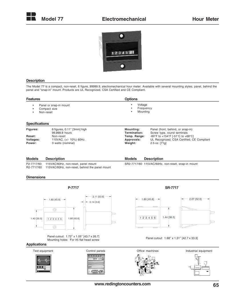
65www.redingtoncounters.com
Model 77 Electromechanical Hour Meter
Description
Features Options
Specifications
Models DescriptionModels Description
Dimensions
Applications
P-7717
The Model 77 is a compact, non-reset, 6 figure, 99999.9, electromechanical hour meter. Available with several mounting styles, panel, behind thepanel and “snap-in” mount. Products are UL Recognized, CSA Certified and CE Compliant.
Figures: 6 figures, 0.11’’ [3mm] high99,999.9 hours
Reset: Non-resetVoltages: 115VAC, (+/- 10%) 60Hz.Power: 3 watts (nominal)
• Voltage• Frequency• Mounting
Mounting: Panel (front, behind, or snap-in)Termination: Screw type, round terminalsTemp. Range: -60°F to +154°F [-51°C to +68°C]Approvals: UL Recognized, CSA Certified, CE CompliantWeight: 2.5 oz. [71g]
P2-7717/60 115VAC/60Hz, non-reset, panel mountR2-7717/60 115VAC/60Hz, non-reset, behind the panel mount
SR2-7717/60 115VAC/60Hz, non-reset, snap-in mount
1.80 [45.8]
1.80 [45.6]1 2 3 4 5 61.40 [35.5]
0.14 [3.6]
2.11 [53.6]
1 2 3 4 5 6 1.44 [36.5]
1.80 [45.8] 2.07 [52.6]
SR-7717
Panel cutout: 1.72’’ x 1.05’’ [43.7 x 26.7]Mounting holes: For #5 flat head screw
Panel cutout: 1.68’’ x 1.31’’ [42.7 x 33.3]
• Panel or snap-in mount• Compact size• Non-reset
Test equipment Control panels Office machines Industrial equipment
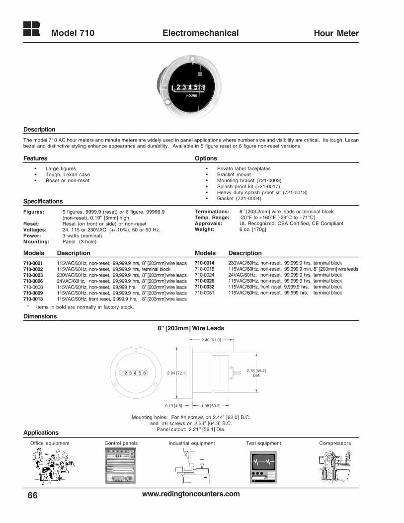
www.redingtoncounters.com
Model 710
66
Electromechanical Hour Meter
Description
Features Options
Specifications
Models DescriptionModels Description
Dimensions
Applications
8” [203mm] Wire Leads
The model 710 AC hour meters and minute meters are widely used in panel applications where number size and visibility are critical. Its tough, Lexanbezel and distinctive styling enhance appearance and durability. Available in 5 figure reset or 6 figure non-reset versions.
Figures: 5 figures, 9999.9 (reset) or 6 figure, 99999.9(non-reset), 0.19’’ [5mm] high
Reset: Reset (on front or side) or non-resetVoltages: 24, 115 or 230VAC, (+/-10%), 50 or 60 Hz.Power: 3 watts (nominal)Mounting: Panel (3-hole)
Terminations: 8’’ [203.2mm] wire leads or terminal blockTemp. Range: -20°F to +160°F [-29°C to +71°C]Approvals: UL Recognized, CSA Certified, CE CompliantWeight: 6 oz. [170g]
• Private label faceplates• Bracket mount• Mounting bracet (721-0003)• Splash proof kit (721-0017)• Heavy duty splash proof kit (721-0018)• Gasket (721-0004)
710-0001 115VAC/60Hz, non-reset, 99,999.9 hrs, 8’’ [203mm] wire leads710-0002 115VAC/60Hz, non-reset, 99,999.9 hrs, terminal block710-0003 230VAC/60Hz, non-reset, 99,999.9 hrs, 8’’ [203mm] wire leads710-0006 24VAC/60Hz, non-reset, 99,999.9 hrs, 8’’ [203mm] wire leads710-0008 115VAC/60Hz, non-reset, 99,999 hrs, 8’’ [203mm] wire leads710-0009 115VAC/50Hz, non-reset, 99,999.9 hrs, 8’’ [203mm] wire leads710-0013 115VAC/60Hz, front reset, 9,999.9 hrs, 8’’ [203mm] wire leads
1 2 3 4 5 6 2.84 [72.1]
1.98 [50.3]
2.40 [61.0]
2.18 [55.2]DIA
0.19 [4.8]
Mounting holes: For #4 screws on 2.44” [62.0] B.C.and #6 screws on 2.53” [64.3] B.C.
Panel cutout: 2.21’’ [56.1] Dia.
• Large figures• Tough, Lexan case• Reset or non-reset
Control panels Industrial equipment Test equipment CompressorsOffice equipment
710-0014 230VAC/60Hz, non-reset, 99,999.9 hrs, terminal block710-0018 115VAC/60Hz, non-reset, 99,999.9 min, 8’’ [203mm] wire leads710-0024 24VAC/60Hz, non-reset, 99,999.9 hrs, terminal block710-0026 115VAC/50Hz, non-reset, 99,999.9 hrs, terminal block710-0032 115VAC/60Hz, front reset, 9,999.9 hrs, terminal block710-0051 115VAC/60Hz, non-reset, 99,999 hrs, terminal block
* Items in bold are normally in factory stock.
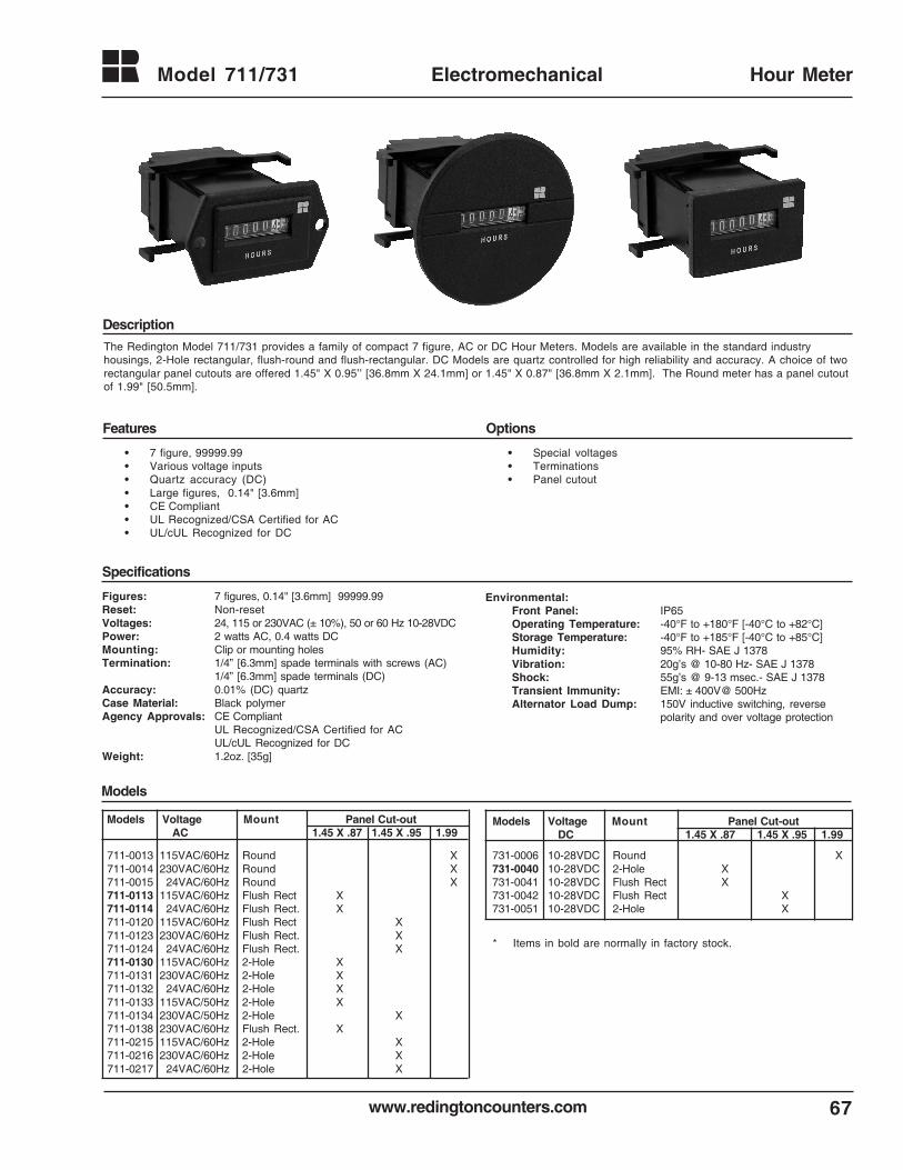
www.redingtoncounters.com 67
Model 711/731 Electromechanical Hour Meter
• 7 figure, 99999.99• Various voltage inputs• Quartz accuracy (DC)• Large figures, 0.14" [3.6mm]• CE Compliant• UL Recognized/CSA Certified for AC• UL/cUL Recognized for DC
Environmental:Front Panel: IP65Operating Temperature: -40°F to +180°F [-40°C to +82°C]Storage Temperature: -40°F to +185°F [-40°C to +85°C]Humidity: 95% RH- SAE J 1378Vibration: 20g’s @ 10-80 Hz- SAE J 1378Shock: 55g’s @ 9-13 msec.- SAE J 1378Transient Immunity: EMI: ± 400V@ 500HzAlternator Load Dump: 150V inductive switching, reverse
polarity and over voltage protection
• Special voltages• Terminations• Panel cutout
The Redington Model 711/731 provides a family of compact 7 figure, AC or DC Hour Meters. Models are available in the standard industryhousings, 2-Hole rectangular, flush-round and flush-rectangular. DC Models are quartz controlled for high reliability and accuracy. A choice of tworectangular panel cutouts are offered 1.45" X 0.95’’ [36.8mm X 24.1mm] or 1.45" X 0.87" [36.8mm X 2.1mm]. The Round meter has a panel cutoutof 1.99" [50.5mm].
Figures: 7 figures, 0.14" [3.6mm] 99999.99Reset: Non-resetVoltages: 24, 115 or 230VAC (± 10%), 50 or 60 Hz 10-28VDCPower: 2 watts AC, 0.4 watts DCMounting: Clip or mounting holesTermination: 1/4” [6.3mm] spade terminals with screws (AC)
1/4” [6.3mm] spade terminals (DC)Accuracy: 0.01% (DC) quartzCase Material: Black polymerAgency Approvals: CE Compliant
UL Recognized/CSA Certified for ACUL/cUL Recognized for DC
Weight: 1.2oz. [35g]
Models Voltage Mount Panel Cut-out AC 1.45 X .87 1.45 X .95 1.99
711-0013 115VAC/60Hz Round X 711-0014 230VAC/60Hz Round X 711-0015 24VAC/60Hz Round X 711-0113 115VAC/60Hz Flush Rect X 711-0114 24VAC/60Hz Flush Rect. X 711-0120 115VAC/60Hz Flush Rect X 711-0123 230VAC/60Hz Flush Rect. X 711-0124 24VAC/60Hz Flush Rect. X 711-0130 115VAC/60Hz 2-Hole X 711-0131 230VAC/60Hz 2-Hole X 711-0132 24VAC/60Hz 2-Hole X 711-0133 115VAC/50Hz 2-Hole X 711-0134 230VAC/50Hz 2-Hole X 711-0138 230VAC/60Hz Flush Rect. X 711-0215 115VAC/60Hz 2-Hole X 711-0216 230VAC/60Hz 2-Hole X 711-0217 24VAC/60Hz 2-Hole X
Models Voltage Mount Panel Cut-out DC 1.45 X .87 1.45 X .95 1.99
731-0006 10-28VDC Round X 731-0040 10-28VDC 2-Hole X 731-0041 10-28VDC Flush Rect X 731-0042 10-28VDC Flush Rect X 731-0051 10-28VDC 2-Hole X
Specifications
Features Options
Description
Models
* Items in bold are normally in factory stock.
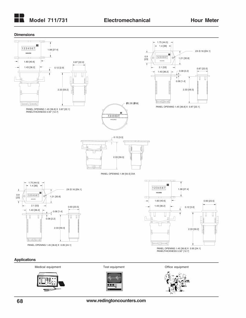
www.redingtoncounters.com
Model 711/731
68
Electromechanical Hour Meter
Dimensions
1 2 3 4 5 6 7
H O U R S
O2.28 [O58]
2.33 [59.3]
0.13 [3.3]
PANEL OPENING 1.99 [50.5] DIA
0.12 [2.9]1.43 [36.2]
1.60 [40.6]
1.08 [27.4]
2.33 [59.2]
0.87 [22.0]
PANEL OPENING 1.45 [36.8] X 0.87 [22.1]PANELTHICKNESS 0.50'' [12.7]
1 2 3 4 5 6 7
0.12 [3.0]1.43 [36.2]
1.60 [40.6]
1.08 [27.4]
2.33 [59.2]
0.93 [23.5]
PANEL OPENING 1.45 [36.8] X 0.95 [24.1]PANELTHICKNESS 0.50'' [12.7]
1 2 3 4 5 6 7
Medical equipment Office equipmentTest equipment
2X Ø.16 [Ø4.1]
1.75 [44.5]
2.1 [53]
0.9[23] 1.21 [30.8]
1.43 [36.2]
0.08 [2.2]
2.33 [59.3]
0.93 [23.5]
PANEL OPENING 1.45 [36.8] X 0.95 [24.1]
0.06 [1.4]
1.4 [36]
1 2 3 4 5 6 7
2X Ø.16 [Ø4.1]
1.75 [44.5]
2.1 [53]
1.21 [30.8]
1.43 [36.2]
2.33 [59.3]
0.08 [2.2]0.87 [22.0]
PANEL OPENING 1.45 [36.8] X 0.87 [22.1]
0.06 [1.4]
0.9[23]
1.4 [36]
1 2 3 4 5 6 7
Applications
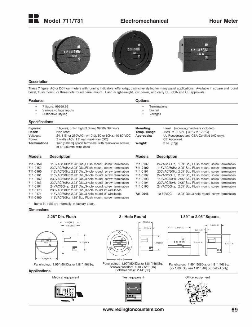
www.redingtoncounters.com 69
Model 711/731 Electromechanical Hour Meter
These 7 figure, AC or DC hour meters with running indicators, offer crisp, distinctive styling for many panel applications. Available in square and roundbezel, flush mount, or three-hole round panel mount. Each is light-weight, low power, and carry UL, CSA and CE approvals.
Specifications
Features Options
Description
Figures: 7 figures, 0.14’’ high [3.6mm], 99,999.99 hoursReset: Non-resetVoltages: 24, 115, or 230VAC (+/-10%), 50 or 60Hz., 10-80 VDCPower: 3 watts (AC), 1.2 watt maximum (DC)Terminations: 1/4’’ [6.3mm] spade terminals, with removable screws,
or 8’’ [203mm] wire leads
• Terminations• Din rail• Voltages
Mounting: Panel (mounting hardware included)Temp. Range: -22°F to +158°F [-30°C to +70°C]Approvals: UL Recognized and CSA Certified (AC only),
CE ApprovedWeight: 2 oz. [57g]
711-0150 115VAC/60Hz, 2.28’’ Dia.,Flush mount, screw termination711-0152 230VAC/60Hz, 2.28’’ Dia.,Flush mount, screw termination711-0160 115VAC/60Hz, 2.93’’ Dia.,3-hole round, screw termination711-0161 115VAC/50Hz, 2.93’’ Dia.,3-hole round, screw termination711-0162 230VAC/60Hz, 2.93’’ Dia.,3-hole round, screw termination711-0163 230VAC/50Hz, 2.93’’ Dia.,3-hole round, screw termination711-0164 24VAC/60Hz, 2.93’’ Dia.,3-hole round, screw termination711-0170 230VAC/60Hz, 2.93’’ Dia.,3-hole round, 8’’ wire leads711-0171 115VAC/60Hz, 2.93’’ Dia.,3-hole round, 8’’ wire leads711-0180 115VAC/60Hz, 1.89’’ Sq., Flush mount, screw termination
Models DescriptionModels Description
711-0182 24VAC/60Hz, 1.89’’ Sq., Flush mount, screw termination711-0190 115VAC/60Hz, 2.05’’ Sq., Flush mount, screw termination711-0191 230VAC/60Hz, 2.05’’ Sq., Flush mount, screw termination711-0192 24VAC/60Hz, 2.05’’ Sq., Flush mount, screw termination711-0193 115VAC/50Hz, 2.05’’ Sq., Flush mount, screw termination711-0194 230VAC/50Hz, 2.05’’ Sq., Flush mount, screw termination711-0195 24VAC/50Hz, 2.05’’ Sq., Flush mount, screw termination
731-0046 10-80VDC, 2.93’’ Dia.,3-hole round, screw termination
Dimensions
Applications
1.35 [34.3]
1.77 [44.9]
2.28 [57.9]
1.55 [39.3]
2.20 [55.9]0.20 [5.1]
2.20 [55.9]1.77 [44.9]
1.35 [34.3]
1.35 [34.3]
1.60 [40.6]
1.77 [44.9]
2.93 [74.5]
2.28’’ Dia. Flush 3 - Hole Round 1.89’’ or 2.05’’ Square
Panel cutout: 1.99’’ [50] Dia. or 1.81’’ [46] Sq.(for 1.89’’ Sq. use 1.81’’ [46] Sq. cutout only)
Panel cutout: 1.99’’ [50] Dia. or 1.81’’ [46] Sq. Panel cutout: 1.99’’ [50] Dia. or 1.81’’ [46] Sq.Screws provided: 4-40 x 5/8’’ [16]
Bolt hole circle: 2.44’’ [62]
Medical equipment Office equipmentTest equipment
• 7 figure, 99999.99• Various voltage inputs• Distinctive styling
* Items in bold are normally in factory stock.
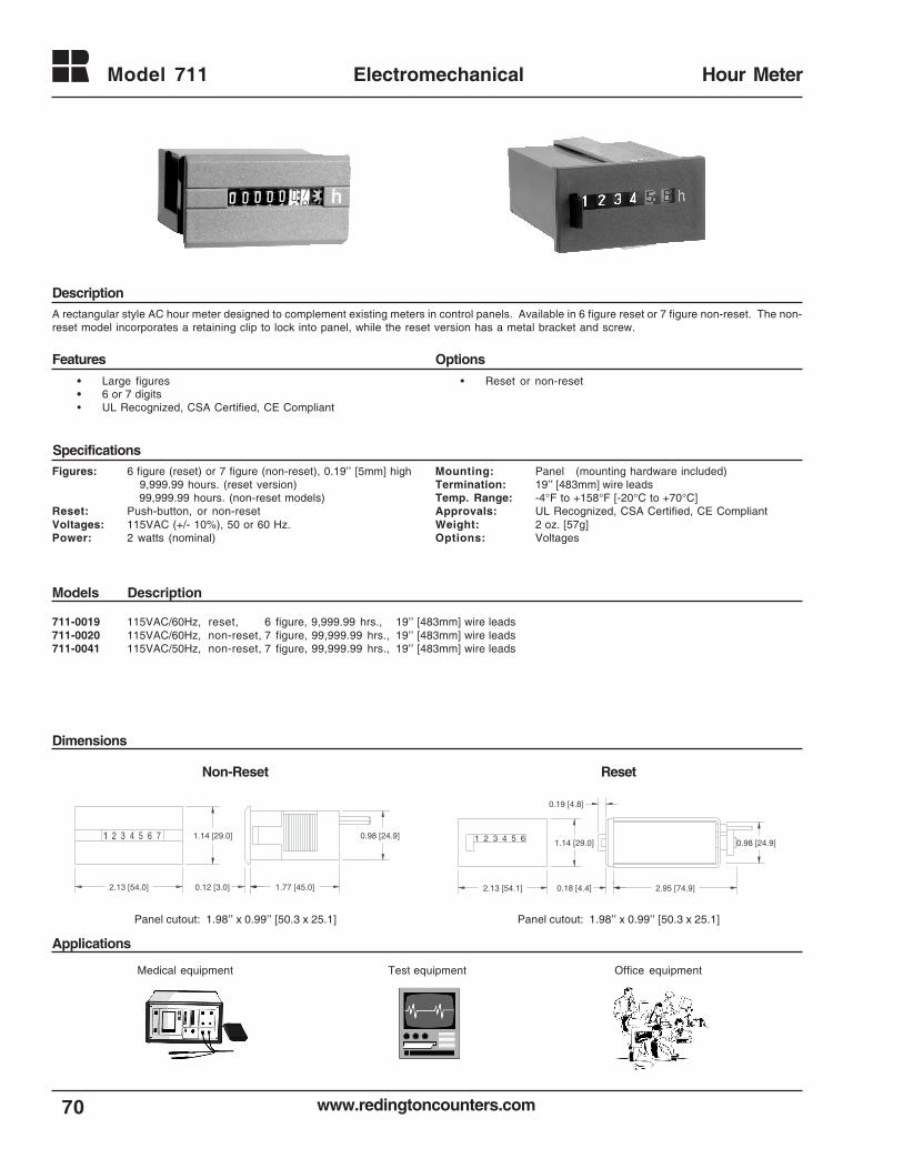
www.redingtoncounters.com70
Model 711 Electromechanical Hour Meter
A rectangular style AC hour meter designed to complement existing meters in control panels. Available in 6 figure reset or 7 figure non-reset. The non-reset model incorporates a retaining clip to lock into panel, while the reset version has a metal bracket and screw.
Specifications
Features Options
Description
• Reset or non-reset
Models Description
Dimensions
Applications
Medical equipment Office equipmentTest equipment
Figures: 6 figure (reset) or 7 figure (non-reset), 0.19’’ [5mm] high 9,999.99 hours. (reset version) 99,999.99 hours. (non-reset models)
Reset: Push-button, or non-resetVoltages: 115VAC (+/- 10%), 50 or 60 Hz.Power: 2 watts (nominal)
Mounting: Panel (mounting hardware included)Termination: 19’’ [483mm] wire leadsTemp. Range: -4°F to +158°F [-20°C to +70°C]Approvals: UL Recognized, CSA Certified, CE CompliantWeight: 2 oz. [57g]Options: Voltages
711-0019 115VAC/60Hz, reset, 6 figure, 9,999.99 hrs., 19’’ [483mm] wire leads711-0020 115VAC/60Hz, non-reset, 7 figure, 99,999.99 hrs., 19’’ [483mm] wire leads711-0041 115VAC/50Hz, non-reset, 7 figure, 99,999.99 hrs., 19’’ [483mm] wire leads
1 2 3 4 5 6 7
2.13 [54.0]
1.14 [29.0]
1.77 [45.0]
0.98 [24.9]
0.12 [3.0]
Non-Reset
• Large figures• 6 or 7 digits• UL Recognized, CSA Certified, CE Compliant
Panel cutout: 1.98’’ x 0.99’’ [50.3 x 25.1] Panel cutout: 1.98’’ x 0.99’’ [50.3 x 25.1]
1 2 3 4 5 6
2.13 [54.1]
1.14 [29.0]
2.95 [74.9]
0.98 [24.9]
0.18 [4.4]
0.19 [4.8]
Reset
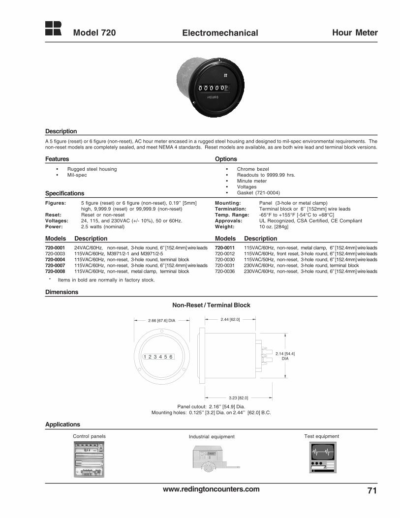
71www.redingtoncounters.com
Model 720 Electromechanical Hour Meter
Description
Features Options
Specifications
Models DescriptionModels Description
Dimensions
Applications
A 5 figure (reset) or 6 figure (non-reset), AC hour meter encased in a rugged steel housing and designed to mil-spec environmental requirements. Thenon-reset models are completely sealed, and meet NEMA 4 standards. Reset models are available, as are both wire lead and terminal block versions.
• Chrome bezel• Readouts to 9999.99 hrs.• Minute meter• Voltages• Gasket (721-0004)
Figures: 5 figure (reset) or 6 figure (non-reset), 0.19’’ [5mm]high, 9,999.9 (reset) or 99,999.9 (non-reset)
Reset: Reset or non-resetVoltages: 24, 115, and 230VAC (+/- 10%), 50 or 60Hz.Power: 2.5 watts (nominal)
Mounting: Panel (3-hole or metal clamp)Termination: Terminal block or 6’’ [152mm] wire leadsTemp. Range: -65°F to +155°F [-54°C to +68°C]Approvals: UL Recognized, CSA Certified, CE CompliantWeight: 10 oz. [284g]
720-0001 24VAC/60Hz, non-reset, 3-hole round, 6’’ [152.4mm] wire leads720-0003 115VAC/60Hz, M3971/2-1 and M3971/2-5720-0004 115VAC/60Hz, non-reset, 3-hole round, terminal block720-0007 115VAC/60Hz, non-reset, 3-hole round, 6’’ [152.4mm] wire leads720-0008 115VAC/60Hz, non-reset, metal clamp, terminal block
720-0011 115VAC/60Hz, non-reset, metal clamp, 6’’ [152.4mm] wire leads720-0012 115VAC/60Hz, front reset, 3-hole round, 6’’ [152.4mm] wire leads720-0030 115VAC/50Hz, non-reset, 3-hole round, 6’’ [152.4mm] wire leads720-0031 230VAC/60Hz, non-reset, 3-hole round, terminal block720-0036 230VAC/60Hz, non-reset, 3-hole round, 6’’ [152.4mm] wire leads
Non-Reset / Terminal Block
2.44 [62.0]
3.23 [82.0]
2.66 [67.6] DIA
1 2 3 4 5 62.14 [54.4]
DIA
Panel cutout: 2.16’’ [54.9] Dia.Mounting holes: 0.125’’ [3.2] Dia. on 2.44’’ [62.0] B.C.
• Rugged steel housing• Mil-spec
Control panels Industrial equipment Test equipment
* Items in bold are normally in factory stock.
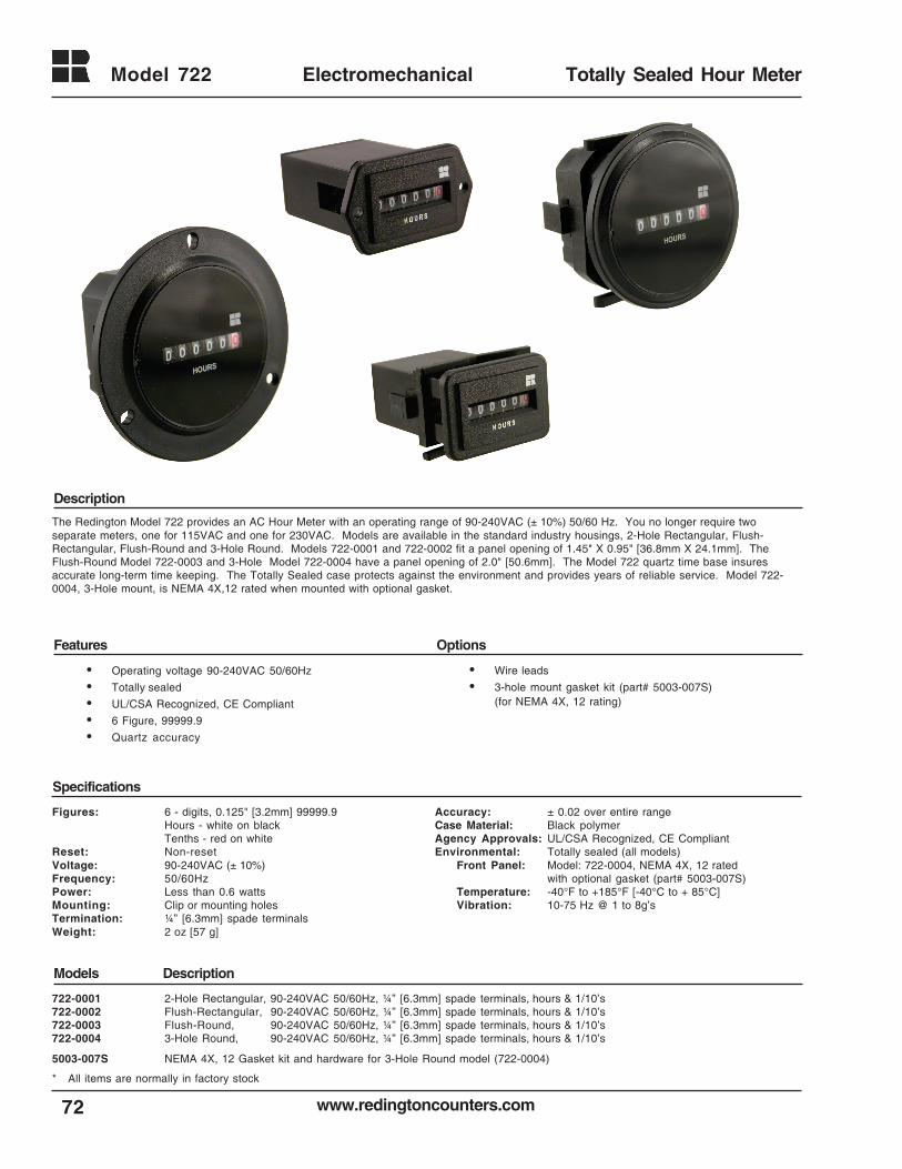
www.redingtoncounters.com
Model 722
72
Electromechanical Totally Sealed Hour Meter
722-0001 2-Hole Rectangular, 90-240VAC 50/60Hz, ¼” [6.3mm] spade terminals, hours & 1/10’s722-0002 Flush-Rectangular, 90-240VAC 50/60Hz, ¼” [6.3mm] spade terminals, hours & 1/10’s722-0003 Flush-Round, 90-240VAC 50/60Hz, ¼” [6.3mm] spade terminals, hours & 1/10’s722-0004 3-Hole Round, 90-240VAC 50/60Hz, ¼” [6.3mm] spade terminals, hours & 1/10’s
5003-007S NEMA 4X, 12 Gasket kit and hardware for 3-Hole Round model (722-0004)
* All items are normally in factory stock
Models Description
Specifications
Features Options
Description
The Redington Model 722 provides an AC Hour Meter with an operating range of 90-240VAC (± 10%) 50/60 Hz. You no longer require twoseparate meters, one for 115VAC and one for 230VAC. Models are available in the standard industry housings, 2-Hole Rectangular, Flush-Rectangular, Flush-Round and 3-Hole Round. Models 722-0001 and 722-0002 fit a panel opening of 1.45" X 0.95" [36.8mm X 24.1mm]. TheFlush-Round Model 722-0003 and 3-Hole Model 722-0004 have a panel opening of 2.0" [50.6mm]. The Model 722 quartz time base insuresaccurate long-term time keeping. The Totally Sealed case protects against the environment and provides years of reliable service. Model 722-0004, 3-Hole mount, is NEMA 4X,12 rated when mounted with optional gasket.
• Operating voltage 90-240VAC 50/60Hz
• Totally sealed
• UL/CSA Recognized, CE Compliant
• 6 Figure, 99999.9
• Quartz accuracy
• Wire leads
• 3-hole mount gasket kit (part# 5003-007S)(for NEMA 4X, 12 rating)
Figures: 6 - digits, 0.125" [3.2mm] 99999.9Hours - white on blackTenths - red on white
Reset: Non-resetVoltage: 90-240VAC (± 10%)Frequency: 50/60HzPower: Less than 0.6 wattsMounting: Clip or mounting holesTermination: ¼” [6.3mm] spade terminalsWeight: 2 oz [57 g]
Accuracy: ± 0.02 over entire rangeCase Material: Black polymerAgency Approvals: UL/CSA Recognized, CE CompliantEnvironmental: Totally sealed (all models)
Front Panel: Model: 722-0004, NEMA 4X, 12 ratedwith optional gasket (part# 5003-007S)
Temperature: -40°F to +185°F [-40°C to + 85°C]Vibration: 10-75 Hz @ 1 to 8g’s
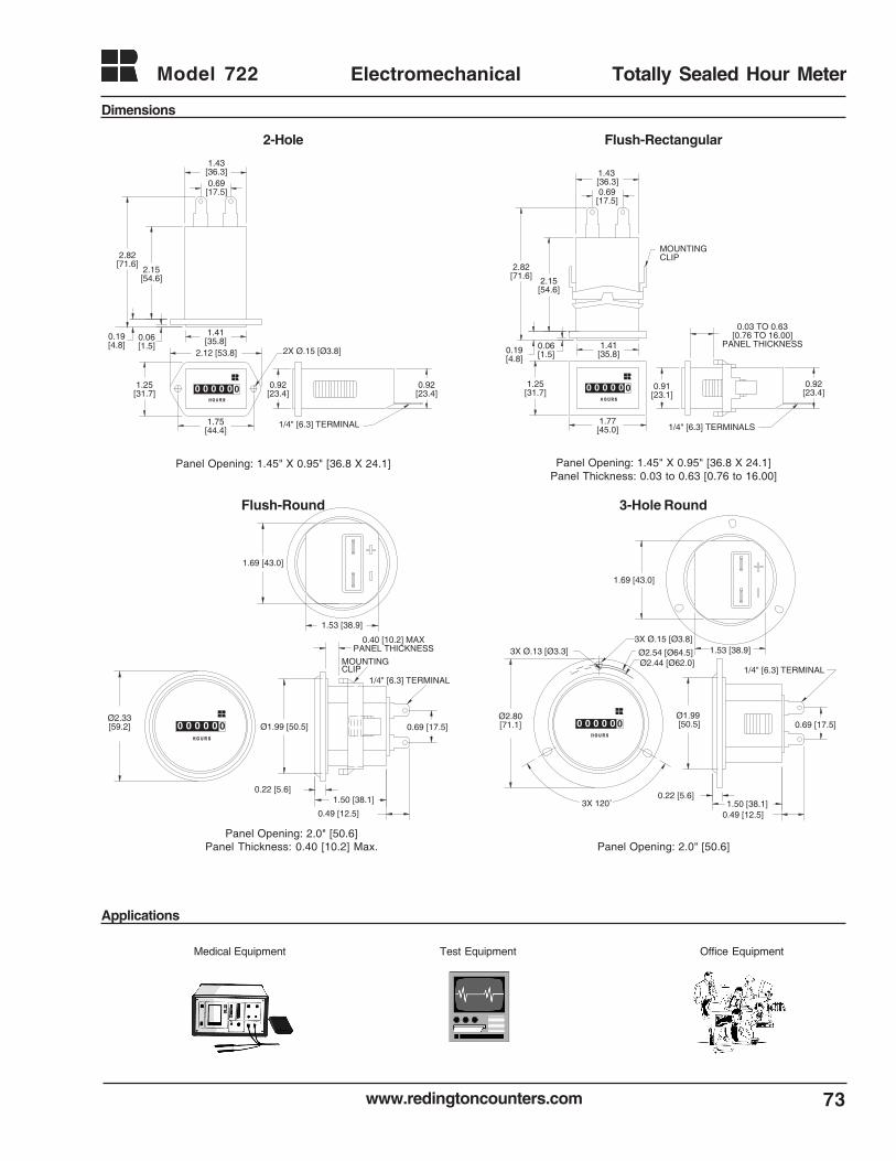
www.redingtoncounters.com 73
Model 722 Electromechanical Totally Sealed Hour Meter
Applications
0.03 TO 0.63[0.76 TO 16.00]
PANEL THICKNESS
0.92[23.4]
1/4" [6.3] TERMINALS
2.15[54.6]
2.82[71.6]
1.77[45.0]
1.41[35.8]0.19
[4.8]
1.25[31.7]
0.06[1.5]
0.91[23.1]
0.69[17.5]
1.43 [36.3]
MOUNTING CLIP
0 0 0 0 00 0 0 0 0 0
Dimensions
0.92[23.4]
1/4" [6.3] TERMINAL
2.15[54.6]
2.82[71.6]
1.75[44.4]
2.12 [53.8]
1.41[35.8]0.19
[4.8]
1.25[31.7]
0.06[1.5]
2X Ø.15 [Ø3.8]
0.92[23.4]
1.43[36.3]0.69[17.5]
0 0 0 0 0
0 0 0 0 00 0 0 0 0 0
Medical Equipment Test Equipment Office Equipment
0.49 [12.5]
1/4" [6.3] TERMINAL
0.40 [10.2] MAXPANEL THICKNESS
Ø2.33[59.2] Ø1.99 [50.5]
0.22 [5.6]1.50 [38.1]
1.53 [38.9]
1.69 [43.0]
0.69 [17.5]
MOUNTINGCLIP
0 0 0 0 00 0 0 0 0 0
Panel Opening: 2.0" [50.6]Panel Thickness: 0.40 [10.2] Max. Panel Opening: 2.0" [50.6]
Panel Opening: 1.45" X 0.95" [36.8 X 24.1] Panel Opening: 1.45" X 0.95" [36.8 X 24.1]Panel Thickness: 0.03 to 0.63 [0.76 to 16.00]
0.49 [12.5]
1/4" [6.3] TERMINAL
3X Ø.13 [Ø3.3]3X Ø.15 [Ø3.8]
Ø2.44 [Ø62.0]Ø2.54 [Ø64.5]
Ø2.80 [71.1]
3X 120˚0.22 [5.6]
Ø1.99 [50.5]
1.50 [38.1]
1.69 [43.0]
1.53 [38.9]
0.69 [17.5]
0 0 0 0 00 0 0 0 0 0
2-Hole
3-Hole RoundFlush-Round
Flush-Rectangular
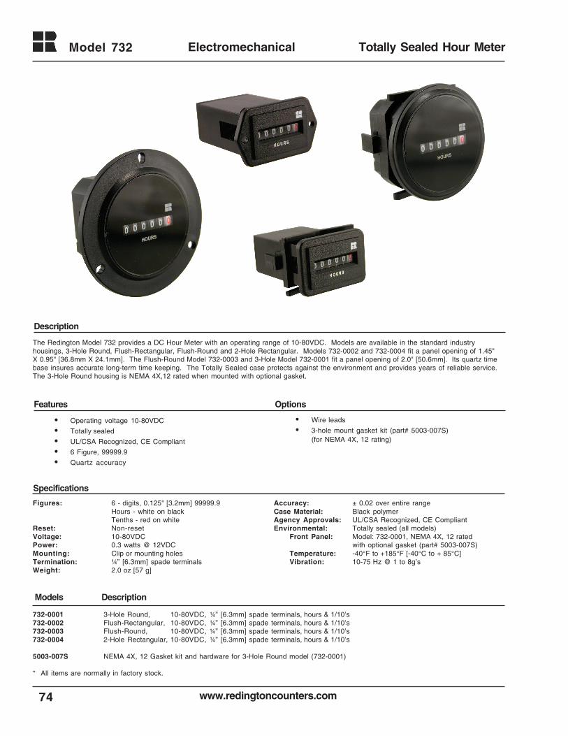
www.redingtoncounters.com
Model 732
74
Electromechanical Totally Sealed Hour Meter
Models Description
Specifications
Features Options
Description
The Redington Model 732 provides a DC Hour Meter with an operating range of 10-80VDC. Models are available in the standard industryhousings, 3-Hole Round, Flush-Rectangular, Flush-Round and 2-Hole Rectangular. Models 732-0002 and 732-0004 fit a panel opening of 1.45"X 0.95" [36.8mm X 24.1mm]. The Flush-Round Model 732-0003 and 3-Hole Model 732-0001 fit a panel opening of 2.0" [50.6mm]. Its quartz timebase insures accurate long-term time keeping. The Totally Sealed case protects against the environment and provides years of reliable service.The 3-Hole Round housing is NEMA 4X,12 rated when mounted with optional gasket.
• Operating voltage 10-80VDC
• Totally sealed
• UL/CSA Recognized, CE Compliant
• 6 Figure, 99999.9
• Quartz accuracy
• Wire leads
• 3-hole mount gasket kit (part# 5003-007S)(for NEMA 4X, 12 rating)
Figures: 6 - digits, 0.125" [3.2mm] 99999.9Hours - white on blackTenths - red on white
Reset: Non-resetVoltage: 10-80VDCPower: 0.3 watts @ 12VDCMounting: Clip or mounting holesTermination: ¼” [6.3mm] spade terminalsWeight: 2.0 oz [57 g]
732-0001 3-Hole Round, 10-80VDC, ¼” [6.3mm] spade terminals, hours & 1/10’s732-0002 Flush-Rectangular, 10-80VDC, ¼” [6.3mm] spade terminals, hours & 1/10’s732-0003 Flush-Round, 10-80VDC, ¼” [6.3mm] spade terminals, hours & 1/10’s732-0004 2-Hole Rectangular, 10-80VDC, ¼” [6.3mm] spade terminals, hours & 1/10’s
5003-007S NEMA 4X, 12 Gasket kit and hardware for 3-Hole Round model (732-0001)
* All items are normally in factory stock.
Accuracy: ± 0.02 over entire rangeCase Material: Black polymerAgency Approvals: UL/CSA Recognized, CE CompliantEnvironmental: Totally sealed (all models)
Front Panel: Model: 732-0001, NEMA 4X, 12 ratedwith optional gasket (part# 5003-007S)
Temperature: -40°F to +185°F [-40°C to + 85°C]Vibration: 10-75 Hz @ 1 to 8g’s
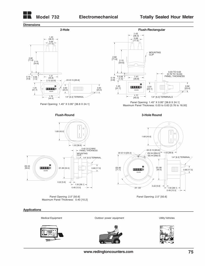
www.redingtoncounters.com 75
Model 732 Electromechanical Totally Sealed Hour Meter
Applications
Medical Equipment Outdoor power equipment Utility Vehicles
Dimensions
0.92[23.4]
1/4" [6.3] TERMINAL
2.15[54.6]
2.82[71.6]
1.75[44.4]
2.12 [53.8]
1.41[35.8]0.19
[4.8]
1.25[31.7]
0.06[1.5]
2X Ø.15 [Ø3.8]
0.92[23.4]
1.43[36.3]0.69[17.5]
0 0 0 0 0
0 0 0 0 00 0 0 0 0 0
0.49 [12.5]
1/4" [6.3] TERMINAL
3X Ø.13 [Ø3.3]3X Ø.15 [Ø3.8]
Ø2.44 [Ø62.0]Ø2.54 [Ø64.5]
Ø2.80 [71.1]
3X 120˚0.22 [5.6]
Ø1.99 [50.5]
1.50 [38.1]
1.69 [43.0]
1.53 [38.9]
0.69 [17.5]
0 0 0 0 00 0 0 0 0 0
0.49 [12.5]
1/4" [6.3] TERMINAL
0.40 [10.2] MAXPANEL THICKNESS
Ø2.33[59.2] Ø1.99 [50.5]
0.22 [5.6]1.50 [38.1]
1.53 [38.9]
1.69 [43.0]
0.69 [17.5]
MOUNTINGCLIP
0 0 0 0 00 0 0 0 0 0
0.03 TO 0.63[0.76 TO 16.00]
PANEL THICKNESS
0.92[23.4]
1/4" [6.3] TERMINALS
2.15[54.6]
2.82[71.6]
1.77[45.0]
1.41[35.8]0.19
[4.8]
1.25[31.7]
0.06[1.5]
0.91[23.1]
0.69[17.5]
1.43 [36.3]
MOUNTING CLIP
0 0 0 0 00 0 0 0 0 0
Panel Opening: 2.0" [50.6]Maximum Panel Thickness: 0.40 [10.2]
Panel Opening: 2.0" [50.6]
Panel Opening: 1.45" X 0.95" [36.8 X 24.1]Panel Opening: 1.45" X 0.95" [36.8 X 24.1]
Maximum Panel Thickness: 0.03 to 0.63 [0.76 to 16.00]
2-Hole
3-Hole RoundFlush-Round
Flush-Rectangular
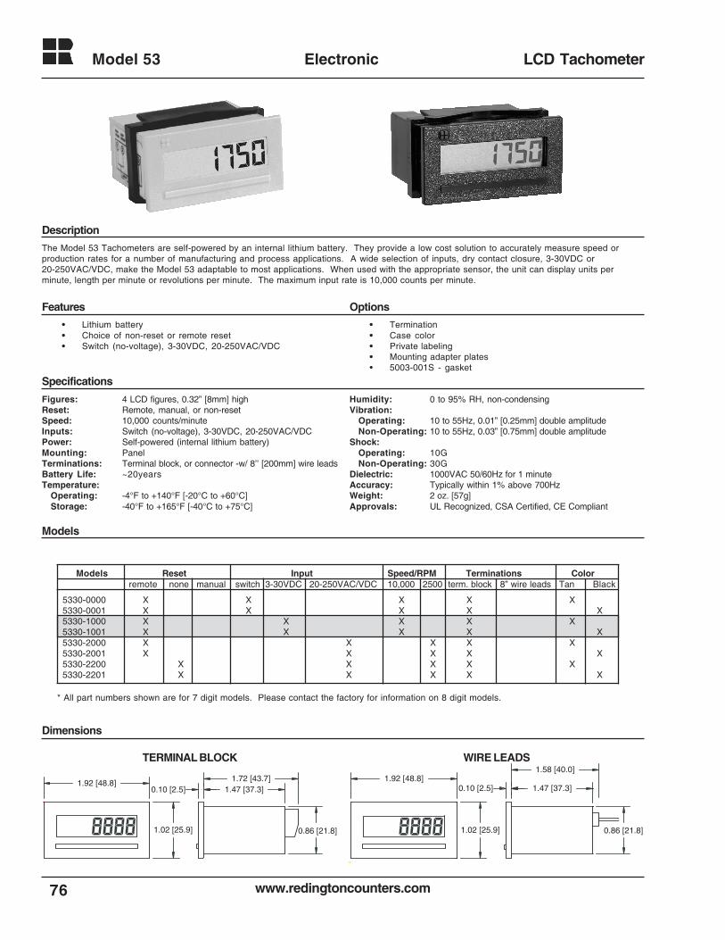
www.redingtoncounters.com
Model 53
76
Electronic LCD Tachometer
The Model 53 Tachometers are self-powered by an internal lithium battery. They provide a low cost solution to accurately measure speed orproduction rates for a number of manufacturing and process applications. A wide selection of inputs, dry contact closure, 3-30VDC or20-250VAC/VDC, make the Model 53 adaptable to most applications. When used with the appropriate sensor, the unit can display units perminute, length per minute or revolutions per minute. The maximum input rate is 10,000 counts per minute.
TERMINAL BLOCK WIRE LEADS
Figures: 4 LCD figures, 0.32” [8mm] highReset: Remote, manual, or non-resetSpeed: 10,000 counts/minuteInputs: Switch (no-voltage), 3-30VDC, 20-250VAC/VDCPower: Self-powered (internal lithium battery)Mounting: PanelTerminations: Terminal block, or connector -w/ 8’’ [200mm] wire leadsBattery Life: ~20yearsTemperature:
Operating: -4°F to +140°F [-20°C to +60°C]Storage: -40°F to +165°F [-40°C to +75°C]
Humidity: 0 to 95% RH, non-condensingVibration:
Operating: 10 to 55Hz, 0.01” [0.25mm] double amplitudeNon-Operating: 10 to 55Hz, 0.03” [0.75mm] double amplitude
Shock:Operating: 10GNon-Operating: 30G
Dielectric: 1000VAC 50/60Hz for 1 minuteAccuracy: Typically within 1% above 700HzWeight: 2 oz. [57g]Approvals: UL Recognized, CSA Certified, CE Compliant
• Lithium battery• Choice of non-reset or remote reset• Switch (no-voltage), 3-30VDC, 20-250VAC/VDC
• Termination• Case color• Private labeling• Mounting adapter plates• 5003-001S - gasket
Description
Features Options
Specifications
Models
Dimensions
0.86 [21.8]
0.10 [2.5]1.72 [43.7]
1.02 [25.9]
1.47 [37.3]1.92 [48.8]
0.86 [21.8]
0.10 [2.5]
1.58 [40.0]
1.02 [25.9]
1.47 [37.3]1.92 [48.8]
* All part numbers shown are for 7 digit models. Please contact the factory for information on 8 digit models.
5330-0000 X X X X X5330-0001 X X X X X5330-1000 X X X X X5330-1001 X X X X X5330-2000 X X X X X5330-2001 X X X X X5330-2200 X X X X X5330-2201 X X X X X
Models Reset Input Speed/RPM Terminations Colorremote none manual switch 3-30VDC 20-250VAC/VDC 10,000 2500 term. block 8” wire leads Tan Black
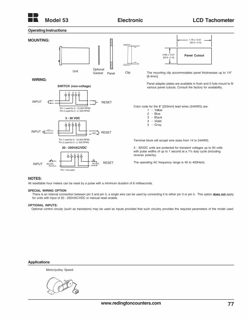
www.redingtoncounters.com 77
Model 53 Electronic LCD Tachometer
Motor/pulley Speed
Applications
MOUNTING:
UnitOptionalGasket Panel Clip
WIRING:
The mounting clip accommodates panel thicknesses up to 1/4”[6.4mm].
Panel adapter plates are available in flush and 2 hole mount to fitvarious panel cutouts. Consult the factory for availability.
Color code for the 8” [203mm] lead wires (24AWG) are:1 - Yellow2 - Blue3 - Black4 - Violet5 - Gray
NOTES:All resettable hour meters can be reset by a pulse with a minimum duration of 6 milliseconds.
SPECIAL WIRING OPTIONThere is an internal connection between pin 3 and pin 5, a single wire can be used by connecting it to either pin 3 or pin 5. This option does not applyfor units with input of 20 - 250VAC/VDC or manual reset enable.
OPTIONAL INPUTS:Optional control circuity (such as transistors) may be used as inputs provided that such circuitry provides the required parameters of the model used.
1.79 +/- 0.01 [45.5 +1/-0]
0.89 +/- 0.01 [22.6 +1/-0]
Panel Cutout
Pin 1 not used
RESETINPUT
20 - 250VAC/VDC
1 2 3 4 5
AC/DC AC/DC
RESETINPUT
Pin 1 used for 0 - 10,000 RPM)Pin 2 used for 0 - 2, 500 RPM)
3 - 30 VDC
1 2 3 4 5
+DC+DC
Terminal block will accept wire sizes from 14 to 24AWG.
3 - 30VDC units are protected for transient voltages up to 50 voltswith pulse widths of up to 1 second at a 1% duty cycle (includingreverse polarity).
The operating AC frequency range is 40 to 400Hertz.
SWITCH (non-voltage)
RESETINPUT
Pin 1 used for 0 - 10,000 RPM)Pin 2 used for 0 - 2, 500 RPM)
1 2 3 4 5
Operating Instructions
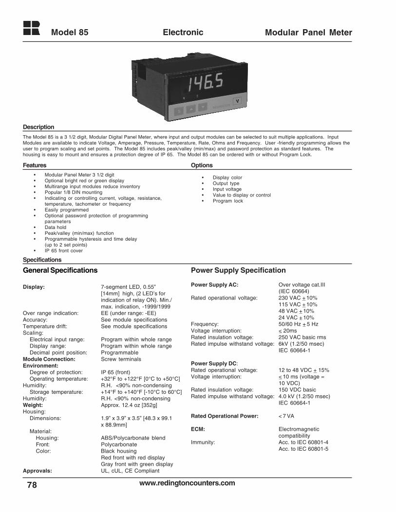
www.redingtoncounters.com
Model 85
78
Electronic Modular Panel Meter
Description
Features Options
Specifications
The Model 85 is a 3 1/2 digit, Modular Digital Panel Meter, where input and output modules can be selected to suit multiple applications. InputModules are available to indicate Voltage, Amperage, Pressure, Temperature, Rate, Ohms and Frequency. User -friendly programming allows theuser to program scaling and set points. The Model 85 includes peak/valley (min/max) and password protection as standard features. Thehousing is easy to mount and ensures a protection degree of IP 65. The Model 85 can be ordered with or without Program Lock.
• Modular Panel Meter 3 1/2 digit• Optional bright red or green display• Multirange input modules reduce inventory• Popular 1/8 DIN mounting• Indicating or controlling current, voltage, resistance,
temperature, tachometer or frequency• Easily programmed• Optional password protection of programming
parameters• Data hold• Peak/valley (min/max) function• Programmable hysteresis and time delay
(up to 2 set points)• IP 65 front cover
General Specifications
Display: 7-segment LED, 0.55”[14mm] high, (2 LED’s forindication of relay ON). Min./max. indication, -1999/1999
Over range indication: EE (under range: -EE)Accuracy: See module specificationsTemperature drift: See module specificationsScaling:
Electrical input range: Program within whole rangeDisplay range: Program within whole rangeDecimal point position: Programmable
Module Connection: Screw terminalsEnvironment:
Degree of protection: IP 65 (front)Operating temperature: +32°F to +122°F [0°C to +50°C]
Humidity: R.H. <90% non-condensingStorage temperature: +14°F to +140°F [-10°C to 60°C]
Humidity: R.H. <90% non-condensingWeight: Approx. 12.4 oz [352g]Housing:
Dimensions: 1.9” x 3.9” x 3.5” [48.3 x 99.1x 88.9mm]
Material:Housing: ABS/Polycarbonate blendFront: PolycarbonateColor: Black housing
Red front with red displayGray front with green display
Approvals: UL, cUL, CE Compliant
Power Supply Specification
Power Supply AC: Over voltage cat.III(IEC 60664)
Rated operational voltage: 230 VAC + 10%115 VAC + 10%48 VAC + 10%24 VAC + 10%
Frequency: 50/60 Hz + 5 HzVoltage interruption: < 20msRated insulation voltage: 250 VAC basic rmsRated impulse withstand voltage: 6kV (1.2/50 msec)
IEC 60664-1
Power Supply DC:Rated operational voltage: 12 to 48 VDC + 15%Voltage interruption: < 10 ms (voltage =
10 VDC)Rated insulation voltage: 150 VDC basicRated impulse withstand voltage: 4.0 kV (1.2/50 msec)
IEC 60664-1
Rated Operational Power: < 7 VA
ECM: Electromagneticcompatibility
Immunity: Acc. to IEC 60801-4Acc. to IEC 60801-5
• Display color• Output type• Input voltage• Value to display or control• Program lock
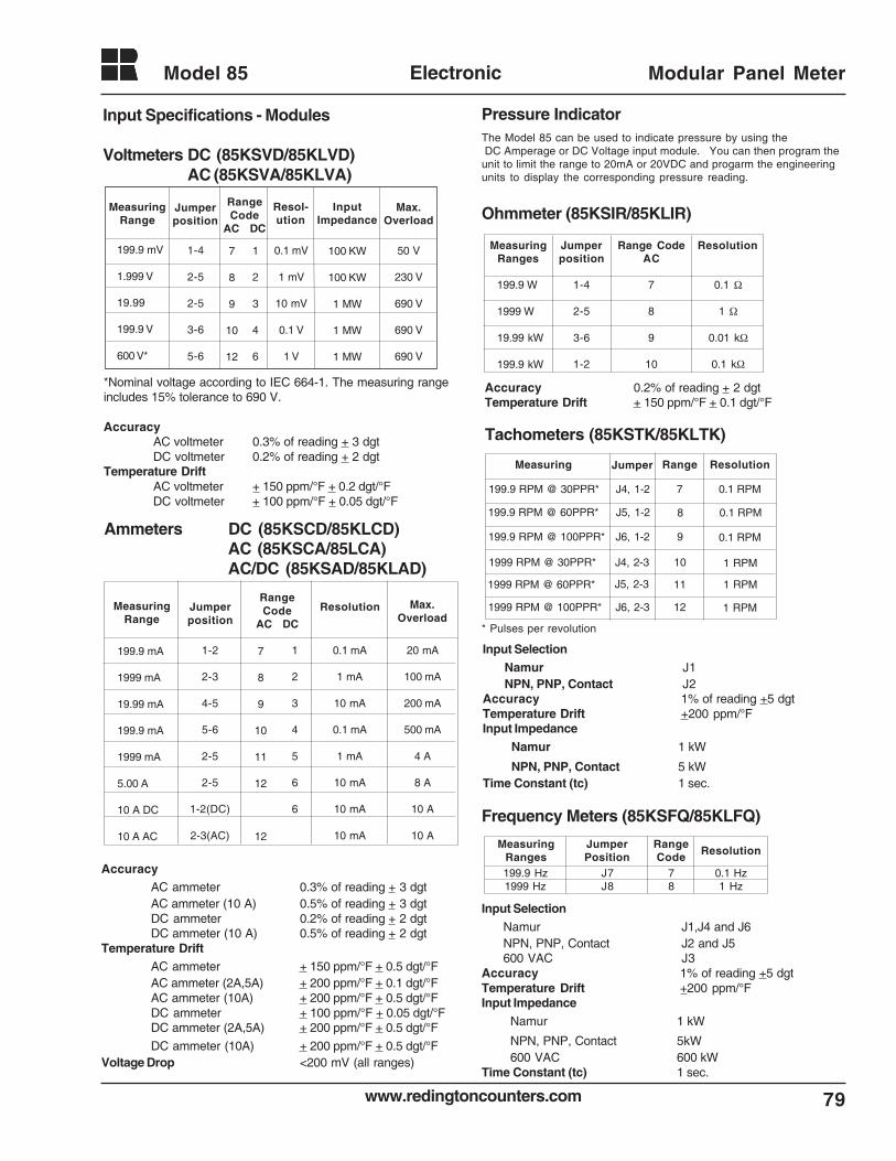
79www.redingtoncounters.com
Model 85 Electronic Modular Panel Meter
*Nominal voltage according to IEC 664-1. The measuring rangeincludes 15% tolerance to 690 V.
AccuracyAC voltmeter 0.3% of reading + 3 dgtDC voltmeter 0.2% of reading + 2 dgt
Temperature DriftAC voltmeter + 150 ppm/°F + 0.2 dgt/°FDC voltmeter + 100 ppm/°F + 0.05 dgt/°F
Ammeters DC (85KSCD/85KLCD)AC (85KSCA/85LCA)AC/DC (85KSAD/85KLAD)
AccuracyAC ammeter 0.3% of reading + 3 dgtAC ammeter (10 A) 0.5% of reading + 3 dgtDC ammeter 0.2% of reading + 2 dgtDC ammeter (10 A) 0.5% of reading + 2 dgt
Temperature DriftAC ammeter + 150 ppm/°F + 0.5 dgt/°FAC ammeter (2A,5A) + 200 ppm/°F + 0.1 dgt/°FAC ammeter (10A) + 200 ppm/°F + 0.5 dgt/°FDC ammeter + 100 ppm/°F + 0.05 dgt/°FDC ammeter (2A,5A) + 200 ppm/°F + 0.5 dgt/°F
DC ammeter (10A) + 200 ppm/°F + 0.5 dgt/°FVoltage Drop <200 mV (all ranges)
Input Specifications - Modules
Voltmeters DC (85KSVD/85KLVD)AC (85KSVA/85KLVA)
MeasuringRange
Jumperposition
RangeCode
AC DC
Resolution Max.Overload
199.9 mA
1999 mA
19.99 mA
199.9 mA
1999 mA
5.00 A
10 A DC
10 A AC
1-2
2-3
4-5
5-6
2-5
2-5
1-2(DC)
2-3(AC)
7
8
9
10
11
12
12
1
2
3
4
5
6
6
0.1 mA
1 mA
10 mA
0.1 mA
1 mA
10 mA
10 mA
10 mA
20 mA
100 mA
200 mA
500 mA
4 A
8 A
10 A
10 A
MeasuringRange
Jumperposition
RangeCode
AC DC
Resol-ution
InputImpedance
Max.Overload
199.9 mV
1.999 V
19.99
199.9 V
600 V*
1-4
2-5
2-5
3-6
5-6
7
8
9
10
12
1
2
3
4
6
0.1 mV
1 mV
10 mV
0.1 V
1 V
100 KW
100 KW
1 MW
1 MW
1 MW
50 V
230 V
690 V
690 V
690 V
Ohmmeter (85KSIR/85KLIR)
Accuracy 0.2% of reading + 2 dgtTemperature Drift + 150 ppm/°F + 0.1 dgt/°F
Tachometers (85KSTK/85KLTK)
* Pulses per revolution
Input SelectionNamur J1NPN, PNP, Contact J2
Accuracy 1% of reading +5 dgtTemperature Drift +200 ppm/°FInput Impedance
Namur 1 kW
NPN, PNP, Contact 5 kWTime Constant (tc) 1 sec.
Frequency Meters (85KSFQ/85KLFQ)
Input SelectionNamur J1,J4 and J6NPN, PNP, Contact J2 and J5600 VAC J3
Accuracy 1% of reading +5 dgtTemperature Drift +200 ppm/°FInput Impedance
Namur 1 kW
NPN, PNP, Contact 5kW600 VAC 600 kW
Time Constant (tc) 1 sec.
MeasuringRanges
Jumperposition
Range CodeAC
Resolution
199.9 W
1999 W
19.99 kW
199.9 kW
1-4
2-5
3-6
1-2
7
8
9
10
0.1 Ω
1 Ω
0.01 kΩ
0.1 kΩ
Measuring Jumper Range Resolution
199.9 RPM @ 30PPR*
199.9 RPM @ 60PPR*
199.9 RPM @ 100PPR*
1999 RPM @ 30PPR*
1999 RPM @ 60PPR*
1999 RPM @ 100PPR*
J4, 1-2
J5, 1-2
J6, 1-2
J4, 2-3
J5, 2-3
J6, 2-3
7
8
9
10
11
12
0.1 RPM
0.1 RPM
0.1 RPM
1 RPM
1 RPM
1 RPM
199.9 Hz1999 Hz
J7J8
78
0.1 Hz1 Hz
MeasuringRanges
JumperPosition
RangeCode Resolution
Pressure IndicatorThe Model 85 can be used to indicate pressure by using the DC Amperage or DC Voltage input module. You can then program theunit to limit the range to 20mA or 20VDC and progarm the engineeringunits to display the corresponding pressure reading.
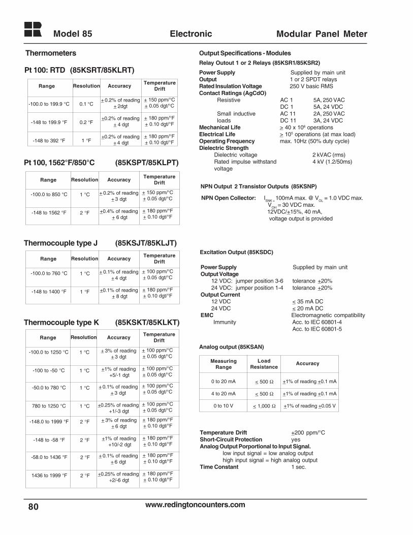
www.redingtoncounters.com
Model 85
80
Electronic Modular Panel Meter
Thermometers
Pt 100: RTD (85KSRT/85KLRT)
Pt 100, 1562°F/850°C (85KSPT/85KLPT)
Thermocouple type J (85KSJT/85KLJT)
Thermocouple type K (85KSKT/85KLKT)
Range Resolution AccuracyTemperature
Drift
-100.0 to 850 °C
-148 to 1562 °F
1 °C
2 °F
+ 0.2% of reading+ 3 dgt
+0.4% of reading + 6 dgt
+ 150 ppm/°C+ 0.05 dgt/°C
+ 180 ppm/°F+ 0.10 dgt/°F
Range Resolution AccuracyTemperature
Drift
-100.0 to 760 °C
-148 to 1400 °F
1 °C
1 °F
+ 0.1% of reading+ 4 dgt
+0.1% of reading + 8 dgt
+ 100 ppm/°C+ 0.05 dgt/°C
+ 180 ppm/°F+ 0.10 dgt/°F
Range Resolution AccuracyTemperature
Drift
-100.0 to 199.9 °C
-148 to 199.9 °F
-148 to 392 °F
0.1 °C
0.2 °F
1 °F
+ 0.2% of reading+ 2dgt
+0.2% of reading + 4 dgt
+0.2% of reading + 4 dgt
+ 150 ppm/°C+ 0.05 dgt/°C
+ 180 ppm/°F+ 0.10 dgt/°F
+ 180 ppm/°F+ 0.10 dgt/°F
Range Resolution AccuracyTemperature
Drift
-100.0 to 1250 °C
-100 to -50 °C
1 °C
1 °C
+ 3% of reading+ 3 dgt
+1% of reading +5/-1 dgt
+ 100 ppm/°C+ 0.05 dgt/°C
+ 100 ppm/°C+ 0.05 dgt/°C
-50.0 to 780 °C
780 to 1250 °C
1 °C
1 °C
+ 0.1% of reading+ 3 dgt
+0.25% of reading +1/-3 dgt
+ 100 ppm/°C+ 0.05 dgt/°C
+ 100 ppm/°C+ 0.05 dgt/°C
-148.0 to 1999 °F
-148 to -58 °F
2 °F
2 °F
+ 3% of reading+ 6 dgt
+1% of reading +10/-2 dgt
+ 180 ppm/°F+ 0.10 dgt/°F
+ 180 ppm/°F+ 0.10 dgt/°F
-58.0 to 1436 °F
1436 to 1999 °F
2 °F
2 °F
+ 0.1% of reading+ 6 dgt
+0.25% of reading +2/-6 dgt
+ 180 ppm/°F+ 0.10 dgt/°F
+ 180 ppm/°F+ 0.10 dgt/°F
Output Specifications - Modules
Relay Outout 1 or 2 Relays (85KSR1/85KSR2)
Power Supply Supplied by main unitOutput 1 or 2 SPDT relaysRated Insulation Voltage 250 V basic RMSContact Ratings (AgCdO)
Resistive AC 1 5A, 250 VACDC 1 5A, 24 VDC
Small inductive AC 11 2A, 250 VACloads DC 11 3A, 24 VDC
Mechanical Life > 40 x 106 operationsElectrical Life > 105 operations (at max load)Operating Frequency max. 10Hz (50% duty cycle)Dielectric Strength
Dielectric voltage 2 kVAC (rms)Rated impulse withstand 4 kV (1.2/50ms)voltage
Excitation Output (85KSDC)
Power Supply Supplied by main unitOutput Voltage
12 VDC: jumper position 3-6 tolerance +20%24 VDC: jumper position 1-4 tolerance +20%
Output Current12 VDC < 35 mA DC24 VDC < 20 mA DC
EMC Electromagnetic compatibilityImmunity Acc. to IEC 60801-4
Acc. to IEC 60801-5
Analog output (85KSAN)
Temperature Drift +200 ppm/°CShort-Circuit Protection yesAnalog Output Porportional to Input Signal.
low input signal = low analog outputhigh input signal = high analog output
Time Constant 1 sec.
NPN Output 2 Transistor Outputs (85KSNP)
NPN Open Collector: ISNK =
100mA max. @ VOL
= 1.0 VDC max. VOH = 30 VDC max. 12VDC/+15%, 40 mA, voltage output is provided
MeasuringRange
LoadResistance
Accuracy
0 to 20 mA
4 to 20 mA
0 to 10 V
< 500 Ω
< 500 Ω
< 1,000 Ω
+1% of reading +0.1 mA
+1% of reading +0.1 mA
+1% of reading +0.05 V
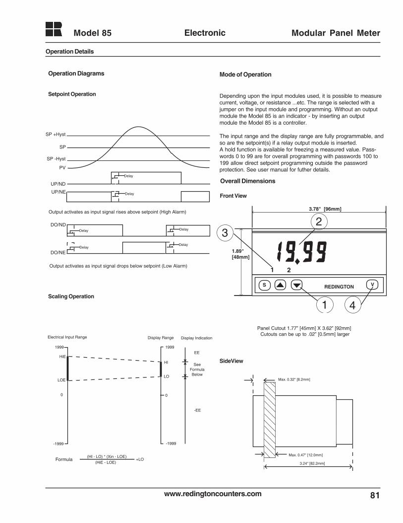
81www.redingtoncounters.com
Model 85 Electronic Modular Panel Meter
PV
SP -Hyst
SP
SP +Hyst
UP/ND
UP/NE
DO/ND
DO/NE
Delay
Delay
Delay
Delay
Delay
Delay
Output activates as input signal rises above setpoint (High Alarm)
Output activates as input signal drops below setpoint (Low Alarm)
Setpoint Operation
1999
-1999
HiE
LOE
0
1999
-1999
0
HI
LO
EE
-EE
SeeFormulaBelow
Electrical Input Range Display Range Display Indication
Formula (HI - LO) * (Xin - LOE)
(HiE - LOE)+LO
Scaling Operation
Operation Diagrams Mode of Operation
Depending upon the input modules used, it is possible to measurecurrent, voltage, or resistance ...etc. The range is selected with ajumper on the input module and programming. Without an outputmodule the Model 85 is an indicator - by inserting an outputmodule the Model 85 is a controller.
The input range and the display range are fully programmable, andso are the setpoint(s) if a relay output module is inserted.A hold function is available for freezing a measured value. Pass-words 0 to 99 are for overall programming with passwords 100 to199 allow direct setpoint programming outside the passwordprotection. See user manual for futher details.
Overall Dimensions
Front View
S V
1 2
3.78" [96mm]
1.89"[48mm]
REDINGTON
23
1 4
SideView
3.24" [82.2mm]
Max. 0.47" [12.0mm]
Max. 0.32" [8.2mm]
Panel Cutout 1.77” [45mm] X 3.62” [92mm] Cutouts can be up to .02” [0.5mm] larger
Operation Details
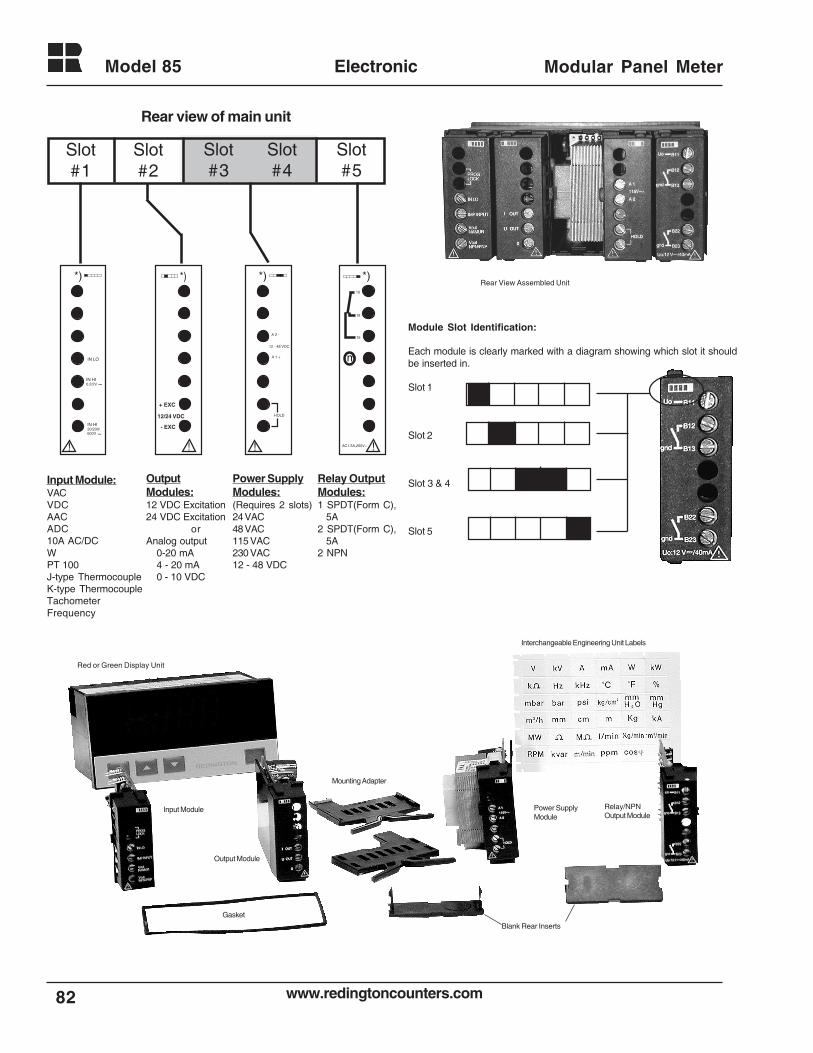
www.redingtoncounters.com
Model 85
82
Electronic Modular Panel Meter
Slot#3
Slot#4
Rear view of main unit
!
*)
IN LO
IN HI0.2/2V
IN HI20/200/600V ~
~
!
*)
+ EXC
- EXC
12/24 VDC
!
*)
A 2 -
12 - 48 VDC
A 1 +
HOLD
!
*)
AC1.5A,250V~
15
18
16
m
Input Module:VACVDCAACADC10A AC/DCWPT 100J-type ThermocoupleK-type ThermocoupleTachometerFrequency
OutputModules:12 VDC Excitation24 VDC Excitation
orAnalog output
0-20 mA4 - 20 mA0 - 10 VDC
Power SupplyModules:(Requires 2 slots)24 VAC48 VAC115 VAC230 VAC12 - 48 VDC
Relay OutputModules:1 SPDT(Form C),
5A2 SPDT(Form C),
5A2 NPN
Slot#1
Slot#2
Slot#5
Red or Green Display Unit
Interchangeable Engineering Unit Labels
Blank Rear Inserts
Gasket
Mounting Adapter
Input Module
Output Module
Power SupplyModule
Relay/NPNOutput Module
Rear View Assembled Unit
Module Slot Identification:
Each module is clearly marked with a diagram showing which slot it shouldbe inserted in.
Slot 1
Slot 2
Slot 3 & 4
Slot 5
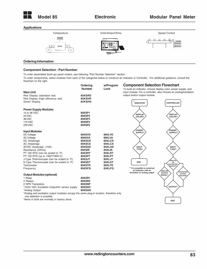
83www.redingtoncounters.com
Model 85 Electronic Modular Panel Meter
Ordering Information
Component Selection - Part NumberTo order assembled (built-up) panel meters, see following “Part Number Selection” section.To order components, select modules from each of the categories below to construct an Indicator or Controller. For additional guidance, consult theflowchart on the right.
Ordering w/Program Number Lock
Main UnitRed Display (standard red) 85KSRDRed Display (high efficiency red) 85KSHRGreen Display 85KSHG
Power Supply Modules12 to 48 VDC 85KSP124 VAC 85KSP248 VAC 85KSP3115 VAC 85KSP4230 VAC 85KSP5
Input ModulesDC Voltage 85KSVD 85KLVDAC Voltage 85KSVA 85KLVADC Amperage 85KSCD 85KLCDAC Amperage 85KSCA 85KLCAAC/DC Amperage (10A) 85KSAD 85KLADResistance (Ohms) 85KSIR 85KLIRPT 100 RTD (can be scaled to °F) 85KSRT 85KLRTPT 100 RTD (up to 1562°F/850°C) 85KSPT 85KLPTJ-Type Thermocouple (can be scaled to °F) 85KSJT 85KLJTK-Type Thermocouple (can be scaled to °F) 85KSKT 85KLKTTachometer 85KSTK 85KLTKFrequency 85KSFQ 85KLFQ
Output Modules (optional)1 Relay 85KSR12 Relays 85KSR22 NPN Transistors 85KSNP*12/24 VDC Excitation Output/for sensor supply 85KSDC*Analog Output 85KSAN*Analog and excitation output modules occupy the same plug-in location, therefore only
one selection is possible.*Items in bold are normally in factory stock.
INDICATOR
DISPLAYCOLOR?
POWERSUPPLY?
INPUTTYPE?
END
DISPLAYCOLOR?
POWERSUPPLY?
INPUTTYPE?
CONTROLLER**
ANALOGOR
EXCITATIONOUTPUT?
ANALOGOUTPUTSIGNAL?
EXCITATIONOUTPUT
VOLTAGE?
OUTPUT?
END
** It is possible to constructan indicator with an
excitation or analog output
Component Selection FlowchartTo build an indicator, choose display color, power supply, andinput module. For a controller, also choose an analog/excitationoutput and/or output module.
Applications
Temperature Volts/Amps/Ohms Speed Control
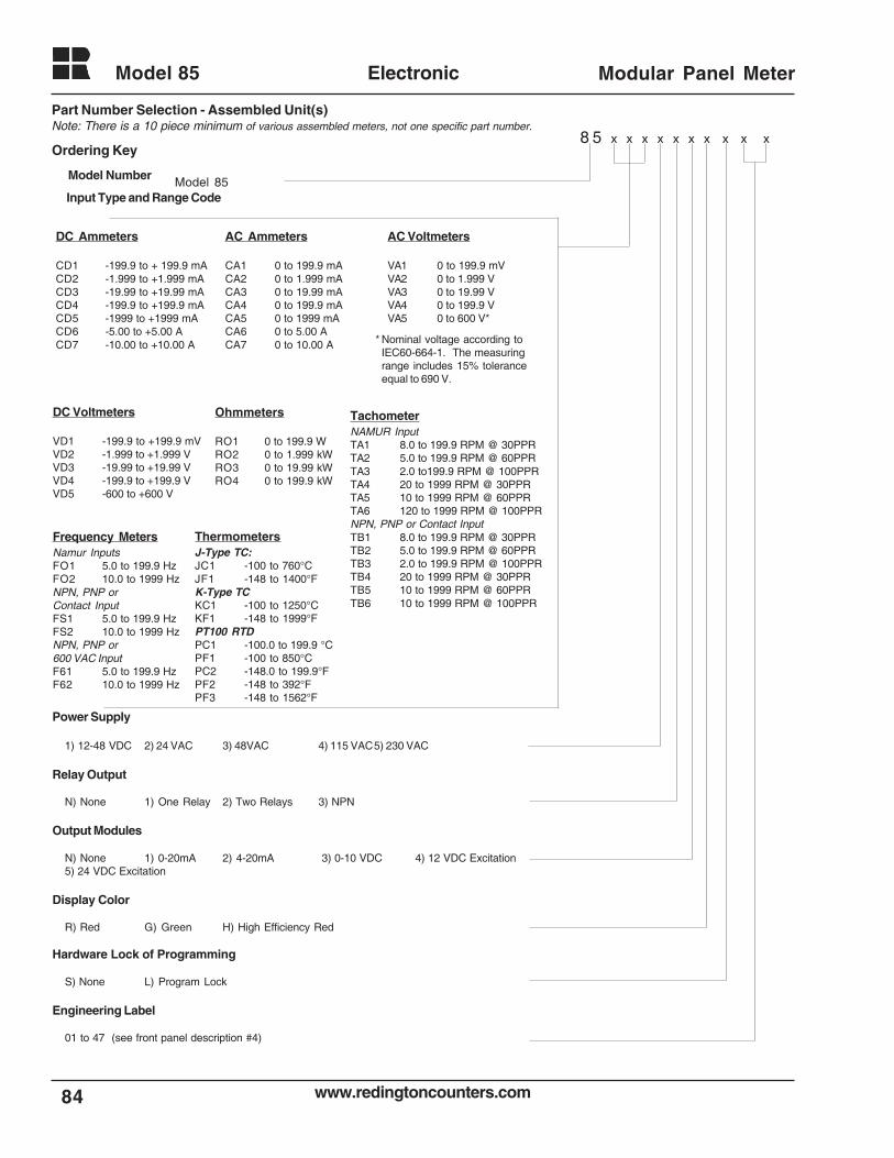
www.redingtoncounters.com
Model 85
84
Electronic Modular Panel Meter
Ordering Key
Model Number
Input Type and Range Code
DC Ammeters
CD1 -199.9 to + 199.9 mACD2 -1.999 to +1.999 mACD3 -19.99 to +19.99 mACD4 -199.9 to +199.9 mACD5 -1999 to +1999 mACD6 -5.00 to +5.00 ACD7 -10.00 to +10.00 A
AC Ammeters
CA1 0 to 199.9 mACA2 0 to 1.999 mACA3 0 to 19.99 mACA4 0 to 199.9 mACA5 0 to 1999 mACA6 0 to 5.00 ACA7 0 to 10.00 A
DC Voltmeters
VD1 -199.9 to +199.9 mVVD2 -1.999 to +1.999 VVD3 -19.99 to +19.99 VVD4 -199.9 to +199.9 VVD5 -600 to +600 V
AC Voltmeters
VA1 0 to 199.9 mVVA2 0 to 1.999 VVA3 0 to 19.99 VVA4 0 to 199.9 VVA5 0 to 600 V*
ThermometersJ-Type TC:JC1 -100 to 760°CJF1 -148 to 1400°FK-Type TCKC1 -100 to 1250°CKF1 -148 to 1999°FPT100 RTDPC1 -100.0 to 199.9 °CPF1 -100 to 850°CPC2 -148.0 to 199.9°FPF2 -148 to 392°FPF3 -148 to 1562°F
Ohmmeters
RO1 0 to 199.9 WRO2 0 to 1.999 kWRO3 0 to 19.99 kWRO4 0 to 199.9 kW
Frequency MetersNamur InputsFO1 5.0 to 199.9 HzFO2 10.0 to 1999 HzNPN, PNP orContact InputFS1 5.0 to 199.9 HzFS2 10.0 to 1999 HzNPN, PNP or600 VAC InputF61 5.0 to 199.9 HzF62 10.0 to 1999 Hz
TachometerNAMUR InputTA1 8.0 to 199.9 RPM @ 30PPRTA2 5.0 to 199.9 RPM @ 60PPRTA3 2.0 to199.9 RPM @ 100PPRTA4 20 to 1999 RPM @ 30PPRTA5 10 to 1999 RPM @ 60PPRTA6 120 to 1999 RPM @ 100PPRNPN, PNP or Contact InputTB1 8.0 to 199.9 RPM @ 30PPRTB2 5.0 to 199.9 RPM @ 60PPRTB3 2.0 to 199.9 RPM @ 100PPRTB4 20 to 1999 RPM @ 30PPRTB5 10 to 1999 RPM @ 60PPRTB6 10 to 1999 RPM @ 100PPR
* Nominal voltage according toIEC60-664-1. The measuringrange includes 15% toleranceequal to 690 V.
Part Number Selection - Assembled Unit(s)Note: There is a 10 piece minimum of various assembled meters, not one specific part number.
8 5 x x x x x x x x x x
Model 85
Power Supply
1) 12-48 VDC 2) 24 VAC 3) 48VAC 4) 115 VAC5) 230 VAC
Relay Output
N) None 1) One Relay 2) Two Relays 3) NPN
Output Modules
N) None 1) 0-20mA 2) 4-20mA 3) 0-10 VDC 4) 12 VDC Excitation5) 24 VDC Excitation
Display Color
R) Red G) Green H) High Efficiency Red
Hardware Lock of Programming
S) None L) Program Lock
Engineering Label
01 to 47 (see front panel description #4)
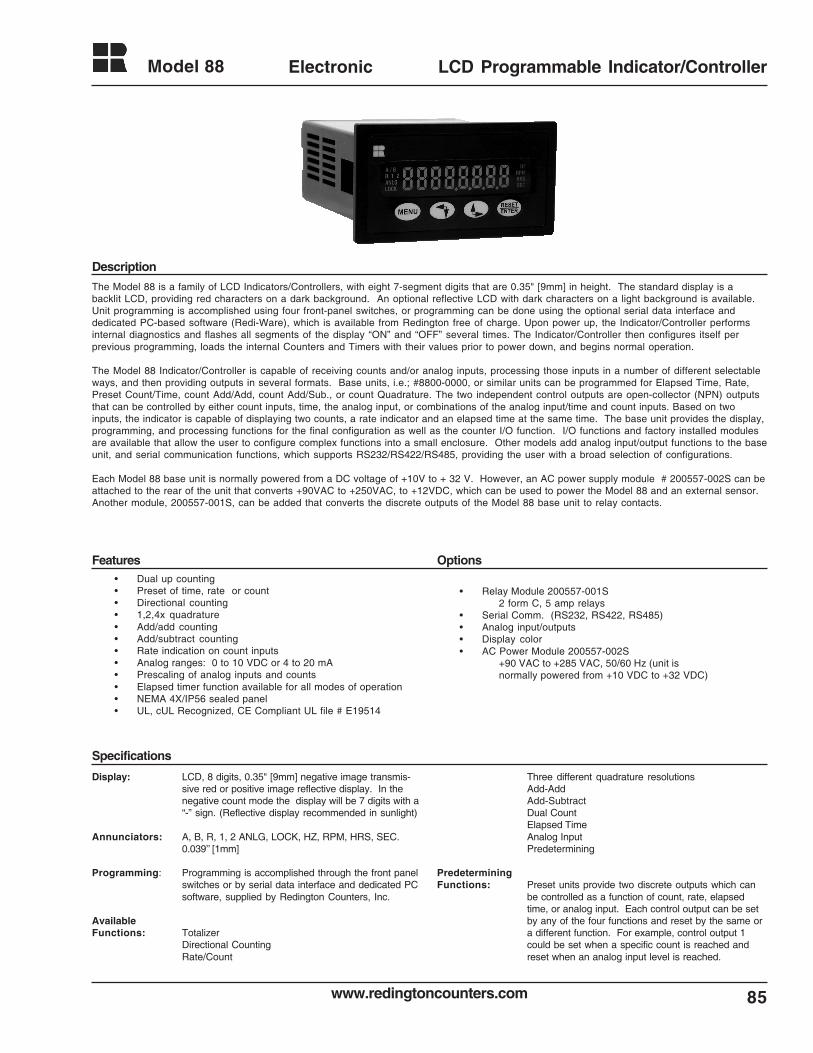
85www.redingtoncounters.com
Model 88 Electronic LCD Programmable Indicator/Controller
Description
Features Options
The Model 88 is a family of LCD Indicators/Controllers, with eight 7-segment digits that are 0.35" [9mm] in height. The standard display is abacklit LCD, providing red characters on a dark background. An optional reflective LCD with dark characters on a light background is available.Unit programming is accomplished using four front-panel switches, or programming can be done using the optional serial data interface anddedicated PC-based software (Redi-Ware), which is available from Redington free of charge. Upon power up, the Indicator/Controller performsinternal diagnostics and flashes all segments of the display “ON” and “OFF” several times. The Indicator/Controller then configures itself perprevious programming, loads the internal Counters and Timers with their values prior to power down, and begins normal operation.
The Model 88 Indicator/Controller is capable of receiving counts and/or analog inputs, processing those inputs in a number of different selectableways, and then providing outputs in several formats. Base units, i.e.; #8800-0000, or similar units can be programmed for Elapsed Time, Rate,Preset Count/Time, count Add/Add, count Add/Sub., or count Quadrature. The two independent control outputs are open-collector (NPN) outputsthat can be controlled by either count inputs, time, the analog input, or combinations of the analog input/time and count inputs. Based on twoinputs, the indicator is capable of displaying two counts, a rate indicator and an elapsed time at the same time. The base unit provides the display,programming, and processing functions for the final configuration as well as the counter I/O function. I/O functions and factory installed modulesare available that allow the user to configure complex functions into a small enclosure. Other models add analog input/output functions to the baseunit, and serial communication functions, which supports RS232/RS422/RS485, providing the user with a broad selection of configurations.
Each Model 88 base unit is normally powered from a DC voltage of +10V to + 32 V. However, an AC power supply module # 200557-002S can beattached to the rear of the unit that converts +90VAC to +250VAC, to +12VDC, which can be used to power the Model 88 and an external sensor.Another module, 200557-001S, can be added that converts the discrete outputs of the Model 88 base unit to relay contacts.
• Dual up counting• Preset of time, rate or count• Directional counting• 1,2,4x quadrature• Add/add counting• Add/subtract counting• Rate indication on count inputs• Analog ranges: 0 to 10 VDC or 4 to 20 mA• Prescaling of analog inputs and counts• Elapsed timer function available for all modes of operation• NEMA 4X/IP56 sealed panel• UL, cUL Recognized, CE Compliant UL file # E19514
• Relay Module 200557-001S2 form C, 5 amp relays
• Serial Comm. (RS232, RS422, RS485)• Analog input/outputs• Display color• AC Power Module 200557-002S
+90 VAC to +285 VAC, 50/60 Hz (unit isnormally powered from +10 VDC to +32 VDC)
Specifications
Display: LCD, 8 digits, 0.35" [9mm] negative image transmis-sive red or positive image reflective display. In thenegative count mode the display will be 7 digits with a“-” sign. (Reflective display recommended in sunlight)
Annunciators: A, B, R, 1, 2 ANLG, LOCK, HZ, RPM, HRS, SEC.0.039’’ [1mm]
Programming: Programming is accomplished through the front panelswitches or by serial data interface and dedicated PCsoftware, supplied by Redington Counters, Inc.
AvailableFunctions: Totalizer
Directional CountingRate/Count
Three different quadrature resolutionsAdd-AddAdd-SubtractDual CountElapsed TimeAnalog InputPredetermining
PredeterminingFunctions: Preset units provide two discrete outputs which can
be controlled as a function of count, rate, elapsedtime, or analog input. Each control output can be setby any of the four functions and reset by the same ora different function. For example, control output 1could be set when a specific count is reached andreset when an analog input level is reached.
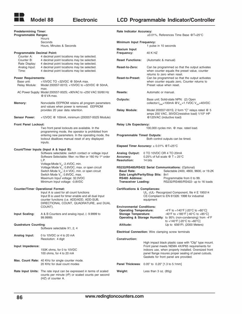
www.redingtoncounters.com
Model 88
86
Electronic LCD Programmable Indicator/Controller
Predetermining Timer:Programmable Ranges:
HoursSecondsHours, Minutes & Seconds
Programmable Decimal Point:Counter A: 4 decimal point locations may be selected.Counter B: 4 decimal point locations may be selected.Rate Display: 4 decimal point locations may be selected.Analog Input: 4 decimal point locations may be selected.Time: 4 decimal point locations may be selected.
Power Requirements:Base unit: +10VDC TO +32VDC @ 50mA max.Relay Module: Model 200557-001S; +10VDC to +32VDC @ 50mA,
max.AC Power Supply: Model 200557-002S; +90VAC to +250 VAC 50/60 Hz
@ 6 VA max.
Memory: Nonvolatile EEPROM retains all program parametersand values when power is removed. EEPROMprovides 20 year data retention.
Sensor Power: +12VDC @ 100mA, minimum (200557-002S Module)
Front Panel Lockout:Two front panel lockouts are available. In theprogramming mode, the operator is prohibited fromentering new parameters. In the operating mode, thelockout disallows manual reset of any displayedinputs.
Count/Timer Inputs (Input A & Input B):Software selectable: switch contact or voltage inputSoftware Selectable: filter: no filter or 160 Hz 1st orderL.P.Voltage Mode VIH: 2.4VDC, min.Voltage Mode VIL: 0.8VDC, max. or open circuitSwitch Mode VIH: 2.4 VDC, min. or open circuitSwitch Mode VIL: 0.8VDC, max.Maximum Input voltage: 32.0VDCMinimum Input voltage: -0.8VDC
Counter/Timer Operational Format:Input A is used for all count functionsInput B is used for timer enable and all dual Inputcounter functions (i.e. ADD/ADD, ADD-SUB,DIRECTIONAL COUNT, QUADRATURE, and DUALCOUNT).
Input Scaling: A & B Counters and analog input, (- 9.9999 to99.9999)
Quadrature Counting:Software selectable X1, 2, 4
Analog Input: 0 to 10VDC or 4 to 20 mAResolution: 4 digit
Input Impedence:150K ohms, for 0 to 10VDC100 ohms, for 4 to 20 mA
Max. Count Rate: 40 KHz for single counter mode.20 KHz for dual count modes
Rate Input Units: The rate input can be expressed in terms of scaledcounts per minute (rP) or scaled counts per second(HZ) of counter A.
Rate Indicator Accuracy:±0.01%, References Time Base @T=25°C
Minimum Input Frequency:1 pulse in 10 seconds
Maxium InputFrequency: 40 K HZ
Reset Functions: (Automatic & manual)
Reset-to-Zero: Can be programmed so that the output activateswhen counter equals the preset value, counterreturns to zero when reset.
Reset-to-Preset: Can be programmed so that the output activateswhen counter equals zero, Counter returns toPreset value when reset.
Resets: Automatic or manual.
Outputs: Base unit; Solid-state NPN: (2) Opencollector:ISNK=100mA @VOL=1.1VDC VOH=40VDC
Relay Module: Model 200557-001S; 2 form “C” relays rated @ 5amps 250 VAC, 30VDC(resistive load) 1/10th HP@120VAC (inductive load)
Relay Life Expectancy: 100,000 cycles min. @ max. rated load.
Programmable Timed Outputs: Both control outputs can be timed.
Elapsed Timer Accuracy: ± 0.01% @T=25°C
Analog Output: 0 TO 10VDC OR 4 TO 20mAAccuracy: 0.25% of full scale @ T = 25°CResolution: 14 bits
RS232/RS485/RS422 Serial Communications: (Optional)Baud Rate: Selectable 2400, 4800, 9600, or 19.2KData Length/Parity/Stop Bits: 8n1RS485 Address: Programmable from 0 to 99.Transceiver Loading: RS232/RS485/RS422- up to 16 loads
Certifications & Compliances:UL, cUL- Recognized Component, file # E 195514CE-Compliant to EN 61326: 1998 for industrialequipment
Environmental Conditions:Operating Temperature: -4°F to +140°F [-20°C to +60°C]Storage Temperature: -40°F to +185°F [-40°C to +85°C]Operating & Storage Humidity: to 95% (non-condensing) from -4°F
to +140°F [-20°C to +60°C]Altitude: Up to 6561Ft. (2000 Meters)
Electrical Connection: Wire clamping screw terminals
Construction:High impact black plastic case with “Clip” type mount.Front panel meets NEMA 4X/IP65 requirements forindoors use, when properly installed. Oversized frontpanel flange insures proper sealing of panel cutouts.Gaskets for front panel are provided.
Panel Thickness: 0.05" to 0.20" [1.3 to 5.1mm]
Weight: Less than 3 oz. (85g)
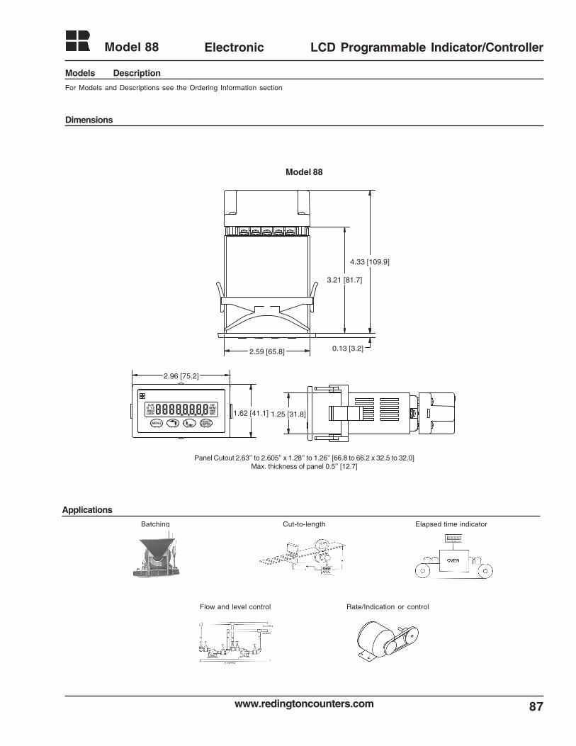
87www.redingtoncounters.com
Model 88 Electronic LCD Programmable Indicator/Controller
Models Description
Dimensions
Applications
For Models and Descriptions see the Ordering Information section
1.62 [41.1] 1.25 [31.8]
2.96 [75.2]
2.59 [65.8] 0.13 [3.2]
3.21 [81.7]
4.33 [109.9]
Model 88
Panel Cutout 2.63’’ to 2.605’’ x 1.28’’ to 1.26’’ [66.8 to 66.2 x 32.5 to 32.0]Max. thickness of panel 0.5’’ [12.7]
Batching Cut-to-length Elapsed time indicator
Flow and level control Rate/Indication or control
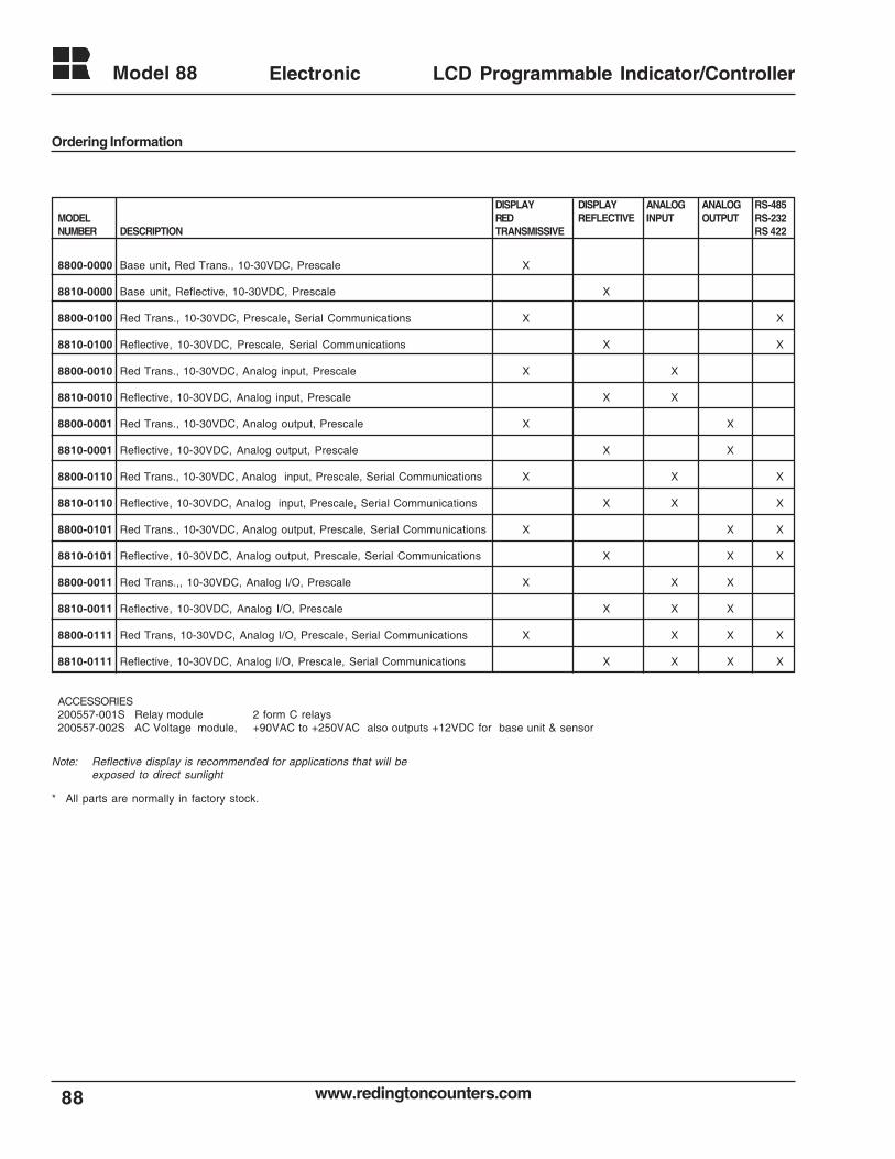
www.redingtoncounters.com
Model 88
88
Electronic LCD Programmable Indicator/Controller
DISPLAY DISPLAY ANALOG ANALOG RS-485MODEL RED REFLECTIVE INPUT OUTPUT RS-232NUMBER DESCRIPTION TRANSMISSIVE RS 422
8800-0000 Base unit, Red Trans., 10-30VDC, Prescale X
8810-0000 Base unit, Reflective, 10-30VDC, Prescale X
8800-0100 Red Trans., 10-30VDC, Prescale, Serial Communications X X
8810-0100 Reflective, 10-30VDC, Prescale, Serial Communications X X
8800-0010 Red Trans., 10-30VDC, Analog input, Prescale X X
8810-0010 Reflective, 10-30VDC, Analog input, Prescale X X
8800-0001 Red Trans., 10-30VDC, Analog output, Prescale X X
8810-0001 Reflective, 10-30VDC, Analog output, Prescale X X
8800-0110 Red Trans., 10-30VDC, Analog input, Prescale, Serial Communications X X X
8810-0110 Reflective, 10-30VDC, Analog input, Prescale, Serial Communications X X X
8800-0101 Red Trans., 10-30VDC, Analog output, Prescale, Serial Communications X X X
8810-0101 Reflective, 10-30VDC, Analog output, Prescale, Serial Communications X X X
8800-0011 Red Trans.,, 10-30VDC, Analog I/O, Prescale X X X
8810-0011 Reflective, 10-30VDC, Analog I/O, Prescale X X X
8800-0111 Red Trans, 10-30VDC, Analog I/O, Prescale, Serial Communications X X X X
8810-0111 Reflective, 10-30VDC, Analog I/O, Prescale, Serial Communications X X X X
ACCESSORIES200557-001S Relay module 2 form C relays200557-002S AC Voltage module, +90VAC to +250VAC also outputs +12VDC for base unit & sensor
Ordering Information
Note: Reflective display is recommended for applications that will beexposed to direct sunlight
* All parts are normally in factory stock.
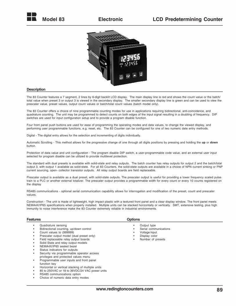
89www.redingtoncounters.com
Model 83 Electronic LCD Predetermining Counter
The 83 Counter features a 7 segment, 2 lines by 6-digit backlit LCD display. The main display line is red and shows the count value or the batch/total value when preset 3 or output 3 is viewed in the secondary display. The smaller secondary display line is green and can be used to view theprescaler value, preset values, output count values or batch/total count values (batch model only).
The 83 Counter offers a choice of nine programmable counting modes for use in applications requiring bidirectional, anti-coincidence, andquadrature counting. The unit may be programmed to detect counts on both edges of the input signal resulting in a doubling of frequency. DIPswitches are used for input configuration setup and to provide a program disable function.
Four front panel push buttons are used for ease of programming the operating modes and data values, to change the viewed display, andperforming user programmable functions, e.g. reset, etc. The 83 Counter can be configured for one of two numeric date entry methods.
Digital - The digital entry allows for the selection and incrementing of digits individually.
Automatic Scrolling - This method allows for the progressive change of one through all digits positions by pressing and holding the up or downbutton.
Protection of data value and unit configuration - The program disable DIP switch, a user-programmable code value, and an external user inputselected for program disable can be utilized to provide multilevel protection.
The standard with dual presets is available with solid-state and relay outputs. The batch counter has relay outputs for output 2 and the batch/totaloutput 3, with output 1 available as solid-state. For all 83 Counters, the solid-state outputs are available in a choice of NPN current sinking or PNPcurrent sourcing, open- collector transistor outputs. All relay output boards are field replaceable.
Prescaler output is available as a dual preset, with solid-state outputs. The prescaler output is useful for providing a lower frequency scaled pulsetrain to a PLC or another external totalizer. The prescaler output provides a programmable width for every count or every 10 counts registered onthe display
RS485 communications - optional serial communication capability allows for interrogation and modification of the preset, count and prescalervalues.
Construction - The unit is made of lightweight, high impact plastic with a textured front panel and a clear display window. The front panel meetsNEMA4X/IP65 specifications when properly installed. Multiple units can be stacked horizontally or vertically. SMT, extensive testing, plus highimmunity to noise interference make the 83 Counter extremely reliable in industrial environments.
• Quadrature sensing• Bidirectional counting, up/down control• Count values to (999999)• Prescaler output model (dual preset only)• Field replaceable relay output boards• Solid State and relay output models• NEMA4X/IP65 sealed bezel• Status indicators for outputs• Security via programmable operator access
privileges and protected values menu• Programmable user inputs and front panel
function key• Horizontal or vertical stacking of multiple units• 85 to 250VAC or 18 to 36VDC/24 VAC power units• RS485 communications option• Choice of numeric data entry modes
Description
Features Options
• Output type• Serial communications• Voltage input• Display color• Number of presets
www.redingtoncounters.com
Model 83
90
Electronic LCD Predetermining Counter
Display: 2 line by 6 digits LCD display, negative imagetransmissive with RED (top line) and GREEN(bottom line) backlighting. Positive image reflectivedisplay units are non-stock available.
Main: 0.3" (7.6mm) high digits Secondary: 0.2" (5mm) high digitsAnnunciators:
Value: PRS, 1,2 and 3Output: 01, 02 and 03
POWER REQUIREMENTS:AC Versions
AC Power: 85 to 250 VAC, 50/60Hz, 9VA max.DC Power: 11 to 14 VDC @ 159 mA max.
(Non PNP output models)Note: Models with PNP current sourcing outputs must be powered from
AC
DC VersionsDC Power: 18 to 36 VDC: 5.5 W max.
AC Power: 24 VAC +/- 10%: 50/60 Hz: 7VA max.Note: The 10% tolerance range on AC input voltage must be strictly
adhered to DO NOT EXCEED 26.4 VAC
PEAK (START-UP CURRENT) AC or DC Power: 500mA peak start-up current for 10 msec.
max.
DC OUT/ VSCR IN-terminal 10For units that do not have PNP current sourcing outputs, this terminalprovides a DC output for sensor power + 12 VDC (+/- 15%). Themaximum sensor current is 100mA.
For units with PNP current sourcing outputs this terminal serves a dualpurpose depending on the application PNP output voltage level andcurrent requirements.
1. The terminal may be used as a +12 VDC output for sensorpower. In this case, the PNP output voltage level will be+12 VDC (+/-15%). A maximum of 100 mA is available forthe combination of sensor and PNP output sourcingcurrent.
2. If a higher PNP output voltage level or additional outputsourcing current is needed, an external DC supply may beconnected between the “DC OUT ( V SRC IN)” and“COMM.” terminals. This supply will determine the PNPoutput voltage level, and must be in the same range of +13to +30 VDC.An external DC supply can also provide the additionaloutput sourcing current required in applications wheretwo or more PNP outputs are “ON” simultaneously.However, the maximum current range of 100mA perindividual output must not be exceeded, regardless ofexternal supply capacity.
3. Memory: Nonvolatile FRAM retains all program parameters andcount values.
4. SENSOR POWER: + 12 VDC (+/- 15%) @ 100mA max.
5. COUNT INPUTS A & B: Accepts count pulses from a variety ofsources, DIP switch selectable.
Current Sourcing: (active high): Vinmax. = 3.9K ohm pull-downto 30 VDC.
Current Sinking: (active low): 7.8 K ohm pull-up to 12 VDC :Isnk = 1.8mA max.
Debounce : 50 HzLo Bias: VIL = 1.5 VDC max., VIH = 3.75 VDC min.Hi Bias: VIL = 5.5 VDC max., VIH = 7.5 VDC min.
6. MAX. COUNT RATE: Model dependent. All listed values are in Khz.Note: Max. count rates for X2 & X4 modes are given for 50% duty
cycle signals and quad signals with 90° phase shift.
Prescaler C1-Usr C2-usr *Ad-sub QUAD Value C1-Ud C2-Ud Ad-Ad X1 X2 X4
0.00001-0.99999 8.3 4.1 8.6 4.5 4.1 2.11.00000 11.5 5.7 11.5 6.0 5.8 3.01.00001-2 6.5 3.2 6.6 4.0 3.2 1.62.00001-3 5.0 2.4 5.2 3.4 2.5 1.33.00001-4 4.1 2.0 4.4 2.8 2.0 1.04.00001-5 3.4 1.7 3.8 2.5 1.7 0.85.00001-6 2.9 1.4 3.2 2.2 1.4 0.76.00001-7 2.7 1.3 2.8 2.0 1.3 0.67.00001-8 2.2 1.1 2.4 1.8 1.2 0.68.00001-9 2.2 0.9 2.3 1.6 1.1 0.59.00001-9.99999 1.9 0.9 2.0 1.5 0.9 0.4
Dual Preset Model 8302
Prescaler C1-Usr C2-usr *Ad-sub QUAD Value C1-Ud C2-Ud Ad-Ad X1 X2 X4
0.00001-0.99999 8.3 4.1 8.4 3.7 3.6 2.21.00000 11.4 5.5 11.8 4.3 4.2 3.01.00001-2 6.5 3.2 6.6 3.2 3.0 1.62.00001-3 5.0 2.5 5.4 2.8 2.5 1.33.00001-4 4.1 2.0 4.2 2.4 2.0 1.04.00001-5 3.4 1.7 3.8 2.1 1.7 0.85.00001-6 2.9 1.4 3.2 1.9 1.5 0.76.00001-7 2.7 1.3 2.8 1.7 1.3 0.67.00001-8 2.4 1.1 2.6 1.6 1.2 0.68.00001-9 2.2 1.1 2.4 1.5 1.1 0.59.00001-9.99999 1.9 0.9 2.2 1.4 1.0 0.4
Batch Model 8303With Counter 2 configured as a Batch Counter (C2 A5n = bAtch)
Prescaler C1-Usr C2-usr *Ad-sub QUAD Value C1-Ud C2-Ud Ad-Ad X1 X2 X4
0.00001-0.99999 6.2 N/A N/A N/A N/A N/A1.00000 8.0 N/A N/A N/A N/A N/A
Prescaler Output Model 8304
* Inputs A & B rates summed.
Prescaler C1-Usr C2-usr *Ad-sub QUAD Value C1-Ud C2-Ud Ad-Ad X1 X2 X4
0.00001-0.99999 6.5 3.3 6.6 3.5 3.3 1.61.00000 8.5 3.6 8.6 4.0 4.0 2.1
Batch Model 8303With Counter 2 configured as a Total Counter (C2 A5n = totAL)
Single Preset Model 8301 Prescaler C1-Usr C2-usr *Ad-sub QUAD
Value C1-Ud C2-Ud Ad-Ad X1 X2 X40.00001-0.99999 8.4 4.1 9.4 5.4 4.5 2.11.00000 12.0 5.9 12.4 6.5 6.0 3.01.00001-2 6.6 3.2 6.8 4.3 3.3 1.62.00001-3 5.3 2.6 5.6 3.7 2.6 1.33.00001-4 4.3 2.1 4.6 3 2.2 1.14.00001-5 3.6 1.8 3.8 2.7 1.8 0.95.00001-6 3.1 1.5 3.4 2.4 1.6 0.86.00001-7 2.8 1.4 3.2 2.1 1.4 0.77.00001-8 2.6 1.3 2.8 1.9 1.3 0.68.00001-9 2.3 1.1 2.4 1.8 1.1 0.59.00001-9.99999 2.1 1.0 2.3 1.7 1.1 0.5
91www.redingtoncounters.com
Model 83 Electronic LCD Predetermining Counter
7. USER INPUTS: Configurable as current sinking (active low), orcurrent sourcing (active high) inputs via a single plugjumper.
Current Sinking: (active low) : VIL= 1.5 VDC max. 22 Kohm pull-ups to 5 VDC
Current Sourcing: (active high): VIH =3.5 min. VIN max. =30 VDC; 22K ohm pull-down.
Response Time: 10 msec. max.
Inhibit Response Time: 250 microsec max.
8. OUTPUTS: (Output type and quantity model dependent) Solid-State:
NPN Open Collector: ISNK= 100mA max. @ VOL = 1.1 VDCmax. ;VOH= 30 VDC max.
PNP Open Collector: ISRC = 100mA max. ( See note) ; VOH =12 VDC +/-15% ( using internal supply);VOH = 13 to 30 VDC ( using externalsupply).
Note: The internal supply of the 83 counter can provide a totalof 100 mA for the combination of sensor current and PNPoutput sourcing current. The supply voltage is +12 VDC (+/-15%), which will be the PNP output voltage level when using onlythe internal supply.If additional PNP output sourcing current or a higher outputvoltage level is desired, an external DC supply may beconnected between the “DC Out/In” and “Comm” terminals.This supply will determine the PNP output voltage level, andmust be in range of +13 to 30 VDC.An external supply can provide the additional output sourcingcurrent required in applications where two or more outputs are“ON” simultaneously. However, the maximum rating of 100mAper individual output must not be exceeded, regardless ofexternal supply capacity.
Relay: Form A contact, rating = 5 A @ 250 VAC, 30 VDC (resistiveload) , 1/10 HP @ 120 VAC (inductive load).
Relay Life Expectancy: 100,000 cycles min. at max. load rating.Programmable Timed Output: User selectable output time
resolutions.0.01 Second Resolution: 0.01 to 99.99 sec., +/-0.01%
+20 msec max. (Prescalers lessthan 2)
0.1 Second Resolution: 0.1 to 999.9 sec. +/- 0.01 + 100msec max. (Prescalers lessthan 2)
9. RS485 SERIAL COMMUNICATIONS (Optional): Up to 32 units canbe connected.
Baud Rate: Programmable from 1200 to 9600 baud.Address: Programmable from 0 to 99.Data Format:10 Bit Frame, 1 start bit , 7 or 8 data bits, 1 or no
Parity bit, and 1 stop bit.Parity: Programmable for Odd (7 data bits), Even ( 7 data
bits) or None ( 8 data bits).
10. CERTIFICATIONS AND COMPLIANCES:UL Recognized Component, File # E195514Recognized to U.S. and Canadian requirements under the ComponentRecognition Program of Underwriters Laboratories, Inc.
CE Compliant:ELECTROMAGNETIC COMPATIBILITY
Immunity to EN 50082-2electrostatic discharge EN 61000-4-2electromagnetic RF fields EN 61000-4-3fast transients EN 61000-4-4RF conducted interference EN 61000-4-6simulation of cordless phone EN V502204
Emissions to EN 50081-2RF interference EN 55011 enclosure class A
11. ENVIRONMENTAL CONDITIONS:Operating Temperature: +32°F to +122°F [0°C TO +50°C]Storage Temperature: -40°F to +158°F [-40°C to +70°C]Operating and Storage Humidity: 85% max. relative humidity (
non-condensing) from +32°F to +122°F [0°C to +50°C]
Altitude : Up to 6500 Feet [1981 Meters]12. ELECTRICAL CONNECTIONS: Wire clamping screw terminals.
13. CONSTRUCTION: Black plastic case with collar style panel latch.The panel latch can be installed for horizontal or vertical stacking.Black plastic textured bezel can be removed from the case withoutremoving the case from the panel or disconnecting the wiring. Frontpanel meets NEMA4X/IP65 requirements for indoor use, whenproperly installed. Installation Category II, Pollution Degree 2.
14. WEIGHT: 6.0 oz [170g]
SINGLE PRESET MODELSThe 8301 has a solid-state output that operates in parallel with a relayoutput. The solid-state output is available as an NPN or PNP opencollector transistor.
DUAL PRESET MODELSThe 8302 has two outputs that are activated from presets 1 and 2.These outputs can be relay or solid-state outputs. The solid-stateoutputs are available as NPN or PNP open-collector transistors. Unitswith solid-state outputs can be ordered with an optional prescaleroutput.
3 PRESET BATCH MODELSThe 8303 has a secondary counter that can be used for batchcounting, or to keep a total count. This second counter can beprogrammed to operate in one of eight operating modes. Output 1 and2 are assigned to the primary process counter (C1). Output 3 isassigned to the secondary Batch/Total counter (C2). The three presetbatch unit can be ordered with solid-state or relay outputs. Units withsolid-state outputs have a User Input 2 terminal available. The relaymodel has a relay output for Output 2 and Output 3 (Batch/Total).Output 1 is available only as solid-state.
PRESCALER OUTPUT MODELSThe 8304 is a dual preset counter with solid-state outputs. Thesemodels have an additional output configured as a prescaler output.Each time the least significant digit of the display increments, thePrescaler output provides a pulse. The width of this pulse is variable inthat the output will turn off after a programmed number of count inputpulses has occurred (1-9). The Prescaler output can also beprogrammed to activate when the 10’s digit of the display increments,rather than the least significant digit.
Note: Prescaler Output Models are limited to two programmable countmodes and prescaler values of 1.00000 or less. See CountInput Modes for available modes.
FRONT PANEL KEYPAD
- Performs user Programmed Function.
- Cycles through secondary displays.- Enters Programming Mode or Protected Value Menu when
pushed and held for 2 seconds.- Scrolls through programming displays.- Enters Data Values.
- Selects next available mode in programming mode.- Increments digit in digit Entry mode.- Increments value in Auto Scrolling entry mode.
- Selects Digit to right when in Digit Entry mode.- Decrements value in Auto Scrolling entry mode.
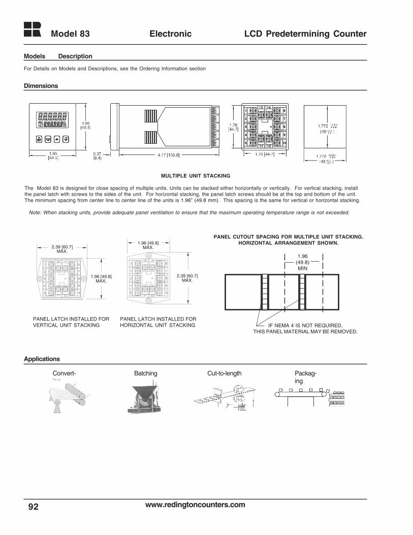
www.redingtoncounters.com
Model 83
92
Electronic LCD Predetermining Counter
Dimensions
For Details on Models and Descriptions, see the Ordering Information section
MULTIPLE UNIT STACKING
The Model 83 is designed for close spacing of multiple units. Units can be stacked either horizontally or vertically. For vertical stacking, installthe panel latch with screws to the sides of the unit. For horizontal stacking, the panel latch screws should be at the top and bottom of the unit.The minimum spacing from center line to center line of the units is 1.96” (49.8 mm). This spacing is the same for vertical or horizontal stacking.
Note: When stacking units, provide adequate panel ventilation to ensure that the maximum operating temperature range is not exceeded.
PANEL CUTOUT SPACING FOR MULTIPLE UNIT STACKING.HORIZONTAL ARRANGEMENT SHOWN.1.96 [49.8]
MAX.
2.39 [60.7]MAX.
2.39 [60.7]MAX.
1.96 [49.8]MAX.
PANEL LATCH INSTALLED FORVERTICAL UNIT STACKING
PANEL LATCH INSTALLED FORHORIZONTAL UNIT STACKING
Applications
Cut-to-lengthBatchingConvert-ing
Packag-ing
Models Description
IF NEMA 4 IS NOT REQUIRED,THIS PANEL MATERIAL MAY BE REMOVED.
1212121212121212
1212121212121212
1.96(49.8)MIN
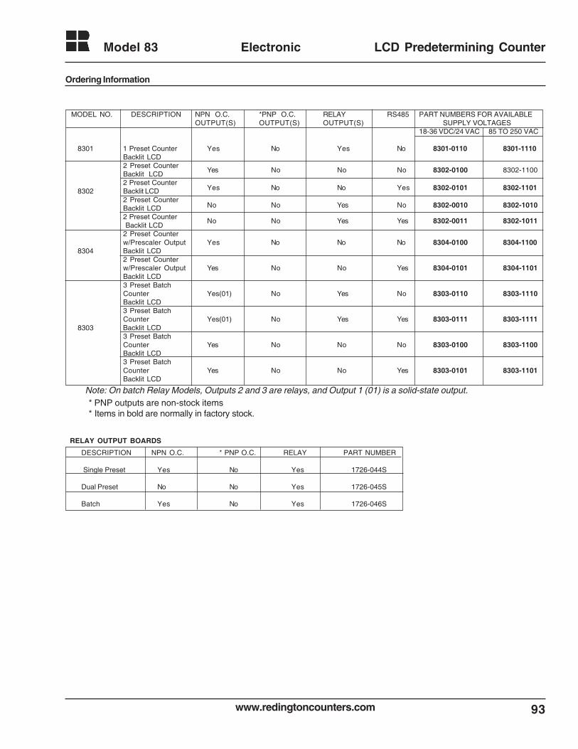
93www.redingtoncounters.com
Model 83 Electronic LCD Predetermining Counter
Ordering Information
RELAY OUTPUT BOARDS
DESCRIPTION NPN O.C. * PNP O.C. RELAY PART NUMBER
Single Preset Yes No Yes 1726-044S
Dual Preset No No Yes 1726-045S
Batch Yes No Yes 1726-046S
* PNP outputs are non-stock items* Items in bold are normally in factory stock.
Note: On batch Relay Models, Outputs 2 and 3 are relays, and Output 1 (01) is a solid-state output.
MODEL NO. DESCRIPTION NPN O.C. *PNP O.C. RELAY RS485 PART NUMBERS FOR AVAILABLEOUTPUT(S) OUTPUT(S) OUTPUT(S) SUPPLY VOLTAGES
18-36 VDC/24 VAC 85 TO 250 VAC
8301 1 Preset Counter Yes No Yes No 8301-0110 8301-1110Backlit LCD2 Preset Counter
Yes No No No 8302-0100 8302-1100Backlit LCD2 Preset Counter
Yes No No Yes 8302-0101 8302-11018302 Backlit LCD2 Preset CounterBacklit LCD No No Yes No 8302-0010 8302-1010
2 Preset Counter Backlit LCD
No No Yes Yes 8302-0011 8302-1011
2 Preset Counterw/Prescaler Output Yes No No No 8304-0100 8304-1100
8304 Backlit LCD2 Preset Counterw/Prescaler Output Yes No No Yes 8304-0101 8304-1101Backlit LCD3 Preset BatchCounter Yes(01) No Yes No 8303-0110 8303-1110Backlit LCD3 Preset BatchCounter Yes(01) No Yes Yes 8303-0111 8303-1111
8303 Backlit LCD3 Preset BatchCounter Yes No No No 8303-0100 8303-1100Backlit LCD3 Preset BatchCounter Yes No No Yes 8303-0101 8303-1101Backlit LCD
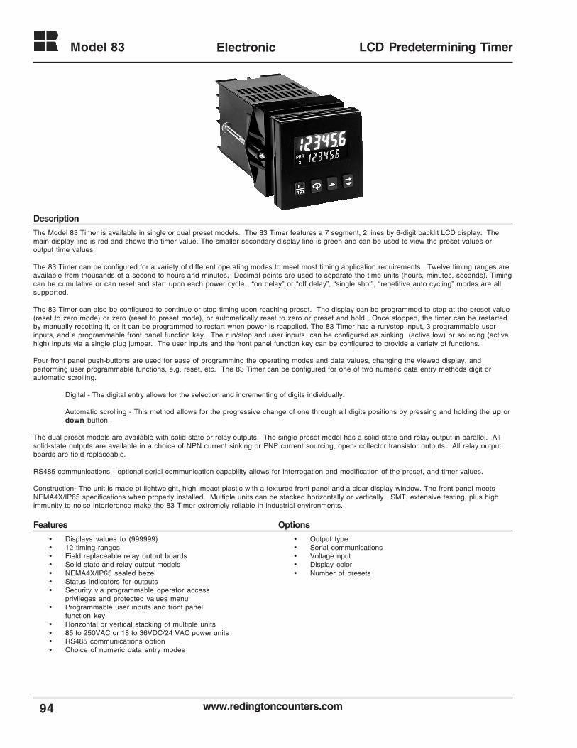
www.redingtoncounters.com
Model 83
94
Electronic LCD Predetermining Timer
The Model 83 Timer is available in single or dual preset models. The 83 Timer features a 7 segment, 2 lines by 6-digit backlit LCD display. Themain display line is red and shows the timer value. The smaller secondary display line is green and can be used to view the preset values oroutput time values.
The 83 Timer can be configured for a variety of different operating modes to meet most timing application requirements. Twelve timing ranges areavailable from thousands of a second to hours and minutes. Decimal points are used to separate the time units (hours, minutes, seconds). Timingcan be cumulative or can reset and start upon each power cycle. “on delay” or “off delay”, “single shot”, “repetitive auto cycling” modes are allsupported.
The 83 Timer can also be configured to continue or stop timing upon reaching preset. The display can be programmed to stop at the preset value(reset to zero mode) or zero (reset to preset mode), or automatically reset to zero or preset and hold. Once stopped, the timer can be restartedby manually resetting it, or it can be programmed to restart when power is reapplied. The 83 Timer has a run/stop input, 3 programmable userinputs, and a programmable front panel function key. The run/stop and user inputs can be configured as sinking (active low) or sourcing (activehigh) inputs via a single plug jumper. The user inputs and the front panel function key can be configured to provide a variety of functions.
Four front panel push-buttons are used for ease of programming the operating modes and data values, changing the viewed display, andperforming user programmable functions, e.g. reset, etc. The 83 Timer can be configured for one of two numeric data entry methods digit orautomatic scrolling.
Digital - The digital entry allows for the selection and incrementing of digits individually.
Automatic scrolling - This method allows for the progressive change of one through all digits positions by pressing and holding the up ordown button.
The dual preset models are available with solid-state or relay outputs. The single preset model has a solid-state and relay output in parallel. Allsolid-state outputs are available in a choice of NPN current sinking or PNP current sourcing, open- collector transistor outputs. All relay outputboards are field replaceable.
RS485 communications - optional serial communication capability allows for interrogation and modification of the preset, and timer values.
Construction- The unit is made of lightweight, high impact plastic with a textured front panel and a clear display window. The front panel meetsNEMA4X/IP65 specifications when properly installed. Multiple units can be stacked horizontally or vertically. SMT, extensive testing, plus highimmunity to noise interference make the 83 Timer extremely reliable in industrial environments.
• Displays values to (999999)• 12 timing ranges• Field replaceable relay output boards• Solid state and relay output models• NEMA4X/IP65 sealed bezel• Status indicators for outputs• Security via programmable operator access
privileges and protected values menu• Programmable user inputs and front panel
function key• Horizontal or vertical stacking of multiple units• 85 to 250VAC or 18 to 36VDC/24 VAC power units• RS485 communications option• Choice of numeric data entry modes
• Output type• Serial communications• Voltage input• Display color• Number of presets
Features Options
Description
95www.redingtoncounters.com
Model 83 Electronic LCD Predetermining Timer
Specifications
Display: 2 line by 6 digits LCD display, negative imagetransmissive with RED (top line) and GREEN(bottom line) backlighting. Positive image reflectivedisplay units are non-stock available.
Main: 0.3" (7.6mm) high digits Secondary: 0.2" (5mm) high digitsAnnunciators:
Value: PRS, 1, and 2Output: 01 and 02
POWER REQUIREMENTS:AC Versions
AC Power: 85 to 250 VAC, 50/60Hz, 9VA max.DC power: 11 to 14 VDC @ 159 mA max. (Non PNP
output models)Note: Models with PNP current sourcing outputs must be
powered from AC
DC VersionsDC Power: 18 to 36 VDC: 5.5 W max.AC Power: 24 VAC +/- 10%: 50/60 Hz: 7VA max.
Note: The 10% tolerance range on AC input voltage must bestrictly adhered to> DO NOT EXCEED 26.4 VAC
PEAK (START-UP CURRENT)AC or DC Power: 500mA peak start-up current for 10 msec.max.
DC OUT/ VSCR IN-terminal 10For units that do not have PNP current sourcing outputs, this terminalprovides a DC output for sensor power (+ 12 VDC +/-15%). Themaximum sensor current is 100mA. For units with PNP current sourcingoutputs this terminal serves a dual purpose depending on the applicationPNP output voltage level and current requirements.
1. The terminal may be used as a +12 VDC output for sensorpower. In this case, the PNP output voltage level will be+12 VDC (+/-15%). A maximum of 100 mA is available forthe combination of sensor and PNP output sourcingcurrent.
2. If a higher PNP output voltage level or additional outputsourcing current is needed, an external DC supply may beconnected between the “DC OUT” ( V SRC IN) and“COMM.” terminals. This supply will determine the PNPoutput voltage level, and must be in the same range of +13to +30 VDC.An external DC supply can also provide the additionaloutput sourcing current required in applications wheretwo or more PNP outputs are “ON” simultaneously.However, the maximum current range of 100mA perindividual output must not be exceeded, regardless ofexternal supply capacity.
3. MEMORY: Nonvolatile FRAM retains all program parameters andTimer values.
4. SENSOR POWER: +12 VDC (+/- 15%) @ 100mA max.
5. INPUTS: Run/Stop, Usr. In1, Usr. In2, and Usr. In3.Configurable as current sinking (active low), orcurrent sourcing (active high) inputs via a singleplug jumper.
Current Sinking: (active low) :VIL = 1.5 VDC max. 22 K ohm pull-ups to 5 VDC
Current Sourcing: (active high): VIH = 3.5 min.VIN max. = 30 VDC; 22K ohm pull-down.
Run/Stop Response Time : 250 microseconds max.
User Input Response Time: 5 msec. max.
6. TIME ACCURACY: +/- 0.01%
7. OUTPUTS: ( Output type and quantity model dependent) Solid-State:
NPN Open Collector:ISNK = 100mA max. @ VOL = 1.1 VDC max.;VOH = 30 VDC max.
PNP Open Collector:ISRC = 100mA max. ( See note) ; VOH = 12 VDC +/-15%( using internal supply); VOH = 13 to 30 VDC ( usingexternal supply).
Note: The internal supply of the 83 Timer can provide a total of100 mA for the combination of sensor current and PNP outputsourcing current. The supply voltage is +12 VDC (+/-5 %),which will be the PNP output voltage level when using only theinternal supply.If additional PNP output sourcing current or a higher outputvoltage level is desired, an external DC supply may beconnected between the “ DC Out/In” and “Comm” terminals.This supply will determine the PNP output voltage level, andmust be in range of +13 to 30 VDC.An external supply can provide the additional output sourcingcurrent required in applications where two or more outputs are“ON” simultaneously. However, the maximum rating of 100mAper individual output must not be exceeded, regardless ofexternal supply capacity.
Relay: Form A contact, rating = 5 A @ 250 VAC, 30 VDC (resistiveload) 1/10 HP @ 120 VAC (inductive load).Relay Life Expectancy:
100,000 cycles min. at max. load rating.Programmable Timed Output:
User selectable output time resolutions.0.01 Second Resolution: 0.01 to 99.99 sec., +/-
0.01% +10 msec max.0.1 Second Resolution: 0.1 to 999.9 sec. +/- 0.01
% +100 msec max.
8. RS485 SERIAL COMMUNICATIONS (Optional):Up to 32 units can be connected.Baud Rate: Programmable from 1200 to 9600 baud.Address: Programmable from 0 to 99Data Format: 10 Bit Frame, 1 start bit , 7 or 8 data bits, 1 orno Parity bit, and 1 stop bit.Parity: Programmable for Odd (7 data bits), Even ( 7 data bits)or None ( 8 data bits).
9. CERTIFICATIONS AND COMPLIANCES:UL Recognized Component, File # E195514Recognized to U.S. and Canadian requirements under the ComponentRecognition Program of Underwriters Laboratories, Inc.
CE COMPLIANT :ELECTROMAGNETIC COMPATIBILITY
Immunity to EN 50082-2electrostatic discharge EN 61000-4-2electromagnetic RF fields EN 61000-4-3fast transients EN 61000-4-4RF conducted interference EN 61000-4-6simulation of cordless phone ENV50204
Emissions to EN 50081-2RF interference EN 55011 enclosure class A
10. ENVIRONMENTAL CONDITIONS:Operating Temperature: +32°F to +122°F [0°C to +50°C]Storage Temperature: -40°F to +158°F [-40°C to +70°C]
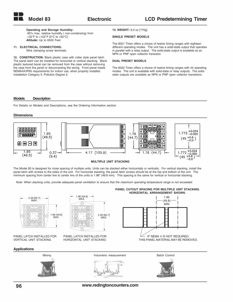
www.redingtoncounters.com
Model 83
96
Electronic LCD Predetermining Timer
Operating and Storage Humidity: 85% max. relative humidity ( non-condensing) from +32°F to +122°F [0°C to +50°C]Altitude: Up to 6500 Feet
11. ELECTRICAL CONNECTIONS:Wire clamping screw terminals.
12. CONSTRUCTION: Black plastic case with collar style panel latch.The panel latch can be installed for horizontal or vertical stacking. Blackplastic textured bezel can be removed from the case without removingthe case from the panel or disconnecting the wiring. Front panel meetsNEMA4X/IP65 requirements for indoor use, when properly installed.Installation Category II, Pollution Degree 2.
13. WEIGHT: 6.0 oz [170g]
SINGLE PRESET MODELS
The 8321 Timer offers a choice of twelve timing ranges with eighteendifferent operating modes. The unit has a solid-state output that operatesin parallel with a relay output. The solid-state output is available as anNPN or PNP open collector transistor.
DUAL PRESET MODELS
The 8322 Timer offers a choice of twelve timing ranges with 44 operatingmodes. The unit is available with solid-state or relay outputs. The solid-state outputs are available as NPN or PNP open collector transistors.
For Details on Models and Descriptions, see the Ordering Information section
1.96 [49.8]MAX.
2.39 [60.7]MAX.
2.39 [60.7]MAX.
1.96 [49.8]MAX.
PANEL LATCH INSTALLED FORVERTICAL UNIT STACKING
PANEL LATCH INSTALLED FORHORIZONTAL UNIT STACKING
PANEL CUTOUT SPACING FOR MULTIPLE UNIT STACKING.HORIZONTAL ARRANGEMENT SHOWN.
IF NEMA 4 IS NOT REQUIRED,THIS PANEL MATERIAL MAY BE REMOVED.
1212121212121212
1212121212121212
1.96(49.8)MIN
MULTIPLE UNIT STACKING
The Model 83 is designed for close spacing of multiple units. Units can be stacked either horizontally or vertically. For vertical stacking, install thepanel latch with screws to the sides of the unit. For horizontal stacking, the panel latch screws should be at the top and bottom of the unit. Theminimum spacing from center line to center line of the units is 1.96” (49.8 mm). This spacing is the same for vertical or horizontal stacking.
Note: When stacking units, provide adequate panel ventilation to ensure that the maximum operating temperature range is not exceeded.
Applications
Models Description
Dimensions
Mixing Batch ControlVolumetric measurement
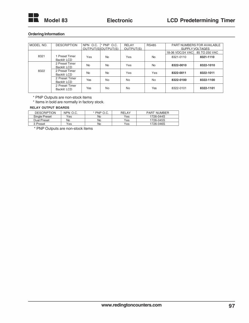
97www.redingtoncounters.com
Model 83 Electronic LCD Predetermining Timer
MODEL NO. DESCRIPTION NPN O.C. * PNP O.C. RELAY RS485 PART NUMBERS FOR AVAILABLEOUTPUT(S) OUTPUT(S) OUTPUT(S) SUPPLY VOLTAGES
18-36 VDC/24 VAC 85 TO 250 VAC8321 1 Preset Timer Yes No Yes No 8321-0110 8321-1110
Backlit LCD2 Preset Timer No No Yes No 8322-0010 8322-1010Backlit LCD
8322 2 Preset TimerNo No Yes Yes 8322-0011 8322-1011Backlit LCD
2 Preset Timer Yes No No No 8322-0100 8322-1100Backlit LCD2 Preset Timer
Yes No No Yes 8322-0101 8322-1101Backlit LCD
Ordering Information
* PNP Outputs are non-stock items
RELAY OUTPUT BOARDS
DESCRIPTION NPN O.C. * PNP O.C. RELAY PART NUMBERSingle Preset Yes No Yes 1726-044SDual Preset No No Yes 1726-045S3 Preset Yes No Yes 1726-046S
* PNP Outputs are non-stock items* Items in bold are normally in factory stock.
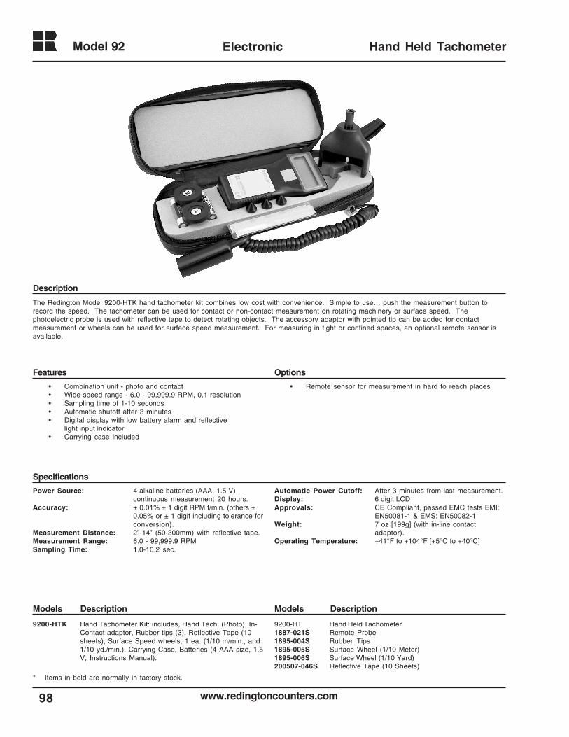
www.redingtoncounters.com
Model 92
98
Electronic Hand Held Tachometer
The Redington Model 9200-HTK hand tachometer kit combines low cost with convenience. Simple to use… push the measurement button torecord the speed. The tachometer can be used for contact or non-contact measurement on rotating machinery or surface speed. Thephotoelectric probe is used with reflective tape to detect rotating objects. The accessory adaptor with pointed tip can be added for contactmeasurement or wheels can be used for surface speed measurement. For measuring in tight or confined spaces, an optional remote sensor isavailable.
Power Source: 4 alkaline batteries (AAA, 1.5 V)continuous measurement 20 hours.
Accuracy: ± 0.01% ± 1 digit RPM f/min. (others ±0.05% or ± 1 digit including tolerance forconversion).
Measurement Distance: 2”-14” (50-300mm) with reflective tape.Measurement Range: 6.0 - 99,999.9 RPMSampling Time: 1.0-10.2 sec.
Automatic Power Cutoff: After 3 minutes from last measurement.Display: 6 digit LCDApprovals: CE Compliant, passed EMC tests EMI:
EN50081-1 & EMS: EN50082-1Weight: 7 oz [199g] (with in-line contact
adaptor).Operating Temperature: +41°F to +104°F [+5°C to +40°C]
• Combination unit - photo and contact• Wide speed range - 6.0 - 99,999.9 RPM, 0.1 resolution• Sampling time of 1-10 seconds• Automatic shutoff after 3 minutes• Digital display with low battery alarm and reflective
light input indicator• Carrying case included
• Remote sensor for measurement in hard to reach places
9200-HTK Hand Tachometer Kit: includes, Hand Tach. (Photo), In-Contact adaptor, Rubber tips (3), Reflective Tape (10sheets), Surface Speed wheels, 1 ea. (1/10 m/min., and1/10 yd./min.), Carrying Case, Batteries (4 AAA size, 1.5V, Instructions Manual).
9200-HT Hand Held Tachometer1887-021S Remote Probe1895-004S Rubber Tips1895-005S Surface Wheel (1/10 Meter)1895-006S Surface Wheel (1/10 Yard)200507-046S Reflective Tape (10 Sheets)
Models DescriptionModels Description
Specifications
Features Options
Description
* Items in bold are normally in factory stock.
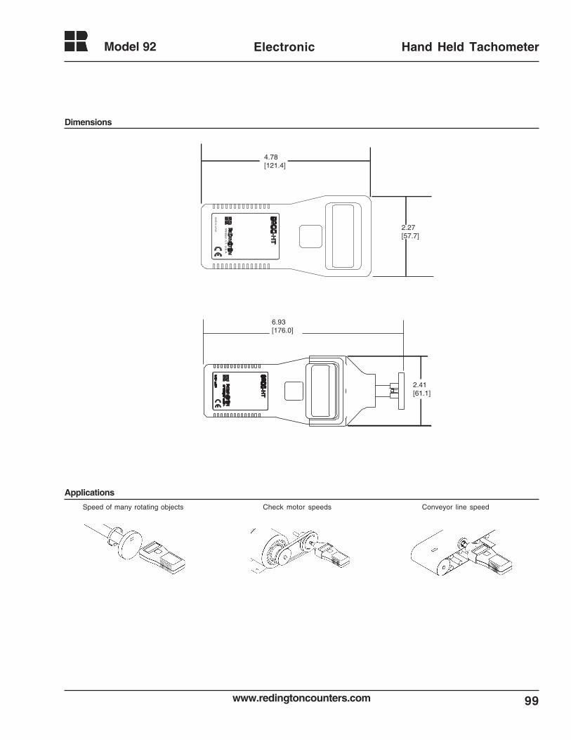
99www.redingtoncounters.com
Model 92 Electronic Hand Held Tachometer
6.93[176.0]
2.41[61.1]
Check motor speedsSpeed of many rotating objects Conveyor line speed
2.27[57.7]
4.78[121.4]
Dimensions
Applications
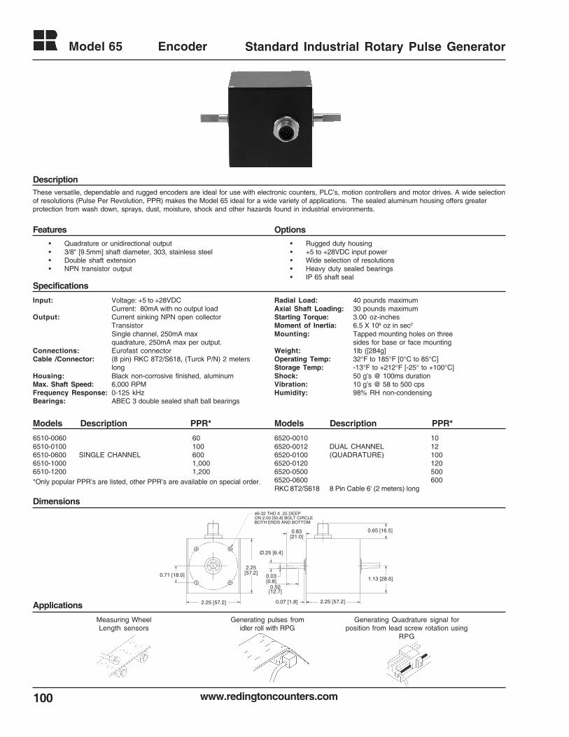
www.redingtoncounters.com
Model 65
100
Encoder Standard Industrial Rotary Pulse Generator
These versatile, dependable and rugged encoders are ideal for use with electronic counters, PLC’s, motion controllers and motor drives. A wide selectionof resolutions (Pulse Per Revolution, PPR) makes the Model 65 ideal for a wide variety of applications. The sealed aluminum housing offers greaterprotection from wash down, sprays, dust, moisture, shock and other hazards found in industrial environments.
Description
Features Options
Specifications
Input: Voltage: +5 to +28VDCCurrent: 80mA with no output load
Output: Current sinking NPN open collectorTransistorSingle channel, 250mA maxquadrature, 250mA max per output.
Connections: Eurofast connectorCable /Connector: (8 pin) RKC 8T2/S618, (Turck P/N) 2 meters
longHousing: Black non-corrosive finished, aluminumMax. Shaft Speed: 6,000 RPMFrequency Response: 0-125 kHzBearings: ABEC 3 double sealed shaft ball bearings
Models Description PPR*Models Description PPR*
Dimensions
Applications
• Quadrature or unidirectional output• 3/8" [9.5mm] shaft diameter, 303, stainless steel• Double shaft extension• NPN transistor output
Radial Load: 40 pounds maximumAxial Shaft Loading: 30 pounds maximumStarting Torque: 3.00 oz-inchesMoment of Inertia: 6.5 X 10⁶ oz in sec2
Mounting: Tapped mounting holes on threesides for base or face mounting
Weight: 1lb ([284g]Operating Temp: 32°F to 185°F [0°C to 85°C]Storage Temp: -13°F to +212°F [-25° to +100°C]Shock: 50 g’s @ 100ms durationVibration: 10 g’s @ 58 to 500 cpsHumidity: 98% RH non-condensing
6510-0060 606510-0100 1006510-0600 SINGLE CHANNEL 6006510-1000 1,0006510-1200 1,200
6520-0010 106520-0012 DUAL CHANNEL 126520-0100 (QUADRATURE) 1006520-0120 1206520-0500 5006520-0600 600RKC 8T2/S618 8 Pin Cable 6' (2 meters) long
*Only popular PPR’s are listed, other PPR’s are available on special order.
2.25 [57.2]2.25 [57.2] 0.07 [1.8]
2.25[57.2]
Ø.25 [6.4]
#6-32 THD X .25 DEEPON 2.00 [50.8] BOLT CIRCLEBOTH ENDS AND BOTTOM
1.13 [28.6]
0.65 [16.5]
0.71 [18.0]
0.83[21.0]
0.50[12.7]
0.03[0.8]
• Rugged duty housing• +5 to +28VDC input power• Wide selection of resolutions• Heavy duty sealed bearings• IP 65 shaft seal
Measuring WheelLength sensors
Generating pulses fromidler roll with RPG
Generating Quadrature signal forposition from lead screw rotation using
RPG
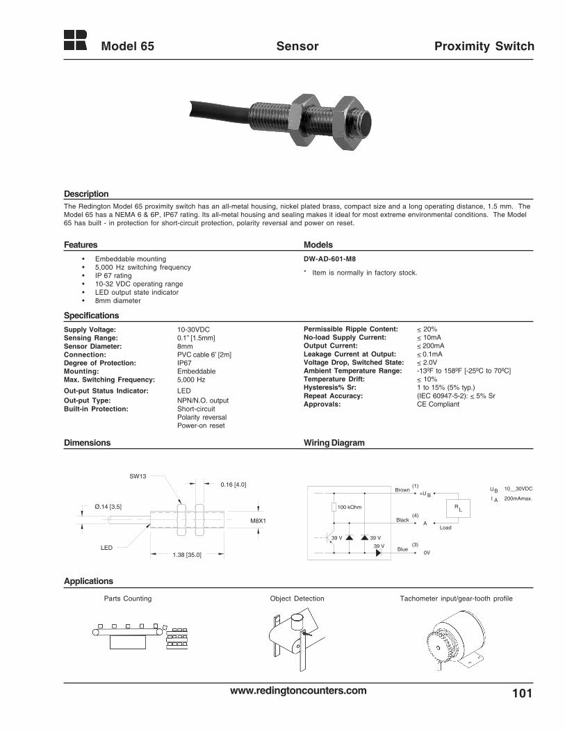
101www.redingtoncounters.com
Model 65 Sensor Proximity Switch
Description
Specifications
Applications
Parts Counting Object Detection Tachometer input/gear-tooth profile
The Redington Model 65 proximity switch has an all-metal housing, nickel plated brass, compact size and a long operating distance, 1.5 mm. TheModel 65 has a NEMA 6 & 6P, IP67 rating. Its all-metal housing and sealing makes it ideal for most extreme environmental conditions. The Model65 has built - in protection for short-circuit protection, polarity reversal and power on reset.
• Embeddable mounting• 5,000 Hz switching frequency• IP 67 rating• 10-32 VDC operating range• LED output state indicator• 8mm diameter
Supply Voltage: 10-30VDCSensing Range: 0.1’’ [1.5mm]Sensor Diameter: 8mmConnection: PVC cable 6’ [2m]Degree of Protection: IP67Mounting: EmbeddableMax. Switching Frequency: 5,000 Hz
Out-put Status Indicator: LEDOut-put Type: NPN/N.O. outputBuilt-in Protection: Short-circuit
Polarity reversalPower-on reset
Features
Permissible Ripple Content: < 20%No-load Supply Current: < 10mAOutput Current: < 200mALeakage Current at Output: < 0.1mAVoltage Drop, Switched State: < 2.0VAmbient Temperature Range: -13ºF to 158ºF [-25ºC to 70ºC]Temperature Drift: < 10%Hysteresis% Sr: 1 to 15% (5% typ.)Repeat Accuracy: (IEC 60947-5-2): < 5% SrApprovals: CE Compliant
Dimensions Wiring Diagram
Models
DW-AD-601-M8
39 V 39 V
39 VBlue
Black
Brown+U
A
0V
R100 kOhm L
(1)
(4)
(3)
B
Load
UB 10__30VDC
200mAmax.I A
* Item is normally in factory stock.
1.38 [35.0]
M8X1
0.16 [4.0]
Ø.14 [3.5]
SW13
LED
www.redingtoncounters.com
Glossary
102
TERM DEFINITION
A-B Input The B input pulses are subtracted from the Ainput pulses.This type of input is used on counters &indicators.
A+B Input The A and B input pulses are added together.This type input is used on counters andposition indicators.
AC Alternating current; an electric current thatreverses its direction at recurring intervals.
Accuracy The closeness of an indication or reading of ameasurement device to the actual value of thequantity being measured. Usually expressedas a ± percent of full scale output or reading,
Add/Subtract The ability to count up and down.
Ammeter An instrument used to measure current.
Analog A signal that varies continuously in amplitudewithout interruption.
Analog Output A circuit whose output is a reproduction of itsinput..
Automatic Reset A reset that is based on a pre-programmedevent. Used in counters or timers.
Baud Rate The rate at which each bit is transferred to andfrom a device.
Bidirectional The counter or encoder can count in bothdirections.
Bit This is the name for a binary digit.
Byte A sequence of adjacent binary digits operatedon as a single unit. A byte is eight bits inlength.
Capacitor An assembly of one or more pairs of conduc-tors separated by insulators used to store anelectrical charge. The capacitance of ismeasured in FARADS or parts thereof.
CE (Conformite Europeeene mark) A symbol (CE)applied to finished products and machineryindicating it meets all applicable European
Directives. For electrical and electronic“finished products”, such as electronic andelectromechanical counters, hour meters,these include the Low Voltage Directive and,where relevant, the Electromagnetic Compat-ibility (EMC) Directive.
Color code The ANSI established color code for thethermocouple wires in the negative lead isalways RED. Color code for base metalthermocouples is YELLOW for Type K, BLACKfor type J, PURPLE for Type E and BLUE forType T.
Control point The set point at which a system is to bemaintained.
CSA (Canadian Standards Association) An inde-pendent Canadian testing and standards-making org. similar to Underwriters Laborato-ries (UL) in the USA. “CSA -certified “ productsmeet relevant CSA electrical and safetystandards.
Current sinking /Open collectorIn the “off” state the transistor can be viewed asan open switch. When energized it turns “ON”,connecting the output to the ground return lead.The transistor is usually NPN.
Current sourcing/Open collectorIn the “off” state the transistor can be viewed asan open switch. When energized it turns “ON”,connecting the output to the voltage supplylead. The transistor is usually PNP.
DC Direct current: An electric current flowing in onedirection only and substantially constant invalue.
Die A single piece of silicon onto which a semicon-ductor circuit has been fabricated.(Plural= Dice)
Digit A measurement of the display span of a panelmeter. By convention, a full digit can assumeany value from 0 through 9, a 1/2 digit willdisplay a 1 and overload at 2. For example, thefull scale value of a 3 1/2 digit display is 1999.
Digital Volt Meter A device used to measure voltages and give adigital read out.
103www.redingtoncounters.com
Glossary
DIN A Deutsche Industrial Norme standard. SomeRCI products utilize these dimensionalstandards.
Direct drive Refers to the gear ratio in a mechanicalcounter one revolution of the input shaftequals 10 counts.
Drift A change of a reading or a set point value overlong periods due to several factors includingchange in ambient temperature, time, and linevoltage.
EMF Electromotive force. A rise in (electrical)potential energy. The principle unit is the volt.
EMI Electromagnetic interference.
Encoder An electromechanical device that translatesmechanical motion into electrical pulses.
FRAM Nonvolatile memory. Uses the ferroelectriceffect for a storage mechanism.
Hertz (Hz) Units in which the frequency is expressed.Synonymous with cycles per second.
Hysteresis In an ON-OFF controller it defines the differ-ence between the two switching points. Itrefers to the difference between the value atwhich the alarm switches on and the value atwhich the alarm switches off again.
Incremental encoderA device that provides a series of periodicsignals due to mechanical motion. The numberof successive cycles corresponds to theresolvable mechanical increments of motion.
Impedance The total opposition to electrical flow (resistiveplus reactive).
Input impedance The resistance of a panel meter as seen fromthe source. In the case of a voltmeter, thisresistance has to be taken into account whenthe source impedance is high; in the case ofan ammeter, when the impedance is low.
Joule The basic unit of thermal energy.
LCD (Liquid Crystal Display) A liquid crystal displayis made of two glass plates, each with atransparent conductive coating, which
sandwich the crystal material. When a voltageis applied molecules in the liquid crystal alignthemselves with the field generated preventinglight from passing, creating a display segment.The pattern on the display forms the requiredpicture or numeral.
LED (Light Emitting Diode) A diode which emits lightof a particular wavelength when a current ispassed through it.
LSI ( Large Scale Integration) Used to refer tointegrated circuits which today have fromthousands to millions of components on onesilicon chip.
Load The electrical demand of a process expressedas power (watts), current (amps), or resistance(ohms).
Maximum operating temperatureThe maximum temperature at which aninstrument can be operated and still be withinoperating specifications.
Micro A prefix meaning one millionth.
Milli A prefix meaning one thousandth.
Multiplication Any technique used to obtain an outputresolution different from the line count.
Nano A prefix meaning one thousand-millionth.
Noise An unwanted electrical interference on thesignal wires.
OHM The unit of electrical resistance. A constantvoltage of one volt across a resistance of oneOHM will produce a current in it of oneampere. OHMS LAW V=IR
Ohmmeter An instrument used to measure resistance.
Optical Isolator Sometimes referred to as an optocoupler. Adevice that isolates two stages of a circuit;e.g.., input and output from each other so thatinterference in one will not effect the other.
Optical Isolation A method of reducing noise interferencebetween two circuits using optical isolators.
Predetermining The counter can provide an “output” signal at apredetermined count or time.
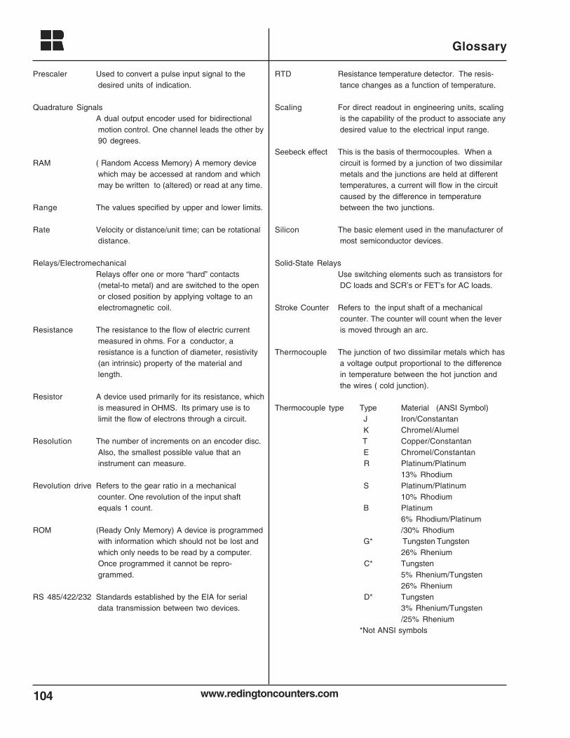
www.redingtoncounters.com
Glossary
104
Prescaler Used to convert a pulse input signal to thedesired units of indication.
Quadrature SignalsA dual output encoder used for bidirectionalmotion control. One channel leads the other by90 degrees.
RAM ( Random Access Memory) A memory devicewhich may be accessed at random and whichmay be written to (altered) or read at any time.
Range The values specified by upper and lower limits.
Rate Velocity or distance/unit time; can be rotationaldistance.
Relays/ElectromechanicalRelays offer one or more “hard” contacts(metal-to metal) and are switched to the openor closed position by applying voltage to anelectromagnetic coil.
Resistance The resistance to the flow of electric currentmeasured in ohms. For a conductor, aresistance is a function of diameter, resistivity(an intrinsic) property of the material andlength.
Resistor A device used primarily for its resistance, whichis measured in OHMS. Its primary use is tolimit the flow of electrons through a circuit.
Resolution The number of increments on an encoder disc.Also, the smallest possible value that aninstrument can measure.
Revolution drive Refers to the gear ratio in a mechanicalcounter. One revolution of the input shaftequals 1 count.
ROM (Ready Only Memory) A device is programmedwith information which should not be lost andwhich only needs to be read by a computer.Once programmed it cannot be repro-grammed.
RS 485/422/232 Standards established by the EIA for serialdata transmission between two devices.
RTD Resistance temperature detector. The resis-tance changes as a function of temperature.
Scaling For direct readout in engineering units, scalingis the capability of the product to associate anydesired value to the electrical input range.
Seebeck effect This is the basis of thermocouples. When acircuit is formed by a junction of two dissimilarmetals and the junctions are held at differenttemperatures, a current will flow in the circuitcaused by the difference in temperaturebetween the two junctions.
Silicon The basic element used in the manufacturer ofmost semiconductor devices.
Solid-State RelaysUse switching elements such as transistors forDC loads and SCR’s or FET’s for AC loads.
Stroke Counter Refers to the input shaft of a mechanicalcounter. The counter will count when the leveris moved through an arc.
Thermocouple The junction of two dissimilar metals which hasa voltage output proportional to the differencein temperature between the hot junction andthe wires ( cold junction).
Thermocouple type Type Material (ANSI Symbol) J Iron/Constantan K Chromel/Alumel T Copper/Constantan E Chromel/Constantan R Platinum/Platinum
13% Rhodium S Platinum/Platinum
10% Rhodium B Platinum
6% Rhodium/Platinum/30% Rhodium
G* Tungsten Tungsten26% Rhenium
C* Tungsten5% Rhenium/Tungsten26% Rhenium
D* Tungsten3% Rhenium/Tungsten/25% Rhenium
*Not ANSI symbols
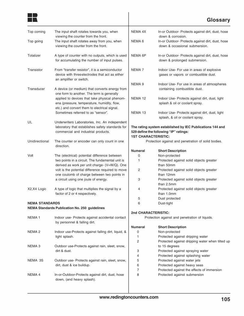
105www.redingtoncounters.com
Glossary
Top coming The input shaft rotates towards you, whenviewing the counter from the front.
Top going The input shaft rotates away from you, whenviewing the counter from the front.
Totalizer A type of counter with no outputs, which is usedfor accumulating the number of input pulses.
Transistor From “transfer resistor”, it is a semiconductordevice with threeelectrodes that act as eitheran amplifier or switch.
Transducer A device (or medium) that converts energy fromone form to another. The term is generallyapplied to devices that take physical phenom-ena (pressure, temperature, humidity, flow,etc.) and convert them to electrical signal.Sometimes referred to as “sensor”.
UL Underwriters Laboratories, Inc. An independentlaboratory that establishes safety standards forcommercial and industrial products.
Unidirectional The counter or encoder can only count in onedirection.
Volt The (electrical) potential difference betweentwo points in a circuit. The fundamental unit isderived as work per unit charge- (V=W/Q). Onevolt is the potential difference required to moveone coulomb of charge between two points ina circuit using one joule of energy.
X2,X4 Logic A type of logic that multiplies the signal by afactor of 2 or 4 respectively.
NEMA STANDARDSNEMA Standards Publication No. 250 guidelines
NEMA 1 Indoor use- Protects against accidental contactby personnel & falling dirt.
NEMA 2 Indoor use-Protects against falling dirt, liquid, &light splash.
NEMA 3 Outdoor use-Protects against rain, sleet, snow,dirt & dust.
NEMA 3S Outdoor use- Protects against rain, sleet, snow,dirt, dust & ice buildup.
NEMA 4 In-or-Outdoor-Protects against dirt, dust, hosedown, (and heavy splash).
NEMA 4X In-or Outdoor- Protects against dirt, dust, hosedown & corrosion.
NEMA 6 In-or Outdoor- Protects against dirt, dust, hosedown & occasional submersion.
NEMA 6P In-or Outdoor- Protects against dirt, dust, hosedown & prolonged submersion.
NEMA 7 Indoor Use- For use in areas of explosivegases or vapors or combustible dust.
NEMA 9 Indoor Use- For use in areas of atmospherescontaining combustible dust.
NEMA 12 Indoor Use- Protects against dirt, dust, lightsplash & oil or coolant spray.
NEMA 13 Indoor Use- Protects against dirt, dust, lightsplash, & oil or coolant spray.
The rating system established by IEC Publications 144 and529 define the following “IP” ratings:1ST CHARACTERISTIC:
Protection against and penetration of solid bodies.
Numeral Short Description0 Non-protected1 Protected against solid objects greater
than 50mm2 Protected against solid objects greater
than 12mm3 Protected against solid objects greater
than 2.5mm4 Protected against solid objects greater
than 1.0mm5 Dust protected6 Dust-tight
2nd CHARACTERISTIC:Protection against and penetration of liquids.
Numeral Short Description0 Non-protected1 Protected against dripping water2 Protected against dripping water when tilted up
to 15 degrees3 Protected against spraying water4 Protected against splashing water5 Protected against water jets6 Protected against heavy seas7 Protected against the effects of immersion8 Protected against submersion
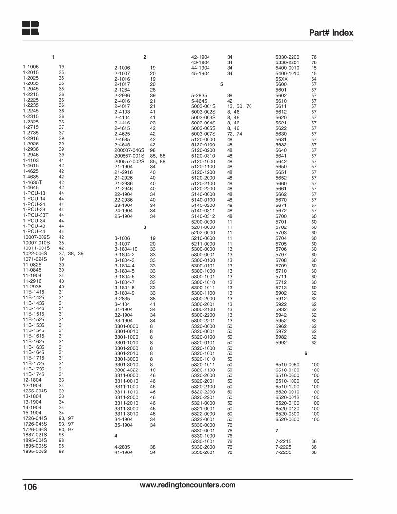
www.redingtoncounters.com106
Part# Index
1
1-1006 191-2015 351-2025 351-2035 351-2045 351-2215 361-2225 361-2235 361-2245 361-2315 361-2325 361-2715 371-2735 371-2916 391-2926 391-2936 391-2946 391-4103 411-4615 421-4625 421-4635 421-4635T 421-4645 421-PCU-13 441-PCU-14 441-PCU-24 441-PCU-33 441-PCU-33T 441-PCU-34 441-PCU-43 441-PCU-44 4410007-009S 4210007-010S 3510011-001S 421022-006S 37, 38, 391071-024S 1911-0825 3011-0845 3011-1904 3411-2916 4011-2936 4011B-1415 3111B-1425 3111B-1435 3111B-1445 3111B-1515 3111B-1525 3111B-1535 3111B-1545 3111B-1615 3111B-1625 3111B-1635 3111B-1645 3111B-1715 3111B-1725 3111B-1735 3111B-1745 3112-1804 3312-1904 341255-004S 3913-1804 3313-1904 3414-1904 3415-1904 341726-044S 93, 971726-045S 93, 971726-046S 93, 971887-021S 981895-004S 981895-005S 981895-006S 98
2
2-1006 192-1007 202-1016 192-1017 202-1284 282-2936 392-4016 212-4017 212-4103 412-4104 412-4416 232-4615 422-4625 422-4635 422-4645 42200507-046S 98200557-001S 85, 88200557-002S 85, 8821-1904 3421-2916 4021-2926 4021-2936 4021-2946 4022-1904 3422-2936 4023-1904 3424-1904 3425-1904 34
3
3-1006 193-1007 203-1804-10 333-1804-2 333-1804-3 333-1804-4 333-1804-5 333-1804-6 333-1804-7 333-1804-8 333-1804-9 333-2835 383-4104 4131-1904 3432-1904 3433-1904 343301-0000 83301-0010 83301-1000 83301-1010 83301-2000 83301-2010 83301-3000 83301-3010 83302-4322 103311-0000 463311-0010 463311-1000 463311-1010 463311-2000 463311-2010 463311-3000 463311-3010 4634-1904 3435-1904 34
4
4-2835 3841-1904 34
42-1904 3443-1904 3444-1904 3445-1904 34
5
5-2835 385-4645 425003-001S 13, 50, 765003-002S 8, 465003-003S 8, 465003-004S 8, 465003-005S 8, 465003-007S 72, 745120-0000 485120-0100 485120-0200 485120-0310 485120-1000 485120-1100 485120-1200 485120-2000 485120-2100 485120-2200 485140-0000 485140-0100 485140-0200 485140-0311 485140-0312 485200-0000 115201-0000 115202-0000 115210-0000 115211-0000 115300-0000 135300-0001 135300-0100 135300-0101 135300-1000 135300-1001 135300-1010 135300-1011 135300-1100 135300-2000 135300-2001 135300-2100 135300-2200 135300-2201 135320-0000 505320-0001 505320-0100 505320-0101 505320-1000 505320-1001 505320-1010 505320-1011 505320-1100 505320-2000 505320-2001 505320-2100 505320-2200 505320-2201 505321-0000 505321-0001 505322-0000 505322-0001 505330-0000 765330-0001 765330-1000 765330-1001 765330-2000 765330-2001 76
5330-2200 765330-2201 765400-0010 155400-1010 1555XX 545600 575601 575602 575610 575611 575612 575620 575621 575622 575630 575631 575632 575640 575641 575642 575650 575651 575652 575660 575661 575662 575670 575671 575672 575700 605701 605702 605703 605704 605705 605706 605707 605708 605709 605710 605711 605712 605713 605902 625912 625922 625932 625942 625952 625962 625972 625982 625992 62
6
6510-0060 1006510-0100 1006510-0600 1006510-1000 1006510-1200 1006520-0010 1006520-0012 1006520-0100 1006520-0120 1006520-0500 1006520-0600 100
7
7-2215 367-2225 367-2235 36
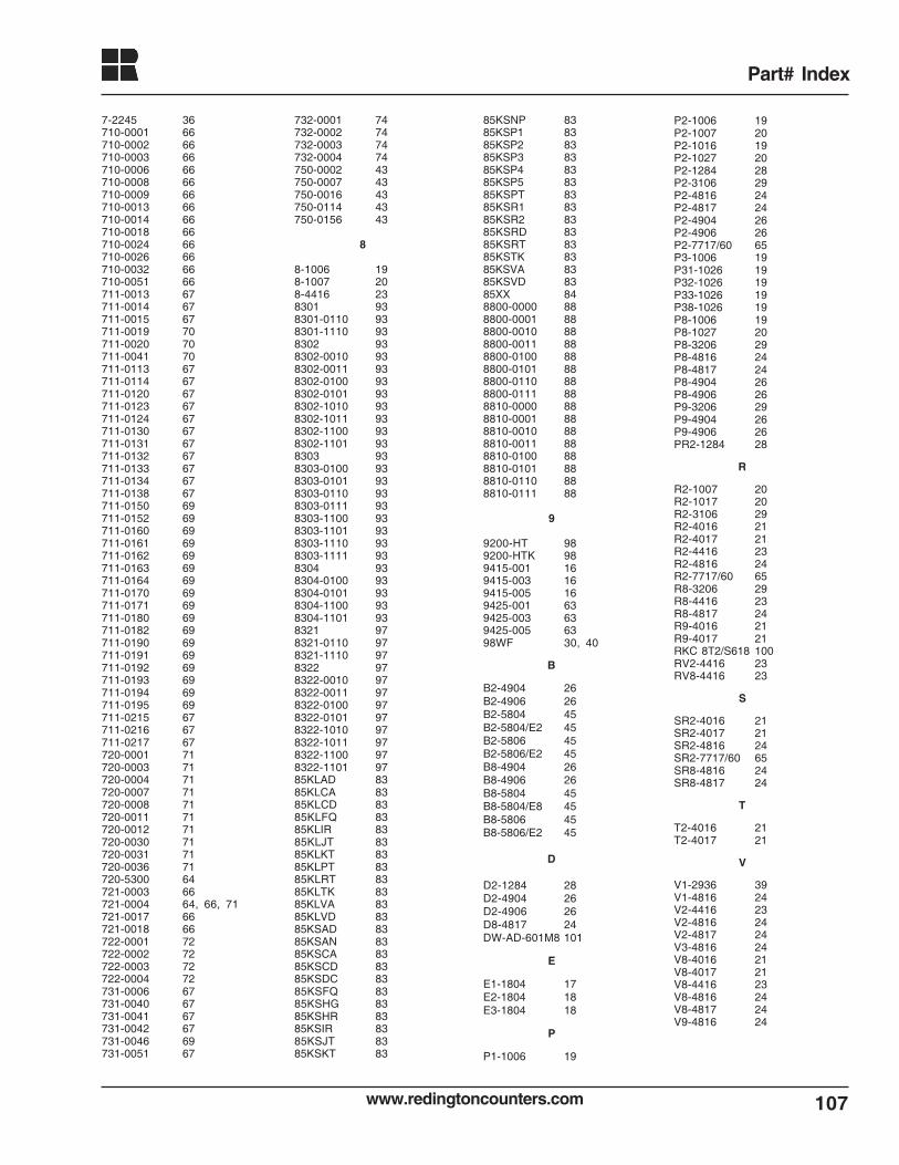
www.redingtoncounters.com 107
Part# Index
7-2245 36710-0001 66710-0002 66710-0003 66710-0006 66710-0008 66710-0009 66710-0013 66710-0014 66710-0018 66710-0024 66710-0026 66710-0032 66710-0051 66711-0013 67711-0014 67711-0015 67711-0019 70711-0020 70711-0041 70711-0113 67711-0114 67711-0120 67711-0123 67711-0124 67711-0130 67711-0131 67711-0132 67711-0133 67711-0134 67711-0138 67711-0150 69711-0152 69711-0160 69711-0161 69711-0162 69711-0163 69711-0164 69711-0170 69711-0171 69711-0180 69711-0182 69711-0190 69711-0191 69711-0192 69711-0193 69711-0194 69711-0195 69711-0215 67711-0216 67711-0217 67720-0001 71720-0003 71720-0004 71720-0007 71720-0008 71720-0011 71720-0012 71720-0030 71720-0031 71720-0036 71720-5300 64721-0003 66721-0004 64, 66, 71721-0017 66721-0018 66722-0001 72722-0002 72722-0003 72722-0004 72731-0006 67731-0040 67731-0041 67731-0042 67731-0046 69731-0051 67
732-0001 74732-0002 74732-0003 74732-0004 74750-0002 43750-0007 43750-0016 43750-0114 43750-0156 43
8
8-1006 198-1007 208-4416 238301 938301-0110 938301-1110 938302 938302-0010 938302-0011 938302-0100 938302-0101 938302-1010 938302-1011 938302-1100 938302-1101 938303 938303-0100 938303-0101 938303-0110 938303-0111 938303-1100 938303-1101 938303-1110 938303-1111 938304 938304-0100 938304-0101 938304-1100 938304-1101 938321 978321-0110 978321-1110 978322 978322-0010 978322-0011 978322-0100 978322-0101 978322-1010 978322-1011 978322-1100 978322-1101 9785KLAD 8385KLCA 8385KLCD 8385KLFQ 8385KLIR 8385KLJT 8385KLKT 8385KLPT 8385KLRT 8385KLTK 8385KLVA 8385KLVD 8385KSAD 8385KSAN 8385KSCA 8385KSCD 8385KSDC 8385KSFQ 8385KSHG 8385KSHR 8385KSIR 8385KSJT 8385KSKT 83
85KSNP 8385KSP1 8385KSP2 8385KSP3 8385KSP4 8385KSP5 8385KSPT 8385KSR1 8385KSR2 8385KSRD 8385KSRT 8385KSTK 8385KSVA 8385KSVD 8385XX 848800-0000 888800-0001 888800-0010 888800-0011 888800-0100 888800-0101 888800-0110 888800-0111 888810-0000 888810-0001 888810-0010 888810-0011 888810-0100 888810-0101 888810-0110 888810-0111 88
9
9200-HT 989200-HTK 989415-001 169415-003 169415-005 169425-001 639425-003 639425-005 6398WF 30, 40
B
B2-4904 26B2-4906 26B2-5804 45B2-5804/E2 45B2-5806 45B2-5806/E2 45B8-4904 26B8-4906 26B8-5804 45B8-5804/E8 45B8-5806 45B8-5806/E2 45
D
D2-1284 28D2-4904 26D2-4906 26D8-4817 24DW-AD-601M8 101
E
E1-1804 17E2-1804 18E3-1804 18
P
P1-1006 19
P2-1006 19P2-1007 20P2-1016 19P2-1027 20P2-1284 28P2-3106 29P2-4816 24P2-4817 24P2-4904 26P2-4906 26P2-7717/60 65P3-1006 19P31-1026 19P32-1026 19P33-1026 19P38-1026 19P8-1006 19P8-1027 20P8-3206 29P8-4816 24P8-4817 24P8-4904 26P8-4906 26P9-3206 29P9-4904 26P9-4906 26PR2-1284 28
R
R2-1007 20R2-1017 20R2-3106 29R2-4016 21R2-4017 21R2-4416 23R2-4816 24R2-7717/60 65R8-3206 29R8-4416 23R8-4817 24R9-4016 21R9-4017 21RKC 8T2/S618 100RV2-4416 23RV8-4416 23
S
SR2-4016 21SR2-4017 21SR2-4816 24SR2-7717/60 65SR8-4816 24SR8-4817 24
T
T2-4016 21T2-4017 21
V
V1-2936 39V1-4816 24V2-4416 23V2-4816 24V2-4817 24V3-4816 24V8-4016 21V8-4017 21V8-4416 23V8-4816 24V8-4817 24V9-4816 24
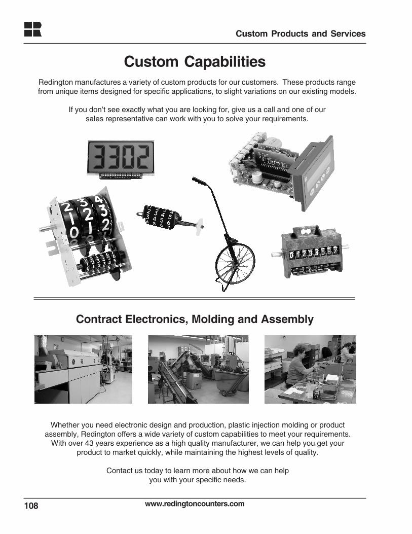
www.redingtoncounters.com108
Custom Products and Services
Contract Electronics, Molding and Assembly
Whether you need electronic design and production, plastic injection molding or productassembly, Redington offers a wide variety of custom capabilities to meet your requirements.
With over 43 years experience as a high quality manufacturer, we can help you get yourproduct to market quickly, while maintaining the highest levels of quality.
Contact us today to learn more about how we can helpyou with your specific needs.
Custom CapabilitiesRedington manufactures a variety of custom products for our customers. These products rangefrom unique items designed for specific applications, to slight variations on our existing models.
If you don’t see exactly what you are looking for, give us a call and one of oursales representative can work with you to solve your requirements.