Red Hat JBoss Fuse Service Works 6 · Red Hat JBoss Fuse Service Works is a platform for developing...
66
Red Hat JBoss Fuse Service Works 6.0 User Guide This guide is for Red Hat JBoss Fuse Service Works users and developers. Last Updated: 2017-11-12
Transcript of Red Hat JBoss Fuse Service Works 6 · Red Hat JBoss Fuse Service Works is a platform for developing...

Red Hat JBoss Fuse Service Works 6.0
User Guide
This guide is for Red Hat JBoss Fuse Service Works users and developers.
Last Updated: 2017-11-12


Red Hat JBoss Fuse Service Works 6.0 User Guide
This guide is for Red Hat JBoss Fuse Service Works users and developers.
Red Hat Content Services
Legal Notice
Copyright © 2015 Red Hat, Inc..
This document is licensed by Red Hat under the Creative Commons Attribution-ShareAlike 3.0Unported License. If you distribute this document, or a modified version of it, you must provideattribution to Red Hat, Inc. and provide a link to the original. If the document is modified, all RedHat trademarks must be removed.
Red Hat, as the licensor of this document, waives the right to enforce, and agrees not to assert,Section 4d of CC-BY-SA to the fullest extent permitted by applicable law.
Red Hat, Red Hat Enterprise Linux, the Shadowman logo, JBoss, OpenShift, Fedora, the Infinitylogo, and RHCE are trademarks of Red Hat, Inc., registered in the United States and othercountries.
Linux ® is the registered trademark of Linus Torvalds in the United States and other countries.
Java ® is a registered trademark of Oracle and/or its affiliates.
XFS ® is a trademark of Silicon Graphics International Corp. or its subsidiaries in the UnitedStates and/or other countries.
MySQL ® is a registered trademark of MySQL AB in the United States, the European Union andother countries.
Node.js ® is an official trademark of Joyent. Red Hat Software Collections is not formally relatedto or endorsed by the official Joyent Node.js open source or commercial project.
The OpenStack ® Word Mark and OpenStack logo are either registered trademarks/service marksor trademarks/service marks of the OpenStack Foundation, in the United States and othercountries and are used with the OpenStack Foundation's permission. We are not affiliated with,endorsed or sponsored by the OpenStack Foundation, or the OpenStack community.
All other trademarks are the property of their respective owners.
Abstract
This guide teaches users how to utilize the Red Hat JBoss Fuse Service Works' graphical tools andweb consoles.

. . . . . . . . . . . . . . . . . . . . . . . . . . . . . . . . . . . . . . . . . . . . . . . . . . . . . . . . . . . . . . . . . . . . . . . . . . . . . . . . . . . . . . . . . . . . . . . . . . . . . . . . . . . . . . . . . . . . . . . . . . . . . . . . . . . . . . . . . . . . . . . . . . . . . . . . . . . . . . . . . . . . . . . . . . . . . . . . . . . . . . . . . . . . . . . . . . . . . . . . . . . . . . . . . . . . . . . . . . . . . . . . . . . . . . . . . . . . . . . . . . . . . . . . . . . . . . . . . . . . . . . . . . . . . . . . . . . . . . . .
. . . . . . . . . . . . . . . . . . . . . . . . . . . . . . . . . . . . . . . . . . . . . . . . . . . . . . . . . . . . . . . . . . . . . . . . . . . . . . . . . . . . . . . . . . . . . . . . . . . . . . . . . . . . . . . . . . . . . . . . . . . . . . . . . . . . . . . . . . . . . . . . . . . . . . . . . . . . . . . . . . . . . . . . . . . . . . . . . . . . . . . . . . . . . . . . . . . . . . . . . . . . . . . . . . . . . . . . . . . . . . . . . . . . . . . . . . . . . . . . . . . . . . . . . . . . . . . . . . . . . . . . . . . . . . . . . . . . . . . .
. . . . . . . . . . . . . . . . . . . . . . . . . . . . . . . . . . . . . . . . . . . . . . . . . . . . . . . . . . . . . . . . . . . . . . . . . . . . . . . . . . . . . . . . . . . . . . . . . . . . . . . . . . . . . . . . . . . . . . . . . . . . . . . . . . . . . . . . . . . . . . . . . . . . . . . . . . . . . . . . . . . . . . . . . . . . . . . . . . . . . . . . . . . . . . . . . . . . . . . . . . . . . . . . . . . . . . . . . . . . . . . . . . . . . . . . . . . . . . . . . . . . . . . . . . . . . . . . . . . . . . . . . . . . . . . . . . . . . . . .
. . . . . . . . . . . . . . . . . . . . . . . . . . . . . . . . . . . . . . . . . . . . . . . . . . . . . . . . . . . . . . . . . . . . . . . . . . . . . . . . . . . . . . . . . . . . . . . . . . . . . . . . . . . . . . . . . . . . . . . . . . . . . . . . . . . . . . . . . . . . . . . . . . . . . . . . . . . . . . . . . . . . . . . . . . . . . . . . . . . . . . . . . . . . . . . . . . . . . . . . . . . . . . . . . . . . . . . . . . . . . . . . . . . . . . . . . . . . . . . . . . . . . . . . . . . . . . . . . . . . . . . . . . . . . . . . . . . . . . . .
. . . . . . . . . . . . . . . . . . . . . . . . . . . . . . . . . . . . . . . . . . . . . . . . . . . . . . . . . . . . . . . . . . . . . . . . . . . . . . . . . . . . . . . . . . . . . . . . . . . . . . . . . . . . . . . . . . . . . . . . . . . . . . . . . . . . . . . . . . . . . . . . . . . . . . . . . . . . . . . . . . . . . . . . . . . . . . . . . . . . . . . . . . . . . . . . . . . . . . . . . . . . . . . . . . . . . . . . . . . . . . . . . . . . . . . . . . . . . . . . . . . . . . . . . . . . . . . . . . . . . . . . . . . . . . . . . . . . . . . .
. . . . . . . . . . . . . . . . . . . . . . . . . . . . . . . . . . . . . . . . . . . . . . . . . . . . . . . . . . . . . . . . . . . . . . . . . . . . . . . . . . . . . . . . . . . . . . . . . . . . . . . . . . . . . . . . . . . . . . . . . . . . . . . . . . . . . . . . . . . . . . . . . . . . . . . . . . . . . . . . . . . . . . . . . . . . . . . . . . . . . . . . . . . . . . . . . . . . . . . . . . . . . . . . . . . . . . . . . . . . . . . . . . . . . . . . . . . . . . . . . . . . . . . . . . . . . . . . . . . . . . . . . . . . . . . . . . . . . . . .
Table of Contents
CHAPTER 1. RED HAT JBOSS FUSE SERVICE WORKS1.1. WHAT IS RED HAT JBOSS FUSE SERVICE WORKS?1.2. CORE FUNCTIONALITY1.3. SYSTEM INTEGRATION1.4. INTEGRATION USE CASE1.5. CORE AND COMPONENTS1.6. RED HAT JBOSS FUSE SERVICE WORKS FEATURES1.7. COMPONENTS OF RED HAT JBOSS FUSE SERVICE WORKS
CHAPTER 2. READ ME2.1. BACK UP YOUR DATA2.2. RED HAT DOCUMENTATION SITE
CHAPTER 3. JBOSS INTEGRATION AND SOA DEVELOPMENT3.1. JBOSS INTEGRATION AND SOA DEVELOPMENT3.2. INSTALLING JBOSS DEVELOPER STUDIO INTEGRATION STACK3.3. HELPFUL TIPS3.4. RUNNING QUICKSTARTS FROM JBOSS DEVELOPER STUDIO3.5. IMPORT PROJECTS FROM A GIT REPOSITORY IN JBOSS DEVELOPER STUDIO3.6. SETTING A NEW RULES RUNTIME IN JBOSS DEVELOPER STUDIO
CHAPTER 4. SETTING UP THE SERVER4.1. ADD JBOSS EAP SERVER
CHAPTER 5. RULES5.1. DSL5.2. DSL EDITOR5.3. DSL EDITOR COMPONENTS5.4. ADD A LANGUAGE MAPPING WIZARD5.5. EDIT THE LANGUAGE MAPPING WIZARD5.6. JBOSS RULES FLOW EDITOR5.7. DIFFERENT TYPES OF CONTROL ELEMENTS IN FLOW PALETTE5.8. DIFFERENT TYPES OF NODES IN FLOW PALETTE5.9. RULE EDITOR5.10. CONTENT ASSIST5.11. CODE FOLDING5.12. SYNCHRONIZATION WITH OUTLINE VIEW5.13. RETE TREE VIEW5.14. BREAKPOINTS5.15. CREATING BREAKPOINTS5.16. DEBUGGING
CHAPTER 6. JBOSS DEVELOPER STUDIO BPEL PROJECTS6.1. BPEL6.2. APACHE ODE6.3. LOGGING INTO BPEL6.4. CREATING A BPEL PROJECT6.5. CREATING A BPEL PROCESS6.6. CREATE A NEW SERVER RUNTIME6.7. EDITING A BPEL PROCESS FILE6.8. TABS SHOWN IN THE PROPERTIES VIEW6.9. OBSERVING A BPEL PROCESS6.10. ADDING A SERVICE TO A WSDL FILE
44455566
888
99911111213
1515
171717171919
2020212323232323232424
2626262626293233333434
Table of Contents
1
. . . . . . . . . . . . . . . . . . . . . . . . . . . . . . . . . . . . . . . . . . . . . . . . . . . . . . . . . . . . . . . . . . . . . . . . . . . . . . . . . . . . . . . . . . . . . . . . . . . . . . . . . . . . . . . . . . . . . . . . . . . . . . . . . . . . . . . . . . . . . . . . . . . . . . . . . . . . . . . . . . . . . . . . . . . . . . . . . . . . . . . . . . . . . . . . . . . . . . . . . . . . . . . . . . . . . . . . . . . . . . . . . . . . . . . . . . . . . . . . . . . . . . . . . . . . . . . . . . . . . . . . . . . . . . . . . . . . . . . .
. . . . . . . . . . . . . . . . . . . . . . . . . . . . . . . . . . . . . . . . . . . . . . . . . . . . . . . . . . . . . . . . . . . . . . . . . . . . . . . . . . . . . . . . . . . . . . . . . . . . . . . . . . . . . . . . . . . . . . . . . . . . . . . . . . . . . . . . . . . . . . . . . . . . . . . . . . . . . . . . . . . . . . . . . . . . . . . . . . . . . . . . . . . . . . . . . . . . . . . . . . . . . . . . . . . . . . . . . . . . . . . . . . . . . . . . . . . . . . . . . . . . . . . . . . . . . . . . . . . . . . . . . . . . . . . . . . . . . . . .
6.11. CREATING A DEPLOY.XML FILE6.12. CREATING JBOSS BPEL SERVER6.13. CREATING CORRELATION SETS6.14. EXAMPLE BPEL COMPONENT IMPLEMENTATION6.15. STRUCTURE OF A SWITCHYARD BPEL APPLICATION6.16. WIZARDS6.17. VIEWS6.18. PROPERTY SECTION TABS6.19. PROCESS PROPERTY SHEET TABS6.20. DETAILS TAB OPTIONS6.21. BPEL DESIGNER FEATURES6.22. BPEL DESIGNER CONCEPTS6.23. BPEL DEPLOYMENT DESCRIPTOR EDITOR PROPERTIES6.24. DIALOGS6.25. CHEAT SHEETS6.26. CONTEXT MENU
CHAPTER 7. JBOSS DEVELOPER STUDIO GUVNOR TASKS7.1. GUVNOR REPOSITORY EXPLORING PERSPECTIVE7.2. CREATING A NEW GUVNOR CONNECTION7.3. CONFIGURING THE GUVNOR CONNECTION WIZARD7.4. GETTING LOCAL COPIES OF GUVNOR FILES7.5. MANAGING GUVNOR RESOURCES7.6. RESOURCE FROM GUVNOR WIZARD7.7. GUVNOR REPOSITORIES VIEW7.8. GUVNOR RESOURCE HISTORY VIEW7.9. CONFIGURING THE GUVNOR RESOURCE HISTORY VIEW7.10. GUVNOR PREFERENCES7.11. GUVNOR REPOSITORY CONNECTION PREFERENCES7.12. LOCAL GUVNOR REPOSITORY RESOURCE DECORATION PREFERENCES
APPENDIX A. REVISION HISTORY
37394040414142434445484950515253
54545455565758596060606061
62
User Guide
2

Table of Contents
3
CHAPTER 1. RED HAT JBOSS FUSE SERVICE WORKS
1.1. WHAT IS RED HAT JBOSS FUSE SERVICE WORKS?
Red Hat JBoss Fuse Service Works is a platform for developing enterprise application integration (EAI)and service-oriented architecture (SOA) solutions. It consists of a service component framework,business rules/complex event processing, life-cycle governance, runtime governance, and processautomation. Red Hat JBoss Fuse Service Works is built on the same core as JBoss Fuse, and includesenterprise messaging, Apache Camel, and Apache CXF. Red Hat JBoss Fuse Service Works enablesusers to design, deploy, integrate, and orchestrate business services.
Red Hat JBoss Fuse Service Works can be used to integrate your major business systems into acohesive infrastructure. Development is simplified with a transparent, lightweight service frameworkwhich uses Enterprise Integration Platform (EIP) technology. This allows developers to work withfamiliar technologies such as Apache Camel, BPEL, BPMN, or POJOs. To reduce the operational costsof production and maintenance, the platform utilizes an automatable, content-aware repository andservice activity monitoring. These support the entire service life cycle.
Report a bug
1.2. CORE FUNCTIONALITY
Red Hat JBoss Fuse Service Works provides the following core functionality:
Enterprise Integration Pattern (EIP) Based Development
The versatile EIP framework is implemented in routing and transformation processes for faster andmore efficient integration solutions.
High Performance Messaging
A high performance messaging broker supports messaging patterns such as publish-subscribe,point-to-point, and store-forward, and multiple cross language clients.
Service Development
The web services framework exposes integration assets as services and calls external services,supporting all major web services standards. It also supports RESTful calls.
Structured Service Development
A lightweight service development framework provides full life-cycle support for developing,deploying, and managing service-based applications.
Automatable Registry with Workflow
Manage the life-cycle of services from design, development, and deployment by defining, exposing,and enforcing rules or policies.
Business Transaction Monitoring
Capture service activity information, define and collect metrics, and define alerts and SLAs.
Report a bug
User Guide
4

1.3. SYSTEM INTEGRATION
Integrating your major business systems into a cohesive infrastructure can be a challenge, especiallywhen you have legacy applications. Red Hat JBoss Fuse Service Works provides a number of ways thatenable you to integrate both new and legacy applications. Development is simplified with atransparent, lightweight service framework which uses the EIP technology. This allows developers tofocus on higher order concepts while still working with familiar technologies such as Apache Camel,BPEL, BPMN, or POJOs. To reduce the operational costs of production and maintenance, the platformutilizes an automatable, content-aware repository and service activity monitoring. These support theentire service life cycle and development, QA, and production teams with runtime and design timevisibility, monitoring, and alerting.
Report a bug
1.4. INTEGRATION USE CASE
Acme Equity is a large financial service. The company possesses many databases and systems. Someare older, COBOL-based legacy systems and some are databases obtained through the acquisition ofsmaller companies in recent years. It is challenging and expensive to integrate these databases asbusiness rules frequently change. The company wants to develop a new series of client-facing e-commerce websites, but these may not synchronize well with the existing systems as they currentlystand.
The company wants an inexpensive solution but one that adheres to the strict regulations and securityrequirements of the financial sector. What the company does not want to do is to have to write andmaintain “glue code” to connect their legacy databases and systems.
Red Hat JBoss Fuse Service Works was selected as a middleware layer to integrate these legacysystems with the new customer websites. It provides a bridge between front-end and back-endsystems. Business rules implemented with Red Hat JBoss Fuse Service Works can be updated quicklyand easily.
As a result, older systems can now synchronize with newer ones due to the unifying methods of RedHat JBoss Fuse Service Works. There are no bottlenecks, even with tens of thousands of transactionsper month. Various integration types, such as XML, JMS and FTP, are used to move data betweensystems. Any one of a number of enterprise-standard messaging systems can be plugged into Red HatJBoss Fuse Service Works providing further flexibility.
An additional benefit is that the system can now be scaled upwards easily as more servers anddatabases are added to the existing infrastructure.
Report a bug
1.5. CORE AND COMPONENTS
Red Hat JBoss Fuse Service Works provides an environment for easily applying SOA concepts tointegrated applications. A SwitchYard application consists of components such as composite servicesand composite references. These provide service definitions and accessibility.
Along with SwitchYard, Red Hat JBoss Fuse Service Works is made up of a number of componentsincluding a rules-based router (Apache Camel), a web service framework (Apache CXF), and a messagebroker (Apache ActiveMQ).
Report a bug
CHAPTER 1. RED HAT JBOSS FUSE SERVICE WORKS
5

1.6. RED HAT JBOSS FUSE SERVICE WORKS FEATURES
SwitchYard
SwitchYard is a lightweight service delivery framework providing full life-cycle support fordeveloping, deploying, and managing service-oriented applications.
Business Process Execution Language (BPEL)
You can use web services to orchestrate business rules using this language. It is included with RedHat JBoss Fuse Service Works for the execution of business process instructions.
Smooks
This transformation engine can be used in conjunction with Red Hat JBoss Fuse Service Works toprocess messages. It can also be used to split messages and send them to the correct destination.
JBoss Rules
This is the rules engine that is packaged with Red Hat JBoss Fuse Service Works. It can infer datafrom the messages it receives to determine which actions need to be performed.
Report a bug
1.7. COMPONENTS OF RED HAT JBOSS FUSE SERVICE WORKS
Red Hat JBoss Fuse Service Works ships with a number of components which enable its multi-functional capabilities.
Table 1.1. Red Hat JBoss Fuse Service Works Components
Component Function
SwitchYard Service delivery framework
JBoss Rules Business rules engine with complex event processing
Design Time Governance A service registry/repository
Runtime Governance Service activity monitoring
JBoss Operations Network Operations, administration, and management tools
JBoss EAP A full JavaEE application server
Apache Camel Rules Based Router
Smooks Framework for processing XML and non-XML data using Java
ModeShape Data Store
ActiveMQ/A-MQ Messaging Messaging and Integration Patterns Server
User Guide
6
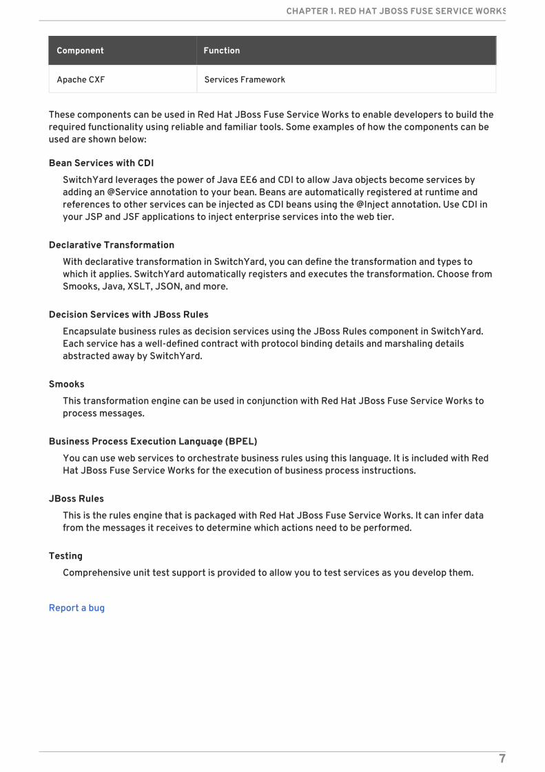
Apache CXF Services Framework
Component Function
These components can be used in Red Hat JBoss Fuse Service Works to enable developers to build therequired functionality using reliable and familiar tools. Some examples of how the components can beused are shown below:
Bean Services with CDI
SwitchYard leverages the power of Java EE6 and CDI to allow Java objects become services byadding an @Service annotation to your bean. Beans are automatically registered at runtime andreferences to other services can be injected as CDI beans using the @Inject annotation. Use CDI inyour JSP and JSF applications to inject enterprise services into the web tier.
Declarative Transformation
With declarative transformation in SwitchYard, you can define the transformation and types towhich it applies. SwitchYard automatically registers and executes the transformation. Choose fromSmooks, Java, XSLT, JSON, and more.
Decision Services with JBoss Rules
Encapsulate business rules as decision services using the JBoss Rules component in SwitchYard.Each service has a well-defined contract with protocol binding details and marshaling detailsabstracted away by SwitchYard.
Smooks
This transformation engine can be used in conjunction with Red Hat JBoss Fuse Service Works toprocess messages.
Business Process Execution Language (BPEL)
You can use web services to orchestrate business rules using this language. It is included with RedHat JBoss Fuse Service Works for the execution of business process instructions.
JBoss Rules
This is the rules engine that is packaged with Red Hat JBoss Fuse Service Works. It can infer datafrom the messages it receives to determine which actions need to be performed.
Testing
Comprehensive unit test support is provided to allow you to test services as you develop them.
Report a bug
CHAPTER 1. RED HAT JBOSS FUSE SERVICE WORKS
7

CHAPTER 2. READ ME
2.1. BACK UP YOUR DATA
WARNING
Red Hat recommends that you back up your system settings and data beforeundertaking any of the configuration tasks mentioned in this book.
Report a bug
2.2. RED HAT DOCUMENTATION SITE
Red Hat's official documentation site is at https://access.redhat.com/site/documentation/. There youwill find the latest version of every book, including this one.
Report a bug
User Guide
8
CHAPTER 3. JBOSS INTEGRATION AND SOA DEVELOPMENT
3.1. JBOSS INTEGRATION AND SOA DEVELOPMENT
The JBoss Integration and SOA Development plug-in is provided to support JBoss Fuse ServiceWorks in JBoss Developer Studio. It provides the following features:
Creation of SwitchYard projects
Adding SwitchYard capabilities to existing Maven based JBoss Developer Studio projects
Configuration of SwitchYard capabilities
A graphical editor for editing SwitchYard application configuration
Java2WSDL
XML catalog entries for SwitchYard configuration schema
Integration supporting the SwitchYard Maven plug-in (org.switchyard:switchyard-plugin)
Support for workspace deployment of SwitchYard projects
The JBoss Integration and SOA Development plug-in is provided by the JBoss Development StudioIntegration Stack.
Report a bug
3.2. INSTALLING JBOSS DEVELOPER STUDIO INTEGRATION STACK
JBoss Developer Studio Integration Stack is not packaged as part of JBoss Developer Studioinstallations. These plug-ins must be installed independently through JBoss Central, as detailed in theprocedure below.
Procedure 3.1. Install JBoss Developer Studio Integration Stack
1. Start JBoss Developer Studio.
2. In JBoss Central, select the Software/Update tab. Scroll through the list to locate JBoss Developer Studio Integration Stack. Select the check box next to JBoss Integration and SOA Development and click Install.
CHAPTER 3. JBOSS INTEGRATION AND SOA DEVELOPMENT
9

Figure 3.1. Find JBoss Developer Studio Integration Stack in JBoss CentralSoftware/Update Tab
3. In the Install wizard, ensure the check boxes are selected for the software you want to installand click Next. It is recommended that you install all of the selected components.
4. Review the details of the items listed for install and click Next. After reading and agreeing tothe license(s), click I accept the terms of the license agreement(s) and click Finish. The Installing Software window opens and reports the progress of theinstallation.
5. During the installation process you may receive warnings about installing unsigned content. Ifthis is the case, check the details of the content and if satisfied click OK to continue with theinstallation.
Figure 3.2. Warning Prompt for Installing Unsigned Content
6. Once installing is complete, you are prompted to restart the IDE. Click Yes to restart now and No if you need to save any unsaved changes to open projects. Note that changes do not takeeffect until the IDE is restarted.
User Guide
10
Once installed, you may need to complete additional configuration actions before you can use theindividual JBoss Developer Studio Integration Stack components. For plug-in specific configurationinformation, see the appropriate Red Hat JBoss product documentation available fromhttps://access.redhat.com/site/documentation on the Red Hat Customer Portal.
IMPORTANT
The installation method for early releases of JBoss Developer Studio Integration Stackmay vary from that given here. For instructions, see the appropriate Red Hat JBossproduct documentation available from https://access.redhat.com/site/documentationon the Red Hat Customer Portal.
Report a bug
3.3. HELPFUL TIPS
Honor all XML schema locations
After installation, go to XML → XML Files → Validation → Preferences and ensure Honor all XML schema locations check box is cleared. This prevents erroneous XML validation errorsfrom appearing on switchyard.xml files.
DTD warning
Importing SwitchYard quickstarts into JBoss Developer Studio results in non-fatal warningsregarding log4j.dtd. These can be safely ignored. To stop receiving the warning, ensure the file log4j.xml is closed before starting a project.
JavaSE-1.6 error message
When commencing a project, a warning may be displayed saying "Build path specifies executionenvironment JavaSE-1.6". To disable this warning, go to your Java preferences and ensure thatJavaSE-1.7 JDK is checked to support JavaSE-1.6 environments.
Report a bug
3.4. RUNNING QUICKSTARTS FROM JBOSS DEVELOPER STUDIO
Overview
This topic demonstrates how to import a quickstart application to JBoss Developer Studio and thendeploy it to a running application server.
Prerequisites
The JBoss Integration and SOA Development tools must be installed from the JBoss Developer StudioIntegration Stack.
1. Open JBoss Developer Studio.
2. Click File → Import → Maven → Existing Maven Projects.
3. Select Browse and navigate to the quickstart directory, for example, EAP_HOME/quickstarts/switchyard/bean-service and then select OK.
CHAPTER 3. JBOSS INTEGRATION AND SOA DEVELOPMENT
11
The import tool scans the directory to locate the associated pom.xml file.
4. Click Finish.
5. The quickstart is listed in the Project Explorer view. You can expand the project to explore itscontents.
6. In the Project Explorer view, right-click on the project's name and click Run as → Run onserver → EAP.
Result
The quickstart application is deployed to the server and enabled by default.
Report a bug
3.5. IMPORT PROJECTS FROM A GIT REPOSITORY IN JBOSSDEVELOPER STUDIO
JBoss Developer Studio can be configured to connect to a central Git asset repository. The repositoryis where versions of rules, models, functions and processes are stored. This Git repository must alreadybe defined by the KIE Workbench.
1. Start the Red Hat JBoss server (if not already running) by selecting the server from the servertab and click the start icon.
2. Select File → Import and navigate to the Git folder. Open the Git folder to select Projects fromGit and click next.
3. Select the repository source as URI and click next.
4. Enter the details of the Git repository in the next window and click next.
User Guide
12

Figure 3.3. Git Repository Details
5. Select which branch you want to import in the next window and click next.
6. You are presented with the option to define the local storage for this project. Enter (or select)a non-empty directory, make any configuration changes and click next.
7. Import the project as a general project in the next window and click next. Name this projectand click Finish.
Report a bug
3.6. SETTING A NEW RULES RUNTIME IN JBOSS DEVELOPER STUDIO
Setting this runtime provides an environment for new rules sets. It consists of a collection of jar fileswhich are then utilized in rules creation. Once you have set up a runtime, you can go about adding andmodifying rules in JBoss Developer Studio.
1. Download and unzip the runtime jars files located in the jboss-brms-engine.zip archive ofthe JBoss BRMS Deployable zip archive (available from Red Hat Customer Portal ).
CHAPTER 3. JBOSS INTEGRATION AND SOA DEVELOPMENT
13

2. From the Red Hat JBoss Developer Studio menu, select Window and click Preferences.
3. Select JBoss Rules → Installed JBoss Rules Runtimes → Runtime locations.
4. Click Add; provide a name for the new runtime, and click Browse to navigate to the directorywhere the runtime is located.
5. Click OK, select the new runtime and click OK again. A dialog box indicates, if you have existingprojects, that JBoss Developer Studio must be restarted to update the Runtime.
Report a bug
User Guide
14

CHAPTER 4. SETTING UP THE SERVERTo make it possible for the tooling to manage a server, you need to add it to the Servers list. You canset up target runtime server using the Servers view. Once added, the server is displayed in theServers view. Selecting a server in Servers view, enables you to start it, to stop it, or to delete itsconfiguration. You can add multiple servers of the same type, as long as each uses a separateinstallation directory.
Report a bug
4.1. ADD JBOSS EAP SERVER
1. In JBoss Developer Studio, click the Servers view. If the Servers view is not visible, clickWindow → Show View → Servers.
2. If no servers have been previously created then the Servers view displays a new serverhyperlink. Click this link to create a new server.
If there are one or more existing servers, right-click an existing server and click New →Server.
3. In the Define a New Server dialog, select a JBoss Enterprise Application Platform serverfrom the Select the server type list.
4. The Server's host name and Server name fields are completed by default. In the Server name field, you can type a custom name by which to identify the server in the Serversview.
5. From the Server runtime environment list, select an existing server runtimeenvironment for the application server type. Alternatively, to create a new runtimeenvironment click Add and complete the fields and options as appropriate.
NOTE
If the Server runtime environment field is not shown, no server runtimeenvironments exist for the selected application server type. To create a newserver runtime environment without canceling the wizard, click Next andcomplete the fields and options as appropriate.
6. Click Next.
7. The server behavior options displayed vary depending on the selected application server type.To specify that the server life-cycle is to be managed from outside the IDE, select the Server is externally managed check box.
To specify that the server should be launched to respond to requests on all hostnames, selectthe Listen on all interfaces to allow remote web connections check box.
From the location list, select Local. Click Next.
CHAPTER 4. SETTING UP THE SERVER
15
NOTE
The Expose your management port as the server's hostname option, whichenables management commands sent by the IDE to be successfully received bythe server, is bypassed for local servers regardless of whether the check box isselected.
8. To select applications to deploy with this server, from the Available list select the applicationsand click Add. Applications to be deployed are detailed in the Configured list.
9. Click Finish to create the server.
Result
The new server appears in the list of servers in the Servers panel.
IMPORTANT
You can create multiple servers that use the same application server. But a warning isdisplayed if you try to simultaneously run more than one server on the same host. This isbecause multiple running servers on the same host can result in port conflicts.
Report a bug
User Guide
16

CHAPTER 5. RULES
5.1. DSL
A domain-specific language (DSL) is a set of custom rules, that is created specifically to solveproblems in a particular domain and is not intended to be able to solve problems outside it. A DSL'sconfiguration is stored in plain text.
Report a bug
5.2. DSL EDITOR
In JBoss Rules, the DSL configuration is stored in .dsl files. These can be created selectingFile → New → Other → Drools → Domain Specific Language from the projects context menu.
Figure 5.1. The DSL editor
Report a bug
5.3. DSL EDITOR COMPONENTS
Table 5.1. DSL Editor Components
Components Description
Description User's comments on a certain language messagemapping.
CHAPTER 5. RULES
17

Table of language message mappings The table is divided into 4 rows:
Language Expression : expression you wantto use as a rule
Rule Language Mapping : the implementationof the rules. The rule for this languageexpression is compiled by the rule enginecompiler.
Object : name of the object
Scope : indicates where the expression istargeted, if its for the "condition" part of therule ,"consequence" part, etc.
By clicking on some row's header you can sort thelines in the table according to the clicked row. Bydouble clicking on the line the Edit languagemapping is displayed.
Expression Shows the language expression of the selected tableline (language message mapping).
Mapping Shows the rule of language mapping for the selectedtable line (language message mapping).
Object Shows the object for the selected table line(language message mapping).
Sort By This option allows you to change the sorting order ofthe language message mappings. To do this selectfrom the drop down list the method of sorting youwant and click the Sort button.
ButtonsEdit : Click this button to edit the selectedline in the language message mappingstable.
Remove : Click this button to delete theselected mapping line.
Add : Click this button to add new mappinglines to the table.
Sort : See the Sort By row above for moreinformation.
Copy : Click this button to add new mappinglines to the table in which all theinformation is copied from the selectedmapping line.
Components Description
User Guide
18
Report a bug
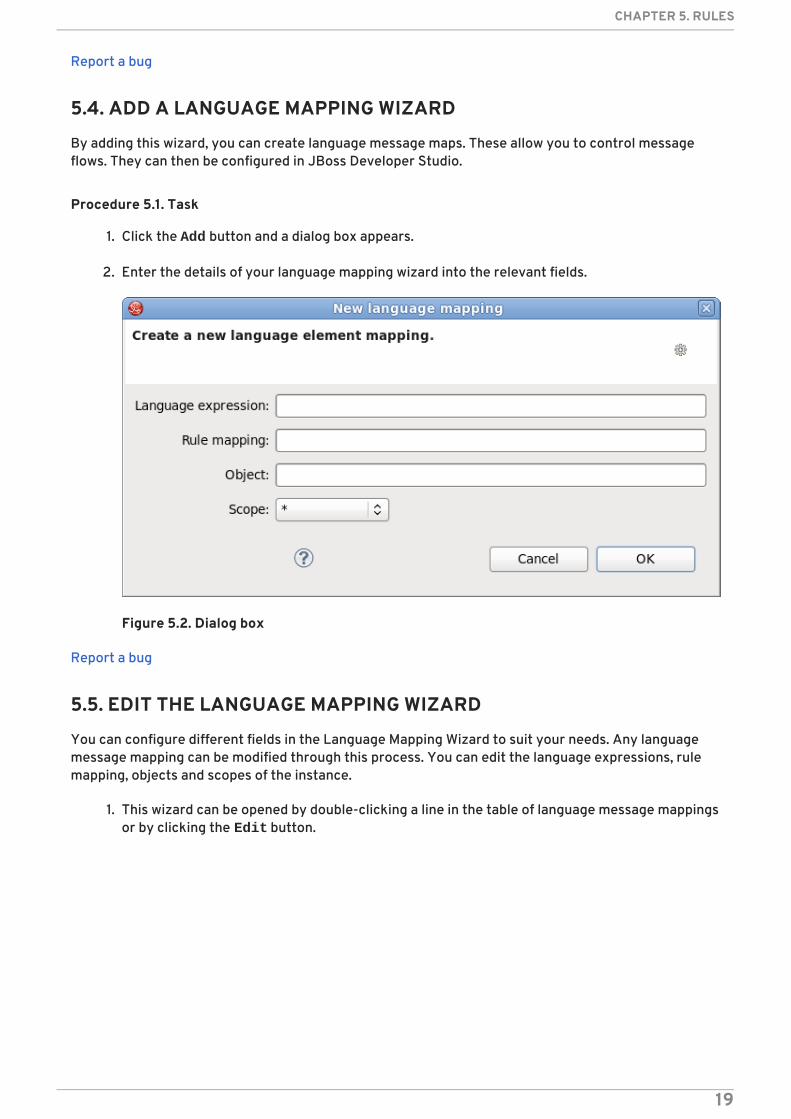
5.4. ADD A LANGUAGE MAPPING WIZARD
By adding this wizard, you can create language message maps. These allow you to control messageflows. They can then be configured in JBoss Developer Studio.
Procedure 5.1. Task
1. Click the Add button and a dialog box appears.
2. Enter the details of your language mapping wizard into the relevant fields.
Figure 5.2. Dialog box
Report a bug
5.5. EDIT THE LANGUAGE MAPPING WIZARD
You can configure different fields in the Language Mapping Wizard to suit your needs. Any languagemessage mapping can be modified through this process. You can edit the language expressions, rulemapping, objects and scopes of the instance.
1. This wizard can be opened by double-clicking a line in the table of language message mappingsor by clicking the Edit button.
CHAPTER 5. RULES
19
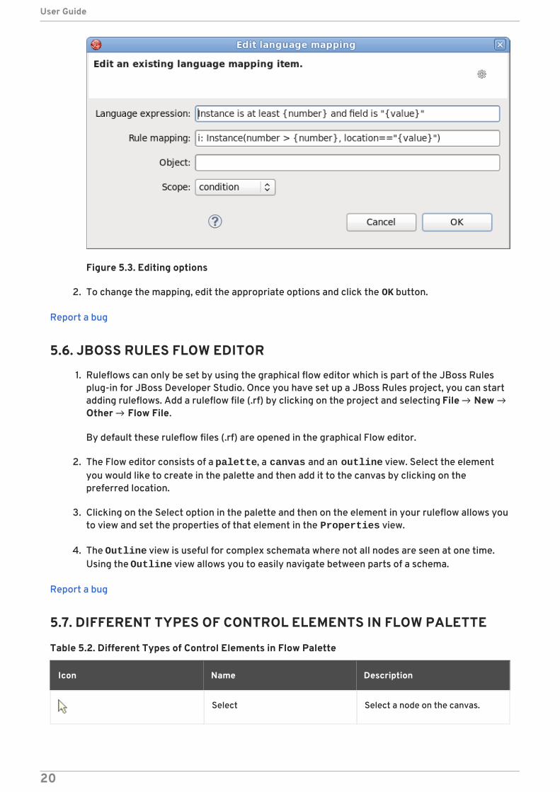
Figure 5.3. Editing options
2. To change the mapping, edit the appropriate options and click the OK button.
Report a bug
5.6. JBOSS RULES FLOW EDITOR
1. Ruleflows can only be set by using the graphical flow editor which is part of the JBoss Rulesplug-in for JBoss Developer Studio. Once you have set up a JBoss Rules project, you can startadding ruleflows. Add a ruleflow file (.rf) by clicking on the project and selecting File → New →Other → Flow File.
By default these ruleflow files (.rf) are opened in the graphical Flow editor.
2. The Flow editor consists of a palette, a canvas and an outline view. Select the elementyou would like to create in the palette and then add it to the canvas by clicking on thepreferred location.
3. Clicking on the Select option in the palette and then on the element in your ruleflow allows youto view and set the properties of that element in the Properties view.
4. The Outline view is useful for complex schemata where not all nodes are seen at one time.Using the Outline view allows you to easily navigate between parts of a schema.
Report a bug
5.7. DIFFERENT TYPES OF CONTROL ELEMENTS IN FLOW PALETTE
Table 5.2. Different Types of Control Elements in Flow Palette
Icon Name Description
Select Select a node on the canvas.
User Guide
20

Marquee Selects a group of elements.
Sequence flow Joins two elements on the canvas
Icon Name Description
Report a bug
5.8. DIFFERENT TYPES OF NODES IN FLOW PALETTE
Table 5.3. Different Types of Nodes in Flow Palette
Icon Name Description
Start Event The start of the ruleflow. Therecan only have one start node. TheStart Event cannot haveincoming connections and shouldhave one outgoing connection.Whenever the ruleflow process isstarted, the execution is startedhere and is automaticallyforwarded to the first node linkedto this Start Event.
End Event A ruleflow file can have multipleEnd Events. This node shouldhave one incoming connectionand no outgoing connections.When an end node is reached inthe ruleflow, the ruleflow isterminated (including otherremaining active nodes whenparallelism is used).
Rule Task Represents a set of rules. A RuleTask node should have oneincoming connection and oneoutgoing connection. TheRuleFlowGroup property is usedto specify the name of theruleflow-group representing theset of rules. When a Rule Tasknode is reached in the ruleflow,the engine starts executing rulesthat are part of thecorresponding ruleflow-group.Execution automaticallycontinues to the next node whenthere are no more active rules inthis ruleflow-group.
CHAPTER 5. RULES
21

Gateway[diverge] Allows you to create branches inyour ruleflow. AGateway[diverge] node shouldhave one incoming connectionand two or more outgoingconnections.
Gateway[converge] Allows you to synchronizemultiple branches. AGateway[converge] node shouldhave two or more incomingconnections and one outgoingconnection.
Reusable Sub-Process Represents the invocation ofanother ruleflow from thisruleflow. A subflow node shouldhave one incoming connectionand one outgoing connection. Itcontains the property processIdwhich specifies the ID of theprocess that should be executed.When a Reusable Sub-Processnode is reached in the ruleflow,the engine starts the processwith the given ID. The subflownode continues only if the othersubflow process has terminatedits execution. The subflowprocess is started as anindependent process, whichmeans that the subflow processis not terminated if this processreaches an end node.
Script Task Represents an action that shouldbe executed in this ruleflow. AScript Task node should have oneincoming connection and oneoutgoing connection. It containsthe property "action" whichspecifies the action that shouldbe executed. When a Script Tasknode is reached in the ruleflow, itexecutes the action and continuewith the next node. An actionshould be specified as a piece of(valid) MVEL code.
Icon Name Description
Report a bug
User Guide
22
5.9. RULE EDITOR
The Rule editor works on files that have a .drl (or .rule in the case of spreading rules acrossmultiple rule files) extension. The editor follows the pattern of a normal text editor in JBoss DeveloperStudio, with all the normal features of a text editor.
Report a bug
5.10. CONTENT ASSIST
While working in the Rule editor you can get a content assistance the usual way by pressing Ctrl+Space. Content Assist shows all possible keywords for the current cursor position. It alsosuggests all available fields in a message.
Report a bug
5.11. CODE FOLDING
Code Folding is used in the rule editor. It allows you to hide and show sections of a file use the iconswith minus and plus on the left vertical line of the editor.
Report a bug
5.12. SYNCHRONIZATION WITH OUTLINE VIEW
The Rule editor works in synchronization with the Outline view which shows the structure of rules,imports objects into the file and also performs file functions. The view is updated on save. It provides aquick way of navigating around rules by names in a file which may have hundreds of rules. The itemsare sorted alphabetically by default.
Report a bug
5.13. RETE TREE VIEW
The Rete Tree view shows you the current Rete Network for your .drl file. Just click on the Rete Treetab at the bottom of the Rule editor. Afterwards you can generate the current Rete Networkvisualization. You can push and pull the nodes to arrange your optimal network overview.
If you have a large number of nodes, you can select some of them with a frame and pull them together.You can zoom in and out the Rete tree in case not all nodes are shown in the current view. For this usethe combobox or + and - icons on the toolbar.
NOTE
The Rete Tree view works only in JBoss Rules Rule Projects, where the JBoss RulesBuilder is set in the project properties.
Report a bug
5.14. BREAKPOINTS
Whenever the execution of rules runs into a breakpoint, the execution is halted. Once the execution
CHAPTER 5. RULES
23

stops, you can inspect the variables known at that point and use any of the default debugging actionsto decide what should happen next (step over, continue, etc). The Debug view can be used to inspectthe content of the working memory and agenda.
Report a bug
5.15. CREATING BREAKPOINTS
Create breakpoints to help monitor rules that have been executed. Instead of waiting for the result toappear at the end of the process, you can inspect the details of the execution at each breakpoint youset. This is useful for debugging and ensuring rules are executed as expected.
1. To create breakpoints in the Package Explorer view or Navigator view of the JBoss Rulesperspective, double-click the selected .drl file to open it in the editor.
2. You can add and remove rule breakpoints in the .drl files in two ways:
Double-click the rule in the Rule editor at the line where you want to add a breakpoint.A breakpoint can be removed by double-clicking the rule once more.
NOTE
Rule breakpoints can only be created in the consequence of a rule. Double-clicking on a line where no breakpoint is allowed does nothing.
Right-click the ruler. Select the Toggle Breakpoint action in the context menu. Choosingthis action adds a breakpoint at the selected line or remove it if there is one already.
3. The Debug perspective contains a Breakpoints view which can be used to see alldefined breakpoints, get their properties, enable/disable and remove them. You can switch toit by clicking Window → Perspective → Others → Debug .
Report a bug
5.16. DEBUGGING
Once you have created breakpoints, you can use them to start debugging your rules processes whenrequired. This allows you to monitor errors and fixes them automatically where possible. By using thedebugging configuration with breakpoints, you can make sure your rules process runs as expected.
1. JBoss Rules breakpoints are only enabled if you debug your application as a JBoss RulesApplication. To do this you should perform one of two actions:
Select the main class of your application. Right-click on it and select Debug As → JBossRules Application .
Alternatively, select Debug As → Debug Configuration to open a new dialog window forcreating, managing and running debug configurations.
Select the JBoss Rules Application item in the left tree and click the New launch configuration button (leftmost icon in the toolbar above the tree). This creates a newconfiguration with a number of the properties already filled in based on main class youselected in the beginning. All properties shown here are the same as any standard Javaprogram.
User Guide
24

NOTE
Remember to change the name of your debug configuration to somethingmeaningful.
2. Click the Debug button on the bottom to start debugging your application.
3. After enabling the debugging, the application starts executing and halts if any breakpoint isencountered. This can be a JBoss Rules rule breakpoint, or any other standard Javabreakpoint. Whenever a JBoss Rules rule breakpoint is encountered, the corresponding .drlfile is opened and the active line is highlighted. The Variables view also contains all ruleparameters and their value. You can then use the default Java debug actions to decide what todo next (resume, terminate, step over, etc). The debug views can also be used to determine thecontents of the working memory and agenda at that time as well (the current executingworking memory is automatically shown).
Report a bug
CHAPTER 5. RULES
25
CHAPTER 6. JBOSS DEVELOPER STUDIO BPEL PROJECTS
6.1. BPEL
Business Process Execution Language (BPEL) is an OASIS-standard language for business rulesorchestration. The BPEL component in SwitchYard is a pluggable container in that allows a WS-BPELbusiness process to be exposed as a service through an interface defined using WSDL.
Report a bug
6.2. APACHE ODE
Apache ODE ("Orchestration Director Engine") is a software component that is designed to executeBPEL business processes. It sends and receives messages to and from web services, manipulates dataand performs error handling in the method prescribed in your process definition. To learn more aboutApache ODE, visit the project website at http://ode.apache.org/.
Report a bug
6.3. LOGGING INTO BPEL
You can access the BPEL server through your browser. Once you have logged in, you can begincreating and modifying projects in the graphical user interface. You are also able to change your logindetails to something more secure than the default.
Procedure 6.1. Task
1. Access the BPEL console at the following URL: http://localhost:8080/bpel-console. A loginscreen appears.
2. Enter your credentials. The default username is admin with password admin.
3. To change your login details, access the Settings tab in the BPEL editor and click on Users.In this section there are fields to change your username and password.
Report a bug
6.4. CREATING A BPEL PROJECT
Create a BPEL project to orchestrate your business rules. These projects negate the need to configureeach rule individually. You can create your BPEL project directly in the SwitchYard editor so you donot have to edit XML by hand. Once you have completed creating your project, you can applyadditional configurations to customize your business rules.
1. First, select File → New → Project → BPEL 2.0 → BPEL Project or Legacy BPEL Project fromthe menu bar. Then click the Next button.
User Guide
26
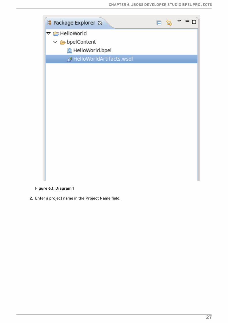
Figure 6.1. Diagram 1
2. Enter a project name in the Project Name field.
CHAPTER 6. JBOSS DEVELOPER STUDIO BPEL PROJECTS
27
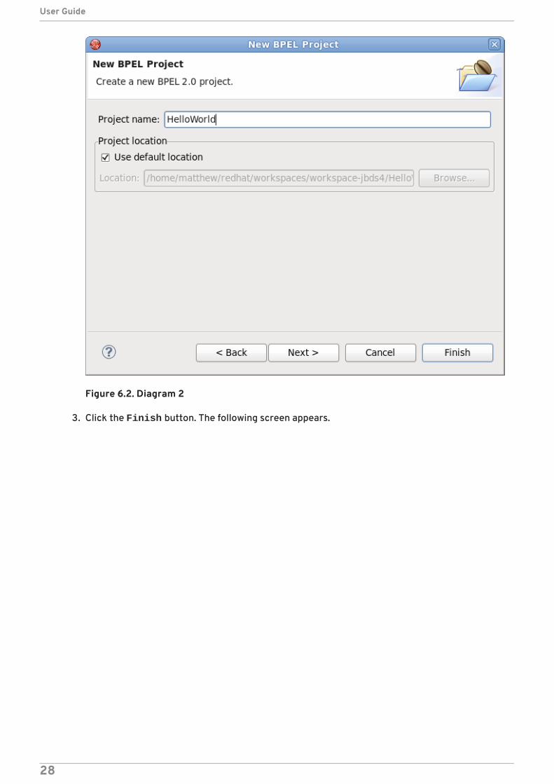
Figure 6.2. Diagram 2
3. Click the Finish button. The following screen appears.
User Guide
28

Figure 6.3. Diagram 3
4. You have now created a new project.
Report a bug
6.5. CREATING A BPEL PROCESS
Create a BPEL process to implement your projects. The wizard provides a simple way of setting theprocess defaults to provide maximum efficiency. Use it to customize values and WSDL information.
1. First, select File → New → Others → BPEL 2.0 → BPEL Process File and click Next.
CHAPTER 6. JBOSS DEVELOPER STUDIO BPEL PROJECTS
29

Figure 6.4. Diagram 1
2. From here you can choose to create a BPEL process from a template or a service description.The former is recommended.
3. Enter the following information:
Table 6.1. Fields and Values
Field Value
BPEL Process Name Enter a process name. For example, HelloWorld.
Namespace Enter or select a namespace for the BPEL process.
Template Select the appropriate template for the BPEL process. When youselect the template, you can see information about it. Select Synchronous BPEL Process.
User Guide
30

Figure 6.5. Diagram 2
4. Click Next. On this page, you can customize your WSDL service details using a template. Enterthe following information:
Table 6.2. Fields and Values
Field Value
Service Name A WSDL service name for the BPEL process. The default name is HelloWorld.
Port Name A WSDL port name for the BPEL process. The default name is HelloWorldPort.
Service Address An address of the WSDL service for the BPEL process. The defaultvalue is http://localhost:8080/HelloWorld.
Binding Protocol The binding protocol that you use in the WSDL. You can chooseSOAP or HTTP. The default value is SOAP.
CHAPTER 6. JBOSS DEVELOPER STUDIO BPEL PROJECTS
31
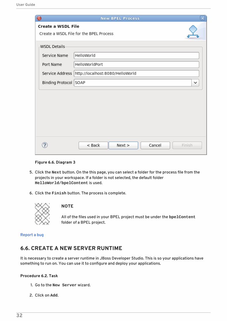
Figure 6.6. Diagram 3
5. Click the Next button. On the this page, you can select a folder for the process file from theprojects in your workspace. If a folder is not selected, the default folder HelloWorld/bpelContent is used.
6. Click the Finish button. The process is complete.
NOTE
All of the files used in your BPEL project must be under the bpelContentfolder of a BPEL project.
Report a bug
6.6. CREATE A NEW SERVER RUNTIME
It is necessary to create a server runtime in JBoss Developer Studio. This is so your applications havesomething to run on. You can use it to configure and deploy your applications.
Procedure 6.2. Task
1. Go to the New Server wizard.
2. Click on Add.
User Guide
32
3. Fill in the name if you wish to do so (this step is optional because the name is preset.
4. Click on Browse and select the home directory.
5. Select one of the available configurations (the configuration you choose must have the BPELengine available).
6. Click on Finish.
Report a bug
6.7. EDITING A BPEL PROCESS FILE
You can view a BPEL process file in the graphical interface. This way you are able to see all your BPELfiles in front of you and modify them accordingly. By selecting the file from the palette, you are able toedit it.
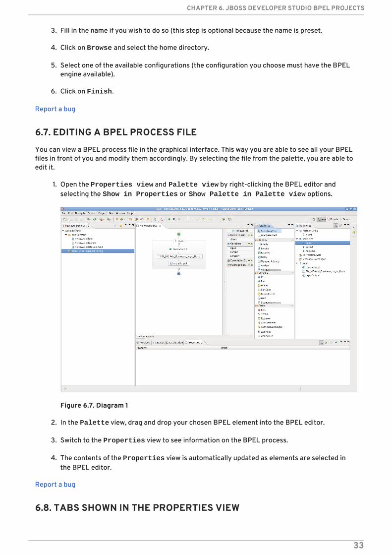
1. Open the Properties view and Palette view by right-clicking the BPEL editor andselecting the Show in Properties or Show Palette in Palette view options.
Figure 6.7. Diagram 1
2. In the Palette view, drag and drop your chosen BPEL element into the BPEL editor.
3. Switch to the Properties view to see information on the BPEL process.
4. The contents of the Properties view is automatically updated as elements are selected inthe BPEL editor.
Report a bug
6.8. TABS SHOWN IN THE PROPERTIES VIEW
CHAPTER 6. JBOSS DEVELOPER STUDIO BPEL PROJECTS
33
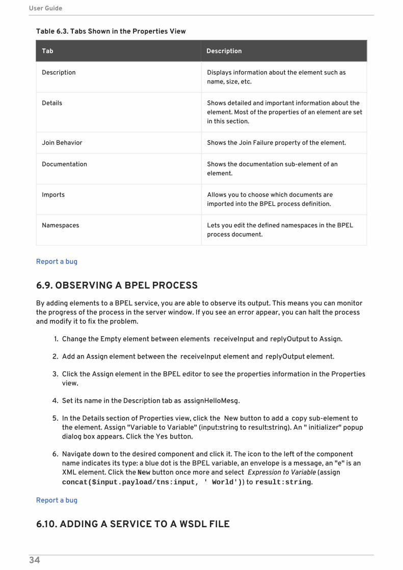
Table 6.3. Tabs Shown in the Properties View
Tab Description
Description Displays information about the element such asname, size, etc.
Details Shows detailed and important information about theelement. Most of the properties of an element are setin this section.
Join Behavior Shows the Join Failure property of the element.
Documentation Shows the documentation sub-element of anelement.
Imports Allows you to choose which documents areimported into the BPEL process definition.
Namespaces Lets you edit the defined namespaces in the BPELprocess document.
Report a bug
6.9. OBSERVING A BPEL PROCESS
By adding elements to a BPEL service, you are able to observe its output. This means you can monitorthe progress of the process in the server window. If you see an error appear, you can halt the processand modify it to fix the problem.
1. Change the Empty element between elements receiveInput and replyOutput to Assign.
2. Add an Assign element between the receiveInput element and replyOutput element.
3. Click the Assign element in the BPEL editor to see the properties information in the Propertiesview.
4. Set its name in the Description tab as assignHelloMesg.
5. In the Details section of Properties view, click the New button to add a copy sub-element tothe element. Assign "Variable to Variable" (input:string to result:string). An " initializer" popupdialog box appears. Click the Yes button.
6. Navigate down to the desired component and click it. The icon to the left of the componentname indicates its type: a blue dot is the BPEL variable, an envelope is a message, an "e" is anXML element. Click the New button once more and select Expression to Variable (assign concat($input.payload/tns:input, ' World')) to result:string.
Report a bug
6.10. ADDING A SERVICE TO A WSDL FILE
User Guide
34

The HelloWorldArtifacts.wsdl file is added to a service when you create a BPEL process file. Adefault service is already defined in this WSDL file, however you may wish to add your own service.This task shows you how to do this so that you are able to add the service that is most appropriate toyour situation.
1. Open the file HelloWorldArtifacts.wsdl in the HelloWorld project.
2. Right-click the WSDL editor and select the Add Service option. A new service should appearin the editor. Name it HelloWorldProcessService. It has the Port named NewPort. Selectit, right-click on it and rename it to HelloWorldProcessPort in the Properties view.
Figure 6.8. Diagram 1
3. Right-click in the whitespace of the WSDL editor and select the Add Binding option. A newBinding component appears in the editor. Name it HelloWorldSOAPBinding. Select it, and inthe General tab of the Properties view and select HelloWorld as a port type in the PortType field.
4. Click on the Generate Binding Content button to open the Binding Wizard.
5. In the wizard, select SOAP as the Protocol. Click the Finish button to close the wizard.
CHAPTER 6. JBOSS DEVELOPER STUDIO BPEL PROJECTS
35

Figure 6.9. Diagram 2
6. Click the HelloWorldProcessPort property in the General section of the Propertiesview.
7. Select HelloWorldSOAPBinding in the Binding combobox.
8. Enter http://localhost:8080/bpel/processes/HelloWorld?wsdl in the Address field.
Figure 6.10. Diagram 3
Report a bug
User Guide
36

6.11. CREATING A DEPLOY.XML FILE
Creating this file provides a basis for configuring BPEL processes. It is a deployment descriptor whichyou can use to enable events and modify existing ones. Add elements to it to dictate what your BPELprocesses do.
1. To create a new deploy.xml file for deploying BPEL projects, select File → New → Other →BPEL 2.0 → BPEL Deployment Descriptor . Click the Next button.
Figure 6.11. Diagram 1
2. On this page of the wizard, enter the BPEL Project. Do so by clicking the Browse button toselect the BPEL project in your workspace that you want to deploy to the runtime.
3. Select the bpelContent folder in your new BPEL project for the BPEL Project field. Do notchange the default file name which is deploy.xml.
4. Click on the Finish button to close the wizard and a new deploy.xml file is created.
CHAPTER 6. JBOSS DEVELOPER STUDIO BPEL PROJECTS
37

Figure 6.12. Diagram 2
5. Finally, double-click the deploy.xml file to open it in ODE Descriptor Deployment Editor. In the Inbound Interfaces section, click the Associated Port column andselect HelloWorldProcessPort in the combobox.The Related Service and Binding Used columns should be automatically filled in. Save the changes to the deploy.xml file.
User Guide
38
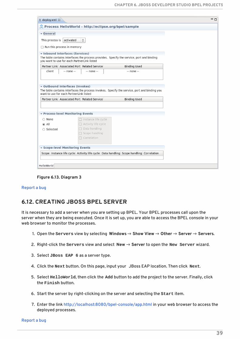
Figure 6.13. Diagram 3
Report a bug
6.12. CREATING JBOSS BPEL SERVER
It is necessary to add a server when you are setting up BPEL. Your BPEL processes call upon theserver when they are being executed. Once it is set up, you are able to access the BPEL console in yourweb browser to monitor the processes.
1. Open the Servers view by selecting Windows → Show View → Other → Server → Servers.
2. Right-click the Servers view and select New → Server to open the New Server wizard.
3. Select JBoss EAP 6 as a server type.
4. Click the Next button. On this page, input your JBoss EAP location. Then click Next.
5. Select HelloWorld, then click the Add button to add the project to the server. Finally, clickthe Finish button.
6. Start the server by right-clicking on the server and selecting the Start item.
7. Enter the link http://localhost:8080/bpel-console/app.html in your web browser to access thedeployed processes.
Report a bug
CHAPTER 6. JBOSS DEVELOPER STUDIO BPEL PROJECTS
39

6.13. CREATING CORRELATION SETS
Correlation sets provide a standardized set of properties that can be used for different messages. Thisway you do not have to set properties on each and every message. It allows for asynchronousmessaging and normalization.
1. To create a correlation for a messaging activity, go to the dashboard tab Correlation Setsand click the plus button. Set a name for the set when prompted.
2. In Properties view, click the Details tab and then click the Add button. The Select a Property dialog box appears.
3. Enter a name for the new WSDL property and its type. (Either an XSD simple type or an XMLSchema element.)
4. Click the Browse button to select a type. The Type Selection dialog box appears.
5. Click New in the Aliases section to create a new WSDL property alias.
6. Select either the Message Type, XSD Simple Type or XML scheme Element radio buttonand click Browse to select its type. Click OK.
7. A correlation can be assigned to a messaging activity (for example, Invoke, Receive, Reply).Select the activity, click Add on the Correlation property tab and choose the appropriatecorrelation set.
Report a bug
6.14. EXAMPLE BPEL COMPONENT IMPLEMENTATION
Here is an example of the BPEL component section of a SwitchYard configuration:
WARNING
The above example is for illustrative purposes only. It is best practice to editconfigurations in the SwitchYard editor plug-in. Red Hat discourages you frommanually editing the XML files.
The BPEL component contains a single implementation.bpel element that identifies the fully qualifiedname of the BPEL process. The component may also contain one or more service elements definingthe WSDL port types through which the BPEL process can be accessed.
<sca:component name="SayHelloService"> <bpel:implementation.bpel process="sh:SayHello" /> <sca:service name="SayHelloService"> <sca:interface.wsdl interface="SayHelloArtifacts.wsdl#wsdl.porttype(SayHello)"/> </sca:service></sca:component>
User Guide
40
Report a bug
6.15. STRUCTURE OF A SWITCHYARD BPEL APPLICATION
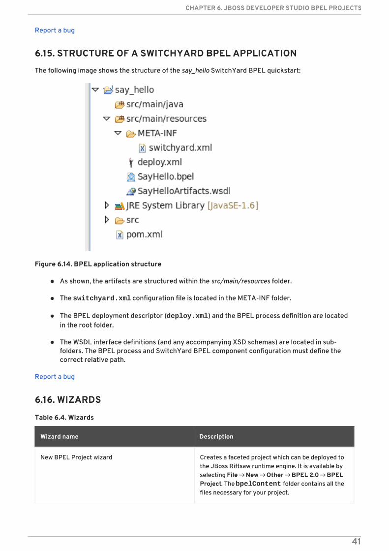
The following image shows the structure of the say_hello SwitchYard BPEL quickstart:
Figure 6.14. BPEL application structure
As shown, the artifacts are structured within the src/main/resources folder.
The switchyard.xml configuration file is located in the META-INF folder.
The BPEL deployment descriptor (deploy.xml) and the BPEL process definition are locatedin the root folder.
The WSDL interface definitions (and any accompanying XSD schemas) are located in sub-folders. The BPEL process and SwitchYard BPEL component configuration must define thecorrect relative path.
Report a bug
6.16. WIZARDS
Table 6.4. Wizards
Wizard name Description
New BPEL Project wizard Creates a faceted project which can be deployed tothe JBoss Riftsaw runtime engine. It is available byselecting File → New → Other → BPEL 2.0 → BPELProject. The bpelContent folder contains all thefiles necessary for your project.
CHAPTER 6. JBOSS DEVELOPER STUDIO BPEL PROJECTS
41

New BPEL Process File Wizard Creates a BPEL process based on one of severaltemplates defined by the wizard. The wizard assumesthe new BPEL process is to be created in the currentproject of the Project Explorer or Navigator view. If a BPEL process of the samename already exists within the project, a warningmessage is displayed before any action isperformed.
New BPEL Deployment Descriptor Use this wizard to create a Deployment Descriptor file. This file is a manifest for the webservice and is required if the BPEL process is to bedeployed to a runtime engine. The BPEL DeploymentDescriptor Editor opens once this wizard iscompleted.
Wizard name Description
IMPORTANT
BPEL artifacts must be contained somewhere within the bpelContent folder hierarchyif you intend to deploy the process. Complex projects may be organized into a folderhierarchy, but these folders must be contained within bpelContent.
The Deployment Descriptor file must be contained within the bpelContent folderand at the root of any folder hierarchy.
Report a bug
6.17. VIEWS
Table 6.5. Views
View Description
Outline The Outline view provides a structural layout ofthe BPEL process. You can view the process aseither a hierarchical tree-structured outline or as athumbnail view by pressing the associated button.
User Guide
42

Palette The primary editing, creation and viewing tools ofthe BPEL Designer are accessed from the Palette.The Palette can be docked either at the right orleft edge of the BPEL Designer main window, or itcan be detached and displayed in its own view.
The Selection Tool is used to selectindividual activities in the editors drawingcanvas. Multiple activities can be selectedby holding the CTRL or SHIFT keysin combination with left mouse click. The Marquee Tool allows selection ofgroups of activities by dragging a selectionrectangle around them.
BPEL activities are created by draggingicons from the labeled Actions, Controls and Faults palette sections(or drawers), onto the editor’s drawingcanvas. These sections can be collapsedand expanded by clicking on individualpalette section titles. They can also bepinned to prevent them from collapsing ifanother section is expanded.
The tools at the bottom of the Paletteare used to expand or shrink the drawingcanvas.
Dashboard This panel is embedded in the BPEL Designer canvasand provides a quick overview of the BPEL elementsthat are defined for the currently selected activity orBPEL process. The process name appears at the topof the Dashboard. The main Dashboard area lists allof the Partner Links, Variables,Correlation Sets and Message Exchanges currently defined for the process. Thegreen plus symbol and grey x symbol allow you toadd and delete each of these elements. In-lineediting of all element names works by selecting thename and then clicking again to enable the editor.
View Description
Report a bug
6.18. PROPERTY SECTION TABS
Table 6.6. Property Sections
Name Description
CHAPTER 6. JBOSS DEVELOPER STUDIO BPEL PROJECTS
43
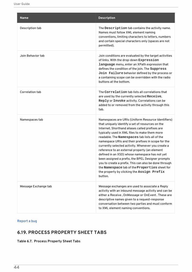
Description tab The Description tab contains the activity name.Names must follow XML element namingconventions, limiting characters to letters, numbersand certain special characters only (spaces are notpermitted).
Join Behavior tab Join conditions are evaluated by the target activitiesof links. With the drop-down Expression language menu, enter an XPath expression thatdefines the condition of the join. The Suppress Join Failure behavior defined by the process ora containing scope can be overridden with the radiobuttons at the bottom.
Correlation tab The Correlation tab lists all correlations thatare used by the currently selected Receive, Reply or Invoke activity. Correlations can beadded to or removed from the activity through thistab.
Namespaces tab Namespaces are URIs (Uniform Resource Identifiers)that uniquely identify a set of resources on theInternet. Shorthand aliases called prefixes aretypically used in XML files to make them morereadable. The Namespaces tab lists all of thenamespace URIs and their prefixes in scope for thecurrently selected activity. Whenever you create areference to an external property (an elementdefined in an XSD) whose namespace has not yetbeen assigned a prefix, the BPEL Designer promptsyou to create a prefix. This can also be done throughthe Namespace tab of the Properties sheet forthe property by clicking the Assign Prefixbutton.
Message Exchange tab Message exchanges are used to associate a Replyactivity with an inbound message activity and can beeither a Receive , OnMessage or OnEvent . These aredescriptive names given to a request-responseconversation between two parties and must conformto XML element naming conventions.
Name Description
Report a bug
6.19. PROCESS PROPERTY SHEET TABS
Table 6.7. Process Property Sheet Tabs
User Guide
44
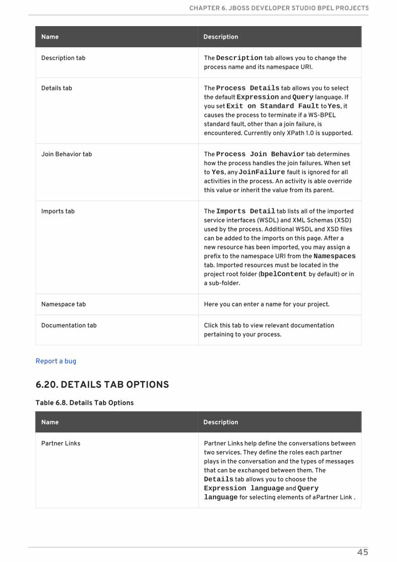
Name Description
Description tab The Description tab allows you to change theprocess name and its namespace URI.
Details tab The Process Details tab allows you to selectthe default Expression and Query language. Ifyou set Exit on Standard Fault to Yes, itcauses the process to terminate if a WS-BPELstandard fault, other than a join failure, isencountered. Currently only XPath 1.0 is supported.
Join Behavior tab The Process Join Behavior tab determineshow the process handles the join failures. When setto Yes, any JoinFailure fault is ignored for allactivities in the process. An activity is able overridethis value or inherit the value from its parent.
Imports tab The Imports Detail tab lists all of the importedservice interfaces (WSDL) and XML Schemas (XSD)used by the process. Additional WSDL and XSD filescan be added to the imports on this page. After anew resource has been imported, you may assign aprefix to the namespace URI from the Namespacestab. Imported resources must be located in theproject root folder (bpelContent by default) or ina sub-folder.
Namespace tab Here you can enter a name for your project.
Documentation tab Click this tab to view relevant documentationpertaining to your process.
Report a bug
6.20. DETAILS TAB OPTIONS
Table 6.8. Details Tab Options
Name Description
Partner Links Partner Links help define the conversations betweentwo services. They define the roles each partnerplays in the conversation and the types of messagesthat can be exchanged between them. The Details tab allows you to choose the Expression language and Query language for selecting elements of a Partner Link .
CHAPTER 6. JBOSS DEVELOPER STUDIO BPEL PROJECTS
45

Variables Variables are used in BPEL to store inbound andoutbound messages for examination andmanipulation by the business logic. They can also beused to save intermediate results and the processstate. The three kinds of variable declarations aremessages types, XML Schema types and XMLSchema elements. The Details tab allows you todefine the variable declared type and its structureby selecting from known types. Once a variable typehas been defined, the structure of the variable isshown. Clicking on the hyperlink opens the WSDL orXML Schema editor for the selected type or element.
Empty The Empty activity is a placeholder for anyundefined Basic Activity and is intended toeventually be replaced by a real activity before theprocess can actually be executed. If the BPEL engineencounters an Empty activity, it is ignored. The Details tab allows you to select one of four basicactions: Invoke , Receive , Reply and Assign .Hovering the mouse over one of the selectionbuttons displays a brief description of that activity.
Invoke The Invoke activity requires a Partner Link nameand an Operation as defined in the WSDL for thatservice. You can use the Quick Pick tree controlon the right to select the Partner Link and Operation. For one-way invocations, specify only an InputVariable . For request-response invocations youmust also specify an Output Variable . The check boxlabeled Use WSDL Message Parts Mappingprovides an alternative to using variables for therequest message.
Receive A Receive activity requires a Partner Link name andan Operation as defined in the WSDL for this service.You can use the Quick Pick tree control on theright to select the Partner Link and Operation . Apreviously defined variable can be used to hold themessage data, or the Use WSDL Message Parts Mapping check box can be set to store theincoming message in an anonymous WSDL messagevariable. The Create a new Process Instance check box, when enabled, causes theBPEL engine to start a new process. This starts anew conversation with a client.
Name Description
User Guide
46

Reply A Reply activity requires a Partner Link name and anOperation as defined in the WSDL. You can use the Quick Pick tree control at the right to select thePartner Link and Operation . A previously definedvariable can be used to provide the responsemessage data, or the Use WSDL Message Parts Mapping check box can be set to use thedata from the anonymous WSDL message variable.
Opaque Opaque activities are only used in abstractprocesses and are meant as placeholders for otheractivities yet to be determined. When you drag anddrop an Opaque activity onto the drawing canvas,the process is converted to a non-executable,abstract process.
Assign The Assign section contains an array of variablesincluding message options and managementbuttons. Additional type selection or data entrywidgets appear below the From and To comboboxes, depending on the source and target itemcategories selected in the combo boxes. Initiallythese are controls for the selection of processvariables, since the default combo box selection isVariable .
Validate The Validate details tab contains a list of variables tobe validated.
While and RepeatUntil These activities have the same details tab, whichallows you to specify an XPath expression to beevaluated for the conditional activity.
Link The Link detail tab allows you to specify a conditionthat causes Flow synchronization to be satisfied andallow the target activity to continue. This is similarto the details tab of the other conditional activities.
Pick The Pick tab allows you to specify whether theevent creates a new process instance.
OnMessage The OnMessage activity is used in Pick and eventhandlers. The Details tab allows you to specifythe Partner Link , Operation and Message Typeexpected by the activity, and the process variablethat contains the received message data.
Name Description
CHAPTER 6. JBOSS DEVELOPER STUDIO BPEL PROJECTS
47
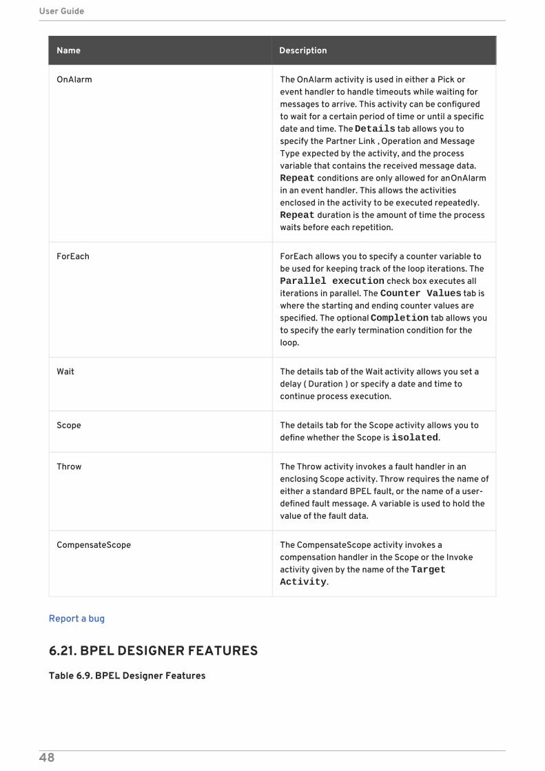
OnAlarm The OnAlarm activity is used in either a Pick orevent handler to handle timeouts while waiting formessages to arrive. This activity can be configuredto wait for a certain period of time or until a specificdate and time. The Details tab allows you tospecify the Partner Link , Operation and MessageType expected by the activity, and the processvariable that contains the received message data. Repeat conditions are only allowed for an OnAlarmin an event handler. This allows the activitiesenclosed in the activity to be executed repeatedly. Repeat duration is the amount of time the processwaits before each repetition.
ForEach ForEach allows you to specify a counter variable tobe used for keeping track of the loop iterations. The Parallel execution check box executes alliterations in parallel. The Counter Values tab iswhere the starting and ending counter values arespecified. The optional Completion tab allows youto specify the early termination condition for theloop.
Wait The details tab of the Wait activity allows you set adelay ( Duration ) or specify a date and time tocontinue process execution.
Scope The details tab for the Scope activity allows you todefine whether the Scope is isolated.
Throw The Throw activity invokes a fault handler in anenclosing Scope activity. Throw requires the name ofeither a standard BPEL fault, or the name of a user-defined fault message. A variable is used to hold thevalue of the fault data.
CompensateScope The CompensateScope activity invokes acompensation handler in the Scope or the Invokeactivity given by the name of the Target Activity.
Name Description
Report a bug
6.21. BPEL DESIGNER FEATURES
Table 6.9. BPEL Designer Features
User Guide
48

Name Description
Drawing Canvas Contains the graphical representation of the BPELprocess and is displayed when the Design tab atthe bottom of the editor window is selected. Clickingon any of the activity names activates an in-lineeditor, allowing you to edit the process name. Tofinish editing, press the ENTER key or changefocus by clicking on a different window control.
Source This tab displays the XML (text) representation ofthe process. Any changes made in one view areshown in the other. The default layout of activities istop-to-bottom, but can be changed to horizontallayout from the context menu.
Palette The primary editing, creation and viewing tools ofthe BPEL Designer are accessed from this tool.
Dashboard Provides an overview of the BPEL process.
Property Sheet Displays the properties of an activity when it isselected in the drawing canvas.
Outline This panel provides a structural view of the BPELprocess.
Report a bug
6.22. BPEL DESIGNER CONCEPTS
Table 6.10. BPEL Designer Concepts
Name Description
Assign error Hovering your mouse over this icon displays an errormessage.
Basic activities Basic activities are represented on the drawingcanvas as rounded rectangles containing an icon andthe user-defined name of the activity. The Actionssection of the Palette contains all of the basicactivities. For example: Assign , Invoke and Receive .
Start and End Every process has Start and End activities that actas placeholders for visualizing the beginning and endof the process flow.
CHAPTER 6. JBOSS DEVELOPER STUDIO BPEL PROJECTS
49
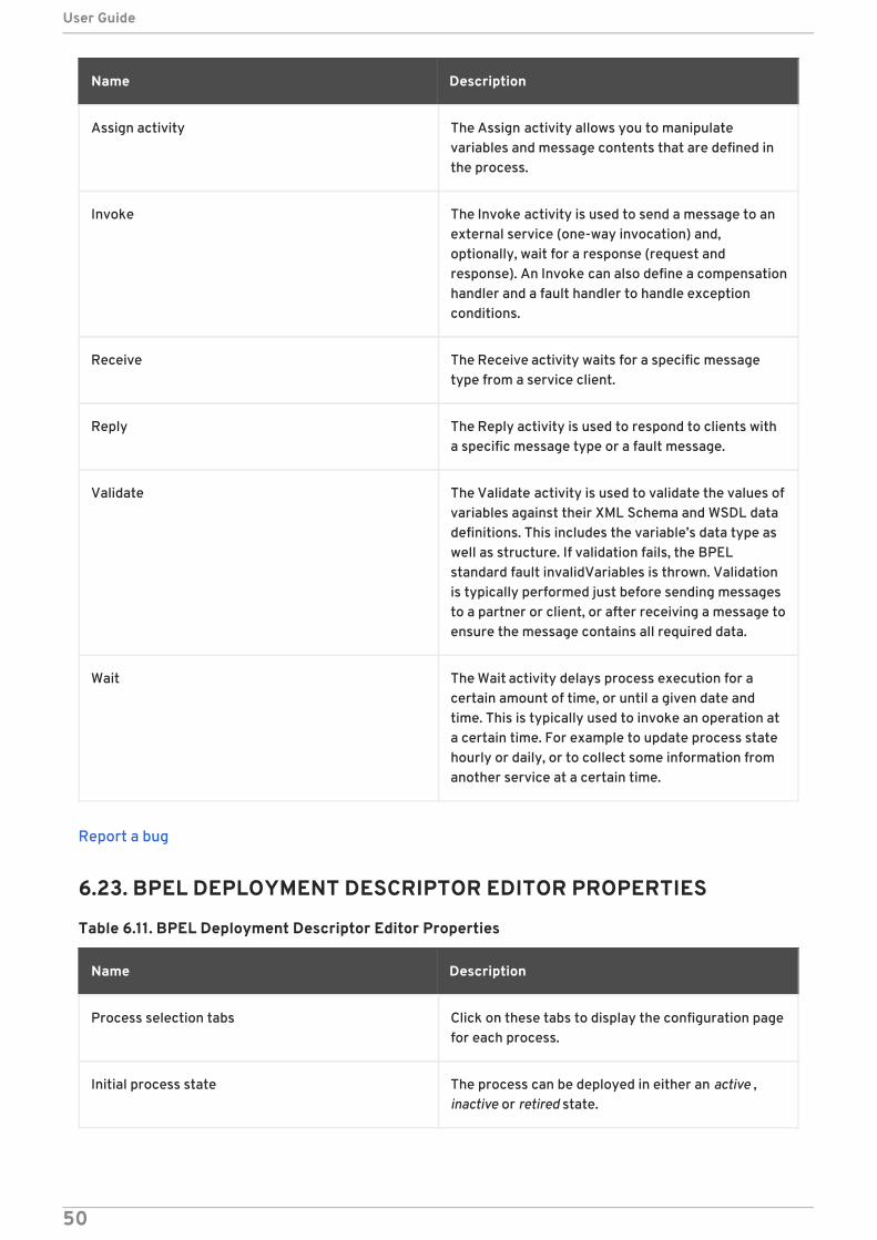
Assign activity The Assign activity allows you to manipulatevariables and message contents that are defined inthe process.
Invoke The Invoke activity is used to send a message to anexternal service (one-way invocation) and,optionally, wait for a response (request andresponse). An Invoke can also define a compensationhandler and a fault handler to handle exceptionconditions.
Receive The Receive activity waits for a specific messagetype from a service client.
Reply The Reply activity is used to respond to clients witha specific message type or a fault message.
Validate The Validate activity is used to validate the values ofvariables against their XML Schema and WSDL datadefinitions. This includes the variable’s data type aswell as structure. If validation fails, the BPELstandard fault invalidVariables is thrown. Validationis typically performed just before sending messagesto a partner or client, or after receiving a message toensure the message contains all required data.
Wait The Wait activity delays process execution for acertain amount of time, or until a given date andtime. This is typically used to invoke an operation ata certain time. For example to update process statehourly or daily, or to collect some information fromanother service at a certain time.
Name Description
Report a bug
6.23. BPEL DEPLOYMENT DESCRIPTOR EDITOR PROPERTIES
Table 6.11. BPEL Deployment Descriptor Editor Properties
Name Description
Process selection tabs Click on these tabs to display the configuration pagefor each process.
Initial process state The process can be deployed in either an active ,inactive or retired state.
User Guide
50

Inbound interfaces selection Select the WSDL port type that clients use to invokethis service.
Output interfaces selection: Each invoked service (if any) requires you to selectits port type.
Scope-level monitoring events The BPEL engine can be configured to generatemonitoring events for each Scope defined in theprocess.
Name Description
NOTE
Before a BPEL project can be deployed to the runtime engine, you must create what iscalled a deployment descriptor . This is simply a manifest file, serialized as XML, thatdescribes all of the BPEL processes and their interfaces to the BPEL engine. Thedeployment descriptor file must be created in the root folder of your project.
Report a bug
6.24. DIALOGS
Table 6.12. Dialogs
Name Description
XPath expression editor (embedded control) The XPath expression editor provides context-sensitive assistance in the form of pop-up proposals.The light bulb icon indicates that content assist isavailable by pressing the CTRL and SPACE keys simultaneously. The BPEL 2.0 specificationprovides for the definition of an XPath languageversion at the process level, as well as the activitylevel (for those activities that make use of XPath).However, only XPath 1.0 is supported by the BPELDesigner and the JBoss Riftsaw runtime engine.
Quick pick (embedded control) Tree control is used in many property pages forselecting message parts, partner links andoperations.
CHAPTER 6. JBOSS DEVELOPER STUDIO BPEL PROJECTS
51

Type selection This dialog is displayed whenever the BPEL Designerrequires you to select a message, message part,XML Schema type or XML element.
1. Type Name: Used to limit the itemsdisplayed in the Matches (4) list. Onlyitems that begin with the text in this filterare displayed.
2. Show XSD Types: Can be used to limitwhere the editor searches for XSD files.
3. Filter: Further reduces the number ofmatches according to types.
4. Matches: Displays the items matching theselected filters. Selecting an item in this listupdates the Type Structure (5) treeview.
5. Type Structure: Displays the structureof the item selected in the Matches (4)list. Depending on the type of itemrequested, you may need to select an itemfrom this tree control as well; the OK buttonbeing enabled is an indicated of a selectionbeing required here.
6. Add Schema: If the required XML Schemahas not been resolved, you can add it to theprocess’ imports by clicking this button.
Name Description
Report a bug
6.25. CHEAT SHEETS
The Cheat Sheets option allows you to view tutorials. This helps you teach yourself how to use JBossDeveloper Studio and its plug-ins. By playing around with them, you can gain a better understanding ofhow the studio works and what you can do with it.
Procedure 6.3. Task
1. Access the cheat sheet by clicking Help → Cheat Sheets.
2. The cheat sheet opens in a separate view as show below. Click on the Click to begin link tobegin.
User Guide
52

Figure 6.15. Diagram 1
3. You can now view tutorials for plug-in tools.
Report a bug
6.26. CONTEXT MENU
Access the context menu by right-clicking over an activity figure on the drawing canvas. A sub-menuappears. The items within the Add sub-menu appends a new activity after the current one while thosewithin the Insert Before sub-menu inserts the new activity before the current one.
Report a bug
CHAPTER 6. JBOSS DEVELOPER STUDIO BPEL PROJECTS
53

CHAPTER 7. JBOSS DEVELOPER STUDIO GUVNOR TASKS
7.1. GUVNOR REPOSITORY EXPLORING PERSPECTIVE
There are different perspectives which you can use to view your files in JBoss Developer Studio. Youdon't have to have only one perspective open at all times. You can switch between them to accessdifferent plug-ins in the same session.
1. In the JBoss Developer Studio workbench menu, select Window → Open Perspective → Otherto view the perspective list.
2. Choose the perspective you wish to use. JBoss Developer Studio standard views such as Properties and Resource Navigator are useful.
Figure 7.1. Perspective list
Report a bug
7.2. CREATING A NEW GUVNOR CONNECTION
JBoss Developer Studio comes with a wizard for creating Guvnor connections. Adding newconnections allows you to configure repositories and access Guvnor files. You can modify these inJBoss Developer Studio.
1. Open a new connection.
2. Start the Guvnor Connection wizard in one of the following ways:
User Guide
54

Select File → New → Other → Guvnor → Guvnor repository location within JBossDeveloper Studio.
Go to the Guvnor Repositories view using the drop-down menu.
Use the menu button to select a new connection. This is added to JBoss Developer Studioautomatically.
Report a bug
7.3. CONFIGURING THE GUVNOR CONNECTION WIZARD
Once you have created a new Guvnor connection, you can configure it. Most of the fields have defaultvalues already filled out, but you are able to change these to be more applicable. You can list yourGuvnor repository URLs here.
1. Default values appear in the Location, Port and Repository fields. You can edit thesefields using their corresponding text boxes.
2. To input a Guvnor repository URL into the respective fields, drag and drop it into the Location field.
IMPORTANT
When using JBoss Developer Studio tooling, you cannot access Guvnor data ifthis Guvnor is deployed on a secured HTTP (HTTPS).
3. The EGT calls the Guvnor repository at various times, such as when it is determining if anyresource updates are available. If you use session authentication, the authentication dialogappears at different times during the JBoss Developer Studio workbench session, dependingon what actions you take. We recommend saving the authentication information in the JBossDeveloper Studio keyring.
Click on save username and password to save your details into the JBoss DeveloperStudio workbench's keyring file.
NOTE
If the authentication information is not stored in the keyring, then the EGT usesa session authentication. This means that the credentials supplied are only usedduring the lifetime of the JBoss Developer Studio workbench instance.
NOTE
If an authentication failure error occurs, you can retry the same operation andsupply different authentication information.
CHAPTER 7. JBOSS DEVELOPER STUDIO GUVNOR TASKS
55
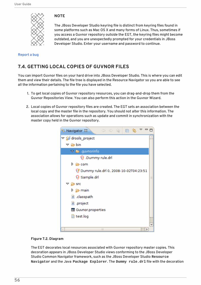
NOTE
The JBoss Developer Studio keyring file is distinct from keyring files found insome platforms such as Mac OS X and many forms of Linux. Thus, sometimes ifyou access a Guvnor repository outside the EGT, the keyring files might becomeoutdated, and you are unexpectedly prompted for your credentials in JBossDeveloper Studio. Enter your username and password to continue.
Report a bug
7.4. GETTING LOCAL COPIES OF GUVNOR FILES
You can import Guvnor files on your hard drive into JBoss Developer Studio. This is where you can editthem and view their details. The file tree is displayed in the Resource Navigator so you are able to seeall the information pertaining to the file you have selected.
1. To get local copies of Guvnor repository resources, you can drag-and-drop them from theGuvnor Repositories View. You can also perform this action in the Guvnor Wizard.
2. Local copies of Guvnor repository files are created. The EGT sets an association between thelocal copy and the master file in the repository. You should not alter this information. Theassociation allows for operations such as update and commit in synchronization with themaster copy held in the Guvnor repository.
Figure 7.2. Diagram
The EGT decorates local resources associated with Guvnor repository master copies. Thisdecoration appears in JBoss Developer Studio views conforming to the JBoss DeveloperStudio Common Navigator framework, such as the JBoss Developer Studio Resource Navigator and the Java Package Explorer. The Dummy rule.drl file with the decoration
User Guide
56
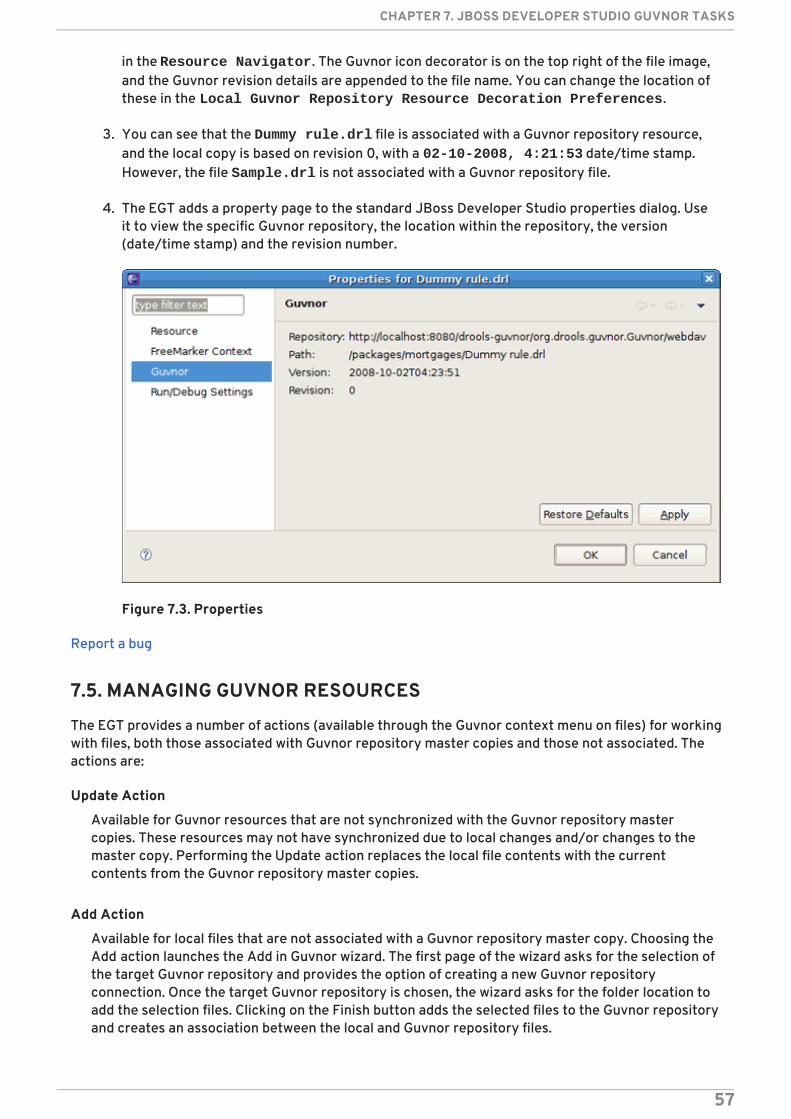
in the Resource Navigator. The Guvnor icon decorator is on the top right of the file image,and the Guvnor revision details are appended to the file name. You can change the location ofthese in the Local Guvnor Repository Resource Decoration Preferences.
3. You can see that the Dummy rule.drl file is associated with a Guvnor repository resource,and the local copy is based on revision 0, with a 02-10-2008, 4:21:53 date/time stamp.However, the file Sample.drl is not associated with a Guvnor repository file.
4. The EGT adds a property page to the standard JBoss Developer Studio properties dialog. Useit to view the specific Guvnor repository, the location within the repository, the version(date/time stamp) and the revision number.
Figure 7.3. Properties
Report a bug
7.5. MANAGING GUVNOR RESOURCES
The EGT provides a number of actions (available through the Guvnor context menu on files) for workingwith files, both those associated with Guvnor repository master copies and those not associated. Theactions are:
Update Action
Available for Guvnor resources that are not synchronized with the Guvnor repository mastercopies. These resources may not have synchronized due to local changes and/or changes to themaster copy. Performing the Update action replaces the local file contents with the currentcontents from the Guvnor repository master copies.
Add Action
Available for local files that are not associated with a Guvnor repository master copy. Choosing theAdd action launches the Add in Guvnor wizard. The first page of the wizard asks for the selection ofthe target Guvnor repository and provides the option of creating a new Guvnor repositoryconnection. Once the target Guvnor repository is chosen, the wizard asks for the folder location toadd the selection files. Clicking on the Finish button adds the selected files to the Guvnor repositoryand creates an association between the local and Guvnor repository files.
CHAPTER 7. JBOSS DEVELOPER STUDIO GUVNOR TASKS
57

NOTE
The snapshot folder in the Guvnor repository is read-only for EGT, and hence notvisible as a candidate location in this wizard. The Guvnor repository webadministration tools must be used to add snapshot content.
NOTE
The wizard does not allow existing Guvnor repository files to be overwritten. Anothertarget location must be chosen.
Commit Action
Enabled for Guvnor repository associated files that have local changes. The Commit action writesthe changes back to the associated Guvnor repository files and update the association for the newrevision created.
If a local change is based on an older revision of a file than is currently in the Guvnor repository, theCommit action asks whether you wish to overwrite the current version in the Guvnor repositorywith the local content. When such conflicts occur, you should use the JBoss Developer StudioGuvnor version tools and the JBoss Developer Studio standard tools to determine the differencesand merge content based on the current version.
Show History Action
Populates the Guvnor Resource History View with revision history for the selected file.
Compare with Version Action
Enabled for singular Guvnor repository associated files. This action first opens a wizard asking forthe version for comparison (with the local file contents). Once the revision is selected, the actionopens the JBoss Developer Studio Compare editor (in a read-only mode) which shows thedifferences in the two versions.
Switch to Version Action
Enabled for singular Guvnor repository associated files. It first prompts for the selection of aversion. Once the version is selected, the Switch to Version action replaces the local file contentswith those from the revision selected.
Delete Action
Enabled for one or more Guvnor repository associated files. After the action has been confirmed,the Delete action removes the files in the Guvnor repository and deletes local metadata for theGuvnor repository association.
Disconnect Action
Enabled for one or more Guvnor repository associated files. Removes local metadata from theGuvnor repository association.
Report a bug
7.6. RESOURCE FROM GUVNOR WIZARD
User Guide
58

This wizard allows you to copy files to your local workspace from the Guvnor repository. Once added,you can access them within Guvnor. They are listed as resources which you can call on.
1. Open the wizard by selecting File → Import → Guvnor → Resource from Guvnor or File →New → Other → Guvnor → Resource from Guvnor .
2. You are prompted to enter the source Guvnor repository. You can also create a new Guvnorrepository connection.
3. Once the source Guvnor repository is chosen, the wizard prompts for the resources to becopied.
4. Finally, choose the target location for the files in the local workspace.
5. On completion the wizard copies the selected files from the Guvnor repository to the localworkspace. If a file with the same name already exists in the destination, you are prompted torename it.
Report a bug
7.7. GUVNOR REPOSITORIES VIEW
The Guvnor Repositories view contains tree structures representing the contents of Guvnorrepositories. You can perform the following actions under the resources in the Guvnor Repositories view:
Table 7.1. Guvnor Repositories View Actions
Action Description
Create a new Guvnor repository connection Use the wizard to create a new connection byselecting File → New → Other → Guvnor → Guvnorrepository location in JBoss Developer Studio.
Remove a Guvnor repository connection Click Delete
( ) to remove a repository
connection.
Refresh Guvnor repository resources. Use the Refresh context menu item to reload thetree for the selected node.
"Drill-into" functionality Use icons on the toolbar such as the Home, Go Back and Go Into buttons to navigate deeplynested structures.
Go Home button ( ) Returns the tree to the top-level structure.
Selecting a file in the Guvnor repository Doing this causes the JBoss Developer Studio Properties view to display the details of that file.
Report a bug
CHAPTER 7. JBOSS DEVELOPER STUDIO GUVNOR TASKS
59
7.8. GUVNOR RESOURCE HISTORY VIEW
The Guvnor Resource History view displays details about the revision history of the files you haveselected. The Guvnor Resource History view is populated by Show History actions in either thelocal Guvnor context menu or in the context menu for a Guvnor repository file in the GuvnorRepositories View.
Report a bug
7.9. CONFIGURING THE GUVNOR RESOURCE HISTORY VIEW
This enables you to see the revision history of your project. If you need to know when part of yourproject was changed, you are able to go through its history and see when and what modifications weremade. This simplifies keeping track of changes.
1. Select Show History in the local Guvnor context menu. Alternatively, select it in thecontext menu for a Guvnor repository file in the Guvnor Repositories View.
2. The Guvnor Resource History view is refreshed to display the revision history.
3. To open a JBoss Developer Studio read-only editor with the revision contents, double-click ona revision row or select the Open (Read only) option from the context menu.
4. Click on the Save As option when a file is open in a read-only editor to save a local writablecopy of the contents. (This does not associate the file created with its Guvnor source.)
Report a bug
7.10. GUVNOR PREFERENCES
The EGT provides a preference page in the Guvnor category. The preferences cover two categories:
Guvnor repository connections
Local Guvnor repository resource decorations
Report a bug
7.11. GUVNOR REPOSITORY CONNECTION PREFERENCES
There are two preferences that can be set for Guvnor repository connections. These are used whencreating new connections:
Table 7.2. Guvnor Repository Connection Preferences
Preference Description
Default Guvnor repository URL template Simplifies the process of creating additional similarconnections by changing part of the field, such as thehost name.
User Guide
60
Authentication information Defines whether or not authentication informationshould be saved in the JBoss Developer Studioplatform key-ring by default. As with the Guvnorrepository URL template, this decision can bedetermined when creating the connection.
Preference Description
Report a bug
7.12. LOCAL GUVNOR REPOSITORY RESOURCE DECORATIONPREFERENCES
This category of preferences provided by the EGT can be used to define how the decoration of localresources associated with Guvnor repository resources is presented. Since the Guvnor repository isnot a substitute for a SCM, and since SCM tools in JBoss Developer Studio tend to decorate localresources, it is useful to be able to control how the EGT decorates its local resources to avoid conflictswith SCM packages.
In the File Decoration section of the preference page, you can choose the location (Top right, Topleft, Bottom right, Bottom left) of the decoration icon, or you can choose not to display it. In the Textsection, you can format the Guvnor metadata which is appended to the file names.
Whether to show an indicator (>) when the local file has changes not committed back to theGuvnor repository
Whether to show the revision number
Whether to show the date/time stamp
Any changes to these preferences take effect immediately upon clicking the Apply and then OKbuttons.
Report a bug
CHAPTER 7. JBOSS DEVELOPER STUDIO GUVNOR TASKS
61

APPENDIX A. REVISION HISTORY
Revision 6.0.0-27 Monday February 23 2015 B LongVersion number updated from 6 to 6.0 for consistency.
Revision 6.0.0-26 Tuesday January 13 2015 Nilam ShendyeUpdated for Red Hat JBoss Fuse Service Works 6.0
Revision 6.0.0-25 Wednesday December 17 2014 Anshu Mahajan
User Guide
62