Red Dragon Row Crop Flamer Unit - Flame technology … FLAME ENGINEERING, INC. • 1-800-255-2469...
30
Red Dragon Row Crop Flamer Unit Owners Manual For Unit Numbers 2-RU, 4-RU, 6-RU and 8-RU AGRICULTURAL EQUIPMENT ®
Transcript of Red Dragon Row Crop Flamer Unit - Flame technology … FLAME ENGINEERING, INC. • 1-800-255-2469...

Red Dragon Row Crop Flamer Unit
Owners Manual
For Unit Numbers 2-RU, 4-RU, 6-RU and 8-RU
AGRICULTURAL EQUIPMENT®

FLAME ENGINEERING, INC. • 1-800-255-2469 • Fax 1-785-222-3619 • www.FlameEngineering.com

FLAME ENGINEERING, INC. • 1-800-255-2469 • Fax 1-785-222-3619 • www.FlameEngineering.com 1
Table of Contents
Flaming History Page 2
General Row Crop Flaming Information Pages 3-4
Row Crop Flaming Unit Parts List Page 5
Assembly Instructions Pages 6-9
Check List For Daily Start Up - Leak Test and Primary Torch Adjustment Page 10
Assembly Diagrams A-E2 11-15
Control Head Assembly Diagrams Page 16-18
LP-Gas Hose Assembly Diagrams Page 19-21
Control Switch Assembly Diagram Page 22
Crop Flaming Recommendations Chart Page 23
Proper Purging of LP-Gas Container Page 24-25
Vacuum Pre-Purged Domestic Tanks Page 26
If You Have Questions Page 27
Trouble Shooting Tips Page 27

FLAME ENGINEERING, INC. • 1-800-255-2469 • Fax 1-785-222-3619 • www.FlameEngineering.com2
Flame Cultivation History
In 1938 an Alabama farmer had an idea. Price McLemore discovered that the flame from a keroseneburner would destroy the weeds in his cotton and corn. A machine was assembled and several acres of Mr.McLemore’s corn and cotton were flame cultivated.
This first known attempt at flame cultivation from a tractor mounted unit consisted of two keroseneburners per row on a two row unit. The fuel tank was pressurized with a bicycle pump which would supplythe necessary fuel to the four self-generating burners. This must have been quite a site to the neighboringfarmers as he drove the tractor with one hand and pumped like crazy with the other hand. It was crude butvery effective.
For several years Mr. McLemore attempted to arouse interest in his process by presenting it to agricul-tural research institutions and experiment stations. Most of his efforts were met with disbelief and laughter.
Finally, in 1942 Louisiana State University began experimenting with flame weeding in sugar cane,under the direction of Dr. H. T. Barr. The Delta Branch Experiment Station included flame cultivation intheir 1943 cotton weed control project, and in 1944 they began work with corn and soybeans. Results ofthese experiments were very promising, especially in cotton, and generated a great deal of interest amongfarmers in Louisiana, Mississippi, and Arkansas. It is estimated that by 1946 there were at least 1,000 flamecultivators in the cotton fields of the Mississippi Delta.
Soon after, the International Harvester Company began researching flame cultivation and developed animproved cast iron burner. The burner produced a relatively flat, fan shaped flame which improved thecoverage area as the unit moved through the crop rows. This project was later abandoned due to a corporatedecision.
One of the next developments in flame cultivation was the addition of a third burner, sometimes undera hood, to control the weeds and grass between the rows. This, however, was not universally accepted,according to J.W. Gotcher, Sr., President of Gotcher Engineering and Manufacturing Co., an early manufac-turer of flaming equipment. “Most growers were of the opinion that it was necessary to stir the soil at reg-ular intervals throughout much of the growing season for maximum plant growth and production” he said.The third burner technique eventually became more popular when frequent rains caused the fields to be toowet to cultivate in the conventional manner.
It is estimated that by 1960, 15,000 flaming units were in use. Most flamers were used in the cottonfields, a smaller amount were used in corn and soybeans. About this same time interest was growing in thepractice of nonselective flaming of mint and alfalfa.
In the years that followed, research has proven that flame cultivation can be used on 30 to 40 differentcrops. Although extensive research has been conducted with corn, cotton, and soybeans, many other cropssuch as casterbeans, blueberries, strawberries, radish, lettuce, potatoes, asparagus, grapes, fruit trees, andthe Australian tea tree have all been successfully flame cultivated. Recent innovations such as more effi-cient burners and more reliable electric and manual control valves have made flame cultivation safer andmore adaptable.

FLAME ENGINEERING, INC. • 1-800-255-2469 • Fax 1-785-222-3619 • www.FlameEngineering.com 3
General Row Crop Flaming Information
Flaming was a very popular practice on corn, cotton and other row crops prior to the introduction ofherbicides and pesticides (see Row Crop Flamer History page 2). In fact, so much research was performedin the first half of this century that flaming was fast-becoming the primary method of weed control in cot-ton. So, why did it nearly disappear, only to reappear in the 1990s? Were it not for the abundance of cheapherbicides in the 1960s and early 1970s (and the relatively high price of LP at the time), flaming may verywell have gone on to become “the” method of controlling weeds and grasses in the crop row. Due to recenthigh costs and the environmental issues associated with chemicals, flaming is making a very successfulcomeback across the country and abroad.
The recent rebound began in the food industry where growers began to see premiums for crops raisednaturally. Farmers from all areas now realize the economic advantages and the flexibility flaming allows ina wide variety of crops. In fact, many crops are so resilient to flame weeding that there is almost no notice-able effect to the plant. Taking the matter to extremes in a recent university study, researchers actually over-flamed a surplus test plot of established milo at 1 1/2 m.p.h. The leaves of the milo were damaged andeventually turned white, however, this same crop yielded comparatively to unflamed plants in the sameplot. While we do not recommend overexposing your crops, this does illustrate an important aspect of flam-ing. When lower leaves are singed the plant puts all of its energy toward saving the upper leaves which areprimarily responsible for grain, boll or fruit production. Roots remain undamaged and higher yields areoften the result.
By staggering torches and flaming at the base of the crop, most leaves are not exposed and each plantreceives only a split second of intense heat. Small weeds and grasses die almost instantly due to the expan-sion of cell tissues. Larger weeds die or are severely stunted, allowing the hardier row crop to shade outcompetitive weeds and grasses. In addition, you may reenter the field to pick up stragglers at a much moreaffordable rate than chemical and without risk to the crop.
It is not necessary to burn the weeds to a crisp, but rather raise the temperature in the plant fibers toinjure cell structure. This will destroy the plant’s ability to take in moisture and will, in a very short time,cause the plant to wither and die. Because the crops are green and growing there is very little smoke. Theamount of time in which the flame must be in contact with the weed will vary with type and size, but inmost cases 1/10 of a second is adequate. Smaller, more tender plants are much more susceptible to flamingthan mature growth, therefore, the crop should be larger than the weeds or grass to be controlled. Someplants are more resistant than others to the flaming. For this reason, speed, torch angle, fuel pressure andother variables should be considered when preparing to flame.
When adjusting the torch, apply enough heat to destroy the weeds and grass without causing damageto the crop. There will be some stress to the plant, however it should recover in a very short period of time.
Initially, set the torch at an angle of 45 to 30 degrees horizontal, with burners 4 to 10 inches from thecrop and a pressure of 65 PSI. Tractor speed will range from 3 to 6 m.p.h. Generally the torches are stag-gered which allows one flame to move through the row and not collide with the opposite flame. By direct-ing flame into the crop row from both sides, more complete coverage and faster ground speeds are possible.

FLAME ENGINEERING, INC. • 1-800-255-2469 • Fax 1-785-222-3619 • www.FlameEngineering.com4
General Information Continued
Many weeds and grasses that adversely effect crops can be successfully controlled with flame cultiva-tion, however this method should not be considered a complete cure-all. Flaming has sometimes been con-sidered a last resort, when other methods have failed. When the weeds have become too large or too preva-lent to control with other methods, flaming may not be totally effective either.
If there is weed pressure before planting, a broadcast flaming can be used. It may require turning thetorches to the back and spacing from side to side so that it will not leave streaks.
Quite a number of crops have the ability to regrow flamed off tops of young plants. Onions, corn,grain sorghums, potatoes, and other crops may be flamed if the early stand is heavily pressured by weedpopulation. As these crops emerge from the soil they can be flamed to control weeds as long as the “livepoint” of the plant is below the ground. If the plant is at the stage it will come back.
It is important to remember that flaming can be used for weed and grass control, and also for insectcontrol. It has proven to be extremely effective in controlling the alfalfa weevil and the Colorado potatobeetle.

FLAME ENGINEERING, INC. • 1-800-255-2469 • Fax 1-785-222-3619 • www.FlameEngineering.com 5
Red Dragon Row Crop Flaming Unit Parts List(For Complete Units 2-RU, 4-RU, 6-RU, and 8-RU.)
Off Part *Reference Part QTY QTY QTY QTY List Number Letter Description 2-RU 4-RU 6-RU 8-RU
RU-1 Tank Valve Guard 1 1 1 1RU-2 Standard Frame 1 1 1 1RU-3 36 Frame Stand 2 2 2 2RU-4 31 Frame Stand 2 2 2 2G-20 Retaining Pins For RU-3 & RU-4 4 4 4 4325 Hydaulic Cylinders 0 0 2 2
HR400 Hydraulic Hose Assembly 0 0 1 1RUR-12 Right Boom Extension 0 1 0 0RUL-12 Left Boom Extension 0 1 0 0RUR-13 Right Boom Arm 0 0 1 1RUL-13 Left Boom Arm 0 0 1 1
KU-5 B Torch Bar 4 8 12 16 RU-10 C Torch Bracket w/set screws 3 5 7 9 RU-11 F Tool Bar Bracket w/bolts 3 5 7 9 G-20 J Retaining Pin 3 5 7 9 HP2S G 1/4" LPG Hose 2' 4 8 12 16 V-326 K Ball Valve 3 5 7 9 RU-9 L Skid Plate with 7/16 x 3 1/2” Bolt & Lock Nut 3 5 7 9RU-5 E Tool Bar Skid Leg with brass fittings 3 5 7 9
A Liquid Torch 4 8 12 16 LT-6 D LPS Bracket on Torch 4 8 12 16
100-117-012 H 1/4 x 6 Nipple 4 8 12 16 F-776* I Female x Male Flared Fitting 4 8 12 16 HP65T 1/4" LPG Hose 5 1/2' 3 3 5 7HP8S 1/4" LPG Hose 8' 2 2 2
CS601-2-4 Control Box w/Switches (2 & 4 Row Units) 1 1 CS601-6-8-12 Control Box w/Switches (6 & 8 Row Units) 1 1
C 12 WP Control Assembly 1 C 14 WP Control Assembly 1C 16 WP Control Assembly 1C 18 WP Control Assembly 1
Assembly Packet 1 1 1 1Packet IncludesZip Ties
L2002* Spark Lighter 1 1 1 1 T-Wrench 1 1 1 1
LD-1 Leak Detector 1 1 1 1 VT 2 1/2-24 CE Complete Vapor Torch Kit for Lighting Burners 1 1 1 1
*Reference Letter to Tool Bar with Skid Leg Assembly Diagram on Page 15

FLAME ENGINEERING, INC. • 1-800-255-2469 • Fax 1-785-222-3619 • www.FlameEngineering.com6
Red Dragon Row Crop Flamer UnitAssembly Instructions
(Unit Numbers 2-RU, 4-RU, 6-RU and 8-RU)
IMPORTANT!Always start with a clean LP-Tank & use a fuel strainer!
NOTE: All Right Side or Left Side indications are made as if facing the tool bar side of tankframe. All Front indications refer to the 3-point adaptor side of tank frame. All Back indica-
tions refer to the tool bar side of tank frame.Refer to assembly drawings on pages 12-21 in addition to the following instructions.
1. Unpack all parts and check against parts list. Refer to illustrations for part numbers and positions.
2. Attach your tractor to the three point hitch and raise the fuel tank frame (RU-2) to a raised position. Lowerthe fuel tank frame leg stands (RU-3 rear and RU-4 front) to the storage position (extended downward) andpin with retaining pins (G-20). Lower the frame so it will rest on the legs. (See Assem. Diagram A, Pg. 11)
3. When installing the fuel tank to the frame, position the tank so it will be centered.
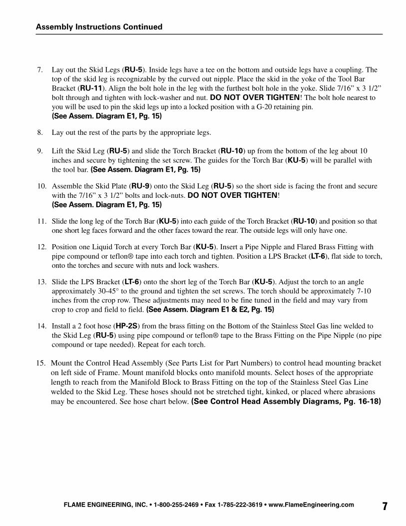
4. Place valve protector on fuel tank and secure by using the two cables. Install bolt ends of cable into the holes on front of the tank frame and secure with 1/2” lock-nuts. Run cables up through the cable brackets on the valve guard and down the back side of the tank through the cable holes on the back side of the tank frame. Secure with 1/2” lock-nuts. Tighten the cables as needed. (See Assem.Diagram B, Pg. 12)
5. Extension/Boom Assembly for 4, 6, and 8 Row Units (2 Row Units Require Frame Only)
Four Row UnitSlide extensions (RU-12 marked left and right), into the toolbar of the frame and bolt with 5/8” x 4” bolts through boom tabs and extension and tighten with lock washers and nuts. (See Assem. Diagram C, Pg. 13)
Six and Eight Row UnitLift boom arms (R-13 for 6-Row Unit and R-14 for 8-Row Unit) with tabs up and 45 degree braces towardthe front to align with boom tabs and bolt with 5/8” x 4” bolts, and lock-nuts. CAUTION: DO NOT overtighten or the boom arms may not raise and lower smoothly. (See Assem. Diagram D, Pg. 14)
Using 7/16” x 3” bolts, and lock-nuts, mount pull arm clevis assemblies to top supports. Bolt idler pull armassemblies (marked right and left) to clevis arms and then to boom arms. (See Assem. Diagram D, Pg. 14)
Pin the base of the hydraulic cylinders (325) into the hydraulic cylinder mounting tab on the frame. Pin the other end of the cylinder to the boom tab. (See Assem. Diagram D, Pg. 14)
6. Lay out the Tool Bar Brackets (RU-11). Mark,on the tool bar, the centers of your field rows (up to 36” on center). As you face the tool bar the U-shaped tool bar bracket is placed on the tool bar so the bolt holes are towards you. Bolt with provided bracket bolts, lock-washers, and nuts in the anticipated position. Someadjustment may be required in the field. You will have one more Tool Bar Bracket (RU-11) than the rows you will cover. These leg assemblies are identical except for the outside row assemblies which contain only one Torch Bar (KU-5) and one hose. (See Assem. Diagram E1, Pg. 15)
FLAME ENGINEERING, INC. • 1-800-255-2469 • Fax 1-785-222-3619 • www.FlameEngineering.com 7
7. Lay out the Skid Legs (RU-5). Inside legs have a tee on the bottom and outside legs have a coupling. The top of the skid leg is recognizable by the curved out nipple. Place the skid in the yoke of the Tool Bar Bracket (RU-11). Align the bolt hole in the leg with the furthest bolt hole in the yoke. Slide 7/16” x 3 1/2”bolt through and tighten with lock-washer and nut. DO NOT OVER TIGHTEN! The bolt hole nearest to you will be used to pin the skid legs up into a locked position with a G-20 retaining pin.(See Assem. Diagram E1, Pg. 15)
8. Lay out the rest of the parts by the appropriate legs.
9. Lift the Skid Leg (RU-5) and slide the Torch Bracket (RU-10) up from the bottom of the leg about 10 inches and secure by tightening the set screw. The guides for the Torch Bar (KU-5) will be parallel with the tool bar. (See Assem. Diagram E1, Pg. 15)
10. Assemble the Skid Plate (RU-9) onto the Skid Leg (RU-5) so the short side is facing the front and secure with the 7/16” x 3 1/2” bolts and lock-nuts. DO NOT OVER TIGHTEN! (See Assem. Diagram E1, Pg. 15)
11. Slide the long leg of the Torch Bar (KU-5) into each guide of the Torch Bracket (RU-10) and position so that one short leg faces forward and the other faces toward the rear. The outside legs will only have one.
12. Position one Liquid Torch at every Torch Bar (KU-5). Insert a Pipe Nipple and Flared Brass Fitting with pipe compound or teflon® tape into each torch and tighten. Position a LPS Bracket (LT-6), flat side to torch,onto the torches and secure with nuts and lock washers.
13. Slide the LPS Bracket (LT-6) onto the short leg of the Torch Bar (KU-5). Adjust the torch to an angle approximately 30-45° to the ground and tighten the set screws. The torch should be approximately 7-10 inches from the crop row. These adjustments may need to be fine tuned in the field and may vary from crop to crop and field to field. (See Assem. Diagram E1 & E2, Pg. 15)
14. Install a 2 foot hose (HP-2S) from the brass fitting on the Bottom of the Stainless Steel Gas line welded to the Skid Leg (RU-5) using pipe compound or teflon® tape to the Brass Fitting on the Pipe Nipple (no pipecompound or tape needed). Repeat for each torch.
15. Mount the Control Head Assembly (See Parts List for Part Numbers) to control head mounting bracketon left side of Frame. Mount manifold blocks onto manifold mounts. Select hoses of the appropriate length to reach from the Manifold Block to Brass Fitting on the top of the Stainless Steel Gas Line welded to the Skid Leg. These hoses should not be stretched tight, kinked, or placed where abrasions may be encountered. See hose chart below. (See Control Head Assembly Diagrams, Pg. 16-18)
Assembly Instructions Continued

FLAME ENGINEERING, INC. • 1-800-255-2469 • Fax 1-785-222-3619 • www.FlameEngineering.com8
Assembly Instructions Continued
16. 8 ROW UNIT: Starting with the left control assembly looking forward, number the holes of the mani-fold from left to right (counter clockwise) 1, 2, 3, 4, 5. Hole number 3 should be plugged. Number the ports in the right manifold in the same manner 6, 7, 8, 9, 10. (See Hose Assem. Diagrams, Pgs. 20-22)
6 ROW UNIT: Starting with the left control assembly looking forward, number the holes of the mani-fold from left to right (counter clockwise) 1, 2, 3, 4, 5. Hole number 3 should be plugged. Number the ports of the right control assembly cross in the same manner, 6, 7, 8. (See Hose Assem. Diagrams, Pgs. 20-22)
4 ROW UNIT: Number 1, 2, 3, 4, 5. (See Hose Assem. Diagrams, Pgs. 20-22)
2 ROW UNIT: Number 1, 2, 3. (See Hose Assem. Diagrams, Pgs. 20-22)
17. Attach hoses as follows being sure to apply Teflon tape or pipe compound (LP Gas approved) to each taper threaded connection. It is not necessary to use pipe compound on flare type fittings.
Burner Supply Hose Lengths in FeetPosition 2-RU 4-RU 6-RU 8-RU
1 5 1/2 8 8 82 5 1/2 5 1/2 5 1/2 5 1/23 5 1/2 5 1/2 PLUG PLUG4 NA 5 1/2 5 1/2 5 1/25 NA 8 5 1/2 5 1/26 NA NA 5 1/2 5 1/27 NA NA 5 1/2 5 1/28 NA NA 8 5 1/29 NA NA NA 5 1/210 NA NA NA 8
18. Tighten all connections securely being sure you have at least 3 threads in the connection (3 complete revolutions).
19. Route hoses to Skid Legs in sequence. Number one port would be the left most torch position. Number2 would be the next position to the right and so on. Tighten swivels on hoses to Flare Fittings on Skid Leg. No teflon or pipe thread compound necessary. (See Hose Assem. Diagrams, Pgs. 19-21)
20. A fuel strainer and solenoid is included with your Red Dragon Row Crop Flamer Kit (See Drawing for2, 4, 6 or 8 row). This should be mounted as near to the supply tank as possible. Be sure to observe theflow direction arrow (or instructions). (See Control Head Assem. Diagrams, Pgs 16-18)
21. Next route the main supply hose from the strainer and solenoid to the control head or heads. Tighten flare fitting securely. No pipe tape or compound is necessary at the flare fittings.

FLAME ENGINEERING, INC. • 1-800-255-2469 • Fax 1-785-222-3619 • www.FlameEngineering.com 9
22. Shut off bypass valve on control head by turning clockwise until completely closed. DO NOT ATTACH ELECTRICAL WIRE ASSEMBLY AT THIS TIME.
CAUTION:Protect all tank valves, fittings, hose connections etc… Rollover protection is a must.
ALL procedures from this point on should be done outside or in a well ventilated area.
IMPORTANT:START WITH A CLEAN TANK (We recommend only new tanks)
Always begin with a NEW, clean, purged, liquid tank. This equipment requires thetank to be equipped with top mounted liquid and vapor withdrawal valves. Always per-form the Methanol Injection Process, as described in this manual, before filling the tank
with LP-Gas. Use clean fuel to avoid line/torch blockage.
23. Open supply tank valve slowly, about one turn. Listen for leaks. If a leak is heard Shut Off Fuel Supply Tank IMMEDIATELY. Correct all leaks by tightening, replacing or adding pipe tape or compound or replacing the leaking part. If no leak is heard, open tank valve completely and check all connections for leaks with soapy water or a commercial leak detector. This test will check all connections up to the first solenoid valve. Correct all leaks by tightening, replacing or adding pipe tapeor compound or replacing the leaking part. This electrical system is designed for a 12 volt negative ground. Adjust regulator to 20 psi to test for leaks.
24. Shut off gas and hook-up shut down switch (CS-601) to a 12 volt battery. White wire to ground and black to positive. Run wires down to solenoids. Shorter wire to the master solenoid by the strainer and the longer one to the solenoid on the control head.
25. Make sure toggle switch is in off position. Open tank valve completely. Press master switch button (Red).Red light should come on. Test for leaks up to second solenoid. Adjust regulator to 65 PSI. Open by-pass valve and light torches. Test for leaks the rest of the way. Correct leaks if any are present. Turn toggle switch on to working pressure. Test for leaks again. Shut off tank.
NOTE:There will be a slight delay when switches are turned off and torches go to pilot.
Allow yourself time.
Assembly Instructions Continued

FLAME ENGINEERING, INC. • 1-800-255-2469 • Fax 1-785-222-3619 • www.FlameEngineering.com10
Daily Start Up Procedure:Leak Test and Primary Torch Adjustment
1. Check to make sure fuel supply tank valve is in Off position.
2. Make sure pilot valve is Off. (Turn in a clockwise direction until tight.)
3. Make sure all ball valves are Off.
4. Adjust regulator(s) to Off position. (Turn in a counter clockwise direction.)
5. Check control switch. It should be in an Off position.
6. Check Battery Connections.
7. Turn fuel tank valve On.
8. Check for leaks from fuel tank to the first solenoid valve. Use provided leak detector. If leaks are present shut off tank and correct all leaks immediately. If no leaks are found, proceed.
9. Press red master switch to on. Red light will indicate power. Test for leaks to second solenoid valve. If leaks are present shut off tank and correct all leaks immediately. If no leaks are found, proceed.
10. Adjust regulator to 65 PSI. Open pilot valve slightly 1/2 to 1 turn (more if windy). Test for leaks to all ball valves. If leaks are present shut off tank and correct all leaks immediately. If no leaks are found,proceed. Open one ball valve at a time and light the torches fed by this valve with a hand held torch such as a VT 3-30 C, VT 2 1/2-30 C or similar torch set up. Repeat until all torches are lit.
11. Test each connection and component from the tank to all the torches with leak detector. Shut off tank immediately if leaks are present. Correct all leaks before continuing. Repeat steps 1 through 10 until no leaks are present.
12. Once the system is leak free, run the system at full flame. Check regulator pressure while the system isrunning and adjust it to 65 PSI. You are now ready to use the equipment in the field.
12. Remember the flames from these burners are nearly invisible and produce a flame temperature of2,000˚ F. All work around the unit should be done by a qualified LP Gas technician.
13. Shut down system by turning off tank valve and allowing fuel to burn out of lines and controls.
WARNINGUse Extreme Caution - Do Not Operate this unit when leaks are present.
Use only in well ventilated areas. Do Not Operate this unit when any flammables are present.
Flames produced by this unit can reach 2,000˚ and may cause serious burns and possibly death.

FLAME ENGINEERING, INC. • 1-800-255-2469 • Fax 1-785-222-3619 • www.FlameEngineering.com 11
NOTE: All Front indications refer to the 3-point adaptor side of tank frame. All Back indica-tions refer to the tool bar side of tank frame.
All Right side or Left side indications are made as if facing the Back side of tank frame.
Assembly Diagrams
Diagram A Left Side of Tank FrameRU-2
FrontBack
Tank Frame Leg StandsRU-3 (36”)
Tank Frame Leg StandsRU-4 (31”)
ControlHead Mounting
Bracket
FLAME ENGINEERING, INC. • 1-800-255-2469 • Fax 1-785-222-3619 • www.FlameEngineering.com12
Assembly Diagrams
Diagram B
Tank Valve Guard
Cable Brackets on Valve Guard
Cable Tension Bolts
Tank CablesBack Tank
Frame
Front Tank Frame
Cable Holes inTank Cradle
Right Side of Tank Frame
Left Side of Tank Frame
Control ManifoldMounting Bracket
ControlHead Mounting
Bracket

FLAME ENGINEERING, INC. • 1-800-255-2469 • Fax 1-785-222-3619 • www.FlameEngineering.com 13
Diagram C
Assembly Diagrams
NOTE: All Front indications refer to the 3-point adaptor side of tank frame. All Back indica-tions refer to the tool bar side of tank frame.
All Right side or Left side indications are made as if facing the Back side of tank frame.
Right Manifold Mounting Bracket
Boom Extension
Right Side of Tank Frame
Back Side of Tank Frame
Right Rear View
This Drawing Pertains To 4-Row Units Only
R

FLAME ENGINEERING, INC. • 1-800-255-2469 • Fax 1-785-222-3619 • www.FlameEngineering.com14
Assembly Diagrams
Diagram D
NOTE: All Front indications refer to the 3-point adaptor side of tank frame. All Back indica-tions refer to the tool bar side of tank frame.
All Right side or Left side indications are made as if facing the Back side of tank frame.
Manifold Mounting Bracket
Right BoomRUR-13 (6-Row)
or RUR-14 (8-Row)
Hydraulic Cylinder325
Hydraulic CylinderMounting Tab
Back Side of Tank Frame
This Drawing Pertains To 6 and 8-Row Units Only
Right Rear View

FLAME ENGINEERING, INC. • 1-800-255-2469 • Fax 1-785-222-3619 • www.FlameEngineering.com 15
Tool Bar with Skid Leg Assembly Diagram
KBall Valve
FemaleBrass Tee
BTorch Bar
KU-5D
LPS BracketLT-6
ALiquid Torch
HPipe Nipple
IF-776*
Female x Male FlareFitting G
2’ LP Hose
CTorch Bracket
RU-10
LSkid Plate
RU-9
7/16” x 3 1/2” Boltwith Lock Nut
ESkid Leg
RU-5
Stainless SteelGas Line
JPin G-20
7/16” x 3 1/2” Boltwith Nut & Lock Washer
FSquare Tool Bar Bracket
RU-11
Square Tool Bar
Set Screw
IF-776*
Female x Male FlareFitting
Diagram E1
Diagram E2 Top View of Staggered Burner Set Up
Staggering the burners allows one flame to move through the row and not collide with the opposite flame. This allows more complete coverageand protects the crop plant from the heat by allowing each flame and the heat to reflect up and away on the opposite side of the row.
7-10 inch spacebetween torch and
crop row
Torch BarKU-5
LPS BracketLT-6
BurnerLT 1 1/2 x 8 D
Crop Plant
Torch BracketRU-10

FLAME ENGINEERING, INC. • 1-800-255-2469 • Fax 1-785-222-3619 • www.FlameEngineering.com16
1 2 33
13 1115
16
17
13
145
7 8
6
9
12
10
4
4
Control Head Assembly Diagrams
Parts List For 2 and 4 Row Unit Control Head C-12 WP & C-14 WPNo. Part No. Description1. S-710 1/4” Fuel Strainer2. F-222 1/4” Hex Nipple3. S-121 12 Volt 1/4” Solenoid4. HP65T 5.5’ Fuel Supply Line5. A-408 Male Adaptor6. H-400 Pressure Relief Valve7. #127 Bar Stock St. Tee8. F-522 1/4” Brass Female Tee9. R-499 Regulator10. V-334 By-pass Valve11. MB-6 Brass Manifold Block12. G-25 Pressure Gauge13. Nipple Bracket (3” Nipple & Bolt)14. HP1S 1 Ft. LPG Hose15. F-776* 1/4” Female x 3/8” Male Flare16. 1/4” Male x 1/4” Female Tee17. 1/4” Male x 3/8” Male Flare 90° Elbow18. M102 Cross19. K-7 Control Head Mounting Bracket
2 Row Unit
4 Row Unit
1 2 3 313
1815
16
17
13
145
7 8
6
9
12
10
C-12 WP
C-14 WP
4
413
19
19
13
FLAME ENGINEERING, INC. • 1-800-255-2469 • Fax 1-785-222-3619 • www.FlameEngineering.com 17
Control Head Assembly Diagrams
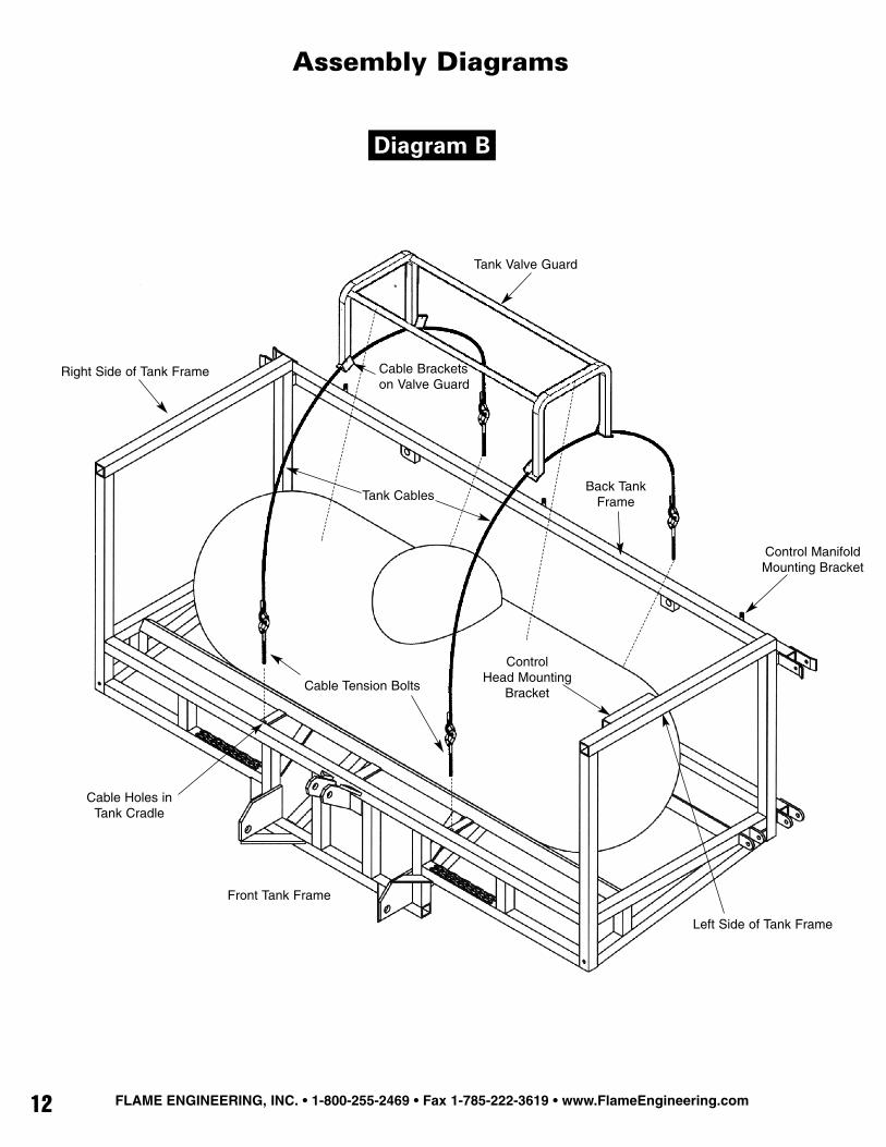
Parts List For 6 Row Unit Control Head C-16 WPNo. Part No. Description1. S-714 1/2” Fuel Strainer2. 1/2” Hex Nipple3. S-122 12 Volt 1/2” Solenoid4. H-1004 1/2” x 5’ Fuel Supply Line (Male x Female Swivel) 5. A-408 Male Adaptor 3/8” to 1/4”6. H-400 Pressure Relief Valve7. 1/2” St. Tee8. 1/2” Male x 1/4” Female Reducer9. R-1584H Regulator10. V-334 By Pass Valve11. MB-6 Brass Manifold Block 1/4”12. G-25 Pressure Gauge13. 3/8” Female x 1/4” Female Brass Reducer14. HP-1S 1 Ft. LPG Hose 1/4”15. 1/2” Male x 3/8” Male Flare x 3/8” Male Flare Tee16. HP384S 4 Ft. LPG Hose 3/8”17. 1/4” Allen Head Plug18. 1/2”Male x 1/2” Male Flare 90° Elbow19. 1/2” x 8 1/2” Nipple with 3/8 x 1” Bolt (2)20. 1/4” x 3” Nipple with 3/8 x 1” Bolt21. HP3810TS 10 Ft. LPG Hose 3/8”22. M102 1/4” Brass Cross23. K-7 Control Head Mounting Bracket24. 1/2” Male x 1/2” Female Extension
6 Row Unit
1
2
3
3
4
6
7 7 7
8 8 810
15
16
21 20
20 11
13 22
175
14
9
12
18
19
C-16 WP
23
23
24

FLAME ENGINEERING, INC. • 1-800-255-2469 • Fax 1-785-222-3619 • www.FlameEngineering.com18
Control Head Assembly Diagrams
Parts List For 8 Row Unit Control Head C-18 WPNo. Part No. Description1. S-714 1/2” Fuel Strainer2. 1/2” Hex Nipple3. S-122 12 Volt 1/2” Solenoid4. H-1004 1/2” x 5’ Fuel Supply Line (Male x Female Swivel) 5. A-408 Male Adaptor 3/8” to 1/4”6. H-400 Pressure Relief Valve7. 1/2” St. Tee8. 1/2” Male x 1/4” Female Reducer9. R-1584H Regulator10. V-334 By Pass Valve11. MB-6 Brass Manifold Block 1/4”12. G-25 Pressure Gauge13. 3/8” Female x 1/4” Female Brass Reducer
8 Row Unit
1
2
3
3
4
6
7 7 7
8 8 8
10
15
16
21 20
20 11
13 11
175
14
918
19
C-18 WP
14. HP-1S 1 Ft. LPG Hose 1/4”15. 1/2” Male x 3/8” Male Flare x 3/8” Male Flare Tee16. HP384S 4 Ft. LPG Hose 3/8”17. 1/4” Allen Head Plug18. 1/2”Male x 1/2” Male Flare 90° Elbow19. 1/2” x 8 1/2” Nipple with 3/8 x 1” Bolt (2)20. 1/4” x 3” Nipple with 3/8 x 1” Bolt21. HP3810TS 10 Ft. LPG Hose 3/8”22. K-7 Control Head Mounting Bracket23. 1/2” Male x 1/2” Female Extension
23
22
22
12
FLAME ENGINEERING, INC. • 1-800-255-2469 • Fax 1-785-222-3619 • www.FlameEngineering.com 19
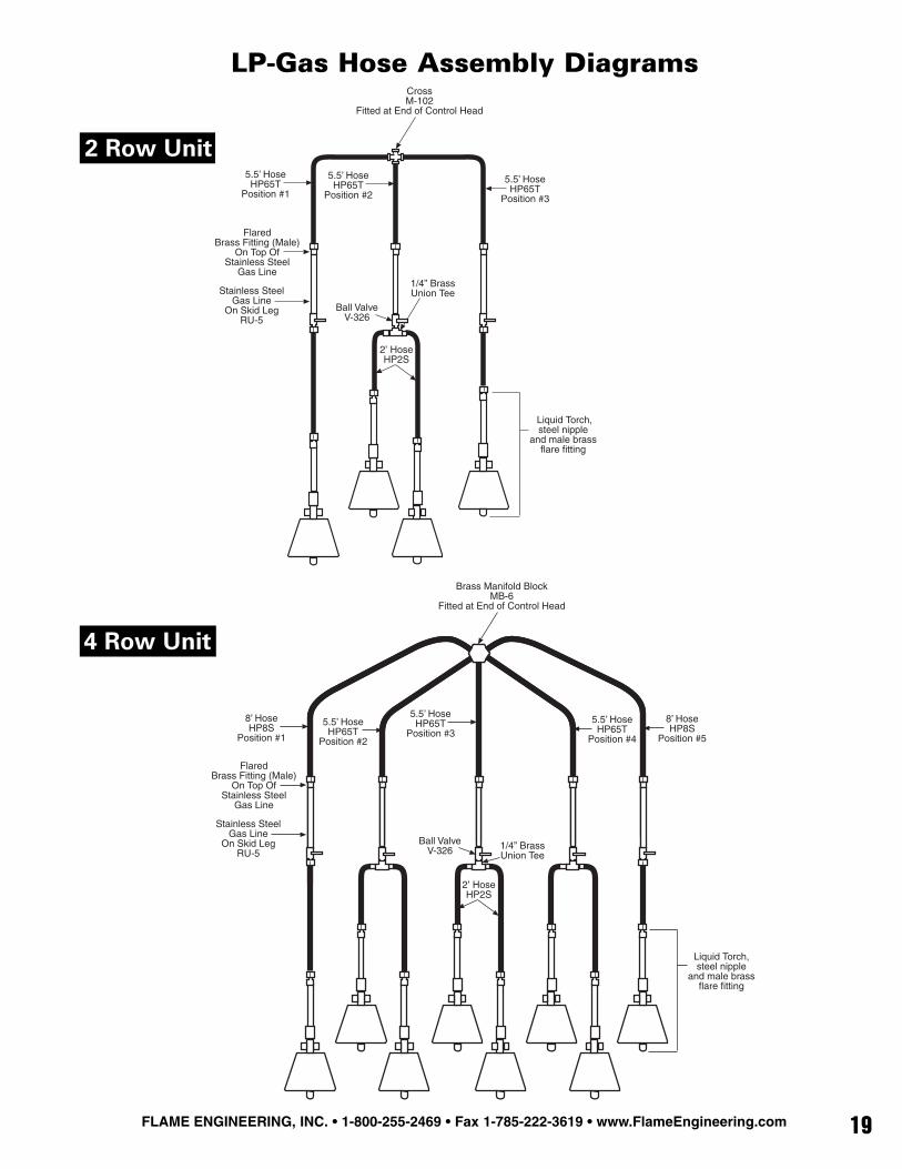
LP-Gas Hose Assembly DiagramsCrossM-102
Fitted at End of Control Head
2’ HoseHP2S
1/4” BrassUnion Tee
Liquid Torch,steel nipple
and male brassflare fitting
Ball ValveV-326
5.5’ HoseHP65T
Position #1
5.5’ HoseHP65T
Position #2
5.5’ HoseHP65T
Position #3
Stainless SteelGas Line
On Skid LegRU-5
FlaredBrass Fitting (Male)
On Top OfStainless Steel
Gas Line
Brass Manifold BlockMB-6
Fitted at End of Control Head
2’ HoseHP2S
8’ HoseHP8S
Position #1
5.5’ HoseHP65T
Position #3
8’ HoseHP8S
Position #5
1/4” BrassUnion Tee
5.5’ HoseHP65T
Position #2
5.5’ HoseHP65T
Position #4
Ball ValveV-326
Stainless SteelGas Line
On Skid LegRU-5
FlaredBrass Fitting (Male)
On Top OfStainless Steel
Gas Line
Liquid Torch,steel nipple
and male brassflare fitting
2 Row Unit
4 Row Unit

FLAME ENGINEERING, INC. • 1-800-255-2469 • Fax 1-785-222-3619 • www.FlameEngineering.com20
LP-Gas Hose Assembly Diagrams
2’ HoseHP2S
1/4” BrassUnion Tee
1/4” PlugM-109 AL
Position #3
Brass Manifold BlockMB-6
Fitted at End of Left Control Head
CrossM-102
Fitted at End of Right Control Head
8’ HoseHP8S
Position #1
8’ HoseHP8S
Position #2
5.5’ HoseHP65T
Position #45.5’ HoseHP65T
Position #5
5.5’ HoseHP65T
Position #6
5.5’ HoseHP65T
Position #7
8’ HoseHP8S
Position #8
Ball ValveV-326
Liquid Torch,steel nipple
and male brassflare fitting
Stainless SteelGas Line
On Skid LegRU-5
FlaredBrass Fitting (Male)
On Top OfStainless Steel
Gas Line
6 Row Unit

FLAME ENGINEERING, INC. • 1-800-255-2469 • Fax 1-785-222-3619 • www.FlameEngineering.com 21
LP-Gas Hose Assembly Diagrams
8 Row Unit

FLAME ENGINEERING, INC. • 1-800-255-2469 • Fax 1-785-222-3619 • www.FlameEngineering.com22
Control Switch Assembly Drawing
AlligatorClips
Control Box Indicator Light
Master Switch
SJO 16/2 Wiring15’ Long
Pilot/Main FlameSwitch
Trailer ConnectorSet
SJO 16/3 Wiring25’ Long

FLAME ENGINEERING, INC. • 1-800-255-2469 • Fax 1-785-222-3619 • www.FlameEngineering.com 23
Crop Flaming Recommendations Chart
Crop Torch Speed Torch Configuration Torch ModelPressure
Corn (2-16 in.)Small Weeds (0-2 in.) 25-30 psi 3-6 m.p.h. Staggered Cross Fire LT 1 1/2X6 or LT 1 1/2X8-DMedium Weeds (2-4 in.) 25-35 psi 3-5 m.p.h. Staggered Cross Fire LT 1 1/2X6 or LT 1 1/2X8-DLarge Weeds (4 in. +) 25-70 psi 3-5 m.p.h. Staggered Cross Fire LT 1 1/2X8-D or LT 2X8
Cotton (4-8 in.) Flaming Cotton 0-4 inches tall is not recommendedSmall Weeds (0-2 in.) 25-30 psi 3-6 m.p.h. Staggered Cross Fire LT 1 1/2X6 or LT 1 1/2X8-DMedium Weeds (2-4 in.) 25-35 psi 3-5 m.p.h. Staggered Cross Fire LT 1 1/2X6 or LT 1 1/2X8-DLarge Weeds (4 in. +) 25-40 psi 3-5 m.p.h. Staggered Cross Fire LT 1 1/2X6 or LT 1 1/2X8-D
Soybeans (10-12 inches) Flaming Soybeans 0-10 inches tall is not recommendedSmall Weeds (0-2 in.) 20-30 psi 3-6 m.p.h. Staggered Cross Fire LT 1 1/2X6 or LT 1 1/2X8-DMedium Weeds (2-4 in.) 25-35 psi 3-5 m.p.h. Staggered Cross Fire LT 1 1/2X6 or LT 1 1/2X8-DLarge Weeds (4 in. +) 25-40 psi 3-5 m.p.h. Staggered Cross Fire LT 1 1/2X8-D or LT 2X8
Potatoes (emerging to 8 in.)Small Weeds (0-2 in.) 20-30 psi 3-6 m.p.h. Staggered Cross Fire LT 1 1/2X6 or LT 1 1/2X8-DMedium Weeds (2-4 in.) 25-35 psi 3-5 m.p.h. Staggered Cross Fire LT 1 1/2X6 or LT 1 1/2X8-DLarge Weeds (4 in. +) 25-70 psi 3-5 m.p.h. Staggered Cross Fire LT 1 1/2X8-D or LT 2X8
Sorghum (8+ inches) Flaming Sorghum 0-4 inches is not recommendedSmall Weeds (0-2 in.) 20-30 psi 3-6 m.p.h. Staggered Cross Fire LT 1 1/2X6 or LT 1 1/2X8-DMedium Weeds (2-4 in.) 25-35 psi 3-5 m.p.h. Staggered Cross Fire LT 1 1/2X6 or LT 1 1/2X8-DLarge Weeds (4 in. +) 25-40 psi 3-5 m.p.h. Staggered Cross Fire LT 1 1/2X8-D or LT 2X8
Tomatoes (8 weeks old)Small Weeds (0-2 in.) 25-30 psi 3-5 m.p.h. Staggered Cross Fire LT 1 1/2X6 or LT 1 1/2X8-D
Broccoli (8 weeks old)Small Weeds (0-2 in.) 25-30 psi 3-5 m.p.h. Staggered Cross Fire LT 1 1/2X6 or LT 1 1/2X8-D
Cabbage (8 weeks old)Small Weeds (0-2 in.) 25-30 psi 3-5 m.p.h. Staggered Cross Fire LT 1 1/2X6 or LT 1 1/2X8-D
Burners are set so the flame goes through the row.
Initially, set the burner at an angel of 30-45° horizontal with the burners 4-10” from the crop.
Cross flaming allows the most effective coverage when targeting weeds and grasses in the row.

FLAME ENGINEERING, INC. • 1-800-255-2469 • Fax 1-785-222-3619 • www.FlameEngineering.com24
Proper Purging Of LP-Gas Container
The Importance of Purging
A very important step which must not be overlooked by LP-Gas distributors is the importance of properlypurging new LP-Gas containers. Attention to this important procedure will promote customer satisfactionand greatly reduce service calls on new installations. Consider the following:
• Both ASME and DOT specifications require hydrostatic testing of vessels after fabrication. This is usually done with water.
• Before charging with propane, the vessel will contain the normal amount of air.
Both Water and Air are Contaminants
They seriously interfere with proper operation of the system and the connected appliances. If not removed,they will result in costly service calls and needless expense far exceeding the nominal cost of proper purging.
Neutralizing Moisture
Even if a careful inspection (using a pen flashlight) reveals no visible moisture,the container must still beneutralized, since dew may have formed on the walls; additionally, the contained air may have relativehumidity up to 100%.
IMPORTANT - If a tank is allowed to run completely out, alcohol must be added when refilled. Propaneis -44° F. If the ambient air temperature is higher, there will be a thermal transfer of latent heat, hot tocold, until the temperature equalizes. This will cause icing in the system if not neutralized with methanol.
A rule of thumb for neutralizing moisture in an ASME container calls for at least 1 pint of genuine absolute anhydrous methanol* (99.85% pure) for each 100 gallons of water capacity of the container. On this basis, the minimum volumes (US measurements)for typical containers would be as shown to the right:
IMPORTANT - Avoid substitutes - they will not work. The secret of the effectiveness of methanol overall other alcohols is its high affinity for water plus a boiling point lower than all other alcohols, and mostimportant: a boiling point lower than water.
The Importance of Purging Air
If the natural volume of atmosphere in the vessel is not removed before the first fill, these problems willresult:
• Installations made in the spring and summer will experience excessive and false container pressures. This will cause the safety relief valve to open, blowing off the excess pressure.
• The air mixture present in the vapor space will be carried to the appliances. This may result in as many as 5 or more service calls from pilot light extinguishment.
• If a vapor return equalizing hose is not used, the contained air will be compressed above the liquid level,resulting in slow filling.
• If a vapor equalizing hose is used, the air and any moisture it contains, will be transferred from the stoage tank to transport.
Container Type Minimum Volume Methanol Required
100 LB ICC Cylinder 1/8 pt. (2 fl. oz.)
500 gal. tank 5 pts. (2-1/2 qts.)
1000 gal. tank 10 pts. (1-1/4 gal.)
2000 gal. tank 20 pts. (2-1/2 gal.)
FLAME ENGINEERING, INC. • 1-800-255-2469 • Fax 1-785-222-3619 • www.FlameEngineering.com 25
Additionally, if atmospheric air is properly purged from the storage tank;
• transfer will be faster,• the pump will not stall,• less energy will be required to fill the container.
Never Purge With Liquid
The wrong way of course is the easiest way. Never purge a container with liquid propane. To do so causesthe liquid to flash into vapor, chilling the container, and condensing any moisture vapor on the walls whereit remains while the pressure is being blown down. Additionally, less than 50% or as little as 25% of the airwill be removed by this easy but wrong method.
Proper Purging of LP-Gas Container Cont.

FLAME ENGINEERING, INC. • 1-800-255-2469 • Fax 1-785-222-3619 • www.FlameEngineering.com26
Vacuum Pre-Purged Domestic Tanks
Read This Before Initial LP-Gas Filling of a Vacuum Pre-Purged Domestic TankThis new container has been vacuum purged of air in accordance with the NPGA Safety Bulletin #133-89(a). The service valve, vapor return valve and the fill valve have been equipped with tamper evident sealsto indicate if the valve(s) have been opened. If the tamper evident seals have been violated, THE CON-TAINER MUST BE REPURGED in accordance with NPGA Safety Bulletin #133-89 (a). (See ProperPurging)
Failure to properly purge a container can result in increased pressure, improper burning fuel mixture andodorant fade. Any of these conditions can result in personal injury, property damage or death.
Vacuum Verification Process:
To verify that a vacuum is present, remove the plastic wrap from the service valve, verify that the servicevalve hand wheel is close. Connect a vacuum pressure gauge to the service valve outlet connection andopen the hand wheel. Visually check the vacuum pressure gauge dial for the presence of a vacuum. Closethe service valve and disconnect the vacuum gauge. if the vacuum is not in accordance with NPGA SafetyBulletin #133-89 (a), THE CONTAINER MUST BE REPURGED.
Methanol Injection Process:
Inject methanol into the container through the service valve (before filling the conainer with LP-Gas) usingthe service valve outlet connection. Attach the POL connection to the service outlet connection. The POLconnection should have a low pressure rubber hose extend into a container of methanol.
Slowly open the service valve to allow the vacuum in the vessel to pull the methanol into the vessel. The container of methanol should NOT be allowed to run dry and pull air into the vessel.
• The presence of a vacuum in the container does not eliminate the need for the introduction of methanol into the container.
• The rule of thumb for neutralizing moisture in an ASME container is to introduce at least one pint of gen-uine absolute anhydrous methanol (99.85% pure) for each 100 gallon of water capacity of the container.
LP-Gas Injection Process:
After the completion of the methanol injection process, connect a hose from a source of LPG to the POLconnection of the service valve. This hose can be used to inject either liquid or vapor product into the ves-sel. The appropriate amount of LPG to neutralize the vacuum pressure in the container will vary dependingon the volume of the vessel. If liquid is used, 1 to 4 gallons of LPG is required for all vessels up to 1000wg. If vapor is used, wait until there is no longer an audible transfer of vapor from the source of the LPGto the vessel.
Filling Process:
After the completion of the LP-Gas injection process, close the service valve and disconnect the POL con-nection. Remove the plastic wrap from the filler connection, remove the yellow cap and connect your fillerhose to the vessel and proceed to fill in the normal manner.

FLAME ENGINEERING, INC. • 1-800-255-2469 • Fax 1-785-222-3619 • www.FlameEngineering.com 27
If You Have Questions
Trouble Shooting Tips(Read This First Before Calling the Factory)
Installation Problems:If you have problems, questions, or feel you are missing a part during installation, please call Flame Engineering toll free at 1-800-255-2469 and our trained staff will gladly help you.
Operation Problems:If you have problems during operation, please check the following trouble shooting guidelines first. If you use this guide and still have problems call Flame Engineering and our staff will try to help remedythe situation.
START WITH A NEW CLEAN TANKAlways begin with a clean, purged, liquid tank, capable of delivering liquid to the torches. DO NOT use a vapor withdrawal tank. Use clean fuel to avoid line/torch blockage.
IF YOU EXPERIENCE FLAME OUTCheck the fuel strainer if you are experiencing flame out. Clean accordingly. If tank debris is found in strainer or torches shortly after use, begin again with a new, clean, scrubbed and purged tank. (See Your LP-Gas Dealer) Have you aded methonal? (1 pt per hundred gal) If your tank runs out of propane, a thermal transfer of latent heat will occur. heat transfers from hot to cold. Inside the tank it is-44°, outside ambient air is much higher, so warm moist air will transfer until temperature is equalized.You can also get moisure from the bulk tank hose or tank. it is recommended that whenever ther is a flow problem, add methonal. Adding methanol every 3-4 tanks is a good plan.
IF YOU ARE GETTING A LOW FLAMECheck torch orifices for blockage. Clean thoroughly if necessary.
IF YOU HAVE AN OLD TANKOlder tanks may require cleaning as mentioned above. Through time, debris settles at bottom of the tank, where liquid is to be withdrawn through the wet leg and can cause blockage to torches. See your LP-Gas dealer for suggestions.
IF NO FUEL IS GETTING THROUGH TO THE TORCHESCheck electrical connections to the battery, then solenoids and make certain all valves are free and clear of tank debris.
FLAME ENGINEERING, INC. • 1-800-255-2469 • Fax 1-785-222-3619 • www.FlameEngineering.com
FLAME ENGINEERING, INC. 230 West Highway 4 • P.O. Box 577
LaCrosse, Kansas 67548Toll Free 1-800-255-2469 • 1-785-222-2873
Fax 1-785-222-3169 • www.FlameEngineering.com
®
RUINST3-2011