Rectangular Patch Array Antenna with Liquid Crystal ... Patch Array Antenna with Liquid Crystal...
6
Rectangular Patch Array Antenna with Liquid Crystal Substrate for Ka and Q Band Applications I.Govardhani 1 1.Associate Professor, Department of ECE, K L University [email protected] M.Venkata Narayana 2 2.Associate Professor, Department of ECE, K L University [email protected] Abstract: This paper mainly deals with the design of Microstrip rectangular patch array antenna on liquid crystal substrate at 40GHz. The antenna parameters are simulated using commercial Ansoft HFSS software and the detailed explanation of performance evaluation is presented. A 4x4 rectangular patch array was designed on liquid crystal substrate material and their return loss, input impedance, gain and antenna parameters are studied and presented in this paper. Keyword: Liquid crystal substrate, phased array antenna, micro strip 1 Introduction. Micro strip patch antenna consists of a radiating patch on one side of a dielectric substrate, which has a ground plane on the other side. A Micro strip patch antenna/patch antenna is a narrowband, wide-beam antenna fabricated by etching the antenna element pattern in metal trace bonded to an insulating dielectric substrate with a continuous metal layer bonded to the opposite side of the substrate which forms a ground plane. 2 Antenna Model. Fig:1:antenna model 3 Antenna Design considerations. A 4X4 rectangular patch array antenna with liquid crystal substrate has been designed and simulated at 40GHz frequency in this paper. We have taken liquid crystal dielectric constant (Єr) as 3 and loss tangent (δ) as 0.003. If „L‟ is the resonant length of patch, normally width (W) should be larger than L so that large bandwidth can be obtained. Here we have taken width (W) as 1.5 times of length (L). Height of the dielectric substrate should be in between 0.003 λ0 and 0.05λ0. We have taken 0.02 times of λ0. As 50Ω coaxial cables are used normally, feed point is taken where 50Ω resistance occurs. 4 Patch Model. Fig:2:patch model 5 Liquid crystal substrate. Liquid Crystal Polymer (LCP) is a fairly new and promising thermoplastic organic material. It can be used as a low-cost dielectric material for high-volume large-area processing methods that provide very reliable high-performance circuits at low cost. It has impressive electrical characteristics, which is indirectly related to its low and stable water absorption rate (<0.04%). It has a nearly constant dielectric constant Govardhani et al, International Journal of Computer Science & Communication Networks,Vol 2(1), 16-21 16 ISSN:2249-5789
Transcript of Rectangular Patch Array Antenna with Liquid Crystal ... Patch Array Antenna with Liquid Crystal...
Rectangular Patch Array Antenna with Liquid Crystal
Substrate for Ka and Q Band Applications
I.Govardhani1
1.Associate Professor, Department of ECE, K
L University
M.Venkata Narayana2
2.Associate Professor, Department of ECE, K
L University
Abstract:
This paper mainly deals with the design of
Microstrip rectangular patch array antenna on liquid
crystal substrate at 40GHz. The antenna parameters
are simulated using commercial Ansoft HFSS software
and the detailed explanation of performance
evaluation is presented. A 4x4 rectangular patch array
was designed on liquid crystal substrate material and
their return loss, input impedance, gain and antenna
parameters are studied and presented in this paper.
Keyword: Liquid crystal substrate, phased array
antenna, micro strip
1 Introduction.
Micro strip patch antenna consists of a
radiating patch on one side of a dielectric substrate,
which has a ground plane on the other side. A Micro
strip patch antenna/patch antenna is a narrowband,
wide-beam antenna fabricated by etching the antenna
element pattern in metal trace bonded to an insulating
dielectric substrate with a continuous metal layer
bonded to the opposite side of the substrate which
forms a ground plane.
2 Antenna Model.
Fig:1:antenna model
3 Antenna Design considerations.
A 4X4 rectangular patch array antenna with liquid
crystal substrate has been designed and simulated at
40GHz frequency in this paper. We have taken liquid
crystal dielectric constant (Єr) as 3 and loss tangent (δ)
as 0.003. If „L‟ is the resonant length of patch,
normally width (W) should be larger than L so that
large bandwidth can be obtained. Here we have taken
width (W) as 1.5 times of length (L). Height of the
dielectric substrate should be in between 0.003 λ0 and
0.05λ0. We have taken 0.02 times of λ0. As 50Ω
coaxial cables are used normally, feed point is taken
where 50Ω resistance occurs.
4 Patch Model.
Fig:2:patch model
5 Liquid crystal substrate.
Liquid Crystal Polymer (LCP) is a fairly new
and promising thermoplastic organic material. It can be
used as a low-cost dielectric material for high-volume
large-area processing methods that provide very
reliable high-performance circuits at low cost. It has
impressive electrical characteristics, which is indirectly
related to its low and stable water absorption rate
(<0.04%). It has a nearly constant dielectric constant
Govardhani et al, International Journal of Computer Science & Communication Networks,Vol 2(1), 16-21
16
ISSN:2249-5789
of 3 over the entire RF range up to 110 GHz. In
addition, LCP has a very low loss tangent of only
0.002, which increases to only 0.0045 at 110GHz,
thereby making LCP very suitable in designing mm-
wave applications. LCP is flexible, recyclable,
impervious to most chemicals, and it is stable up to its
high melting temperature making LCP an ideal choice
for circuits operating in all kinds of environments.
6 Simulation &Analysis.
The designed antenna is simulated using
HFSS software. The results obtained are mentioned
below.
6.1 Return loss Curve.
Fig:3:return loss
A return loss of -17.76dB is obtained at 52.5GHz
6.2Gain.
The ratio of the intensity, in a given direction, to the
radiation intensity that would be obtained if the power
accepted by the antenna were radiated isotropically.
6.2.1 3-D Gain.
Fig:4:3D gain
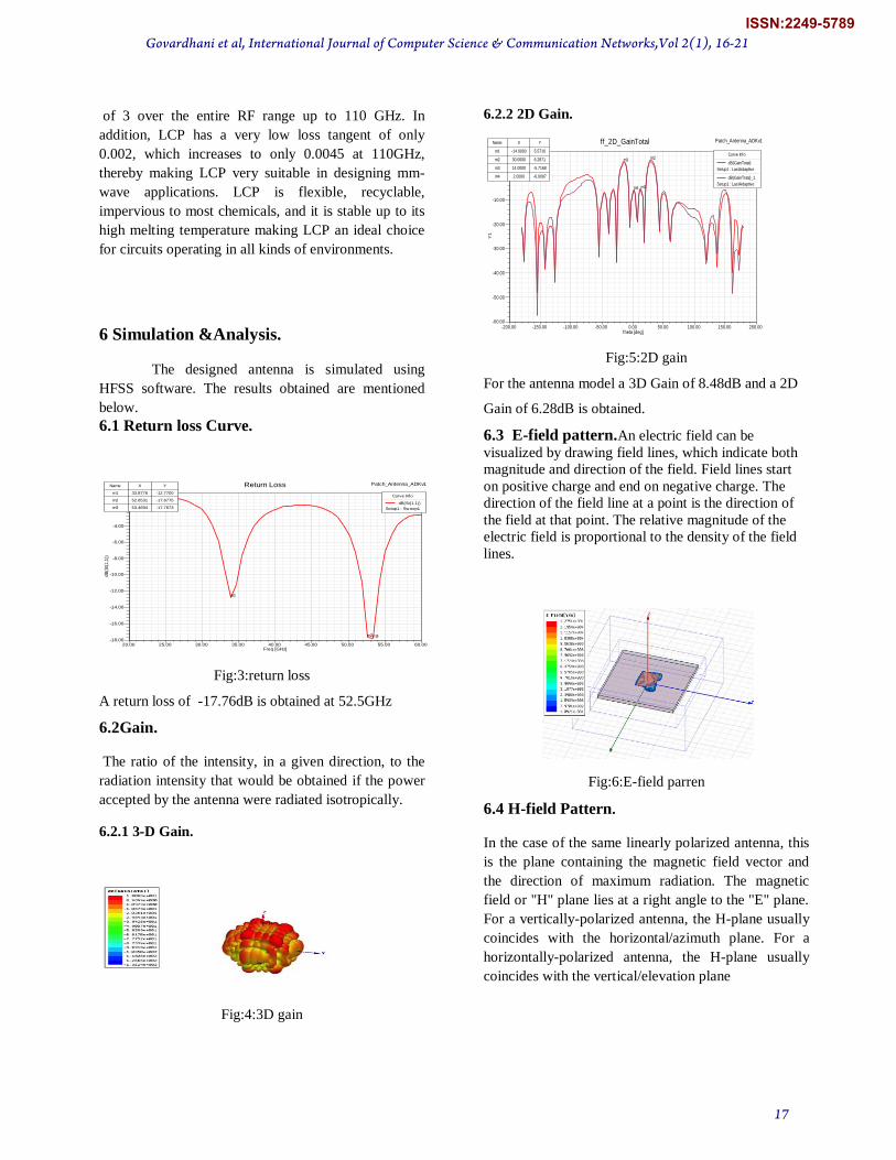
6.2.2 2D Gain.
Fig:5:2D gain
For the antenna model a 3D Gain of 8.48dB and a 2D
Gain of 6.28dB is obtained.
6.3 E-field pattern.An electric field can be
visualized by drawing field lines, which indicate both
magnitude and direction of the field. Field lines start
on positive charge and end on negative charge. The
direction of the field line at a point is the direction of
the field at that point. The relative magnitude of the
electric field is proportional to the density of the field
lines.
Fig:6:E-field parren
6.4 H-field Pattern.
In the case of the same linearly polarized antenna, this
is the plane containing the magnetic field vector and
the direction of maximum radiation. The magnetic
field or "H" plane lies at a right angle to the "E" plane.
For a vertically-polarized antenna, the H-plane usually
coincides with the horizontal/azimuth plane. For a
horizontally-polarized antenna, the H-plane usually
coincides with the vertical/elevation plane
20.00 25.00 30.00 35.00 40.00 45.00 50.00 55.00 60.00Freq [GHz]
-18.00
-16.00
-14.00
-12.00
-10.00
-8.00
-6.00
-4.00
-2.00
0.00
dB
(St(
1,1
))
Ansoft Corporation Patch_Antenna_ADKv1Return Loss
m1
m2m3
Curve Info
dB(St(1,1))
Setup1 : Sw eep1
Name X Y
m1 33.8776 -12.7700
m2 52.6531 -17.6775
m3 53.4694 -17.7673
-200.00 -150.00 -100.00 -50.00 0.00 50.00 100.00 150.00 200.00Theta [deg]
-60.00
-50.00
-40.00
-30.00
-20.00
-10.00
0.00
10.00
Y1
Ansoft Corporation Patch_Antenna_ADKv1ff_2D_GainTotal
m1 m2
m3m4
Curve Info
dB(GainTotal)
Setup1 : LastAdaptive
dB(GainTotal)_1
Setup1 : LastAdaptive
Name X Y
m1 -14.0000 5.5710
m2 30.0000 6.2871
m3 14.0000 -5.7168
m4 2.0000 -6.0097
Govardhani et al, International Journal of Computer Science & Communication Networks,Vol 2(1), 16-21
17
ISSN:2249-5789
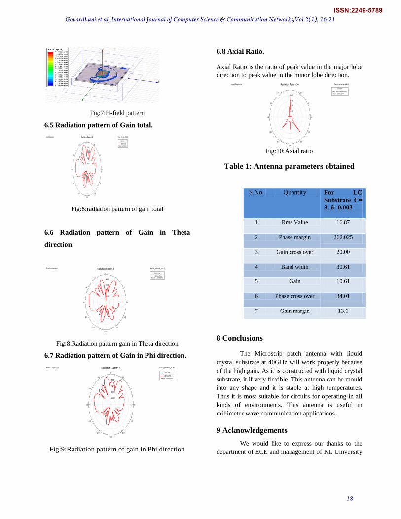
Fig:7:H-field pattern
6.5 Radiation pattern of Gain total.
Fig:8:radiation pattern of gain total
6.6 Radiation pattern of Gain in Theta
direction.
Fig:8:Radiation pattern gain in Theta direction
6.7 Radiation pattern of Gain in Phi direction.
Fig:9:Radiation pattern of gain in Phi direction
6.8 Axial Ratio.
Axial Ratio is the ratio of peak value in the major lobe
direction to peak value in the minor lobe direction.
Fig:10:Axial ratio
Table 1: Antenna parameters obtained
S.No. Quantity For LC
Substrate Є=
3, δ=0.003
1 Rms Value 16.87
2 Phase margin 262.025
3 Gain cross over 20.00
4 Band width 30.61
5 Gain 10.61
6 Phase cross over 34.01
7 Gain margin 13.6
8 Conclusions
The Microstrip patch antenna with liquid
crystal substrate at 40GHz will work properly because
of the high gain. As it is constructed with liquid crystal
substrate, it if very flexible. This antenna can be mould
into any shape and it is stable at high temperatures.
Thus it is most suitable for circuits for operating in all
kinds of environments. This antenna is useful in
millimeter wave communication applications.
9 Acknowledgements
We would like to express our thanks to the
department of ECE and management of KL University
-38.00
-26.00
-14.00
-2.00
90
60
30
0
-30
-60
-90
-120
-150
-180
150
120
Ansoft Corporation Patch_Antenna_ADKv1Radiation Pattern 9
Curve Info
dB(GainTotal)
Setup1 : LastAdaptive
-46.00
-32.00
-18.00
-4.00
90
60
30
0
-30
-60
-90
-120
-150
-180
150
120
Ansoft Corporation Patch_Antenna_ADKv1Radiation Pattern 8
Curve Info
dB(GainTheta)
Setup1 : LastAdaptive
-46.00
-32.00
-18.00
-4.00
90
60
30
0
-30
-60
-90
-120
-150
-180
150
120
Ansoft Corporation Patch_Antenna_ADKv1Radiation Pattern 7
Curve Info
dB(GainPhi)
Setup1 : LastAdaptive
12.00
24.00
36.00
48.00
90
60
30
0
-30
-60
-90
-120
-150
-180
150
120
Ansoft Corporation Patch_Antenna_ADKv1Radiation Pattern 10
Curve Info
dB(AxialRatioValue)
Setup1 : LastAdaptive
Govardhani et al, International Journal of Computer Science & Communication Networks,Vol 2(1), 16-21
18
ISSN:2249-5789
for their continuous support and encouragement during
this work.
10 References:
[1] Microstrip Antennas: The Analysis and Design of Microstrip Antennas and Arrays, David M. Pozar and Daniel H. Schaubert, Editors, Wiley/IEEE Press, 1995. [2] Constantine A. Balanis; Antenna Theory, Analysis and Design, John Wiley & Sons Inc. 2ndedition. 1997. [3]Comparative Analysis of Exponentially Shaped Microstrip-Fed Planar Monopole Antenna With and Without Notch M. Venkata Narayana1, I.Govadhani2, K.P.Sai Kumar, K. Pushpa Rupavathi [4] Liquid Crystal Polymer (LCP): The Ultimate Solution for Low Cost RF Flexible Electronics and Antennas, Rushi Vyas, Amin Rida, Swapan Bhattacharya and Manos M. Tentzeris, IEEE 2007. [5]M A Matin, M.P Saha, H. M. Hasan “Design of Broadband Patch Antenna for WiMAX and WLAN” ICMMT 2010 Proceedings, pp. 1-3 [6] F. Yang, X. X. Zhang, X. Ye, and Y. Rahmat-Samii, “Wide-band Eshaped patch antennas for wireless communications,” IEEE Trans. Antennas Propag., vol. 49, no. 7, pp. 1094–1100, Jul. 2001. [7]M. Sanad, “Double C-patch antennas having different aperture shapes,” in Proc. IEEE AP-S Symp., Newport Beach, CA, Jun. 1995, pp. 2116–2119. [8] Shackelford, A.K., Lee, K.F., and Luk, K.M.: „Design of small-size widebandwidth microstrip-patch antennas‟, IEEE Antennas Propag. Mag., 2003, AP-45, (1), pp. 75–83 [9] H. F. AbuTarboush, H. S. Al-Raweshidy, and R. Nilavalan, “Triple band double U-slots patch antenna for WiMAx mobile applications,” in Proc. Of APCC, Tokyo, Feb. 2008, pp. 1-3. [10]Waterhouse, R.B.: „Broadband stacked shorted patch‟, Electron. Lett. 1999, 35, (2), pp. 98–100 [11] Guo, Y.X., Luk, K.M., and Lee, K.F.: „L-probe proximity-fed shortcircuited patch antennas‟, Electron. Lett., 1999, 35, (24), pp. 2069–2070 [12]K.L. Lau and K.M. Luk ” Wideband folded L-slot shorted-patch Antenna” ELECTRONICS LETTERS 29th September 2005 Vol. 41 No. 20 [13]Madhur Deo Upadhayay1, A.Basu2, S.K.Koul3 and Mahesh P. Abegaonkar4,”Dual Port ASA for Frequency Switchable Active Antenna” 978-1-4244-2802-1/09/$25.00 ©2009 IEEE, pp.2722-2725 [14] R.Chair, K.F. Lee,K.M.Luk “Bandwidth and cross-polarisation characteristics of quarter wave shorted patch antenna” microwave and op.technol.Latt,vol-22 no 2,pp.101-103,1999 [15]N. Zhang, P. Li, B. Liu, X.W. Shi and Y.J. Wang “Dual-band and low cross-polarisation printed dipole antenna with L-slot and tapered structure for WLAN applications” ELECTRONICS LETTERS 17th March 2011 Vol. 47 No. 6 [16]Xue-jie Liaa, Hang-chun Yang and Na Han “AN IMPROVED DUAL BAND-NOTCHED UWB ANTENNA WITH A PARASITIC STRIP AND A
DEFECTED GROUND PLANE” 2010 International Symposium on Intelligent Signal Processing and Communication Systems (lSPACS 2010) December 6-8,2010, 978-1-4244-7371-7/10/$26.00 ©2010 IEEE [17] Hsing-Yi Chen and Yu Tao “Performance Improvement of a U-Slot Patch Antenna Using a Dual-Band Frequency Selective Surface With Modified Jerusalem Cross Elements” IEEE TRANSACTIONS ON ANTENNAS AND PROPAGATION, VOL. 59, NO. 9, SEPTEMBER 2011,pp 3482-3486 [18]Hsing-Yi Chen and Yu Tao “Antenna Gain and Bandwidth Enhancement Using Frequency Selective Surface with Double Rectangular Ring Elements” 978-1-4244-6908-6/10/201 0 IEEE, pp. 271-274 [19]S. Pinhas and S. Shtrikman, “Comparison between computed and measured bandwidth of quarter-wave microstrip radiators,” IEEE Trans.Antennas Propag., vol. 36, no. 11, pp. 1615–1616, 1988. [20] R. Waterhouse, “Small microstrip patch antenna,” Electron. Lett., vol. 31, no. 8, pp. 604–605, 1995. [21] J. R. Games, A. J. Schuler, and R. F. Binham, “Reduction of antenna dimensions by dielectric loading,” Electron. Lett., vol. 10, pp. 263–265, 1974. [22] K. L. Wong and K. P. Yang, “Compact dual-frequency microstrip antenna with a pair of bent slots,” Electron. Lett., vol. 34, no. 3, pp. 225–226, 1998. [23] K. L. Wong and Y. F. Lin, “Small broadband rectangular microstrip antenna with chip-resistor loading,” Electron. Lett., vol. 33, no. 19, pp. 1593–1594, 1997. [24]Shynu S.V. #, Maria J. Roo Ons#, Max J. Ammann#, Sarah McCormack*, Brian Norton*” Dual Band a-Si:H Solar-Slot Antenna for 2.4/5.2GHz WLAN Applications”pp.408-410 [25]Ke-Ren Chen, Chow-Yen-Desmond Sim, Member, IEEE, and Jeen-Sheen Row “A Compact Monopole Antenna for Super Wideband Applications” IEEE ANTENNAS AND WIRELESS PROPAGATION LETTERS, VOL. 10, 2011, pp. 488-491 [26]N.D. Trang, D.H. Lee and H.C. Park “ Compact printed CPW-fed monopole ultra-wideband antenna with triple subband notched characteristics “ELECTRONICS LETTERS 19th August 2010 Vol. 46 No. 17 [27]L. Y. Cai, G. Zeng, H. C. Yang“Compact Triple band Antenna for Bluetooth/WiMAX/WLAN Applications” Proceedings of International Symposium on Signals, Systems and Electronics (ISSSE2010) [28] Zhi-Qiang Li, Chang-Li Ruan “a small integrated Bluetooth and UWB antennas with WLAN band notched characteristics”, proceedings of ISSSE 2010. [29]Mohamed H. Al Sharkawy “MINIATURIZED WIDEBAND SLOTTED MONOPOLE ANTENNA FOR WLAN APPLICATIONS” (c) 2010-IEEE APS, Middle East Conference on Antennas and Propagation (MECAP),Cairo, Egypt, 20.10.2010 [30]L.Y. Cai, Y. Li, G. Zeng and H.C. Yang “Compact wideband antenna with double-fed structure having band-notched characteristics” ELECTRONICS LETTERS 11th November 2010 Vol. 46 No. 23
Govardhani et al, International Journal of Computer Science & Communication Networks,Vol 2(1), 16-21
19
ISSN:2249-5789

10. Authors Biography:
Govardhani. Immadi working as Associate
professor in KL University. Completed B.Tech in
KLCE affiliated to Acharya Nagarjuna University
in 2004. Received Masters degree from the Acharya
Nagarjuna University as a University topper in
2009.Major area of working is micro strip
antennas, electrically small antennas.
Venkata Narayana.M working as Associate
professor in KLUniversity,HODSED-1(ECE).
Completed B.Tech in 2001 in Bapatla Engineering
College affiliated to Acharya Nagarjuna University.
Received Masters Degree from the Acharya
Nagarjuna University in 2009.Major area of
working is micro strip antennas, electrically small
antennas.
Govardhani et al, International Journal of Computer Science & Communication Networks,Vol 2(1), 16-21
20
ISSN:2249-5789

Govardhani et al, International Journal of Computer Science & Communication Networks,Vol 2(1), 16-21
21
ISSN:2249-5789