Recovery Of Volatile Organic Compounds From Small …infohouse.p2ric.org/ref/43/42404.pdf ·...
66
RECOVERY FROM SMALL IN DUSTRIAL ~ ~ L ~ ~ l ~ PREVENT1 NORTH CAROLINA DEPARTMENT OF ENVIRONMENT, HEALTH, AND NATURAL RESOURCES James G. Martin Governor William W. Cobey, Jr Secretary, EHNR
Transcript of Recovery Of Volatile Organic Compounds From Small …infohouse.p2ric.org/ref/43/42404.pdf ·...

RECOVERY
FROM SMALL IN DUSTRIAL
~ ~ L ~ ~ l ~ ~ PREVENT1 NORTH CAROLINA DEPARTMENT OF ENVIRONMENT, HEALTH, AND NATURAL RESOURCES
James G. Martin Governor
William W. Cobey, Jr Secretary, EHNR


Recovery of Volatile Organic Compounds from Small
Industrial Sources
Prepared by James J. Spivey
Research Triangle Institute
Prepared for North Carolina Pollution Prevention Pays Program
Department of Natural Resmrces and Community Development

DISCLAIMER
This p r o j e c t w a s supported by t h e North Caro l ina P o l l u t i o n Prevent ion Pays Program. views and p o l i c i e s of t h e S ta te of North Carol ina, nor does mention of t r a d e names o r commercial products c o n s t i t u t e endorsement o r recommendation f o r use.
This does n o t s i g n i f y t h a t t h e con ten t s n e c e s s a r i l y r e f l e c t t h e
Copyright September 1986
North Carol ina P o l l u t i o n Prevent ion Pays Program Department of Natura l Resources and Community Development
Pos t Of f i ce Box 27687 Raleigh, Plorth Carol ina 27611-7687
(919) 733-7015
Prepared by
James J . Spivey Research Tr i ang le I n s t i t u t e
Pos t O f f i c e Box 12194 Research Tr i ang le Park, North Caro l ina 27709

THE POLLUTION PREVENTlON PROGRAM
The Pollution Prevention Program provides free technical assistance to North Carolina industries and municipalities on ways to reduce, recycle and prevent wastes before they become pollutants. This non-regulatory program, located in the Division of Environmental Management) addresses water and air quality, toxic materials, and solid and hazardous waste. Designated as the lead agency in waste reduction, the Program works in cooperation with the Solid and Hazardous Waste Management Branch and the Governor ' s Waste Management Board. The services and assistance available fall into the following categories:
Information Clearinghouse. An information data base provides access to literature sources, contacts, and case studies on waste reduction techniques for specific industries or waste streams. Information is also available through customized computer literature searches. Waste reduction reports published by the Program are also available.
Specific Information Packages. The staff can prepare facility or waste-stream-specific waste reduction reports for industries and communities. Information provided by the facility is used to identify cost-effective waste reduction options. A short report detailing these options is provided along with references, case studies, and contacts.
On-site Technical Assistance. The staff can provide comprehensive technical assistance through facility visits. During an on-site visit, detailed process and waste stream information is collected. The information is analyzed, and a series of waste reduction options are identified. A report is prepared detailing these options and includes literature, contacts, case studies, and vendor information.
Outreach. The staff can give presentations on pollution prevention to industries, trade associations, professional organizations, and citizen groups. Depending on the audience, these programs range from an overview of the State's Pollution Prevention Program to in-depth discussions of technologies for specific industries.
Challenge Grants. A matching grant program provides funds for the cost of personnel, materials, or consultants needed to undertake pollution prevention projects. Projects eligible for grant funds range from characterizing waste streams in order to identify pollution reduction techniques to conducting in-plant and pilot-scale studies of reduction technologies.
For information or technical assistance contact:
Pollution Prevention Program Division of Environmental Management N.C. Department of Natural Resources & Community Development Post Office Box 27687 Raleigh, North Carolina 27611-7687
Telephone: 919/733-7015


Table of Contents
Sect i o n
Introduction ............................................. 1.0 Process Description ......................................
1.1 Adsorption .......................................... 1.2 Absorption .......................................... 1.3 Condensation ........................................
2.0 Technical Considerations ................................. 2.1 Adsorption ..........................................
2.1 .1 Sorbents ..................................... 2.1.2
2.2 Absorption .......................................... 2.2 .1 Absorbent .................................... 2.2.2 Process Configuration ........................
2.3 Condensation ........................................
Typical Design and Performance Parameters ....
3.0 Economic Considerations .................................. 3.1 Adsorption .......................................... 3.3 Condensation ........................................ 3.2 Absorption ..........................................
4.0 Vendors .................................................. 4.1 Adsorption .......................................... 4.2 Absorption .......................................... 4.3 Condensation ........................................
5.0 Example Cases ............................................ 5.2 Absorption .......................................... 5.3 Condensation ........................................ 5 .1 Adsorption ..........................................
6.0 References ............................................... Appendix A . Vendor Worksheets for Carbon ............... Adsorption Systems .......................................
1
9 9 9
14 19 20 20 22
25 25 25 26
30 30 30 32
33 33 38 40
43
43


L i s t of Figures
Ne,
1
2
3
4
&2.&
1
2
3
4
General process f low diagram of an adsorp t ion process f o r VOC recovery . . . . . . . . . . . . . . . . . . . . . . . . . . . . . . . . .
L%s
3
General process f low diagram of a condensation process f o r VOC recovery. . . . . . . . . . . . . . . . . . . . . . . . . . . . . . . . . 6
General process f low diagram of an adsorp t ion process f o r VOC recovery . . . . . . . . . . . . . . . . . . . . . . . . . . . . . . . . . 8
General ranges of VOC concent ra t ion and gas 10 f low r a t e f o r s e l e c t e d recovery techniques. ..............
Adsorption isotherms f o r two VOCs ....................... 12
Heat Exchanger Cos ts . . . . . . . . . . . . . . . . . . . . . . . . . . . . . . . . . . . . . 27
Cost of I n d u s t r i a l Re f r ige ra t ion ......................... 27
L i s t of Tables
P r a c t i c a l Guidel ines f o r t h e Use of Act ivated Carbon f o r VOC Recovery .................................. 15
Complicating Fac tors i n Carbon Adsorption Design ......... 1 7
Advantages and Disadvantages of Various S t r ipp ing Agents ......................................... 23
Summary of Costs f o r Condensation and Fixed-Bed Carbon Adsorption ........................................ 29
5 L i s t of Vendors of Activated Carbon Systems €or VOC Recovery. ........................................ 31
6 Information t h e Buyer Must Supply ........................ 34


INTRODUCTION
This monograph descr ibes t h e t h r e e gener ic technologies--adsorpt ion,
absorp t ion , and condensat ion--avai lable f o r t h e recovery of v o l a t i l e
organic compounds ( V O C s ) from gas streams generated by small
sources . Adsorption is t h e contac t of t h e VOC-containing gas
s o l i d sorbent followed by regenera t ion of t h e spent so rben t ,
c y c l i c process . Absorption is t h e con tac t of t h e gas stream
i n d u s t r i a l
stream wi th a
u s u a l l y i n a
wi th a
nonvo la t i l e l i q u i d i n which t h e VOC is so lub le followed by regenera t ion of
t h e l i q u i d , u sua l ly cont inuously. Condensation is simply t h e cont inuous
cool ing of t h e gas stream t o condense t h e VOC d i r e c t l y .
Because it is t h e most economical way t o rermve VOCs from a wide range
of streams encountered i n t h e f i e l d , adsorp t ion is by f a r t h e most
widespread technology for VOC recovery. By choosing an appropr i a t e sorbent
and process conf igu ra t ion , many chemical types of VOCs can be recovered.
Absorption i s used where t h e VOC concent ra t ion i s r e l a t i v e l y h igh and when
an appropr i a t e inexpensive absorbent l i q u i d is a v a i l a b l e . Condensation can
be energy i n t e n s i v e and is gene ra l ly used f o r gas streams wi th h igh VOC
conten t .
T rea t ing a VOC-containing gas stream t o recover t h e V O C ( s ) i s only one
Other a l t e r n a t i v e s t h a t may be of s e v e r a l broad a l t e r n a t i v e s t o consider .
more economical inc lude process modi f ica t ions t o reduce or e l imina te t h e
VOC conten t of t h e gas s t ream and us ing an u l t i m a t e d e s t r u c t i o n technique.
A t e c h n i c a l and economic eva lua t ion of a v a i l a b l e a l t e r n a t i v e s ( recovery ,
process modi f ica t ion , or u l t ima te d e s t r u c t i o n ) is a p r e r e q u i s i t e t o making
t h e r i g h t choice f o r VOC con t ro l . I t is t h e purpose of t h i s monograph t o
d i scuss only recovery and t o provide genera l gu ide l ines f o r eva lua t ion of
t h e a v a i l a b l e recovery techniques f o r s p e c i f i c cases.
not consider VOC c o n t r o l techniques t h a t a r e p r imar i ly means of u l t i m a t e
d e s t r u c t i o n of t h e VOC, e .g. , i n c i n e r a t i o n or c a t a l y t i c ox ida t ion .
This monograph does
1

1.0 PROCESS DESCRIPTION
1.1 Bdsorption
Adsorption is t h e process of adhesion of a very t h i n l a y e r of molecules
from a gas or l i q u i d t o t h e s u r f a c e of a s o l i d a s a r e s u l t of phys i ca l o r
chemical f o r c e s between t h e s o l i d and t h e adhering molecules. For t h e
recovery of V O C s , we a r e i n t e r e s t e d exc lus ive ly i n gas-phase molecules
adsorbing on a s o l i d m a t e r i a l as a r e s u l t of phys i ca l f o r c e s a lone , which
pe rmi t s t h e adsorbed molecule t o be recovered chemical ly unchanged.
Adsorption processes are extremely f l e x i b l e f o r VOC recovery. By
choosing an appropr i a t e adsorbent ( t h e s o l i d i n t h e above d e f i n i t i o n ) and
process ing cond i t ions , a wide range of VOCs can be recovered c o s t
e f f e c t i v e l y . For t h i s reason, numerous commercially a v a i l a b l e processes
have been developed f o r t h i s purpose. For r e l a t i v e l y small i n d u s t r i a l VOC
sou rces , systems are a v a i l a b l e t h a t r e q u i r e a minimum of maintenance and
ope ra to r a t t e n t i o n . These systems a r e usua l ly p r a c t i c a l f o r small f low
r a t e s of VOC-containing gas (from s e v e r a l hundred t o t e n s of thousands of
f t3 /min ) and low VOC concen t r a t ions (usua l ly s e v e r a l hundred up t o s e v e r a l
thousand ppm) . Figure 1 is a gene ra l schematic diagram of how adso rp t ion is used f o r
VOC recovery. Although t h e s p e c i f i c d e t a i l s of con tac t ing between t h e gas
s t ream and t h e adsorbent may d i f f e r among vendors of va r ious systems, i n
p r i n c i p l e a l l c y c l i c adso rp t ion systems f o r VOC recovery can be represented
by t h e process shown." The VOC-containing gas stream is f i r s t condi t ioned
by a p a r t i c u l a t e f i l t e r and perhaps a cooler ldehumidi f ie r .
contac ted wi th a bed of t h e sorbent m a t e r i a l , u s u a l l y a f ixed bed of
granular a c t i v a t e d carbon. The VOC is p r e f e r e n t i a l l y adsorbed from t h e gas
It is t hen
*While a l l subsequent d i scuss ion of VOC recovery by adso rp t ion is based on t h e type of sys tem shown i n Figure 1, two o t h e r types of adso rp t ion VOC recovery systems a r e a v a i l a b l e . One involves adso rp t ion under p r e s s u r e wi th r egene ra t ion accomplished by p res su re reduct ion . Such "p res su re swing" systems a r e not g e n e r a l l y used f o r VOC recovery, bu t i n p r i n c i p l e could be ( see r e fe rence 1). The second involves cont inuous con tac t of t h e gas and sorbent s t r eam i n a f l u i d i z e d bed conf igu ra t ion . Such systems a r e not p r a c t i c a l f o r t h e r e l a t i v e l y low flow rates considered h e r e i n , b u t should be eva lua ted for l a r g e r flows ( s e e r e fe rence 4 , p. 7 0 1 ) .
2

.
b Y-
C m Y- O
m E
3

s t ream and t h e c l e a n gas leaves t h e sorbent bed. When t h e bed i s
exhausted, i . e . , when t h e VOC concen t r a t ion i n t h e o u t l e t gas s t ream
exceeds a maximum acceptab le l e v e l ( t h i s is c a l l e d "breakthrough") , t h e bed
is taken o f f - l i n e f o r regenera t ion and t h e VOC-containing gas s t ream is
d i v e r t e d t o a f r e s h ( regenera ted) sorbent bed. For continuous VOC removal,
t h i s impl ies t h e need f o r a t least t w o , and perhaps more, sorbent beds
ope ra t ing i n p a r a l l e l . Regeneration of t h e spent sorbent can be done on-
s i t e ( a s shown) or o f f - s i t e by t h e sorbent vendor or by a f o r - f e e
r egene ra t ion s e r v i c e .
p re s su re (-15 p s i g ) steam. Other regenera t ing gases a r e sometimes used i n
s p e c i a l cases ( s e e Sec t ion 2.1). I f steam is used, hea t r e l eased by
condensat ion of t h e steam causes t h e VOC t o desorb from t h e sorbent and t h e
The most common method of r egene ra t ion is by low-
r e s u l t i n g vapor mixture is condensed downstream of t h e sorbent bed. The
condensed l i q u i d is allowed t o s e p a r a t e i n t o two phases. The recovered VOC
is then decanted and i s a v a i l a b l e f o r re-use or s a l e . ( I n t h i s ca se , t h e
block i n F igure 1 l abe led "VOC recovery" would c o n s i s t of a condenser and
d e c a n t e r . ) The aqueous phase can then be s e n t d i r e c t l y t o wastewater
t r ea tmen t , s u b j e c t t o r e s t r i c t i o n s d iscussed i n Sec t ion 2.1.
1 .2 Absorption
Absorption i s t h e t r a n s f e r of one component of a gas mixture t o a
l i q u i d due t o p r e f e r e n t i a l s o l u b i l i t y of t h e gas i n t h e l i qu id . " For VOC
recovery, t h i s process involves t h e t r a n s f e r of t h e VOC from a gas s t r eam
t o a s u i t a b l e l i q u i d i n which t h e VOC i s so lub le .
I n p r i n c i p l e , almost a l l VOCs can be recovered from any gas mixture by
s e l e c t i o n of an appropr i a t e l i q u i d absorbent and ope ra t ing cond i t ions .
Although abso rp t ion is probably t h e most important gas-phase p o l l u t i o n
c o n t r o l ope ra t ion7 (for removal of a c i d s t a c k gases , f o r example), i t s use
f o r VOC recovery from small i n d u s t r i a l sources is not widely p rac t i ced .8
I ts r e l a t i v e l y complex ope ra t ion and t h e consequent c o s t account for i t s
l i m i t e d use .
*Absorption i s sometimes accompanied by chemical r e a c t i o n or complexation of t h e absorba te ( t h e s o l u b l e gas i n t h i s d e f i n i t i o n ) wi th , or i n , t h e absorbent . This process is not a p p l i c a b l e t o VOC recovery, however.
6

Figure 2 i s a general process f low diagram of an abso rp t ion process f o r
VOC recovery. The VOClcontaining gas stream i s f i r s t contacted
cont inuously and coun te rcu r ren t ly wi th an absorbent l i q u i d i n a column
containing e i t h e r packing o r t r a y s . The VOC absorbs i n t h e l i q u i d , which
then e x i t s t h e bottom of t h e tower, w i th t h e c l e a n gas l eav ing t h e t o p of
t h e column. The absorbent/VOC mixture is t hen contacted wi th a s t r i p p i n g
agent of some s o r t . This can be steam, a i r , o r another l i q u i d . The * purpose of t h i s s t r i p p i n g agent is t o remove t h e VOC from t h e absorbent so
t h a t t h e absorbent can be r e c i r c u l a t e d t o t h e abso rp t ion column. This
s t r i p p i n g is t h e exact oppos i t e of t h e abso rp t ion process and involves t h e
t r a n s f e r of t h e VOC from t h e absorbent t o t h e s t r i p p i n g agent .
used, h e a t t r a n s f e r occurs simultaneously and causes t h e s o l u b i l i t y of t h e
VOC i n t h e absorbent t o decrease, r e s u l t i n g i n vapor i za t ion of t h e VOC.
The s t e a m l V O C mixture is then condensed and decanted i n t h e VOC recovery
I f steam is
s e c t i o n i n Figure 2 , much as i n t h e case of carbon adso rp t ion (Sec t ion
2 .1) .
m u s t be sepa ra t ed t o recover t h e VOC. One d i r e c t way of doing t h i s is by
condensation, as discussed i n Sec t ions 1.3 and 2.3. If another l i q u i d i s
used, t h e VOC is e x t r a c t e d from t h e absorbent and m u s t be subsequent ly
recovered by d i s t i l l a t i o n o r some o t h e r ope ra t ion . Also no te t h a t t h e
s t r i p p i n g column of Figure 2 could be operated as a convent ional
d i s t i l l a t i o n column with t h e a d d i t i o n of a r e b o i l e r a t t h e bottom of t h e
column and t h a t t h e VOC could be recovered by t h i s convent ional technique.
I f a i r is used, t h e a i r / V O C mixture e x i t i n g t h e t o p of t h e column
1.3
Condensation i s t h e process of cool ing a gas t o a l i q u i d form by
t r a n s f e r of hea t . For t h e recovery of VOCs by condensation, t h i s process
involves cool ing t h e VOC-containing gas stream t o a temperature below t h e
dew p o i n t of t h e VOC and c o l l e c t i n g t h e condensed VOC d i r e c t l y as a l i q u i d .
Condensation has been used f o r VOC recovery by small i n d u s t r i a l u s e r s
because of i t s simple ope ra t ion , u s u a l l y f o r low gas f low rates.
equipment gene ra l ly involved i s a h e a t exchanger, which can be placed
d i r e c t l y a t t h e po in t of discharge and r equ i r e s l i t t l e , i f any, o p e r a t o r
a t t e n t i o n . Since cool ing water i s o f t e n t h e most r e a d i l y a v a i l a b l e coo lan t
f o r condensation, and s i n c e i t s i n l e t temperature i s normally a t o r above
The only
5

i
6

ambient temperature , VOC recovery by condensation using cool ing water is
l imi t ed t o h igh VOC concent ra t ions and h igher b o i l i n g VOCs. To recover
low-boi l ing, low-molecular-weight VOCs r equ i r e s r e f r i g e r a t e d cool ing , which
can be expensive.
Figure 3 i s a gene ra l process f low diagram of VOC recovery by
condensation. The VOC-containing gas is f i r s t f i l t e r e d t o remove any
p a r t i c u l a t e s t h a t could f o u l t h e hea t exchange s u r f a c e over time. Heat i s
removed from t h e gas by i n d i r e c t con tac t wi th t h e cooled s u r f a c e of t h e
condenser, and t h e VOC is recovered d i r e c t l y , e i t h e r by simply c o l l e c t i n g
drops a s they a r e formed, or by convent ional demis te rs or cyclones which
he lp coa lesce the VOC d r o p l e t s as they a r e formed.
7

0 0
t v) U w
S
d
I 0 0 > b rc
S m rc 0 E E a m m
8

2.0 TECHNICAL CONSIDERATIONS
Figure 4 shows approximate ranges of VOC concen t r a t ions and f low r a t e s
t o which t h e t h r e e technologies considered i n t h i s "graph can be
app l i ed .
and economic, and a r e discussed i n Sec t ions 2.0 and 3.0.
Limits of a p p l i c a t i o n of t h e s e technologies are both t e c h n i c a l
2 .1 Adsorption
To eva lua te s p e c i f i c adsorpt ion processes f o r a given VOC recovery
need, t h e sorbent i t s e l f and t h e o v e r a l l process design parameters must be
considered.
2.1.1 Sorbents
I n p r i n c i p l e , many so rben t s could be used f o r VOC recovery. These
include a c t i v a t e d carbon, molecular sieves, a c t i v a t e d alumina, and
ed i n commercial VOC recovery systems
ce for a c t i v a t e d carbon de r ives from i t s
, high s u r f a c e area, high s o r p t i v e
c o s t . Although o t h e r s o r b e n t s
o p e r t i e s may e x i s t , t hey have no t y e t
stems for VOC recovery.
a so rben t such as a c t i v a t e d carbon
u a t i o n t h a t expresses t h e weight of
adsorbed p e r u n i t mass of so rben t at
i l i b r i m n ( W i , i n u n i t s of l b of a d s o r b a t e l l b of s o r b e n t ) as a f u n c t i o n
of t h e p a r t i a l p re s su re of t h e VOC i n t h e gas stream ( P i , i n u n i t s of m
Hg) i n a form known as t h e Freundlich isotherm:
where n i s g r e a t e r than 1. Both n and a are empi r i ca l ly determined
c o n s t a n t s , both of which gene ra l ly decrease with inc reas ing temperature.
This suggests t h a t a given sorbent w i l l absord less of a given adso rba te
( a t equ i l ib r ium) a t a higher temperature. This p r i n c i p l e i s used t o
regenerate a spent sorbent by hea t ing i t , with steam f o r example. The
values of n and a a r e a l s o unique t o a given sorbent-adsorbate system.
Because a unique r e l a t i o n s h i p e x i s t s between a given adsorbate ( e . g . , a
9

100,000 ’
S .- E *-
oi
%
r
+ m cT 10,000 - g u. % 0
I
I I I 100 1,000 10,000 100,000 1,000
10 VOC Concentration, ppm
Figure 4. General ranges of VOC concentration and gas flow rate for selected recovery techniques.

VOC) and a sorbent ( e .g . , a c t i v a t e d carbon) a t a given temperature ,
equat ion (1) is c a l l e d an isotherm. Often, vendors w i l l perform t h e
necessary t e s t s on a given VOC gas s t ream t o determine t h e gene ra l shape of
t h e isotherm i f they do not a l ready have experience wi th t h e p a r t i c u l a r gas
composition. Kovach5 g ives a procedure f o r c a l c u l a t i n g t h e i so therm a t any
temperature knowing i ts shape a t one temperature is known.
Equation (1) i s u s e f u l f o r any sorbent-adsorbate system and has found
widespread use i n p r a c t i c e . Figure 5 shows isotherms f o r two d i f f e r e n t
VOCs on a c o m e r c i a l a c t i v a t e d carbon sorbent . Note t h a t equat ion (1)
sugges ts t h a t t h e s e log-log isotherms should be l i n e a r over a l l VOC p a r t i a l
p re s su res . Although t h e a c t u a l isotherms a r e not t r u l y l i n e a r , equa t ion
(1) i s an adequate approximation, e s p e c i a l l y s i n c e VOC recovery systems
would normally be designed f o r a f a i r l y low range of VOC p a r t i a l p re s su res ,
u sua l ly about 300 t o 5,000 ppmv (0.23 t o 3 . 8 mm Hg a t 1 atm t o t a l
p r e s s u r e ) .
Equation (1) and Figure 5 represent t h e q u a n t i t y of VOC t h a t can be
adsorbed a t equi l ibr ium. This q u a n t i t y is o f t e n c a l l e d t h e " s a t u r a t i o n
capac i ty" by system vendors and is a func t ion of temperature , t h e chemical
and phys ica l na tu re of t h e VOC of i n t e r e s t , and t h e VOC concen t r a t ion of
t h e gas i n con tac t wi th a given carbon. This va lue f o r most a c t i v a t e d
carbons and VOC adsorba tes is about 20-40%; which means t h a t t h e carbon can
adsorb about 20-40% of i t s own weight a t equ i l ib r ium ( a t a VOC
concen t r a t ion of 300 t o 5,000 ppmv and a t y p i c a l working temperature of 70
t o 90'F).
50% of t h e " s a t u r a t i o n capac i ty" , o r roughly 8 t o 15% of i ts own weight,
because not a l l t h e VOC i s e a s i l y desorbed a t p r a c t i c a l ope ra t ing
cond i t ions . This 8-152 adsorba te loading is c a l l e d t h e "working capac i ty"
and i s t h e b a s i s f o r a l l r e a l system design.
I n p r a c t i c e , t h e carbon is designed t o adsorb only about 25 t o
The use r should a l s o be aware t h a t because a c t i v a t e d carbons a r e made
from a wide v a r i e t y of carbonaceous m a t e r i a l s , inc luding c o a l , coconut
s h e l l s , wood, p e a t , and petroleum coke, phys i ca l and chemical p r o p e r t i e s
can vary s u b s t a n t i a l l y from vendor t o vendor as w e l l as from ba tch t o ba tch
even from t h e same vendor. This v a r i a t i o n does not r e f l e c t improper
process ing by the manufacturer but is inherent i n t h e precursor m a t e r i a l s
and should be kept i n mind by t h e use r .
11

d e 5: D
Y
Y
io0 80 60 40
20
io 8 6 4
2
I 01 i o io I00 1000
Pressure, m m ng
(a) Methyl eth? 1 ketone adsorption iwthenns on Union Cahide 45 cart)on
Figure 5. Adsorption isotherms for two VOCS (from Kovach,J.L.,in Handbook of Separation Techniques for Chemical Engineers, P.A. Schweitzer ed., McGraw Hill, 1979, p. 3-14).
12

In practice, it has been shown that in spite of the wide variety of activated carbons available and the wide range of VOCs to which this sorbent has been applied, there are limits to the types of VOCs that can be recovered. A review of technical and vendor information has shown that activated carbons are suitable for the following range of VOCs:
(1) Those with molecular weights between roughly 50 and 200, corresponding to boiling points between about 68'F and 350'F
All aliphatic and aromatic hydrocarbons, subject to (1) above, i.e., carbon number between roughly C4 and C14
Most c o m n halogenated solvents (subject to (1) above) including CCl4, ethylene dichloride, methylene chloride, perchlorethylene, and trichloroethylene
Most common ketones (acetone, methyl ethyl ketone) and some esters (butyl and ethyl acetate)
Common alcohols (ethanol, propanol, butanol).
However, there are several types of compounds that are not suitable to
activated carbon adsorption. These include compounds that react with the
carbon itself or with the steam normally used for regeneration, those that polymerize on the carbon, or those that are difficult to remove in any
practical regeneration step (e.g., high-molecular-weight compounds).
Examples include:
Reactive compounds . Organic acids (e.g., acetic acid) Aldehydes (e.g., formadehyde) . Some ketones (e.g., cyclohexanone) Some easily hydrolyzed esters
. Some halogenated hydrocarbons (which react with steam, e.g., methyl acetate)
(if they hydrolyze easily, e.g., ethyl chlo r ide )
High-molecular-weight compounds . Plasticizers . Resins . Hydrocarbons >C14 . Phenols, glycols . Amines. Caution should be taken before ruling out carbon adsorption even for
the above compounds, however. Process modifications can be made to permit
13

economical recovery of t hese VOCs by carbon adsorp t ion . As an example, t h e
carbon can be regenerated wi th a ho t i n e r t gas such as n i t rogen ( i n s t e a d of
steam) t o e l imina te t h e hydro lys is r e a c t i o n of some e s t e r s and halogens
wi th steam. Vendors (Sec t ion 4 . 1 ) should be consul ted f o r guidance on
i n d i v i d u a l problems.
2.1.2 Typical System Design and Performance Parameters
Years of p r a c t i c e i n t h e use of a c t i v a t e d carbon adso rp t ion f o r VOC
recovery have l e d t o gene ra l gu ide l ines f o r system des ign and performance.
The purpose of t h i s s e c t i o n i s t o summarize t h e s e gu ide l ines , f i r s t i n
terms of o v e r a l l performance and second i n terms of each major process s t e p
shown i n Figure 1.
Overa l l Performance--Table 1 summarizes t h e major c h a r a c t e r i s t i c s of a
VOC-containing gas s t ream t o which a c t i v a t e d carbon adso rp t ion can be
p r a c t i c a l l y appl ied .
As a r u l e , a well-designed carbon adsorp t ion system f o r VOC recovery
is s u i t a b l e f o r handl ing gases wi th VOC concen t r a t ions of s e v e r a l hundred
t o about 5,000 ppm. The upper l i m i t on VOC conten t is due t o hea t t r a n s f e r
limits and s a f e t y . Because adso rp t ion is always an exothermic process
(wi th a h e a t of adso rp t ion roughly equal t o t h e hea t of condensat ion,
B tu / lb V O C ) , t h e higher t h e VOC conten t of t h e i n l e t gas s t r eam (e .g . , l b
VOCllb incoming g a s ) , t h e h igher t h e t o t a l hea t evolved when t h e VOC i s
adsorbed ( B t u / l b incoming gas ) . As t h e VOC conten t of t h e gas i n c r e a s e s ,
hea t i s evolved f a s t e r t han it can be removed i n a f ixed-sorbent bed and
t h e bed temperature may r i s e t o unsafe l e v e l s .
can a l s o be l i m i t e d by t h e explos ive limits of t h e gas ( u s u a l l y a i r ) / V O C
mixture. One EPA r epor t s t a t e s t h a t insurance companies l i m i t i n l e t gas
concen t r a t ion t o <25% of t h e lower explos ive l i m i t (LEL) , un le s s s p e c i a l
c o n t r o l s a r e added ( i n which case up t o 40-50% of the(LEL) can be
t o l e r a t e d ) . 2 The lower l i m i t on VOC conten t is u s u a l l y economic.
VOC l e v e l s , it i s not c o s t - e f f e c t i v e t o pay f o r t h e VOC recovery equipment
( s e e Sec t ion 3.1) because t h e bed wi l l gene ra l ly not become exhausted f o r
q u i t e some t ime, i n which case o f f - s i t e r egene ra t ion of t h e sorbent is more
economical. Act ivated carbon adsorp t ion w i l l s t i l l remove t h e VOCs even a t
i n l e t l e v e l s of s e v e r a l ppm; c o s t a lone determines whether VOC recovery a t
t h e s e l e v e l s i s reasonable . A l e v e l of s e v e r a l hundred ppm has been
repor ted t o be a p r a c t i c a l economic 1imit.374
The upper VOC concen t r a t ion
A t l o w
14

TABLE 1. PRACTICAL GUIDELINES FOR THE USE OF ACTIVATED CARBON FOR VOC RECOVERY
_ ~ _
ITEM PRACTICAL LIMIT(S) COMMENTS REFERENCE
VOC concen t r a t ion 300-5,000 ppm Limited by h e a t 2 ,4 of adso rp t ion (upper l i m i t ) and economics (lower l i m i t )
I n l e t gas < 100- 120'F I n l e t 2 temperature t o so rben t temperature bed can be lowered
b e f o r e t h e so rben t
bed, i f necessary Flow r a t e 200-100,000 May be h ighe r 2
f t 3 ( ~ ~ ~ ) / m i n i n s p e c i a l cases
Relative humidity <50X RH If h ighe r , a 2 condenser can be used i n the "gas condi t ion ing" process (see Sec t ion 2.1.1.1)
15

Temperatures a t t h e i n l e t t o t h e adsorp t ion bed i t s e l f a l s o have
p r a c t i c a l limits.
t o 120"F, t h e hea t of adsorp t ion i n t h e bed may r e s u l t i n i n s u f f i c i e n t
removal of t h e VOC ( t h i s h igher temperature corresponds t o an i so therm a t
which t h e p a r t i a l p re s su re of t h e VOC i n t h e gas above t h e carbon is
h ighe r , as shown i n Figure 5 f o r two VOCs).
r a t e s i s a v a i l a b l e i n commercial systems,2 from s e v e r a l hundred t o about
1,000,000 f t 3 (STP)/min. The upper l i m i t is 'one of p r a c t i c a l s i z e f o r a
s i n g l e given system, but t h e r e i s no reason t h a t mu l t ip l e systems could
not be used t o handle any conceivably l a r g e r f low r a t e . The lower l i m i t i s
P r a c t i c e has shown t h a t a t temperatures above about 100
A q u i t e wide range of f low
aga in economic because o n - s i t e VOC recovery would be i m p r a c t i c a l l y
expensive f o r very low f low r a t e s , a l though i n p r i n c i p l e such a system
would work.
The r e l a t i v e humidity of t h e i n l e t stream t o t h e sorbent bed i t s e l f
(downstream of any gas-condi t ioning process) must gene ra l ly be less than
50%.
of t h e carbon p a r t i c l e s and g r e a t l y reduce t h e carbon's working capac i ty .
Higher humidi t ies may r e s u l t i n blockage of t h e small i n t e r n a l pores
Severa l f a c t o r s can complicate t h e des ign of a carbon absorptJ.on
system.3 These f a c t o r s , t h e i r e f f e c t s , and p o s s i b l e s o l u t i o n s a r e shown i n
Table 2.
The major process components shown i n Figure 1 w i l l now be d iscussed
b r i e f l y i n t u r n , and p r a c t i c a l des ign and performance parameters given.
Gas ConcUkrhg-Most commercial VOC recovery systems make p rov i s ions
f o r gas condi t ion ing t o p r o t e c t t h e sorbent bed. Depending on t h e
composition of t h e raw i n l e t gas s t ream, t h e gas-condi t ioning process may
c o n s i s t of any o r a l l of t h e fol lowing ( t h e s e processes would l o g i c a l l y be
c a r r i e d out i n t h e o rde r shown below):
F i l t r a t i o n . The removal of p a r t i c l e s down t o 3 t o 5 microns is f a i r l y s t r a igh t fo rward . f i l t e r s .
F ine r p a r t i c l e s may r e q u i r e s p e c i a l
* Dehumidification. This i s done t o reduce t h e r e l a t i v e humidity t o <50% and can be done with des i ccan t s such a s alumina o r s i l i c a g e l .
* Cooling. This may be done by r e f r i g e r a t e d c o i l hea t exchangers (which can a l s o accomplish some measure of dehumidi f ica t ion) t o reduce t h e temperature of t h e gas t o 70 t o 90.F.
Demisting. This i s t h e removal of ae roso l s ( f i n e l i q u i d d r o p l e t s ) and is accomplished wi th convent ional demis te rs .
16

TABLE 2. COMPLICATING FACTORS I N CARBON ABSORPTION DESIGN
FACTORS EFFECTS POSSIBLE SOLUTIONS
Presence of more than one VOC i n t h e i n l e t gas s t ream
(1) High- molecular- Inc rease sorbent bed weight components s i z e d i s p l a c e lower mo 1 e cu 1 ar we i gh t components, poss ib ly
( 2 ) Recovered VOCs Use d i s t i l l a t i o n o r wi l l not be pure some o t h e r f r a c t i o n - components i f steam a t i o n process t o is used f o r regen- p u r i f y recovered e r a t i o n . Decanting VOCs; u se regen- may be d i f f i c u l t e r a t i n g gas o t h e r i f one VOC i s heavier t han steam than water and one is l i g h t e r
Presence of water- VOC w i l l not s e p a r a t e Use d i s t i l l a t i o n o r s o l u b l e organics by simple decant ing o r some o t h e r
i f steam is used. f r a c t i o n a t i o n process t o p u r i f y recovered VOCs; use r egene ra t ing gas o t h e r than s team
Presence of r e a c t i v e Carbon working Remove t h e r e a c t i v e gases i n t h e i n l e t capac i ty w i l l gases i n t h e gas gas steam degenerate condi t ion ing
i r r e v e r s i b l y and process sometimes r ap id ly
Presence of co r ros ive gases (1) Carbon working i n t h e i n l e t gas steam capac i ty w i l l
degenerate sometimes r a p i d l y and i r r e v e r s i b l y
( 2 ) Sorbent v e s s e l and p ip ing may corrode
Remove t h e r e a c t i v e gases i n t h e gas condi t ion ing
Use l i n e d sorbent v e s s e l s or cor ros ion - r e s i s t a n t alloys
Presence of p a r t i c u l a t e s Carbon p a r t i c l e s may F i l t e r t h e incoming o r ae roso l s i n t h e i n l e t become coated wi th s t ream. gas s t ream small p a r t i c l e s ,
i r r e v e r s i b l y des t roying t h e i r adso rp t ive p r o p e r t i e s
17

Sorbent Bed--The sorbent bed i t s e l f is gene ra l ly capable of
a c e o q l i s h i n g an o v e r a l l VOC removal caf at l e a s t 95% and u s u a l l y 99% o r
b e t t e r . 2 9 3 ~ ~
r o u t i n e l y and 10 t o 20-ppm l e v e l s can be reached f o r many compounds.
adso rp t ion capac i ty of t h e bed, being a d i r e c t func t ion of t h e equ i l ib r ium
capac i ty a s shown i n Figure 5, is g r e a t e r a t lower temperatures . Thus, t h e
lower t h e temperature of t h e i n l e t gas , t h e h igher t h e working capac i ty of
t h e bed. A l s o , a s a gene ra l r u l e , unsa tura ted compounds ( a lkenes , a lkynes ,
a romat ics ) a r e more s t r o n g l y adsorbed than s a t u r a t e d compounds of s i m i l a r
carbon number.
unsa tura ted compounds a t given condi t ions .
Ou t l e t VOC concent ra t ions of 50 t o 100 ppm can be achieved
The
Thus h igher removal e f f i c i e n c i e s w i l l be obta ined f o r t h e s e
The VOC concen t r a t ion i n t h e o u t l e t s t ream w i l l g r adua l ly i n c r e a s e
wi th t ime a f t e r an i n i t i a l break-in per iod of s e v e r a l days.
adequate removal e f f i c i e n c y r equ i r e s p e r i o d i c replacement of a t l e a s t a
p o r t i o n of t h e carbon bed.
bed l i f e of up t o 5 years . This is accounted f o r e x p l i c i t l y i n
Sec t ion 3.1, where t h e economics of carbon adso rp t ion VOC recovery a r e
d iscussed .
Maintaining
Proper system des ign should r e s u l t i n a carbon
The carbon bed depth wi th in t h e sorbent v e s s e l i s normally f ixed by
experience.
inches being t y p i c a l , t o achieve adequate mass t r a n s f e r of t h e VOC t o t h e
pores of t h e ind iv idua l carbon p a r t i c l e s a t t y p i c a l l i n e a r gas v e l o c i t i e s
through t h e bed of 30 t o 100 f t l m i n (wi th 50 f t l m i n being a good average
v a l u e 3 f 4 ) .
a normal granular a c t i v a t e d carbon, of about 0.5 inch H20 pe r inch bed
depth.
Usually, t h e bed depth must be between 1 and 3 f e e t , 4 wi th 18
This f low r a t e r e s u l t s i n a pres su re drop through t h e bed, f o r
Beds a r e u s u a l l y s i z e d f o r an on - l ine "cycle" t ime of s e v e r a l hours.
Trr i s i s based on t h e t i m e needed t o desorb t h e VOC and dry t h e sorbent bed
( i f steam i s used) i n a two-bed system.
Steam usage ( @ 15 p s i g ) f o r r egene ra t ion of mos t carbonlVOC
combinations v a r i e s between 0.25 and 0.35 l b s t eaml lb carbon.
YOC Recovery--After t h e VOC has been adsorbed by carbon, it must be
desorbed by a r egene ra t ing gas .
steam, though o f f - the - she l f systems us ing hot a i r , n i t rogen , o r o t h e r gases
a r e a v a i l a b l e f o r s p e c i a l ca ses (d iscussed above).
The most widely used r egene ra t ing gas is
18

I f steam is used, t h e VOC recovery process of Figure 1 c o n s i s t s of a
I f condenser and a decanter f o r g r a v i t y s e p a r a t i o n of t h e VOC and water .
t h e VOC i s water - inso luble , t h i s s epa ra t ion is s imple and t h e VOC i s
recovered f o r reuse while t h e water is simply discharged without f u r t h e r
t rea tment or i s re-used f o r b o i l e r makeup. I f t h e VOC is water s o l u b l e and
steam is used a s t h e regenerant gas , t hen t h e VOC must be sepa ra t ed from
t h e water , u sua l ly by d i s t i l l a t i o n o r e x t r a c t i o n . Commercial systems a r e
a v a i l a b l e t o do t h i s (See Sec t ion 4 . 1 ) .
removal of organics i n t h e water t o acceptab le l e v e l s for discharge . Note
t h a t t h e r e a r e s t r i c t limits t o t h e organic conten t of water acceptab le t o
many municipal sewage t rea tment systems; u sua l ly , "percent" l e v e l s of
organics a r e unacceptable . Very low l e v e l s must be achieved i f t h e o rgan ic
is t o x i c . One vendor has s t a t e d t h a t t h e presence of water -so luble VOCs i n
t h e gas s t ream i s probably t h e s i n g l e b igges t disadvantage t o t h e use of
carbon adsorp t ion f o r VOC r e ~ o v e r y . ~
Care must be taken t o a l low f o r
I f an i n e r t gas is used t o regenera te t h e bed, t hen t h e VOC may be
recovered by condensation of t h e VOC from t h e presumably concent ra ted
regenera t ing gas s t ream, o r may be inc ine ra t ed to recover i t s f u e l va lue
( t h i s is not c o s t e f f e c t i v e f o r halogenated so lven t s because they have low
hea t ing va lue , a r e co r ros ive t o i n c i n e r a t o r i n t e r n a l s , and probably r e q u i r e
c o s t l y f l u e gas t r ea tmen t ) . Both types of systems are commercially
a v a i l a b l e ( s e e Sec t ion 4 . 1 ) .
2.2 -tion
While absorp t ion i s not used f o r VOC recovery from small i n d u s t r i a l
sources (EPA r e p o r t s "...no known systems o f fe red by equipment
manufacturers"' f o r a t l e a s t some s o l v e n t s s ) , gas absorp t ion i s an extremely
u s e f u l and widespread u n i t ope ra t ion i n t h e chemical process i n d u s t r i e s .
k; a r u l e , t h i s process i s used f o r removal or recovery of nonVOC gases and
is appl ied within a chemical process as opposed t o end-of-pipe " p o l l u t i o n
c o n t r o l . "
a p p l i c a t i o n s i s t h e absorba te concent ra t ion , which is r e l a t i v e l y h igh i n
chemical processing and r e l a t i v e l y low f o r p o l l u t i o n c o n t r o l .
The p r i n c i p a l ope ra t ing d i f f e r e n c e between t h e s e two
For any absorp t ion process , s e v e r a l gene ra l cons ide ra t ions a r e
important i n t h e design and eva lua t ion . These inc lude t h e absorbent and
t h e conf igu ra t ion of t h e process .
19

2.2.1 Absorbent
For any VOC recovery process based on absorp t ion , t h e absorbent should
have t h e fol lowing p r o p e r t i e s :
Low v o l a t i l i t y t o minimize absorbent loss t o , and contaminat ion o f , t h e e x i t gas s t ream
* High s o l u b i l i t y of t h e VOC t o maximize t h e amount of VOC recovered pe r volume of absorbent
e Low c o s t
Low f lammabil i ty t o ensure s a f e ope ra t ion because a i r is u s u a l l y t h e gas from which t h e VOC is removed i n t h e abso rp t ion column
Low w a t e r s o l u b i l i t y t o minimize absorbent loss i f steam is used i n s t r i p p i n g .
2.2.2 Process Conf igura t ion
There are s e v e r a l t e x t s t h e reader may wish t o consu l t on t h e gene ra l
t o p i c of abso rp t ion , inc luding T r e ~ b a l , ~ Buonicore and Theordore,
Crawford, lo and Marchellol
some s p e c i f i c examples. Ind iv idua l po r t ions 0 7 t h e process a r e considered
b r i e f l y below.
which provide gene ra l des ign procedures and
BbsorIrfipn C o b - - I n t h i s column, t h e VOC is t r a n s f e r r e d from t h e gas
phase t o t h e absorbent .
between t h e s e phases over e i t h e r packing or t r a y s .
equat ions f o r t h e s e two types of columns d i f f e r somewhat, t h e r a t e of
t r a n s f e r of t h e VOC t o t h e absorbent can gene ra l ly be expressed i n t h e
fol lowing form:
This t r a n s f e r is completed by promoting con tac t
Although t h e des ign
(21 * Flux = ka (Pvoc- Pvoc)
where Flux = r a t e of mass t r a n s f e r of t h e VOC t o t h e absorbent , l b / h r
k = mass t r a n s f e r c o e f f i c i e n t , l b lh r - a tm- f t2
a = i n t e r f a c i a l a r ea , f t 2
Pvoc = p a r t i a l p re s su re of t h e VOC, atm.
= equ i l ib r ium p a r t i a l p re s su re of t h e VOC, a t m . * pvoc
20

Simple a s t h i s expression may be, t h e design and eva lua t ion of an
absorp t ion column can r ap id ly become complex because k is a func t ion of
temperature , gas and l i q u i d f low r a t e , packing or t r a y type , and v e r t i c a l and
r a d i a l p o s i t i o n i n t h e column; a is a func t ion of gas and l i q u i d f low r a t e ,
packing o r t r a y type; and * Pvoc and Pvoc are func t ions of temperature .
This express ion shows t h a t t h e h igher t h e equ i l ib r ium s o l u b i l i t y of t h e VOC * i n t h e absorbent ( i . e , , t h e g r e a t e r t h e d i f f e r e n c e between Pvoc and Pvoc) ,
t h e f a s t e r t h e r a t e of absorpt ion. Also, note t h a t t h e o u t l e t concen t r a t ion
of t h e VOC cannot be reduced below t h e p a r t i a l p re s su re of t h e VOC i n
equ i l ib r ium wi th t h e absorbent a t t h e top of t h e column. I n p r a c t i c e , t h e
VOC o u t l e t l e v e l can only approach t h i s l e v e l . The equ i l ib r ium s o l u b i l i t y i s
t hus extremely important i n s e l e c t i n g an absorbent . I t also t u r n s o u t , a s
one would expec t , t h a t var ious types of packing and t r a y s as we l l as s p e c i f i c
ope ra t ing condi t ions have a g r e a t i n f luence on k; gene ra l ly , t h e g r e a t e r t h e
degree of con tac t between t h e gas and t h e l i q u i d , t h e f a s t e r t h e VOC
absorp t ion . However, t h i s g r e a t e r degree of con tac t is u s u a l l y a t t h e
expense of p re s su re drop, which m u s t a l s o be accounted f o r .
Obtaining t h e needed equi l ibr ium and equipment-specif ic d a t a t o use i n
design equat ions , which a r e u l t i m a t e l y based on t h e express ion above, is not
simple. Often t h e da t a f o r a given VOC absorbent may not e x i s t ; t h i s i s
e s p e c i a l l y t r u e f o r multicomponent systems.
As a gene ra l r u l e , absorp t ion columns cannot t o l e r a t e wide ranges of gas
and l i q u i d f low r a t e s and s t i l l ope ra t e e f f i c i e n t l y . Thus, t h i s means of VOC
recovery i s not s u i t a b l e f o r ope ra t ions i n which t h e VOC-containing gas f low
r a t e v a r i e s .
because once b u i l t , a given absorber must ope ra t e near i t s des ign cond i t ions .
This l i m i t a t i o n a l s o implies t h a t proper des ign is c r i t i ca l
Although most absorp t ion systems a r e designed as columns (wi th packed
towers t h e most p r e v a l e n t ) , o the r conf igu ra t ions can a l s o be used. These
inc lude v e n t u r i s and s p r a y towers. Ventur is a r e f r equen t ly used t o
accomplish simultaneous p a r t i c u l a t e and chemical removal, bu t g e n e r a l l y
r e q u i r e high p res su re drops f o r e f f i c i e n t opera t ion . Spray towers have l o w
pres su re drops, but a r e i n e f f i c i e n t con tac t ing devices . Both t h e s e devices
a r e u s e f u l when t h e incoming gas s t ream con ta ins s i g n i f i c a n t p a r t i c u l a t e
loading.
2 1

IVOC Recoverv--In the stripping column, a specific
stripping agent is contacted with the absorbentfVOC mixture from the
absorption column. Stripping can be accomplished by air, steam, heat (i.e.,
by distillation), liquid extraction, or some combination thereof. Steam is
frequently used, provided the absorbent and VOC are water insoluble.
advantages and disadvantages of various stripping agents are given in
Table 3 .
2.3 Condensation
Some
Condensation is the simplest of the three VOC recovery techniques
discussed in this monograph.
process, which is discussed in numerous standard texts, including Kern13
and Perry.14
It is a straightforward heat exchange
The governing equation for all heat exchange processes is:
Q = U A A T ( 3 )
where Q = rate of heat transfer, Btu/hr U = overall heat transfer coefficient, Btulhr-ft2-.F
A = heat exchange surface area, ft2
AT = temperature difference, 'F. Although the above expression is simple, much information is needed to
design or evaluate a condenser for a specific VOC recovery application. This information includes physical properties of the VOC-containing gas and
the coolant as well as the heat exchanger geometry.
Specifically for VOC recovery, the gas stream is usually air and the
cooling fluid of economic choice is cooling water. Design inlet
temperatures for industrial cooling water, depending on season and
location, are usually 80 to lOO'F. Fromthe above equation, if the VOC
condenses at a temperature less than this, it cannot be recovered by
condensation unless another coolant is used. Such coolants and related
equipment are readily available, but add to the capital and operating
costs.
22

TABLE 3 . ADVANTAGES AND DISADVANTAGES OF VARIOUS STRIPPING AGENTS STRIPPING AGENT ADVANTAGES DISADVANTAGES
Air Simple operation VOC concentration in the exit gas may be small
VOC recovery by condensation may be expensive
Steam Simple operation Additional recovery steps needed if VOC is water soluble
Stripping is rapid or if a multicomponent VOC is because of re c ove red simultaneous heat/ mass transfer
Heat (distillation) Multicomponent VOC Design may be more complex than streams can be for other stripping agents purified, resulting in higher value for Operation is energy intensive the recovered VOC
Liquid extraction A specific VOC may Suitable extracting agent must be recovered from a be identified m l t icomponent absorbentlVOC Additional recovery steps needed mixture
23

VOC concentration in the inlet gas is also important. Since the entire
gas stream must be cooled to condense the VOC, energy costs can be
prohibitive if the VOC concentration is low. Below about 5,000 ppm,
recovery by condensation is not usually practicale2 This limit is purely
economic, however, because in principle almost any VOC could be recovered
from a given inlet gas stream.
If the dew point of the inlet gas stream is higher than the coolant temperature, water will condense along with the VOC. This can cause two
problems-corrosion and low VOC purity. Corrosion will result if the VOC hydrolyzes easily or forms any corrosive compound on contact with liquid
water, such as some chlorinated VOCs do. If the VOC is water soluble or toxic, condensation of water simultaneously with the VOC will require subsequent VOC-water separation or wastewater treatment to remove the toxic
VOC from any discharged water, respectively. One way to avoid this problem
is to use a desiccant bed (molecular sieves, alumina, or silica gel)
upstream of the condenser (see Kohl and Rei~enfeld,~ p. 630). VOC removal efficiencies by condensation can be fixed at any level
desired, the only constrairt being cost. If greater than 90% removal must be achieved, coolants other than cooling water must generally be used,2
especially if low-molecular-weight VOCs are present.
For inlet gas streams containing more than one VOC, it is possible,
though not normally practical, to design partial condensers in series, each
of which condenses one VOC. This could become practical if the VOCs
differed widely in boiling points, say by at least 75 to 100.F. Finally, the condensed VOC may form either an aerosol or entrained
droplets in the heat exchanger at practical gas velocities. If either occurs, the VOC must be recovered by either demisters or a collection
device such as a cyclone. The overall efficiency of the VOC recovery
process (condensation and collection) may be significantly reduced if the
aerosolldroplet size is much less than about 5 pm. This can be solved by
limiting the gas velocity t.rrough the condenser.
24

3.0 ECONOMIC CONSIDERATIONS
3.1 Adsorption
The c a p i t a l and ope ra t ing c o s t s of a carbon adsorp t ion s y s t e m f o r VOC
a r e b e s t obtained by completing a s p e c i f i c a t i o n shee t provided by t h e
vendor. This i s f a i r l y s imple; an example s h e e t i s provided i n Appendix A.
The s i n g l e most important f a c t o r a f f e c t i n g t h e c a p i t a l c o s t of a carbon
adso rp t ion system i s t h e volumetr ic throughput, f t3 lmin .
c o s t s f o r convent ional steam-regenerated systems a r i $15-20/ft3/min. 3. When
t h e VOC concent ra t ion i n t h e i n l e t gas s t ream i s l e s s t han about 300 ppm,
one vendor r e p o r t s t h e use of a " t h i n bed" (4 t o 18-inch bed depth) t o
lower t h i s c a p i t a l c o s t t o about $lO/f t3/min f o r systems g r e a t e r than
10,000 f t3 /min .3
dehumidi f ica t ion t o <50% RH may add about $ l / f t 3 / m i n t o t h e $15-20/ft3/min
above.3
recovery inc reases very r a p i d l y as t h e VOC mass f low r a t e decreases t o
below 100 l b of VOClhr.5
concen t r a t ion of 1,000 ppm, t h i s mass f low r a t e corresponds t o a t o t a l gas
f low r a t e of 6,500 f t3 /min a t 1 a t m p re s su re and 75.F.
Typica l c a p t i a l
The only o t h e r c a p i t a l c o s t s a v a i l a b l e show t h a t
One q u a l i t a t i v e observa t ion is repor ted by DuPont: t h e c o s t of VOC
For a VOC of molecular weight 100 a t a
Operating c o s t s inc lude steam, e l e c t r i c i t y , and condenser water f o r t h e
convent ional system considered here . Steam usage is repor ted t o be 0.25 t o
0.35 l b steam ( @ 15 p s i g ) / l b carbon3 o r about 6 l b s team/ lb VOC.4
E l e c t r i c i t y usage w i l l be about 2.9 t o 4.5 kW/1,000 f t 3 1 m i n . 3 ~ ~
water is used a t about 12 gal lmin 100 l b steam.3
Condenser
Replacement carbon, i f
needed, c o s t s about $3-6/ lb , wi th a t y p i c a l carbon l i f e being up t o 5
year^.^,^ VOC per h r p e r yea r .4
3.2 Absorption
This r e s u l t s i n carbon replacement c o s t s of roughly $7 per l b
Because absorp t ion c o s t s depend s t r o n g l y on t h e VOC-absorbent
equ i l ib r ium r e l a t i o n s h i p , choice of absorbent , and choice of s t r i p p i n g
agent , r e p r e s e n t a t i v e economics f o r VOC recovery from small i n d u s t r i a l
sources a r e d i f f i c u l t t o determine.
Vatavuk and Neveri l have descr ibed a procedure t o e s t ima te c a p i t a l and
ope ra t ing c o s t s f o r absorp t ion processes f o r p o l l u t i o n c o n t r o l . The
c o s t of t h e gas absorp t ion column i t s e l f i s given a s a func t ion of column
25

weight and t h e c o s t of p e r i p h e r a l support equipment is a l s o given.
However, no s p e c i f i c examples a r e shown.
Zenz g ives a d e t a i l e d design procedure f o r abso rp t ion towers , bu t does
not d i scuss economics i n d e t a i l . 1 7
and T imerhaus (pp. 768-776) f o r absorp t ion equipment c o s t s . 6
The reader should a l s o consu l t P e t e r s
3 . 3 Condensation
Because condensation is a s imple h e a t t r a n s f e r process , t h e r e a r e two
major c o s t elements--the hea t exchanger (condenser) i t s e l f and t h e
r e f r i g e r a t i o n u n i t , i f needed.
comparison t o system c o s t s f o r carbon adsorp t ion . Figure 6 shows s h e l l and
tube hea t exchanger c o s t s as a func t ion of s u r f a c e a r e a , as given by
P e t e r s and T imerhaus (pp . 668-671) .6
t h e hea t exchanger can be made of carbon s t e e l and designed f o r modest
coolan t p re s su res ( coo lan t is u s u a l l y on t h e tube s i d e of a s h e l l and tube
condenser) and near-atmospheric s h e l l - s i d e pressures . Costs f o r o t h e r
m a t e r i a l s of cons t ruc t ion such as s t a i n l e s s , Monel, o r Has te l loy a r e
cons iderably h igher t han f o r carbon s t e e l .
Heat exchanger c o s t s are very modest by
For most VOC recovery a p p l i c a t i o n s ,
The r e f r i g e r a t i o n u n i t c o s t depends on t h e hea t duty (Btu /hr ) and, t o a
l e s s e r though s i g n i f i c a n t e x t e n t , on t h e temperature of t h e coolan t a t t h e
i n l e t t o t h e condenser.
For t y p i c a l VOC recovery a p p l i c a t i o n s , coolan t i n l e t temperatures of
-10 t o +10*F a r e adequate t o condense VOCs w i th b o i l i n g p o i n t s down t o
about 60 t o 80'F. Figure 7 shows a curve f o r r e f r i g e r a t i o n purchased
equipment c o s t s a s a func t ion of h e a t duty from P e t e r s and T imerhaus
(p . 886) .6
and Neveril16 of 120% of purchased equipment c o s t s , t h e t o t a l c a p i t a l c o s t
f o r a u n i t d e l i v e r i n g 2.42 x lo6 Btu/hr a t 20'F coolan t i n l e t temperature
is $330,000. This va lue compares t o an independently repor ted c a p i t a l c o s t
of $310,000 f o r t h e same s i z e d un i t8 .
Including d i r e c t and i n d i r e c t i n s t a l l a t i o n c o s t s from Vatavuk
Operat ing c o s t s w i l l be p r imar i ly f o r e l e c t r i c i t y , especial1.r i f a
r e f r i g e r a t i o n u n i t i s requi red . P u r c e l l and Shareef (p . 5-27) c i t e a
t y p i c a l va lue of 1.5 kW of e l e c t r i c i t y p e r t o n of r e f r i g e r a t i o n (1 t o n
r e f r i g e r a t i o n = 12,000 B t u / h r ) . 2
ope ra t ing r a t e of 8,000 h r l y r , annual e l e c t r i c a l c o s t s would be:
A t a c o s t of $O.O6/kWh and a t an annual
26

Figure 6. Heat exchanger costs as a function of surface area (from Peters and Timmerhaus, p. 670)6
6 Cost of industrial refrigeration (from Peters a n d Timmerhaus, p. 886)
Figure 7.
27

= $720/yr/ ton r e f r i g e r a t i o n .
Although it is not w i th in t h e scope of t h i s monograph t o p re sen t
d e t a i l e d s p e c i f i c comparisons of VOC recovery techniques , t h e r e s u l t s of
one such s t u d y 8 comparing carbon adsorp t ion and condensat ion are presented
i n Table 4 . These r e s u l t s support t h e gene ra l comparisons of Figure 4 .
S p e c i f i c a l l y , t h i s s tudy shows t h a t condensation is not economical a t l o w
VOC concent ra t ion , t h a t condensation i s more c a p i t a l i n t e n s i v e than
adsorp t ion , and t h a t a t t h e h ighes t VOC concen t r a t ion examined (8,000 ppm),
condensation i s competi t ive wi th adsorp t ion . A l s o no te t h e two op t ions for
use of t h e recovered VOC--either as a so lven t or a f u e l . Re-use as a
so lven t i s considerably more economical i n a l l cases. This s tudy a l s o
concludes t h a t only carbon adsorp t ion is capable of p r a c t i c a l removal
e f f i c i e n c i e s of 95% or g r e a t e r (condensat ion is assumed t o achieve 90%
t y p i c a l l y ) .
28

TABLE 4. SUMMARY OF COSTS FOR CONDENSATION AND FIXED-BED CARBON ADSORPTION^,^
N CD
S t a c k Gas E m i s s i o n s C o n c e n t r a t i o n (ppm v o I ume) C o s t I t e m
CONDENSATION FIXED-BED CARBON ADSORPTION
R e c o v e r e d R e c o v e r e d R e c o v e r e d So I v e n t R e c o v e r e d S o I v e n t
S o l v e n t Used a s So I v e n t Used a s Re-used Fue I Re-used Fue I
200
3,000
8,000
T o t a l c a p i t a l c o s t ( S )
Annua l d i r e c t c o s t ( S / y r )
T o t a l c a p i t a l c o s t ( 3 )
A n n u a l d i r e c t c o s t ( S / y r )
T o t a l c a p i t a l c o s t ( S )
A n n u a l d i r e c t c o s t ( S / y r )
-161,900
706,300
-9,700
140,000
-24,708
140,008
691,600 691,600 140,000 140,008
-147,600
706,300
-36,200 +228,600 +21,808 +175,800
613,600 686,700 269,600 269,608
+687,200 +16% ,000 +634,800 +91,808
. N e g a t i v e a n n u a l d i r e c t c o s t i n d i c a t e s e x p e n d i t u r e ; p o s i t i v e a n n u a l d i r e c t c o s t i n d i c a t e s e a r n e d r e v e n u e .
b T h i s t a b l e i s f r o m r e f e r e n c e 8, p . 126.
cThe V O C - c o n t a i n i n g g a s s t r e a m e v a l u a t e d a s : 5,000 s t a n d a r d f t 3 / m i n f l o w r a t e , 300OF i n l e t t e m p e r a t u r e ( t h i s i m p l i e s t h e need f o r p r e c o o l i n g f o r t h e c a r b o n a d s o r p t i o n c a s e ) , and 6% RH. The V O C i s a com- p l e x h y d r o c a r b o n m i x t u r e assumed t o h a v e t h e e m p i r i c a l f o r m u l a Cl0XS0.


4.0 VENDORS
This s e c t i o n is a noncomprehensive l i s t of some vendors of systems f o r
VOC recovery. The reader should consul t chemical equipment ca t a logs f o r a
more complete l i s t i n g .
4 .1 Adsorption
Table 5 provides a l i s t of vendors of a c t i v a t e d carbon systems f o r VOC
recovery.
4.2 Absorption
There a r e no known vendors of absorp t ion systems f o r VOC recovery from
small i n d u s t r i a l sources . However, absorp t ion is an extremely widespread
technology f o r ac id gas removal and o t h e r p o l l u t i o n c o n t r o l a p p l i c a t i o n s ,
The i n t e r e s t e d reader should consul t a d i r e c t o r y of chemical equipment
vendors under t h e heading "Absorbers" o r "Scrubbers. Some vendors i n
t h e s e l i s t i n g s include:
Croll-Reynolds Co., Inc. 751 Cen t ra l Ave. P.O. Box 668 Westf ie ld , NJ 07901 201-232-4200
D i s t i l l a t i o n Engineering Co., Inc. 105 Dorsa Ave. Livingston, NJ 07039 201-992-9600
Koch Engineering Co,, Inc. 1 7 1 Kel ley Ave. P.O. Box 109 Akron, OH 44309 216-724-1277
O t t o Pork Co. 4 1 I n t e r v a l e Rd. P.O. Box 3100 Parsipany, NJ 07054 201-299-9200
30
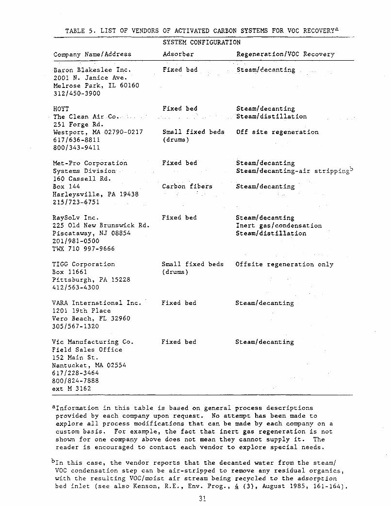
TABLE 5 . LIST OF VENDORS OF ACTIVATED CARBON SYSTEMS FOR VOC RECOVERYa SYSTEM CONFIGURATION
Company Name/Address Adsorb e r RegenerationlVOC Recovery
Baron Blakeslee Inc. 2001 N. Janice Ave. Melrose Park, IL 60160 3121450-3900
HOYT The Clean Air Co. 251 Forge Rd. Westport, MA 02790-0217 617 /636-8811 800 /343-9411
Met-Pro Corporation Systems Division 160 Cassell Rd. Box 144 Harleysville, PA 19438 215/723-675 1
RaySoLv Inc. 225 Old New Brunswick Rd. Piscataway, NJ 08854 201/981-0500 TWX 710 997-9666
TIGG Corporation Box 11661 Pittsburgh, PA 15228 412/563-4300
VARA International Inc. 1201 19th Place Vero Beach, FL 32960 305 /567-1320
Vic Manufacturing Co. Field Sales Office 152 Main St. Nantucket, MA 02554 6171228-3464 800 /824-7888 ext M 3162
Fixed bad
Fixed bed
Small fixed beds (drums )
Fixed bed
Carbon fibers
Fixed bed
Small fixed beds (drums )
Fixed bed
Fixed bed
Steamidecanting
Steam/decanting Steamldistillation
Off site regeneration
Steamldecanting Steam/decanting-air strippingb
Steamldecanting
Steamldecanting Inert gaslcondensation Steamldistillation
Offsite regeneration only
Steamldecanting
Steam/decanting
aInformation in this table is based on general process descriptions provided by each company upon request. explore all process modifications that can be made by each company on a custom basis. For example, the fact that inert gas regeneration is not shown for one company above does not mean they cannot supply it. The reader is encouraged to contact each vendor to explore special needs.
No attempt has been made to
this case, the vendor reports that the decanted water from the steam/ VOC condensation step can be air-stripped to remove any residual organics, with the resulting VOCImoist air stream being recycled to the adsorption bed inlet (see also Kenson, R.E., Env. Prog., 4 ( 3 ) , August 1985 , 1 6 1 - 1 6 4 ) .
31

4.3 Condensation
Condensation systems include both the condenser itself and often a
refrigeration system. Vendors listed below are able to supply both.
Alloy Fab, Inc. 200 Ryan St. P.O. Box 898 S. Plainfield, NJ 07080 201-753-9393
Croll-Reynolds Co., Inc. 751 Central Ave. P.O. Box 668 Westfield, NJ 07901 201-232-4200
Edwards Engineering 101 Alexander Ave. Pompton Plains, NJ 07444 201-835-2800
Pfaudler Co. 1000 West Ave. Box 1600 Roch?-ster, NY 14692 716-235-1000
32


5.0 EXAMPLE CASES
5.1 Adsorption
The purpose of t h i s s e c t i o n i s to provide t h e reader w i th an example of
t h e a p p l i c a t i o n of t h e design and t e c h n i c a l d i scuss ion of Sec t ion 2.1 t o a
s p e c i f i c case of VOC recovery by a c t i v a t e d carbon adsorpt ion. The r eade r
should a l s o r e f e r t o App i x A. This appe x con ta ins examples of some
vendor-supplied work s h e e t s which they ask t h e buyer t o complete i n o r d e r
t o conduct a prel iminary eva lua t ion of t h e buyer 's needs, u s u a l l y a t no
c o s t . Vendors w i l l normally supply prel iminary quotes and s p e c i f i c a t i o n s
based on t h i s information.
For any VOC recovery need, t h e buyer must know or o b t a i n c e r t a i n
information about t h e VOC-containing gas stream and t h e s i t e .
information has been summarized from t h e work s h e e t s of Appendix A and
s p e c i f i c va lues have been s e l e c t e d f o r t h e example exercise h e r e i n (see
Table 6 ) .
This
From t h i s information t h e buyer can make t h e following judgments and
c a l c u l a t i o n s about t h e VOC recovery system under cons ide ra t ion :
Gas Condir:.Qning--From t h e d i scuss ion i n Sec t ion 2.1, t h e gas-stream .
temperature, r e l a t i v e humidity, and t h e presence of d u s t i n d i c a t e t h e need
f o r gas condi t ioning upstream of t h e carbon beds.
m u s t accomplish p a r t i c u l a t e removal ( v i a a f i l t e r ) and coo l ing /
dehumidif icat ion t o approximately 80 t o lOO'F and <SOX RH ( v i a a
condenser /heat exchanger).
This gas cond i t ion ing
Sorbent Bed--The lower explosive l i m i t (LEL) for t o luene i n a i r is
12,000 ppm,2 thus t h e r e i s no need f o r d i l u t i o n of t h e gas stream f o r
s a f e t y reasons because up t o 25 t o 50% LEL can be t o l e r a t e d with some
s p e c i a l c o n t r o l s . The approximate so rben t bed s i z e can be c a l c u l a t e d from
t h e gene ra l gu ide l ines of Sec t ion 2.1 of 100 f t l m i n s u p e r f i c i a l v e l o c i t y
and t h e throughput of 20,000 f t 3 (STP)/min a t , s ay , 90'F:
Carbon bed c ross - s e c t i o n a l a r e a = r m 2 - 1 (460 + 90°R/492'R)
1 100 f t / m i n J
= 224 f t 2 .
33

TABLE 6. INFORMATION THE BUYER MUST SUPPLY
m
Flow rate of VOC-containing 20,000 ft3 ( ~ ~ ~ ) / m i n gas stream
VOC content of the gas stream 1,200 ppmtoluene in air
Gas-stream temperature 110.F
Impurities in the gas dust (trace amount)
stream
Relative humidity of the gas 75% stream
Value of recovered solvent $8.86/lb
Available utilities Steam 15 psig Electricity Sufficient (some vendors ask for
Cooling water Sufficient (some vendors ask for specific volts, amps)
specific supply temperature, pressure, and even water hardness)
Any space limitations None Operating schedule 8,000 hr/yr
34

From an isotherm of to luene adsorp t ion one a c t i v a t e d ~ a r b o n , ~ a t 70'F
and 1,200 ppm i n t h e VOC-containing gas , t h e " s a t u r a t i o n c a p a c i t y , " o r
adsorp t ion of to luene i s 30% ( i . e . , 1 l b of t h i s p a r t i c u l a r . I .
carbon w i l l adsorb 0.3 l b of to luene a t 70'F a t equi lbr ium).
a r b i t r a r y conserva t ive va lue f o r t h e "working capac i ty" of 25% of t h e
s a t u r a t i o n capac i ty f o r a t y p i c a l l -h r on- l ine ~ y c l e , ~ , ~ t h e working
capac i ty is:
Using an
Working capac i ty = (0 .25)(0.3 l b t o l u e n e l l b carbon)
= 0.075 l b t o l u e n e l l b carbon.
For s i n g l e VOCs o t h e r than to luene , t h e s a t u r a t i o n capac i ty a t i n l e t
temperatures of 70 t o 90'F, <50% RH, and 300 t o 5,000 ppm VOC w i l l vary
between roughly 20 and 40 wt percent ( i .e. , 1 l b carbon w i l l adsorb between
0.2 and 0.4 lb VOC & & b r i m a t these cond i t ions ) . Thus, us ing 25%
of t h i s s a t u r a t i o n capac i ty a s t h e working capac i ty , a r u l e of thumb
working capac i ty ( i n t h e absence of any o t h e r information) would be 5 t o 10
w t percent . B e cautioned t h a t it w i l l always be b e t t e r t o have
experimental d a t a f o r t h e VOC of i n t e r e s t , however.
The mass f low r a t e of to luene is:
Mass f low rate = rX00 x 1QZ l b - d e to luene i r 92 1 b 1 of t o luene 1 lb-mole gas J Llb-mole toluene]
369 l b to luene lh r - - Thus, t h e a c t u a l carbon requirement f o r a l - h r cyc le t i m e w i l l be:
Actual carbon - requirement 1 h r J l 1 1 0.075 l b toluene]
1369 l b tolueng1 1 1 hr1 r l b carbon 1 -
= 4,920 lb carbon.
Knowing t h a t t h e bulk dens i ty of mst granular a c t i v a t e d carbon is
about 30 l b l f t , 3 and t h a t t h e bed s u r f a c e area is 224 f t 2 , t hen t h e bed
depth i s c a l c u l a t e d t o be
35

Bed depth - - r-ncarbonl L-l-.-l t 30 l b / f t 3 J 1224 f t 2 J
= 0.73 f t . This bed depth is t o o shal low t o adsorb any b u t t h e smallest l e v e l s of
VOCs (such sha l low beds are, however, recommended f o r VOC concen t r a t ions i n
t h e range of 10 t o 100 ppm3). To o b t a i n a more appropr i a t e bed depth of a t
least 18 inches3, and p re fe rab ly 2 t o 3 f e e t , it w i l l be necessary i n t h i s
example t o inc rease t h e amount of carbon on - l ine from 4,920 l b
f t bed depth) t o :
(u s ing a 2-
Carbon needed - - ( 2 f t ) (24 f t 2 ) r30 ~b 1 on- l ine a t any t ft31 one t i m e
= 13,440 l b carbon.
This would probably be done with a th ree -vesse l system, wi th each
v e s s e l con ta in ing 6,720 l b carbon and wi th two vessels on - l ine a t any one
time. Such an arrangement would reduce t h e t o t a l amount of carbon needed
from a t o t a l of 26,880 l b carbon f o r a two-bed system (two 13,440-1b beds)
t o a t o t a l of 20,160 l b carbon ( t h r e e 6,720-1b beds) .
The steam usage, from Sec t ion 2.1 and based on a l - h r cyc le , w i l l be
approximately:
Steam usage = r-i r-i 1 l b carbon J L h r J
= 202 J.k steam h r .
The blower horsepower w i l l be:
Blower hp - - 1 (22400 f t3 /min )
134 hp. - -
VOC Reco very--Because steam is u s e d as t h e r egene ra t ing gas , t h e VOC
recovery s e c t i o n w i l l c o n s i s t of a condenser and a decan te r .
The condenser water needs w i l l be ( f o r a l -h r c y c l e ) :
36

Condenser water = r 1 (202 l b steam) f low 1100 l b s t e a d
- - 24 gal /min
One p o i n t of cau t ion is t h a t f o r t h i s p a r t i c u l a r case, t h e aqueous
s o l u b i l i t y of t h e VOC i n water is neg l ig ib l e . Thus the VOC can be
recovered d i r e c t l y and re-used o r s o l d and the decanted w a t e r is probably
s u i t a b l e f o r b o i l e r o r condenser feed. This may not be t r u e i n some
a p p l i c a t i o n s and t h e buyer should be c a r e f u l t h a t t h e recovered VOC is not
unduly contaminated wi th water , nor t h e w a t e r with VOC.
such cross-contaminat ion, even a t f a i r l y small l e v e l s , can d r a s t i c a l l y
a f f e c t t h e economics of VOC recovery.
The presence of
Economics--Based on t h e rough guidance of Sec t ion 3.1, t h e c a p i t a l c o s t
of t h e e n t i r e system is about
C a p i t a l c o s t = F S ~ O 1 (22,400 f t3 /min) lf t3lminJ
$44 5,000. - -
Carbon c o s t ( u u d e d . i n t h e above c a p i t a l c o s t ) w i l l be ( a t $ 4 / l b ) :
Carbon c o s t = ($4/1b)(20,160 l b carbon)
$80 , 6 4 0 . - -
A 5 t o 10-year t y p i c a l carbon l i f e implies a 10 t o 20%/year carbon
replacement c o s t , o r $8,100 t o $16,20O/yr.
Annual e l e c t r i c a l c o s t s a t $O.O6/kWh and 4 kW/1,000 f t3 /min and 8,000
h r / y r ope ra t ion w i l l be:
Annual e l e c t r i c i t y = r8000 hrl rs0.06 1 r 4 kw 1(22,400 f t3/mir . ) c o s t 1 yrJ 1 kWh J 11000 ft3/minJ
- - $43,000.
Annual steam c o s t ( a t $l/lOOO l b ) w i l l be:
Steam c o s t s = r202 1 ~ 1 r8000 h r l r SI 1 I hrJ 1 y r J 11000 1bJ
37

Annual condenser water c o s t ( a t $0.15/1000 g a l ) w i l l be:
Annual condenser = 124 sal1 f6-1 F snnn_hrl f $u 1 water c o s t 1 min J 1 h r J 1 y r J 11000 galJ
= $1,700.
There w i l l be a c r e d i t f o r t h e recovered VOC as w e l l . Assuming 95%
o v e r a l l e f f i c i e n c y and a va lue of $8.861100 I b f o r t o luene ,6 t h i s annual
c r e d i t w i l l be :
VOC recovery = fS8.86 1 f0.951 f369 b o 0 0 h r l c r e d i t 1100 1bJ 1 J L h r J 1 y r J
= $248,500.
I n summary f o r t h i s case, t h e c o s t s w i l l be roughly:
C a p i t a l c o s t $448,000 Annual ope ra t ing c o s t
Carbon replacement 8,100 - 16,200 E l e c t r i c i t y 43,000 Steam I , 600 Condenser w a t e r 1,700
Annual ope ra t ing c r e d i t $248,500.
To t h e annual ope ra t ing c o s t s must be added d i r e c t and i n d i r e c t l a b o r
and r e l a t e d i n d i r e c t annual expenses ( t a x e s , insurance, e t c . ) . The c a p i t a l
c o s t must be amortized and a f i n a l c o s t (or c r e d i t ) i n $ /y r determined.
This e x e r c i s e i s s p e c i f i c t o each small i n d u s t r i a l u s e r and is not completed
he re in .
f o r such an eva lua t ion .
However, t h e above should provide t h e use r w i th a s t a r t i n g po in t
5.2 Absorption
Although VOC recovery by abso rp t ion is not widely p r a c t i c e d , some
examples of i t s use are similar t o VOC recovery. One such example is t h e
recovery of aromatics from coke-oven gas us ing a heavy hydrocarbon absorbent
known as wash oil. S t r i p p i n g i s done by s t e a m . This o p e r a t i o n da res back
t o t h e 1880s i n t h e United S t a t e s and was used t o recover t h e r e l a t i v e l y
va luab le benzene, t o luene and xylene from t h e c o a l coking processes a s i n
s t e e l p l a n t s .
38

The example below i s summarized from S i l v e r and Hopton12 and a
d i scuss ion of t h e i r work by Kohl and Reisenfeld.5 Unfortunately, t h e
absorber and s t r i p p i n g column are not designed f o r coupled opera t ion .
However, t h i s example provides some idea of t h e major des ign and ope ra t ion
parameters of one well-proven VOC absorp t ion process .
I n l e t gas
VOC concent ra t ion Flow ra te Veloc i ty Temperature
11,000 ppm 418,000 f t 3 / h r 192 f t / m i n 73*F
Column
Diameter 9 f t Packing Wooden boards Surface area of packing O i l f low r a t e 83 gal lmin Removal e f f i c i e n c y 98.6X Operating p res su re 1 a t m G/L
110,000 f t 2
521 f t 3 g a s / f t 3 wash o i l - Column diameter 38 inches Wash o i l f low rate
Packing 1.4-inch r ings Wash o i l temperature 253.F Operating pressure 1 p s i g Steam f low r a t e 13.2 f t l m i n
14 gal lmin 1.8 g a l / m i n / f t 2
Other example cases are given i n T r e ~ b a l . ~ Costs can be es t imated from
a simple procedure given by Vatavuk and Neveril16, which involves t h e
c a l c u l a t i o n of t h e he ight and number of t r a n s f e r u n i t s us ing the VOC-
absorbent equi l ibr ium p r o p e r t i e s , gas and l i q u i d mass f low rates, and
phys ica l p r o p e r t i e s of t h e packing and column. From t h e des ign
c a l c u l a t i o n s , c o s t s a r e es t imated based on column s i z e , packing c o s t s , and
support equipment c o s t s . I n genera l , absorp t ion systems are more l abor and
c a p i t a l i n t e n s i v e than o the r VOC recovery techniques, a l though absorp t ion
system c o s t s can be competi t ive i n c e r t a i n app l i ca t ions .
39

5.3 Condensation
The following axample is taken from Purcell and Shareef (p. 4.7-lf.)
and demonstrates the condensation of a VOC from a stream typical of one to
which this technique can be applied--relatively low flow rate and high VOC
concentration. 2
For this case, we assume the following:
Inlet gas flow rate Inlet gas temperature 90'F voc styrene VOC concentration 13,000 ppm Moisture content negligible" Condenser operating pressure 1 atm
2000 ft3 (STP)/min
Removal efficiency required 90%
If the dew point of the inlet gas were close to the dew point of the VOC, then a desiccant might be necessary upstream of the condenser (see Section 2.3).
*
The key variable above is the required removal efficiency. To achieve
90% removal (i.e., an outlet concentration of 1,300 ppm), the temperature
of the gas stream must be reduced at least below that at which the
equilibrium vapor pressure of styrene in air at 1 atm is (1,300 x (760
mm Hg), or 1.0 mm Hg. This temperature is 2O'F for styrene. (In general,
knowledge of the equilibrium vapor pressure-temperature behavior for the
VOC(s) of interest is required.)
Because a coolant temperature of at most 2O'F is needed, refrigerated coolant fluid i s used. This is usually a "brine" solution, which can be
simply water with an appropriate antifreeze added (CaC12 is selected for
tbe example case2).
The condenser heat load is calculated by a straightforward heat balance
on the inlet and exit gas.
Condenser heat = 241,000 Btu/hr. load
The condenser surface area is given by the basic design equation of
Section 2.3 ( Q = U A AT). Assuming a countercurrent shell and tube
40

design, dT is the log mean temperature of the coolant and gas of the inlet minus the same difference at the outlet. This is somewhat arbitrary, but
often an "approach" temperature of 15 to 25*F is specified, meaning that the outlet gas temperature is specified to be 15 to 25*F higher than the
coolant temperature at the condenser outlet.
specifying that the coolant temperature rise be limited to 25'F (this may
be limited by the refrigeration equipment), and further assuming the inlet
coolant temperature to be 5*F, the log mean temperature difference, AT is
Using an approach of 15*F and
AT = (go* - 30 *F) (30 * - 5*F) In [ (90* - 30*F) /(ZOO - 5*F) J
= 32*F.
Calculation of U, the overall heat transfer coefficient, can be an
extremely time-consuming process, but is nevertheless necessary.
ely, some short-cut methods can result in considerable error, and
the reader is urged to go through the procedure of Kern13 or others to
obtain a reasonable value.
ft2 - *F as ""conservatively assumed" and cite Ludwiglf as a reference. Using this value, the heat exchanger area is:
Purcell and Shareef2 use a value of 20 Btu/hr-
A = Q I U A T
= (241,000 Btu/hr) (20 Btu/hr-ft2-*F) ( 3Z0F)
= 377 ft2.
The coolant flow rate, after calculating a coolant heat capacity of
0.65 Btu/lb-*F and recalling the specified temperature rise of 5'F tp 3Q0F,
is :
Coolant flow rate = fU.000 Btul r Ib-OF 1 f 1 1 1 hr 110.65 BtuJ LO'F - 5'FJ
= 14,800 lblhr.
The amount of styrene recovered at 90% efficiency will be:
41

A”-it of =
r ecove r ed
(0.90) mi,x!-&f+3(STPLi Fa-mole pas 1 TX.000 x 1Q-6 lb-mole s t y r enel styrene 1 min J 159 ft3 (STP)J 1 lb-mole gas J
rl“ I r u i llb-mole styreneJ 1 hr J
- - 407 lb styrenelhr.
The purchased equipment cost of a carbon steel shell and tube condenser
can be found to be about:
Purchase cost = $8,000. of condenser
To this must be added direct cost and indirect installation costs,
which are roughly 1202 of the condenser,16 to obtain the total capital cost
of the condenser of about $17,600. From Peters and Timmerhaus (p. 881),
the purchased equipment cost of the refrigeration unit is about $80,000. Assuming the same installation costs of 120%, the refrigeration unit capital cost will be $176,000, or 10 times that of the heat exchanger.
Operating costs include electricity for refrigeration unit and cooling
water pumps.
hr/yr operation and $O.O6/kWh (using a value of 1.5 kW per ton of refrigeration,2 with a 1 ton refrigeration equal to 12,000 Btulhr) to be:
Electricity for refrigeration can be estimated assuming 8,000
Electrical costs = fSO.061 fSann_hrl f241.00Q BrJal 1 kWh J 1 yr J L hr J
- f hr-ton 1 r1.5 kW1 112,000 BtuJ 1 ton J
-
= $14,50O/yr.
This may be a significant cost, and points out the economic reasons for
judicious use of condensation as a VOC recovery technique. The reader
should also refer to Chandrasekhar and Poulin ( p.126) where a similar
conclusion is implied.
42

6.0 REFERENCES
1.
2.
3.
4.
5.
6.
7.
8.
9.
10 *
11.
12.
13.
14.
15.
16.
17.
Kennedy, P.E., and J.C. McGill, "Adsorption Systems for Air Pollution Control in the Refining and Petrochemical Industries," Spring National AICE Meeting, Houston, TX, March 27-31, 1983.
Purcell, R.Y., and G.S. Shareef, "Evaluation of Control Technologies for Hazardous Air Pollutants," EPA-600/7-86-009a,b, February 1986.
Vic Mfg. Co., "Carbon Adsorption/Emission Control," (no date) Minneapolis, MN 55413.
Kohl, A.L., and F.C. Riesenfeld, Gas Purification, 4th ed., Gulf Publishing, Houston, 1985.
Kovach, J.L., in Handbook of Separation Techniques for Chemical Engineers, P.A. Schweitzer ed., McGraw Hill, 1979.
Peters, M.S., and K.D. Timmerhaus, Plant Design and Economics for Chemical Engineers, 3rd ed., McGraw Hill, 1980.
Buonicore, A.J., and L. Theodore, Industrial Control Equipment for Gaseous Pollutants, vol. I, CRC Press, 1975.
Chandresekhar, R., and E. Poulin, Control of Hydrocarbon Emissions from Cotton and Synthetic Textile Finishing Plants, report preparo,d for EPA by Foster-Miller, Inc., Waltham, MA, under contract 68-02-3134, May 1983.
Treybal, R.E., Mass Transfer Operations, 2nd ed., McGraw Hill, 1968.
Crawford, M., Air Pollution Control Theory, McGraw Hill, 1976.
Marchello, J.M., Control of Air Pollution Sources, Marcel Dekker, 1976.
Silver, L., and G.U. Hopton, J. SOC. Chem. Ind. (London), 61, March 1942, p. 37.
Kern, D . Q . , Process Heat Transfer, McGraw Hill, 1950.
Perry J.H., ed., Chemical Engineer's Handbook, 5th ed., McGraw Hill, 1973.
Ludwig, E.E., Applied Process Design for Chemical and Petrochenical Plants, vol. 111, Gulf Publishing, Houston, 1965.
Vatavuk, W.M., and R.B. Neveril, Capital and Operating Cost of Selected Air Pollution Control Systems, EPA-450/5-80-002, 1980. This report was also published in parts in Chemical Engineering, beginning in the October 6, 1980 issue.
Zenz, F.A., in Handbook of Separation Techniques for Chemical Engineers, P.A. Schweitzer, ed., McGraw Hill, 1979.
43


Appendix A
VENDOR WORKSHEETS FOR CARBON ADSORPTION SYSTEMS
44


DATE,
SOLVENT RECOVERY DATA SHEET
COMPANY
ADDRESS
,
NAME PHONE
PROCESS I N WHICH SOLVENT IS VAPORIZED
NORMAL OPERATION: HOURS PER D A Y DAYS PER WEEK
SOLVENT COMPOSITION (Give % of Components if mixture, and specify by weight or volume)
BOILING TEMPERATURE OF
MAXIMUM LOSS (Ibs./hr.)
HOW MUCH VARIATION OCCURS
MINIMUM LOSS (IbsJhr.)
VOLUME OF EXHAUST AIR: CFM TEMP. O F HUMIDITY
F A N STATIC PRESSURE REQUIRED -EXTERNALLY
CONTAMINANTS IN SOLVENT LADEN AIR: DUST
TAR/OILS ACID RESIN OTHER
UTILITIES AVAILABLE: STEAM (PSIG & BHP) COMPRESSED AIR (PSIG & SCFM)
ELECTRIC: (Vo l tage , Cycle, Phase)
COOLING WATER AVAILABLE: TEMP O F GPM PS I
DEGREE OF SEPARATION REQUIRED O F RECOVERED SOLVEVT MIXTURE
APPROXIMATE VALUE OF SOLVENT (Per Ib. or Gal.)
TYPE O F QUOTATION REQUIRED: BUDGET FINAL
PROJECT STATUS: IMMEDIATE 6-12 MONTHS OTHER
P lease Return to: HOYT CORP. Forge Road Westport, Massachusetts 02790
Toll Free 1-800-343-941 1 IN MASSACHUSETTS (617) 636-881 1 ATTENTION: Industrial Environmental Division SR 7 ?

160 CASSELL ROAD BOX 144 HARLEYSVILLE, PA 19438-9990 (215) 723-6751 TELEX 846-424
PROPOSAL REQUEST-PROJECT DATA SHEET
I. General:
A. Company
Address
Telephone ( 1 Ext . Date
Contact/ T i t l e
Location f o r Proposed Equipment '
B. P re fe r r ed Treatment: Best Choice O r
Concentration Followed By Adsorption O r I n c i n e r a t i o n
Adsorption w/ Steam
Thermal O r C a t a l y t i c I n c i n e r a t i o n With m e c u p e r a t i v e Heat Exchange
O r With 1b.j hr I Steam Generation a t PSIG
O r Vacuum Regeneration
Design Solvent Removal E f f i c i ency Desired
Performance Solvent Removal E f f i c i ency Desired %
%
C. Budget o r Firm Quotation Requested. Quotation Required By (da t e )
E s t i m a t e Date of Purchase Company RFQ No.
Estimated Date of Ins t a f l a t i on
11. Process:
A. Descr ipt ion
B. Volme of Exhaust: SCFM ( m X 1 (min)
Solvent Loading: lb./Hr. (-XI (min 1 Operating Pressure t o Proposed System: In . of water
Operacing Temperature t o Proposed System:
Re la t ive Humidity of P lan t Location % a t " F
--
O F
Operating A l t i tude i f above 2, 000 Ft . F t .
---- Duct S ize and Shape:
C . Operation : H r / Day Days/ Wk wks/ Yr
Continuous O r Batch
D . Contaminants : 1b.l fir. V O l . % ppm (Vol.) Mol. W t . B o i l P t . . 1.
2 .

D. Contaminants: l b . / h r . Vol. % ppm (Vol.) Mol. W t . B o i l P t .
4 .
5 .
-- E. P a r t i c u l a t e Present : Yes/No lb./ hr . % Combustible
._ Composition P a r t i c u l a t e Size D i s t r i b u t i o n
Phys ica l P r o p e r t i e s
F. Aerosol Present : Yes/No l b ./ h r . %Combustible
Composition
Phys ica l P r o p e r t i e s
G. U t i l i t i e s Avai lable:
E l e c t r i c vo It Cycle Phase
Compressed Air PSIG; Nitrogen PSIG
Cooling Water gpm P s i O F Allowable
Chi 1 led Water @m p s i OF Allowable
Steam lb/ h r p s i g O F
H. Insurance Coverage: FIA FM Other
I. I n s t a l l a t i o n P re fe r r ed :
Ground Indoor Outdoor Roof
J. Cont ro l Panel Location: On Unit O r Remote F t . From Unit
O r Both ; Indoors Out doors
K. Space Avai lab le f o r Equipment I n s t a l l a t i o n L W --- H
L. Should Equipment By-Pass be Provided
111. Carbon Adsorption:
A.
B. Intended use f o r recovered s o l v e n t :
C. P u r i t y r equ i r ed : Solvent Water
D. Value of recovered so lven t : $/Gal. E . Disposa l : Method
F. Disposal Cost: $/Gal.
Is recovered so lven t f o r r euse o r d i sposa l?
I V . Cat a l y t i c / Therma 1 Inc ine ra t i o n :
a t BTU/CF and A . Fuel Avai lab le : Type of Gas
p s i KO. o i l a t BTU/ Gal. and
p s i g : %su l fu r
B. Heat Recovery: YeslNo R e genera t ive A i r make-up
C . Steam Generat ion: YeslNo l b s . / h r PSIG

REQUEST FOR QUOTATION
1 Company Name Date
Address ci ty State Z i p
Person Supplying Information Phone
Furnish Quotation t o the Attent ion O f :
T i t l e Department
2 Purpose of System: A i r Po l lu t ion Control? (Requirement)
Reuse o f Solvent? Reuse o f A i r ? Other
Type o f operation i n which solvent was vaporized
Hours per s h i f t Sh i f ts d a i l y Days per week - Days per year
o . . . o . o ~ ~ o . . o o ~ . ~ o o o o ~ o ~ o o ~ o . . . ~ o . ~ . o o o o o ~ -
3 Vapor Compost t i o n X Vol. o r X W t .
a.
b.
C.
Maximum amount (lbs.) of solvent vaporized per hour
d. Is evaporation loss constant? I f not, explain haw much var ia t ion takes place
eels t h i s fnfonnation based on Usage o r stock analysfs
4 Cubic fee t per minute o f a i r handled Temperature o f a i r OF
I s t h i s an estimate or actual measurement
Maximum temperature of solvent laden a i r OF. Humidity
Impuri t ies present: Dust? Resins? O i l Vapor?
Paint? Acid Fumes? L i n t ? Other?
OVER

5 Cooling water temperature (max.) Water pressure P.S.I. Min,
Air pressure available P.S,I ,
Electrical power available V o l t s Cycles Phase,
Starter Full voltage Other
Avai lab4 7 i ty o f steam i s pounds/hour a t P.S. I.G.
6 Fieldman Recomnendations
Quotation Fonat: Budget Letter Long Form
FIELDMAN
V-APC 5187 12/82

Pollution Controls Division Vara International, Inc.
1201 19th Place, Vero Beach, FL. 32960 Telephone (305) 567-1520
Telex: 803460
ENGINEERING DATA SHEET SOLVENT RECOVERY SYSTEMS
NAME OF FIRM: DATE:
ADDRESS: TEL. NO. ( 1
ATTENTION:
ORIGIN OF THE SOLVENTS BRIEF DESCRIPTION OF PROCESS FROM WHICH SOLVENT IS EMITTED
I
IF MIXED SOLVENTS, WILL THE MIXTURE RECOVERED HAVE TO BE SEPARATED? El Yes [Ii No WHAT DEGREE O F SEPARATION IS NECESSARY?
COST OF SOLVENT(S)
WHATIS PERMISSIBLE WATER CONTENT
AIR OR GAS DATA DEGREE OF DUST
OR FLUFF OR VOLUME TEMPERATURE WATER PARTICULATES IS THERE ANMHING IN THE PROCESS LIABLE TO INTRODUCE
(cfm) ( O F ) CONTENT IN AIR STREAM A CORROSIVE GAS. ACID OR A COMPOUND?
I
PLANT OPERATIONS NORMAL HRS. DAY -- . - DAYS PER YEAR
UTlLITIES AVAILABLE STEAM PRESSURE SUPERHEAT
COOLING WATER TEMPERATURE HARDNESS
ELECTRICAL CHARACTERISTICS COMPRESSED AIR
DETAILS OF SPACE A V ~ L A B L E FOR RECOVERY PLANT INDOORS OR OUTDOORS? APPROX. HOW FAR IS PROPOSED SITEFROM PROCESS EMlSSlON OR S.L.A. SOURCE? -
ADD PAGES FOR ADDITIONAL INFORMATION OR REMARKS

C 0 ii;l P A N Y
&; O h 2 C .
a subsidiary of Purex Industries, Inc. R E P L Y T O
ZOO1 NORTH JANICE AVENUE MELROSE PARK ILLINOIS 601 60 AREA CODE 3 12-450 3900 CABLE PRX--BARB-MLPK TELEX 25-4701
C A R B O N A D S O R P T l O N D A T A S H E E T
D A T E
A D D R E S S
P R O C E S S F R O M VfHlCH S O L V E N T V A P O R IS E M I T T E D ,
H O U R S P E R D A Y D A Y S P E R WEEK D A Y S P E R Y E A R
P R E S E N T E X H A U S T : CFAl ; TEMP. O F ; HUliillDlTY %R H
S O L V E N T . (SI TO B E A D S O R B E D ( I F M O R E T H A N O N E G l V E P E R C E N T A G E O F EACH BY
\'!EIGHT OR V O L U M E - SPECIFY)
VOLUs*.lE I N A I R S T R E A i l l : PPtl : L B / t 1 R : O T t i E R .,
I : . lP[JRiTIES I N A I R STREA7.1 ( D U S T , O I L S , E T C . )

S T E A h l ( L B / H R , P S I G , B H P )
C O M P R E S S E D A I R ( P S I G , C U B I C F E E T h l l N U T E )
WATER ( T E M P E R A T U R E , G A L L O N S PER M I N U T E , PSIG)
IS Q U O T A T I O N R E Q U I R E D ? T Y P E : B U D G E T F O R M A L
P R O J E C T S T A G E : I h l M E D I A T E 3-6 M O N T H S 6-12 M O N T H S
C O M M E N T S :
PLEASE R E T U R N T O : B A R O N - B L A K E S L E E , -lNC. 3 4 M A N C H E S T E R D-RIVE W E S T F I E L D , N E W J E R S E Y 07030
A T T N : D I C K S E L Z N t C K .