
Recovery of Uranium from a Strong Sulfuric Acid … RECOVERY OF URANIUM FROM A STRONG SULFURIC ACID...
16
1 RECOVERY OF URANIUM FROM A STRONG SULFURIC ACID LOADED STRIP OR ELUATE By Grenvil Dunn and Yong Yong Teo Orway Mineral Consultants (WA) Pty Ltd, Perth, Australia Presenter and Corresponding Author Grenvil Dunn [email protected] ABSTRACT Solvent extraction (SX) and ion exchange (IX) have been the preferred processes for the recovery of uranium from acid leach solutions for several decades. When the sodium diuranate (SDU) refining route is selected then these SX and IX processes, when applied with strong acid strip or elution steps on their own, typically require the additional step of a partial neutralisation of the strong acid loaded strip or eluate solution using limestone, lime or other suitable alkali. The industry has often employed an acidic eluate from IX as the feed liquor to a tertiary amine SX circuit. The loading of uranium in this SX circuit is rarely greater than 10g/L and the SX circuit is prone to crud formation and organic degradation, resulting in the need for organic removal steps to reduce organic losses. This paper describes the recovery and upgrade of uranium from solvent extraction strong acid pregnant strip solution (PSS) employing an IX step to produce a high grade IX eluate suitable for converting to uranium oxide concentrate (UOC) employing the SDU refining route. The proposed process allows for a more efficient use of reagents required for the recovery of uranium. Testwork data from the ACAP Resources’ Letlhakane Uranium Project is provided to describe the development process.
Transcript of Recovery of Uranium from a Strong Sulfuric Acid … RECOVERY OF URANIUM FROM A STRONG SULFURIC ACID...

1
RECOVERY OF URANIUM FROM A STRONG SULFURIC ACID LOADED STRIP OR ELUATE
By
Grenvil Dunn and Yong Yong Teo
Orway Mineral Consultants (WA) Pty Ltd, Perth, Australia
Presenter and Corresponding Author
Grenvil Dunn
ABSTRACT
Solvent extraction (SX) and ion exchange (IX) have been the preferred processes for the recovery of uranium from acid leach solutions for several decades. When the sodium diuranate (SDU) refining route is selected then these SX and IX processes, when applied with strong acid strip or elution steps on their own, typically require the additional step of a partial neutralisation of the strong acid loaded strip or eluate solution using limestone, lime or other suitable alkali. The industry has often employed an acidic eluate from IX as the feed liquor to a tertiary amine SX circuit. The loading of uranium in this SX circuit is rarely greater than 10g/L and the SX circuit is prone to crud formation and organic degradation, resulting in the need for organic removal steps to reduce organic losses. This paper describes the recovery and upgrade of uranium from solvent extraction strong acid pregnant strip solution (PSS) employing an IX step to produce a high grade IX eluate suitable for converting to uranium oxide concentrate (UOC) employing the SDU refining route. The proposed process allows for a more efficient use of reagents required for the recovery of uranium. Testwork data from the ACAP Resources’ Letlhakane Uranium Project is provided to describe the development process.

2
INTRODUCTION
Solvent extraction (SX) and ion exchange (IX) have been the preferred processes for the recovery of uranium from acid leach solutions for several decades. Generally, either SX or IX could be applied to the recovery of uranium from acidic leach solution, with the selection depending on the specific flowsheet and costs. SX is generally selected based on costs when the uranium concentration in the acidic pregnant leach solution is high (>800-900 mg/L U). The loaded uranium in the SX process is often stripped with ammonia and ammonium sulfate (refer to Figure 1). However, the use of strong sulfuric acid may be preferred. This loaded strip solution needs to be partially neutralised with suitable alkali before a sodium diuranate (SDU) intermediate precipitation can take place. Cameco’s Rabbit Lake uranium operation in Canada (1,7) has utilised such a process. The partial neutralisation process produces gypsum that needs to be removed and disposed of, adding significantly to processing costs. This neutralisation process can be particularly costly if acid and alkali reagents are not readily available.
Figure 1 Uranium Recovery Employing SX with Strong Acid Strip
Similarly, for strong base anionic (SBA) IX processes (refer to Figure 2) a strong acid strip is often employed to elute uranium from the loaded resin. If a uranium SX process does not follow in the flow sequence after the IX, then a similar partial neutralisation step is required prior to the recovery of uranium oxide concentrate. Paladin Energy’s Kayelekera uranium operation in Malawi (2) has employed such a process.
Figure 2 Uranium Recovery employing IX with Strong Acid Strip
Industry often employs the acidic eluate from IX as the feed liquor to a tertiary amine SX circuit (refer to Figure 3). However, the loading of uranium in this SX circuit is rarely greater than 10g/L and the SX circuit is prone to crud formation and organic degradation, necessitating organic removal steps to reduce organic losses.

3
Figure 3 Uranium Recovery Employing IX followed by SX (Eluex Process) This paper describes the recovery and upgrade of uranium in a process employing IX from either SX strong acid pregnant strip solution (PSS) (refer to Figure 4) or IX strong acid loaded eluate solution (refer to Figure 5) to produce a high grade IX eluate suitable for converting to uranium oxide concentrate (UOC) employing sodium based reagents. This process allows for a more efficient utilisation of reagents required for the recovery of uranium and reduces processing costs.
Figure 4 Alternate Process for Uranium Recovery from a SX Strong Acid PSS Employing IX
Figure 5 Alternate Process for Uranium Recovery from an IX Strong Acid Loaded
Eluate Solution Employing IX
Extract Strip
Loaded Strip
SOLVENT EXTRACTION
URANIUM PREGNANT LEACH SOLUTION FROM
ACID LEACH
ION EXCHANGE
AMMONIUM DIURANATE PRECIPITATION
Sulfuric AcidBARREN LIQUOR RETURN TO LEACH
Ammonia / Ammonium Sulfate
AMMONIUM SULFATE BARREN LIQUOR
Conc Eluate

4
BACKGROUND ON A-CAP RESOURCES’ LETLHAKANE PROJECT
Mineralisation
The Letlhakane deposit consists of primary, oxide and secondary mineralisation (3). The primary mineralisation includes detrital heavy mineral accumulations containing orthobrannerite, uraninite, uraniferous zircon, monazite and uranium ionically bonded to long chain organic molecules in carbonaceous mudstone (humate ore). The oxide mineralisation includes coffinite and uranophane occurring as replacement of primary mineralogy. The oxide mineralisation also contains some hexavalent uranium minerals. The secondary mineralisation is generally hosted by calcrete, calcareous mudstones and fractured, non-calcarous oxidised mudstone. The uranium minerals are primarily hexavalent uranium minerals, such as carnotite, francvillite. Ore Composition The Letlhakane primary and oxide ore contains significant amount of organic carbon (3) (refer to Table 1).
Table 1 Letlhakane Ore Elemental Assay
Analysis Unit Serule West
Primary Kraken Primary
Gorgon Primary
Oxide
Al % 7.26 9.22 10.01 8.38
Fe % 0.89 0.68 1.15 2.72
Mg % 0.10 0.11 0.12 0.10
S % 0.33 0.13 0.68 0.2
Si % 25.4 25.8 23.3 -
U ppm 241 202 198 182
V ppm 228 329 522 234
Total C % 5.58 5.48 11.0 2.54
C Org % 4.34 4.34 9.59 2.43
CO3_C % 1.24 1.14 1.41 0.11
Leaching
Preg Robbing Acid and alkali leach regimes have been tested on the Letlhakane ores. It was found that the oxides and primary ores require strong acid leach conditions. Preliminary agitated leach testwork performed initially showed that the primary ore has a preg robbing tendency wherein leached uranium was reabsorbed from the pregnant liquor back into the solid as the leach progresses (refer to Figure 6).

5
Figure 6 Preliminary Preg Robbing Evaluation
Overcoming Preg Robbing Subsequent column leach testwork investigated the impact of varying lixiviant acid concentration and agglomeration acid addition. Higher acid concentration gives improved recovery (refer to Figure 7).
Figure 7 Impact of Leach Acid Concentration (3) The impact of solute concentration on column leaching was also investigated to determine the impact of leaching in mature leach liquor containing high solute concentrations. It was found that there was no difference in the uranium recovery between leaching in mature solution and in water. However, the acid consumption of the mature solution leach was significantly lower compared to that in water (refer to Figure 8).
-25.0
-20.0
-15.0
-10.0
-5.0
0.0
5.0
10.0
15.0
20.0
25.0
0 20 40 60 80 100
Ura
niu
m R
eco
ver
y (%
)
Leach Time (Hours)
U Ext (Calc from Liquor Assay) %
ConditionsTemperature : AmbientU Conc. in Initial Lixiviant : 269ppm USG : 19% SolidsEh : ~500mV (Ag/AgCl)Lixiviant Concentration : ~5g/L H2SO4
Acid Consumption : 13 -14 kg/tP80 : 75μm
0
10
20
30
40
50
60
70
80
90
100
0 10 20 30 40 50 60 70 80 90 100
Ura
niu
m E
xtr
ac
tio
n (
%)
Leach Time (Day)
Kraken Primary – 2m Column Leach Test
T1: 48 g/L H2SO4
T2: 99 g/L H2SO4
T3: 145g/L H2SO4
ConditionsAgglomeration Acid : 10kg/tP100 : 8mm

6
Figure 8 Impact of Solute Concentration (3) Two Stage Leach Extensive testing has identified that a two stage leach is optimal for the Letlhakane ores with the First Stage being a “cure” and the second stage a classical leach at 0.5 to 1 Molar sulfuric acid. Closed circuit sequential leaches were performed on the two primary and one mixed oxide ores and the PLS emanating from these were characterised and had a typical composition as shown in Table 2. The leach process selected was a two stage heap leach with strong acid (eg. 300g/L H2SO4) followed by weaker acid leach (60-100g/L) H2SO4. This two stage leach combination allows for aggressive leach in the initial period to maximise uranium extraction from the preg robbing ore.
Table 2 Letlhakane Column Leach PLS Composition
Species Concentration
(g/L)
U 0.3‐0.4
[H2SO4] ~ 60
S 70‐123
Al 9‐22
Ca 0.27‐0.55
Cu 0.1
Fe 18‐26
Mg 6
Mn 0.3
Mo 0.01
Zr 0.05
V 0.4
0
5
10
15
20
25
30
35
0 20 40 60 80 100
Aci
d C
on
sum
ptio
n (k
g/t)
Leach Time (Days)
Gorgon Primary Ore – 2m Column Leach
P24: Lixiviant makeup in water
P25: Lixiviant makeup in mature solution
ConditionsAgglomeration Acid :10kg/tLixiviant Concentration : 50g/L H2SO4
P100 : 19mm

7
Uranium Recovery
The high sulfur and iron concentrations in the PLS severely limited the selection of recovery options. Only SX could be employed for the recovery of uranium and this was only possible with low uranium loading (0.2-0.3 g/L/%) of the extractant. The high bisulfate loading also limited the strip liquor options. A 4M sulfuric acid strip liquor was identified as the only practical route available. Increasing the concentration of the uranium levels in the loaded strip was attempted by employing the loaded strip in an upgrade scrub, thereby improving the uranium loading on the solvent. This process route led to a very complex and costly SX circuit. Nano filtration, as a means of recycling the acid, was discounted due to the perceived high water requirements (in order to recover acid to the permeate) and concerns over membrane stability at the high acid concentration. The neutralisation of the loaded strip with an alkali such as limestone has been considered but discarded because of the following reasons:
Cost; The introduction of impurities such as manganese, which is pervasive in the inferior
limestone within southern Africa; Uranium mis-reporting to the precipitate; and Scale formation in process equipment, resulting in reduced plant availability
This left the project with a single alternate process to recover the uranium from the loaded strip - ion exchange - as detailed in this paper.
FLOWSHEET
The process flowsheet selected for Letlhakane is as shown in Figure 9.
Figure 9 Letlhakane Flow Sheet
Polymer
Loaded Strip
Solvent Extraction
SDU Precipitation
SDU Ressolution
Uranium Oxide Concentrate Precipitation
IX Barren
Sodium Carbonate
Sodium Bicarbonate
Uranium Ore Concentrate Product
Sodium Hydroxide
Hydrogen PeroxideSodium Hydroxide
Agglomeration & Heap Leach
Ion Exchange
Crushed Ore (F100 19mm)
Sulfuric Acid
Sulfuric Acid
Sulfuric Acid
PLS SX Raffinate
Conc. Eluate SDU Barren liquor

8
Despite the limited uranium recovery flowsheet options available to treat the leach PLS, the process proposed in this schematic has significant reagent utilisation efficiency (refer to Figure 10):
Sulfuric acid in SX raffinate recycled in full to the leach Sulfuric acid in IX barren near quantitatively recycled to the SX Strip as feed Sodium carbonate in the SDU Barren recycled quantitatively to the IX Strip feed
Figure 10 Uranium Recovery - Reagent Recycle
METALLURGY
Solvent Extraction
The extractant employed in the Letlhakane testwork was a mixture of 5 vol % Alamine 336 (tertiary amine extractant) and 2.5 vol % iso-decanol (phase modifier) in Shellsol 2046 diluent. Extraction The extraction reaction in SX can be described by Equation 1 H4UO2(SO4)3 (aq) + 4R3NH2SO4(o) → [R3NH]4UO2(SO4)3 (o) + 4H2SO4(aq) Equation 1 Strip A 4 molar sulfuric acid strip liquor was employed in the Letlhakane testwork. The strip reaction in SX can be described by Equation 2 [R3NH]4UO2(SO4)3 (o) + 4H2SO4(aq) → H4UO2(SO4)3 (aq) + 4(R3NH)HSO4(o) Equation 2 This PSS became the feed to the IX circuit. Ion Exchange The IX resin employed for the recovery of uranium from PSS was a chelating type resin Lanxess TP 260 resin with aminomethyl phosphonic functional group. Adsorption The uranium adsorption can be described by Equation 3 below.
H4UO2(SO4)3(aq) + ResPO3H2(r) → (ResPO3)UO2(r) + 3H2SO4(aq) Equation 3 Elution The adsorbed uranium was released in the elution stage by using a 2 molar sodium carbonate or a combination of 2 molar sodium carbonate and sodium bicarbonate solution. These reactions can be described by equations 4 to 6.
(ResPO3)2UO2(r) + 3Na2CO3(aq) → ResPO3Na2(r) + Na4UO2(CO3)3(aq) Equation 4
2ResPO3H(r) + 2Na2CO3(aq) → 2ResPO3.Na(r) + 2NaHCO3 Equation 5
ORE SOLVENT EXTRACTION
ION EXCHANGE
SODIUM DIURANATE
PRECIPITATION
PURE AND CONCENTRATED SDU PRECIPITATE
Sodium Carbonate And Sodium Bicarbonate Sodium Hydroxide
LEACH
Sulfuric AcidSulfuric Acid

9
Resin Protonation and Deprotonation The resin requires some of the functional groups to be deprotonated after the adsorption of uranium and this was done with a very weak caustic soda solution (~ 4g/L). Similarly, after the elution step, these same functional groups are reprotonated employing a bleed stream of barren solution.
Deprotonation : 2NaOH(aq) + ResPO3H2(r) → ResPO3Na2(r) + 2H2O (l) Equation 7 Protonation : H2SO4(aq) + ResPO3Na2(r) → ResPO3H2(r) + Na2SO4 (aq) Equation 8
Uranium Product Recovery The uranium recovery metallurgy from the IX eluate was that of a standard alkali leach and incorporated :
SDU precipitation, followed by SDU resolution, followed by UOC precipitation
The chemistry of these processes can be summarised as follows: Sodium Diuranate Precipitation (SDU) The SDU precipitation rejects molybdenum to the barren solution and collects the uranium as a diuranate.
2Na4UO2(CO3)3 (aq) + 6NaOH (aq) → Na2U2O7(s) + 6Na2CO3(aq) + 3H2O(l) Equation 9
SDU Resolution Sulfuric acid was employed to redissolve the uranium while rejecting hydrolysed zirconium basic sulfate and other similar impurities to the residue.
Na2U2O7 (s) + 7 H2SO4 (aq) → 2H4UO2(SO4)3 (aq) + Na2SO4(aq) + 3H2O(l) Equation 10
Uranium Oxide Concentrate Precipitation The uranyl sulfate was then hydrolysed under oxidative conditions.
H4UO2(SO4)3(aq) +H2O2(aq) + 6NaOH(aq) + (x-6)H2O(l)→UO4•xH2O(s) + 3Na2SO4(aq) Equation 11
TEST WORK
Ion Exchange
Batch sighter tests followed by locked cycle batch tests were conducted prior to the integration of the elution step into the recovery test program. Sighter Batch Testwork Batch loading and kinetic elution tests were completed as part of the sighter batch testwork. The elution regime for the TP260 was more complex than that required for most resins employed in the uranium service and considerable attention was paid to both the deprotonation and elution steps. The results provided in Table 3 were obtained from the sighter testwork.

10
Table 3 Elution Conditions and Results
Sighter Test 1 2 3 4
Resin Deprotonation 40g/L NaOH 10g/L NaOH 10g/L NaOH -
Deprotonation Retention Time (h)
1.4 1.5 1.8
Eluant 1 Liquor 250g/L Na2CO3 200g/L Na2CO3 100g/L Na2CO3 200g/L Na2CO3 / 50g/L NaHCO3
Elution 1 Retention Time (h)
1 1 1 1
Eluant 2 Liquor 250g/L Na2CO3 pH 11 Na2CO3 50g/L Na2CO3 -
Elution 2 Retention Time (h)
2.9 2.7 5.8 -
Uranium on Loaded Resin
(g U/L wsr) 139 162 135 126
Uranium Stripped (g U/L wsr)
97 149 126 124
% Uranium Eluted 70% 92% 93% 98%
This sighter testwork supported:
The use of a sodium carbonate and bicarbonate eluant; and Low sodium hydroxide concentration for deprotonation.
Integrated Batch Testwork The IX step was then incorporated into the flowsheet as part of integrated batch testwork. The flowsheet to this point had included the following steps:
Leach; SX; IX; and UOC Recovery.
The integrated batch testwork employed the three SX loaded strip liquors shown in Table 4 as feeds to IX adsorption. .
Table 4 Integrated Batch Testwork Assay of SX Loaded Strip
Species Test 1 mg/L
Test 2 mg/L
Test 3 mg/L
U 4165 3834 3797 Al 6.6 3.2 1.7 Fe 9.5 4.1 2.8 Ca 6.7 5.8 6.6 Na 14 13 14
H2SO4 370,000 363,000 332,000 The IX loading took place in a Lead-Lag 1 & 2 circuit (refer to Figure 11)

11
Figure 11 IX Loading Circuit Set up
The elution included the following steps:
Deprotonation; Wash; Sodium carbonate/bicarbonate elution; Wash; and Reprotonation.
The results for the three tests undertaken in the integrated batch elution testwork are provided in Table 5.
Table 5 Integrated Batch Testwork Elution Results
Test Test 1 Test 2 Test 3
Loaded Lead (g U/L wsr) 76.5 70.1 79.3
Loaded Lag 1 (g U/L wsr) 58.6 38.6 14.2
Loaded Lag II (max) (g U/L wsr) 0.05 0.05 0.05
Barren liquor (g U/L) <1 <1 <1
Eluant Flowrate (BV/h) Stage 1 = 0.5
Stage 2 = 0.5 0.5
Stage 1 = 1.5
Stage 2 = 0.5
Eluant (BV Na2CO3/ NaHCO3) Stage 1 = 3
Stage 2 = 2 5
Stage 1 = 1.5
Stage 2 = 5
% Uranium Eluted 99.9% 99.9% 99.9%
Conc. Eluate Concentration (U g/L) 27.8 43.4 69.5
In excess of 99.9% of the uranium was eluted employing a DNA determination on the ashed resin. The elution kinetics, however, were relatively slow, requiring 10h at 0.5BV/h. Uranium Product Recovery The combined uranium IX concentrated eluate composition is given in Table 6. The TP260 resin did not offer high selectivity for uranium over other cations. However, acceptable separations were achieved with the standard recovery flowsheet comprising of
SDU precipitation;

12
SDU resolution; UOC precipitation employing hydrogen peroxide and sodium hydroxide.
Table 6 Composition of Combined Eluate used in the Uranium Product Recovery
Testwork
Composition Units Test 1 Test 2 Test 3
U g/L 20 32 57
Na g/L 67 47 42
S g/L 1.5 1.0 0.15
CO3 (total) g/L 96 97 81
Ca mg/L 43 40 112
pH mg/L 9.5 9.8 8.6
Table 7 shows the uranium oxide product composition.
Table 7 Uranium Oxide Product Composition
Element Combined
Product (% of U)
ASTM UOC Specification (No Penalty)
(% of U)
Zr <0.004 0.01
Ag <0.001
Al <0.01
As <0.01 0.05
B <0.005 0.005
Ba <0.002
Cd <0.001
Cr <0.001
Fe <0.04 0.15
Hg <0.001
K <0.08 0.20
Mn <0.001
Mo <0.001 0.10
Na <0.05 0.50
P <0.02 0.10
Pb <0.001
S <0.17 1.00
Se <0.01
Si <0.02
Th <0.001 1.00
Ti <0.001 0.01
V <0.001 0.06
F <0.01 0.01
Cl <0.05 0.05
13
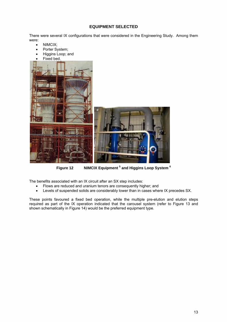
EQUIPMENT SELECTED
There were several IX configurations that were considered in the Engineering Study. Among them were:
NIMCIX; Porter System; Higgins Loop; and Fixed bed.
Figure 12 NIMCIX Equipment 5 and Higgins Loop System 6
The benefits associated with an IX circuit after an SX step includes: Flows are reduced and uranium tenors are consequently higher; and Levels of suspended solids are considerably lower than in cases where IX precedes SX.
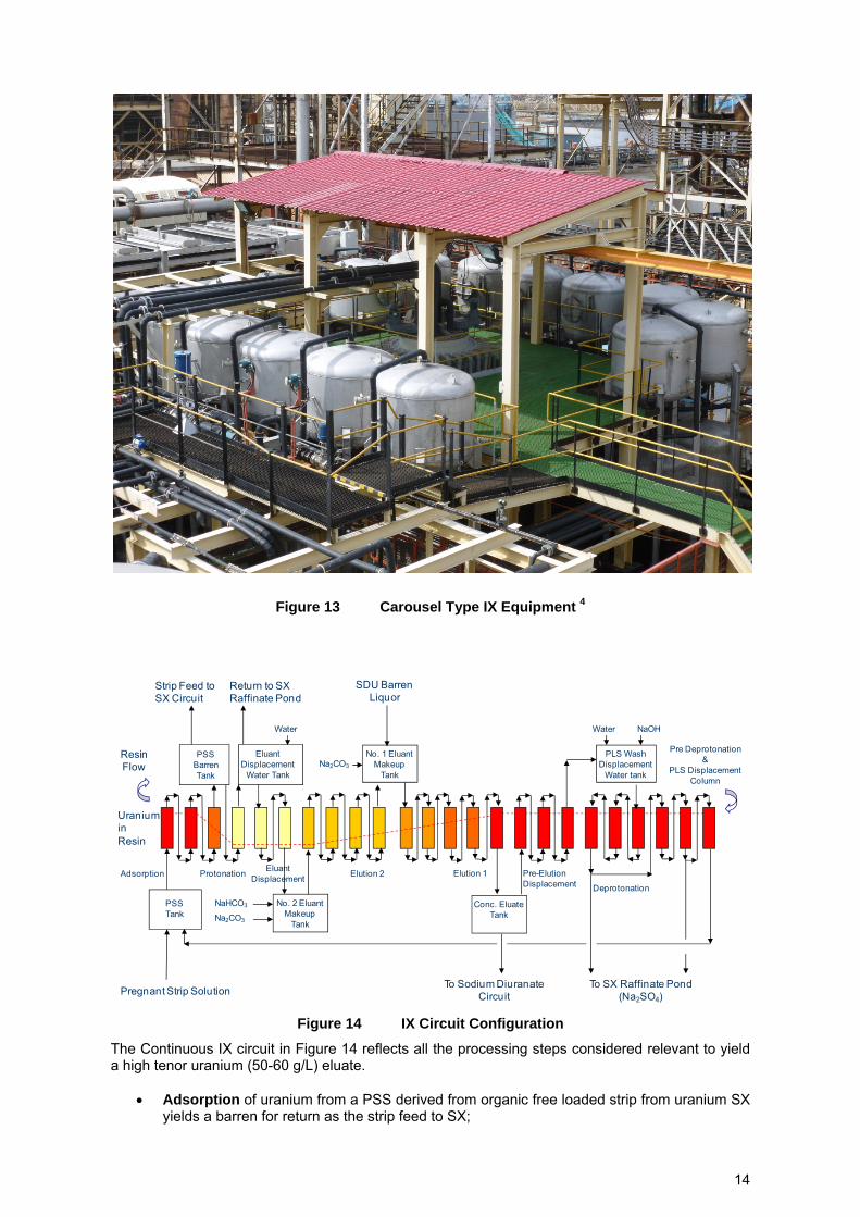
These points favoured a fixed bed operation, while the multiple pre-elution and elution steps required as part of the IX operation indicated that the carousel system (refer to Figure 13 and shown schematically in Figure 14) would be the preferred equipment type.
14
Figure 13 Carousel Type IX Equipment 4
Figure 14 IX Circuit Configuration
The Continuous IX circuit in Figure 14 reflects all the processing steps considered relevant to yield a high tenor uranium (50-60 g/L) eluate.
Adsorption of uranium from a PSS derived from organic free loaded strip from uranium SX yields a barren for return as the strip feed to SX;
Protonation
UraniuminResin
PSSBarrenTank
PSSTank
ResinFlow
Adsorption
Pregnant Strip Solution
Strip Feed to SX Circuit
Elution 1Elution 2 Pre-Elution Displacement
Return to SX Raffinate Pond
EluantDisplacement
Water Tank
Water
No. 2 EluantMakeup
Tank
EluantDisplacement
NaHCO3
Na2CO3
No. 1 EluantMakeup
TankNa2CO3
Conc. EluateTank
To Sodium DiuranateCircuit
PLS Wash Displacement
Water tank
Water NaOH
To SX Raffinate Pond (Na2SO4)
Deprotonation
Pre Deprotonation&
PLS Displacement Column
SDU Barren Liquor

15
PLS displacement wash where the leading column loaded to near maximum adsorption with uranium is then subjected to a PLS displacement employing water wash. This wash also serves to remove PLS prior to Deprotonation;
Deprotonation in which a weak sodium hydroxide liquor is fed co-current with the flow to remove residual acid (protons) in the resin;
Pre-Elution Wash, a step in which some concentrated eluate is employed to displace any barren deprotonation wash fluid;
Elution, which is undertaken in two stages. The first stage employing sodium carbonate/ SDU barren and the second employing a blend of sodium carbonate and bicarbonate. The SDU Barren contains some residual sodium hydroxide which is neutralised in the elution process;
Eluant Displacement Wash employing water; and Protonation – a step in which the resin is contacted with acid employing a strip liquor bleed
stream.
LAYOUT The columns are fixed in position and are serviced by multiport rotary valve. A typical layout for the CIX columns is shown in Figure 15.
Figure 15 Typical CIX Layout Columns Only
TYPICAL CIX CAPITAL COST
For a generic process treating approximately 3.5 M/lb U3O8 / year, the CIX rig capital costs is US$
Rotary valve and column installed cost 3,100,000
Ancillaries installed cost 4,700,000
Resin first fill 1,200,000
Civil, structural, electrical and instrumentation 7,000,000

16
TYPICAL CIX OPERATING COST
The reagents employed and consumed directly for a typical IX circuit are: kg/kgU
Sodium carbonate 0.5-0.6
Sodium bicarbonate 0.4-0.5
Sodium hydroxide 0.1
Sulfuric acid 1.5 The reagents operating costs for the CIX plant treating 3.5 M/lb U3O8 / year is expected to be US$0.27 /lb U3O8. The overall recovery circuit operating cost (C1) is expected to be approximately US$ 4.00 /lb U3O8 (SX + IX+ SDU + UOC precipitation). This compares with US$6-8 / lb U3O8 for the cost of recovering UOC in acid leach processes.
CONCLUSION
The branneritic and preg robbing nature of Letlhakane ore has predicated a high sulfate and sulfuric acid PLS for the treatment in the uranium recovery circuit. SX was the only recovery step that showed any merits and then not without having to use a strong acid strip to recover the uranium from the extractant. Continuous IX offered a low operating cost option for treating the uranium SX loaded strip. The IX circuit brings to the overall recovery (SX and IX) and refining (SDU and UOC) flowsheet a cost competitive operating cost structure which is significantly lower than most conventional acid leach circuits. The overall uranium recovery from the leach PLS to product was greater than 99%.
ACKNOWLEDGEMENT
The authors wish to thank the Board of ACAP Resources and particularly Dr Paul Woolrich for the support and permission to publish this paper.
REFERENCES
1. Uranium Extraction Technology, Technical Reports Series No. 359, International Atomic Energy Agency, Vienna, 1993, P305-313
2. Marsh, D. and Hladun, D., An Overview of the Kayelekera Uranium Mine in Malawi, Alta Conference, 2010
3. Cairns, D., et. al., Development of the Letlhakane Uranium Project, presented at Alta 2012 Conference by ACAP Resources, 2012
4. Puritech Website : http://puritech.be 5. Mining Magazine, June 1996 6. Severn Trent Services website : www.severntrentservices.com 7. Milde, W.W., Rabbit Lake Project – Milling and Metallurgy, Mineral Processing, Dec 1989
![Sulfuric Acid is[1]](https://static.fdocuments.net/doc/165x107/552847e14a7959c93d8b4684/sulfuric-acid-is1.jpg)


