Recovering Scenes by Polarization Analysis
7
Recovering Scenes by Polarization Analysis Yoav Y. Schechner and Nir Karpel Dept. of Electrical Engineering Technion - Israel Inst. Technology Haifa 32000, ISRAEL [email protected] , [email protected] Abstract— We devise a computer vision approach which removes degradation effects in optical underwater imaging. It exploits natural illumination. By analysis of the physical effects of visibility degradation, we associate natural backscat- ter with partial polarization of light. This is contrary to prior studies which have associated polarization with light emanating from the objects, rather than the backscatter. Our algorithm takes advantage of this aspect to invert the image formation process. In this paper we show that our method achieves a much better visibility recovery, compared to prior methods. This is demonstrated in underwater experimentation in the sea. In addition, the physics-based analysis of the polarization filtered images recovers a range-map of the scene. This allows 3D rendering of the scene from various viewpoints. I. UNDERWATER VISIBILITY PROBLEMS Underwater visibility is typically very poor [6][13][16][19][33][40]. For this reason, a lot of research effort is being invested in acoustic imaging, which can penetrate water more easily. However, acoustics sensors have their own shortcomings: they have a much lower spatial resolution than optical systems [3][4][25]; sound waves may undergo convoluted and distorted paths in the water due to refraction between layers of water [17]; reverberations create false detections [35], while scattering by tiny particles having acoustic contrast creates speckle noise [17][24]; sonar detection is prone to noise coming from electronic sources and suffers from directionality problems associated with sidelobes of the acoustic antenna [39]. Acoustic sensors trade spatial resolution for detection range, since acoustic radiation is attenuated quickly in water as the acoustic frequency increases [17]. Low frequencies require systems that are very large [12][34], in order to obtain any spatial resolution. In addition, active sonar is disadvantageous in stealth tasks [3]. Finally, the visual interpretation of acoustic images is difficult, since we as humans have not evolved to view fields of acoustic reflectances. To avoid these problems, there is need for underwater optical imaging systems. However, in addition to disrupting human interpretation of scenes, the poor underwater optical visibility hinders computer vision [10] tasks, e.g., those based on stereo triangulation or on structure from motion. It is important to alleviate these visibility problems, in order to enhance engineering applications [1][2][9][11] [19][23][32][33][40], as well as research in marine biol- ogy [8][15][37][40] archaeology [6] and mapping [41]. We have recently introduced a physics-based approach for recovery of visibility when imaging underwater scenes in natural illumination [28]. It explicitly relies on the image formation process, and thus accounts for the complex spa- tially varying degradation effects which exist in submerged scenes. The approach relies on raw images taken through different states of a polarizing filter. We have shown that due to the polarization of natural backscatter (veiling light), these raw images have slight photometric differences. Thus, these differences serve as initial cues for an algorithm that factors out the effects that degrade underwater scenes. In this paper we first give a brief overview of our method. Then, we concentrate on comparison of its results to ones obtained by prior methods. In particular, we show that the method is superior to other methods based on polarization, as well as to standard image processing tools. The reasons for this superiority is explained. II. I MAGE FORMATION MODEL A. The Signal As depicted in Fig. 1, under natural illumination we sense two sources. The first source is the scene object. The image of this source is degraded, as we detail below, and we term it as the signal. The second source is the ambient illumination. Part of the ambient light is scattered towards the camera by the particles in the water, and is termed veiling light or backscattered light [16][21]. The description of the latter component is given in Sec. II-B. In the literature, the signal is typically represented as a sum of two components, termed direct transmission and forward scattering [16][21]. The direct transmission is given by D(x, y)= L object (x, y)e −ηz , (1) where η is the attenuation coefficient, and z is the distance to the object. This distance depends on the pixel coordi- nates x and y. Here L object is the object radiance we would have sensed, had there been no scattering and absorption along the line of sight (LOS). The forward scattering component is similar to the direct transmission. However, it represents light scattered at small angles relative to the LOS, causing image blur. It has been expressed as F (x, y)= D(x, y) ∗ g z (x, y) , (2) where D is given by (1) and g z is a point spread function (PSF). The PSF [16][21] is parameterized by the distance z , since the farther the object, the wider the support of the blur kernel.
Transcript of Recovering Scenes by Polarization Analysis
Recovering Scenes by Polarization Analysis
Yoav Y. Schechner and Nir Karpel
Dept. of Electrical EngineeringTechnion - Israel Inst. Technology
Haifa 32000, [email protected] , [email protected]
Abstract— We devise a computer vision approach whichremoves degradation effects in optical underwater imaging.It exploits natural illumination. By analysis of the physicaleffects of visibility degradation, we associate natural backscat-ter with partial polarization of light. This is contrary toprior studies which have associated polarization with lightemanating from the objects, rather than the backscatter. Ouralgorithm takes advantage of this aspect to invert the imageformation process. In this paper we show that our methodachieves a much better visibility recovery, compared to priormethods. This is demonstrated in underwater experimentationin the sea. In addition, the physics-based analysis of thepolarization filtered images recovers a range-map of the scene.This allows 3D rendering of the scene from various viewpoints.
I. UNDERWATER VISIBILITY PROBLEMS
Underwater visibility is typically very poor[6][13][16][19][33][40]. For this reason, a lot of researcheffort is being invested in acoustic imaging, whichcan penetrate water more easily. However, acousticssensors have their own shortcomings: they have a muchlower spatial resolution than optical systems [3][4][25];sound waves may undergo convoluted and distortedpaths in the water due to refraction between layers ofwater [17]; reverberations create false detections [35],while scattering by tiny particles having acoustic contrastcreates speckle noise [17][24]; sonar detection is proneto noise coming from electronic sources and suffers fromdirectionality problems associated with sidelobes of theacoustic antenna [39]. Acoustic sensors trade spatialresolution for detection range, since acoustic radiationis attenuated quickly in water as the acoustic frequencyincreases [17]. Low frequencies require systems thatare very large [12][34], in order to obtain any spatialresolution. In addition, active sonar is disadvantageousin stealth tasks [3]. Finally, the visual interpretation ofacoustic images is difficult, since we as humans have notevolved to view fields of acoustic reflectances.
To avoid these problems, there is need for underwateroptical imaging systems. However, in addition to disruptinghuman interpretation of scenes, the poor underwater opticalvisibility hinders computer vision [10] tasks, e.g., thosebased on stereo triangulation or on structure from motion.It is important to alleviate these visibility problems, inorder to enhance engineering applications [1][2][9][11][19][23][32][33][40], as well as research in marine biol-ogy [8][15][37][40] archaeology [6] and mapping [41].
We have recently introduced a physics-based approachfor recovery of visibility when imaging underwater scenes
in natural illumination [28]. It explicitly relies on the imageformation process, and thus accounts for the complex spa-tially varying degradation effects which exist in submergedscenes. The approach relies on raw images taken throughdifferent states of a polarizing filter. We have shown thatdue to the polarization of natural backscatter (veiling light),these raw images have slight photometric differences. Thus,these differences serve as initial cues for an algorithm thatfactors out the effects that degrade underwater scenes.
In this paper we first give a brief overview of our method.Then, we concentrate on comparison of its results to onesobtained by prior methods. In particular, we show that themethod is superior to other methods based on polarization,as well as to standard image processing tools. The reasonsfor this superiority is explained.
II. IMAGE FORMATION MODEL
A. The Signal
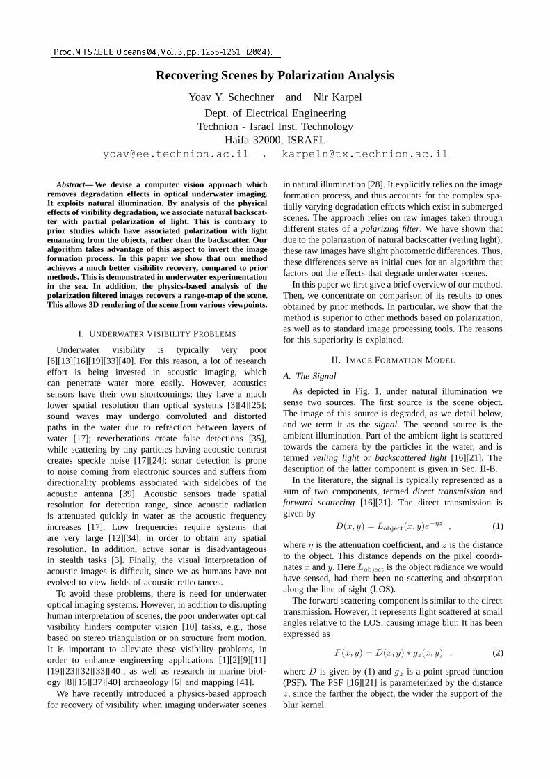
As depicted in Fig. 1, under natural illumination wesense two sources. The first source is the scene object.The image of this source is degraded, as we detail below,and we term it as the signal. The second source is theambient illumination. Part of the ambient light is scatteredtowards the camera by the particles in the water, and istermed veiling light or backscattered light [16][21]. Thedescription of the latter component is given in Sec. II-B.
In the literature, the signal is typically represented as asum of two components, termed direct transmission andforward scattering [16][21]. The direct transmission isgiven by
D(x, y) = Lobject(x, y)e−ηz , (1)
where η is the attenuation coefficient, and z is the distanceto the object. This distance depends on the pixel coordi-nates x and y. Here Lobject is the object radiance we wouldhave sensed, had there been no scattering and absorptionalong the line of sight (LOS).
The forward scattering component is similar to the directtransmission. However, it represents light scattered at smallangles relative to the LOS, causing image blur. It has beenexpressed as
F (x, y) = D(x, y) ∗ gz(x, y) , (2)
where D is given by (1) and gz is a point spread function(PSF). The PSF [16][21] is parameterized by the distancez, since the farther the object, the wider the support of theblur kernel.
yoav
Proc. MTS/IEEE Oceans'04, Vol. 3, pp. 1255-1261 (2004).
natural
illumination
us
y
aw e
x
cfrt ea
r
B
S
objectLsignal
camera
polarizingfilter
distance z
backscatteredlight
radiance
scattering
object
Fig. 1. [Dashed rays] Backscatter: Light coming from a source is scattered towards the camera by particles in the water. This componentincreases with the distance z to the object. [Solid ray] Signal: Light emanating from the object is attenuated and somewhat blurred asz increases. Without scattering and absorption along the line of sight (LOS), the object radiance would have been Lobject .
Accounting for both the direct transmission (1) and theforward scattering (2), we define the signal as
S = D + F . (3)
In addition, we define an effective object radiance Leffectiveobject
asLeffective
object = Lobject + Lobject ∗ gz . (4)
It is a somewhat blurred version of Lobject. From (1,2,3),the signal is
S = e−ηz Leffectiveobject . (5)
In [28] we demonstrated that blur due to forward scat-tering is generally not the dominating contributor to imagedegradation. Rather, image degradation occurs mainly dueto the veiling light, described in Sec. II-B. For this reason,our recovery approach, described in Sec. III, does not at-tempt to compensate for image blur, say by deconvolution.Hence, we do not seek, at this point, to recover Lobject, butmake do with the recovery of Leffective
object from the signal. Forthis reason, we prefer the signal representation of (5), ratherthan using the more familiar representation of (3).
B. Veiling Light
Veiling light is often referred to in the literature asbackscatter. We thus use these terms interchangeably. It iscaused by scattering the ambient illumination into the LOSand towards the camera by suspended particles (Fig. 1).Consider a single distant source that illuminates the LOSfrom direction �r = (θ, ϕ) relative to the LOS, with intensityIsource. Following [16][21], the contribution of this sourceto the backscatter is
B (�r) =∫ z
0
β (θ) Isource (�r) e−ηl
[1 − f
l + l0
]2
dl (6)
where f is the focal length of the camera and l0 is thedistance between the lens and the underwater housingwindow. Here β(θ) is the angular scattering coefficient.
In [28] we have shown that (6) can be greatly simplified.Integrating the illumination distribution caused by distantlight sources in all directions, the backscatter can beapproximated by
B = B∞(1 − e−ηz
), (7)
camera
camera
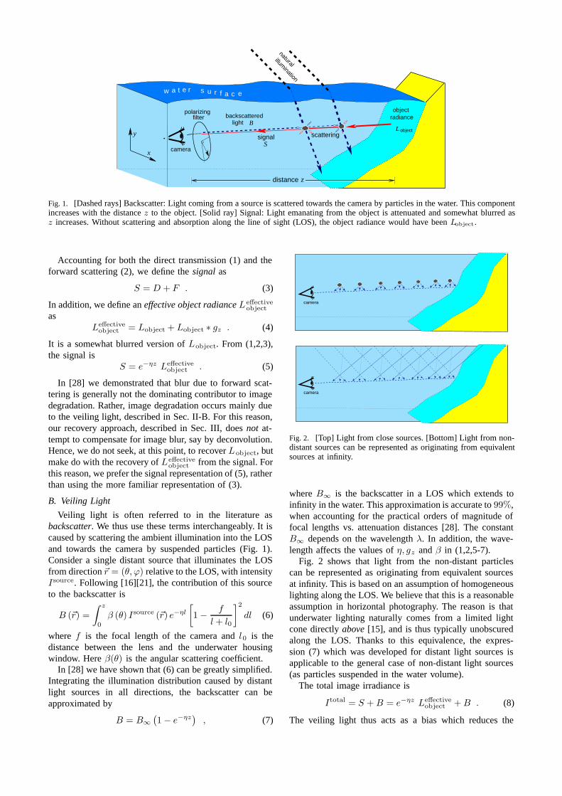
Fig. 2. [Top] Light from close sources. [Bottom] Light from non-distant sources can be represented as originating from equivalentsources at infinity.
where B∞ is the backscatter in a LOS which extends toinfinity in the water. This approximation is accurate to 99%,when accounting for the practical orders of magnitude offocal lengths vs. attenuation distances [28]. The constantB∞ depends on the wavelength λ. In addition, the wave-length affects the values of η, gz and β in (1,2,5-7).
Fig. 2 shows that light from the non-distant particlescan be represented as originating from equivalent sourcesat infinity. This is based on an assumption of homogeneouslighting along the LOS. We believe that this is a reasonableassumption in horizontal photography. The reason is thatunderwater lighting naturally comes from a limited lightcone directly above [15], and is thus typically unobscuredalong the LOS. Thanks to this equivalence, the expres-sion (7) which was developed for distant light sources isapplicable to the general case of non-distant light sources(as particles suspended in the water volume).
The total image irradiance is
Itotal = S + B = e−ηz Leffectiveobject + B . (8)
The veiling light thus acts as a bias which reduces the
detected contrast. In fact [28], this bias often overwhelmsthe attenuated signal.
A major problem stems from the spatial dependence ofthe degradation effects. Image pixels at various coordinates(x, y) correspond to objects at different distances z. Asindicated in (5,7) and (8), the backscatter and the attenua-tion depend on z, and thus implicitly depend on the imagecoordinates x and y. The consequence of this aspect isthat any attempt to invert the image formation process inorder to recover the scene must be spatially varying, i.e., itmust account for the range of distances in the scene. Forthis reason, standard image processing yield only a limitedimprovement, as we show in Sec. IV.
C. Polarization Effects
It has been known that various marine animals use po-larization for improved vision [8][26][38][40]. This has en-couraged researchers to find an analogous artificial methodfor improved computer vision. Before dealing with thosepast attempts and with our approach, we shall now brieflydescribe the related natural polarization effects.
Under natural illumination, the veiling light is partiallypolarized horizontally [7][15][38]. The reason is that off-axis scattering of light has different intensities for differentpolarization components. In particular, the strongest scatter-ing occurs for the polarization component perpendicular tothe plane formed by the LOS and the off-axis illuminationray. The weakest scattering occurs for the polarizationcomponent parallel to this plane. Since underwater light-ing naturally comes from a limited light cone directlyabove [15] the LOS, the dominant polarization componentis horizontal. These extrema of the backscatter (strongestand weakest scattering) correspond to values Bmax andBmin, where
B = Bmax + Bmin (9)
is given by (7). The backscatter degree of polarization isdefined as
p ≡ Bmax − Bmin
B. (10)
We assume that the polarization of the veiling lightdominates the overall measured polarization, and neglectpolarization associated with the signal S. This is an im-portant aspect which distinguishes our work from most ofthe prior polarization-related methods. The reasons for thisassumption are detailed in [28]. The validity of this as-sumption has recently been verified independently by [30].
III. SCENE RECOVERY
To recover the scene, we first image it via a polarizingfilter. We take two images, each using a different state ofthe polarizer. Similarly to backscattered light, there are twoorthogonal polarizer angles corresponding to extrema of theintensity, Imax and Imin, where
Imax = S/2+Bmax and Imin = S/2+Bmin . (11)
In consistency with our assumption that the signal polariza-tion is insignificant, the signal makes the same contribution
to both images, as expressed in (11). These are orthogonalpolarization components, whose sum
Itotal = Imax + Imin (12)
is given by (8). Note that Imin is the image taken atthe “best state” of the polarizer, where the disturbingbackscatter is minimal [38].
These raw images become the input for the recoveryalgorithm. Assume for a moment that we have an estimateof the global parameters B∞ and p. From (9,10,11), weestimate the veiling light as
B =Imax − Imin
p. (13)
Inserting this estimate into (7,8,12), we recover the objectradiance
Leffectiveobject =
Itotal − B
t, (14)
where
t = 1 − B
B∞. (15)
Here t is the estimated water transmittance, which is relatedto the object distance z by
t = exp(−ηz) . (16)
We process each color channel independently this way.As mentioned above, we need estimates of the global
parameters B∞ and p. These are intrinsic parameters of thewater and lighting. We obtain these estimates by measuringpixels corresponding to objects “at infinity”, i.e., which areso distant inside the water, that their signals are negligibledue to attenuation. The visibility range underwater is veryshort. Therefore, there are usually plenty of horizontalviewing directions in which no object is visible.
We should note that there are several additional detailsrelated to the method. These include regularization of theresults and color correction. While they are not the core ofthe method, they are important for obtaining good results.The reader is thus directed to [28] for further details.
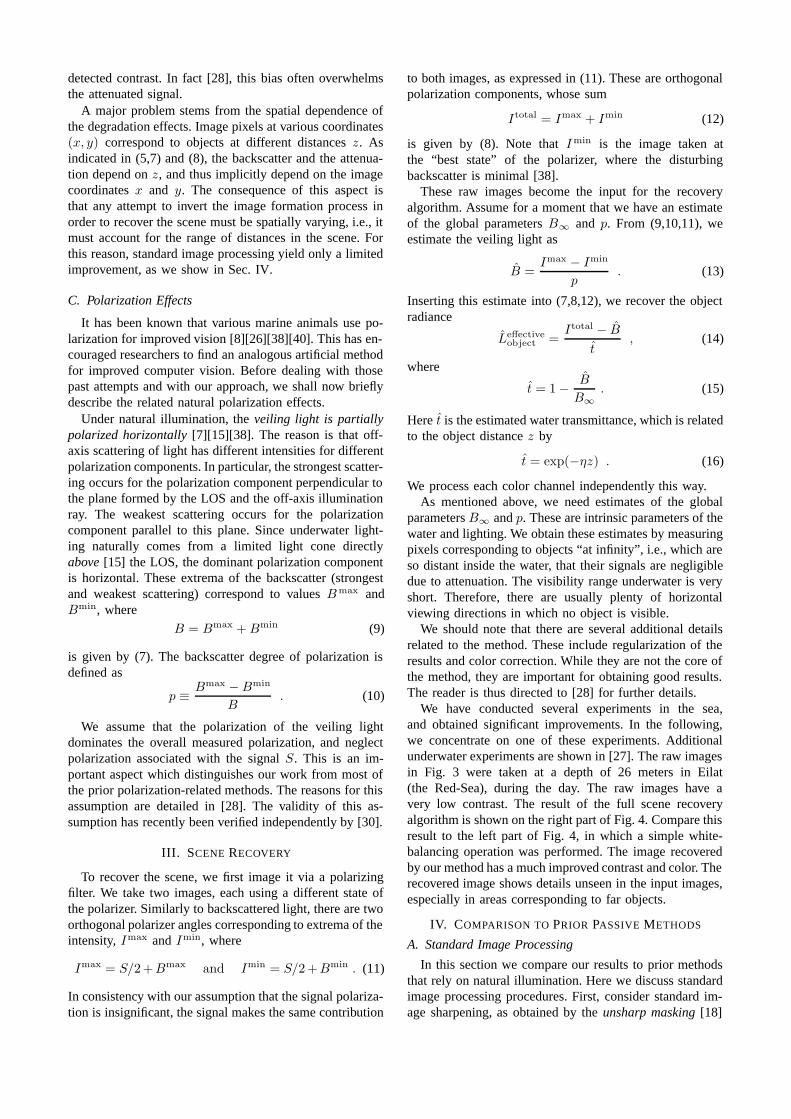
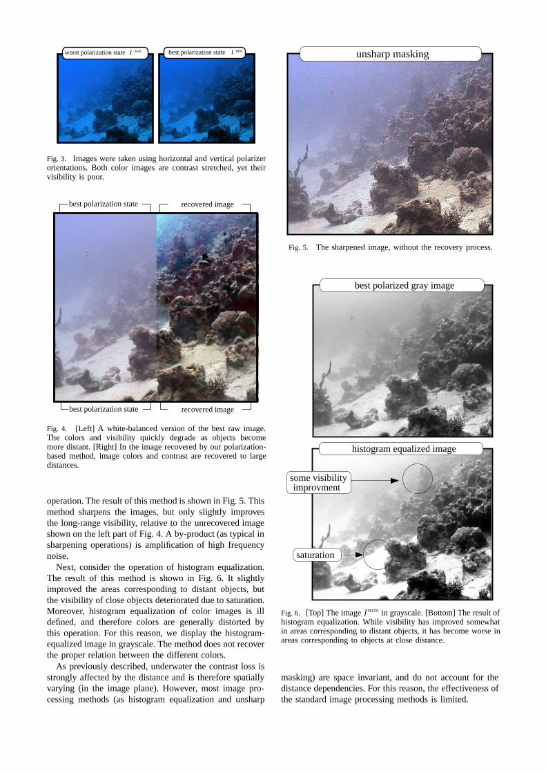
We have conducted several experiments in the sea,and obtained significant improvements. In the following,we concentrate on one of these experiments. Additionalunderwater experiments are shown in [27]. The raw imagesin Fig. 3 were taken at a depth of 26 meters in Eilat(the Red-Sea), during the day. The raw images have avery low contrast. The result of the full scene recoveryalgorithm is shown on the right part of Fig. 4. Compare thisresult to the left part of Fig. 4, in which a simple white-balancing operation was performed. The image recoveredby our method has a much improved contrast and color. Therecovered image shows details unseen in the input images,especially in areas corresponding to far objects.
IV. COMPARISON TO PRIOR PASSIVE METHODS
A. Standard Image Processing
In this section we compare our results to prior methodsthat rely on natural illumination. Here we discuss standardimage processing procedures. First, consider standard im-age sharpening, as obtained by the unsharp masking [18]
minmax best polarization stateworst polarization state II
Fig. 3. Images were taken using horizontal and vertical polarizerorientations. Both color images are contrast stretched, yet theirvisibility is poor.
best polarization state recovered image
best polarization state recovered image
Fig. 4. [Left] A white-balanced version of the best raw image.The colors and visibility quickly degrade as objects becomemore distant. [Right] In the image recovered by our polarization-based method, image colors and contrast are recovered to largedistances.
operation. The result of this method is shown in Fig. 5. Thismethod sharpens the images, but only slightly improvesthe long-range visibility, relative to the unrecovered imageshown on the left part of Fig. 4. A by-product (as typical insharpening operations) is amplification of high frequencynoise.
Next, consider the operation of histogram equalization.The result of this method is shown in Fig. 6. It slightlyimproved the areas corresponding to distant objects, butthe visibility of close objects deteriorated due to saturation.Moreover, histogram equalization of color images is illdefined, and therefore colors are generally distorted bythis operation. For this reason, we display the histogram-equalized image in grayscale. The method does not recoverthe proper relation between the different colors.
As previously described, underwater the contrast loss isstrongly affected by the distance and is therefore spatiallyvarying (in the image plane). However, most image pro-cessing methods (as histogram equalization and unsharp
unsharp masking
Fig. 5. The sharpened image, without the recovery process.
best polarized gray image
histogram equalized image
saturation
some visibilityimprovment
Fig. 6. [Top] The image Imin in grayscale. [Bottom] The result ofhistogram equalization. While visibility has improved somewhatin areas corresponding to distant objects, it has become worse inareas corresponding to objects at close distance.
masking) are space invariant, and do not account for thedistance dependencies. For this reason, the effectiveness ofthe standard image processing methods is limited.
No
visibility
degree of polarization
polarization difference imaging
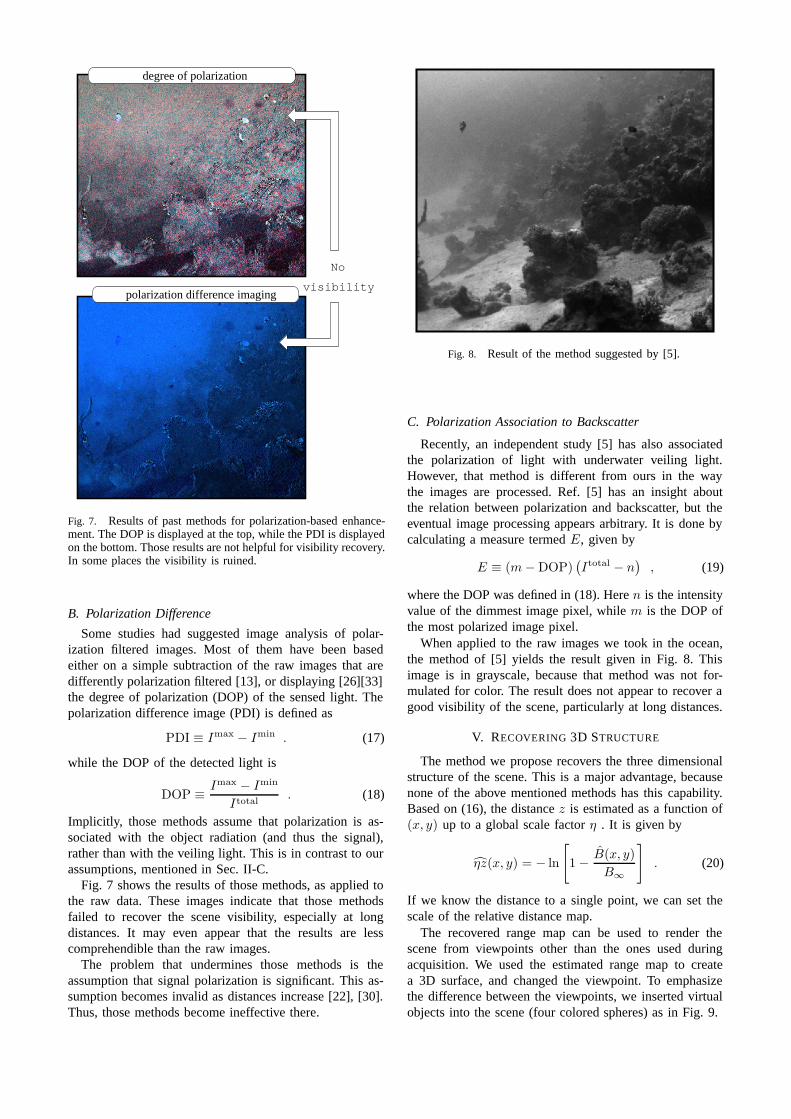
Fig. 7. Results of past methods for polarization-based enhance-ment. The DOP is displayed at the top, while the PDI is displayedon the bottom. Those results are not helpful for visibility recovery.In some places the visibility is ruined.
B. Polarization Difference
Some studies had suggested image analysis of polar-ization filtered images. Most of them have been basedeither on a simple subtraction of the raw images that aredifferently polarization filtered [13], or displaying [26][33]the degree of polarization (DOP) of the sensed light. Thepolarization difference image (PDI) is defined as
PDI ≡ Imax − Imin . (17)
while the DOP of the detected light is
DOP ≡ Imax − Imin
Itotal. (18)
Implicitly, those methods assume that polarization is as-sociated with the object radiation (and thus the signal),rather than with the veiling light. This is in contrast to ourassumptions, mentioned in Sec. II-C.
Fig. 7 shows the results of those methods, as applied tothe raw data. These images indicate that those methodsfailed to recover the scene visibility, especially at longdistances. It may even appear that the results are lesscomprehendible than the raw images.
The problem that undermines those methods is theassumption that signal polarization is significant. This as-sumption becomes invalid as distances increase [22], [30].Thus, those methods become ineffective there.
Fig. 8. Result of the method suggested by [5].
C. Polarization Association to Backscatter
Recently, an independent study [5] has also associatedthe polarization of light with underwater veiling light.However, that method is different from ours in the waythe images are processed. Ref. [5] has an insight aboutthe relation between polarization and backscatter, but theeventual image processing appears arbitrary. It is done bycalculating a measure termed E, given by
E ≡ (m − DOP)(Itotal − n
), (19)
where the DOP was defined in (18). Here n is the intensityvalue of the dimmest image pixel, while m is the DOP ofthe most polarized image pixel.
When applied to the raw images we took in the ocean,the method of [5] yields the result given in Fig. 8. Thisimage is in grayscale, because that method was not for-mulated for color. The result does not appear to recover agood visibility of the scene, particularly at long distances.
V. RECOVERING 3D STRUCTURE
The method we propose recovers the three dimensionalstructure of the scene. This is a major advantage, becausenone of the above mentioned methods has this capability.Based on (16), the distance z is estimated as a function of(x, y) up to a global scale factor η . It is given by
ηz(x, y) = − ln
[1 − B(x, y)
B∞
]. (20)
If we know the distance to a single point, we can set thescale of the relative distance map.
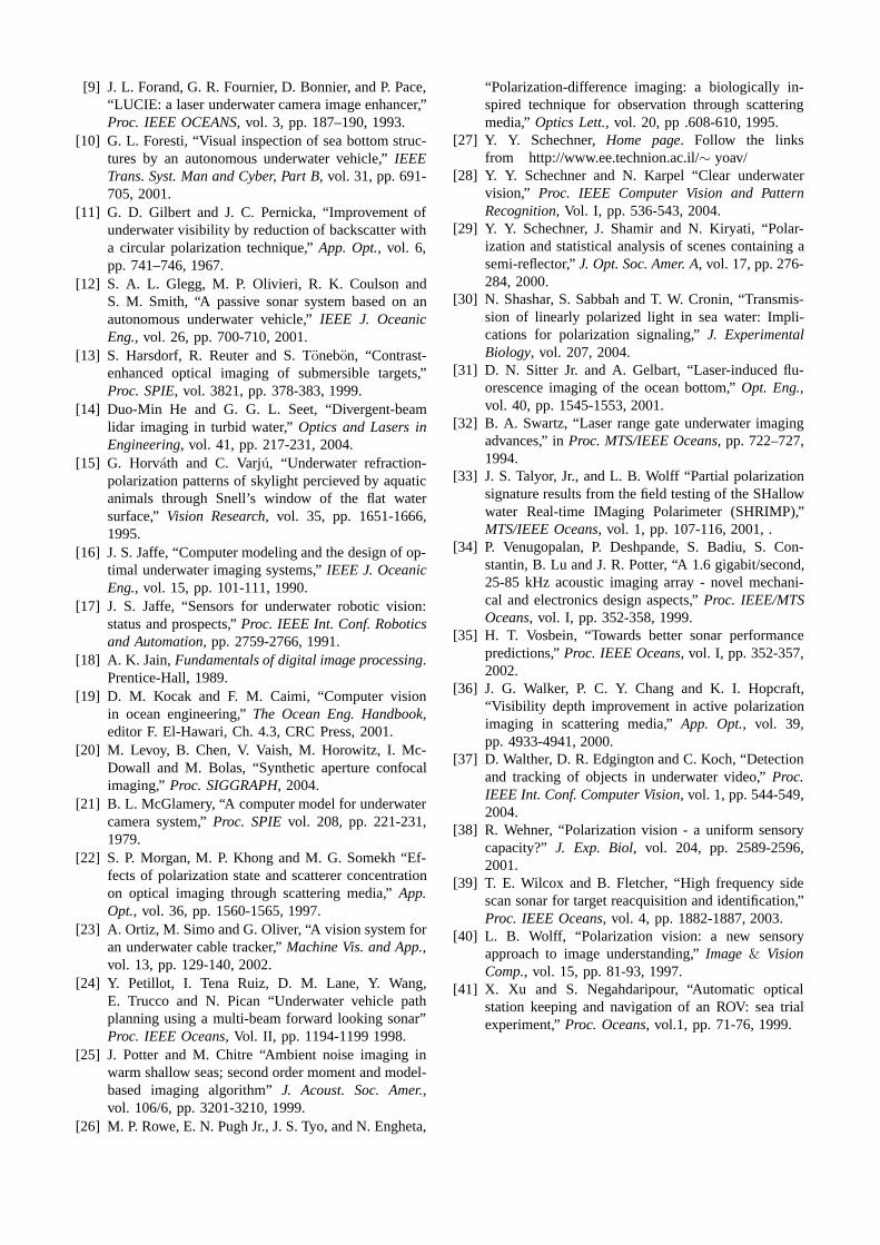
The recovered range map can be used to render thescene from viewpoints other than the ones used duringacquisition. We used the estimated range map to createa 3D surface, and changed the viewpoint. To emphasizethe difference between the viewpoints, we inserted virtualobjects into the scene (four colored spheres) as in Fig. 9.
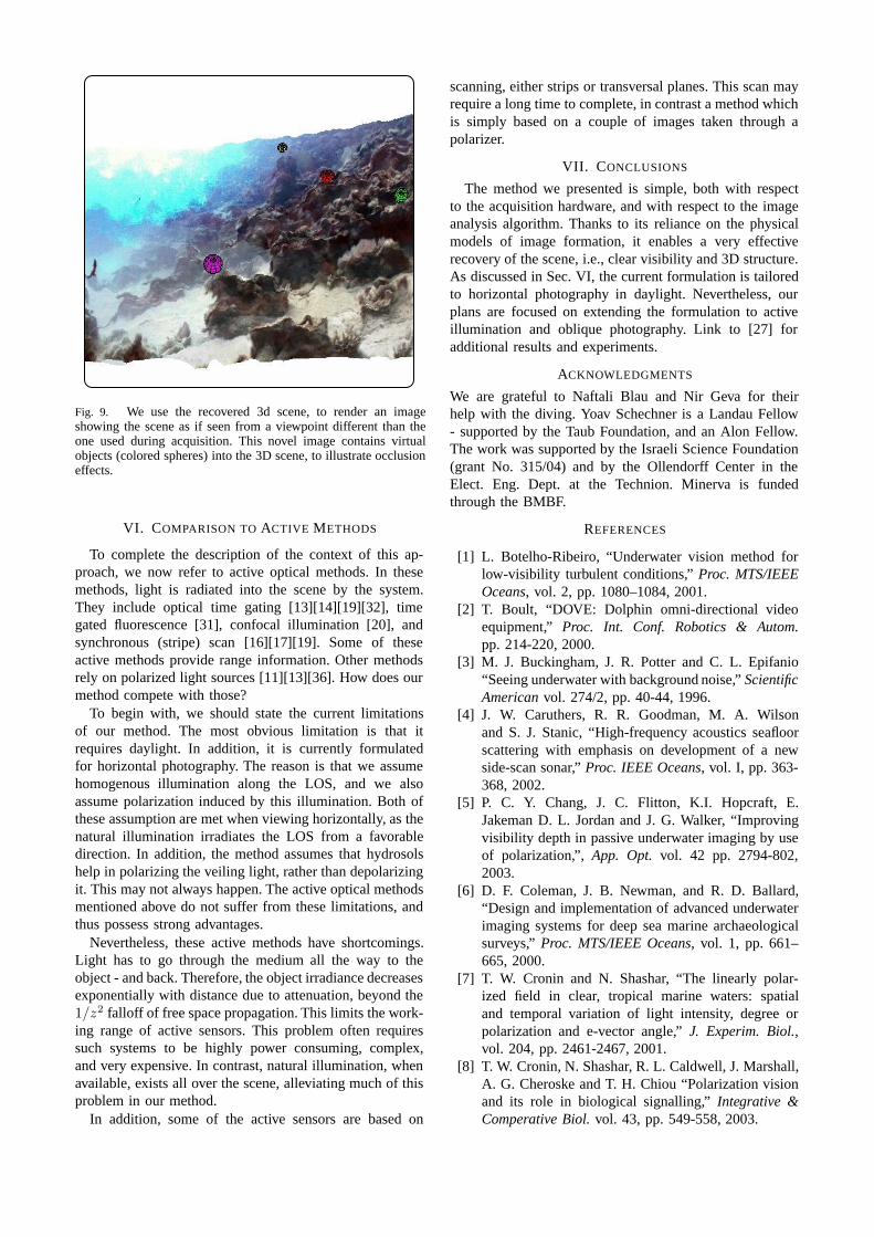
Fig. 9. We use the recovered 3d scene, to render an imageshowing the scene as if seen from a viewpoint different than theone used during acquisition. This novel image contains virtualobjects (colored spheres) into the 3D scene, to illustrate occlusioneffects.
VI. COMPARISON TO ACTIVE METHODS
To complete the description of the context of this ap-proach, we now refer to active optical methods. In thesemethods, light is radiated into the scene by the system.They include optical time gating [13][14][19][32], timegated fluorescence [31], confocal illumination [20], andsynchronous (stripe) scan [16][17][19]. Some of theseactive methods provide range information. Other methodsrely on polarized light sources [11][13][36]. How does ourmethod compete with those?
To begin with, we should state the current limitationsof our method. The most obvious limitation is that itrequires daylight. In addition, it is currently formulatedfor horizontal photography. The reason is that we assumehomogenous illumination along the LOS, and we alsoassume polarization induced by this illumination. Both ofthese assumption are met when viewing horizontally, as thenatural illumination irradiates the LOS from a favorabledirection. In addition, the method assumes that hydrosolshelp in polarizing the veiling light, rather than depolarizingit. This may not always happen. The active optical methodsmentioned above do not suffer from these limitations, andthus possess strong advantages.
Nevertheless, these active methods have shortcomings.Light has to go through the medium all the way to theobject - and back. Therefore, the object irradiance decreasesexponentially with distance due to attenuation, beyond the1/z2 falloff of free space propagation. This limits the work-ing range of active sensors. This problem often requiressuch systems to be highly power consuming, complex,and very expensive. In contrast, natural illumination, whenavailable, exists all over the scene, alleviating much of thisproblem in our method.
In addition, some of the active sensors are based on
scanning, either strips or transversal planes. This scan mayrequire a long time to complete, in contrast a method whichis simply based on a couple of images taken through apolarizer.
VII. CONCLUSIONS
The method we presented is simple, both with respectto the acquisition hardware, and with respect to the imageanalysis algorithm. Thanks to its reliance on the physicalmodels of image formation, it enables a very effectiverecovery of the scene, i.e., clear visibility and 3D structure.As discussed in Sec. VI, the current formulation is tailoredto horizontal photography in daylight. Nevertheless, ourplans are focused on extending the formulation to activeillumination and oblique photography. Link to [27] foradditional results and experiments.
ACKNOWLEDGMENTS
We are grateful to Naftali Blau and Nir Geva for theirhelp with the diving. Yoav Schechner is a Landau Fellow- supported by the Taub Foundation, and an Alon Fellow.The work was supported by the Israeli Science Foundation(grant No. 315/04) and by the Ollendorff Center in theElect. Eng. Dept. at the Technion. Minerva is fundedthrough the BMBF.
REFERENCES
[1] L. Botelho-Ribeiro, “Underwater vision method forlow-visibility turbulent conditions,” Proc. MTS/IEEEOceans, vol. 2, pp. 1080–1084, 2001.
[2] T. Boult, “DOVE: Dolphin omni-directional videoequipment,” Proc. Int. Conf. Robotics & Autom.pp. 214-220, 2000.
[3] M. J. Buckingham, J. R. Potter and C. L. Epifanio“Seeing underwater with background noise,” ScientificAmerican vol. 274/2, pp. 40-44, 1996.
[4] J. W. Caruthers, R. R. Goodman, M. A. Wilsonand S. J. Stanic, “High-frequency acoustics seafloorscattering with emphasis on development of a newside-scan sonar,” Proc. IEEE Oceans, vol. I, pp. 363-368, 2002.
[5] P. C. Y. Chang, J. C. Flitton, K.I. Hopcraft, E.Jakeman D. L. Jordan and J. G. Walker, “Improvingvisibility depth in passive underwater imaging by useof polarization,”, App. Opt. vol. 42 pp. 2794-802,2003.
[6] D. F. Coleman, J. B. Newman, and R. D. Ballard,“Design and implementation of advanced underwaterimaging systems for deep sea marine archaeologicalsurveys,” Proc. MTS/IEEE Oceans, vol. 1, pp. 661–665, 2000.
[7] T. W. Cronin and N. Shashar, “The linearly polar-ized field in clear, tropical marine waters: spatialand temporal variation of light intensity, degree orpolarization and e-vector angle,” J. Experim. Biol.,vol. 204, pp. 2461-2467, 2001.
[8] T. W. Cronin, N. Shashar, R. L. Caldwell, J. Marshall,A. G. Cheroske and T. H. Chiou “Polarization visionand its role in biological signalling,” Integrative &Comperative Biol. vol. 43, pp. 549-558, 2003.
[9] J. L. Forand, G. R. Fournier, D. Bonnier, and P. Pace,“LUCIE: a laser underwater camera image enhancer,”Proc. IEEE OCEANS, vol. 3, pp. 187–190, 1993.
[10] G. L. Foresti, “Visual inspection of sea bottom struc-tures by an autonomous underwater vehicle,” IEEETrans. Syst. Man and Cyber, Part B, vol. 31, pp. 691-705, 2001.
[11] G. D. Gilbert and J. C. Pernicka, “Improvement ofunderwater visibility by reduction of backscatter witha circular polarization technique,” App. Opt., vol. 6,pp. 741–746, 1967.
[12] S. A. L. Glegg, M. P. Olivieri, R. K. Coulson andS. M. Smith, “A passive sonar system based on anautonomous underwater vehicle,” IEEE J. OceanicEng., vol. 26, pp. 700-710, 2001.
[13] S. Harsdorf, R. Reuter and S. Tonebon, “Contrast-enhanced optical imaging of submersible targets,”Proc. SPIE, vol. 3821, pp. 378-383, 1999.
[14] Duo-Min He and G. G. L. Seet, “Divergent-beamlidar imaging in turbid water,” Optics and Lasers inEngineering, vol. 41, pp. 217-231, 2004.
[15] G. Horvath and C. Varju, “Underwater refraction-polarization patterns of skylight percieved by aquaticanimals through Snell’s window of the flat watersurface,” Vision Research, vol. 35, pp. 1651-1666,1995.
[16] J. S. Jaffe, “Computer modeling and the design of op-timal underwater imaging systems,” IEEE J. OceanicEng., vol. 15, pp. 101-111, 1990.
[17] J. S. Jaffe, “Sensors for underwater robotic vision:status and prospects,” Proc. IEEE Int. Conf. Roboticsand Automation, pp. 2759-2766, 1991.
[18] A. K. Jain, Fundamentals of digital image processing.Prentice-Hall, 1989.
[19] D. M. Kocak and F. M. Caimi, “Computer visionin ocean engineering,” The Ocean Eng. Handbook,editor F. El-Hawari, Ch. 4.3, CRC Press, 2001.
[20] M. Levoy, B. Chen, V. Vaish, M. Horowitz, I. Mc-Dowall and M. Bolas, “Synthetic aperture confocalimaging,” Proc. SIGGRAPH, 2004.
[21] B. L. McGlamery, “A computer model for underwatercamera system,” Proc. SPIE vol. 208, pp. 221-231,1979.
[22] S. P. Morgan, M. P. Khong and M. G. Somekh “Ef-fects of polarization state and scatterer concentrationon optical imaging through scattering media,” App.Opt., vol. 36, pp. 1560-1565, 1997.
[23] A. Ortiz, M. Simo and G. Oliver, “A vision system foran underwater cable tracker,” Machine Vis. and App.,vol. 13, pp. 129-140, 2002.
[24] Y. Petillot, I. Tena Ruiz, D. M. Lane, Y. Wang,E. Trucco and N. Pican “Underwater vehicle pathplanning using a multi-beam forward looking sonar”Proc. IEEE Oceans, Vol. II, pp. 1194-1199 1998.
[25] J. Potter and M. Chitre “Ambient noise imaging inwarm shallow seas; second order moment and model-based imaging algorithm” J. Acoust. Soc. Amer.,vol. 106/6, pp. 3201-3210, 1999.
[26] M. P. Rowe, E. N. Pugh Jr., J. S. Tyo, and N. Engheta,
“Polarization-difference imaging: a biologically in-spired technique for observation through scatteringmedia,” Optics Lett., vol. 20, pp .608-610, 1995.
[27] Y. Y. Schechner, Home page. Follow the linksfrom http://www.ee.technion.ac.il/∼ yoav/
[28] Y. Y. Schechner and N. Karpel “Clear underwatervision,” Proc. IEEE Computer Vision and PatternRecognition, Vol. I, pp. 536-543, 2004.
[29] Y. Y. Schechner, J. Shamir and N. Kiryati, “Polar-ization and statistical analysis of scenes containing asemi-reflector,” J. Opt. Soc. Amer. A, vol. 17, pp. 276-284, 2000.
[30] N. Shashar, S. Sabbah and T. W. Cronin, “Transmis-sion of linearly polarized light in sea water: Impli-cations for polarization signaling,” J. ExperimentalBiology, vol. 207, 2004.
[31] D. N. Sitter Jr. and A. Gelbart, “Laser-induced flu-orescence imaging of the ocean bottom,” Opt. Eng.,vol. 40, pp. 1545-1553, 2001.
[32] B. A. Swartz, “Laser range gate underwater imagingadvances,” in Proc. MTS/IEEE Oceans, pp. 722–727,1994.
[33] J. S. Talyor, Jr., and L. B. Wolff “Partial polarizationsignature results from the field testing of the SHallowwater Real-time IMaging Polarimeter (SHRIMP),”MTS/IEEE Oceans, vol. 1, pp. 107-116, 2001, .
[34] P. Venugopalan, P. Deshpande, S. Badiu, S. Con-stantin, B. Lu and J. R. Potter, “A 1.6 gigabit/second,25-85 kHz acoustic imaging array - novel mechani-cal and electronics design aspects,” Proc. IEEE/MTSOceans, vol. I, pp. 352-358, 1999.
[35] H. T. Vosbein, “Towards better sonar performancepredictions,” Proc. IEEE Oceans, vol. I, pp. 352-357,2002.
[36] J. G. Walker, P. C. Y. Chang and K. I. Hopcraft,“Visibility depth improvement in active polarizationimaging in scattering media,” App. Opt., vol. 39,pp. 4933-4941, 2000.
[37] D. Walther, D. R. Edgington and C. Koch, “Detectionand tracking of objects in underwater video,” Proc.IEEE Int. Conf. Computer Vision, vol. 1, pp. 544-549,2004.
[38] R. Wehner, “Polarization vision - a uniform sensorycapacity?” J. Exp. Biol, vol. 204, pp. 2589-2596,2001.
[39] T. E. Wilcox and B. Fletcher, “High frequency sidescan sonar for target reacquisition and identification,”Proc. IEEE Oceans, vol. 4, pp. 1882-1887, 2003.
[40] L. B. Wolff, “Polarization vision: a new sensoryapproach to image understanding,” Image & VisionComp., vol. 15, pp. 81-93, 1997.
[41] X. Xu and S. Negahdaripour, “Automatic opticalstation keeping and navigation of an ROV: sea trialexperiment,” Proc. Oceans, vol.1, pp. 71-76, 1999.