Recommended Practices for CFD modelsoss.jishulink.com/caenet/forums/upload/2013/04/18/380/... ·...
63
v.13.2.2
Transcript of Recommended Practices for CFD modelsoss.jishulink.com/caenet/forums/upload/2013/04/18/380/... ·...

v.13.2.2

ANSA v.13.2.2 ANSA for CFD Quick Start Guide
Table of Contents
1. Introduction............................................................................................................................................ 5
1.1. Customizing ANSA..........................................................................................................................7 1.2. Basic terminology............................................................................................................................ 8 1.3. View Control................................................................................................................................... 9 1.4. Detail on Demand effect...............................................................................................................10 1.5. Most important key actions...........................................................................................................10 1.6. Making Selections........................................................................................................................ 11 1.7. TOPO menu................................................................................................................................. 12 1.8. MESH menu................................................................................................................................. 13 1.9. DECK menu.................................................................................................................................. 14 1.10. MORPH menu............................................................................................................................ 15 1.11. HEXABLOCK menu.................................................................................................................... 16
2. Geometry Preparation......................................................................................................................... 17
2.1. Data Input...................................................................................................................................... 17 2.2. Resolution and Tolerances............................................................................................................17 2.3. Geometry Clean up....................................................................................................................... 18 2.4. Outer or middle surface extraction.................................................................................................19 2.5. Watertight preparation................................................................................................................... 20 2.6. Checking for intersections and proximities at Geometry level.......................................................20 2.7. Creation of sub-volumes................................................................................................................20 2.8. Model organization........................................................................................................................ 21 2.9. Detection of Baffles....................................................................................................................... 22 2.10. Link Geometry............................................................................................................................. 23 2.11. Treating Surfaces........................................................................................................................ 24
3. Surface Meshing................................................................................................................................... 25
3.1. Simplifying Macros........................................................................................................................ 25 3.2. Uniform size mesh......................................................................................................................... 26 3.3. Variable feature dependent size mesh..........................................................................................26 3.4. STL like mesh................................................................................................................................ 30 3.5. Summary of Automatic Quality Improvement functions.................................................................31 3.6. Useful Checks............................................................................................................................... 32
4. Layers.................................................................................................................................................. 33
5. Surface Wrapping................................................................................................................................ 35
5.1. Variable size wrapping.................................................................................................................. 36 5.2. Preparation for wrapping...............................................................................................................37 5.3. Post-wrap checks.......................................................................................................................... 37
6. Identifying leaks................................................................................................................................... 38
6.1. Leak check on dirty meshes for wrapping.....................................................................................38 6.2. Leak check on good quality shell mesh.........................................................................................40
7. Volume Meshing.................................................................................................................................. 41
7.1. Manual Volume Definition..............................................................................................................41 7.2. DETECT functionality for Volume Definition..................................................................................41 7.3. Meshing the Volume...................................................................................................................... 42 7.4. Checking the Volume quality and fixing.........................................................................................43
8. Batch Meshing..................................................................................................................................... 43
9. CFD interfaces..................................................................................................................................... 44
10. Model generation Checklist................................................................................................................46
BETA CAE Systems S.A. 2

ANSA v.13.2.2 ANSA for CFD Quick Start Guide
11. Morphing for CFD.............................................................................................................................. 48
11.1. Box Morphing Approach..............................................................................................................48 11.2. BOX preparation.......................................................................................................................... 49 11.3. Box shape issues........................................................................................................................ 51 11.4. Box boundaries ........................................................................................................................... 51 11.5. Larger Boxes maintain orthogonality...........................................................................................52 11.6. Large Boxes result in smaller deformations of the volume mesh.................................................52 11.7. Tangency condition..................................................................................................................... 53 11.8. Additional User Tangency condition............................................................................................54 11.9. Tolerances................................................................................................................................... 55 11.10. Edge fitting on features of the model.........................................................................................55 11.11. Troubleshooting morphing boxes..............................................................................................57 11.12. Direct Morphing (without morphing boxes)................................................................................58 11.13. Define MORPH Parameters......................................................................................................59 11.14. The Deformation Morph Parameter...........................................................................................59 11.15. Morph the geometry through deformation mapping...................................................................60 11.16. Part Manager structure..............................................................................................................62
12. User Defined Functions for CFD models...........................................................................................63
COPYRIGHT 1990-2012 BETA CAE SYSTEMS S.A.ALL RIGHTS RESERVED.
BETA CAE Systems S.A.Kato Scholari, Thessaloniki,GR-57500 Epanomi,GreeceTel: +30-2392 021420 +30 2311 993300Fax: +30-2392 021828E-mail: [email protected]: http://www.beta-cae.gr
BETA CAE Systems S.A. 3
ANSA v.13.2.2 ANSA for CFD Quick Start Guide
1. Introduction
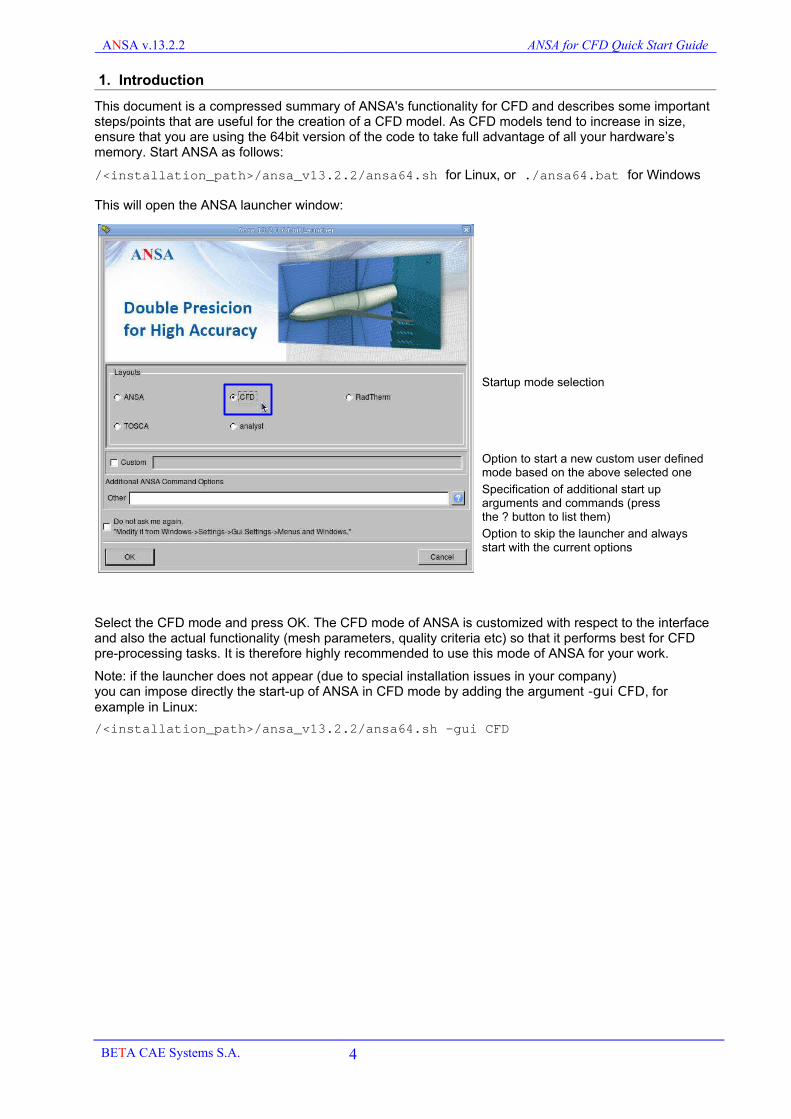
This document is a compressed summary of ANSA's functionality for CFD and describes some important steps/points that are useful for the creation of a CFD model. As CFD models tend to increase in size, ensure that you are using the 64bit version of the code to take full advantage of all your hardware’s memory. Start ANSA as follows:
/<installation_path>/ansa_v13.2.2/ansa64.sh for Linux, or ./ansa64.bat for Windows
This will open the ANSA launcher window:
Startup mode selection
Option to start a new custom user defined mode based on the above selected one
Specification of additional start up arguments and commands (pressthe ? button to list them)
Option to skip the launcher and always start with the current options
Select the CFD mode and press OK. The CFD mode of ANSA is customized with respect to the interface and also the actual functionality (mesh parameters, quality criteria etc) so that it performs best for CFD pre-processing tasks. It is therefore highly recommended to use this mode of ANSA for your work.
Note: if the launcher does not appear (due to special installation issues in your company)you can impose directly the start-up of ANSA in CFD mode by adding the argument -gui CFD, for example in Linux:
/<installation_path>/ansa_v13.2.2/ansa64.sh -gui CFD
BETA CAE Systems S.A. 4

ANSA v.13.2.2 ANSA for CFD Quick Start Guide
This will ensure that ANSA starts with a default interface tuned for CFD preprocessing, as shown below:
Note that this customization does not refer only to the interface and button positions, but also to all tuning parameters that affect the algorithms and performance of the software for the common CFD tasks!
1. Access to Help: html Online-Help and all PDF documentation. 2. Access to:
Batch Mesh for meshing automationPart Manager for model organization through Groups, sub-assemblies and PartsPIDs for management of Properties of the modelSETs for managemrnt of SET (groups of ANSA entities like elements, properties, Faces etc)Database Browser for access to the contents of the Database and Filters for model managementMesh Parameters for controlling the meshing algorithms and quality improvementQuality Criteria for setting quality criteria and threshold values and settings Presentation ParametersMeasure tool to make measurements of the modelSettings for settings and customization for Functionality and GUI, correspondingly saved in CFD.defaults and CFD.xml files in your home directory under <homedir>/.BETA/ANSA/version_v13.2.2/
3. Switch between the main menus ofTOPO for geometry creation, manipulation, cleanup and watertight preparationMESH for surface and volume mesh and fixDECK for solver related features and the creation of Size Boxes for controlling mesh sizeMORPH for mesh and geometry morphingHEXABLOCK for hexa meshing based on block structure of boxes
4. The functions are arranged in Groups, depending on the Entity that they are applicable to. Some additional functions that may exist in the buffer menu (hidden) can be accessed by clicking on the Group Name with the left mouse button.5. The Options window displays all the settings of the currently Active function. 6. These flag buttons control the visibility mode of the model, in the form of flags or toggle buttons like coloring the model in ENT (Entity) or PID (Property ID), or SHADOW or WIRE mode etc. In addition, there are visibility flag buttons for different Entities.7. Access to Transformations (translate, copy, move etc), model Checks and Information.8. The FOCUS group contains all the functions that are used to isolate and control the visibility of selected entities in order to obtain a clear image of the working area of the model.9. Instructions and reporting of the program are printed in the message line and the ANSA info window.
BETA CAE Systems S.A. 5
1. Access to Help2. Access to:-Batch mesh-Part Manager-PID list-SET list-Database browser-Mesh Parameters-Quality Criteria-Measure tool-Settings
8. FOCUS commands
7. Geometry and D.UTIL Groups 6. View
modes
3. MENUbuttons
4. Group of Functions
9.Message line and ANSA Info window
5. Options window
Group Name

ANSA v.13.2.2 ANSA for CFD Quick Start Guide
1.1. Customizing ANSA
The CFD mode is the best starting point of ANSA for CFD. This does not mean that you cannot change it of course according to your specific needs or preferences.You can make any change in the functionality settings (default solver, quality criteria, meshing parameters etc) or the GUI settings (button positions, colors, window sizes etc)and then save them through the Settings window:
At the bottom left there are two groups of buttons:
Save settings: save all functionality related settings in CFD.defaults fileandSave GUI settings: save all GUI settings in CFD.xml file
Save Settings and Save GUI Settings will save in your home directory, in a hidden folder called .BETA your customized settings (in the files CFD.defaults and CFD.xml) as shown below for every ANSA version:
The ANSA_TRANSL file is a file that contains user defined script functions (see section 12)CFD.defaults contains all your customized functionality settingsCFD.xml contains all your customized GUI settingsThe launcher.txt file contains the last used settings of the ANSA launcher window
Next time you start ANSA, these customized settings will be read and applied.Note that these customized settings are very important as they affect not just the appearance of the software but also its functionality. If for whatever reason you are in doubt about these local settings, you may remove them from this location and then ANSA will start again with the default startup CFD mode.
BETA CAE Systems S.A. 6

ANSA v.13.2.2 ANSA for CFD Quick Start Guide
1.2. Basic terminology
In the TOPO menu the following entities appear:
The Surface is the underlying mathematical CAD description of the Face where the actual mesh takes place. The CONS (Curves ON Surfaces) are the boundaries of the Faces. According to their connectivity, they are colored in Red (single edge), Yellow (double connectivity) or Cyan (triple of more connectivity). The Hot Points are the end points of CONS. 3D Curves are curves in space that are used for CAD constructions, but they are not connected to the Faces. 3D Points are also used for geometrical constructions.
Correspondingly, in the MESH and DECK menus:
A Macro Area can consist of one or more joined Faces. The Perimeters are the boundaries of the Macro Areas. The Hot Points are the end points of the Perimeters. FE-model mesh is mesh that is not associated to geometry (dead-mesh). Finally, a yellow Connecting Spot indicates connectivity of a Macro area with FE-model mesh.
BETA CAE Systems S.A. 7
Surface
3D Curve
Face
SingleCONS
DoubleCONS
TripleCONS
Weld Spot
Connecting SpotFE-model elements
Hot Point
Cross hatch
Perimeter Segment
Perimeter NodeWeld Spot
Connecting Spot FE-model elements
Hot Point
MacroArea
3D Point

ANSA v.13.2.2 ANSA for CFD Quick Start Guide
1.3. View ControlBasic view control can be achieved with the mouse:
Rotate
With the Ctrl key pressed, rotate the model with the left mouse button.
Note that with Ctrl+Shift pressed, you get dynamic mode rotation (automatically Shadow mode and other details become de-activated for faster view manipulation!).
Translate
With the Ctrl key pressed, translate the model with the middle mouse button.
Zoom
With the Ctrl button pressed, zoom in and out pressing both left and middle mouse buttons.
Moving the mouse left and down the view zooms in and moving right and up the view zooms out.
You can also zoom in and out by using the mouse wheel.
View control is also possible using the Function keys of the keyboard:
TOP FRONT LEFT BOTTOM BACK RIGHT ZOOM INZOOM OUT
ZOOM ALL
Default View
BETA CAE Systems S.A. 8
Ctrl
Ctrl
Ctrl
F1 F4F2 F3 F5 F6 F7 F8 F9 F10

ANSA v.13.2.2 ANSA for CFD Quick Start Guide
1.4. Detail on Demand effectBy default, the visible details of a model vary with the current zoom level. This means when you view a model from far, less detail is displayed (for example you cannot see the WIRE of the mesh). As you zoom in, you begin to see more and more details like the mesh wireframe.
The magnitude of this effect, called detail on demand, is controlled by the Quality window (F11 key), Presentation Parameters tab with
the slide bar shown on the left.
1.5. Most important key actionsThe mouse buttons are mainly used as follows:
The left mouse button (1):- to activate menu buttons- to select or define entities
The middle mouse button (2):- to confirm selections or processes
The right mouse button (3):- to perform the opposite action of left mouse button (e.g. select/deselect or insert/delete)- to reapply last action to other entities
The ESC key cancels operations, exits from functions and closes windows at any step of the process. So if you are in doubt, press ESC.
The Pause/Break key can be used to interrupt a function while it is running (for example aborts the SHADOW or Volume mesh process during its calculation, if this takes too long).
The F11 key gives access to the Quality and Presentation Parameters window. In this window the user can specify the quality criteria definitions and their threshold values, as well as other presentation attributes.
BETA CAE Systems S.A. 9
Esc
PauseBreak
F11
F11
Zoom outlow detail
Zoom inhigh detail
higher detail lower detail

ANSA v.13.2.2 ANSA for CFD Quick Start Guide
1.6. Making Selections
Selections are performed with left mouse button. Selected entities are highlighted in white and can be de-selected with right mouse button, if it is required.
Selections can be made in various ways: single entities, box selections, or feature selections.
By box selection, left click and drag to create a Box to select all entities in it.
In addition, when selection are required, the Feature Selection Assistant opens with some of the following options:
Selections can be made on different entities like Edges or Areas. A summary of the Feature Selection Assistant that appears in the main menu bar is shown below:
BETA CAE Systems S.A. 10
Feature Angle Selection PID Region Selection
Box selection
Loop: pick an edge to select a whole closed loop of edges, for example a hole
PID region: select a whole unconnected PID region by picking one element only (selection stops at triple cyan boundaries)

ANSA v.13.2.2 ANSA for CFD Quick Start Guide
1.7. TOPO menu
In this menu the user can create, modify and clean up geometry. The menu is divided in groups of functions according to the entities that they refer to.
HOT POINTsThese functions are used to create or delete Hot Points or Weld Spots
CONSFunctions that are applied on CONS (Curves ON Surfaces)
FACEsFunctions to create or modify Faces
SURFsFunctions that create Faces and modify Surfaces
CURVEsFunctions to create 3D Curves
POINTsFunctions to create 3D Points
AUXILIARIESFunctions to create Working Planes in order to draw in 2D mode
Options window
The available options of the currently active function appear in this window
BETA CAE Systems S.A. 11

ANSA v.13.2.2 ANSA for CFD Quick Start Guide
1.8. MESH menu
In the MESH menu the user can create, modify and fix surface and volume mesh.
HOT POINTsFunctions to insert or remove Hot Points or Weld Spots
PERIMETERsFunctions to assign Perimeter nodes
MACROsOperations to modify Macro Areas, manually or automatically, in order to improve their shape for better surface meshing
GRIDsManual operations on grids (move and paste)
MESH GEN.Surface meshing algorithms
SHELL MESHQuality improvement functions (Reshape, Recons, Smooth and Fix Qual) and other operations on surface mesh
ELEMENTsManual operations on elements andSurface Wrapping tool
VOLUMEsVolume definition, mesh generation and quality improvement functions for volume elements
Options List window
The available options of the currently active function appear in this window
BETA CAE Systems S.A. 12

ANSA v.13.2.2 ANSA for CFD Quick Start Guide
1.9. DECK menu
In the Deck menu the user can specify the Solver for which to prepare a model (etc. OpenFOAM, Fluent, Star etc). In addition, they can perform some operations on Grids, Coordinate Systems, Elements, or define Size Boxes for mesh size control, and setup solver controlsNODESFunctions to create, delete or disconnect nodes
COORD. SYSTEMSFunctions to create orthogonal, cylindrical or spherical coordinate systems
ELEMENTSFunctions to create manually individual line, shell and solid elements and renumber them
SIZE BOXESFunctions to create and manage Size Boxes in order to control the max element length of surface and volume mesh in specific regions of the model.
AUXILIARIESSetup solver controls (like the controlDict file for OpenFOAM)
BETA CAE Systems S.A. 13

ANSA v.13.2.2 ANSA for CFD Quick Start Guide
1.10. MORPH menu
In this menu the user can morph surface/volume mesh and geometry in order to modify and improve a design.
BOXES: Functions to create and manage Morphing Boxes
CONTROLS: Functions to define and manage Morphing Parameters
CONTROL POINTS: Functions to insert Control Points on Morphing Box edges in order to change their shape
EDGES: Functions that affect Morphing Box edges (like for example the control of Tangency on them)
HATCHES: Functions that work on Morphing Box faces (Hatches)
MODIFICATION: Movement of Control Points (with or without Morphing action, depending on the status of the Morphing field in the Options List window)
DIRECT MORPHING: Morphing without the need of Morphing Boxes (example the FIT and DFM functions)
CHECKS: troubleshooting checks for Morph Box morphing
DRAW MODE: visibility of Box Hatches andof Geometry in TOPO or MESH mode
Options List window:Morphing: The status of this field controls whether a control point movement, from the MODIFICATION group of functions, will Morph or not the model that is loaded in the Boxes!!
See section 10 for more details
BETA CAE Systems S.A. 14

ANSA v.13.2.2 ANSA for CFD Quick Start Guide
1.11. HEXABLOCK menu
In this menu the user can generate pure hexa meshes based on block topologies.
HEXA BOXES: Functions to create and manipulate Hexa Boxes
CONTROL POINTS: Functions to insert Control Points on Morphing Box edges in order to change their shape later on
ASSOCIATE BOXES: Functions to associate the Control Points, Edges and Faces of the Boxes on the actual model geometry, so that the mesh can be projected on the geometry
MODIFICATION: Functions to move specific Control Points in order to change the shape of the boxes
HEXA MESH: Functions to assign element length, number and spacing on the Box edges, and to generate the Volume and Surface meshes
VISIBILITY: control of visibility of Control Points, grid nodes on edges, associations, as well as TOPO or MESH view type, Display mode of Hatches of Boxes and of geometry
Options window
The available options of the currently active function appear in this window
BETA CAE Systems S.A. 15
ANSA v.13.2.2 ANSA for CFD Quick Start Guide
2. Geometry Preparation
2.1. Data Input
In ANSA you can read directly neutral CAD files (IGES, STEP, VDA), or you can use the CAD to ANSA translators (for Catia v4 and v5, Unigraphics, ProE and JT). In the latter approach, in addition to obtaining higher quality geometrical data, you can also translate and bring into ANSA information about Property name and ID, Part name and assembly structure of the model, etc., as designed in the CAD system. This additional information will help you to manage your model easier and also allows the ability to trace back a Part, if needed.When working with the neutral CAD files you can use the functionality of the ANSA_TRANSL and the ANSA scripting language to be able to automate some of the above (see ANSA User’s Guide).
2.2. Resolution and Tolerances
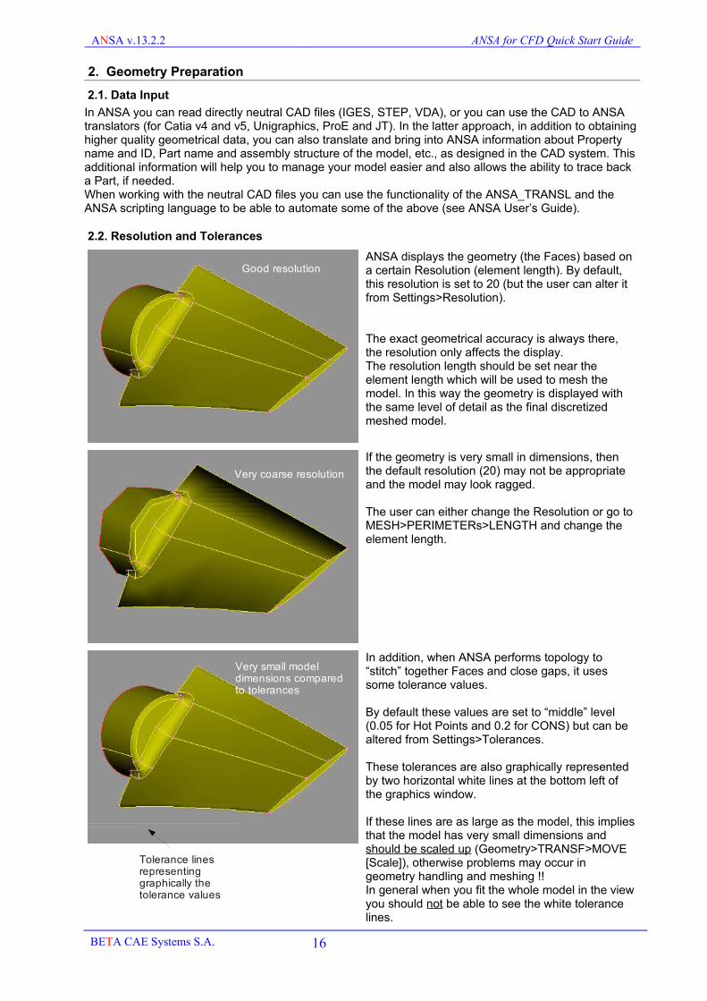
ANSA displays the geometry (the Faces) based on a certain Resolution (element length). By default, this resolution is set to 20 (but the user can alter it from Settings>Resolution).
The exact geometrical accuracy is always there, the resolution only affects the display.The resolution length should be set near the element length which will be used to mesh the model. In this way the geometry is displayed with the same level of detail as the final discretized meshed model.
If the geometry is very small in dimensions, then the default resolution (20) may not be appropriate and the model may look ragged.
The user can either change the Resolution or go to MESH>PERIMETERs>LENGTH and change the element length.
In addition, when ANSA performs topology to “stitch” together Faces and close gaps, it uses some tolerance values.
By default these values are set to “middle” level (0.05 for Hot Points and 0.2 for CONS) but can be altered from Settings>Tolerances.
These tolerances are also graphically represented by two horizontal white lines at the bottom left of the graphics window.
If these lines are as large as the model, this implies that the model has very small dimensions and should be scaled up (Geometry>TRANSF>MOVE [Scale]), otherwise problems may occur in geometry handling and meshing !!In general when you fit the whole model in the view you should not be able to see the white tolerance lines.
BETA CAE Systems S.A. 16
Good resolution
Very coarse resolution
Very small model dimensions comparedto tolerances
Tolerance lines representing graphically the tolerance values

ANSA v.13.2.2 ANSA for CFD Quick Start Guide
2.3. Geometry Clean up
When reading geometry in ANSA you should first check the topology.
You can refer to Tutorial “Basic ANSA” to follow the clean up steps of this model.
De-activate SHADOW and DOUBLE CONS visibility and see if there are any red or cyan CONS which indicate single or triple connectivity.Check if these features are intentional, or topological errors.
Use the TOPO functions to fix such problems
The final view should be like the one shown here.
Before switching to MESH, activate SHADOW and FOCUS>UNCHECKED. If ANSA leaves any Faces visible, it means that they cannot be shaded and you should fix them also.
You can also use the function CHECK>GEOMETRY to identify and fix automatically some problems.
BETA CAE Systems S.A. 17
Topological problems
No Topological problems

ANSA v.13.2.2 ANSA for CFD Quick Start Guide
2.4. Outer or middle surface extraction
If you start with solid description parts, you need to extract the outer (or middle) surface. Depending on the case, you should use one, or a combination, of the following approaches:
Pressed sheet metal Parts (clean geometry)
For pressed sheet metal parts that have no topological problems (gaps, red CONS) the FACEs>MID.SURF [SKIN] function can be used (see ANSA PDF User’s Guide).
Cast parts with triple connectivity
For parts that do not have fully clean and closed geometry or are not plain pressed sheet, but contain ribs and reinforcements, the SMID.SURF [SKIN] function cannot be used. Instead, the user can follow this workaround.Use the FOCUS commands OR and NOT with the feature angle selection active and a suitable angle value limit (you may have to increase the default angle to around 70). With this approach the file may contain gaps. The result is a simple outer surface extraction of one of the two sides.
Another option is to use the MID.SURF [CASTING] function. This will generate the middle skin of a complex cast part as shown below. This option is more calculation intensive than the SKIN option.
Note that the result of the MID.SURF [CASTING] function is a FE-model mesh.
Large bulkier assemblies (unclean geometry)
When you are dealing with large bulk parts (engine, transmission, exhaust box, interior passages of HVAC systems, etc.) you can use the ISOLATE [Skin] function (see ANSA User’s Guide).
You need to close the large openings and set a minimum length value equal to the smallest size detail you want to keep from the inside or the outside of the model.
BETA CAE Systems S.A. 18

ANSA v.13.2.2 ANSA for CFD Quick Start Guide
2.5. Watertight preparation
Having extracted the outer surfaces, you must create the watertight model by sealing all gaps and eliminating the overlaps. If these gaps are small (close to the Tolerances), they can be closed by TOPO or PASTE functions. If they exceed (by far) the tolerances, then new Faces must be created (usually with SURFs>COONS) to close them.
2.6. Checking for intersections and proximities at Geometry level
You should make some checks for intersection and proximity while constructing your model.First of all, use the CHECKs>PENETRATION [Intersections] to locate intersecting areas (wrong topology, misplaced parts etc). Fix these areas using TOPO functions (like FACEs>INTERSECT).Use the ISOLATE>FLANGES [Proximity] function to isolate Faces within a certain distance apart. This will indicate you all the proximity problem areas that may cause problems in volume meshing.Then use the FACEs>FUSE function to close these narrow proximity passages, where possible.
2.7. Creation of sub-volumes
Usually you need to create more than one volumes, either to allow different boundary conditions (porous and moving zones), or to be able to change only a part of the model and re-volume mesh only the area around it, or even for post-processing reasons.
When you create new Faces to define the sub-Volumes, remember to put them in PIDs that can be easily recognized by a name convention (say interior ) so that you can filter them easily in the PR.LIST. It is also a good idea to create a Part in the Part Manager, where you place all such interior faces.
BETA CAE Systems S.A. 19
ISOLATE [FLANGES GEOM] FACEs>FUSE

ANSA v.13.2.2 ANSA for CFD Quick Start Guide
2.8. Model organization
When you merge many ANSA databases in order to form your complete model, you may end up with many Parts and Groups in the Part Manager. It is worth to spend some time in the beginning, to arrange your model in proper Parts and Groups. This will help you later in meshing. Working only with the PR.LIST can be difficult, if you have a complicated model with say 200 Properties. The Part Manager can help you group your model in Parts and Groups and thus handle it more easily.
A good starting point in the Part Manager is to press Utilities>PID-PART. This will loose all current Parts and Groups structure and will place each PID in a separate Part at the top level of the tree.Then press Utilities>Remove Empty Parts>All to remove all now unused Parts and Groups Create new Groups from NEW>GROUP and place selected Parts in them.You can also use the NEW>GROUP from Visible, option (Move or Link). The Link option allows the reference of a Part in more than one Groups.
Having created the Group and Part structure of your model, you can focus on areas of your work more easily. For example, select a Group and right click for LOCK (you can lock more than one Group or Part). The Group is highlighted in yellow and from now on it is the only one that appears when you press FOCUS>ALL.
In case you have extracted your Part hierarchy structure of the assembly, exactly as created in the CAD system, you can use the double and parallel management system of Parts and Properties in ANSA. In the Part Manager you can retain your original Parts while the Properties you can assign them as you would want them to appear in the CFD solver.
BETA CAE Systems S.A. 20

ANSA v.13.2.2 ANSA for CFD Quick Start Guide
2.9. Detection of Baffles
In complicated models sometimes it is hard to identify if and where baffles (zero-thickness walls) are.
This can be done automatically using the function FOCUS>ISOLATE>Baffles
The model must be meshed and visible.
ANSA leaves on the screen only the baffles surface mesh.You can now easily assign the visible element to different PIDs using the User Defined Function ChangeBaffleProperties (see section 12).
BETA CAE Systems S.A. 21

ANSA v.13.2.2 ANSA for CFD Quick Start Guide
2.10. Link Geometry
Many CFD applications, especially external aero cases have geometries with similarities, like symmetry for example. In such cases it is possible to use the functionality of LINK Faces. This will save time in the meshing process as you will only have to do this on one side and the other will obtain the same mesh automatically.
A good starting point is the use of the FACEs>RM.DBL function which can search similar Faces and optionally replace them with LINK ones.
The replacing LINK Faces can be distinguished from the other by their light brown cross hatch color.
After replacement ensure that all Faces are topologically connected with the remaining geometries (along the symmetry plane and also with the underbody).
Use LINK geometry only on large similar Parts.
An underbody may contain several symmetric areas but these areas will also be mixed with non-symmetrical features.In these cases avoid the replacement of the symmetric Faces with LINK, as this will lead to irregular boundaries between LINK and non LINK Faces.
New LINK Faces can also be created with the GEOMETRY>TRANSF [LINK] function.
BETA CAE Systems S.A. 22

ANSA v.13.2.2 ANSA for CFD Quick Start Guide
2.11. Treating Surfaces
If the underlying Surface is a revolute of 360o, you may get unmeshed Macros.
Use the SURFs>BREAK function, so that ANSA splits it.
Use also the function SURFs>SHRINK if the underlying Surface is far larger than the actual Faces.
Sometimes the underlying Surfaces of Faces are too large.This may significantly delay some TOPO operations like project, intersect, meshing, etc.It is therefore recommended to treat such Faces as follows:
Use the SURFs>SHRINK function, select All Faces and confirm.
Activate the Per Face Flag.
Now the Surfaces of all Faces have been shrunk to their Face limits.
BETA CAE Systems S.A. 23

ANSA v.13.2.2 ANSA for CFD Quick Start Guide
3. Surface Meshing
The following sections describe some tips for surface meshing.
3.1. Simplifying Macros
The quality of the resulting mesh can be greatly improved by joining Macros together, prior to applying Perimeter lengths and spacing.
Joining Macros can be done manually using the function PERIMETERs>JOIN.
It can also be done automatically with the function MACROs>SIMPLIFY
!!! Before using the function ensure that correct element length has been applied either through PERIMETERs>LENGTH or SPACING, as the defeaturing that is performed depends on it.
Place the slidebar to the desired location (default middle location is recommended).
Press Run.
ANSA previews the Perimeters that are going to be joined.
Press OK to confirm the previewed joined Perimeters.
ANSA joins the Macros the Perimeters that do not form important features and should be removed.
Delete any remaining Hot Points and re-apply the correct Length or Spacing.
Larger Macros result in better flowing mesh.
Any manually (JOIN) or automatically (SIMPLIFY) joined Macros can be brought back to their original state using PERIMETERs>RELEASE.
BETA CAE Systems S.A. 24

ANSA v.13.2.2 ANSA for CFD Quick Start Guide
3.2. Uniform size mesh
In cases where you want a uniform size triangular mesh you must assign a PERIMETERs>LENGTH of the required value and then you should mesh using the MESH GEN.>ADV.FR algorithm as it gives the best quality mesh. If ADV.FR leaves unmeshed Macros, then you can try to mesh them with another more robust algorithm like FREE.
Having completed the surface mesh, perform a quality check in HIDDEN mode and use EXTREME to find and fix the problematic elements.
Quality improvement of uniform size mesh
For quality improvement of this mesh you can use the function RESHAPE>Advanced with the option Violating active. This will automatically select the areas around the violating elements and will perform automatic JOIN and mesh improvement.Make sure you have specified proper quality checks in F11, like Fluent skewness.
3.3. Variable feature dependent size mesh
For a variable curvature dependent tria mesh you should use the combination of the PERIMETERs>SPACING [Auto CFD] and SHELL MESH>CFD algorithms. This approach allows you to automatically refine the mesh based on local surface curvature, sharp edges and selected Perimeter size sources.
Activate the PERIMETERs>SPACING [Auto CFD] function to assign automatically LENGTH and node spacing. Note that this function applies only on visible PERIMETERs.Specify the growth rate and the feature angle for the Perimeters (1.2 and 15o are good values) and also a minimum and maximum length to avoid over refinement or over coarsening.!Note Always specify a Minimum length in this function to avoid unwanted over refinement areas!
Optionally specify an angle limit for the identification of “sharp edges” of the model and the element length you want to assign to them (all angles above the specified limit will be recognized as “sharp edges”).Note that the recognition of “sharp edges” applies only on visible, so only if both macros that form an angle are visible, ANSA will space them as such.
BETA CAE Systems S.A. 25

ANSA v.13.2.2 ANSA for CFD Quick Start Guide
Note that you can also create Size Boxes to control the maximum length ofSPACING [Auto CFD] for setting Perimeters spacingMESH GEN>CFD for meshing MacrosandVOLUMEs>MESHV for volume meshing.
Size Boxes are created in the CFD Decks from the Group Size Boxes.
For the Surface Meshing use the CFD algorithm.Activate MESH GEN.>CFD [Select] and specify similar values forthe growth rate and the feature angle (1.2 and 15o are good values) in the Options window.You should always specify a minimum and maximum length to avoid over refinement and over coarsening.Note that the CFD algorithm grows the mesh size on flat Macros. If, for any reason, you want to keep the mesh size on selected Macros constant, use the ADV.FR algorithm or another one instead.
Mesh the Macros. Note that because the CFD algorithm meshes according to the local CAD curvature, if some surfaces are problematic or some extreme joining has been performed (joining a sharp feature) the following things may occur:
This is an extreme example for demonstration purposes.
Note the over refinement on Perimeters and inside Macro, which is due to bad geometry definition. Note that you can check the curvature of CONS using CONS>INFO and of Faces using SURF>INFO. These functions can usually pin point the problems of mesh over refinement, caused by problems in the geometry.
In this case try to limit the minimum length in the SPACING [Auto CFD] and MESH GEN>CFD Options List window.
If this does not give a satisfactory result, switch to TOPO and use SURFs>INFO to check the underlying Surface.
Use the SURFs>REDUCE function to simplify the description of the Surface. Note that if you increase the Tolerances from middle to draft or even larger the REDUCE effect will be stronger, so you can try this progressively until you get a good quality mesh for the selected Macro.
Re-applying Spacing and remeshing should give better results now.
BETA CAE Systems S.A. 26

ANSA v.13.2.2 ANSA for CFD Quick Start Guide
Problematic Surfaces may also result in “squeezed” elements like here.
Use the function SHELL MESH>SMOOTH or RECONSTRUCT to repair the mesh locally(Note for RECONSTUCT it is recommended that you specify a Target Length in the Options Window)
If the underlying Surface is very bad (Look for twisted or collapsed iso-parametrics using SURFs>INFO) you should use a different algorithm, like ADV.FR or FREE.
In some rare cases fillets with variable curvature may lead to undesired effects in the SPACING [Auto CFD] and CFD meshing algorithm.
The curvature of this fillet is not followed in the middle, but only along its narrow perimeters
Using CONS>INFO the user can see that this fillet has high curvature in the middle and at the two ends the curvature falls to zero (flat).This is why the longitudinal perimeters are not refined by PERIMETERs>SPACING [Auto CFD].
In contrast, the image below shows a “correct” fillet with uniform curvature
BETA CAE Systems S.A. 27

ANSA v.13.2.2 ANSA for CFD Quick Start Guide
For fillets whose curvature drops to zero at the ends, it is recommended to use the FACEs>DACH [DIVIDE FACE] and split the fillet in the middle.
Applying SPACING [Auto CFD] and CFD mesh, results in a good result, because now the longitudinal perimeter falls along the maximum curvature of the surface.
There may also be unmeshed Macros if some extreme Joining had been performed. In this example the joining to avoid the skewed angle in the mesh has resulted in an abrupt discontinuity, and CFD algorithm fails.
It is suggested to make a CUT to isolate the problematic area and mesh only this with FREE, and the rest with CFD as desired.
Note that when SPACING [Auto CFD] is applied on a geometry and then Hot Points are added or removed from Perimeters, the spacing is lost. You can fix locally the Perimeters using the functions LENGTH or SPACING [Manual]. Alternatively, you can proceed with fixing other problematic areas and then re-apply the SPACING [Auto CFD] once more from the beginning and remesh the whole model.
You can perform the above task with different values for each PID or area of your model. Remember however that SPACING [Auto CFD] works on Visible and you should pay attention to what happens at their common boundaries.
So, if you have to use CFD spacing with different length ranges for different areas, start first from the small length areas. Use SPACING [Auto CFD] and CFD mesh and then FREEZE them.
BETA CAE Systems S.A. 28
CFD
CFD
FREE
ANSA v.13.2.2 ANSA for CFD Quick Start Guide
Then bring the larger element size areas to visible and reapply SPACING [Auto CFD] with new values. All frozen Perimeters will be treated by default as size sources and this will ensure a smooth size transition from small to large length areas.
Quality improvement of variable size mesh
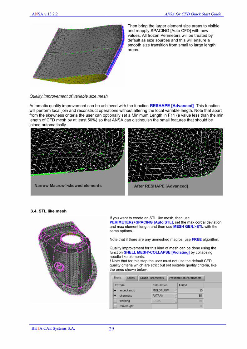
Automatic quality improvement can be achieved with the function RESHAPE [Advanced]. This function will perform local join and reconstruct operations without altering the local variable length. Note that apart from the skewness criteria the user can optionally set a Minimum Length in F11 (a value less than the min length of CFD mesh by at least 50%) so that ANSA can distinguish the small features that should be joined automatically.
3.4. STL like mesh
If you want to create an STL like mesh, then usePERIMETERs>SPACING [Auto STL], set the max cordal deviation and max element length and then use MESH GEN.>STL with the same options.
Note that if there are any unmeshed macros, use FREE algorithm.
Quality improvement for this kind of mesh can be done using the function SHELL MESH>COLLAPSE [Violating] by collapsing needle like elements.! Note that for this step the user must not use the default CFD quality criteria which are strict but set suitable quality criteria, like the ones shown below.
BETA CAE Systems S.A. 29
Narrow Macros->skewed elements After RESHAPE [Advanced]

ANSA v.13.2.2 ANSA for CFD Quick Start Guide
3.5. Summary of Automatic Quality Improvement functions
The table below summarizes the features of the main automatic quality improvement functions in the SHELL MESH group
Before Function After
FIX QUAL
fix quality violations by small nodal movements.Result can be undone using GRIDs>ORIGIN
RECONSTRUCT
Fix quality violations by remeshing. Results however are always bounded by existing Perimeters.
RESHAPE
Most advanced function as it performs local Perimeter JOIN operations and mesh reconstruction
All these functions can be used on meshed Macros or FE-mod mesh. For FE-mod mesh the identified feature lines behave like Perimeters. For example, RESHAPE can “join” the idenitfied feature lines (“perimeters”) if needed to improve the quality.
It is recommended to use the RESHAPE function because it is the most powerful one.RECONSTRUCT and FIXQUAL can be used for some final touch up actions, if needed.
BETA CAE Systems S.A. 30

ANSA v.13.2.2 ANSA for CFD Quick Start Guide
3.6. Useful Checks
Before proceeding to Layers or Volume meshing please check the following:
- CHECKs>PENETR. [Intersections] This will isolate all intersecting elements, which may exist due to bad cleanup, or badly meshed Macros.- CHECKs>PENETR. [Proximities] This will isolate all elements that have a proximity problem.Activate the option “Check positive orientation” to check only the gray side of the mesh for proximities. Proximity check takes place based on two parameters: the shell element length and a user specified factor, or an absolute distance. This check can be performed between different PIDs as well as within same PIDs. The option “Auto-Fix” is also available, so that ANSA can reconstruct and refine the mesh locally. Ensure that you use “Auto-Fix” on selected areas so that you can determine whether it should take place or not.- CHECK [Duplicate] This will isolate any duplicate elements that may exist, although rarely. Check if there is a topological problem there. - CHECK>MESH>[Sharp Edges] This will isolate elements that form very narrow or steep angles that may cause problems in layer generation or volume meshing.- ISOLATE>BOUNDS [Single and Triple] This will identify unwanted single or triple connectivity areas of the surface mesh. You can also see this in BOUNDS view mode: Deactivate visibility of PERIMETERs, HOTPOINTs, SHADOW, WIRE and activate BOUNDs and GRIDs (The GRIDs flag is useful for the visual detection of small bounds in a big model).
- GRID and ELEMENT IDs. Prior to volume meshing or output or merging of large models it is also recommended to renumber the IDs of Grids and Shell Elements, to ensure that all occupy the lowest possible values.
Go to DECKs>GRIDs>UTIL [Renumber All]. Type in start at 1 and press OK.
Perform the same for elements from DECKs>ELEMENTs>UTIL [Renumber] Select all the elements, press middle mouse button and start from ID=1.
You can also use the UDF function RenumberModel (see section11) to automatically perform the renumbering of the model.
BETA CAE Systems S.A. 31

ANSA v.13.2.2 ANSA for CFD Quick Start Guide
4. Layers
When you generate layers consider the following:- Which are the surfaces from which you grow layers- Which are the surfaces on which you want to adjust/connect the layers sides to. Is the angle of these side meshes suitable for auto-connection?- If you leave any layer sides not connecting to a surface, ensure that you set a properly small length there, so that the exposed quad faces of the layers have a good aspect ratio (less than 5 for example). This is very important, so that the pyramids that will grow from these facets are also of good quality. In addition the internal angles of the exposed quad facets should lie within 20 to 160 degrees. Alternatively use the option of generating non-conformal interfaces, which results in a much more robust meshing approach.- You should start with a relatively good quality surface mesh. However, thanks to the advanced ANSA capabilities of layer excluding, collapsing and squeezing, you can start with a moderate quality mesh and ANSA can automatically remove layers from bad surface mesh regions.
There are three options that ANSA can automatically overcome layer generation problems (due to intersections, proximities or element quality violation).
Squeeze Layers
Advantages:- Can be applied on penta or hexa layers- Does not alter the mesh type
Disadvantages:- Cannot overcome all problems. In case where the original mesh has areas where no normal vector can be calculated or no layer of acceptable quality generated, Layers Generation will stop and these areas will be placed in a SET for the user to examine.- Changes locally the specified layer height.
Collapse Layers
Advantages:- Can overcome any problem
Disadvantages:- Cannot be applied on hexa layers, only on pentas- Changes the mesh type around the collapsed areas and creates pyramids and tetras in the layers
Tips:When using collapse it is better to switch Squeeze option off, so that you do not end up with skewed tetras and pyramids due to the collapsed prisms
Exclude Layers
Advantages:- Can be applied on penta and hexa layers- Can overcome any problem- Does not change the mesh type
Disadvantages:- Leads to exposed side quad facets of the layers. In these cases it is recommended to use the option of non-conformal interfaces, as pyramid generation may have problems with very high aspect side quad facets.
BETA CAE Systems S.A. 32
ANSA v.13.2.2 ANSA for CFD Quick Start Guide
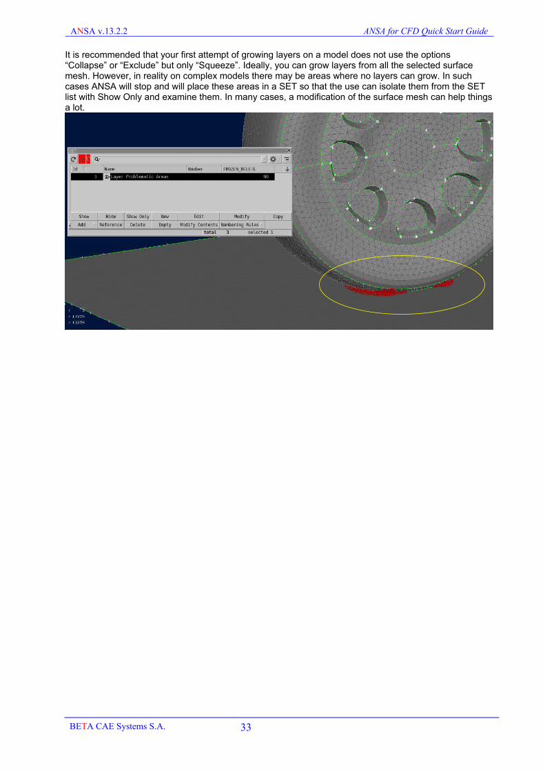
It is recommended that your first attempt of growing layers on a model does not use the options “Collapse” or “Exclude” but only “Squeeze”. Ideally, you can grow layers from all the selected surface mesh. However, in reality on complex models there may be areas where no layers can grow. In such cases ANSA will stop and will place these areas in a SET so that the use can isolate them from the SET list with Show Only and examine them. In many cases, a modification of the surface mesh can help things a lot.
BETA CAE Systems S.A. 33

ANSA v.13.2.2 ANSA for CFD Quick Start Guide
5. Surface Wrapping
Surface wrapping is a meshing technique that should be used when the input data are either too complex to extract the wetted surfaces from, create a water-tight geometry and clean it up, or when the input data is raw tessellated STL with several problems like intersections and gaps. The process of wrapping is described with the help of the following sketches.
Initial surface description full of openings, intersections and overlaps
Generation of background octree hexa mesh
Identification of intersecting hexas with original surface description and marking of these elements in blue
Extraction of the outer skin (green) of the identified intersecting hexas
Projection of the green skin on the original surfaces A water tight surface mesh (green) is created
In this way Wrapping overcomes all geometry problems. Still, wrapping should only be used if the conventional way of geometry cleanup and shell meshing (which always gives the best quality results) is very labor intensive.
BETA CAE Systems S.A. 34

ANSA v.13.2.2 ANSA for CFD Quick Start Guide
5.1. Variable size wrapping
Surface wrapping is a powerful tool that can be used in ANSA to create watertight models in a fraction of the time needed. Below is a summary, while more info can be found in the tutorials and the User Guide.
Select if you want Outer or Inner wrapping.If you select inner specify the number of the first N largest identified volumes to be wrapped
Specify the global min and max lengths (these can later be changed for each PID in the next window, if needed)
Feature lines above this angle will be identified and captured by the wrap tool.
Curvature refinement will be applied to ensure good mesh resolution
Pre-wrap treatment requires extra time, as it carries out additional checks and fixes, which may not always be necessary. This option should be skipped if the user performs some steps in advance, see section 5.1
Post-wrap treatment is highly recommended because it improves the mesh quality. Nevertheless, it may lead to some mesh problems which should be identified and fixed by the user, see section 5.2.
In the local control window the user can set different settings for each PID or Part. In addition they can set proximity refinement control.
The user can select which PIDs to wrap and what min and max length each one should have.
Property/Part proximity and Self-proximity can be activated for each property.
In order to ensure adequate refinement the user can specify a min length reduction factor value in the range 0.1<f<1.0. In this way, ANSA is allowed to locally drop the local min length of the property in order to ensure contact prevention. For example for a PID with min length 4 and a reduction factor of 0.2, the length may drop down to 0.8.
BETA CAE Systems S.A. 35
PID proximityrefinement
self proximityrefinement

ANSA v.13.2.2 ANSA for CFD Quick Start Guide
5.2. Preparation for wrapping
Depending on the input data the following actions should be taken prior to the wrap tool:
Input Data Pre-wrap actions
STL 1) STL data do not carry connectivity information, which is necessary for feature line recognition of the model in wrapping. Use SHELL MESH>FEMTOPO to establish nodal connectivity.2) Examine the model for openings. Use SHELL MESH>HOLE [Fill Hole] or FILL GAP>FREE [Edges] in order to manually close identified openings.
CAD surfaces
1) Ensure that most of the Faces are topologically connected. Small gaps and triple CONS are not however a problem for wrapping.2) If there are small openings that you do not want to keep, use FOCUS>ISOLATE [TUBES] isolate on the screen small inner passages like tubes and bolt holes on solid parts. Delete these Faces and then use CONS>FILL HOLE to close the created openings in the solid model.3) Inspect the model and create new Faces to close any openings that are larger than the wrap minimum length, or to cover any details that should not be captured by wrap.4) The Macros should be meshed! Meshing the model prior to wrapping ensures that you assign correct element length on the model, because the wrapping tool will create a wrap mesh with similar shell mesh variations as the original model. Hence meshing the model allows you to control the element length of the resulting wrap mesh. You should not worry about the quality of this mesh, just have it there as shell size information.The best way to mesh the model is to use PERIMETERs>SPACING [Auto CFD] (specifying a min/max length and sharp edge length) and then MESH GEN.>CFD. Check for any remaining large unmeshed Macros and use another algorithm like FREE. Check again if there are any large unmeshed Macros. The small ones you can ignore as the wrap mesh will cover them.Alternatively, if the model is very large, you can also use PERIMETERs>SPACING [Auto STL] and MESH GEN>STL. This will be faster than CFD meshing process.
5.3. Post-wrap checks
Performing a good quality wrap that captures all the important details of the model may take a few iterations until you achieve the best result.
Once you are satisfied with the final wrap it is recommended that you delete the original mesh/geometry.In the Part Manager, ANSA places the wrap mesh in a separate Part. You can delete the original model with right-click and delete. This will leave a “lighter” database and you will be able to focus more easily on the final checks of the wrap mesh.
After wrap with post-wrap treatment the user must check for intersection, proximities, flipped elements and quality issues. The checks below should take place one after the other and possibly in more than one loops.
CHECK>Penetrations [Intersections] Find problems and fix them with GRIDs>PASTE and ELEMENTs>DELETE and SHELL MESH>HOLE [FILL HOLE]
CHECK>MESH>Sharp Edges Find problematic flipped elements and fix them like Intersections
CHECK>Penetrations [Proximities] Find proximity problems and fix them with GRIDs>MOVE
Mesh quality check Use RESHAPE [ADVANCED] to fix remaining quality violations
CHECK>Duplicate Remove any duplicate elements
ISOLATE>BOUNDS [Single or Triple] Check if there are unwanted free edges or triple connectivity
All the above checks should be performed iteratively until all problems are eliminated.
Finally, if you want to coarsen the mesh, you can set a Min Length value in F11 and then use RESHAPE [Advanced] again. This will remove smaller elements from the model and reduce the element length.
BETA CAE Systems S.A. 36

ANSA v.13.2.2 ANSA for CFD Quick Start Guide
In addition you can also use theCHECKs>Checks Manager.This tool contains set of predefined multiple checks.One of them is a check for CFD_post_wrapthat includes all the above mentioned checks.
Use “Execute on Visible” to apply all these checkssimultaneously.
6. Identifying leaks
There are three ways to identify a leak in ANSA, depending on the type of shell mesh investigated. “Dirty” or good quality mesh. “Dirty” mesh implies mesh with gaps, overlaps, intersections etc, like an imported STL mesh with many problems. For such cases the two ELEMENTs>WRAP algorithms can be used.Clean mesh, on the other side, implies a good quality shell mesh without intersections or highly distorted elements. Such a case could be a complex CFD shell mesh model just prior to volume definition, but due to its complexity an opening may be left and must be found prior to correct volume definition. In such a case the function ISOLATE>Short Path [Leak] should be used.
6.1. Leak check on dirty meshes for wrapping
Use the ELEMENTs>WRAP [Variable Length] function with the option Leak Check. Specify a point insidethe dead region. If there is a leak, ANSA stops and displays the path through it by creating a 3D Curve. Use TOPO>CONS>INFO, select the Curve to become highlighted for clearer identification of the leak.Note: The point must NOT lie on the surface mesh, but inside the dead volume.If such coordinates are not known, then place the mouse in the xyz fields and press F1 to pick from the screen. Pick some nodes to get their CoG and then confirm.
Another way of identifying a leak is using the ELEMENTs>WRAP [Constant Length] tool.Set a uniform length equal to the min size of the leak to be detected and run the function.
We start from an STL meshed geometry, where most checks (BOUNDS, FEMTOPO, FILL HOLE) have been performed.
BETA CAE Systems S.A. 37

ANSA v.13.2.2 ANSA for CFD Quick Start Guide
As these wrap runs will be for leak detection only use the WRAP [Constant Length->Smooth wrap] option which runs fast as it does not capture the surface details. Note that you should specify as length the minimum length that you will use in the Variable Length wrap to ensure that the smallest possible leak will be detected.
Then remove the visibility of the original model (Macros OFF) and make a NOT selection to see inside the smooth wrap.
The wrap has leaked inside as gray color elements appear inside.In order to detect the location of the leak you should use the function FOCUS>ISOLATE>SHORT PATH [ON SHELLS].Activate the function ISOLATE>SHORT PATH [ON SHELLS]. Select with left mouse button one element from the inner side and confirm with middle mouse button. The selected element appears highlighted in blue. Next select an element on the other side. Then press FOCUS>ALL
Finally confirm with middle mouse button.
ANSA isolates and highlights the shortest path between these two elements. This short path goes through the hole of the model.
Bring back the visibility of the model (MACROS ON) to compare the path with the model and find the leak.
Go to TOPO menu and close the opening by creating new Faces. Make sure you mesh these Faces in MESH menu before you wrap again!.
If this was the only opening in the model then this fix should do the trick and the user can delete the draft wrap (from the Part Manager with right-click Delete) and then wrap from the start.
However this may not be the case. In order to use the same wrap for the detection of another potential opening the user must bring the neighboring elements around the leak using FOCUS>AND a couple of times and then delete that area of the wrap mesh. This will disconnect the inner and outer wrap surfaces (at least at that location).Then press ALL and check again with ISOLATE>SHORT PATH [On SHELLS] to find the next opening (if there is one).
BETA CAE Systems S.A. 38

ANSA v.13.2.2 ANSA for CFD Quick Start Guide
6.2. Leak check on good quality shell mesh
The function ISOLATE>SHORT PATH [LEAKs] can only be used on good quality mesh (not STL mesh with intersections and other problems) if there is a suspicion that there is a leak which is not easy to locate in a complex model, and the automatic Volume detection algorithm fails.
The user specifies one outer point (green) and one (or more) inner ones (red).Points must NOT lie on the surface mesh but inside or outside the volumes in question.To select easily a point that lies inside the volume and noton the surface, select more than one points and ANSAdisplays the CoG of them and highlights it.Then proceed with the next source point, select manynodes on the surface, ANSA displays the CoG. Confirm.
Finally confirm all selections with middle mouse andANSA will calculate a curve of the Leak Path, if such a path exists.The leak can be found by tracing this path.
BETA CAE Systems S.A. 39

ANSA v.13.2.2 ANSA for CFD Quick Start Guide
7. Volume Meshing
Having created the layers and their shell cap, you should now proceed with the definition of the Volume entities. This can be easily done with the function VOLUMEs>DEFINE [AUTO DETECT].All the Volumes defined manually or detected by ANSA are listed in the VOLUMEs>LIST window.
You should check this list to monitor the type, Name, PID and status of the Volumes.
Note that Large volumes (by default larger than 5 million elements) are drawn in “Outline Draw” mode. This means that only the outline of the volume is visible and no Focus commands can be applied, in order to accelerate the view manipulation of large models. Of course all remaining ANSA functionality, like quality improvement functions and output can be performed normally on such volumes.
7.1. Manual Volume Definition
First, isolate the Macros that define the Volume, using FOCUS commands either in PID or ENT mode and use VOLUMEs>DEFINE [MANUAL] and select all visible Macros with box selection.
Place the Volume entity in a new separate Part (to facilitate later its handling) and then assign a PID to it.Here it is recommended to assign it to the same PID as that of the layers underneath it,In fact, if there is no specific need later for post-processing of volume zones, it is better to assign the same PID for all fluid elements.You can always manage the Volumes in your model using the VOLUMEs>LIST list window, edit any volume and change its PID as well.
7.2. DETECT functionality for Volume Definition
Defining Volume entities from complicated assemblies can be a complicated task. Sometimes the separation of PIDs from the list is not enough to isolate all the Macros that should form a closed Volume. For complicated models you can use the VOLUMES>DEFINE [AUTO-DETECT] function. This function can detect and define automatically volumes from meshed Macros or FE-model mesh. Remember to have the Highlight button activated in the Volume list. All Detected Volumes are placed in separate Parts in the Part Manager.
BETA CAE Systems S.A. 40

ANSA v.13.2.2 ANSA for CFD Quick Start Guide
7.3. Meshing the Volume
ANSA provides different meshing algorithms for volume meshing, as shown in the table below:
Tetra Rapid Very fast and robust tetra mesh generation for any model. Recommended for all cases.
Tetra CFD Very robust tetra mesh generation for CFD models with large variation in element length on the surface. Significantly slower than Tetra Rapid, it should only be used if Tetra Rapid fails to mesh a specific volume..
Tetra FEM Very robust tetra mesh generation smaller models with thin volumes. Significantly slower than Tetra Rapid, should only be used if Tetra Rapid does not perform well in a specific case.
Hexa Interior Fully conformal variable hexa mesh inside the domain with prism and pyramids transitions between different hexa sizes and with pyramids and tetras near the surface.
HEXAPOLY A combination of variable size Hexa and Polyhedral elements inside the domain with transition with polyhedrals and tetras near the surface.
CONV2POLY A pure polyhedral mesh can be generated from the conversion of any tetra or hybrid mesh.
These algorithms are controlled by the Options window at the bottom right of the ANSA interface.Specify the maximum length for the tetras and the growth rate, and select a quality criterion type and target threshold value (for example Fluent skewness =0.85).
You can also create Size Boxes that will control the maximum tetra size at certain locations of the model. These Boxes are created from any CFD Deck from the Size Box group of functions.
BETA CAE Systems S.A. 41
ANSA v.13.2.2 ANSA for CFD Quick Start Guide
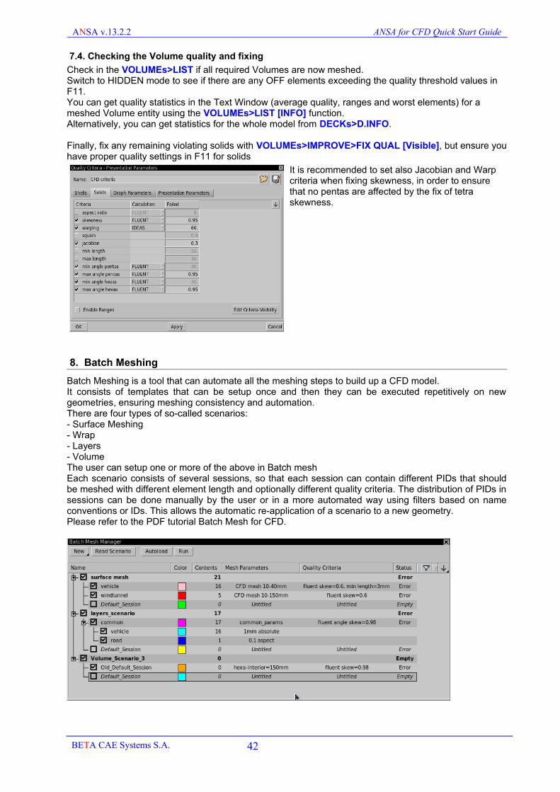
7.4. Checking the Volume quality and fixing
Check in the VOLUMEs>LIST if all required Volumes are now meshed.Switch to HIDDEN mode to see if there are any OFF elements exceeding the quality threshold values in F11.You can get quality statistics in the Text Window (average quality, ranges and worst elements) for a meshed Volume entity using the VOLUMEs>LIST [INFO] function.Alternatively, you can get statistics for the whole model from DECKs>D.INFO.
Finally, fix any remaining violating solids with VOLUMEs>IMPROVE>FIX QUAL [Visible], but ensure you have proper quality settings in F11 for solids
It is recommended to set also Jacobian and Warp criteria when fixing skewness, in order to ensure that no pentas are affected by the fix of tetra skewness.
8. Batch Meshing
Batch Meshing is a tool that can automate all the meshing steps to build up a CFD model.It consists of templates that can be setup once and then they can be executed repetitively on new geometries, ensuring meshing consistency and automation.There are four types of so-called scenarios:- Surface Meshing- Wrap- Layers- Volume The user can setup one or more of the above in Batch meshEach scenario consists of several sessions, so that each session can contain different PIDs that should be meshed with different element length and optionally different quality criteria. The distribution of PIDs in sessions can be done manually by the user or in a more automated way using filters based on name conventions or IDs. This allows the automatic re-application of a scenario to a new geometry.Please refer to the PDF tutorial Batch Mesh for CFD.
BETA CAE Systems S.A. 42

ANSA v.13.2.2 ANSA for CFD Quick Start Guide
9. CFD interfaces
Apart from the mesh generation, the user can also setup the names of the surface and volume properties from the Property list to setup properly the CFD model. You should always specify at the start for which solver you want to prepare a mesh. This is done from DECKs pull down menu (by default OpenFOAM). This will allow ANSA to provide also the respective boundary condition types in the Property List.As CFD volume models tend to be large, it is recommended to setup all the surface boundary condition names and types before volume meshing, while the file is still small. After volume meshing you can assign the correct fluid properties also before file output.
An example of a model with boundary condition types for Fluent is shown below:
The BC types can also be represented visually on the model if the user switches to VISIB>ENT to VISIB>BC. BCs are represented in Fluent convention coloring (blue inlet, red outlet etc).
The Property list contains all zones and respective BC types. The user can double click on a property to Edit its BC type in the card.
The property list supports also mass modification of several properties.Select the properties, right click on the column that you want to change and select the type.
BETA CAE Systems S.A. 43

ANSA v.13.2.2 ANSA for CFD Quick Start Guide
ANSA can generate CFD models for several solvers. Depending on the solver, there are various levels of support, from plain mesh I/O to full case and solver setup.The following table concentrates all the supported solvers:
OpenFOAM A full case can be setup in ANSA, including the mesh, property names, boundary and initial conditions and the solver settings (controlDict etc). Property names and boundary conditions can be setup from the Property list, while the rest is controlled from DECK>AUXILIARIES>SOLVER INFOYou should output a full surface AND volume mesh for OpenFOAM
Fluent(*.msh))
A surface or volume mesh and their zone names and boundary condition types can be setup. Zone names and BC types are setup in the Property list.
Fluent 2D(*.msh)
Generate the model in the x-y plane and assign from the Property list the fluid zone names. From DECK>FLUENT 2D>BCs>BC [New] and [List] you can assign the edge boundary condition name and type on selected CONS or FE-mod edges.Only output of Fluent 2D *.msh files is supported.
StarCCM+(*.ccm)
Specify in DECK>STAR>AUXILIARIES>SOLVER INFO if you want to create a mesh for StarCCM+. The respective BC types will be available in the Property list. You should output a full surface AND volume mesh for StarCCM+
StarCD(*.inp)
Specify in DECK>STAR>AUXILIARIES>SOLVER INFO if you want to create a mesh for StarCD. The respective BC types will be available in the Property list.
CFD++ Mesh and property names are supported.
CFX(*.cfx5)
Mesh and property names can be output in CFX5 format to be read into CFX through mesh>import. You should output a full surface AND volume mesh in cfx5 format
SC/TETRA(*.pre)
Mesh and property names are supported. You should output a full surface AND volume mesh for SC/TETRA
UH-3D(*.uh3d)
Mesh, property names and boundary condition types are supported
POWEFLOW(*.nas)
Surface mesh and property names can be read into PowerFLOW through the NASTRAN output format
CGNS(*.cgns)
For other CFD codes (like Code Saturn) the CGNS format can be used for mesh I/O. Input accepts structured and unstructured formats, but output only unstructured)
BETA CAE Systems S.A. 44

ANSA v.13.2.2 ANSA for CFD Quick Start Guide
10. Model generation Checklist
At every stage of the model preparation there are certain checks that should take place before proceeding to the next one. The table below lists a summary of the steps that should take place in the “traditional” CFD mesh preparation process. These are geometry clean up, watertight model creation, surface meshing, layers and volume mesh generation. For surface wrapping please refer to section 5.
Geometry preparation
Faces Resolution Different models require different discretization length. Assign a suitable element length on your model from MESH>PERIMETERs>LENGTH or SPACING [Auto CFD]. This will allow you to better display the model details.
Faces Orientation Activate VISIB>SHADOW mode. All Faces should be uniformly oriented. Gray is the positive side and yellow the negative. Use FACEs>ORIENT to assign uniform or invert the orientation.
Unnecessary Hot Points Perform a HOT>POINTS>DELETE with box selection to remove any unnecessary Hot Points.
CHECK>GEOMETRY The user can use the CHECK>GEOMETRY function to identify several common problems and then use the right-click Fix option in the list of identified errors. Triple CONS may exist in a CFD model on purpose. Single CONS should only exist if the model has zero-thickness walls (baffles).
CHECK>PENETRATION>INTERSECTIONS
The model should also be checked for penetrations. If any are identified the user should use the function FACEs>INTERSECT to fix any intersecting geometry
ISOLATE>FLANGES>PROXIMITY
This check will identify parts that are very close together (although not actually intersecting). The absolute distance value is left to the user to decide. Very often such geometries also need to be topologically connected, using TOPO functions like CONS>PROJECT and FACEs>TOPO.
CHECK>GEOMETRY As above.Do not proceed to MESH unless the CHECK>GEOMETRY is clear (green).
Surface meshing
PERIMETERs>LENGTHorPERIMETERs>SPACING [Auto CFD]
Ensure that you assign to all Perimeters the desired Element Length. For uniform element length mesh, use PERIMETERs>LENGTH, while for variable, curvature dependent surface mesh use PERIMETERs>SPACING [Auto CFD]
FOCUS>UNMESHED After using the various meshing algorithms (ADV.FR, CFD etc) the user should check for UNMESHED Macros. Use alternative algorithms, or cut them into smaller macros, or check the underlying geometry.
VISIB>HIDDEN
FOCUS>EXTREME
Switching to HIDDEN mode allows you to check if there are violating elements, reported in the legend as OFF.Use SHELL MESH>RESHAPE [Advanced] and SHELL MESH>FIX QUAL [Visible] to fix them automatically. If there are any remaining OFF elements, then use FOCUS>EXTREME ALL or WORST to identify and examine these areas. You may have to change the geometry or the element length to better resolve such areas. Do not proceed to layers or volume meshing if you still have OFF elements on the surface.
BETA CAE Systems S.A. 45

ANSA v.13.2.2 ANSA for CFD Quick Start Guide
CHECK>PENETRATION>INTERSECTIONS
Check for any intersections, this time at the mesh level. Fix them all.
Surface mesh orientation If layers are to be generated ensure that the orientation is uniform and correct for the whole of the model. Use MACROs>ORIENT.
CHECK>PENETRATION>PROXIMITIES
Check for proximities that may lead to problems in layers of volume meshing.The check distance can be an absolute value, but it is better to specify an element length factor (<1). This implies that the check distance will be equal to the factor multiplied by the local element length.
Activate also the options to check proximities among areas with the same PID also and provided that you have oriented your shell mesh (MACROs>ORIENT) correctly, check only the positive side (gray one) for proximities.
CHECK>MESH>SHARP EDGES
This check will identify very sharp angles in the surface mesh. These may be due to flipped elements on the surface or to the actual nature of the geometry. Such areas may cause problems, especially for layers generation, so you should treat them appropriately.
VISIB>BOUNDS
CHECK>MESH>SINGLE/TRIPLE BOUNDS
Activate VISIB>BOUNDs and de-activate VISIB>HOT POINTs and PERIMs to see if there are any single or triple boundaries unintentionally. Alternatively use the CHECK>MESH>BOUNDs. Ensure that the identified boundaries are correct.
CHECK>DUPLICATE Ensure that there are no duplicate elements on your model.
Layers generation
VOLUMEs>LAYERS Ensure you have assigned correct PIDs to the model, as the layers will be generated based on this grouping of the model. Ensure also that the surface mesh orientation is correct. Try to grow layers only with the squeeze option. If ANSA stops and detects problematic areas, open the SET window and make visible (Show Only) these areas.Investigate the cause of layer failure from these areas: poor mesh quality, very tight angles, proximities? If possible make corrections to the surface mesh. Otherwise, deactivate the “Squeeze” option and activate the “Collapse” or “Exclude” ones.
Volume meshing
VOLUMEs>LIST Having defined the volumes from VOLUMEs>DEFINE, use the available volume meshing algorithms. Open the VOLUMEs>LIST and check that all volumes are marked as Meshed. Check also that they have correct Property Name. Select a Volume and press Info to get quality information.
VISIB>HIDDEN Switching to HIDDEN mode allows you to check if there are violating elements, reported in the legend as OFF. You can optionally press FOCUS>EXTREME to isolate them.To fix them, press FOCUS>ALL, ensure that the visibility of Macros, FE-mod and VOLUMEs are all active and then use VOLUMEs>IMPROVE>FIX QUAL [Visible]. You may have to press the function again in order to fix any remaining elements.
Output
Before outputting the model it is recommended that you clear the database from any empty or unused grids, PIDs, etc, using the function FILE>COMPRESS. Consider also renumbering all grids and elements if you are dealing with a very large model. You can also use the UDF function RenumberModel (see section 12). Bring ALL entities you want to output to visible. Ensure MACROs and VOLUMEs are active (and FE-mod of course if you have FE-model mesh in your model as well). Then use the Output Visible option.
BETA CAE Systems S.A. 46
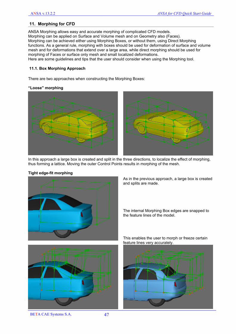
ANSA v.13.2.2 ANSA for CFD Quick Start Guide
11. Morphing for CFD
ANSA Morphing allows easy and accurate morphing of complicated CFD models.Morphing can be applied on Surface and Volume mesh and on Geometry also (Faces).Morphing can be achieved either using Morphing Boxes, or without them, using Direct Morphing functions. As a general rule, morphing with boxes should be used for deformation of surface and volume mesh and for deformations that extend over a large area, while direct morphing should be used for morphing of Faces or surface only mesh and small localized deformations.Here are some guidelines and tips that the user should consider when using the Morphing tool.
11.1. Box Morphing Approach
There are two approaches when constructing the Morphing Boxes:
“Loose” morphing
In this approach a large box is created and split in the three directions, to localize the effect of morphing, thus forming a lattice. Moving the outer Control Points results in morphing of the mesh.
Tight edge-fit morphing
As in the previous approach, a large box is created and splits are made.
The internal Morphing Box edges are snapped to the feature lines of the model.
This enables the user to morph or freeze certain feature lines very accurately.
BETA CAE Systems S.A. 47

ANSA v.13.2.2 ANSA for CFD Quick Start Guide
11.2. BOX preparation
When creating a large BOX using the BOXES>ORTHO function, all selected elements are loaded in the BOX.
Using BOXES>INFO the user can visualize the contents of a Morphing Box.
When splitting this Box, ANSA automatically redistributes the elements to the proper Boxes, as shown below.
In every change of the topology or shape of the Boxes during their preparation for the morphing, ANSA checks the contained entities and the boundaries of the Boxes. Because real CFD models usually contain very large number of elements, these checks delay the Box manipulations. It is therefore recommended to start your work with an “empty” Box. With an “empty” box the user can perform operations like split, and control point movement much faster than with a loaded Box. To empty the contents of the original Box, simply de-activate temporarily the visibility of the FE-mod flag and perform a BOXES>LOAD [Visible] operation.In the end when you have split, reshaped, edge-fit your boxes, just before doing the Morphing, you can perform a BOXES>LOAD [Visible] or [Whole DB] operation to load the proper elements to the proper Boxes.
Remember that every time you make a modification of shape of the Boxes (without morphing) you should use the BOXEs>LOAD function to ensure that the proper elements are loaded to the proper Boxes.
Failure to do so may result to such discontinuities during morphing, like the one shown here.
BETA CAE Systems S.A. 48

ANSA v.13.2.2 ANSA for CFD Quick Start Guide
When creating boxes around a vehicle try to use as few splits as possible.
This makes the model easier to handle and also results in a smoother morphing.
Take also advantage of the GEOMETRY>TRANSF>LINK [Symmetry] to create LINK boxes as shown. A change on one side is mirrored on the other.
Observe how the splits “follow” the shape of the car....
…. in every direction.
BETA CAE Systems S.A. 49

ANSA v.13.2.2 ANSA for CFD Quick Start Guide
11.3. Box shape issues
When splitting the Boxes in order to edge fit the internal edges onto the feature lines of the model, you should take care that the morphing Boxes are as orthogonal as possible, and certainly do not have internal angles that exceed 180o degrees.
On the left image the Box that is inside the vehicle has an angle higher than 180, while in the second image a better Box construction results in better angles.
In the example below again the left model has two boxes with very wide angles.The Box topology on the right has much better shaped Boxes.
Creating the Boxes is similar to creating Boxes for Hexa mesh. Like in hexa mesh, the better these blocks are, the better the result. You can also check for invalid boxes with MORPH>CHECKS>DISTORTED.
11.4. Box boundaries
The Boundaries of the Boxes should be placed sufficiently away from the model to be morphed.
On the left the first model has some boxes that are small.
The model on the right has much better boxes.
BETA CAE Systems S.A. 50
Non-optimum topology improved topology
confined morphing space adequate morphing space
bad internal angle good internal angle

ANSA v.13.2.2 ANSA for CFD Quick Start Guide
11.5. Larger Boxes maintain orthogonality
The images below indicate that even if the initial Boxes have good internal angles, these angles may be violated if morphing takes place. Having larger boxes reduces this risk.
11.6. Large Boxes result in smaller deformations of the volume mesh
BETA CAE Systems S.A. 51
confined morphing space Bad resulting box angle >180o
adequate morphing space OK resulting box angle
confined morphing space
adequate morphing space
squeezed solids
good solids

ANSA v.13.2.2 ANSA for CFD Quick Start Guide
11.7. Tangency condition
Depending on the status of the CHECKS>TANG flag, when you split Boxes ANSA assigns or not tangency conditions between adjacent Boxes. Tangency is indicated by the thicker lines and can be added or removed using the EDGEs>TANGENCY [MANUAL and Remove] functions. In most cases it is better not to have tangency applied because it may over constrain the form of the Boxes. It is therefore recommended that you remove all tangencies and then add them selectively at areas and along specific directions that you really want them.
The following simple example demonstrates the effect of tangency.
You could start without any tangency over all edges and then selectively add them manually, where it is really needed.
BETA CAE Systems S.A. 52
over constrain no constrain
with tangency without tangency
without tangency tangency only along one direction

ANSA v.13.2.2 ANSA for CFD Quick Start Guide
11.8. Additional User Tangency condition
Sometimes it is very useful to impose and freeze tangency in a certain direction.This can be achieved through EDGES>TANGENCY [USER]Select NEW pick an edge and confirm.When the window opens pick two point positions in order to define the required direction. By default ANSA creates the User Tangency in the current direction of the edge.
A user imposed tangency is displayed with a yellow arrow.
In this example, the tail of the vehicle is squeezed in width and the rear roof is lowered.These changes do not however affect the tangency of the model “upstream” and maintain a smooth shape variation.
The image on the left shows how a USER TANGENCY condition can improve the morphing results.
Without any Tangency, sharp discontinuities arise.
With standard Tangency there is no discontinuity in curvature BUT a movement of the rear end of the vehicle affects upstream the model as shown on the left.
With USER Tangency, on the right, the continuity is guaranteed and also there is no distortion upstream, because the edge is “frozen”.
BETA CAE Systems S.A. 53

ANSA v.13.2.2 ANSA for CFD Quick Start Guide
11.9. Tolerances
Tolerances is an important issue, especially when morphing CFD models that contain very small elements (especially in volume boundary layer elements).
To avoid accuracy errors you should activate the extra-fine tolerances inSETTINGS>MORPH SETTINGS
(in general the tolerances should be two orders of magnitude smaller than the smallest element length).
11.10. Edge fitting on features of the model
When using the MODIFICATION>FIT [EDGES] function to snap the Morphing Box edges on the feature lines of the model it is not recommended to place an excessive number of Control Points.Too many Control Points delay all the algorithms without actually improving the accuracy of the result.
BETA CAE Systems S.A. 54
mesh wrinkles smooth mesh
excessive number of Control Points normal number of Control Points
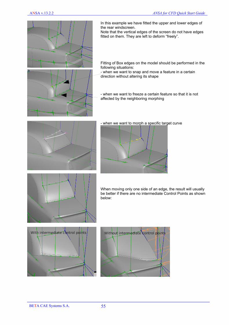
ANSA v.13.2.2 ANSA for CFD Quick Start Guide
In this example we have fitted the upper and lower edges of the rear windscreen.Note that the vertical edges of the screen do not have edges fitted on them. They are left to deform “freely”.
Fitting of Box edges on the model should be performed in the following situations:- when we want to snap and move a feature in a certain direction without altering its shape
- when we want to freeze a certain feature so that it is not affected by the neighboring morphing
- when we want to morph a specific target curve
When moving only one side of an edge, the result will usually be better if there are no intermediate Control Points as shown below:
BETA CAE Systems S.A. 55
With intermediate control points Without intermediate control points

ANSA v.13.2.2 ANSA for CFD Quick Start Guide
11.11. Troubleshooting morphing boxes
Morph boxes should be as orthogonal as possible. Avoid severely distorted boxes because they will give bad morphing results. You can use the CHECKs>DISTORTED to find badly shaped Morph Boxes and fix them.
The message “overlapping morphing boxes” may appear when trying to morph a model. In this case morphing will not be allowed because there is conflict with respect to the contents of the boxes.
ANSA reports the Ids of conflicting boxes in the Text areafor example Overlapping morphing boxes selected (morph id: 201 and 222).
In such cases use the DatabaseBrowser to locate these boxes
Double click in the MORPHBOX entry to open the list of Morphing Boxes.
In the filtering section at the top, type the requested Ids and clickon Show Only
Overlapping boxes usually occur because some elements are loaded to more than one boxes, usually when one has morphing boxes inside other morphing boxes, and they move the control points of both boxes simultaneously. In such cases ANSA cannot understand how to move these elements (which box should affect them?) and prints this message.
Overlapping boxes may also occur if the box construction is not proper. This happens when the shape of the boxes is severely distorted or if there are duplicate Control Points (that is points within a very small distance). Use CONTROL POINTS>RMDBL in such cases and specify a tolerance, say 5mm and select and delete the identified duplicate control points. Use also CHECKS>DISTORTED to identify bad boxes.Then use BOXES>LOAD again to load the proper elements to the proper boxes and proceed with morphing.
BETA CAE Systems S.A. 56

ANSA v.13.2.2 ANSA for CFD Quick Start Guide
11.12. Direct Morphing (without morphing boxes)
Morphing on Geometry (Faces) or surface mesh can be achieved very efficiently without the need of morphing boxes using the functionDIRECT MORPHING>DFM (Direct Fit Morph)
The user need to specify 3 groups of entities:
O What Moves as a rigid body
O What deforms to absorb the morphing
O What boundaries stay frozen
Move Types can be:
- Translation- Rotation- Scaling- Edge Fitting
Note that several combined movements can be performed in one step if required, for example a translation of one part of the model and an edge fit of another feature of the model to a target curve.
In this example the user selects the rear end of the vehicle to be moved in x direction.
The magenda colored Faces will be deformed.
The blue CONS will remain frozen.
ANSA performs the morphing automatically.
BETA CAE Systems S.A. 57

ANSA v.13.2.2 ANSA for CFD Quick Start Guide
11.13. Define MORPH Parameters
Once you have finalized the Morphing Box construction it is well worth defining the morphing Parameters from CONTROLS>PARAM [NEW]
Mainly used parameters areTRANSL, LENGTH (for slide action) and EDGE.FIT.
Having defined the parameters you will not have to select again the control points to perform the morphing, and these parameters are saved in the database.
11.14. The Deformation Morph Parameter
A different kind of Morphing parameter that is very useful is the DEFORMATION type.
Create one before you begin your morph operations, so that at any time during the morphing you can retrieve the original state (0) from from the current state (1), or interpolate between 0 and 1 or even extrapolate beyond this range.
The Deformation type parameter allows also the user to re-apply the same morphing on another model. To achieve this the user must define the deformation parameter prior to morphing.
Then, after all the morphing operations are complete and the final state is reached, the user can EDIT the parameter and set the Record status to OFF. This means that the target state (as well as the original) is now also locked.
All intermediate states can be retrieved by Morphing the parameter from 0 (origin) to 1 (final state)
The Boxes with the deformation parameter can be saved separately in an another ANSA database (see next section).
The Boxes saved as a separate ANSA database on their own can be morphed to their original state by MORPHING the value to 0, then loading or merging another mesh in them, loading the elements to the Boxes and and then morphing the parameter back to 1 again.
BETA CAE Systems S.A. 58

ANSA v.13.2.2 ANSA for CFD Quick Start Guide
11.15. Morph the geometry through deformation mapping
ANSA morphing using boxes is best practiced on the shell and volume mesh. However one also needs to be able to morph the actual Faces also. The best way to do this is to first perform the morphing on the mesh and then apply the same morphing in the end on the geometry. This can be achieved with the use of the Deformation morph parameter and the function DEFORM MAP.
Start with your original meshed model.Ensure that you have the VIEW MODE>MESH VIEW active. You should see the Geometry as meshed Macros and not as Faces.
Create the Boxes and LOAD>Visible the FE-Entities (that means the elements) and not the Faces.
Then create a new Deformation parameter.
In the card of the Deformation parameter ensure that you switch to Affected ->ALLThis means that the parameter will store the position of all the nodes of the model and not just the moved ones.This is needed to increase the accuracy of results in the deformation mapping later.
Perform all the morphing actions on the mesh of the Macros.You will notice that the Perimeters of the Macros remain at their original position, as the underlying geometry is not morphed.
Once you have finalized all the possible morphing actions on the mesh (which can be a sequence of several combined movements) you can check the deformation parameter and it will should you the total displacement from the origin.
BETA CAE Systems S.A. 59

ANSA v.13.2.2 ANSA for CFD Quick Start Guide
De-activate the VIEW MODE>MESH VIEW and then you will notice that the Faces are still at their original position.
The task now is to apply the deformation of the mesh on the geometry Faces.
Activate the function CONTROLs>DEFORM.MAP
This function maps deformation data on new geometries (Faces or FE-mod). The deformation data can some from an existing deformation parameter, or from a text file containing columns of x, y, z, dx, dy, dz.
Select the option “Deformation parameter” and press OK. In the parameter list window that opens next, select the deformation parameter that has recorded the mesh deformation. Press OK.
The selection window opens.The Deformation parameter keeps the deformation vector off for all the morphed nodes of the model. This number may be very large for a real model.
For this reason ANSA will perform Sampling from all the node data. By default it will use a maximum of 15000 points. You can increase this to 30 or 50 thousand but you should bear in mind that the computational effort for memory and time will increase geometrically.You can constrain the population of nodes on which sampling will be performed if you activate the “Sample data from visible” option. For example if you have also morphed a volume mesh in the same deformation parameter, you should make it not visible and use this option, in order to sample only from the surface mesh.
Finally select in Geometry mode which Faces should be morphed based on the deformation parameter.
Select the Faces you want to be morphed and confirm.
ANSA applies the same morphing on the Faces.
These can now be output in IGES, STEP orVDA-FS format.
BETA CAE Systems S.A. 60

ANSA v.13.2.2 ANSA for CFD Quick Start Guide
11.16. Part Manager structure
As a real life model morphing case can get complicated, it is highly advisable to use the Part Manager in order to manage the model. You should have in separate Parts or Groups the main mesh model, the Morphing Boxes, the original 3D curves of the feature lines of the model and the target 3D Curves, if any.
The feature lines of your model in the form of 3D Curves can be extracted by you using CONS2CURV from the original geometry (if it is available) or using the PERIMETERs>FL2CURV function.Target Curves can be either obtained from CAD department or even created within ANSA using several CAD functions in TOPO.As Curves do not have a PID it is recommended to place them in separate Parts.
!! Placing the Boxes in one Part allows the user to save them from the Part Manager (right-click SAVE) into a separate ANSA database. If there are any Morph Parameters, they will also be saved with the Boxes. This means that the user can use the same Boxes, input a new model in them, LOAD the boxes and perform morphing on the new model using the existing Boxes. In such a case the user may only have to make some adjustments or edge fit of the existing boxes to the new model. The Box topology or template can be the same.
BETA CAE Systems S.A. 61

ANSA v.13.2.2 ANSA for CFD Quick Start Guide
12. User Defined Functions for CFD models
ANSA Scripting language allows the creation of user defined functions. Below follow some sample user defined functions that may come to use in the manipulation of a CFD model.
TOOLS:
RenumberModel: This function renumbers the IDs of the Nodes, Elements and Properties so that they all start from 1. There is also the option to renumber the elements sequentially for each increasing PID.
ReadPIDList: This function can read a list of Properties from a comma separated file (*.csv) with two columns: Property IDs and Property Names.
Detect: This function makes the SET “Do not include in Detect” not visible and then proceeds with the actual Volume Detection. Useful when detecting volumes after boundary layer generation with exluded areas where duplicate elements are created by ANSA and placed in this SET.
OrientVolume: This function assigns uniform orientation to the volume of a user specified ID or to all visible Volumes, so that all its Macros or elements point inwards (gray orientation towards inside). Useful for orientation of surfaces prior to boundary layer generation.
ChangeBafflesProperty: This function should be used after ISOLATE [Baffles]. It will change the property of the identidied baffles to a new property name with the added keyword *_zero_baffle. This function is useful to separate the PIDs of baffles in order to create layers from both sides of zero thickness walls afterwards.
ConnectSTLPerProperty: This function applies FEMTOPO on each PID of an assembly, separately.
SeparateUnonnectedPIDs: Detects unconnected PID regions and places them in separate PIDs.
MorphAccordingDeformations: Function that applies morphing on Faces based on predefined text file list of deformations (dx, dy, dz, x, y, z) as calculated from an FEM analysis or from an existing ANSA morph deformation parameter.
UndoReshape: This function undoes all the actions of the function SHELL MESH>RESHAPE, if the result is not satisfactory, by releasing all joined perimeters, initializing lengths and bringing all nodes to their origin. The mesh is be erased!
INPUT OUTPUT:
OutputOpenFoamPoints: This function can be used in order to output only the points file of the polymesh section of an OpenFOAM case. The idea is that after morphing you do not have to write the whole mesh but just the new point coordinate.
InputAssembly: This function takes as input a folder path and will read recursively all sub folders and input all the contained STL or NASTRAN or IGES or STEP files. Each folder will become a Group and each file a Part. In this way the whole assembly structure will be reproduced in the ANSA Part Manager
PIDToFile: This function outputs each PID of a model in separate ANSA, STL or NASTRAN files.
PartToFile: This function outputs each Part or Group at the top level of the Part Manager in separate ANSA, STL or NASTRAN files.
TOLERANCES:
Quick access to change tolerances
Draft: Assigns Draft Tolerances
Middle: Assigns Middle Tolerances
Fine: Assigns Fine Tolerances
Extra: Assigns ExtraFine Tolerances
VIEWS:
SetCustomView: This function assigns a user specified view angle based on three rotation angle values relative to the F1 view.
MyCustomView: This function switches automatically to a hard coded (in the ANSA_TRANSL file) predefined view angle
MultiViewSnapshots: This function automatically takes JPEG images for three different pre-defined views and save them in the ANSA start up directory.
CONVERSIONS:
PartToPid: This function creates different PIDs for every Part in the Part Manager. This should be used only in the TOPO menu!
BETA CAE Systems S.A. 62

ANSA v.13.2.2 ANSA for CFD Quick Start Guide
PropToSet: This function creates different ANSA SETs for every PID
PidPerFace: This function separates the Macros of a PID to separate PIDs with the same name plus a counter. It will do this for all the PIDs of the database.
VolToPart: This function places each defined Volume in a separate Part in the Part Manager.
VollToPid: This function can be applied on a model consisting of multiple volumes, but all shell elements or Macros are placed in a single PID. Using the function ANSA changes the PID of the shell elements for each different Volume.
To be able to use these user defined functions copy the file CFD_ANSA_TRANSL from the ANSA installation directory (/full_path/ansa_v13.2.2/config/CFD_ANSA_TRANSL) rename it to plain ANSA_TRANSL and place it to any of the following locations:
- ANSA Home directory (/<install_path>/ansa_v13.2.2/config/) – (every user will “see” these functions)
- /.../<userhomedir>/.BETA/ANSA/version_13.2.2/ - (only the user will “see” these functions)
- ANSA start up directory – (only when ANSA starts from this directory the user will “see” these functions).
Ensure that no other ANSA_TRANSL files already exist and are used for other purposes.
Then go to main pull down menu>UDFs to access the user defined functions
BETA CAE Systems S.A. 63