Recommended Design Practice for Pile Foundations in ... · PDF fileRecommended Design Practice...
51
Scott J. Brandenberg, UCLA Ross W. Boulanger, UC Davis Scott A. Ashford, Oregon State University Recommended Design Practice for Pile Foundations in Laterally Spreading Ground Vancouver Geotechnical Society Symposium on Foundation and Lifeline Engineering June 7 th , 2013
Transcript of Recommended Design Practice for Pile Foundations in ... · PDF fileRecommended Design Practice...

Scott J. Brandenberg, UCLA Ross W. Boulanger, UC Davis Scott A. Ashford, Oregon State University
Recommended Design Practice for Pile Foundations in Laterally Spreading Ground
Vancouver Geotechnical Society Symposium on Foundation and Lifeline Engineering
June 7th, 2013

Acknowledgments
Funding provided by PEER Lifelines Program Caltrans California Energy Commission Pacific Gas & Electric
Thanks to Reviewers Steve Kramer/University of Washington Lelio Mejia/URS Corporation
Special Thanks to Tom Shantz/Caltrans Report used as basis for new Caltrans guidelines

Recommended Design Practice
http://peer.berkeley.edu/publications/peer_reports/reports_2011/webPEER-2011-04-ASHFORDetal.pdf
Caltrans Adaptation (by Tom Shantz)
http://www.dot.ca.gov/research/structures/peer_lifeline_program/docs/guidelines_on_foundation_loading_jan2012.pdf
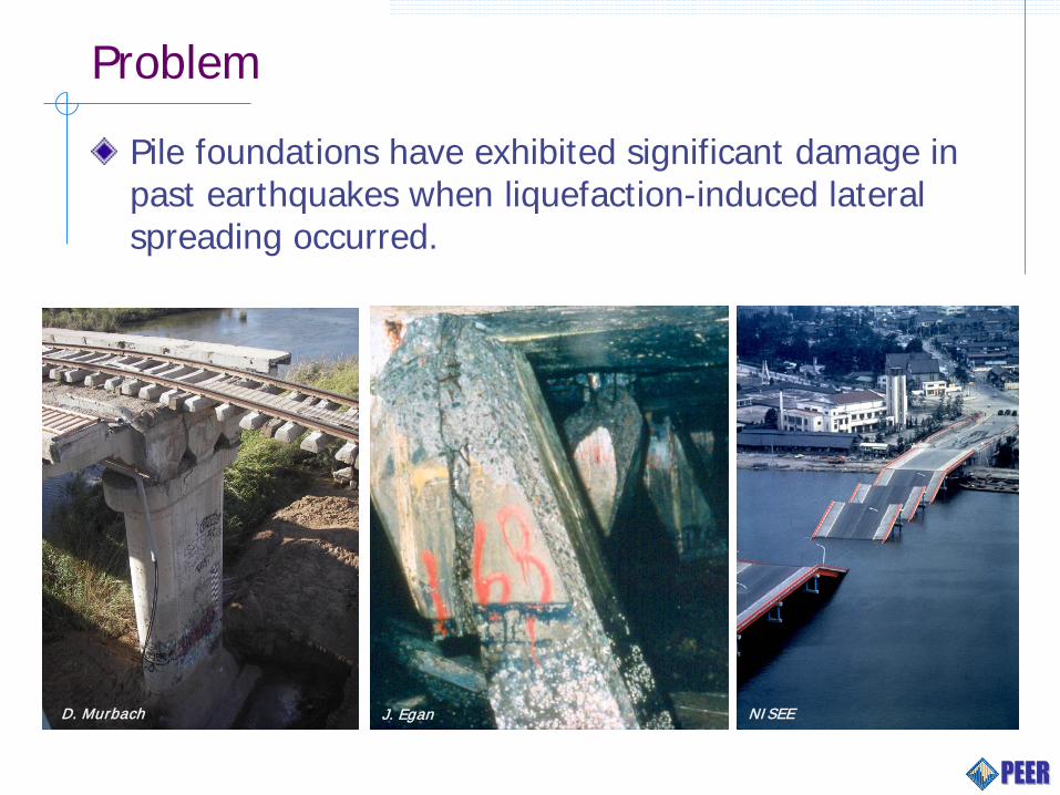
Problem
Pile foundations have exhibited significant damage in past earthquakes when liquefaction-induced lateral spreading occurred.
S. Iai J. Egan NISEE D. Murbach
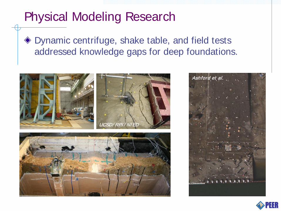
Physical Modeling Research
Dynamic centrifuge, shake table, and field tests addressed knowledge gaps for deep foundations.
UCSD/ RPI/ NIED
Ashford et al.

Simulation
Analytical tools that have been developed range from beam on springs methods to 2-D and 3-D dynamic FEM or FDM.
Free-fieldsoil column
Crust
Liquefiedsoil
Firmsoil
∆soil ∆cap
Wss
Wcap
Iss
Icap
Elgamal et al.
Arduino et al.
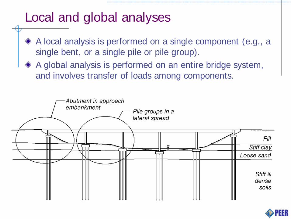
Local and global analyses
A local analysis is performed on a single component (e.g., a single bent, or a single pile or pile group). A global analysis is performed on an entire bridge system, and involves transfer of loads among components.

Equivalent Static vs Nonlinear Dynamic Analysis
Equivalent static analysis is typically performed for a single component, typically a single pile or pile group. Liquefaction-compatible inertia demands must be imposed simultaneously with kinematic demands.
Free-fieldsoil column
Crust
Liquefiedsoil
Firmsoil
∆soil ∆cap
Wss
Wcap
Iss
Icap
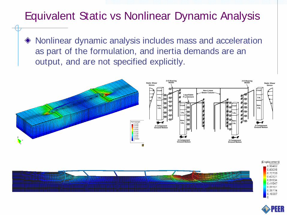
Equivalent Static vs Nonlinear Dynamic Analysis
Nonlinear dynamic analysis includes mass and acceleration as part of the formulation, and inertia demands are an output, and are not specified explicitly.
Liq.
Non-Liq.
Crust
Liq.
Non-Liq.
Crust
Liq.
Non-Liq.
Crust
Liq.
Non-Liq.
Crust
2-ComponentGround Motion
2-D BearingModel
2-D BearingModel
LiquefiableP-y Element
Static ShearStress
Static ShearStress
Non-LinearBeam Column
2-ComponentGround Motion
2-ComponentGround Motion
2-ComponentGround Motion
General Approach
Steps for design or performance evaluation of a pile foundation with liquefaction hazard include: Design/evaluate for inertia loading that would occur
in the absence of liquefaction. Evaluate the potential for liquefaction and
associated ground displacements. Design/evaluate for the lateral spreading and
inertia demands that would occur if liquefaction is triggered.
Liquefaction and Lateral Spreading Assessment
Site characterization and evaluation of liquefaction susceptibility. Evaluation of the potential for liquefaction triggering in susceptible soils. Estimation of expected lateral and vertical ground displacements or instability of embankments and slopes due to liquefaction. Estimation of vertical profile of horizontal ground displacement for input to BNWF method.
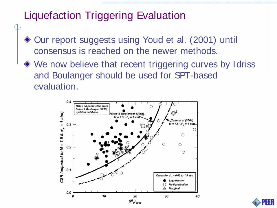
Liquefaction Triggering Evaluation
Our report suggests using Youd et al. (2001) until consensus is reached on the newer methods. We now believe that recent triggering curves by Idriss and Boulanger should be used for SPT-based evaluation.
Ground Deformations Due To Liquefaction
Instability of a slope or embankment due to shear strength loss in liquefied zones (a.k.a., flow failure). Inertia-driven horizontal displacement of level of mildly sloping ground (a.k.a., ground oscillation or lateral spreading). Settlements due to one-dimensional reconsolidation of liquefied soils, settlements of structures resting atop liquefied soils, and settlements of piles due to loss of bearing capacity and liquefaction-induced downdrag.

Liquefaction Flow Failure
Assign residual strength to soil with FSliq ≤ 1.1.
Assign full drained strength to soil with FSliq ≥ 1.3.
Linear interpolation for soils with 1.1 < FSliq < 1.3

Liquefaction Flow Failure
Selection of normalized or non-normalized curve is up to designer, but life-safety decisions should not depend on this particular selection.

Lateral Spreading Prediction
Integration of shear strain profiles estimated from SPT- and CPT-based liquefaction analysis, often called Liquefaction Displacement Index or LDI (e.g., Zhang et al. 2004, Faris et al. 2006). Empirical relationships based on regression against case history data (e.g., Youd et al. 2002, Bardet et al. 2002, Rauch and Martin 2000). Newmark sliding block analyses, including regression models and methods requiring integration of site-specific earthquake acceleration time series. Nonlinear dynamic numerical simulations, including one-dimensional site response with horizontal body stresses for sloping ground, or 2-D or 3-D nonlinear dynamic simulations.
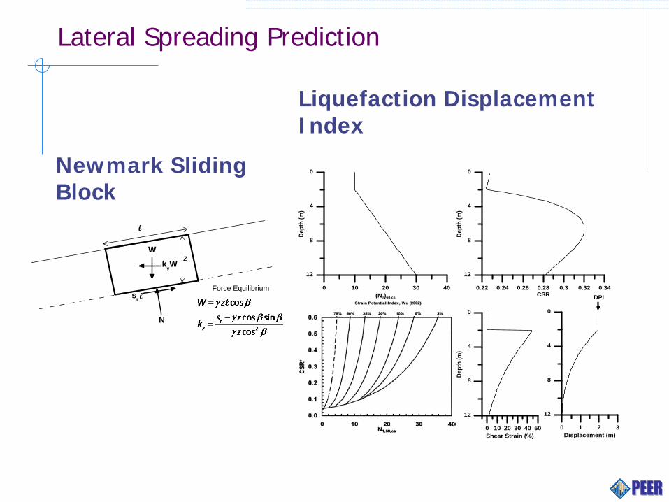
Lateral Spreading Prediction
0 10 20 30 40 50Shear Strain (%)
12
8
4
0
Dept
h (m
)
0 10 20 30 40(N1)60,cs
12
8
4
0
Dept
h (m
)
0.22 0.24 0.26 0.28 0.3 0.32 0.34CSR
12
8
4
0
Dept
h (m
)
0 1 2 3Displacement (m)
12
8
4
0
DPI
l
zW
N
sr l
kyW
Force Equilibrium
Newmark Sliding Block
Liquefaction Displacement Index

Analysis of Piles in Response to Lateral Spreading
We distinguish pile foundations supporting abutments with finite-width approach embankments from pile foundations supporting intermediate piers because of the potential for pile pinning effects at abutments.
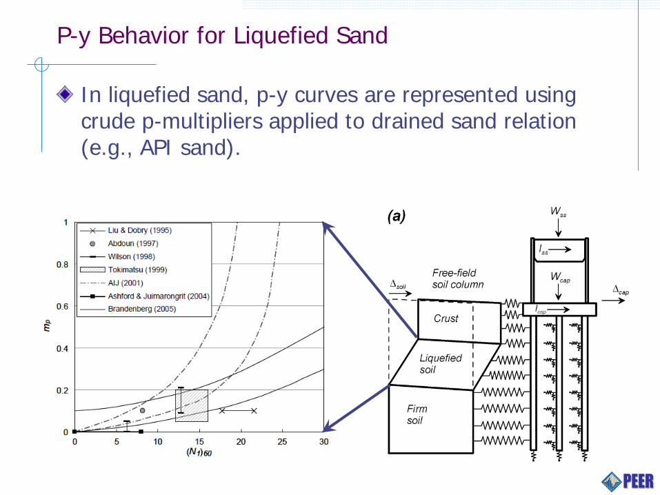
P-y Behavior for Liquefied Sand
In liquefied sand, p-y curves are represented using crude p-multipliers applied to drained sand relation (e.g., API sand).
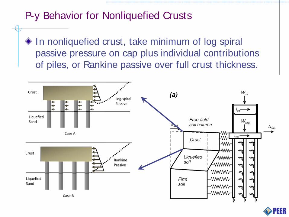
P-y Behavior for Nonliquefied Crusts
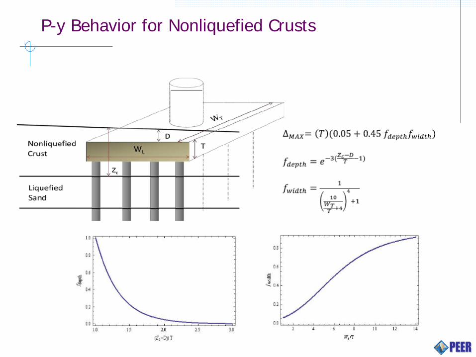
In nonliquefied crust, take minimum of log spiral passive pressure on cap plus individual contributions of piles, or Rankine passive over full crust thickness.
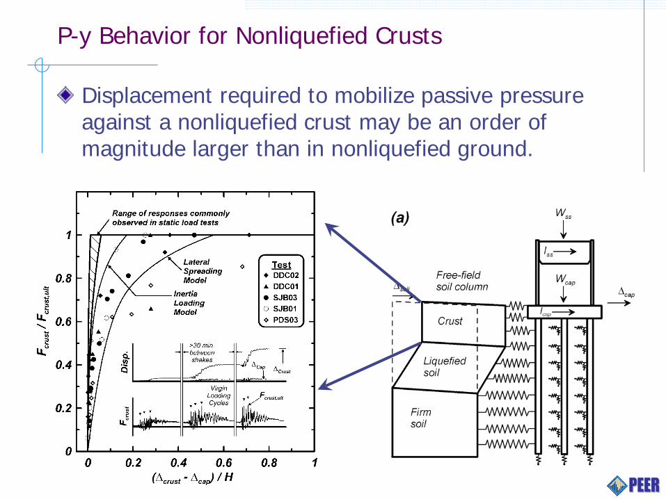
P-y Behavior for Nonliquefied Crusts
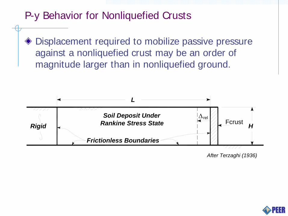
Displacement required to mobilize passive pressure against a nonliquefied crust may be an order of magnitude larger than in nonliquefied ground.
P-y Behavior for Nonliquefied Crusts
Displacement required to mobilize passive pressure against a nonliquefied crust may be an order of magnitude larger than in nonliquefied ground.
Frictionless Boundaries
Soil Deposit Under Rankine Stress State
L
H∆ rel
FcrustRigid
After Terzaghi (1936)
P-y Behavior for Nonliquefied Crusts

P-y Behavior near Layer Interfaces
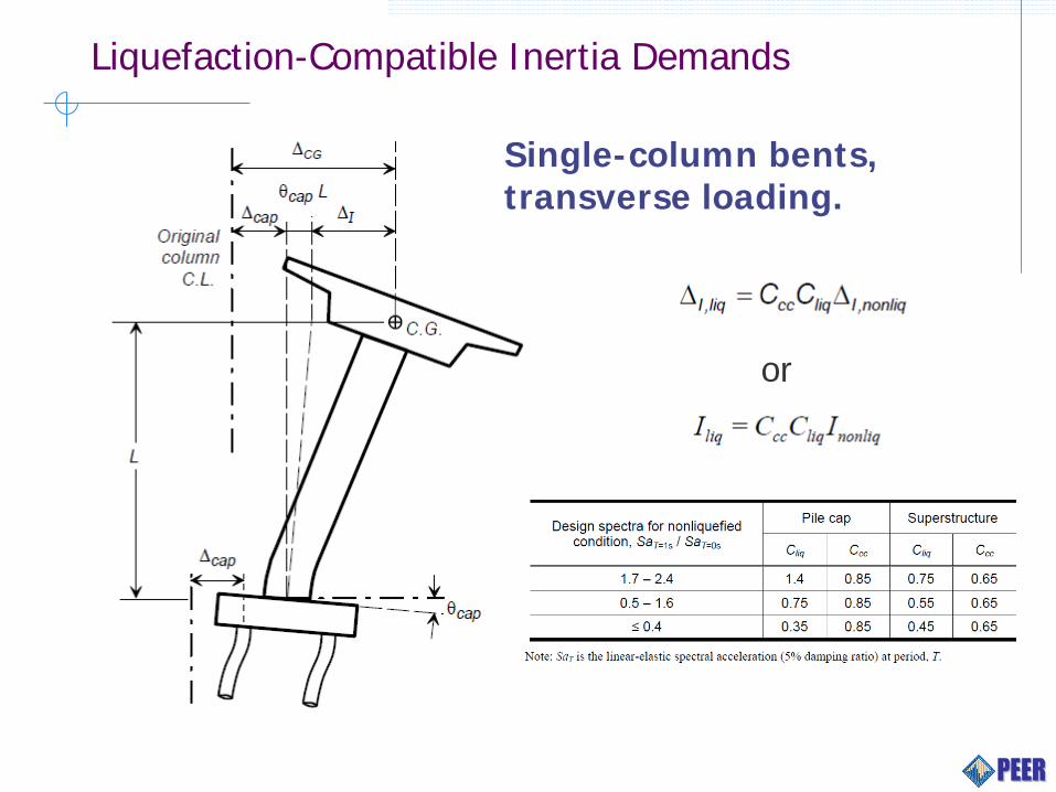
Liquefaction-Compatible Inertia Demands
or
Single-column bents, transverse loading.

Liquefaction-Compatible Inertia Demands
Longitudinal Direction.

Liquefaction-Compatible Inertia Demands
Longitudinal Direction.
Pile Pinning Effects at Approach Embankments
Estimate the longitudinal displacement of the embankment soil mass for a range of restraining forces from the piles and bridge superstructure (Slope stability analysis plus Newmark sliding block). Estimate the longitudinal restraining force exerted on the embankment mass by the piles and bridge superstructure for a range of imposed embankment displacements (Equivalent static numerical analysis). Determine the compatible displacement and interaction force between the embankment mass and the piles and bridge superstructure.
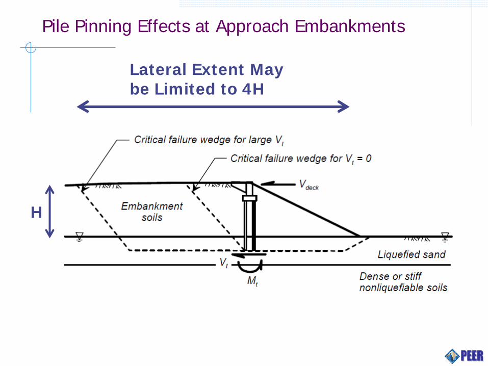
Pile Pinning Effects at Approach Embankments
Lateral Extent May be Limited to 4H
H
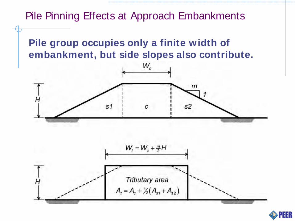
Pile Pinning Effects at Approach Embankments
Pile group occupies only a finite width of embankment, but side slopes also contribute.
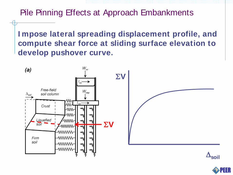
Pile Pinning Effects at Approach Embankments
Impose lateral spreading displacement profile, and compute shear force at sliding surface elevation to develop pushover curve.
ΣV
ΣV
∆soil
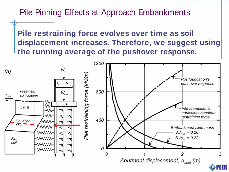
Pile Pinning Effects at Approach Embankments
Pile restraining force evolves over time as soil displacement increases. Therefore, we suggest using the running average of the pushover response.

Global Analysis

Evaluation of Guidelines by Case History Analysis
( | ) ( | ) ( | )H h H hP EDP edp Earthquake P EDP edp D d dP D d Earthquake> = > = >∫
Three case histories that exhibited various levels of performance in liquefaction-induced lateral spreading ground were analyzed.
Rather than adjusting input parameters to provide a good fit between deterministic predictions and measured performance, a uniform approach was adopted following Ashford et al. (2011).
Uncertainty was incorporated using PBEE method conditioned on the earthquake that occurred for each case using (1) liquefaction triggering evaluation, (2) lateral spreading displacement estimation, and (3) fragility function development for structural response.

Showa Bridge: Collapse
Landing Road Bridge: Moderate Damage
Leuw Mei Bridge: No Liquefaction Damage

Liquefaction Triggering Evaluation
Brandenberg et al. (2013). “Analysis of Three Bridges That Exhibited Various Performance Levels in Liquefied and Laterally Spreading Ground.” J. Geotech. Geoenviron. Eng. Published ahead of print.
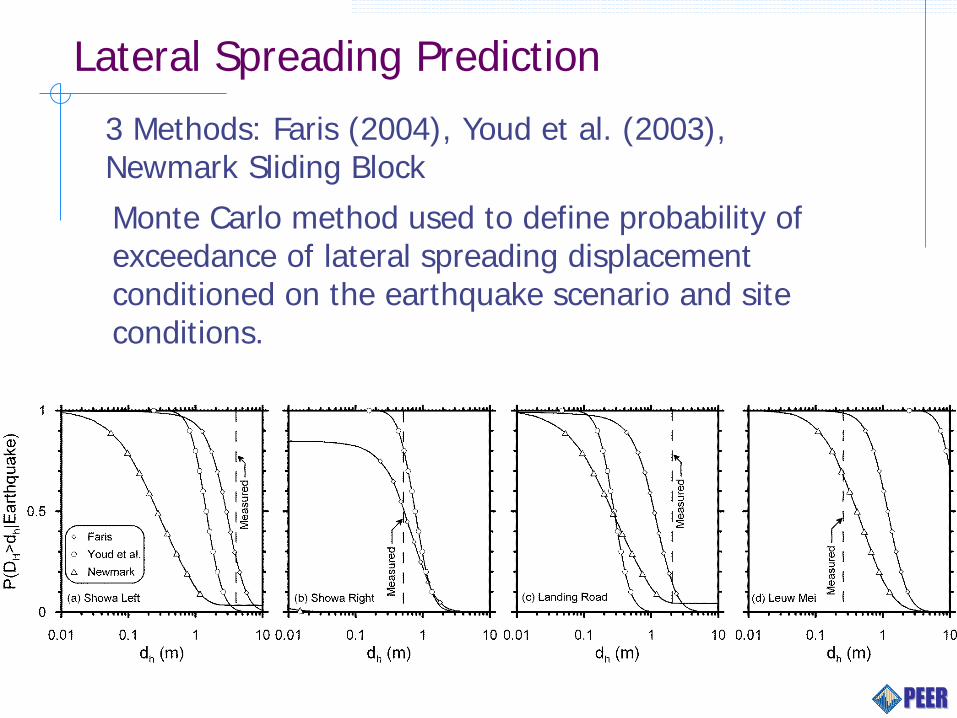
Lateral Spreading Prediction
3 Methods: Faris (2004), Youd et al. (2003), Newmark Sliding Block
Monte Carlo method used to define probability of exceedance of lateral spreading displacement conditioned on the earthquake scenario and site conditions.

Static BNWF Modeling: Showa Bridge
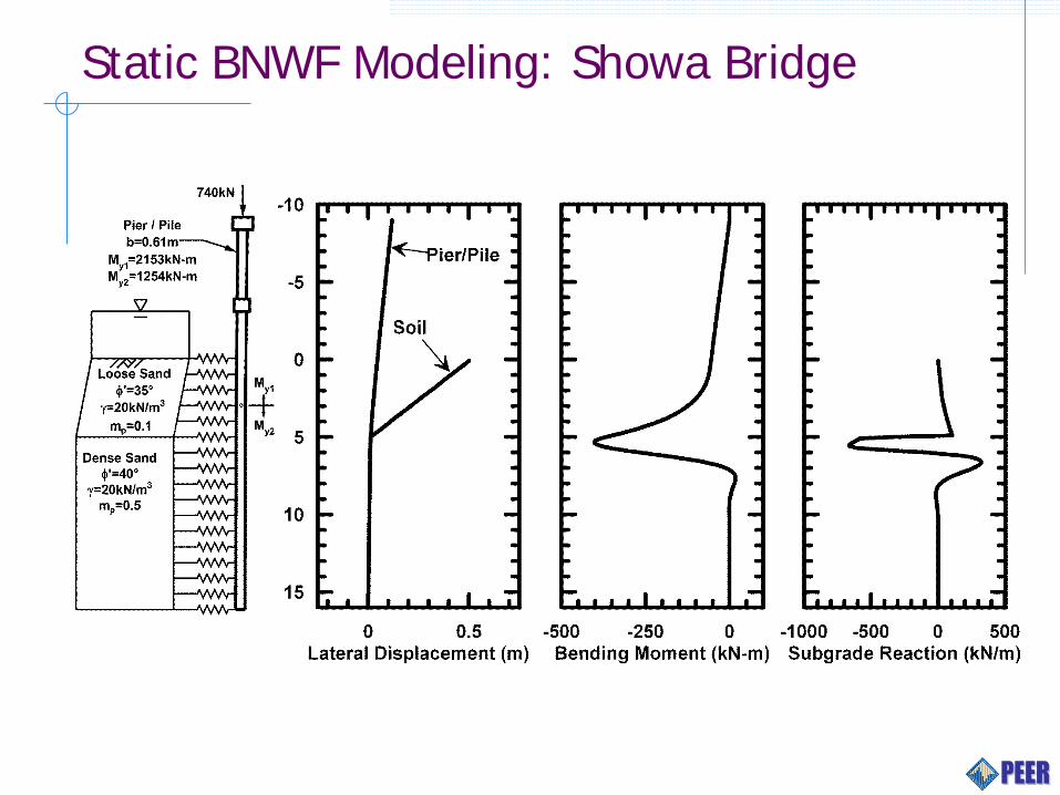
Static BNWF Modeling: Showa Bridge
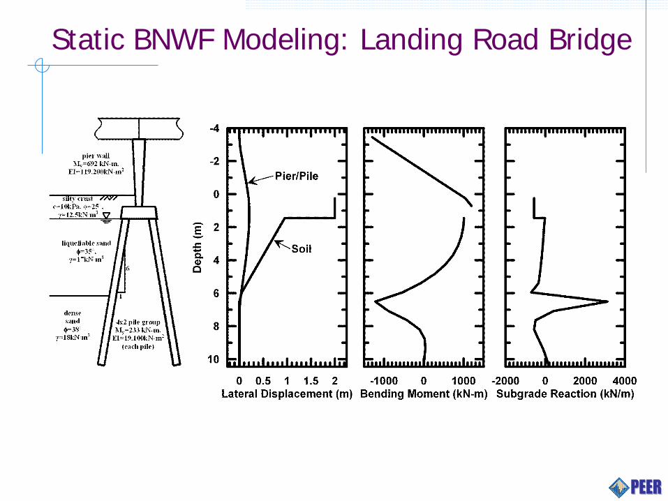
Static BNWF Modeling: Landing Road Bridge
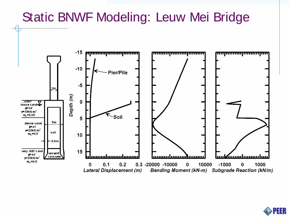
Static BNWF Modeling: Leuw Mei Bridge
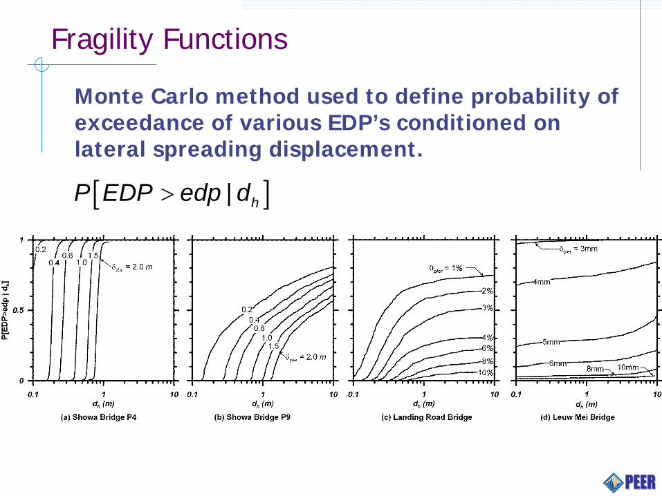
Fragility Functions
[ ]| hP EDP edp d>
Monte Carlo method used to define probability of exceedance of various EDP’s conditioned on lateral spreading displacement.
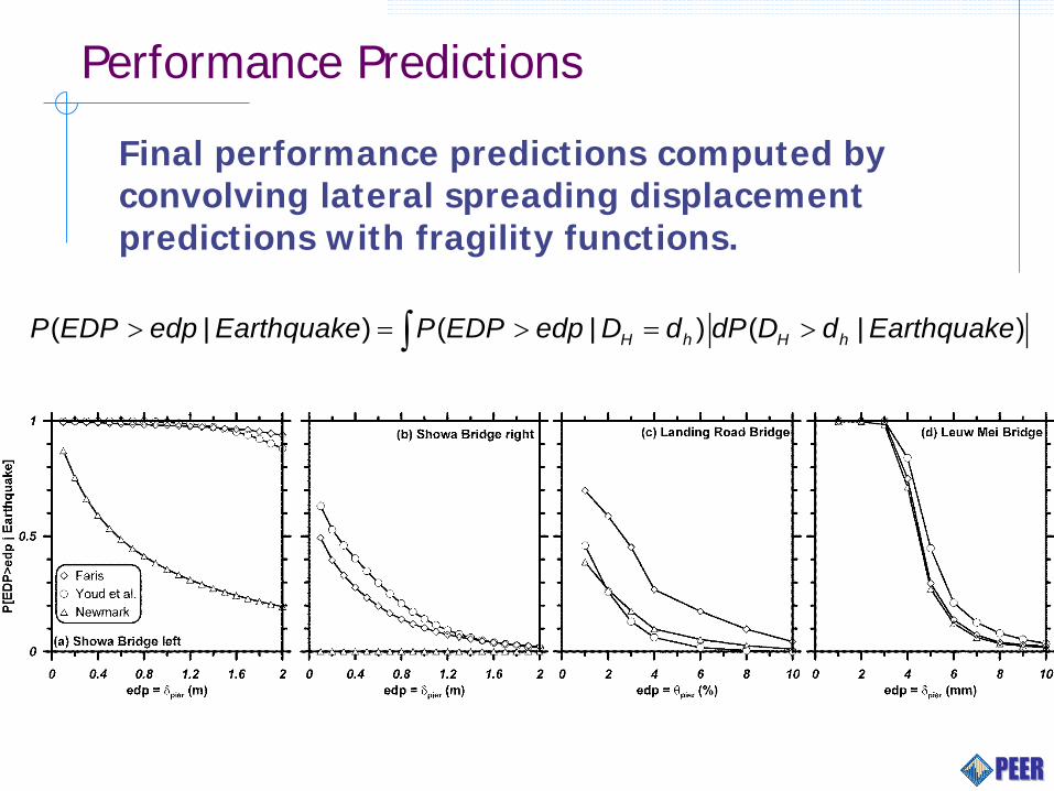
Performance Predictions
Final performance predictions computed by convolving lateral spreading displacement predictions with fragility functions.
( | ) ( | ) ( | )H h H hP EDP edp Earthquake P EDP edp D d dP D d Earthquake> = > = >∫
PEER Transportation Systems Research Program 45/19
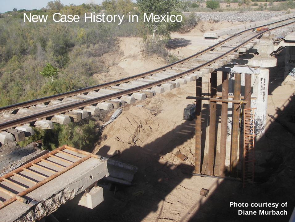
Photo courtesy of Diane Murbach
New Case History in Mexico
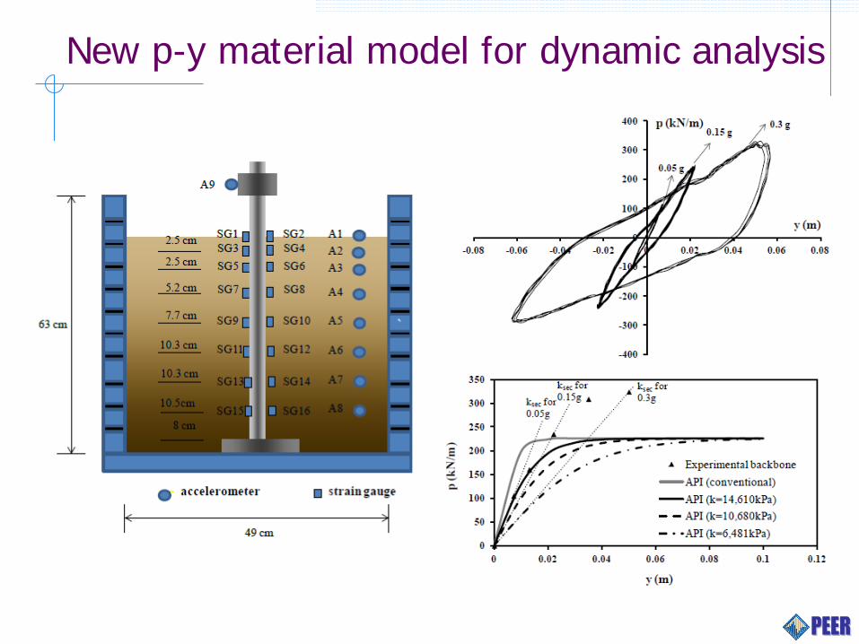
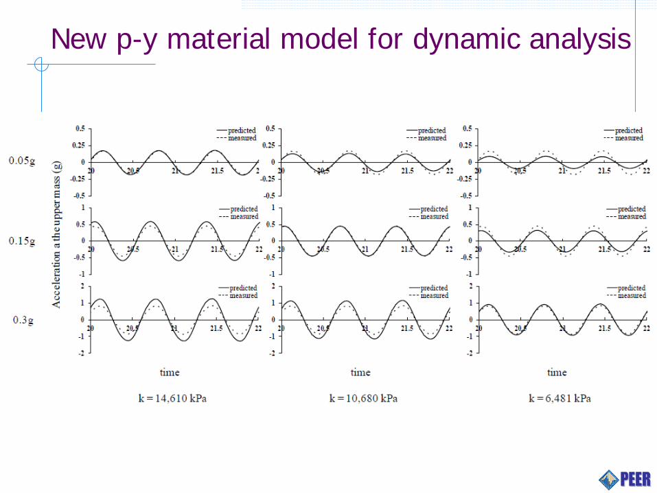
New p-y material model for dynamic analysis
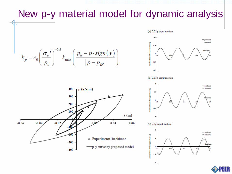
New p-y material model for dynamic analysis
New p-y material model for dynamic analysis
Conclusions
Guidelines for design of piles in liquefiable soil profiles with potential for lateral spreading are presented.
When equivalent static analysis methods are utilized, p-y materials and inertia demands must be adjusted for compatibility with liquefaction conditions.
The amount of displacement required to mobilize passive pressure in a nonliquefied crust can be an order of magnitude larger than for traditional earth pressure theory formed for nonliquefied profiles.
Conclusions
Significant uncertainty in estimating lateral spreading displacement dictates that multiple methods should be used to bound the range of predictions. Life-safety decisions should never be based on estimates from a single method.
The guidelines document (Ashford, Boulanger, and Brandenberg 2011) produced reasonable predictions of performance for three case histories that exhibited poor, mediocre, and good performance in liquefied ground.
A new p-y material developed for nonlinear dynamic analysis of piles provides better predictions than the functional forms that are commonly used (e.g., API sand).

Questions?


![Pile Foundation Design[1] - ITDmtp.itd.co.th/ITD-CP/data/PileFoundationDesign.pdf · Introduction to pile foundations Pile foundation design Load on piles Single pile design Pile](https://static.fdocuments.net/doc/165x107/5a6ffb387f8b9ab1538b8376/pile-foundation-design1-itdmtpitdcothitd-cpdatapilefoundationdesignpdfpdf.jpg)