
REC/Municipal - Amazon Simple Storage Service · 4 125 AMP–4 TERMINAL–SINGLE...
52
Meter Mounting Equipment REC/ Municipal
Transcript of REC/Municipal - Amazon Simple Storage Service · 4 125 AMP–4 TERMINAL–SINGLE...

Meter Mounting EquipmentREC/Municipal

MILBANK OVERVIEW2M
ILB
AN
K O
VER
VIE
W
2
Charles A. Milbank1879-1966
Bill Martin Robert F. Waldrop,1922-2002
Robert F. Waldrop, IIChairman
Katrina Waldrop HenkeVice Chairman
Milbank–Quality Metering Products for 80 Yearsilbank ManufacturingCompany was estab-lished in 1927 byCharles A. Milbank.
Originally, the company manu-factured high voltage switches;however, by 1941 Milbank devot-ed itself primarily to the manufac-ture of sheet metal enclosuresand related equipment for theelectrical generation and distribu-tion industry. Today we are anindustry leader in the manufac-ture of electrical meter sockets.Through a national network ofmanufacturer’s representatives weprovide wholesale electrical dis-tributors with quality electricalproducts for the utility, contractor,industrial and OEM markets.
As the meter standards havechanged, Milbank has been suc-cessful in adapting its productline to these changes. Our fullscale engineering departmentdesigns products to meet cus-tomer specifications and satisfyall utility requirements.Milbank’s employee base of over1,000 workers, along with ourfive manufacturing facilities com-
prising almost 550,000 squarefeet give us the flexibility toschedule, produce, and shiporders quickly. Currently,Milbank manufactures over10,000 different catalog items,and this list continues to grow.Our unique product offeringincludes: Residential &Commercial Meter Sockets;Residential & Commercial MeterPedestals; RV/MH Power Outlets,S e r v i ce Pede s t a l s , andTransformers; Commercial &Industrial Electrical Enclosures;Circuit Breakers; Disconnects &Safety Switches; Safety Sockets;Utility & Residential SecondaryPedestals; Hubs, and relatedaccessories. If you don’t find aunit in this catalog to service yourneeds, send us your specificationsand we will be happy to workwith you.
Our success has come from aloyal customer base that can relyon us to build quality products ata fair price in a timely manner.Our willingness and ability todesign and produce new productsto meet our customer demands is
an important factor to remaincompetitive in today’s electricalmarket.
Milbank has been serving theelectric utility & wholesale distri-bution industries for 80 yearswith innovative, quality engi-neered products. So rememberus for all of your meter mountingand related requirements, andwe will be happy to serve you aswe have in the past–with depend-able service and quality products!
We take great pride in beingone of the few family-ownedbusinesses left in our industry.We are a third generation runbusiness and truly believe that...
FAMILY MAKES A DIFFERENCE!
M

3TA
BLE O
F CO
NTEN
TSTABLE OF CONTENTS
3
SINGLE POSITION125 AMP–4 TERMINAL–RINGLESS/RING TYPE–600 VAC . . . . . . . . . . . . . . . . . . . . . . . . . . . . . . . . . . . . . . . . . . . . . . . 4200 AMP–4 TERMINAL–RINGLESS–600 VAC . . . . . . . . . . . . . . . . . . . . . . . . . . . . . . . . . . . . . . . . . . . . . . . . . . . . . . . 5-6200 AMP–4 TERMINAL–RING TYPE–600 VAC . . . . . . . . . . . . . . . . . . . . . . . . . . . . . . . . . . . . . . . . . . . . . . . . . . . . . . . . 7200 AMP–4, 5, & 7 TERMINAL–JAW CLAMPING LEVER BYPASS–RINGLESS–600 VAC . . . . . . . . . . . . . . . . . . . . . . 8200 AMP–5 TERMINAL–JAW CLAMPING LEVER BYPASS–RINGLESS–600 VAC . . . . . . . . . . . . . . . . . . . . . . . . . . . . 9320 AMP–4 & 5 TERMINAL–RINGLESS–600 VAC . . . . . . . . . . . . . . . . . . . . . . . . . . . . . . . . . . . . . . . . . . . . . . . . . . . . . 10320 AMP–4 TERMINAL–RINGLESS–600 VAC . . . . . . . . . . . . . . . . . . . . . . . . . . . . . . . . . . . . . . . . . . . . . . . . . . . . . . . . 11320 AMP–7 TERMINAL–SIDE WIREWAY–RINGLESS–600 VAC . . . . . . . . . . . . . . . . . . . . . . . . . . . . . . . . . . . . . . . . . 12
METER MAINS100 AMP–4 TERMINAL–RING TYPE–METER MAIN . . . . . . . . . . . . . . . . . . . . . . . . . . . . . . . . . . . . . . . . . . . . . . . . . . . 13100 & 200 AMP–4 TERMINAL–RINGLESS–METER MAIN–LOAD SIDE DISTRIBUTION . . . . . . . . . . . . . . . . . . . . . . . 14200 AMP–4 TERMINAL–RINGLESS–METER MAIN WITH BREAKERS . . . . . . . . . . . . . . . . . . . . . . . . . . . . . . . . . . . . 15200 AMP–4 TERMINAL–RINGLESS–METER MAIN–22K AIC . . . . . . . . . . . . . . . . . . . . . . . . . . . . . . . . . . . . . . . . . . . . 16200 AMP–4 TERMINAL–RINGLESS–METER MAIN . . . . . . . . . . . . . . . . . . . . . . . . . . . . . . . . . . . . . . . . . . . . . . . . . . . . 17320 AMP–4 TERMINAL–RINGLESS–METER MAIN–SIDE WIREWAY–WITH BREAKERS . . . . . . . . . . . . . . . . . . . 18-19200 AMP–4 TERMINAL–RING TYPE–METER MAIN . . . . . . . . . . . . . . . . . . . . . . . . . . . . . . . . . . . . . . . . . . . . . . . . . . . 20200 AMP–4 & 5 TERMINAL–RINGLESS–METER MAIN–JAW CLAMPING–AUXILIARY POWER CENTER . . . . . . . . 21
CT RATED20 AMP–13 TERMINAL–RINGLESS/RING TYPE–TRANSFORMER RATED . . . . . . . . . . . . . . . . . . . . . . . . . . . . . . . . 2220 AMP–13 TERMINAL– RINGLESS–TRANSFORMER RATED–600 VAC . . . . . . . . . . . . . . . . . . . . . . . . . . . . . . . . . . 2320 & 80 AMP–13 TERMINAL–RINGLESS–JAW CLAMPING LEVER BYPASS–TRANSFORMER RATED . . . . . . . . . . 24400 AMP–6, 8 & 13 TERMINAL–TRANSOCKET FOR USE WITH BAR TYPE CTS . . . . . . . . . . . . . . . . . . . . . . . . . . . . 25600 AMP–6, 8, 13 & 14 TERMINAL–COMMERCIAL TRANSOCKET PTS, DONUT OR BAR TYPE . . . . . . . . . . . . . . . 261200–1600 AMP–MAXI–TRANSOCKET WITH PTS AND BAR TYPE CTS . . . . . . . . . . . . . . . . . . . . . . . . . . . . . . . . . . 27
PEDESTALS/METER MAINS100/200 AMP–4 TERMINAL–METER MAIN PEDESTAL–1Ø–120/240 VAC . . . . . . . . . . . . . . . . . . . . . . . . . . . . . . . . . 28320 AMP–4 TERMINAL–METER PEDESTAL WITH LEVER BYPASS . . . . . . . . . . . . . . . . . . . . . . . . . . . . . . . . . . . . . . 29480 AMP CONTINUOUS–4 TERMINAL–K SERIES METER MAIN . . . . . . . . . . . . . . . . . . . . . . . . . . . . . . . . . . . . . . . . . 30100/200 AMP–4 TERMINAL–RESIDENTIAL PEDESTAL–SINGLE OR DOUBLE POSITION–1Ø3W–600VAC . . . . . . 31200 AMP–RINGLESS–METERED PEDESTALS . . . . . . . . . . . . . . . . . . . . . . . . . . . . . . . . . . . . . . . . . . . . . . . . . . . . 32-33U5706 & U5707 TEMP TO FINAL SERVICE PEDESTAL–RINGLESS/RING TYPE . . . . . . . . . . . . . . . . . . . . . . . . . 34-35200 AMP–4 TERMINAL–MOBILE HOME METER PEDESTALS–RINGLESS–120/240VAC . . . . . . . . . . . . . . . . . . . . . 36100, 200 & 400 AMP–TERMINAL BOX–1Ø & 3Ø–120/240 VOLT–600 VAC . . . . . . . . . . . . . . . . . . . . . . . . . . . . . . . . . 37
ENCLOSURESCT3R – CURRENT TRANSFORMER CABINET/PANEL ENCLOSURE–TYPE 3R . . . . . . . . . . . . . . . . . . . . . . . . . . . . 38
MISCELLANEOUSACCESSORIES . . . . . . . . . . . . . . . . . . . . . . . . . . . . . . . . . . . . . . . . . . . . . . . . . . . . . . . . . . . . . . . . . . . . . . . . . . . . . . 39-40UQFP PLUG–IN SERIES CIRCUIT BREAKERS . . . . . . . . . . . . . . . . . . . . . . . . . . . . . . . . . . . . . . . . . . . . . . . . . . . . . . . 41UQFB BOLT–ON SERIES CIRCUIT BREAKERS . . . . . . . . . . . . . . . . . . . . . . . . . . . . . . . . . . . . . . . . . . . . . . . . . . . . . . 42CONDUIT & AMPACITY INFORMATION . . . . . . . . . . . . . . . . . . . . . . . . . . . . . . . . . . . . . . . . . . . . . . . . . . . . . . . . . . . . . 43ENERGIZATION OF ELECTRICAL EQUIPMENT . . . . . . . . . . . . . . . . . . . . . . . . . . . . . . . . . . . . . . . . . . . . . . . . . . . . . . 44MATERIALS AND FINISHES . . . . . . . . . . . . . . . . . . . . . . . . . . . . . . . . . . . . . . . . . . . . . . . . . . . . . . . . . . . . . . . . . . . . . . 45METER FORMS . . . . . . . . . . . . . . . . . . . . . . . . . . . . . . . . . . . . . . . . . . . . . . . . . . . . . . . . . . . . . . . . . . . . . . . . . . . . . . . . 46WATTHOUR METER FORMS–STD FORMS–TRANSFORMER RATED OR SELF–CONTAINED . . . . . . . . . . . . . . . . 47STANDARD NEMA CONFIGURATIONS . . . . . . . . . . . . . . . . . . . . . . . . . . . . . . . . . . . . . . . . . . . . . . . . . . . . . . . . . . . . . 48INDEX . . . . . . . . . . . . . . . . . . . . . . . . . . . . . . . . . . . . . . . . . . . . . . . . . . . . . . . . . . . . . . . . . . . . . . . . . . . . . . . . . . . . . . . . 49ADDITIONAL MILBANK PRODUCTS . . . . . . . . . . . . . . . . . . . . . . . . . . . . . . . . . . . . . . . . . . . . . . . . . . . . . . . . . . . . . . . 50

125 AMP–4 TERMINAL–SINGLE POSITION–RINGLESS / RING TYPE–600 VAC412
5 A
MP–
4 TE
RM
INA
L–SI
NG
LE P
OSI
TIO
N–R
ING
LESS
/ R
ING
TY
PE–6
00 V
AC
Utility requirements for this equipment may vary. Always consult the serving utility for their requirements before ordering orinstalling equipment in this catalog.
4
FIFTH TERMINAL: For field mounted fifth terminal on the U7487 & U7490 order catalog number 5T8K2 to fit into roundopening at the 9 oʼclock position.
HUBS: For proper hub selection see the hub suffix chart on the accessory page.CONNECTORS: Extruded aluminum connectors are tin plated.SEALING RINGS: Ring type units supplied with an MR-2 snap action sealing ring as standard.BYPASS: Horn type bypass is available. Add suffix -KK to U7487.
1 2
34 45 6
AMP SERVICE CATALOGNUMBER
HUB CONNECTORSCU/AL
DIMENSIONS CONCENTRIC K.O.ʼS
1 2 3 4 5 6D" W" H"
125 OH/UG U7490-RL-TG H.O. 11⁄2 11⁄2 2 11⁄4 — 1⁄48 111⁄2#6-2/0
7490
U7490-RL-TG
AMP SERVICE CATALOGNUMBER
HUB CONNECTORSCU/AL
DIMENSIONS CONCENTRIC K.O.ʼS
1 2 3 4 5 6D" W" H"
125 OH/UG U7487-RL-TG H.O. 11⁄2 11⁄2 2 11⁄4 — 1⁄48 111⁄2#6-2/0
125 AMP–SINGLE POSITION–4 TERMINAL–RINGLESS
1 2
34 45 6
7487
U7487-RL-TG
125 AMP–SINGLE POSITION–4 TERMINAL–RING TYPE
35⁄16
35⁄16
5200 A
MP–4 TER
MIN
AL–R
ING
LESS–600 VA
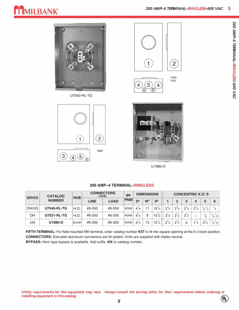
C200 AMP–4 TERMINAL–RINGLESS–600 VAC
Utility requirements for this equipment may vary. Always consult the serving utility for their requirements before ordering orinstalling equipment in this catalog.
5
SERVICE CATALOGNUMBER
HUBCONNECTORS
CU/AL
LINE LOAD
BY-PASS
DIMENSIONS CONCENTRIC K.O.ʼS
1 2 3 4 5 6D" W" H"
OH/UG U7040-RL-TG H.O. NONE 21⁄2 21⁄2 21⁄2 21⁄2 1⁄4,1⁄2 1⁄441⁄8 11 151⁄2#6-350 #6-350
OH U7021-RL-TG H.O. NONE 21⁄2 21⁄2 21⁄2 – 1⁄4 1⁄4,1⁄241⁄8 8 151⁄2#6-350 #6-350
200 AMP–4 TERMINAL–RINGLESS
FIFTH TERMINAL: For field mounted fifth terminal, order catalog number K5T to fit into square opening at the 9 oʼclock position.CONNECTORS: Extruded aluminum connectors are tin plated. Units are supplied with triplex neutral.BYPASS: Horn type bypass is available. Add suffix -KK to catalog number .
U7040-RL-TG
1
553 4
6
2
4
UG BLANK NONE 21⁄2 21⁄2 3 11⁄2 21⁄2 1⁄4,1⁄241⁄2 13 151⁄4#6-350 #6-350U1980-O
U1980-O
2
43
1
65
1980
70407021

620
0 A
MP–
4 TE
RM
INA
L–R
ING
LESS
–600
VA
C
Utility requirements for this equipment may vary. Always consult the serving utility for their requirements before ordering orinstalling equipment in this catalog.
6
200 AMP–4 TERMINAL–RINGLESS–600 VAC
U4532-XL
CATALOGNUMBER
HUBCONNECTORS
CU/AL
LINE LOAD
BY-PASS
DIMENSIONS CONCENTRIC K.O.ʼS
1 2 3 4 5 6D" W" H"
U4532-XL C.P NONE 21⁄2 21⁄2 3 31⁄4 1⁄4,
1⁄247⁄8 15 201⁄2#6-350DUAL#6-350
U7043-XL-TG C.P NONE 21⁄2 21⁄2 3 31⁄4 1⁄4,
1⁄247⁄8 13 151⁄2#6-350 #6-350
200 AMP—4 TERMINAL—OVERHEAD / UNDERGROUND—RINGLESS
FIFTH TERMINAL: For field mounted fifth terminal order catalog number K5T.CONNECTORS: Extruded aluminum connectors are tin plated.
U7043-XL-TG
1
553 4
6
2
445327043

7200 A
MP–4 TER
MIN
AL–R
ING
TYPE–600 V
AC
200 AMP–4 TERMINAL–RING TYPE–600 VAC
Utility requirements for this equipment may vary. Always consult the serving utility for their requirements before ordering orinstalling equipment in this catalog.
7
345
1
3 4
2
45 6
U7017-RL-TG U7018-XL-TG
7017
7018
SERVICE CATALOGNUMBER
HUB
OH U7017-RL-TG H.O.
CONNECTORSCU/AL
LINE LOAD
BY-PASS
NONE
DIMENSIONS CONCENTRIC K.O.ʼS
1 2 3 4 5 6
21⁄2 21⁄2 21⁄2 — 1⁄4 1⁄4,1⁄2
D" W" H"
41⁄8 8 151⁄2#6-350 #6-350
OH/UG U7018-XL-TG C.P. NONE 21⁄2 21⁄2 21⁄2 21⁄2 1⁄4,1⁄2 1⁄441⁄8 11 151⁄2#6-350 #6-350
200 AMP–4 TERMINAL—RING TYPE
HUBS: For proper hub selection see the hub suffix chart below or accessory section.FIFTH TERMINAL: For field mounted fifth terminal order catalog number K5T.CONNECTORS: Extruded aluminum internal hex lay-in type connectors are tin plated. Units are supplied with duplex neutral.TRIPLEX GROUND (-TG): Factory installed.SEALING RINGS: Ring type units are supplied with MR-2, snap action, sealing rings as standard.
1" -WL
SIZE SUFFIXMILBANK CAT. NO.
-YL-ZL-DL-EL
A7514A7515
11⁄2" A75162" A7517
21⁄2" A7518
INTERCHANGEABLE UNIT HUBS
11⁄4"
200 AMP–4, 5 & 7 TERMINAL–SINGLE POSITION–RINGLESSJAW CLAMPING LEVER BYPASS–600 VAC8
200
AM
P–4,
5 &
7 T
ERM
INA
L–SI
NG
LE P
OSI
TIO
N–R
ING
LESS
JAW
CLA
MPI
NG
LEV
ER B
YPA
SS–6
00 V
AC
Utility requirements for this equipment may vary. Always consult the serving utility for their requirements before ordering orinstalling equipment in this catalog.
8
200 AMP—5 TERMINAL—RINGLESS—1∅3W OR 3∅3W
SERVICE CATALOGNUMBER
HUB
OH
OH/UG
U9550-RRL
U9551-RXL
H.O.
C.P.
CONNECTORSCU/AL
BY-PASS
LEVER
LEVER
DIMENSIONS CONCENTRIC K.O.ʼS
1 2 3 4 5 6
3
3
21⁄2
21⁄2
3
3
—3
1⁄4,1⁄2
1⁄4
3⁄41⁄4,
1⁄2
D" W" H"
47⁄8
47⁄8
10
13
181⁄2
19
#6-350
#6-350
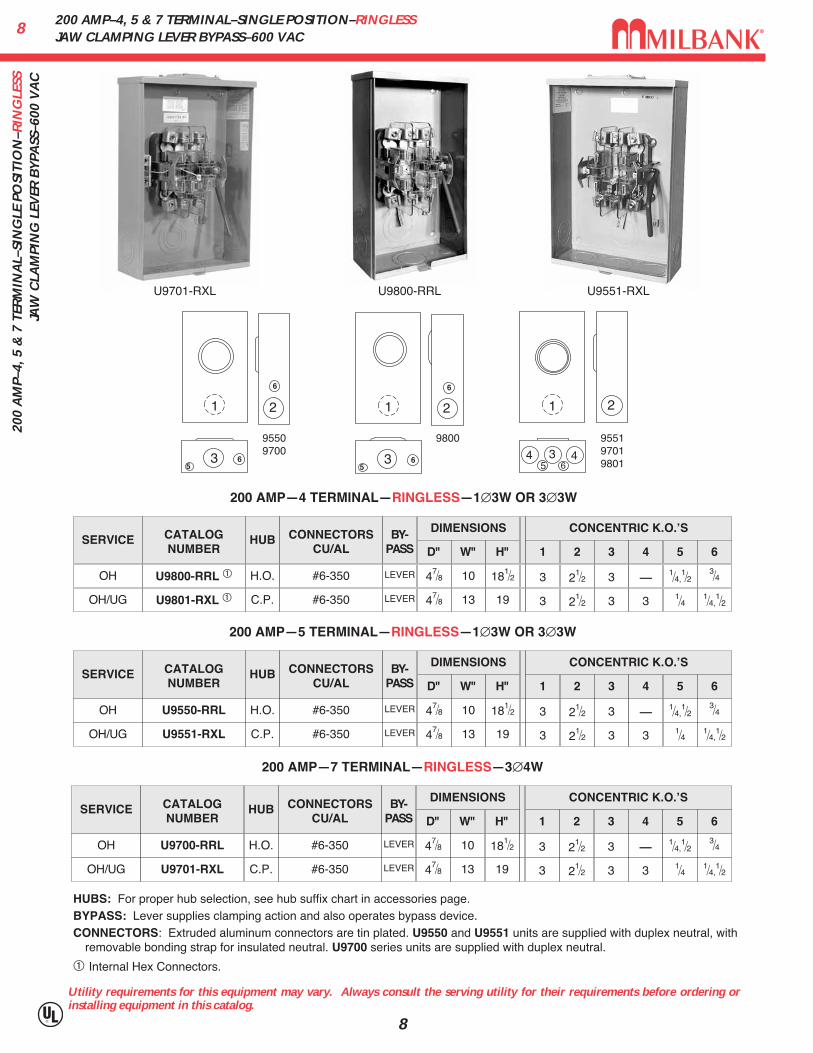
200 AMP—4 TERMINAL—RINGLESS—1∅3W OR 3∅3W
SERVICE CATALOGNUMBER
HUB
OH
OH/UG
U9800-RRL �
U9801-RXL �
H.O.
C.P.
CONNECTORSCU/AL
BY-PASS
LEVER
LEVER
DIMENSIONS CONCENTRIC K.O.ʼS
1 2 3 4 5 6
3
3
21⁄2
21⁄2
3
3
—3
1⁄4,1⁄2
1⁄4
3⁄41⁄4,
1⁄2
D" W" H"
47⁄8
47⁄8
10
13
181⁄2
19
#6-350
#6-350
200 AMP—7 TERMINAL—RINGLESS—3∅4W
SERVICE CATALOGNUMBER
HUB
OH
OH/UG
U9700-RRL
U9701-RXL
H.O.
C.P.
CONNECTORSCU/AL
BY-PASS
LEVER
LEVER
DIMENSIONS CONCENTRIC K.O.ʼS
1 2 3 4 5 6
3
3
21⁄2
21⁄2
3
3
—3
1⁄4,1⁄2
1⁄4
3⁄41⁄4,
1⁄2
D" W" H"
47⁄8
47⁄8
10
13
181⁄2
19
#6-350
#6-350
1
553 4
6
2
4
955197019801
HUBS: For proper hub selection, see hub suffix chart in accessories page.BYPASS: Lever supplies clamping action and also operates bypass device.CONNECTORS: Extruded aluminum connectors are tin plated. U9550 and U9551 units are supplied with duplex neutral, with
removable bonding strap for insulated neutral. U9700 series units are supplied with duplex neutral.
� Internal Hex Connectors.
U9701-RXL U9551-RXL
1 2
35
6
6
95509700
U9800-RRL
1 2
35
6
6
9800

9200 A
MP–5 TER
MIN
AL–
SING
LE POSITIO
NJA
W C
LAM
PING
LEVER
BY
PASS–
RIN
GLESSS–600 V
AC
200 AMP–5 TERMINAL– SINGLE POSITIONJAW CLAMPING LEVER BYPASS– RINGLESSS–600 VAC
Utility requirements for this equipment may vary. Always consult the serving utility for their requirements before ordering orinstalling equipment in this catalog.
9
U9581-RXL-QG
1
553 4
6
2
49581
200 AMP—5 TERMINAL—RINGLESS—1∅3W OR 3∅3W
SERVICE CATALOGNUMBER
HUB
OH/UG U9581-RXL-QG C.P.
CONNECTORSCU/AL
BY-PASS
LEVER
DIMENSIONS CONCENTRIC K.O.ʼS
1 2 3 4 5 6
3 21⁄2 3 3 1⁄4 1⁄4,1⁄2
D" W" H"
47⁄8 13 19#6-350
NEUTRAL DISCONNECT: The U9581 has a manual neutral disconnect bolt.HUBS: For proper hub selection, see hub suffix chart in Accessories.BYPASS: Lever supplies clamping action on meter spades and also operates 200 Amp continuous duty
bypass device.CONNECTORS: Extruded aluminum connectors are tin plated. Units are supplied with duplex neutral, with
removable bonding strap for insulated neutral.
1032
0 A
MP–
4 &
5 T
ERM
INA
L–H
EAV
Y D
UTY
LEV
ER B
YPA
SS–R
ING
LESS
–600
VA
C
Utility requirements for this equipment may vary. Always consult the serving utility for their requirements before ordering orinstalling equipment in this catalog.
10
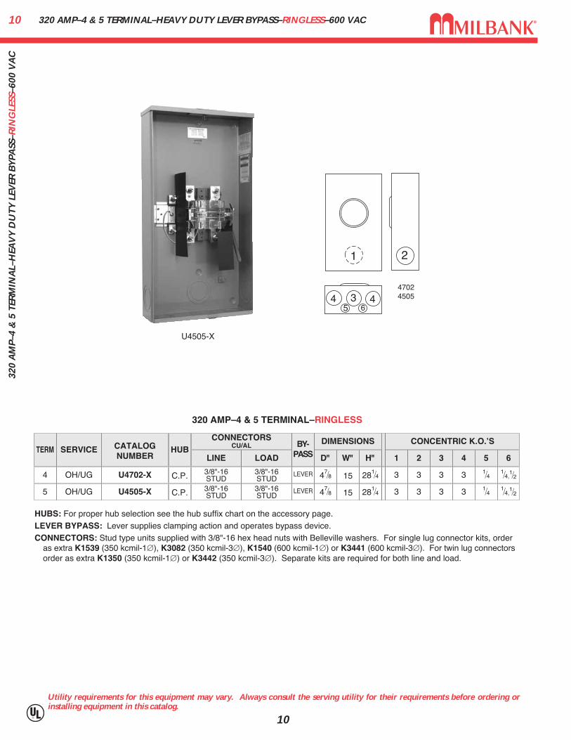
47024505
1
553 4
6
2
4
TERM SERVICE CATALOGNUMBER
HUBCONNECTORS
CU/AL
LINE LOAD
BY-PASS
DIMENSIONS CONCENTRIC K.O.ʼS
1 2 3 4 5 6D" W" H"
4 OH/UG U4702-X C.P. LEVER 3 3 3 3 1⁄4 1⁄4,1⁄247⁄8 15 281⁄43/8"-16
STUD3/8"-16STUD
5 OH/UG U4505-X C.P. LEVER 3 3 3 3 1⁄4 1⁄4,1⁄247⁄8 15 281⁄43/8"-16
STUD3/8"-16STUD
320 AMP–4 & 5 TERMINAL–RINGLESS
HUBS: For proper hub selection see the hub suffix chart on the accessory page.LEVER BYPASS: Lever supplies clamping action and operates bypass device.CONNECTORS: Stud type units supplied with 3/8"-16 hex head nuts with Belleville washers. For single lug connector kits, order
as extra K1539 (350 kcmil-1∅), K3082 (350 kcmil-3∅), K1540 (600 kcmil-1∅) or K3441 (600 kcmil-3∅). For twin lug connectorsorder as extra K1350 (350 kcmil-1∅) or K3442 (350 kcmil-3∅). Separate kits are required for both line and load.
320 AMP–4 & 5 TERMINAL–HEAVY DUTY LEVER BYPASS–RINGLESS–600 VAC
U4505-X

11320 A
MP–4 TER
MIN
AL–SIN
GLE PO
SITION
–RIN
GLESS–600 V
AC
320 AMP–4 TERMINAL–SINGLE POSITION–RINGLESS–600 VAC
Utility requirements for this equipment may vary. Always consult the serving utility for their requirements before ordering orinstalling equipment in this catalog.
11
TWIN#6-350
HUBS: For proper hub selection, see hub suffix chart in accessories page.BYPASS: Lever supplies clamping action and also operates bypass device on the U1079 & U1797.CONNECTOR KITS: Stud type units are supplied with 3⁄8"-16 hex head nuts with Belleville washers. Order two connector kits
to cover both line and load. Order K1539 (single #350), K1540 (single #600) or K1350 (twin #350). See accessories page.FIFTH TERMINAL: For field mounted fifth terminal, order as extra K3866 for the U1079. Order as extra K3865 for U1797-0.LUG SIZE RANGE: See accessories page for lug size range for U1797 units.
320 AMP–4 TERMINAL–RINGLESS–600 VAC
SVC. CATALOGNUMBER
HUB
OH U1079-R H.O.
CONNECTORSCU/AL
LINE LOADBY-
PASS
LEVER
DIMENSIONS CONCENTRIC K.O.ʼS
1 2 3 4 5 6
3 21⁄2 3 3 1⁄4 1⁄4,1⁄2
D" W" H"
47⁄8 13 383⁄43⁄8"-16 STUDS
UG U1797-O-K3L-K2L
FIFTHTERM.
K3866
K3865 BLANK LEVER 3 3 3 3 1⁄4 1⁄4,1⁄247⁄8 15 30#4-600 or
(2) 1/0-2503/8"-16STUDOH U1779-RRL-K3-K2 –– H.O. LEVER 3 21⁄2 3 3 1⁄4 1⁄4,
1⁄247⁄8 13 383⁄4#4-600 or(2) 1/0-250
2
346
45
1
1797
1
65
3 3 4
2
1079
U1797-O-K3L-K2L
U1079-R
400 AMP MAX320 AMP CONTINUOUS
1232
0 A
MP–
7 TE
RM
INA
L–SI
NG
LE P
OSI
TIO
N–R
ING
LESS
–600
VA
C
Utility requirements for this equipment may vary. Always consult the serving utility for their requirements before ordering orinstalling equipment in this catalog.
12
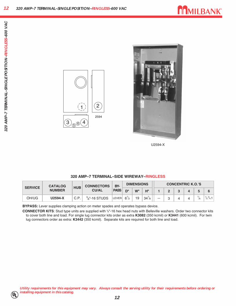
320 AMP–7 TERMINAL–SINGLE POSITION–RINGLESS–600 VAC
1 2
3 45 6
2594
U2594-X
BYPASS: Lever supplies clamping action on meter spades and operates bypass device.CONNECTOR KITS: Stud type units are supplied with 3⁄8"-16 hex head nuts with Belleville washers. Order two connector kits
to cover both line and load. For single lug connector kits order as extra K3082 (350 kcmil) or K3441 (600 kcmil). For twinlug connectors order as extra: K3442 (350 kcmil). Separate kits are required for both line and load.
320 AMP–7 TERMINAL–SIDE WIREWAY–RINGLESS
SERVICE CATALOGNUMBER
HUB CONNECTORSCU/AL
BY-PASS
DIMENSIONS CONCENTRIC K.O.ʼS
1 2 3 4 5 6D" W" H"
OH/UG U2594-X C.P. LEVER — 3 4 41⁄4 1⁄2,
3⁄4,161⁄2 19 341⁄83⁄8"-16 STUDS

13100 A
MP–4 TER
MIN
AL–M
ETER M
AIN
S–RIN
GLESS/R
ING
TYPE
100 AMP–4 TERMINAL–METER MAINS–RINGLESS/RING TYPE
Utility requirements for this equipment may vary. Always consult the serving utility for their requirements before ordering orinstalling equipment in this catalog.
13
1 1 2
345 6
4
3499
U3499-XL-100OH/UG C.P. NONE 2 2 2 2 –33⁄4 11 22#6-2/0 #6-1/0 1⁄4,1⁄2
SERVICE CATALOGNUMBER
HUBCONNECTOR
CU/AL BY-PASS
DIMENSIONS CONCENTRIC K.O.ʼS
1 2 3 4 5D" W" H"LINE LOAD 6AMPS
100
U3499-RLOH/UG H.O. NONE 2 2 2 2 –33⁄4 11 22#6-2/0 #14-1/0 1⁄4,1⁄2100
4 TERMINAL–METER MAIN–RINGLESS–1∅3W
FIFTH TERMINAL: For field installed fifth terminal on U3499, order catalog number 5T8K2 (9 oʼclock position only). HUBS: For proper hub selection refer to the hub suffix chart on the Accessory page.FACTORY INSTALLED CIRCUIT BREAKERS: The U3499-XL-100 has a factory installed 2 pole 100 amp breaker.
U8144-XL
1 1
3
2
4 45
8144
CATALOGNUMBER
U8144-XL
HUB
H.O.
CONNECTOR CU/AL BY-
PASS
NONE
DIMENSIONS CONCENTRIC K.O.ʼS
1
2 2 2 2 1⁄4,1⁄2
2 3 4 5D"
33⁄4
W"
11
H"
22
LINE
#6-2/0
LOAD
C/B
AMPS
100
SERVICE
OH/UG
4 TERMINAL–METER MAIN–RING TYPE–1∅3W
HUBS: For proper hub selection refer to the hub suffix chart on the accessory page.SEALING RINGS: Ring type units priced with MR-2 sealing ring. See accessory page for other choices.BREAKERS: The U8144 does not come with breakers unless specified on order and requires plug-in style.
CUTLER-HAMMER
QUICKLAG P BR
SIEMENS
QP
SQUARE D
HOMELINE
GENERALELECTRIC
Q LINE
AMPS
0-100
BREAKER COMPATIBILITY CHART
U3499-XL
100 & 200 AMP–4 TERMINAL–METER MAIN–RINGLESSWITH LOAD SIDE DISTRIBUTION–120 / 240 VAC14
100
& 2
00 A
MP–
4 TE
RM
INA
L–M
ETER
MA
IN–R
ING
LESS
WIT
H L
OA
D S
IDE
DIS
TRIB
UTI
ON
–120
/ 2
40 V
AC
Utility requirements for this equipment may vary. Always consult the serving utility for their requirements before ordering orinstalling equipment in this catalog.
14
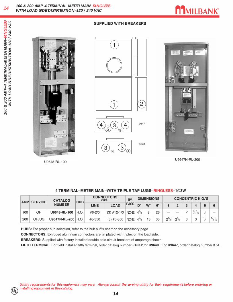
CONNECTORSCU/AL
LINE LOAD
#6-2/0
#6-350
(3) #12-1/0
(3) #6-350
AMP SERVICE CATALOGNUMBER
HUBBY-
PASS
DIMENSIONS CONCENTRIC K.O.ʼS
1 2 3 4 5 6D" W" H"
100
200
OH
OH/UG
U9648-RL-100
U9647N-RL-200
H.O.
H.O.
NONE
NONE
—
21⁄2
—
21⁄2
2
3
1⁄4,1⁄2
3
1⁄41⁄4
—
1⁄4,1⁄2
41⁄8
47⁄8
8
13
26
33
4 TERMINAL–METER MAIN–WITH TRIPLE TAP LUGS–RINGLESS–1∅3W
34
35�
HUBS: For proper hub selection, refer to the hub suffix chart on the accessory page.
CONNECTORS: Extruded aluminum connectors are tin plated with triplex on the load side.
BREAKERS: Supplied with factory installed double pole circuit breakers of amperage shown.
FIFTH TERMINAL: For field installed fifth terminal, order catalog number 5T8K2 for U9648. For U9647, order catalog number K5T.
U9647N-RL-200U9648-RL-100
SUPPLIED WITH BREAKERS
9648
1 2
4
1
3 45 6
9647

15200 A
MP–4 TER
MIN
AL–R
ING
LESS–METER
MA
IN W
ITH LO
AD
CEN
TER200 AMP–4 TERMINAL–RINGLESS–METER MAIN WITH LOAD CENTER
Utility requirements for this equipment may vary. Always consult the serving utility for their requirements before ordering orinstalling equipment in this catalog.
15
UAP5024-XL
21 1�
43�
�
�
��
�
5024
4 TERMINAL–RINGLESS–METER SOCKET / CB COMBO
SERVICE CATALOGNUMBER
HUBCONNECTORS
CU/AL
LINEBY-
PASS
DIMENSIONS CONCENTRIC K.O.ʼS
1 2 3 4 5 6D" W" H"
OH/UG UAP5024-XL C.P. NONE 2 2 3 21⁄2 1⁄2,3⁄4,1 1⁄2,
3⁄4
7
1⁄4,1⁄241⁄2 141⁄8 24#6-350
AMPS
200
BUSSING: Load side bus bars and circuit breaker interior are made from plated copper
WIREWAY: Provided with underground pull section wireway with removable cover
BREAKERS: Breaker section has provision for six double pole “plug-in” type circuit breakers. All circuit breakers will be parallel.

200 AMP–RING TYPE / RINGLESS METER MAINS–4 TERMINAL–22K AIC1620
0 A
MP–
RIN
G T
YPE
/ R
ING
LESS
MET
ER M
AIN
S–4
TER
MIN
AL–
22K
AIC
Utility requirements for this equipment may vary. Always consult the serving utility for their requirements before ordering orinstalling equipment in this catalog.
16
CIRCUITS CATALOGNUMBER
HUBCONNECTORS
LINEBY-
PASS
DIMENSIONS CONCENTRIC K.O.ʼS
1 2 3 4 5 6D" W" H"
HUB: Supplied with (2) closing plates packed inside. Order hubs as a separate item. See accessory page for hub options.INTERIOR: U5168 units have 8-circuit interior; U5268 units have 20-circuit interior. FIFTH TERMINAL: Order K5T and field install for 208Y/120 network systems. Installs in the 9 oʼclock position only.BREAKERS: Rated 22K AIC with Milbank QNR2200H main installed.INTERLOCK KIT: For generator auxiliary circuit breaker interlock, order K5815 for large QN with small frame Q; order
K5820 for large frame QN with large frame QN; order K5830 for small frame Q to small frame Q (100A version).SUB-FEED LUGS: #6-350 kcmil sub–feed lugs provided on 8 and 10 circuit interior. Not available on 20 circuit interior.*Amperage rating limited to main breaker rating. Interior has 10 branch circuit breaker provisions on unit with 100 amp main.
2
354
5
11
5
6
6
5
6
8 U5168-XTL-200 C.P. NONE 2 2 3 21⁄2 1⁄2,3⁄441⁄2 141⁄8 32#6-350 1⁄2,3⁄4, 1
U5168-XTL-200 U5268-XTL-200-KK
5168516952685269
200 AMP–4 TERMINAL–METER MAIN–22K AIC–120/240 VOLT–1∅3W–RINGLESSOVERHEAD / UNDERGROUND–8 & 20 CIRCUIT INTERIOR
20 U5268-XTL-200 C.P. NONE 2 2 3 21⁄2 1⁄2,3⁄441⁄2 141⁄8 32#6-350 1⁄2,3⁄4, 1
CIRCUITS CATALOGNUMBER
HUBCONNECTORS
LINEBY-
PASS
DIMENSIONS CONCENTRIC K.O.ʼS
1 2 3 4 5 6D" W" H"
200 AMP–4 TERMINAL–METER MAIN–22K AIC–120/240 VOLT–1∅3W–RING TYPEOVERHEAD / UNDERGROUND–8 & 20 CIRCUIT INTERIOR
8 U5169-XTL-200 C.P. NONE 2 2 3 21⁄2 1⁄2,3⁄441⁄2 141⁄8 32#6-350 1⁄2,3⁄4, 1
20 U5269-XTL-200 C.P. NONE 2 2 3 21⁄2 1⁄2,3⁄441⁄2 141⁄8 32#6-350 1⁄2,3⁄4, 1
17200 A
MP–4 TER
MIN
AL–R
ING
LESS200 AMP–4 TERMINAL–RINGLESS
Utility requirements for this equipment may vary. Always consult the serving utility for their requirements before ordering orinstalling equipment in this catalog.
17
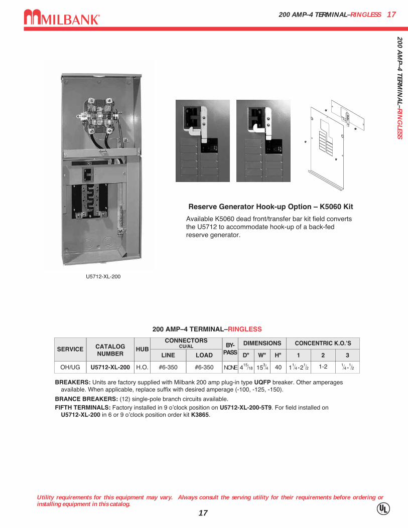
BREAKERS: Units are factory supplied with Milbank 200 amp plug-in type UQFP breaker. Other amperages available. When applicable, replace suffix with desired amperage (-100, -125, -150).
BRANCE BREAKERS: (12) single-pole branch circuits available.FIFTH TERMINALS: Factory installed in 9 oʼclock position on U5712-XL-200-5T9. For field installed on
U5712-XL-200 in 6 or 9 oʼclock position order kit K3865.
CONNECTORSCU/AL
LINE LOAD
#6-350 #6-350
SERVICE CATALOGNUMBER
HUBBY-
PASS
DIMENSIONS
D" W" H"
OH/UG U5712-XL-200 H.O. NONE 415⁄18 153⁄4 40
CONCENTRIC K.O.ʼS
1 2 3
11⁄4 -21⁄2 1-2 1⁄4 -1⁄2
200 AMP–4 TERMINAL–RINGLESS
U5712-XL-200
Reserve Generator Hook-up Option – K5060 Kit
Available K5060 dead front/transfer bar kit field convertsthe U5712 to accommodate hook-up of a back-fedreserve generator.
320 AMP–SIDE WIREWAY–METER MAIN WITH (2) 200 AMP BREAKERS–LEVER BYPASS1832
0 A
MP–
SID
E W
IREW
AY
–MET
ER M
AIN
WIT
H (
2) 2
00 A
MP
BR
EAK
ERS–
LEV
ER B
YPA
SS
Utility requirements for this equipment may vary. Always consult the serving utility for their requirements before ordering orinstalling equipment in this catalog.
18
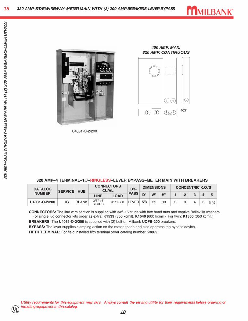
400 AMP. MAX.320 AMP. CONTINUOUS
1
3
2
5
1
4 4
2
34031
CATALOGNUMBER
U4031-O-2/200
SERVICE
UG
HUB
BLANK
CONNECTORSCU/AL
LINE LOAD3/8"-16STUDS #1/0-300
BY-PASS
LEVER
DIMENSIONS CONCENTRIC K.O.ʼS
1D" W" H"
353⁄4 25 30
2
3
3
4
4 5
3 1⁄4,1⁄2
320 AMP–4 TERMINAL–1∅–RINGLESS–LEVER BYPASS–METER MAIN WITH BREAKERS
CONNECTORS: The line wire section is supplied with 3/8"-16 studs with hex head nuts and captive Belleville washers.For single lug connector kits order as extra: K1539 (350 kcmil), K1540 (600 kcmil.) For twin: K1350 (350 kcmil.)
BREAKERS: The U4031-O-2/200 is supplied with (2) bolt-on Milbank UQFB-200 breakers. BYPASS: The lever supplies clamping action on the meter spade and also operates the bypass device.FIFTH TERMINAL: For field installed fifth terminal order catalog number K3865.
U4031-O-2/200
19320 AMP–SIDE WIREWAY–METER MAIN WITH (2) 200 AMP BREAKERS–LEVER BYPASS
Utility requirements for this equipment may vary. Always consult the serving utility for their requirements before ordering orinstalling equipment in this catalog.
19
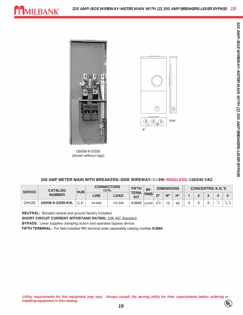
U5059-X-2/200(shown without lugs)
5059
NEUTRAL: Bonded neutral and ground factory Installed.SHORT CIRCUIT CURRENT WITHSTAND RATING: 22K AIC Standard. BYPASS: Lever supplies clamping action and operates bypass device.FIFTH TERMINAL: For field installed fifth terminal order separately catalog number K3865.
SERVICE CATALOGNUMBER
HUBCONNECTORS
CU/AL
LINE LOAD
BY-PASS
FIFTHTERM.
KIT
DIMENSIONS CONCENTRIC K.O.ʼS
1 2 3 4 5D" W" H"
OH/UG C.P. LEVER 3 3 3 1⁄4 1⁄4,1⁄247⁄8 15 42#4-600 1/0-300 K3866U5059-X-2/200-K3L
320 AMP METER MAIN WITH BREAKERS–SIDE WIREWAY–1∅3W–RINGLESS–120/240 VAC
320 AM
P–SIDE W
IREW
AY
–METER
MA
IN W
ITH (2) 200 A
MP B
REA
KER
S–LEVER
BY
PASS

200 AMP–7 TERMINAL–METER MAIN–RINGLESS2020
0 A
MP–
7 TE
RM
INA
L–M
ETER
MA
IN–R
ING
LESS
Utility requirements for this equipment may vary. Always consult the serving utility for their requirements before ordering orinstalling equipment in this catalog.
20
CATALOGNUMBER
U5750-RXL-200-BL
HUB
C.P.
CONNECTOR CU/AL BY-
PASS
LEVER
DIMENSIONS CONCENTRIC K.O.ʼS
1
11⁄4-3 3-4 1⁄2-2
2 3D"
53⁄4
W"
173⁄8
H"
34
LINE
#6-350
LOAD
C/B
AMPS
200
7 TERMINAL–METER MAIN–RINGLESS–3∅4W
U5750-RXL-200-BL
2
1
1
1
3
5750
HUBS: For proper hub selection see the hub suffix chart on the accessory page.BYPASS: The lever supplies clamping action on the meter spade and also operates the bypass
device.BREAKER: Factory installed 200 amp, 3-pole, 10,000 AIC

21200 A
MP–4 &
5 TERM
INA
L–300 VA
C–M
ETER M
AIN
RIN
GLESS–JA
W C
LAM
PING
LEVER
–AU
XILIA
RY
POW
ER C
ENTER
200 AMP–4 & 5 TERMINAL–300 VAC–METER MAINRINGLESS–JAW CLAMPING LEVER–AUXILIARY POWER CENTER
Utility requirements for this equipment may vary. Always consult the serving utility for their requirements before ordering orinstalling equipment in this catalog.
21
1 2
4
1
3 45 6
4834
U4834-XL-200-5T9(Shown with optional
200 Amp Auxiliary breaker)
CATALOGNUMBER HUB
CONNECTOR CU/AL BY-
PASS
DIMENSIONS CONCENTRIC K.O.ʼS
1 2 3 4 5D" W" H"LINE LOADAMPS SERVICE
U4834-XL-200-5T9 C.P. LEVER 3 3 3 3 1⁄4,1⁄251⁄2 17 39#6-350 (3) #6-350200 OH/UG
200 AMP–4 & 5 TERMINAL (AT 9 OʼCLOCK)–METER MAINMANUAL TRANSFER SWITCH–RINGLESS–1∅3W–120/240 VAC
AUXILIARY BREAKERS: Must be ordered separately. Use UQFP-(AMP) style breaker.FIFTH TERMINALS: For field installed fifth terminals, order catalog number K4935. Units with -5T9 suffix have fifth terminals
factory installed in 9 oʼclock position.
20 AMP–13 TERMINAL–CURRENT TRANSFORMER RATED–RINGLESS / RING TYPE2220
AM
P–13
TER
MIN
AL–
CU
RR
ENT
TRA
NSF
OR
MER
RA
TED
–RIN
GLE
SS/
RIN
G T
YPE
Utility requirements for this equipment may vary. Always consult the serving utility for their requirements before ordering orinstalling equipment in this catalog.
22
1
4 35
2
4
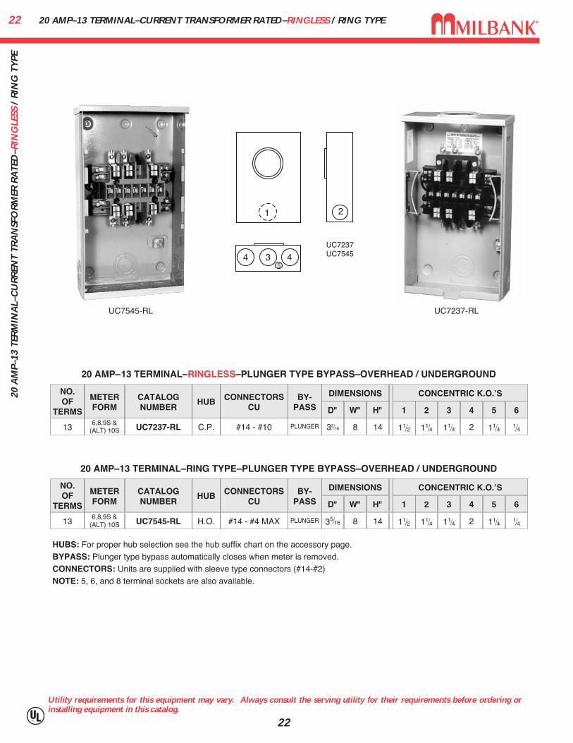
20 AMP–13 TERMINAL–RINGLESS–PLUNGER TYPE BYPASS–OVERHEAD / UNDERGROUND
NO.OF
TERMS
METERFORM
CATALOGNUMBER
HUB CONNECTORSCU
BY-PASS
DIMENSIONS CONCENTRIC K.O.ʼS
1 2 3 4 5 6D" W" H"
136,8,9S &
(ALT) 10S UC7237-RL C.P. #14 - #10 PLUNGER 11⁄2 11⁄4 11⁄4 2 11⁄4 1⁄435⁄16 8 14
20 AMP–13 TERMINAL–RING TYPE–PLUNGER TYPE BYPASS–OVERHEAD / UNDERGROUND
UC7545-RL UC7237-RL
NO.OF
TERMS
METERFORM
CATALOGNUMBER
HUB CONNECTORSCU
BY-PASS
DIMENSIONS CONCENTRIC K.O.ʼS
1 2 3 4 5 6D" W" H"
136,8,9S &
(ALT) 10S UC7545-RL H.O. #14 - #4 MAX PLUNGER 11⁄2 11⁄4 11⁄4 2 11⁄4 1⁄435⁄16 8 14
HUBS: For proper hub selection see the hub suffix chart on the accessory page.BYPASS: Plunger type bypass automatically closes when meter is removed.CONNECTORS: Units are supplied with sleeve type connectors (#14-#2)NOTE: 5, 6, and 8 terminal sockets are also available.
UC7237UC7545
2320 A
MP–13 TER
MIN
AL–TR
AN
SFOR
MER
RA
TED–R
ING
LESS–600 VA
C20 AMP–13 TERMINAL–TRANSFORMER RATED–RINGLESS–600 VAC
Utility requirements for this equipment may vary. Always consult the serving utility for their requirements before ordering orinstalling equipment in this catalog.
23
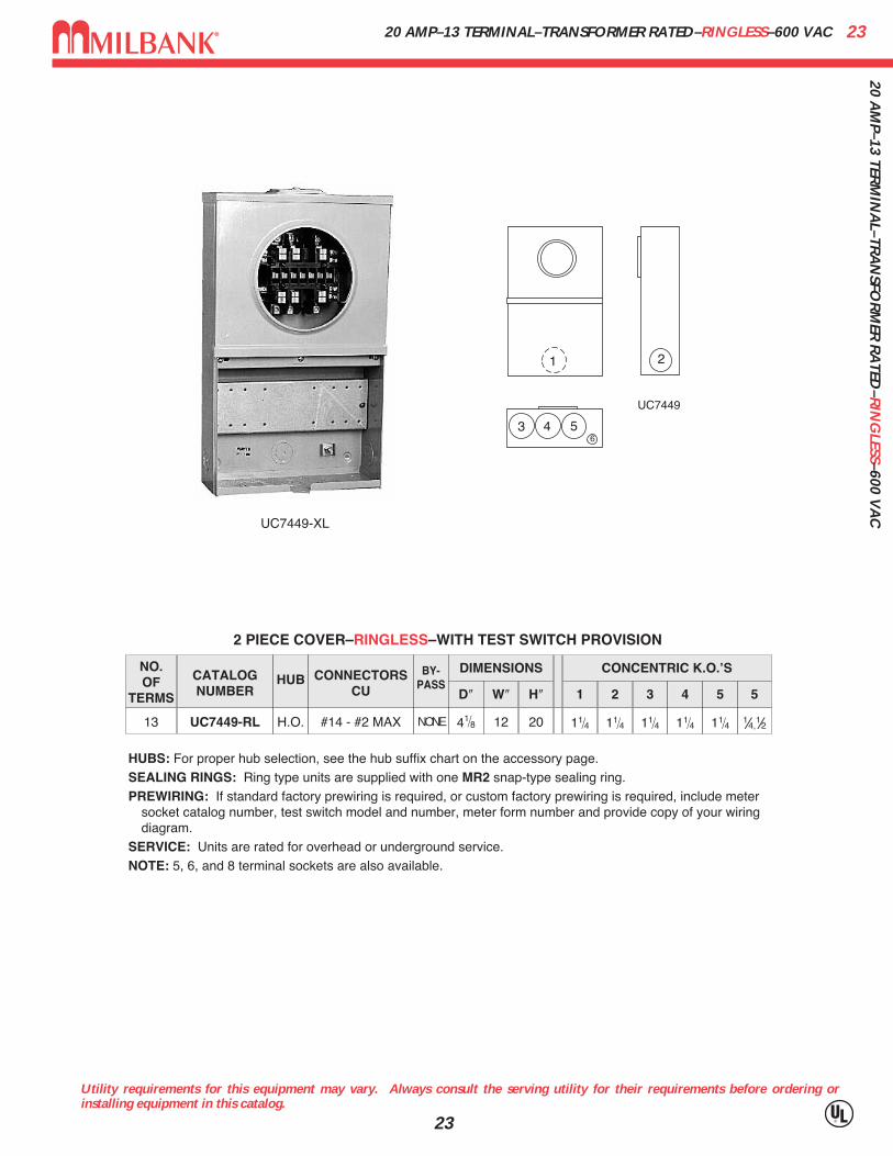
UC7449-XL
1
3 4 56
2
CATALOGNUMBER
HUB CONNECTORSCU
BY-PASS
DIMENSIONS CONCENTRIC K.O.ʼS
1 2 3 4 5 5D″ W″ H″
UC7449-RL H.O. NONE 11⁄4 11⁄4 11⁄4 11⁄4 11⁄4 1⁄4,1⁄241⁄8 12 20#14 - #2 MAX
NO.OF
TERMS
13
2 PIECE COVER–RINGLESS–WITH TEST SWITCH PROVISION
HUBS: For proper hub selection, see the hub suffix chart on the accessory page.SEALING RINGS: Ring type units are supplied with one MR2 snap-type sealing ring.PREWIRING: If standard factory prewiring is required, or custom factory prewiring is required, include meter
socket catalog number, test switch model and number, meter form number and provide copy of your wiring diagram.
SERVICE: Units are rated for overhead or underground service.NOTE: 5, 6, and 8 terminal sockets are also available.
UC7449

20 & 80 AMP–TRANSFORMER RATEDJAW CLAMPING LEVER BYPASS–RINGLESS–600 VAC24
20 &
80
AM
P–TR
AN
SFO
RM
ER R
ATE
DJA
W C
LAM
PIN
G L
EVER
BY
PASS
–RIN
GLE
SS–6
00 V
AC
Utility requirements for this equipment may vary. Always consult the serving utility for their requirements before ordering orinstalling equipment in this catalog.
24
U4493-XL
1 23
4 556
80 AMP TRANSFORMER RATED—LEVER BYPASS—RINGLESS
NO.OF
TERMSSERVICE CATALOG
NUMBERHUB CONNECTORS
CUBY-
PASS
DIMENSIONS CONCENTRIC K.O.ʼS
1 2 3 4 5 6D″ W″ H″
13 OH/UG U4493-XL C.P. #14 - #4 MAX LEVER 3 11⁄2 3⁄4 3⁄4 11⁄2 1⁄447⁄8 10 181⁄2
BYPASS: Lever operates current bypass device and also supplies clamping action on current meter spades.TEST SWITCH COVERS: Units on this page can be used with clear lexan cover. See accessory page for ordering information.CONNECTORS: Units are supplied with mechanical type connectors (#4 max.) If compression type connectors (#10) are
preferred, change catalog prefix to “S” (i.e. U4493-XL becomes S4493-XL.) The “S” also designates non-U/L.REMOVABLE HANDLE: When removable handle is desired add suffix “-RH” to catalog number (i.e. U4493-XL becomes
U4493-XL-RH.)REPLACEMENT REMOVABLE HANDLE: When a replacement removable handle (RH) is required order part #Z706850-SC.
Replacement handle will only work with factory ordered RH units.BLOCK ASSEMBLY: Block assembly rated at 80 amps-test switch rated at 20 amps—therefore, unit defaults to test
switch rating of 20 amps.NOTE: 6 and 8 terminal sockets are also available.
4993
25400 A
MP–6, 8 &
13 TERM
INA
L–TRA
NSO
CK
ET FOR
USE W
ITH B
AR
TYPE C
.T.’S400 AMP–6, 8 & 13 TERMINAL–TRANSOCKET FOR USE WITH BAR TYPE C.T.’S
Utility requirements for this equipment may vary. Always consult the serving utility for their requirements before ordering orinstalling equipment in this catalog.
25
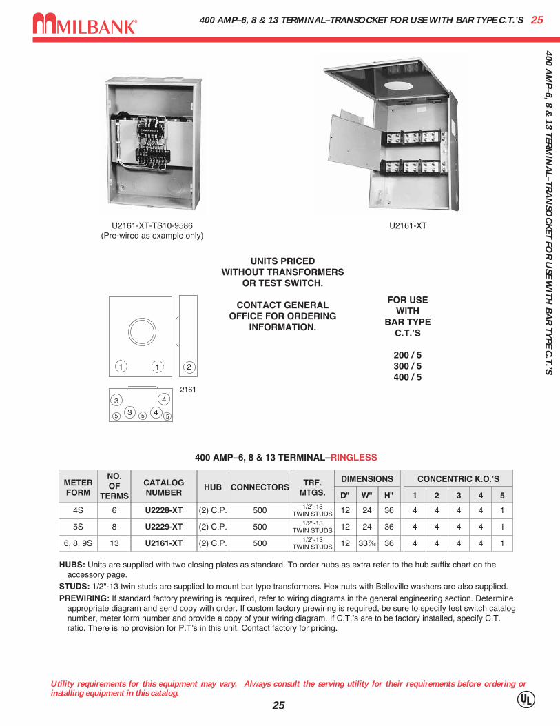
U2161-XT-TS10-9586(Pre-wired as example only)
U2161-XT
400 AMP–6, 8 & 13 TERMINAL–RINGLESS
NO.OF
TERMS
METERFORM
CATALOGNUMBER
HUB CONNECTORS TRF.MTGS.
DIMENSIONS CONCENTRIC K.O.ʼS
1 2 3 4 5D" W" H"
64S U2228-XT (2) C.P. 500 1/2"-13TWIN STUDS 4 4 4 4 112 24 36
85S U2229-XT (2) C.P. 500 1/2"-13TWIN STUDS 4 4 4 4 112 24 36
136, 8, 9S U2161-XT (2) C.P. 500 1/2"-13TWIN STUDS 4 4 4 4 112 33 7⁄16 36
HUBS: Units are supplied with two closing plates as standard. To order hubs as extra refer to the hub suffix chart on the accessory page.
STUDS: 1/2"-13 twin studs are supplied to mount bar type transformers. Hex nuts with Belleville washers are also supplied.PREWIRING: If standard factory prewiring is required, refer to wiring diagrams in the general engineering section. Determine
appropriate diagram and send copy with order. If custom factory prewiring is required, be sure to specify test switch catalognumber, meter form number and provide a copy of your wiring diagram. If C.T.ʼs are to be factory installed, specify C.T.ratio. There is no provision for P.Tʼs in this unit. Contact factory for pricing.
UNITS PRICEDWITHOUT TRANSFORMERS
OR TEST SWITCH.
CONTACT GENERALOFFICE FOR ORDERING
INFORMATION.
FOR USE WITH
BAR TYPE C.T.ʼS
200 / 5300 / 5400 / 5
211
5 5 5
3
3 4
42161
C.T.ʼSQTY.
& RATIO
(2) 200/5
(3) 200/5
(3) 200/5
600 AMP–6, 8, 13 & 14 TERMINAL–COMMERCIAL TRANSOCKETP.T.’S, DONUT OR BAR TYPE C.T.’S–600 VAC26
600
AM
P–6,
8, 1
3 &
14
TER
MIN
AL–
CO
MM
ERC
IAL
TRA
NSO
CK
ETP.
T.’S
, DO
NU
T O
R B
AR
TY
PE C
.T.’S
–600
VA
C
Utility requirements for this equipment may vary. Always consult the serving utility for their requirements before ordering orinstalling equipment in this catalog.
26
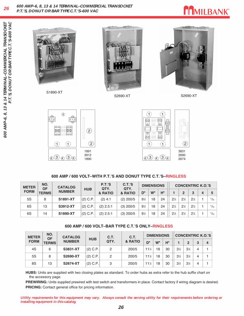
S1890-XTS2690-XT S2690-XT
600 AMP / 600 VOLT–WITH P.T.ʼS AND DONUT TYPE C.T.ʼS–RINGLESS
NO.OF
TERMS
METERFORM
CATALOGNUMBER
HUBP.T.ʼSQTY.
& RATIO
DIMENSIONS CONCENTRIC K.O.ʼS
1 2 3 4 5D" W" H"
85S S1891-XT (2) C.P. (2) 4:1 21⁄2 21⁄2 21⁄2 1 11⁄1691⁄2 18 24
136S S3912-XT (2) C.P. (2) 2.5:1 21⁄2 21⁄2 21⁄2 1 11⁄1691⁄2 18 24
146S S1890-XT (2) C.P. (2) 2.5:1 21⁄2 21⁄2 21⁄2 1 11⁄1691⁄2 18 24
C.T.& RATIO
200/5
200/5
200/5
600 AMP / 600 VOLT–BAR TYPE C.T.ʼS ONLY–RINGLESS
NO.OF
TERMS
METERFORM
CATALOGNUMBER
HUB C.T.QTY.
DIMENSIONS CONCENTRIC K.O.ʼS
1 2 3 4D" W" H"
64S S3831-XT (2) C.P. 2 31⁄2 31⁄2 4 1111⁄4 18 30
85S S2690-XT (2) C.P. 2 31⁄2 31⁄2 4 1111⁄4 18 30
138S S2674-XT (2) C.P. 3 31⁄2 31⁄2 4 1111⁄4 18 30
HUBS: Units are supplied with two closing plates as standard. To order hubs as extra refer to the hub suffix chart on the accessory page.
PREWIRING: Units supplied prewired with test switch and transformers in place. Contact factory if wiring diagram is desired.PRICING: Contact general office for pricing information.
11 2
3 34 44
5
2
2
34 44
1 1
1 1
3
189139121890
383126902674
271200-1600 A
MP–M
AX
I-TRA
NSO
CK
ET WITH
P.T.’S AN
D B
AR
TYPE C
.T.’S–480 VA
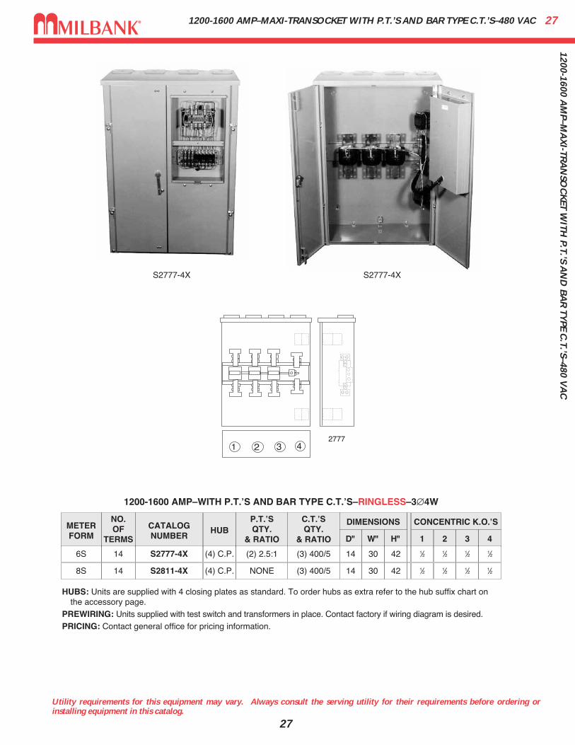
C1200-1600 AMP–MAXI-TRANSOCKET WITH P.T.’S AND BAR TYPE C.T.’S–480 VAC
Utility requirements for this equipment may vary. Always consult the serving utility for their requirements before ordering orinstalling equipment in this catalog.
27
S2777-4X S2777-4X
C.T.ʼSQTY.
& RATIO
(3) 400/5
(3) 400/5
1200-1600 AMP–WITH P.T.ʼS AND BAR TYPE C.T.ʼS–RINGLESS–3∅4W
NO.OF
TERMS
METERFORM
CATALOGNUMBER
HUBP.T.ʼSQTY.
& RATIO
DIMENSIONS CONCENTRIC K.O.ʼS
1 2 3 4D" W" H"
146S S2777-4X (4) C.P. (2) 2.5:1 1⁄2 1⁄2 1⁄2 1⁄214 30 42
148S S2811-4X (4) C.P. NONE 1⁄2 1⁄2 1⁄2 1⁄214 30 42
HUBS: Units are supplied with 4 closing plates as standard. To order hubs as extra refer to the hub suffix chart on the accessory page.
PREWIRING: Units supplied with test switch and transformers in place. Contact factory if wiring diagram is desired.PRICING: Contact general office for pricing information.
1 2 3 42777
100 / 200 AMP–1∅–120 / 240 VAC–4 TERMINAL–METER MAIN PEDESTAL2810
0 /
200
AM
P–1∅
–120
/ 2
40 V
AC
–4 T
ERM
INA
L–M
ETER
MA
IN P
EDES
TAL
Utility requirements for this equipment may vary. Always consult the serving utility for their requirements before ordering orinstalling equipment in this catalog.
28
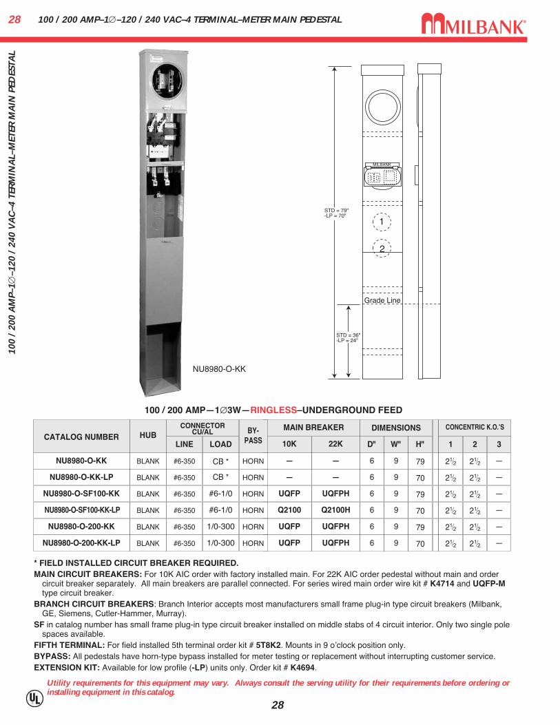
100 / 200 AMP—1∅3W—RINGLESS–UNDERGROUND FEED
HUBCONNECTOR
CU/AL
LINE LOAD
BLANK #6-350 CB *
CATALOG NUMBER
NU8980-O-KK
NU8980-O-KK-LP BLANK #6-350 CB *
BLANK #6-350 #6-1/0NU8980-O-SF100-KK
NU8980-O-SF100-KK-LP
NU8980-O-200-KK
NU8980-O-200-KK-LP
22K10K
MAIN BREAKER
——
— —
UQFPHUQFP
Q2100HQ2100
UQFPHUQFP
UQFPHUQFP
BLANK
BLANK
BLANK
DIMENSIONS CONCENTRIC K.O.ʼS
1 2 3D" W" H"
21⁄2 21⁄2 —6 9 79
21⁄2 21⁄2 —6 9 70
21⁄2 21⁄2 —6 9 79
21⁄2
21⁄2
21⁄2
21⁄2
21⁄2
21⁄2
—
—
—
6
6
6
9
9
9
70
79
70
#6-350
#6-350
#6-350
#6-1/0
1/0-300
1/0-300
MILBANK
1
2
Grade Line
STD = 79"-LP = 70"
STD = 36"-LP = 24"
* FIELD INSTALLED CIRCUIT BREAKER REQUIRED.MAIN CIRCUIT BREAKERS: For 10K AIC order with factory installed main. For 22K AIC order pedestal without main and order
circuit breaker separately. All main breakers are parallel connected. For series wired main order wire kit # K4714 and UQFP-Mtype circuit breaker.
BRANCH CIRCUIT BREAKERS: Branch Interior accepts most manufacturers small frame plug-in type circuit breakers (Milbank,GE, Siemens, Cutler-Hammer, Murray).
SF in catalog number has small frame plug-in type circuit breaker installed on middle stabs of 4 circuit interior. Only two single polespaces available.
FIFTH TERMINAL: For field installed 5th terminal order kit # 5T8K2. Mounts in 9 oʼclock position only.BYPASS: All pedestals have horn-type bypass installed for meter testing or replacement without interrupting customer service.EXTENSION KIT: Available for low profile (-LP) units only. Order kit # K4694.
NU8980-O-KK
BY-PASS
HORN
HORN
HORN
HORN
HORN
HORN

29320 A
MP–4 TER
MIN
AL–M
ETER PED
ESTAL W
ITH LEV
ER B
YPA
SS320 AMP–4 TERMINAL–METER PEDESTAL WITH LEVER BYPASS
Utility requirements for this equipment may vary. Always consult the serving utility for their requirements before ordering orinstalling equipment in this catalog.
29
CATALOGNUMBER
U3849-O-2/200
SERVICE
UG
HUB
NONE
CONNECTORSCU/AL
LINE LOAD3/8" X 16STUDS
C.B. #1- 300kcmil
BY-PASS
LEVER
DIMENSIONS CONCENTRIC K.O.ʼS
1D" W" H"
21⁄247⁄8 13 58
2
21⁄2
3
5⁄16
4
—
5
—
320 AMP–4 TERMINAL—METER MAIN WITH BREAKERS—RINGLESS—240 VAC
CATALOGNUMBER
U1748-O
SERVICE
UG
HUB
NONE
CONNECTORSCU/AL
LINE LOAD3/8" X 16STUDS
TWIN#6-350 kcmil
BY-PASS
LEVER
DIMENSIONS CONCENTRIC K.O.ʼS
1D" W" H"
21⁄247⁄8 13 64
2
21⁄2
3
21⁄2
4
5⁄16
5
—
320 AMP–4 TERMINAL—WITHOUT BREAKER—RINGLESS—600 VAC
CONNECTORS: The line wire section is supplied with 3⁄8"–16 studs with hex head nuts and captive Belleville washers. The line side connectors are to be supplied by the Utility, load side is furnished.
BYPASS: The lever supplies clamping action on the meter spade and also operates the bypass device.FIFTH TERMINAL: For field installed fifth terminal order kit #K3865.PEDESTAL EXTENSION KIT: If extension kit is required, order as extra kit # S1848.
BREAKERS: The U3849 is furnished with (2) 200 amp Milbank type UQFBH-200 circuit breakers.PEDESTAL EXTENSION KIT: If extension kit is required, order as extra kit # S1848.THIS UNIT IS RATED 22,000 AIC—SHORT CIRCUIT CURRENT RATING WITH MILBANK UQFBH SERIES CIRCUIT
BREAKER.
U3849-O-2/200U1748-O
Grade Line
1 2
3
M I L B A N K
3
3 3
Grade Line
18"
Grade Line
1
2 3
1
2
4 4
4 4
Grade Line
18"
320 AMP CONTINUOUS400 AMP MAX
4-27/32"�I.D.13" �
O.D.
16-15/16"15"
S1848Pedestal Extension Unit

480 AMP CONTINUOUS–4 TERMINAL–K-SERIES METER MAIN3048
0 A
MP
CO
NTI
NU
OU
S–4
TER
MIN
AL–
K-S
ERIE
S M
ETER
MA
IN
Utility requirements for this equipment may vary. Always consult the serving utility for their requirements before ordering orinstalling equipment in this catalog.
30
SPECIFICATIONS
� Service Type: OH/UG (top closing plate included)
� Application: 1∅, 3W Self-Contained Type MS-K Watt-Hour Meters
� By-pass Device: Rated 50% – Manual Type (Order Separately No. K4687)
� Cover Style: Sealable Ringless Meter Cover (both in-service and out-or-service positions)
� Line-Sided Connectors: Twin 350 kcmil Connectors Included
� Load-Side Connectors: Double 300 kcmil Connectors Included on Breakers
� Dimensions: 45"H X 24"W X 6"D
� Weight: 96 lbs.
� UL Listed
CATALOG NUMBER BREAKERS
U5067-X-2/200 Twin 200-Amp Breakers
U5067-X-2/225 Twin 225-Amp Breakers
� Rated for Overhead or Underground Service(Top Closing Plate Provided)
� 4 Terminal, 480 Amp Continuous, 1∅3W
� Suitable for Service Entrance
� Two Main Circuit Breakers –225 Amp or 200 Amp(Twin Mains Allow Unit to Feed Multiple Panels)

31100 / 200 AMP–4 TERMINAL–RESIDENTIAL PEDESTALSINGLE OR DOUBLE POSITION–1∅3W–600 VAC
Utility requirements for this equipment may vary. Always consult the serving utility for their requirements before ordering orinstalling equipment in this catalog.
31
Extension UnitK5800
U8436-O
HANGING HOOK: Supplied with keyhole hanger for easy mounting.EXTENSION UNIT: For 24" burial applications, order extension unit S8988 for U8303-O. For 15" burial applications, order exten-
sion unit K5800 for U8436; for 30" applications, order (2) K5800 units.FIFTH TERMINAL: For field installed fifth terminal on U8436, order catalog number K5T (9 oʼclock position). For field installed
fifth terminal on U8303-O, order catalog number 5T8K2 (9 oʼclock position).BYPASS: Horn type bypass used on both units.
AMP
200
SERVICE CATALOGNUMBER
HUB
UG U8436-O BLANK
CONNECTORSCU/AL
LINE(COMPRESSION) LOAD
BY-PASS
HORN
DIMENSIONS CONCENTRIC K.O.ʼS
1 2 3 4 5
2 2 5⁄161⁄2 2
D" W" H"
41⁄8 9 624/0 (Line)2/0 (Neutral) #6-350
6
—
200 2 POS-UG U8303-O BLANK HORN 11⁄4 5⁄16 21⁄2 21⁄2 21⁄241⁄2 83⁄16 744/0 (Line)2/0 (Neutral) #6-350 1⁄4,
1⁄2
100 / 200 AMP—4 TERMINAL—RINGLESS—1∅3W—600 VAC
18"
Grade Line
3
Grade Line
CHECHAMILBANK
6
6
221
CHECHA
52
3
24 4
U8303-O
Extension UnitS8988
GRADE LINE
1
2
2
5
32
3
4
18.00
100 / 200 AM
P–4 TERM
INA
L–RESID
ENTIA
L PEDESTA
LSIN
GLE O
R D
OU
BLE PO
SITION
–1∅3W
–600 VA
C

200 AMP–RINGLESS–METERED PEDESTALS3220
0 A
MP–
RIN
GLE
SS–M
ETER
ED P
EDES
TALS
32
SPECIFICATIONS• UL listed – conforms to EUSERC drawing number 307• 200 amp maximum, 120/240 volt, single phase, three wire meter socket• Ringless meter socket with horn bypass and stainless steel latch• Short circuit withstand rating 22K AIC.• Type 3R construction for durable outdoor use, one piece post – lockable and sealable• Milbank grey polyester powder coat finish• Wire terminations accept copper or aluminum conductors• Line & Neutral: (2) #6-350 kcmil per phase• Line Ground: (4) #14-1/0• Load (CB): 2/0 to 300 kcmil per pole• Load Neutral: (1) #6-350 kcmil• Load Ground: (2) #14-1/0, (4) #14/6• Milbank plug-in main circuit breaker. Available in 100, 125, 150 & 200 amp. Type UQFPH-M.• Four-circuit plated copper interior accepts (2) 2-pole or (4) 1-pole standard plug-in type circuit breakers up to a
total of 125 amps maximum. Acceptable manufacturers: Cutler-Hammer, GE or Siemens• Factory or field installable receptacle bridge and receptacle / circuit breaker kits available. See Accessories.
U5136-0-200S with series wiredmain & K5400-520GR kit
33200 A
MP–R
ING
LESS–METER
ED PED
ESTALS
200 AMP–RINGLESS–METERED PEDESTALS
Utility requirements for this equipment may vary. Always consult the serving utility for their requirements before ordering orinstalling equipment in this catalog.
33
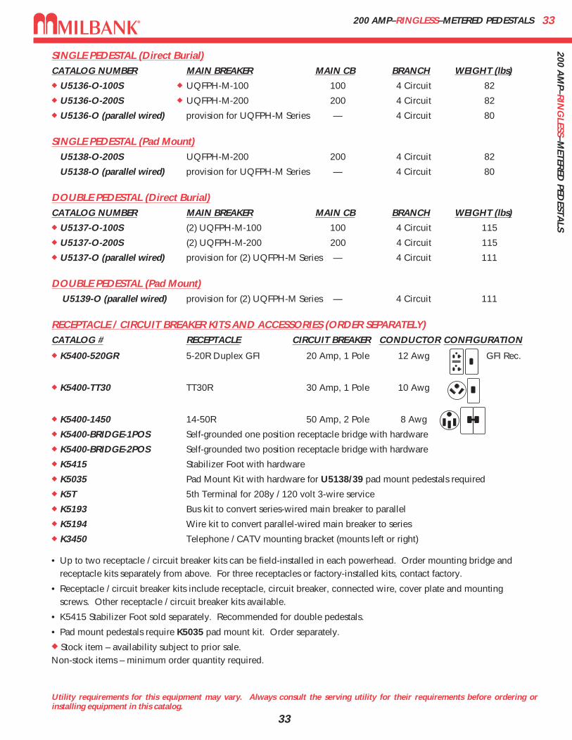
SINGLE PEDESTAL (Direct Burial)CATALOG NUMBER MAIN BREAKER MAIN CB BRANCH WEIGHT (lbs)� U5136-O-100S � UQFPH-M-100 100 4 Circuit 82
� U5136-O-200S � UQFPH-M-200 200 4 Circuit 82
� U5136-O (parallel wired) provision for UQFPH-M Series — 4 Circuit 80
SINGLE PEDESTAL (Pad Mount)U5138-O-200S UQFPH-M-200 200 4 Circuit 82
U5138-O (parallel wired) provision for UQFPH-M Series — 4 Circuit 80
DOUBLE PEDESTAL (Direct Burial)CATALOG NUMBER MAIN BREAKER MAIN CB BRANCH WEIGHT (lbs)� U5137-O-100S (2) UQFPH-M-100 100 4 Circuit 115
� U5137-O-200S (2) UQFPH-M-200 200 4 Circuit 115
� U5137-O (parallel wired) provision for (2) UQFPH-M Series — 4 Circuit 111
DOUBLE PEDESTAL (Pad Mount)U5139-O (parallel wired) provision for (2) UQFPH-M Series — 4 Circuit 111
RECEPTACLE / CIRCUIT BREAKER KITS AND ACCESSORIES (ORDER SEPARATELY)CATALOG # RECEPTACLE CIRCUIT BREAKER CONDUCTOR CONFIGURATION
� K5400-520GR 5-20R Duplex GFI 20 Amp, 1 Pole 12 Awg GFI Rec.
� K5400-TT30 TT30R 30 Amp, 1 Pole 10 Awg
� K5400-1450 14-50R 50 Amp, 2 Pole 8 Awg
� K5400-BRIDGE-1POS Self-grounded one position receptacle bridge with hardware
� K5400-BRIDGE-2POS Self-grounded two position receptacle bridge with hardware
� K5415 Stabilizer Foot with hardware
� K5035 Pad Mount Kit with hardware for U5138/39 pad mount pedestals required
� K5T 5th Terminal for 208y / 120 volt 3-wire service
� K5193 Bus kit to convert series-wired main breaker to parallel
� K5194 Wire kit to convert parallel-wired main breaker to series
� K3450 Telephone / CATV mounting bracket (mounts left or right)
• Up to two receptacle / circuit breaker kits can be field-installed in each powerhead. Order mounting bridge andreceptacle kits separately from above. For three receptacles or factory-installed kits, contact factory.
• Receptacle / circuit breaker kits include receptacle, circuit breaker, connected wire, cover plate and mountingscrews. Other receptacle / circuit breaker kits available.
• K5415 Stabilizer Foot sold separately. Recommended for double pedestals.
• Pad mount pedestals require K5035 pad mount kit. Order separately.
� Stock item – availability subject to prior sale.Non-stock items – minimum order quantity required.

U5706 & U5707 TEMP TO FINAL SERVICE PEDESTAL–RINGLESS / RING TYPE34U
5706
& U
5707
TEM
P TO
FIN
AL
SER
VIC
E PE
DES
TAL–
RIN
GLE
SS /
RIN
G T
YPE
Utility requirements for this equipment may vary. Always consult the serving utility for their requirements before ordering orinstalling equipment in this catalog.
34
SPECIFICATIONS• 200 amp, 1∅, 120/240 volt, 22K AIC, underground service only.• U5706 has Ringless meter socket available with or without horn bypass (-KK). • U5707 has Ring type meter socket with MR-4 screw type meter ring.• Suitable for use as service equipment, mobile home service equipment and temporary power
service equipment.*• Provisions for up to two Type 3R in-use receptacle kits. *• Order receptacle and bridge kits separately. See ordering information.• Direct burial pedestal suitable for free standing or structure mounted installation.• Separate line and load wireways are removable, lockable and sealable for security.• Left side is for utility connection. Right side is for customer underground load exit.• Convenient knockouts in post for thru-wall load exit requirements.• Type 3R enclosure constructed with type G90 galvanized steel. • Repaintable light gray polyester powder coat finish.• Wire terminations accept copper or aluminum conductors: Line & Neutral: #6-350 Ground: (4) #14-1/0.• Main circuit breaker can be series or parallel connected. • Universal 4 circuit branch 125 amp interior (up to (2) 2-pole) accepts most manufacturers plug-in type
circuit breakers. See wiring diagram.
U5706-O-200S*(Shown with (2) K5400-520GR receptacles,
K5400-BRIDGE-2POS & line side conduc-tor installed.)
8-1/2”
13-1/4”
19”
A
A
A
A
A
30-3/16”
E
Bridge Kit(4) .173” Extr. Holes
3-1/2”
B
C
D
OPEN
Concentric KnockoutsA (4) = 1, 1-1/2, 2, 2-1/2”
B (1) = 1-1/4, 1-1/2, 2”
C (1) = 3/4”, 1”
D (1) = 1/4”, 1/2”
E (1) = 1” Solid

35U5706 & U5707 TEMP TO FINAL SERVICE PEDESTAL–RINGLESS / RING TYPE
Utility requirements for this equipment may vary. Always consult the serving utility for their requirements before ordering orinstalling equipment in this catalog.
35
U5706 Ringless PedestalMain Main Replacement Branch Weight
Catalog Number Amps Service By-Pass Circuit Breaker Wired Main Type* Circuits LBS.
� U5706-O-200S 200 120/240 None 200a 2p Series UQFPH-M 4 79
� U5706-O-200S-KK 200 120/240 Horn 200a 2p Series UQFPH-M 4 79
Up to two receptacle/circuit breaker kits can be field or factory installed. See below for ordering information. Contact factory for factory installed kits.
To increase pedestal height, order field-installed post extension kit K5708.For field installed fifth terminal in the 9 oʼclock position, order kit 5T9.For field converting from parallel to series wired, order kit K5194. For field converting from series to parallel wired, order kit K5193.
Receptacle / Circuit Breaker Kits & Receptacle Bridge Kits
Catalog Number Amps/ Volts NEMA Config Circuit Breaker Conductor Configuration
� K5400-520GR 20a 120v 5-20R Duplex GFI 20a 1p 12 awg Fig. 1
� K5400-620 20a 240v 6-20R Simplex 20a 2p 12 awg Fig. 2
� K5400-620GB 20a 240v 6-20R Simplex 20a 240v GFI 12 awg Fig. 3
� K5400-1450 50a 120/240v 14-50R 50a 120/240v 8 awg Fig. 4
� K5400-1450GB 50a 120/240v 14-50R 50a 120/240v GFI 8 awg Fig. 4
� K5400-BRIDGE-1POS Self-grounded ONE position bridge with hardware and instructions. Fig. 5
� K5400-BRIDGE-2POS Self-grounded TWO position bridge with hardware and instructions. Fig. 6
Receptacle kits include: receptacle, circuit breaker, connected wire, cover plate, mounting screws and instructions. Contact factory for other kits.
NOTE: Receptacle grounding is provided by metal contact with bridge and pedestal. Be sure to torque all fasteners per torque requirements.
� Stock item – availability subject to prior sale.
Non-stock items – minimum order quantity required.
Fig. 1 Fig. 2 Fig. 3 Fig. 4K5400-520GR K5400-620 K5400-620GB K5400-1450
Fig. 5 Fig. 6 Fig. 7K5400-BRIDGE-1POS K5400-BRIDGE-2POS UQFPH-M-200
U5706 &
U5707 TEM
P TO FIN
AL SER
VIC
E PEDESTA
L–RIN
GLESS / R
ING
TYPE

200 AMP–4 TERMINAL–MOBILE HOME METER PEDESTALS–RINGLESS–120/240 VAC3620
0 A
MP–
4 TE
RM
INA
L–M
OB
ILE
HO
ME
MET
ER P
EDES
TALS
–RIN
GLE
SS–1
20/2
40 V
AC
Utility requirements for this equipment may vary. Always consult the serving utility for their requirements before ordering orinstalling equipment in this catalog.
36
U4322-O
ST ABILIZER FOOT 12"
21"
55"
10"
5 1/2"
4 1/8"
U4322
METERPOSITIONS
BY-PASS
MOUNTINGTYPE
TWINLINE CONNECTORS
CU/AL
CIRCUITPROV.
SINGLE LEVER POST #6 AWG-350 kcmil 6
CATALOGNUMBER
U4322-O-5T9
DESCRIPTION
Provisions for Main withBranch or Parallel Breakers
LEVER BYPASS: Lever provides clamping action on meter spades and also operates bypass device.
APPLICATION: The U4322 pedestals are suitable for use as service equipment or mobile home service equipment. K5081 /K3188 for direct burial application is included with unit. K5151 for pad mount application must be ordered as extra.
BREAKERS: These units are wired as parallel mains and have provisions for six circuits: six single-pole or three double-polebreakers. Quadplex style breakers may be used in accordance to the NEC. If main breaker is used, there are provisions for two2-pole breakers or four 1-pole breakers in series.
FIFTH TERMINAL: For field installed fifth terminal order catalog number K3865 (neutral wire not provided) or K3866 (with neutralwire). Both may be installed in 6 oʼclock or 9 oʼclock position.
200 AMP—4 TERMINAL—RINGLESS
PLUG-IN BREAKER COMPATIBILITY CHART
AMPS MILBANK CUTLER-HAMMER(WESTINGHOUSE)
SIEMENS(ITE)
SIEMENSMURRAY /
CROUSE-HINDSG.E. SQ-D
125-200 Q / QN HQP / BR / WBJ QN MD Q LINE —
≤ 100 Q QUICKLAG P /BR / HQP QP MP Q LINE HOMELINE
37100, 200 &
400 AM
P–TERM
INA
L BO
X–1∅
& 3∅
–120 / 240 VO
LT–600 VA
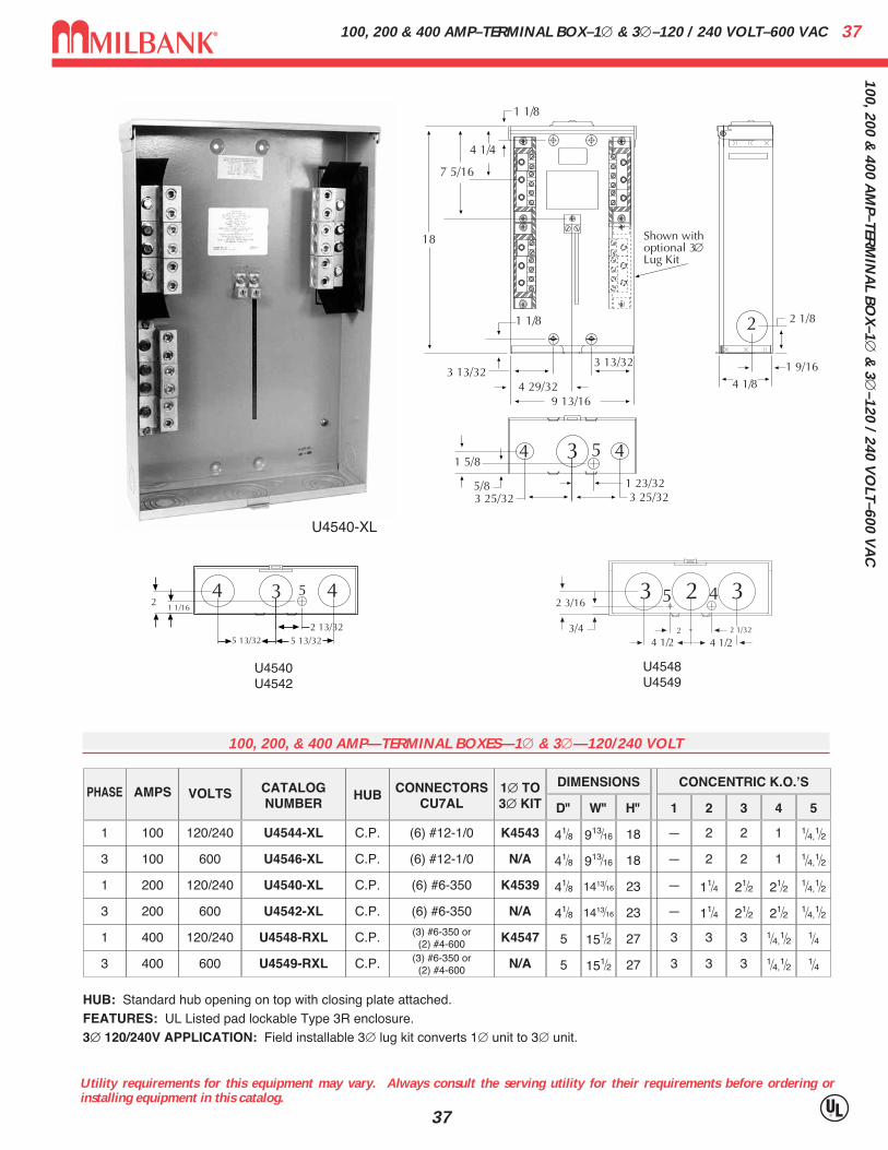
C100, 200 & 400 AMP–TERMINAL BOX–1∅ & 3∅–120 / 240 VOLT–600 VAC
Utility requirements for this equipment may vary. Always consult the serving utility for their requirements before ordering orinstalling equipment in this catalog.
37
U4540-XL
AMPSPHASE VOLTS CATALOGNUMBER
HUB CONNECTORSCU7AL
1∅ TO3∅ KIT
1001
3
120/240 U4544-XL C.P. (6) #12-1/0 K4543
DIMENSIONS CONCENTRIC K.O.ʼS
1 2 3 4 5
— 2 2 1 1⁄4,1⁄2
D" W" H"
41⁄8 913⁄16 18
100 600 U4546-XL C.P. (6) #12-1/0 N/A — 2 2 1 1⁄4,1⁄241⁄8 913⁄16 18
1 200 120/240 U4540-XL C.P. (6) #6-350 K4539 — 11⁄4 21⁄2 21⁄2 1⁄4,1⁄241⁄8 1413⁄16 23
3 200 600 U4542-XL C.P. (6) #6-350 N/A — 11⁄4 21⁄2 21⁄2 1⁄4,1⁄241⁄8 1413⁄16 23
1 400 120/240 U4548-RXL C.P. (3) #6-350 or(2) #4-600 K4547 3 3 3 1⁄4,
1⁄2 1⁄45 151⁄2 27
3 400 600 U4549-RXL C.P. (3) #6-350 or(2) #4-600 N/A 3 3 3 1⁄4,
1⁄2 1⁄45 151⁄2 27
HUB: Standard hub opening on top with closing plate attached.FEATURES: UL Listed pad lockable Type 3R enclosure.3∅ 120/240V APPLICATION: Field installable 3∅ lug kit converts 1∅ unit to 3∅ unit.
U4540U4542
U4548U4549
100, 200, & 400 AMP—TERMINAL BOXES—1∅ & 3∅—120/240 VOLT

CT3R–CURRENT TRANSFORMER CABINET / PANEL ENCLOSURE–TYPE 3R38C
T3R
–CU
RR
ENT
TRA
NSF
OR
MER
CA
BIN
ET /
PA
NEL
EN
CLO
SUR
E–TY
PE 3
R
38
PRODUCT UPC # WEIGHT CTN PANELCATALOG NO. FAMILY (7-84572) (LBS) QTY W X H X D CAT. NO.
363010-CT3R CN3R 18823 99 1 36 x 30 x 10 A-36P30
363016-CT3R CN3R 16181 121.5 1 36 x 30 x 16 A-36P30
363610-CT3R CN3R 17368 113 1 36 x 36 x 10 A-36P36
363612-CT3R CN3R 16185 118 1 36 x 36 x 12 A-36P36
363616-CT3R CN3R 18819 139 1 36 x 36 x 16 A-36P36
483616-CT3R CN3R 25707 163 1 48 x 36 x 16 A-48P36
484812-CT3R CN3R 16184 210 1 48 x 48 x 12 A-48P48
606013-CT3R CN3R 18252 274 1 60 x 60 x 13 A-60P60
Application• Designed for use as a current transformer cabinet or panel enclosure• For outdoor use to provide protection against rain, sleet, and snow, or
indoor use to protect against dripping water
Construction• Enclosure and cover manufactured from 16 or 14 gauge
G90U galvanized steel• The doors are overlapping with no center post• Continuous door hinge with stainless steel hinge pins• Three point pad-lockable handle• Panel mounting studs provided for optional back panels• Drip shield top and seam free sides, front and back
Finish• ANSI 61 gray polyester powder coating over phosphatized G90U gal-
vanized steelIndustry Standards• NEMA —Type 3R• UL 50—Type 3R• CUL—Type 3R (Equivalent to CSA)
39A
CC
ESSOR
IESACCESSORIES
Utility requirements for this equipment may vary. Always consult the serving utility for their requirements before ordering orinstalling equipment in this catalog.
39
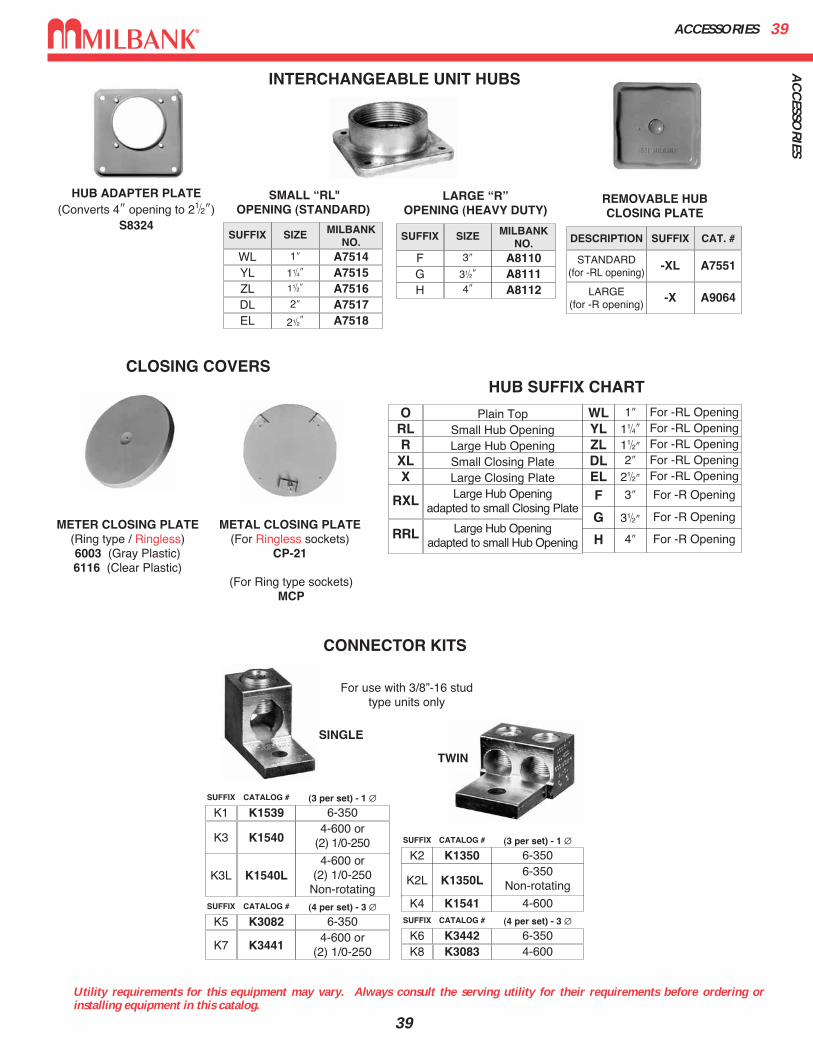
HUB SUFFIX CHART
O Plain Top WL 1″ For -RL OpeningYL 11⁄4″ For -RL OpeningZL 11⁄2″ For -RL OpeningDL 2″ For -RL OpeningELF
G
H
21⁄2″ For -RL Opening
3″ For -R Opening
31⁄2″ For -R Opening
4″ For -R Opening
RL Small Hub OpeningR Large Hub OpeningXL Small Closing PlateX
RXL Large Hub Openingadapted to small Closing Plate
RRL Large Hub Openingadapted to small Hub Opening
Large Closing Plate
HUB ADAPTER PLATE(Converts 4″ opening to 21⁄2″)
S8324
1″WL
SIZESUFFIX MILBANKNO.
YLZLDLEL
A751411⁄4″ A751511⁄2″ A75162″ A7517
21⁄2″ A7518
3″F
SUFFIX SIZE MILBANKNO.
GH
A811031⁄2″ A81114″ A8112
SMALL “RL"OPENING (STANDARD)
LARGE “R”OPENING (HEAVY DUTY)
REMOVABLE HUBCLOSING PLATE
DESCRIPTION SUFFIX CAT. #
STANDARD(for -RL opening)
-XL A7551
LARGE(for -R opening)
-X A9064
For use with 3/8”-16 studtype units only
SINGLE
TWIN
K1350K2 6-350
K1350L
K1541
K2L
K4
6-350 Non-rotating
4-600
CATALOG #SUFFIX (3 per set) - 1 ∅
K3442K6 6-350 K3083K8 4-600
CATALOG #SUFFIX (4 per set) - 3 ∅K3082K5 6-350
K3441K74-600 or
(2) 1/0-250
CATALOG #SUFFIX (4 per set) - 3 ∅
K1539K1 6-350
K1540
K1540L
K3
K3L
4-600 or(2) 1/0-250
4-600 or(2) 1/0-250
Non-rotating
CATALOG #SUFFIX (3 per set) - 1 ∅
CONNECTOR KITS
CLOSING COVERS
METER CLOSING PLATE(Ring type / Ringless)6003 (Gray Plastic)6116 (Clear Plastic)
METAL CLOSING PLATE(For Ringless sockets)
CP-21
(For Ring type sockets)MCP
INTERCHANGEABLE UNIT HUBS
ACCESSORIES40
Utility requirements for this equipment may vary. Always consult the serving utility for their requirements before ordering orinstalling equipment in this catalog.
40
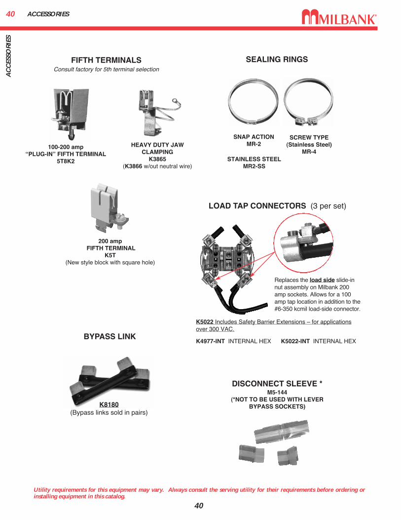
SEALING RINGS
LOAD TAP CONNECTORS (3 per set)
SNAP ACTIONMR-2
STAINLESS STEELMR2-SS
DISCONNECT SLEEVE *M5-144
(*NOT TO BE USED WITH LEVERBYPASS SOCKETS)
SCREW TYPE (Stainless Steel)
MR-4
FIFTH TERMINALS
100-200 amp “PLUG-IN” FIFTH TERMINAL
5T8K2
200 ampFIFTH TERMINAL
K5T(New style block with square hole)
HEAVY DUTY JAWCLAMPING
K3865(K3866 w/out neutral wire)
Consult factory for 5th terminal selection
BYPASS LINK
K8180(Bypass links sold in pairs)
Replaces the load side slide-innut assembly on Milbank 200amp sockets. Allows for a 100amp tap location in addition to the#6-350 kcmil load-side connector.
K5022 Includes Safety Barrier Extensions – for applicationsover 300 VAC.
K4977-INT INTERNAL HEX K5022-INT INTERNAL HEX
AC
CES
SOR
IES

41U
QFP PLU
G–IN
SERIES C
IRC
UIT B
REA
KER
SUQFP PLUG–IN SERIES CIRCUIT BREAKERS
Utility requirements for this equipment may vary. Always consult the serving utility for their requirements before ordering orinstalling equipment in this catalog.
41
#3-#1 #1-1/0
#3-#1 #1-1/0
1/0-300 2/0-300
1/0-300 2/0-300
1/0-300 2/0-300
WIRE RANGE
CU AL
200 AMP FRAME—PLUG-IN—10,000 AIC & 22,000 AICTWO-POLE—COMMON TRIP
UL LISTED: For use with 60°C or 75°C wire.
UQFP: For parallel main circuit breaker applicationsUQFP-M: For series main circuit breaker applications. Split load tab features allow for feed
through capability.STANDARD PACKAGING: 5 units per 16 lb. carton.
UQFP
UQFP-M
AMPS
100 UQFP-100
125 UQFP-125
150 UQFP-150
175 UQFP-175
200 UQFP-200
10K AICPLUG-IN
UQFPH-100
UQFPH-125
UQFPH-150
UQFPH-175
UQFPH-200
22K AICPLUG-IN
UQFP-M-100
UQFP-M-125
UQFP-M-150
UQFP-M-175
UQFP-M-200
10K AICPLUG-IN
UQFPH-M-100
UQFPH-M-125
UQFPH-M-150
UQFPH-M-175
UQFPH-M-200
22K AICPLUG-IN
UQFB BOLT–ON SERIES CIRCUIT BREAKERS42U
QFB
BO
LT–O
N S
ERIE
S C
IRC
UIT
BR
EAK
ERS
Utility requirements for this equipment may vary. Always consult the serving utility for their requirements before ordering orinstalling equipment in this catalog.
42
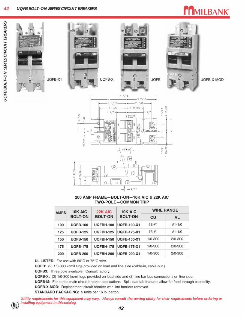
#3-#1 #1-1/0
#3-#1 #1-1/0
1/0-300 2/0-300
1/0-300 2/0-300
1/0-300 2/0-300
WIRE RANGE
CU AL
200 AMP FRAME—BOLT-ON—10K AIC & 22K AICTWO-POLE—COMMON TRIP
UL LISTED: For use with 60°C or 75°C wire.
UQFB: (2) 1/0-300 kcmil lugs provided on load and line side (cable-in, cable-out.)UQFB3: Three pole available. Consult factory.UQFB-X: (2) 1/0-300 kcmil lugs provided on load side and (2) line bar bus connections on line side.UQFB-M: For series main circuit breaker applications. Split load tab features allow for feed through capability.UQFB-X-MOD: Replacement circuit breaker with line barriers removed.STANDARD PACKAGING: 5 units per 16 lb. carton.
UQFB-X UQFB-X-MOD
AMPS
100
125
150
175
200
UQFB-100
UQFB-125
UQFB-150
UQFB-175
UQFB-200
10K AICBOLT-ON
UQFB-100-X1
UQFB-125-X1
UQFB-150-X1
UQFB-175-X1
UQFB-200-X1
10K AICBOLT-ON
UQFBH-100
UQFBH-125
UQFBH-150
UQFBH-175
UQFBH-200
22K AICBOLT-ON
UQFB-X1 UQFB
43C
ON
DU
IT, AM
PAC
ITY &
SCC
R IN
FOR
MA
TION
CONDUIT, AMPACITY & SCCR INFORMATION
43
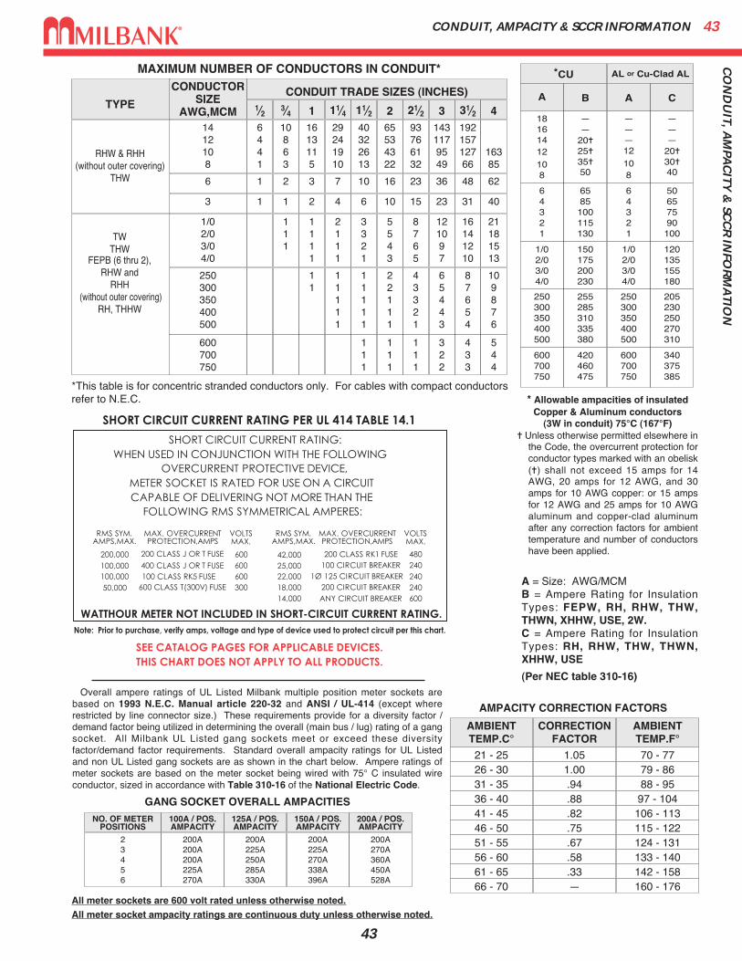
Overall ampere ratings of UL Listed Milbank multiple position meter sockets arebased on 1993 N.E.C. Manual article 220-32 and ANSI / UL-414 (except whererestricted by line connector size.) These requirements provide for a diversity factor /demand factor being utilized in determining the overall (main bus / lug) rating of a gangsocket. All Milbank UL Listed gang sockets meet or exceed these diversityfactor/demand factor requirements. Standard overall ampacity ratings for UL Listedand non UL Listed gang sockets are as shown in the chart below. Ampere ratings ofmeter sockets are based on the meter socket being wired with 75° C insulated wireconductor, sized in accordance with Table 310-16 of the National Electric Code.
TYPE
RHW & RHH(without outer covering)
THW
CONDUCTORSIZE
AWG,MCM1412108
CONDUIT TRADE SIZES (INCHES)1⁄2 3⁄4 1 11⁄4 11⁄2 2 21⁄2 3 31⁄2 46441
10863
1613115
29241910
40322613
65534322
93766132
1431179549
19215712766
16385
6 1 2 3 7 10 16 23 36 48 62
3 1 1 2 4 6 10 15 23 31 40
1/02/03/04/0
250300350400500
600700750
111
1111
2111
3321
5543
8765
121097
16141210
21181513
11
11111
11111
22111
43321
65443
87654
109876
111
111
111
322
433
544
TWTHW
FEPB (6 thru 2),RHW and
RHH(without outer covering)
RH, THHW
*This table is for concentric stranded conductors only. For cables with compact conductorsrefer to N.E.C.
*CU
A
18161412108
64321
1/02/03/04/0
250300350400500
600700750
255285310335380
420460475
——
20�
25�
35�50
6585
100115130
150175200230
B
250300350400500
600700750
———12108
64321
1/02/03/04/0
A
AL or Cu-Clad AL
205230250270310
340375385
———
20�
30�40
50657590100
120135155180
C
AMBIENTTEMP.C°
CORRECTIONFACTOR
AMBIENTTEMP.F°
21 - 25 1.05 70 - 7726 - 30 1.00 79 - 8631 - 35 .94 88 - 9536 - 40 .88 97 - 10441 - 45 .82 106 - 11346 - 50 .75 115 - 12251 - 55 .67 124 - 13156 - 60 .58 133 - 14061 - 65 .33 142 - 15866 - 70 — 160 - 176
* Allowable ampacities of insulatedCopper & Aluminum conductors
(3W in conduit) 75°C (167°F)� Unless otherwise permitted elsewhere in
the Code, the overcurrent protection forconductor types marked with an obelisk(�) shall not exceed 15 amps for 14AWG, 20 amps for 12 AWG, and 30amps for 10 AWG copper: or 15 ampsfor 12 AWG and 25 amps for 10 AWGaluminum and copper-clad aluminumafter any correction factors for ambienttemperature and number of conductorshave been applied.
AMPACITY CORRECTION FACTORS
MAXIMUM NUMBER OF CONDUCTORS IN CONDUIT*
A = Size: AWG/MCMB = Ampere Rating for InsulationTypes: FEPW, RH, RHW, THW,THWN, XHHW, USE, 2W.C = Ampere Rating for InsulationTypes: RH, RHW, THW, THWN,XHHW, USE
(Per NEC table 310-16)
All meter sockets are 600 volt rated unless otherwise noted.All meter socket ampacity ratings are continuous duty unless otherwise noted.
NO. OF METERPOSITIONS
100A / POS.AMPACITY
125A / POS.AMPACITY
150A / POS.AMPACITY
200A / POS.AMPACITY
23456
200A200A200A225A270A
200A225A250A285A330A
200A225A270A338A396A
200A270A360A450A528A
GANG SOCKET OVERALL AMPACITIES
ENERGIZATION OF ELECTRICAL EQUIPMENT44EN
ERG
IZA
TIO
N O
F EL
ECTR
ICA
L EQ
UIP
MEN
T
44
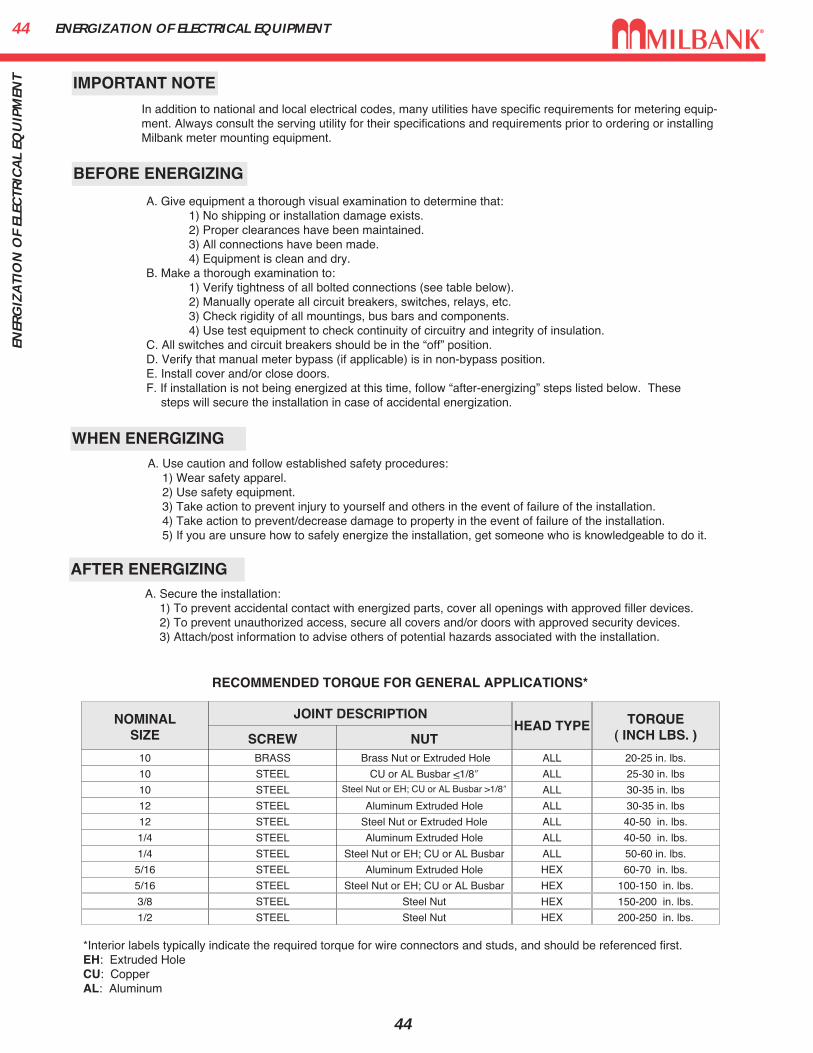
BEFORE ENERGIZING
IMPORTANT NOTE
WHEN ENERGIZING
AFTER ENERGIZING
A. Give equipment a thorough visual examination to determine that:1) No shipping or installation damage exists.2) Proper clearances have been maintained.3) All connections have been made.4) Equipment is clean and dry.
B. Make a thorough examination to:1) Verify tightness of all bolted connections (see table below).2) Manually operate all circuit breakers, switches, relays, etc.3) Check rigidity of all mountings, bus bars and components.4) Use test equipment to check continuity of circuitry and integrity of insulation.
C. All switches and circuit breakers should be in the “off” position.D. Verify that manual meter bypass (if applicable) is in non-bypass position.E. Install cover and/or close doors.F. If installation is not being energized at this time, follow “after-energizing” steps listed below. These
steps will secure the installation in case of accidental energization.
A. Use caution and follow established safety procedures:1) Wear safety apparel.2) Use safety equipment.3) Take action to prevent injury to yourself and others in the event of failure of the installation.4) Take action to prevent/decrease damage to property in the event of failure of the installation.5) If you are unsure how to safely energize the installation, get someone who is knowledgeable to do it.
A. Secure the installation:1) To prevent accidental contact with energized parts, cover all openings with approved filler devices.2) To prevent unauthorized access, secure all covers and/or doors with approved security devices.3) Attach/post information to advise others of potential hazards associated with the installation.
NOMINALSIZE
10
10
10
12
12
1/4
1/4
5/16
JOINT DESCRIPTION
SCREW NUTBRASS
STEEL
STEEL
STEEL
STEEL
STEEL
STEEL
STEEL
Brass Nut or Extruded Hole
CU or AL Busbar <1/8″Steel Nut or EH; CU or AL Busbar >1/8″
Aluminum Extruded Hole
Steel Nut or Extruded Hole
Aluminum Extruded Hole
Steel Nut or EH; CU or AL Busbar
Aluminum Extruded Hole
ALL
ALL
ALL
ALL
ALL
ALL
ALL
HEX
20-25 in. lbs.
25-30 in. lbs
30-35 in. lbs
30-35 in. lbs
40-50 in. lbs.
40-50 in. lbs.
50-60 in. lbs.
60-70 in. lbs.
5/16 STEEL Steel Nut or EH; CU or AL Busbar HEX 100-150 in. lbs.
3/8 STEEL Steel Nut HEX 150-200 in. lbs.
1/2 STEEL Steel Nut HEX 200-250 in. lbs.
HEAD TYPE TORQUE( INCH LBS. )
*Interior labels typically indicate the required torque for wire connectors and studs, and should be referenced first.EH: Extruded HoleCU: CopperAL: Aluminum
RECOMMENDED TORQUE FOR GENERAL APPLICATIONS*
In addition to national and local electrical codes, many utilities have specific requirements for metering equip-ment. Always consult the serving utility for their specifications and requirements prior to ordering or installingMilbank meter mounting equipment.
45M
ATER
IALS A
ND
FINISH
ESMATERIALS AND FINISHES
45
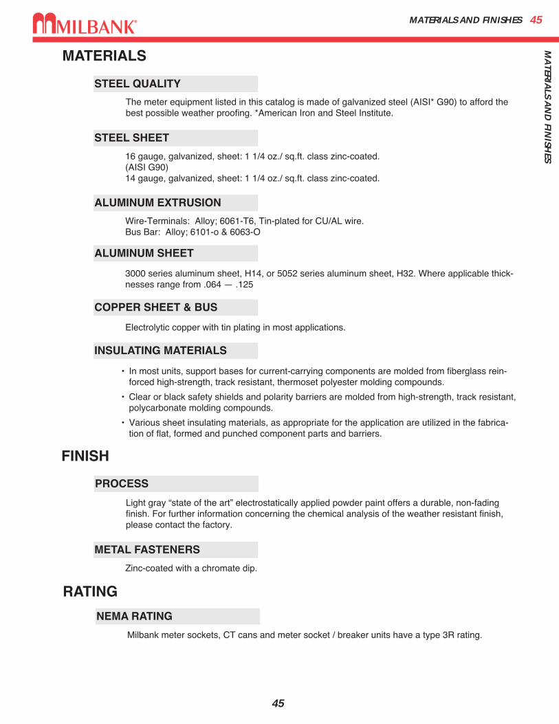
MATERIALS
STEEL SHEET
STEEL QUALITY
ALUMINUM EXTRUSION
ALUMINUM SHEET
COPPER SHEET & BUS
INSULATING MATERIALS
PROCESS
METAL FASTENERS
The meter equipment listed in this catalog is made of galvanized steel (AISI* G90) to afford thebest possible weather proofing. *American Iron and Steel Institute.
Light gray “state of the art” electrostatically applied powder paint offers a durable, non-fadingfinish. For further information concerning the chemical analysis of the weather resistant finish,please contact the factory.
Wire-Terminals: Alloy; 6061-T6, Tin-plated for CU/AL wire.Bus Bar: Alloy; 6101-o & 6063-O
3000 series aluminum sheet, H14, or 5052 series aluminum sheet, H32. Where applicable thick-nesses range from .064 — .125
Electrolytic copper with tin plating in most applications.
Zinc-coated with a chromate dip.
• In most units, support bases for current-carrying components are molded from fiberglass rein-forced high-strength, track resistant, thermoset polyester molding compounds.
• Clear or black safety shields and polarity barriers are molded from high-strength, track resistant,polycarbonate molding compounds.
• Various sheet insulating materials, as appropriate for the application are utilized in the fabrica-tion of flat, formed and punched component parts and barriers.
16 gauge, galvanized, sheet: 1 1/4 oz./ sq.ft. class zinc-coated.(AISI G90)14 gauge, galvanized, sheet: 1 1/4 oz./ sq.ft. class zinc-coated.
FINISH
NEMA RATING
Milbank meter sockets, CT cans and meter socket / breaker units have a type 3R rating.
RATING

METER FORMS46M
ETER
FO
RM
S
46
DIAGRAM A
(ALT.LOC.)
++
+
+
ILINE
(BONDED)N C.T. LOAD
P1 PN C+1 C1
P.T.
++
1LINE
C.T.LOAD2
P1 C+1
++
3
++
PT PT
DIAGRAM E
P3 P2 C1 C+3 C3
C.T.
++
1LINE
C.T.LOAD2
P1 C+1
++
3
DIAGRAM F
P3 P2 C1 C+3 C3
C.T.
+
+
1
LINE
C.T.LOAD2
P1
+
+3
PN C+
N
C.T.
C.T.
+
+
(BONDED)
+ +PT PT
++
P3
PT
+ +
DIAGRAM J
P2 C C+ C C+ C
+
+
C.T.LOAD
P1
+
+
P3 PN C+ C+
C.T.
C.T.
++
(BONDED)
DIAGRAM G
C C C+ C
1
LINE23N
+
+
1
LINE
C.T.LOAD2
P1
+
+3
P3 PN C+
N
C.T.
C.T.
++
(BONDED)
+ +
PTPT
+ +
DIAGRAM H
C C+C+ CC
+
+
1
LINE
C.T.LOAD2
P1
+
+3
P3 PN C+
N
C.T.
C.T.
++
(BONDED)
P2
DIAGRAM I
C C+ C C+ C
(ALT.LOC.)
++I
LINE
(BONDED)N C.T.
LOAD2
DIAGRAM B
P1 PN C+1 C1
++
ILINE
(BONDED)NC.T.
LOAD
2
P1 P2 C+1 C+
2 C2C+2
++
DIAGRAM C
C.T.
++
ILINE
(BONDED)NC.T.
LOAD
2 ++
DIAGRAM D
P1 P2 C+1 C2C+
2PN C1
C.T.
DIAGRAM D1∅3W or 3W Network with 2 C.T.ʼs
2 Stator Meter – Form 5S8T Socket, Test Switch #TS07-0105
DIAGRAM E3∅3W “Δ” with 2 P.T.ʼs & 2 C.T.ʼs
2 Stator Meter – Form 5S8T Socket, Test Switch #TS07-0105
DIAGRAM F3∅3W “Δ” with 2 C.T.ʼs
2 Stator Meter – Form 5S8T Socket, Test Switch #TS07-0105
DIAGRAM G3∅4W “Y” with 3 C.T.ʼs
2 1⁄2 Stator Meter – Form 6S13T Socket, Test Switch #TS10-0109
DIAGRAM H3∅4W “Y” with 2 P.T.ʼs & 3 C.T.ʼs
2 1⁄2 Stator Meter – Form 6S13T Socket, Test Switch #TS10-0109
DIAGRAM I3∅4W “Y” or “Δ” with 3 C.T.ʼs“Y” 3 Stator Meter – Form 9S“Δ” 2 Stator Meter – Form 8S
13T Socket, Test Switch #TS10-0109
DIAGRAM J3∅4W “Y” with 3 P.T.ʼs & 3 C.T.ʼs
3 Stator Meter – Form 9S13T Socket, Test Switch #TS10-0109
DIAGRAM A1∅2W with 1 P.T. & 1 C.T.
Single Stator Meter(2W1∅) – Form 3S5T Socket, Test Switch #TS04-0101
DIAGRAM B1∅3W with 1 C.T.
Single Stator Meter(2W1∅) – Form 3S5T Socket, Test Switch #TS04-0101
DIAGRAM C1∅3W with 2 C.T.ʼs
Single Stator Meter(3W1∅) – Form 4S6T Socket, Test Switch #TS07-0105
PREWIRING: If standard factory prewiring isrequired, refer to wiring diagrams on this page.Determine appropriate diagram and send acopy with order. If custom factory prewiring isrequired, specify on order. Be sure to includemeter socket catalog number, test switch makeand catalog number, meter form number andprovide a copy of your wiring diagram.
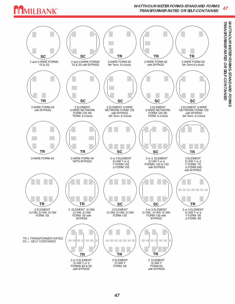
47W
ATTH
OU
R M
ETER FO
RM
S–STAN
DA
RD
FOR
MS
TRA
NSFO
RM
ER R
ATED
OR
SELF-CO
NTA
INED
WATTHOUR METER FORMS–STANDARD FORMSTRANSFORMER RATED OR SELF-CONTAINED
47
SC SC TR TR TR
TR SC SC SC SC
TR TR SC SC TR
TR TR SC SC TR
TR TR TR
2 and 3-WIRE FORMS 1S & 2S
2 and 3-WIRE FORMS 1S & 2S with BYPASS
2-WIRE FORM 3S 5th Term. 9 o'clock
2-WIRE FORM 3S with BYPASS
2-WIRE FORM 3S 5th Term.6 o'clock
2-WIRE FORM 3S with BYPASS
2 ELEMENT 3-WIRE NETWORK
FORM 12S 5th TERM. 9 o'clock
2 ELEMENT 3-WIRE NETWORK FORM 12S
with BYPASS 5th Term. 9 o'clock
2 ELEMENT 3-WIRE NETWORK FORM 12S
with BYPASS5th Term. 6 o'clock
2 ELEMENT 3-WIRE NETWORK
FORM 12S 5th TERM. 6 o'clock
3-WIRE FORM 4S 3-WIRE FORM 4S WITH BYPASS
2 or 3 ELEMENT 3∅4W Y or ∆ Y FORM 14S ∆ FORM 15S
2 or 3 ELEMENT 3∅4W Y or ∆
FORMS 14S & 15Swith BYPASS
2 ELEMENT 3∅4W Y or ∆ Y FORM 7S ∆ FORM 24S
with BYPASS
2 ELEMENT 2∅3W, 2∅4W, 3∅3W
FORM 5S
2 ELEMENT 2∅3W, 2∅4W, 3∅3WFORM 5S with
BYPASS
2 ELEMENT 2∅3W, 2∅4W, 3∅3W
FORM 13S
2 or 3 ELEMENT 2∅3W, 2∅4W, 3∅3W
FORM 13S with BYPASS
2 or 3 ELEMENT 3∅4W Y or ∆ Y FORM 9S ∆ FORM 8S
2 or 3 ELEMENT 3∅4W Y or ∆
FORMS 8S & 9Swith BYPASS
2 ELEMENT 3∅4W Y
FORM 6S
2 ELEMENT 3∅4W Y
FORM 6Swith BYPASS
TR = TRANSFORMER RATEDSC = SELF CONTAINED
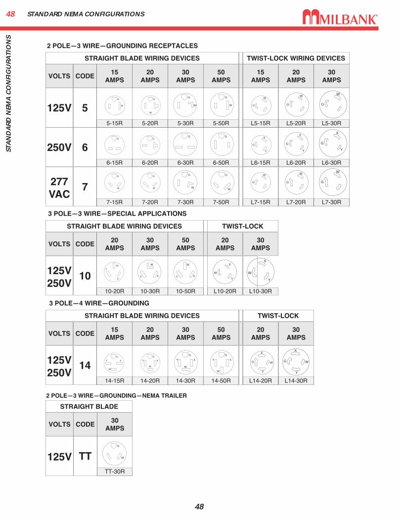
STANDARD NEMA CONFIGURATIONS48ST
AN
DA
RD
NEM
A C
ON
FIG
UR
ATI
ON
S
48
125V 5
250V 6
277VAC
7
2 POLE—3 WIRE—GROUNDING RECEPTACLES
3 POLE—3 WIRE—SPECIAL APPLICATIONS
3 POLE—4 WIRE—GROUNDING
VOLTS
STRAIGHT BLADE WIRING DEVICES TWIST-LOCK WIRING DEVICES
CODE20
AMPS30
AMPS50
AMPS15
AMPS20
AMPS30
AMPS15
AMPS
5-15R 5-20R 5-30R 5-50R L5-15R L5-20R L5-30R
125V250V
10
VOLTS
STRAIGHT BLADE WIRING DEVICES TWIST-LOCK
CODE20
AMPS30
AMPS50
AMPS20
AMPS30
AMPS
10-20R 10-30R 10-50R L10-20R L10-30R
125V250V
14
VOLTS
STRAIGHT BLADE WIRING DEVICES TWIST-LOCK
CODE20
AMPS30
AMPS50
AMPS20
AMPS30
AMPS15
AMPS
14-15R 14-20R 14-30R 14-50R L14-20R L14-30R
6-15R 6-20R 6-30R 6-50R L6-15R L6-20R L6-30R
7-15R 7-20R 7-30R 7-50R L7-15R L7-20R L7-30R
G
W
G
G
W
G
G
W
G
W
G
W
G
G
W
G
W
G
G
W
G
W
G
X
Y
G
W
G
W
G
X
Y
G
W
G
W
G
X
Y
G
W
W
X
Y
W
XY
W
XY
X
W
Y
X
W
Y
G
W
Y X
G
W
Y X
G
W
Y X
G
W
Y X
X
W
Y
G
X
W
Y
G
2 POLE—3 WIRE—GROUNDING—NEMA TRAILER
125V TT
VOLTS
STRAIGHT BLADE
CODE30
AMPS
TT-30R
G
W
49IN
DEX
INDEX
49
SKU PAGE # SKU PAGE # SKU PAGE #
363010-CT3R . . . . . . . . . . . . . . . . . . 38363016-CT3R . . . . . . . . . . . . . . . . . . 38363610-CT3R . . . . . . . . . . . . . . . . . . 38363612-CT3R . . . . . . . . . . . . . . . . . . 38363616-CT3R . . . . . . . . . . . . . . . . . . 38483616-CT3R . . . . . . . . . . . . . . . . . . 38484812-CT3R . . . . . . . . . . . . . . . . . . 385T8K2 . . . . . . . . . . . . . . . . . . . . . . . . 406003 . . . . . . . . . . . . . . . . . . . . . . . . . 39606013-CT3R . . . . . . . . . . . . . . . . . . 386116 . . . . . . . . . . . . . . . . . . . . . . . . . 39A7514 . . . . . . . . . . . . . . . . . . . . . . . . 39A7515 . . . . . . . . . . . . . . . . . . . . . . . . 39A7516 . . . . . . . . . . . . . . . . . . . . . . . . 39A7517 . . . . . . . . . . . . . . . . . . . . . . . . 39A7518 . . . . . . . . . . . . . . . . . . . . . . . . 39A7551 . . . . . . . . . . . . . . . . . . . . . . . . 39A8110 . . . . . . . . . . . . . . . . . . . . . . . . 39A8111 . . . . . . . . . . . . . . . . . . . . . . . . 39A8112 . . . . . . . . . . . . . . . . . . . . . . . . 39A9064 . . . . . . . . . . . . . . . . . . . . . . . . 39CP-21 . . . . . . . . . . . . . . . . . . . . . . . . 39K1350 . . . . . . . . . . . . . . . . . . . . . . . . 39K1350L . . . . . . . . . . . . . . . . . . . . . . . 39K1539 . . . . . . . . . . . . . . . . . . . . . . . . 39K1540 . . . . . . . . . . . . . . . . . . . . . . . . 39K1540L . . . . . . . . . . . . . . . . . . . . . . . 39K1541 . . . . . . . . . . . . . . . . . . . . . . . . 39K3082 . . . . . . . . . . . . . . . . . . . . . . . . 39K3083 . . . . . . . . . . . . . . . . . . . . . . . . 39K3441 . . . . . . . . . . . . . . . . . . . . . . . . 39K3442 . . . . . . . . . . . . . . . . . . . . . . . . 39K3450 . . . . . . . . . . . . . . . . . . . . . . . . 33K3865 . . . . . . . . . . . . . . . . . . . . . . . . 40K5035 . . . . . . . . . . . . . . . . . . . . . . . . 33K5193 . . . . . . . . . . . . . . . . . . . . . . . . 33K5194 . . . . . . . . . . . . . . . . . . . . . . . . 33K5400-1450 . . . . . . . . . . . . . . . . . . . . 33K5400-1450GB . . . . . . . . . . . . . . . . . 35K5400-520GR . . . . . . . . . . . . . . . . . . 33K5400-620 . . . . . . . . . . . . . . . . . . . . . 35K5400-620GB . . . . . . . . . . . . . . . . . . 35K5400-BRIDGE-1POS . . . . . . . . . . . 33K5400-BRIDGE-2POS . . . . . . . . . . . 33K5400-TT30 . . . . . . . . . . . . . . . . . . . 33K5415 . . . . . . . . . . . . . . . . . . . . . . . . 33K5T . . . . . . . . . . . . . . . . . . . . . . . . . . 33K8180 . . . . . . . . . . . . . . . . . . . . . . . . 40M5-144 . . . . . . . . . . . . . . . . . . . . . . . 40MCP . . . . . . . . . . . . . . . . . . . . . . . . . 39MR-2 . . . . . . . . . . . . . . . . . . . . . . . . . 40MR-2-SS . . . . . . . . . . . . . . . . . . . . . . 40MR-4 . . . . . . . . . . . . . . . . . . . . . . . . . 40NU8980-O-200-KK . . . . . . . . . . . . . . 28NU8980-O-200-KK-LP . . . . . . . . . . . 28NU8980-O-KK . . . . . . . . . . . . . . . . . . 28
NU8980-O-KK-LP . . . . . . . . . . . . . . . 28NU8980-O-SF100-KK . . . . . . . . . . . . 28NU8980-O-SF100-KK-LP . . . . . . . . . 28S1890-XT . . . . . . . . . . . . . . . . . . . . . 26S1891-XT . . . . . . . . . . . . . . . . . . . . . 26S2674-XT . . . . . . . . . . . . . . . . . . . . . 26S2690-XT . . . . . . . . . . . . . . . . . . . . . 26S2777-XT . . . . . . . . . . . . . . . . . . . . . 27S2811-XT . . . . . . . . . . . . . . . . . . . . . 27S3831-XT . . . . . . . . . . . . . . . . . . . . . 26S3912-XT . . . . . . . . . . . . . . . . . . . . . 26U1079-R . . . . . . . . . . . . . . . . . . . . . . 11U1748-O . . . . . . . . . . . . . . . . . . . . . . 29U1779-RRL-K3-K2 . . . . . . . . . . . . . . 11U1797-O-K3L-K2L . . . . . . . . . . . . . . 11U1980-O . . . . . . . . . . . . . . . . . . . . . . . 5U2161-XT . . . . . . . . . . . . . . . . . . . . . 25U2228-XT . . . . . . . . . . . . . . . . . . . . . 25U2229-XT . . . . . . . . . . . . . . . . . . . . . 25U2594-X . . . . . . . . . . . . . . . . . . . . . . 12U3499-RL . . . . . . . . . . . . . . . . . . . . . 13U3499-XL-100 . . . . . . . . . . . . . . . . . . 13U3849-O-2/200 . . . . . . . . . . . . . . . . . 29U4031-O-2/200 . . . . . . . . . . . . . . . . . 18U4322-O-5T9 . . . . . . . . . . . . . . . . . . 36U4493-XL . . . . . . . . . . . . . . . . . . . . . 24U4505-X . . . . . . . . . . . . . . . . . . . . . . 10U4532-XL . . . . . . . . . . . . . . . . . . . . . . 6U4540-XL . . . . . . . . . . . . . . . . . . . . . 37U4542-XL . . . . . . . . . . . . . . . . . . . . . 37U4544-XL . . . . . . . . . . . . . . . . . . . . . 37U4546-XL . . . . . . . . . . . . . . . . . . . . . 37U4548-XL . . . . . . . . . . . . . . . . . . . . . 37U4549-XL . . . . . . . . . . . . . . . . . . . . . 37U4702-X . . . . . . . . . . . . . . . . . . . . . . 10U4834-XL-200-5T9 . . . . . . . . . . . . . . 21U5059-X-2/200-K3L . . . . . . . . . . . . . 19U5067-X-2/200 . . . . . . . . . . . . . . . . . 30U5067-X-2/225 . . . . . . . . . . . . . . . . . 30U5136-O . . . . . . . . . . . . . . . . . . . . . . 33U5136-O-100S . . . . . . . . . . . . . . . . . 33U5136-O-200S . . . . . . . . . . . . . . . . . 33U5137-O . . . . . . . . . . . . . . . . . . . . . . 33U5137-O-100S . . . . . . . . . . . . . . . . . 33U5137-O-200S . . . . . . . . . . . . . . . . . 33U5138-O . . . . . . . . . . . . . . . . . . . . . . 33U5138-O-200S . . . . . . . . . . . . . . . . . 33U5168-XTL-200 . . . . . . . . . . . . . . . . . 16U5169-XTL-200 . . . . . . . . . . . . . . . . . 16U5268-XTL-200 . . . . . . . . . . . . . . . . . 16U5269-XTL-200 . . . . . . . . . . . . . . . . . 16U5706-O-200S . . . . . . . . . . . . . . . . . 35U5706-O-200S-KK . . . . . . . . . . . . . . 35U5712-XL-200 . . . . . . . . . . . . . . . . . . 17U7017-RL-TG . . . . . . . . . . . . . . . . . . . 7U7018-XL-TG . . . . . . . . . . . . . . . . . . . 7
U7021-RL-TG . . . . . . . . . . . . . . . . . . . 5U7040-RL-TG . . . . . . . . . . . . . . . . . . . 5U7043-XL-TG . . . . . . . . . . . . . . . . . . . 6U7487-RL-TG . . . . . . . . . . . . . . . . . . . 4U7490-RL-TG . . . . . . . . . . . . . . . . . . . 4U8144-XL . . . . . . . . . . . . . . . . . . . . . 13U8303-O . . . . . . . . . . . . . . . . . . . . . . 31U8436-O . . . . . . . . . . . . . . . . . . . . . . 31U9550-RRL . . . . . . . . . . . . . . . . . . . . . 8U9551-RXL . . . . . . . . . . . . . . . . . . . . . 8U9581-RXL-QG . . . . . . . . . . . . . . . . . . 9U9647N-RL-200 . . . . . . . . . . . . . . . . 14U9648-RL-100 . . . . . . . . . . . . . . . . . . 14U9700-RRL . . . . . . . . . . . . . . . . . . . . . 8U9701-RXL . . . . . . . . . . . . . . . . . . . . . 8U9800-RRL . . . . . . . . . . . . . . . . . . . . . 8U9801-RXL . . . . . . . . . . . . . . . . . . . . . 8UAP5024-XL . . . . . . . . . . . . . . . . . . . 15UC7237-RL . . . . . . . . . . . . . . . . . . . . 22UC7449-XL . . . . . . . . . . . . . . . . . . . . 23UC7545-RL . . . . . . . . . . . . . . . . . . . . 22UQFB-100 . . . . . . . . . . . . . . . . . . . . . 42UQFB-100-X1 . . . . . . . . . . . . . . . . . . 42UQFB-125 . . . . . . . . . . . . . . . . . . . . . 42UQFB-125-X1 . . . . . . . . . . . . . . . . . . 42UQFB-150 . . . . . . . . . . . . . . . . . . . . . 42UQFB-150-X1 . . . . . . . . . . . . . . . . . . 42UQFB-175 . . . . . . . . . . . . . . . . . . . . . 42UQFB-175-X1 . . . . . . . . . . . . . . . . . . 42UQFB-200 . . . . . . . . . . . . . . . . . . . . . 42UQFB-200-X1 . . . . . . . . . . . . . . . . . . 42UQFBH-100 . . . . . . . . . . . . . . . . . . . 42UQFBH-125 . . . . . . . . . . . . . . . . . . . 42UQFBH-150 . . . . . . . . . . . . . . . . . . . 42UQFBH-175 . . . . . . . . . . . . . . . . . . . 42UQFBH-200 . . . . . . . . . . . . . . . . . . . 42UQFP-100 . . . . . . . . . . . . . . . . . . . . . 41UQFP-125 . . . . . . . . . . . . . . . . . . . . . 41UQFP-150 . . . . . . . . . . . . . . . . . . . . . 41UQFP-175 . . . . . . . . . . . . . . . . . . . . . 41UQFP-200 . . . . . . . . . . . . . . . . . . . . . 41UQFPH-100 . . . . . . . . . . . . . . . . . . . 41UQFPH-125 . . . . . . . . . . . . . . . . . . . 41UQFPH-150 . . . . . . . . . . . . . . . . . . . 41UQFPH-175 . . . . . . . . . . . . . . . . . . . 41UQFPH-200 . . . . . . . . . . . . . . . . . . . 41UQFPH-M-100 . . . . . . . . . . . . . . . . . 41UQFPH-M-125 . . . . . . . . . . . . . . . . . 41UQFPH-M-150 . . . . . . . . . . . . . . . . . 41UQFPH-M-175 . . . . . . . . . . . . . . . . . 41UQFPH-M-200 . . . . . . . . . . . . . . . . . 41UQFP-M-100 . . . . . . . . . . . . . . . . . . . 41UQFP-M-125 . . . . . . . . . . . . . . . . . . . 41UQFP-M-150 . . . . . . . . . . . . . . . . . . . 41UQFP-M-175 . . . . . . . . . . . . . . . . . . . 41UQFP-M-200 . . . . . . . . . . . . . . . . . . . 41
REC/MUNICIPAL CATALOG SKU INDEX BY PAGE #
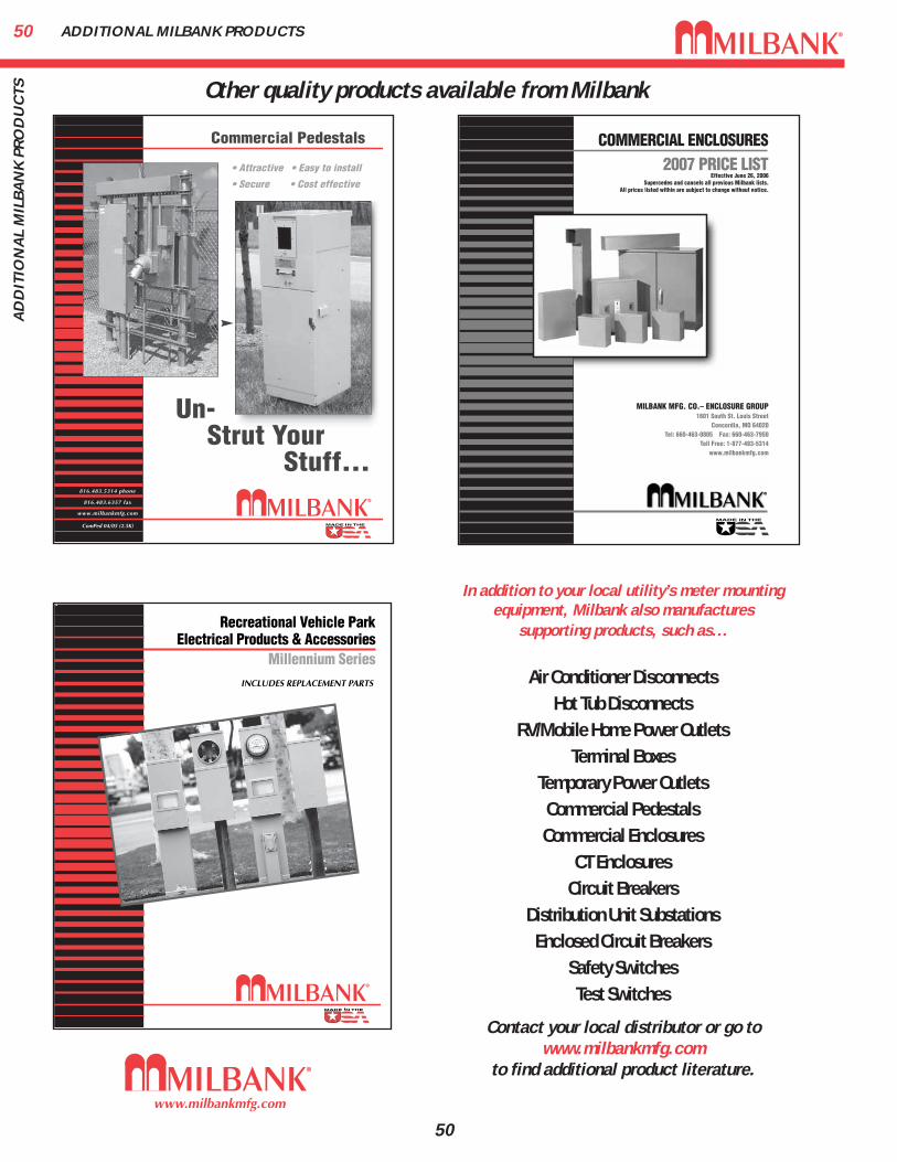
ADDITIONAL MILBANK PRODUCTS50A
DD
ITIO
NA
L M
ILB
AN
K P
RO
DU
CTS
50
COMMERCIAL ENCLOSURES
2007 PRICE LISTEffective June 26, 2006
Supercedes and cancels all previous Milbank lists.All prices listed within are subject to change without notice.
MILBANK MFG. CO.– ENCLOSURE GROUP1601 South St. Louis Street
Concordia, MO 64020Tel: 660-463-0805 Fax: 660-463-7950
Toll Free: 1-877-483-5314www.milbankmfg.com
In addition to your local utility’s meter mountingequipment, Milbank also manufactures
supporting products, such as...
Air Conditioner DisconnectsHot Tub Disconnects
RV/Mobile Home Power OutletsTerminal Boxes
Temporary Power OutletsCommercial PedestalsCommercial Enclosures
CT EnclosuresCircuit Breakers
Distribution Unit SubstationsEnclosed Circuit Breakers
Safety SwitchesTest Switches
Contact your local distributor or go towww.milbankmfg.com
to find additional product literature.
Other quality products available from Milbank

51N
OTES
NOTES
51

Meter Mounting Equipment & More!Commercial Electrical Enclosures
Residential & Commercial Metering
Commercial Meter Pedestals
Disconnect Devices
Current Transformer Enclosures
RV/MH Pedestals
Temporary Power Outlets
Circuit Breakers
Distribution Unit Substations
Enclosed Circuit Breakers
Safety Switches
Test Switches
REPRESENTATIVE
DISTRIBUTOR
www.milbankmfg.com
MILBANK MFG. CO.PO Box 419028Kansas City, MO 64141-0028Tel: 816-483-5314 Fax: 816-483-6357Toll Free: 877-483-5314www.milbankmfg.com
REC 12/09 (WEB)


![Flughafen International · 'dq]ljhu 6wud h % )oxjkdihqvwud h 6wrfnxphu +|ih /lolhqwkdovwud h)oxjkdihqvwud h )oxjkdihqvwud h)oxjkdihqvwud h)oxjkdihqvwud h terminal ring](https://static.fdocuments.net/doc/165x107/5e87de6799a693496d189ac4/flughafen-international-dqljhu-6wud-h-oxjkdihqvwud-h-6wrfnxphu-ih-lolhqwkdovwud.jpg)