Receptacles for the Industry - BLW Visser · Receptacles for the Refrigerated Container Industry...
26
Plugs, Connectors & Receptacles for the Refrigerated Container Industry Effective February 2004
Transcript of Receptacles for the Industry - BLW Visser · Receptacles for the Refrigerated Container Industry...
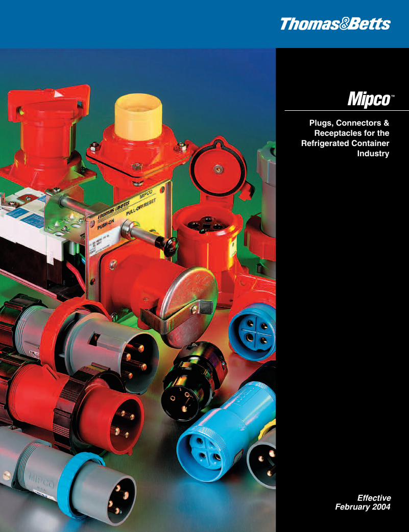
Plugs, Connectors &Receptacles for the
Refrigerated ContainerIndustry
Effective February 2004
Thomas & Betts CorporationElectrical Division8155 T&B BoulevardMemphis, Tennessee 38125
Thomas & Betts Ltd.700 Thomas AvenueIberville, Québec J2X 2M9
For U.S. Customer Service and Order Inquiries, call 1-800-816-7809 or fax 1-800-816-7810.For International Service and Order Inquiries, call (U.S.) 901-252-5400 or fax 901-252-1330.For Canadian Customer Service and Order Inquiries, call 450-347-5318 or fax 450-347-1976.
For U.S. Technical Support, call 1-888-862-3289 or fax 901-252-1321.For International Technical Support, call (U.S.) 901-252-5000, enter 1, 6672.For tool service and repair, call 1-800-284-TOOL (8665).
Call 1-800-858-6022 for our toll-free 24-hour Fax-On-Demand service for technical documentation, brochures and product literature or contact our internet site at www.tnb.com.
© 2004 Thomas & Betts Corporation. All rights reserved. Printed in U.S.A. 2/04 Order No. GM-MP100
602110.CV 3/16/04 3:27 PM Page 1
jva
blw
© 2004 Thomas & Betts Corporation. Specifications are subject to change without notice. www.tnb.com 1
™
™
On Ship, On track orDockside…Worldwide
Manufacturing Quality Systems
Certified to ISO-9001
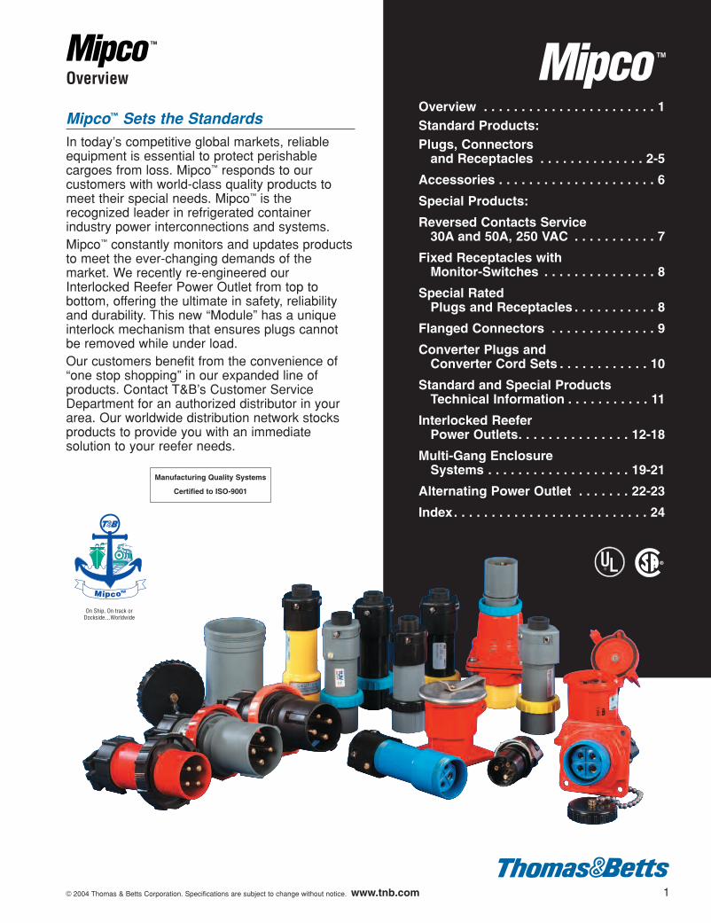
Overview . . . . . . . . . . . . . . . . . . . . . . . 1Standard Products:Plugs, Connectors
and Receptacles . . . . . . . . . . . . . . 2-5
Accessories . . . . . . . . . . . . . . . . . . . . . 6
Special Products:
Reversed Contacts Service30A and 50A, 250 VAC . . . . . . . . . . . 7
Fixed Receptacles withMonitor-Switches . . . . . . . . . . . . . . . 8
Special RatedPlugs and Receptacles . . . . . . . . . . . 8
Flanged Connectors . . . . . . . . . . . . . . 9
Converter Plugs andConverter Cord Sets . . . . . . . . . . . . 10
Standard and Special ProductsTechnical Information . . . . . . . . . . . 11
Interlocked Reefer Power Outlets. . . . . . . . . . . . . . . 12-18
Multi-Gang EnclosureSystems . . . . . . . . . . . . . . . . . . . 19-21
Alternating Power Outlet . . . . . . . 22-23
Index. . . . . . . . . . . . . . . . . . . . . . . . . . 24
Overview
Mipco™ Sets the StandardsIn today’s competitive global markets, reliableequipment is essential to protect perishablecargoes from loss. Mipco™ responds to ourcustomers with world-class quality products tomeet their special needs. Mipco™ is therecognized leader in refrigerated containerindustry power interconnections and systems.Mipco™ constantly monitors and updates productsto meet the ever-changing demands of themarket. We recently re-engineered ourInterlocked Reefer Power Outlet from top tobottom, offering the ultimate in safety, reliabilityand durability. This new “Module” has a uniqueinterlock mechanism that ensures plugs cannotbe removed while under load.Our customers benefit from the convenience of“one stop shopping” in our expanded line ofproducts. Contact T&B’s Customer ServiceDepartment for an authorized distributor in yourarea. Our worldwide distribution network stocksproducts to provide you with an immediatesolution to your reefer needs.
602110.01_3-16 3/16/04 3:28 PM Page 1
2 © 2004 Thomas & Betts Corporation. Specifications are subject to change without notice. www.tnb.com
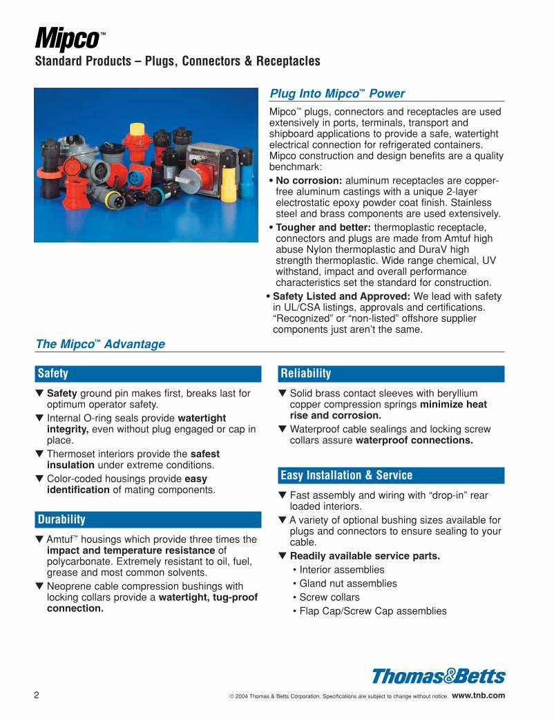
Plug Into Mipco™ PowerMipco™ plugs, connectors and receptacles are usedextensively in ports, terminals, transport andshipboard applications to provide a safe, watertightelectrical connection for refrigerated containers.Mipco construction and design benefits are a qualitybenchmark:• No corrosion: aluminum receptacles are copper-
free aluminum castings with a unique 2-layerelectrostatic epoxy powder coat finish. Stainlesssteel and brass components are used extensively.
• Tougher and better: thermoplastic receptacle,connectors and plugs are made from Amtuf highabuse Nylon thermoplastic and DuraV highstrength thermoplastic. Wide range chemical, UVwithstand, impact and overall performancecharacteristics set the standard for construction.
• Safety Listed and Approved: We lead with safetyin UL/CSA listings, approvals and certifications.“Recognized” or “non-listed” offshore suppliercomponents just aren’t the same.
Safety
▼ Safety ground pin makes first, breaks last foroptimum operator safety.
▼ Internal O-ring seals provide watertightintegrity, even without plug engaged or cap inplace.
▼ Thermoset interiors provide the safestinsulation under extreme conditions.
▼ Color-coded housings provide easyidentification of mating components.
Durability
▼ Amtuf™ housings which provide three times theimpact and temperature resistance ofpolycarbonate. Extremely resistant to oil, fuel,grease and most common solvents.
▼ Neoprene cable compression bushings withlocking collars provide a watertight, tug-proofconnection.
Reliability
▼ Solid brass contact sleeves with berylliumcopper compression springs minimize heatrise and corrosion.
▼ Waterproof cable sealings and locking screwcollars assure waterproof connections.
Easy Installation & Service
▼ Fast assembly and wiring with “drop-in” rearloaded interiors.
▼ A variety of optional bushing sizes available forplugs and connectors to ensure sealing to yourcable.
▼ Readily available service parts.• Interior assemblies• Gland nut assemblies• Screw collars• Flap Cap/Screw Cap assemblies
Standard Products – Plugs, Connectors & Receptacles
The Mipco™ Advantage
602110.01_3-16 3/16/04 3:28 PM Page 2
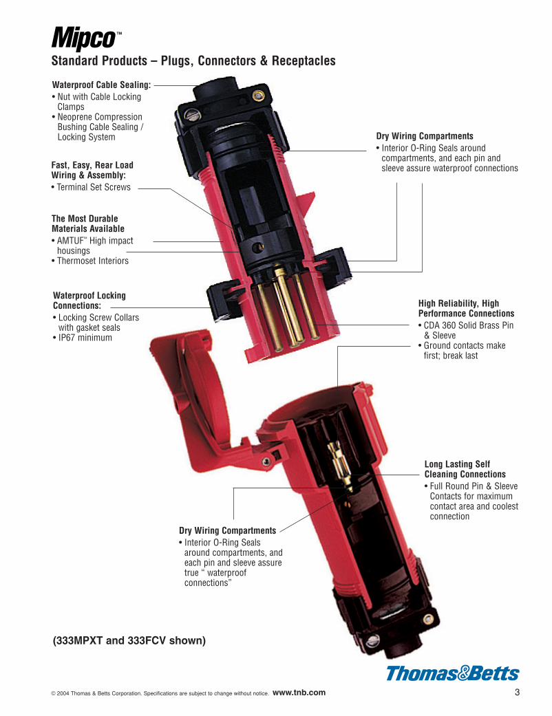
Waterproof Cable Sealing:• Nut with Cable Locking
Clamps• Neoprene Compression
Bushing Cable Sealing /Locking System
Fast, Easy, Rear LoadWiring & Assembly:• Terminal Set Screws
Waterproof LockingConnections:• Locking Screw Collars
with gasket seals• IP67 minimum
Dry Wiring Compartments• Interior O-Ring Seals around
compartments, and each pin andsleeve assure waterproof connections
The Most Durable Materials Available• AMTUF™ High impact
housings• Thermoset Interiors
High Reliability, HighPerformance Connections• CDA 360 Solid Brass Pin
& Sleeve• Ground contacts make
first; break last
Long Lasting SelfCleaning Connections• Full Round Pin & Sleeve
Contacts for maximumcontact area and coolestconnection
Dry Wiring Compartments• Interior O-Ring Seals
around compartments, andeach pin and sleeve assuretrue “ waterproofconnections”
© 2004 Thomas & Betts Corporation. Specifications are subject to change without notice. www.tnb.com 3
Standard Products – Plugs, Connectors & Receptacles
(333MPXT and 333FCV shown)
602110.01_3-16 3/16/04 3:28 PM Page 3
4 © 2004 Thomas & Betts Corporation. Specifications are subject to change without notice. www.tnb.com
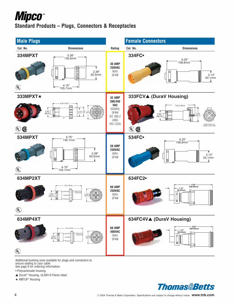
Male PlugsCat. No. Dimensions
Female ConnectorsCat. No. Dimensions
334MPXT
333MPXT★
534MPXT
634MP2XT
634MP4XT
334FC•
333FCV▲ (DuraV Housing)
534FC•
634FC2•
634FC4V▲ (DuraV Housing)
30 AMP250VAC
60Hz3P4W
60 AMP250VAC
60Hz3P4W
50 AMP250VAC
60Hz3P4W
60 AMP480VAC
60Hz3P4W
32 AMP380/440
VAC50/60Hz3P4W
IEC 309-2(480)
VAC-USA)
Standard Products – Plugs, Connectors & Receptacles
5.38"136.6mm
2.38"60.5mm
4.16"105.7mm
6.50 (165.1)
2.62(66.5)
ÿ 2.25(57.2)
2.48(63)
3.75(95.3)
5.75"146.1mm
2.38"60.5mm
4.16"105.7mm
7.50 (190.5)
2.62(66.5)
ÿ 3.80(96.5)
7.50 (190.5)
2.62(66.5)
ÿ 3.80(96.5)
6.25"158.8mm
2.13"54.1mm
7.50 (190.5)
2.62(66.5)
3.63(92.2)
Snap Cap is notShown in this View
6.25"158.8mm
2.13"54.1mm
1.12"28.45mm
9.00"228.60mm
1.12"28.45mm
9.00"228.60mm
¤
¤¤
¤
¤
¤
¤¤
Additional bushing sizes available for plugs and connectors toensure sealing to your cable. See page 6 for ordering information.• Polycarbonate housing.▲ DuraV™ Housing, UL94V-0 Flame rated.★ AMTUF® Housing
Rating
602110.01_3-16 3/16/04 3:28 PM Page 4
© 2004 Thomas & Betts Corporation. Specifications are subject to change without notice. www.tnb.com 5
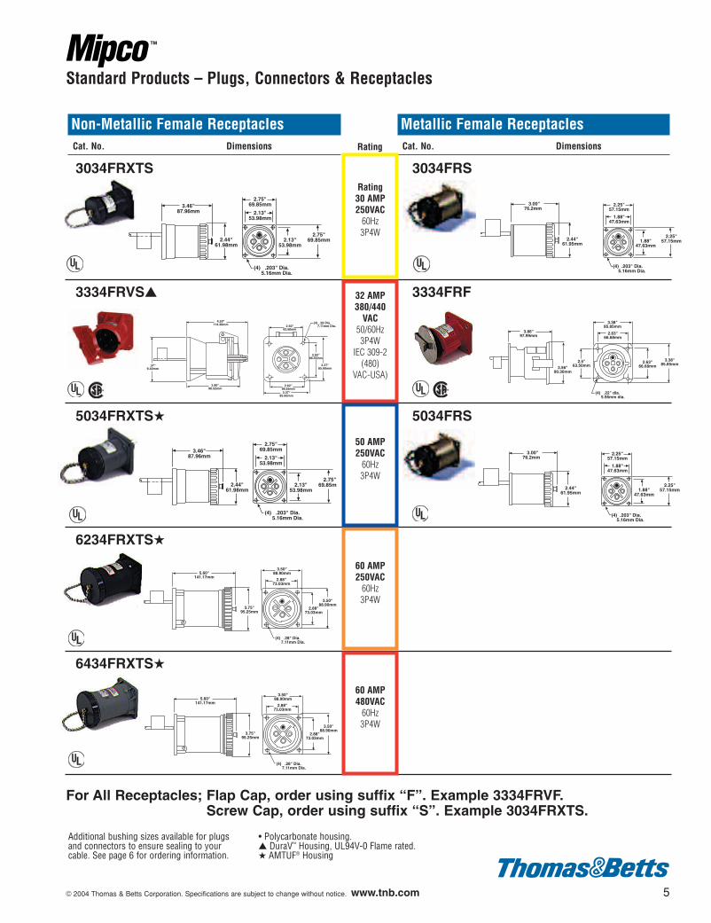
3034FRXTS
3334FRVS▲
5034FRXTS★
6234FRXTS★
6434FRXTS★
3034FRS
3334FRF
5034FRS
Non-Metallic Female ReceptaclesCat. No. Dimensions
Metallic Female ReceptaclesCat. No. Dimensions
Standard Products – Plugs, Connectors & Receptacles
3.46"87.96mm
2.44"61.98mm
2.75"69.85mm
2.13"53.98mm
2.13"53.98mm
2.75"69.85mm
(4) .203" Dia. 5.16mm Dia.
2.50"63.50mm
2.62"66.55mm
2.62"66.55mm
3.37"85.60mm
3.37"85.60mm
(4) .28 Dia. 7.11mm Dia.
4.50"114.30mm
3.80"96.52mm
.37"9.40mm
3.46"87.96mm
2.44"61.98mm
2.75"69.85mm
2.13"53.98mm
2.13"53.98mm
2.75"69.85mm
(4) .203" Dia. 5.16mm Dia.
5.60"141.17mm
3.75"95.25mm
3.50"88.90mm
2.88"73.03mm
2.88"73.03mm
3.50"88.90mm
(4) .28" Dia. 7.11mm Dia.
5.60"141.17mm
3.75"95.25mm
3.50"88.90mm
2.88"73.03mm
2.88"73.03mm
3.50"88.90mm
(4) .28" Dia. 7.11mm Dia.
3.86"97.99mm
3.56"90.30mm
3.38"85.85mm2.63"
66.68mm
(4) .22" dia. 5.56mm dia.
3.38"85.85mm
2.63"66.68mm
2.5"63.50mm
¤
¤¤
¤
¤
¤
¤¤
¤
¤
Additional bushing sizes available for plugsand connectors to ensure sealing to yourcable. See page 6 for ordering information.
• Polycarbonate housing.▲ DuraV™ Housing, UL94V-0 Flame rated.★ AMTUF® Housing
For All Receptacles; Flap Cap, order using suffix “F”. Example 3334FRVF.Screw Cap, order using suffix “S”. Example 3034FRXTS.
Rating30 AMP250VAC
60Hz3P4W
60 AMP250VAC
60Hz3P4W
50 AMP250VAC
60Hz3P4W
60 AMP480VAC
60Hz3P4W
32 AMP380/440
VAC50/60Hz3P4W
IEC 309-2(480)
VAC-USA)
3.00"76.2mm
2.44"61.95mm
2.25"57.15mm
1.88"47.63mm
1.88"47.63mm
2.25"57.15mm
(4) .203" Dia. 5.16mm Dia.
3.00"76.2mm
2.44"61.95mm
2.25"57.15mm
1.88"47.63mm
1.88"47.63mm
2.25"57.15mm
(4) .203" Dia. 5.16mm Dia.
Rating
602110.01_3-16 3/16/04 3:28 PM Page 5
6 © 2004 Thomas & Betts Corporation. Specifications are subject to change without notice. www.tnb.com
Standard Products – Plugs, Connectors & Receptacles
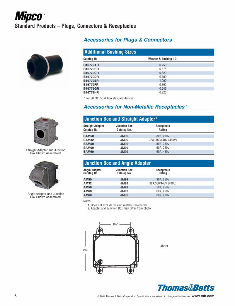
Accessories for Plugs & Connectors
Additional Bushing SizesCatalog No. Washer & Bushing I.D.
B16779AR 0.750B16779BR 0.875B16779CR 0.620B16779DR 0.700B16779ER 1.000B16779FR 0.800B16779GR 0.545B16779HR 0.925
* For 30, 32, 50 & 60A standard devices.
Accessories for Non-Metallic Receptacles 1
Junction Box and Straight Adapter 2
Straight Adapter Junction Box ReceptacleCatalog No. Catalog No. Rating
SAM50 JM99 30A, 250VSAM32 JM99 32A, 380/440V (480V)SAM50 JM99 50A, 250VSAM60 JM99 60A, 250VSAM60 JM99 60A, 480V
Junction Box and Angle AdapterAngle Adapter Junction Box ReceptacleCatalog No. Catalog No. Rating
AM50 JM99 30A, 250VAM32 JM99 32A,380/440V (480V)AM50 JM99 50A, 250VAM60 JM99 60A, 250VAM60 JM99 60A, 480V
Notes:1. Does not exclude 32 amp metallic receptacles2. Adapter and Junction Box may differ from photo
Straight Adapter and JunctionBox Shown Assembled.
Angle Adapter and JunctionBox Shown Assembled.
JM99
602110.01_3-16 3/16/04 3:28 PM Page 6
© 2004 Thomas & Betts Corporation. Specifications are subject to change without notice. www.tnb.com 7
30 AMP250VAC,
60Hz3P4W
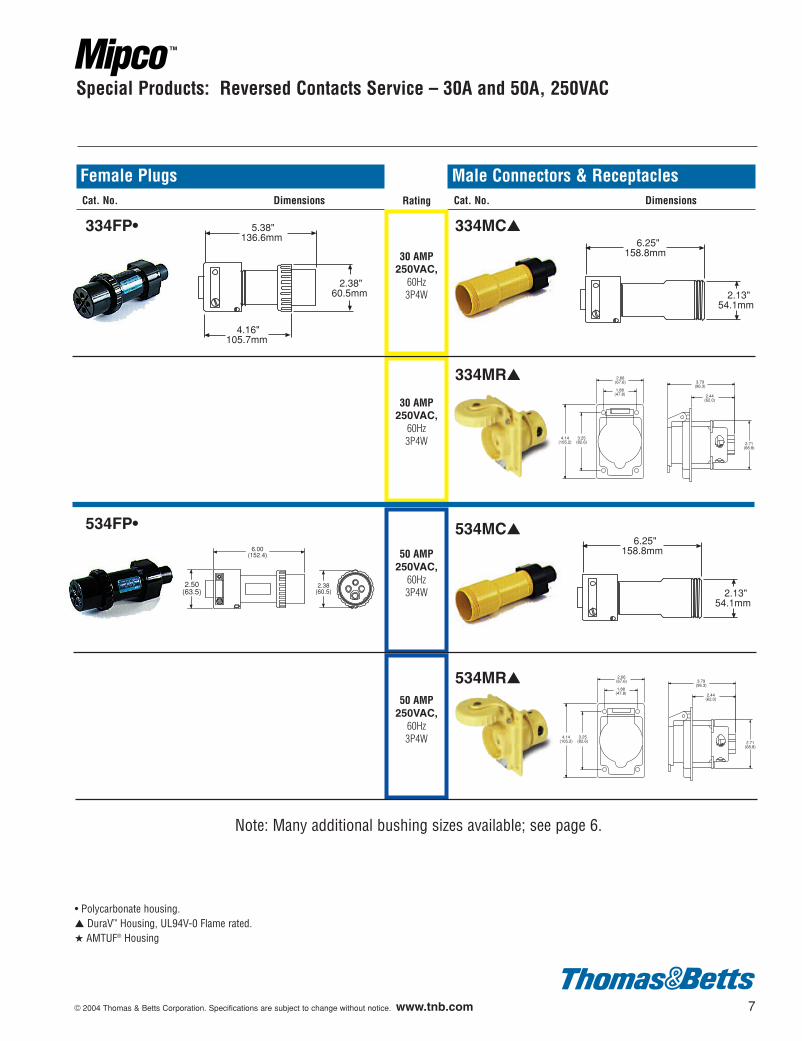
Special Products: Reversed Contacts Service – 30A and 50A, 250VAC
334FP•
534FP•
334MC▲
334MR▲
534MC▲
534MR▲
5.38"136.6mm
2.38"60.5mm
4.16"105.7mm
6.25"158.8mm
2.13"54.1mm
6.00(152.4)
2.50(63.5)
2.38(60.5)
6.25"158.8mm
2.13"54.1mm
Note: Many additional bushing sizes available; see page 6.
Female PlugsCat. No. Dimensions
Male Connectors & ReceptaclesCat. No. Dimensions
30 AMP250VAC,
60Hz3P4W
50 AMP250VAC,
60Hz3P4W
50 AMP250VAC,
60Hz3P4W
Rating
2.66(67.6)
2.71(68.8)
4.14(105.2)
3.79(96.3)
2.44(62.0)
3.25(82.6)
1.88(47.8)
2.66(67.6)
2.71(68.8)
4.14(105.2)
3.79(96.3)
2.44(62.0)
3.25(82.6)
1.88(47.8)
• Polycarbonate housing.▲ DuraV™ Housing, UL94V-0 Flame rated.★ AMTUF® Housing
602110.01_3-16 3/16/04 3:28 PM Page 7
8 © 2004 Thomas & Betts Corporation. Specifications are subject to change without notice. www.tnb.com
223MP2
334MP5
Australian
223FC2
334FC5
3.87"
2.16"
2.75"
4.75"120.7mm
1.88"47.8mm
Ordering Information: 20 Amp and Australian
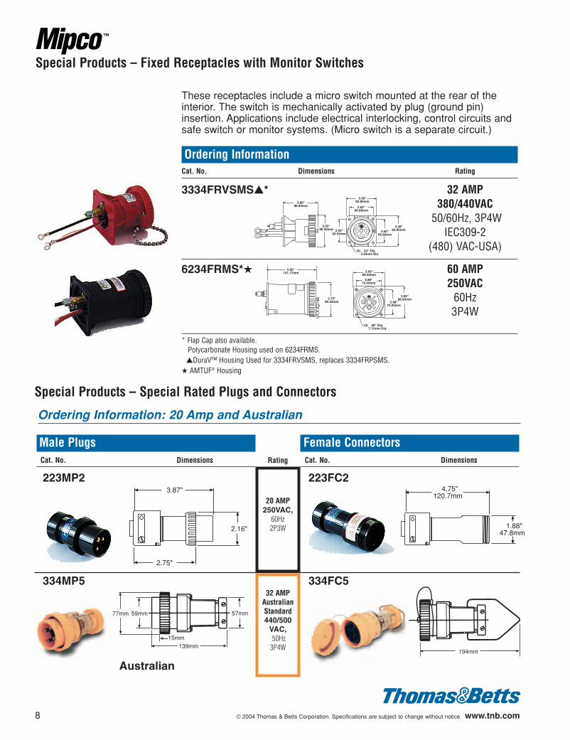
Special Products – Fixed Receptacles with Monitor Switches
These receptacles include a micro switch mounted at the rear of theinterior. The switch is mechanically activated by plug (ground pin)insertion. Applications include electrical interlocking, control circuits andsafe switch or monitor systems. (Micro switch is a separate circuit.)
Ordering InformationCat. No. Dimensions Rating
3334FRVSMS▲* 32 AMP380/440VAC
50/60Hz, 3P4WIEC309-2
(480) VAC-USA)
6234FRMS*★ 60 AMP250VAC
60Hz3P4W
* Flap Cap also available.Polycarbonate Housing used on 6234FRMS.▲DuraV™ Housing Used for 3334FRVSMS, replaces 3334FRPSMS.
★ AMTUF® Housing
3.89"96.63mm
3.55"90.30mm 2.50"
63.50mm
(4) .22" Dia. 5.54mm Dia.
2.63"66.68mm
2.63"66.68mm
3.38"85.85mm
3.38"85.85mm
Male PlugsCat. No. Dimensions
Female ConnectorsCat. No. Dimensions
20 AMP250VAC,
60Hz2P3W
32 AMPAustralianStandard440/500
VAC,50Hz
3P4W
Rating
Special Products – Special Rated Plugs and Connectors
3.50"88.90mm
2.88"73.03mm
2.88"73.03mm
3.50"88.90mm
(4) .28" Dia. 7.11mm Dia.
5.60"141.17mm
3.75"95.25mm
139mm15mm
57mm59mm77mm
194mm
602110.01_3-16 3/16/04 3:29 PM Page 8
© 2004 Thomas & Betts Corporation. Specifications are subject to change without notice. www.tnb.com 9
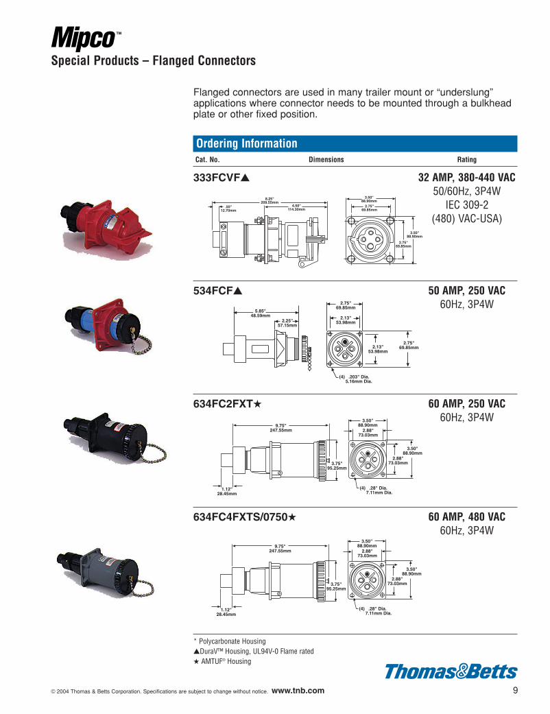
Flanged connectors are used in many trailer mount or “underslung”applications where connector needs to be mounted through a bulkheadplate or other fixed position.
Ordering InformationCat. No. Dimensions Rating
333FCVF▲ 32 AMP, 380-440 VAC50/60Hz, 3P4W
IEC 309-2(480) VAC-USA)
534FCF▲ 50 AMP, 250 VAC60Hz, 3P4W
634FC2FXT★ 60 AMP, 250 VAC60Hz, 3P4W
634FC4FXTS/0750★ 60 AMP, 480 VAC60Hz, 3P4W
* Polycarbonate Housing▲DuraV™ Housing, UL94V-0 Flame rated★ AMTUF® Housing
Special Products – Flanged Connectors
3.50"88.90mm
3.50"88.90mm
2.75"69.85mm
2.75"69.85mm
.50"12.70mm
8.25"209.55mm
4.50"114.30mm
2.75"69.85mm
2.13"53.98mm
2.13"53.98mm
2.75"69.85mm
(4) .203" Dia. 5.16mm Dia.
5.85"48.59mm
2.25"57.15mm
9.75"247.55mm
1.12"28.45mm
3.75"95.25mm
3.50"88.90mm
3.50"88.90mm
2.88"73.03mm
2.88"73.03mm
(4) .28" Dia. 7.11mm Dia.
9.75"247.55mm
1.12"28.45mm
3.75"95.25mm
3.50"88.90mm
3.50"88.90mm
2.88"73.03mm
2.88"73.03mm
(4) .28" Dia. 7.11mm Dia.
602110.01_3-16 3/16/04 3:29 PM Page 9
10 © 2004 Thomas & Betts Corporation. Specifications are subject to change without notice. www.tnb.com
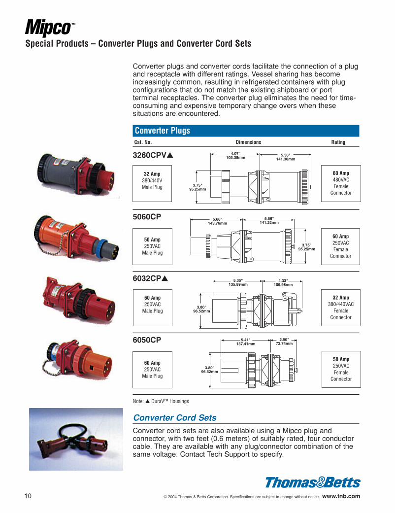
Converter plugs and converter cords facilitate the connection of a plugand receptacle with different ratings. Vessel sharing has becomeincreasingly common, resulting in refrigerated containers with plugconfigurations that do not match the existing shipboard or portterminal receptacles. The converter plug eliminates the need for time-consuming and expensive temporary change overs when thesesituations are encountered.
Converter PlugsCat. No. Dimensions Rating
3260CPV▲
5060CP
6032CP▲
6050CP
Converter Cord SetsConverter cord sets are also available using a Mipco plug andconnector, with two feet (0.6 meters) of suitably rated, four conductorcable. They are available with any plug/connector combination of thesame voltage. Contact Tech Support to specify.
Special Products – Converter Plugs and Converter Cord Sets
4.07"103.38mm
5.56"141.30mm
3.75"95.25mm
5.66"143.76mm
5.56"141.22mm
3.75"95.25mm
5.35"135.89mm
3.80"96.52mm
4.33"109.98mm
3.80"96.52mm
5.41"137.41mm
2.90"73.74mm
Note: ▲ DuraV™ Housings
60 Amp480VACFemale
Connector
60 Amp250VACFemale
Connector
32 Amp380/440VAC
Female Connector
50 Amp250VACFemale
Connector
32 Amp380/440VMale Plug
50 Amp250VAC
Male Plug
60 Amp250VAC
Male Plug
60 Amp250VAC
Male Plug
602110.01_3-16 3/16/04 3:29 PM Page 10
© 2004 Thomas & Betts Corporation. Specifications are subject to change without notice. www.tnb.com 11
Standard and Special Products – Plugs, Connectors & Receptacles
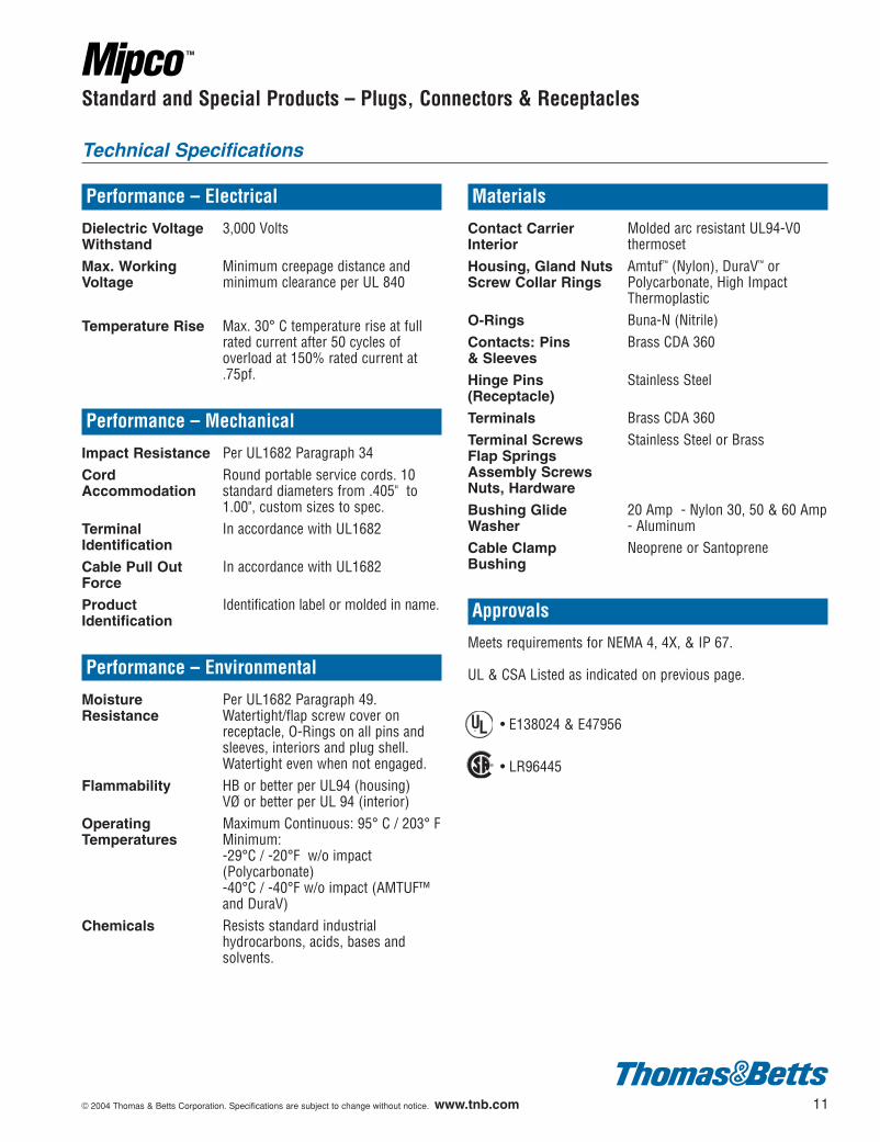
Performance – Electrical
Dielectric Voltage 3,000 VoltsWithstand
Max. Working Minimum creepage distance andVoltage minimum clearance per UL 840
Temperature Rise Max. 30° C temperature rise at fullrated current after 50 cycles ofoverload at 150% rated current at.75pf.
Performance – Mechanical
Impact Resistance Per UL1682 Paragraph 34Cord Round portable service cords. 10 Accommodation standard diameters from .405" to
1.00", custom sizes to spec.Terminal In accordance with UL1682Identification
Cable Pull Out In accordance with UL1682Force
Product Identification label or molded in name.Identification
Performance – Environmental
Moisture Per UL1682 Paragraph 49. Resistance Watertight/flap screw cover on
receptacle, O-Rings on all pins andsleeves, interiors and plug shell.Watertight even when not engaged.
Flammability HB or better per UL94 (housing)VØ or better per UL 94 (interior)
Operating Maximum Continuous: 95° C / 203° FTemperatures Minimum:
-29°C / -20°F w/o impact(Polycarbonate)-40°C / -40°F w/o impact (AMTUF™and DuraV)
Chemicals Resists standard industrialhydrocarbons, acids, bases andsolvents.
Materials
Contact Carrier Molded arc resistant UL94-V0Interior thermosetHousing, Gland Nuts Amtuf™ (Nylon), DuraV™ or Screw Collar Rings Polycarbonate, High Impact
ThermoplasticO-Rings Buna-N (Nitrile)Contacts: Pins Brass CDA 360& Sleeves
Hinge Pins Stainless Steel(Receptacle)
Terminals Brass CDA 360Terminal Screws Stainless Steel or BrassFlap SpringsAssembly ScrewsNuts, Hardware
Bushing Glide 20 Amp - Nylon 30, 50 & 60 AmpWasher - AluminumCable Clamp Neoprene or SantopreneBushing
Approvals
Meets requirements for NEMA 4, 4X, & IP 67.
UL & CSA Listed as indicated on previous page.
• E138024 & E47956
• LR96445
Technical Specifications
¤
¤
602110.01_3-16 3/16/04 3:29 PM Page 11
12 © 2004 Thomas & Betts Corporation. Specifications are subject to change without notice. www.tnb.com
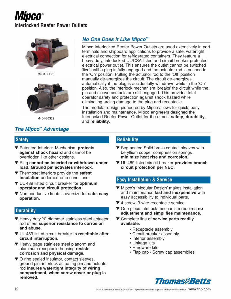
Interlocked Reefer Power Outlets
No One Does it Like Mipco™
Mipco Interlocked Reefer Power Outlets are used extensively in portterminals and shipboard applications to provide a safe, watertightelectrical connection for refrigerated containers. They feature aheavy duty, interlocked UL/CSA listed and circuit breaker protectedelectrical power outlet. This ensures the outlet cannot be switched‘live’ until a plug is fully engaged and the actuator rod is pushed tothe ‘On’ position. Pulling the actuator rod to the ‘Off’ positionmanually de-energizes the circuit. The circuit de-energizesautomatically if the plug is accidentally withdrawn while in the ‘On’position. Also, the interlock mechanism ‘breaks’ the circuit while thepin and sleeve contacts are still engaged. This provides totaloperator safety and protection against shock hazard whileeliminating arcing damage to the plug and receptacle.The modular design pioneered by Mipco allows for quick, easyinstallation and maintenance. Mipco engineers designed theInterlocked Reefer Power Outlet for the utmost safety, durability,and reliability.
Safety
▼ Patented Interlock Mechanism protectsagainst shock hazard and cannot beoverridden like other designs.
▼ Plug cannot be inserted or withdrawn underload. Ground pin activates interlock.
▼ Thermoset interiors provide the safestinsulation under extreme conditions.
▼ UL 489 listed circuit breaker for optimumoperator and circuit protection.
▼ Non-conductive knob is oversize for safe, easyoperation.
Durability
▼ Heavy duty d" diameter stainless steel actuatorrod offers superior resistance to corrosionand abuse.
▼ UL 489 listed circuit breaker is resettable aftercircuit interruption.
▼ Heavy gage stainless steel platform andaluminum receptacle housing resistscorrosion and physical damage.
▼ O-ring sealed insulator, contact sleeves,ground pin, interlock actuating pin and actuatorrod insures watertight integrity of wiringcompartment, when screw cover or plug isremoved.
Reliability
▼ Segmented Solid brass contact sleeves withberyllium copper compression springsminimize heat rise and corrosion.
▼ UL 489 listed circuit breaker provides branchcircuit protection per NEC.
Easy Installation & Service
▼ Mipco’s ‘Modular Design’ makes installationand maintenance fast and inexpensive witheasy accessibility to individual parts.
▼ 4 screw, 3 wire receptacle service.▼ One piece interlock mechanism requires no
adjustment and simplifies maintenance.▼ Complete line of service parts readily
available.• Receptacle assembly• Circuit breaker assembly• Interior assembly• Linkage kits• Hardware kits• Flap cap / Screw cap assemblies
The Mipco™ Advantage
M433-30F22
M464-30S22
602110.01_3-16 3/16/04 3:29 PM Page 12
© 2004 Thomas & Betts Corporation. Specifications are subject to change without notice. www.tnb.com 13
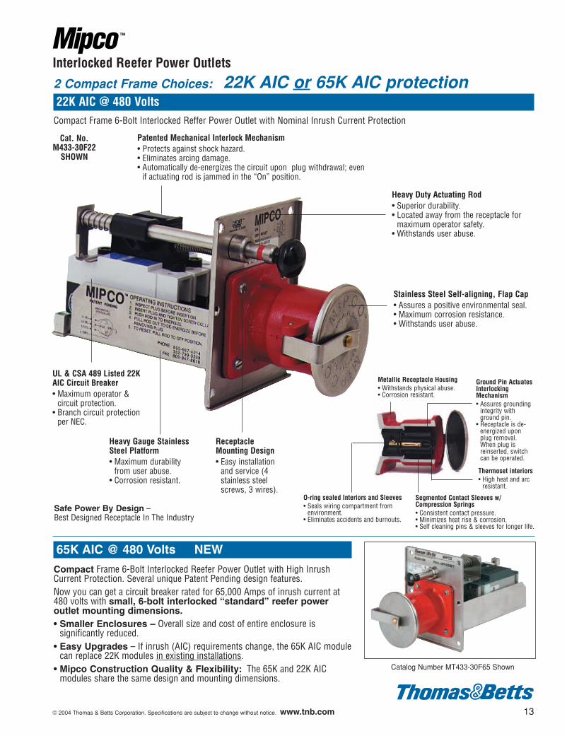
Interlocked Reefer Power Outlets
UL & CSA 489 Listed 22KAIC Circuit Breaker• Maximum operator &
circuit protection.• Branch circuit protection
per NEC.
Patented Mechanical Interlock Mechanism• Protects against shock hazard.• Eliminates arcing damage.• Automatically de-energizes the circuit upon plug withdrawal; even
if actuating rod is jammed in the “On” position.
Stainless Steel Self-aligning, Flap Cap • Assures a positive environmental seal.• Maximum corrosion resistance.• Withstands user abuse.
Metallic Receptacle Housing• Withstands physical abuse.• Corrosion resistant.
Thermoset interiors• High heat and arc
resistant.
Ground Pin ActuatesInterlockingMechanism• Assures grounding
integrity withground pin.
• Receptacle is de-energized uponplug removal.When plug isreinserted, switchcan be operated.
Segmented Contact Sleeves w/ Compression Springs• Consistent contact pressure.• Minimizes heat rise & corrosion.• Self cleaning pins & sleeves for longer life.
O-ring sealed Interiors and Sleeves• Seals wiring compartment from
environment.• Eliminates accidents and burnouts.
ReceptacleMounting Design• Easy installation
and service (4stainless steelscrews, 3 wires).
Heavy Gauge StainlessSteel Platform• Maximum durability
from user abuse.• Corrosion resistant.
Cat. No.M433-30F22
SHOWN
Safe Power By Design – Best Designed Receptacle In The Industry
65K AIC @ 480 Volts NEW
Compact Frame 6-Bolt Interlocked Reefer Power Outlet with High InrushCurrent Protection. Several unique Patent Pending design features.Now you can get a circuit breaker rated for 65,000 Amps of inrush current at480 volts with small, 6-bolt interlocked “standard” reefer poweroutlet mounting dimensions.• Smaller Enclosures – Overall size and cost of entire enclosure is
significantly reduced.• Easy Upgrades – If inrush (AIC) requirements change, the 65K AIC module
can replace 22K modules in existing installations.• Mipco Construction Quality & Flexibility: The 65K and 22K AIC
modules share the same design and mounting dimensions.
Heavy Duty Actuating Rod• Superior durability.• Located away from the receptacle for
maximum operator safety.• Withstands user abuse.
2 Compact Frame Choices: 22K AIC or 65K AIC protection22K AIC @ 480 Volts
Compact Frame 6-Bolt Interlocked Reffer Power Outlet with Nominal Inrush Current Protection
Catalog Number MT433-30F65 Shown
602110.01_3-16 3/16/04 3:29 PM Page 13
14 © 2004 Thomas & Betts Corporation. Specifications are subject to change without notice. www.tnb.com
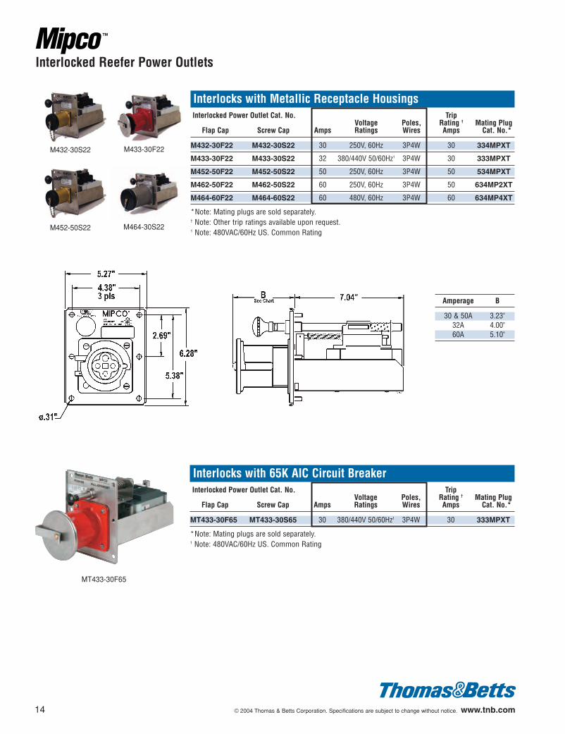
Interlocks with Metallic Receptacle HousingsInterlocked Power Outlet Cat. No. Trip
Voltage Poles, Rating † Mating PlugFlap Cap Screw Cap Amps Ratings Wires Amps Cat. No.*
M432-30F22 M432-30S22 30 250V, 60Hz 3P4W 30 334MPXT
M433-30F22 M433-30S22 32 380/440V 50/60Hz1 3P4W 30 333MPXT
M452-50F22 M452-50S22 50 250V, 60Hz 3P4W 50 534MPXT
M462-50F22 M462-50S22 60 250V, 60Hz 3P4W 50 634MP2XT
M464-60F22 M464-60S22 60 480V, 60Hz 3P4W 60 634MP4XT
*Note: Mating plugs are sold separately.† Note: Other trip ratings available upon request.1 Note: 480VAC/60Hz US. Common Rating
M432-30S22
M452-50S22
M433-30F22
M464-30S22
Amperage B
30 & 50A 3.23"32A 4.00"60A 5.10"
Interlocked Reefer Power Outlets
Interlocks with 65K AIC Circuit BreakerInterlocked Power Outlet Cat. No. Trip
Voltage Poles, Rating † Mating PlugFlap Cap Screw Cap Amps Ratings Wires Amps Cat. No.*
MT433-30F65 MT433-30S65 30 380/440V 50/60Hz1 3P4W 30 333MPXT
*Note: Mating plugs are sold separately.1 Note: 480VAC/60Hz US. Common Rating
MT433-30F65
602110.01_3-16 3/16/04 3:29 PM Page 14
© 2004 Thomas & Betts Corporation. Specifications are subject to change without notice. www.tnb.com 15
Interlocked Reefer Power Outlets
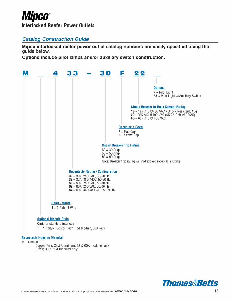
Catalog Construction GuideMipco interlocked reefer power outlet catalog numbers are easily specified using theguide below.Options include pilot lamps and/or auxiliary switch construction.
M 4 3 3 – 3 0 F 2 2
OptionsP = Pilot LightPA = Pilot Light w/Auxiliary Switch
Circuit Breaker In-Rush Current Rating18 = 18K AIC @480 VAC - Shock Resistant, 15g22 - 22K AIC @480 VAC (65K AIC @ 250 VAC)65 = 65K AIC @ 480 VAC
Receptacle CoverF = Flap CapS = Screw Cap
Circuit Breaker Trip Rating30 = 30 Amp50 = 50 Amp60 = 60 AmpNote: Breaker trip rating will not exceed receptacle rating
Receptacle Rating / Configuration32 = 30A, 250 VAC, 50/60 Hz33 = 32A, 380/440V, 50/60 Hz52 = 50A, 250 VAC, 50/60 Hz62 = 60A, 250 VAC, 50/60 Hz64 = 60A, 440/480 VAC, 50/60 Hz
Poles / Wires4 = 3 Pole, 4 Wire
Optional Module StyleOmit for standard interlockT = “T” Style, Center Push-Rod Module, 32A only
Receptacle Housing MaterialM = Metallic:
Copper Free, Cast Aluminum; 32 & 60A modules onlyBrass; 30 & 50A modules only
602110.01_3-16 3/16/04 3:29 PM Page 15
16 © 2004 Thomas & Betts Corporation. Specifications are subject to change without notice. www.tnb.com
Interlocked Reefer Power Outlets
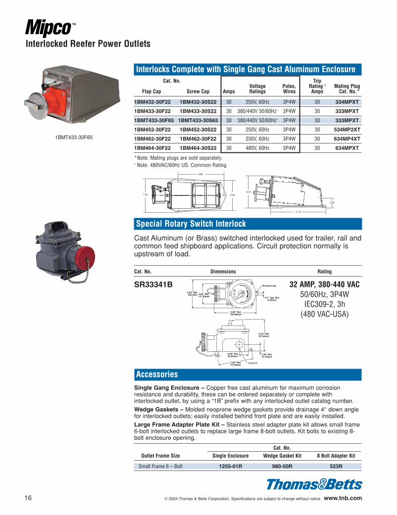
AccessoriesSingle Gang Enclosure – Copper free cast aluminum for maximum corrosionresistance and durability, these can be ordered separately or complete withinterlocked outlet, by using a “1B” prefix with any interlocked outlet catalog number.Wedge Gaskets – Molded neoprene wedge gaskets provide drainage 4° down anglefor interlocked outlets; easily installed behind front plate and are easily installed.Large Frame Adapter Plate Kit – Stainless steel adapter plate kit allows small frame6-bolt interlocked outlets to replace large frame 8-bolt outlets. Kit bolts to existing 8-bolt enclosure opening.
1BMT433-30F65
Special Rotary Switch Interlock
Cast Aluminum (or Brass) switched interlocked used for trailer, rail andcommon feed shipboard applications. Circuit protection normally isupstream of load.
Cat. No. Dimensions Rating
SR33341B 32 AMP, 380-440 VAC50/60Hz, 3P4WIEC309-2, 3h
(480 VAC-USA)
Ground Lug
.37" Typ. Ref.9.40mm
9.60" Ref.243.80mm
6.43" Ref.163.30m 4.62" Ref.
117.30mm
3.44" Ref.87.40mm
1.25" Ref.31.70mm
.75 N.P.T.7.00" Ref177.80mm
2.00" Ref50.80mm
Interlocks Complete with Single Gang Cast Aluminum EnclosureCat. No. Trip
Voltage Poles, Rating † Mating PlugFlap Cap Screw Cap Amps Ratings Wires Amps Cat. No.*
1BM432-30F22 1BM432-30S22 30 250V, 60Hz 3P4W 30 334MPXT
1BM433-30F22 1BM433-30S22 30 380/440V 50/60Hz1 3P4W 30 333MPXT
1BMT433-30F65 1BMT433-30S65 30 380/440V 50/60Hz1 3P4W 30 333MPXT
1BM452-30F22 1BM452-30S22 30 250V, 60Hz 3P4W 30 534MP2XT
1BM462-30F22 1BM462-30F22 30 250V, 60Hz 3P4W 30 634MP4XT
1BM464-30F22 1BM464-30S22 30 480V, 60Hz 3P4W 30 634MPXT
*Note: Mating plugs are sold separately.1 Note: 480VAC/60Hz US. Common Rating
7.00
9.38
6.256.75
11.75
2.00
Cat. No.Outlet Frame Size Single Enclosure Wedge Gasket Kit 8 Bolt Adapter Kit
Small Frame 6 – Bolt 1255-01R 980-50R 523R
602110.01_3-16 3/16/04 3:29 PM Page 16
© 2004 Thomas & Betts Corporation. Specifications are subject to change without notice. www.tnb.com 17
Interlocked Reefer Power Outlets
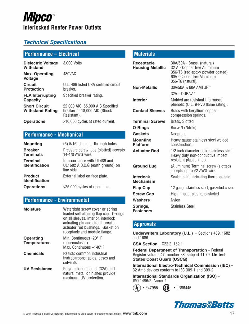
Performance – Electrical
Dielectric Voltage 3,000 VoltsWithstand
Max. Operating 480VACVoltage
Circuit U.L. 489 listed CSA certified circuit Protection breaker.FLA Interrupting Specified breaker rating.Capacity
Short Circuit 22,000 AIC, 65,000 AIC SpecifiedWithstand Rating breaker or 18,000 AIC (Shock
Resistant).Operations >10,000 cycles at rated current.
Performance - Mechanical
Mounting (6) 5/16" diameter through holes.Breaker Pressure screw lugs (slotted) acceptsTerminals 14-1/0 AWG wire.Terminal In accordance with UL489 andIdentification UL1682 A,B,C,G (earth ground) on
line side.Product External label on face plate.Identification
Operations >25,000 cycles of operation.
Performance - Environmental
Moisture Watertight screw cover or springloaded self aligning flap cap. O-ringson all sleeves, interior, interlockactuating pin and circuit breakeractuator rod bushings. Gasket onreceptacle and module flange.
Operating Min. Continuous -20º F Temperatures (non-enclosed)
Max. Continuous +140º FChemicals Resists common industrial
hydrocarbons, acids, bases andsolvents.
UV Resistance Polyurethane enamel (32A) andnatural metallic finishes providemaximum UV protection.
Materials
Receptacle 30A/50A - Brass (natural)Housing Metallic 32 A - Copper free Aluminum
356-T6 (red epoxy powder coated)60A - Copper free Aluminum 356-T6 (natural).
Non-Metallic 30A/50A & 60A AMTUF ™
32A – DURAV ™
Interior Molded arc resistant thermosetphenolic (U.L. 94-V0 flame rating).
Contact Sleeves Brass with beryllium coppercompression springs.
Terminal Screws Brass, Slotted O-Rings Buna-N (Nitrile)Gaskets NeopreneMounting Heavy gauge stainless steel weldedPlatform construction.Actuator Rod 1/2 inch diameter solid stainless steel.
Heavy duty non-conductive impactresistant plastic knob.
Ground Lug (Aluminum) Terminal screw (slotted)accepts up to #2 AWG wire.
Interlock Sealed self lubricating thermoplastic.Mechanism
Flap Cap 12 gauge stainless steel, gasketed cover.Screw Cap High impact plastic, gasketedWashers NylonSprings, Stainless SteelFasteners
Approvals
Underwriters Laboratory (U.L.) – Sections 489, 1682 and 1686.CSA Section – C22.2–182.1Federal Department of Transportation – FederalRegister volume 47, number 68, subpart 11.79 UnitedStates Coast Guard (USCG)
International Electro-Technical Commission (IEC) –32 Amp devices conform to IEC 309-1 and 309-2International Standards Organization (ISO) – ISO 1496/2, Annex 1
• E47955 • LR96445¤¤
Technical Specifications
602110.01_3-16 3/16/04 3:29 PM Page 17
18 © 2004 Thomas & Betts Corporation. Specifications are subject to change without notice. www.tnb.com
Interlocked Reefer Power Outlets
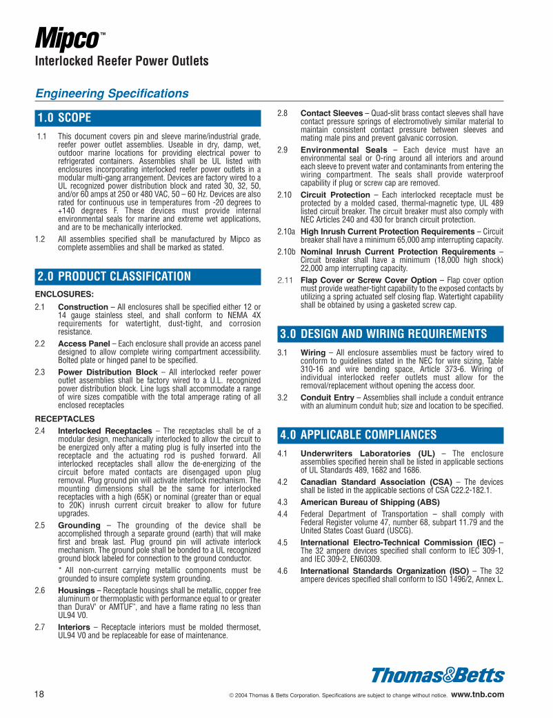
1.0 SCOPE1.1 This document covers pin and sleeve marine/industrial grade,
reefer power outlet assemblies. Useable in dry, damp, wet,outdoor marine locations for providing electrical power torefrigerated containers. Assemblies shall be UL listed withenclosures incorporating interlocked reefer power outlets in amodular multi-gang arrangement. Devices are factory wired to aUL recognized power distribution block and rated 30, 32, 50,and/or 60 amps at 250 or 480 VAC, 50 – 60 Hz. Devices are alsorated for continuous use in temperatures from -20 degrees to+140 degrees F. These devices must provide internalenvironmental seals for marine and extreme wet applications,and are to be mechanically interlocked.
1.2 All assemblies specified shall be manufactured by Mipco ascomplete assemblies and shall be marked as stated.
2.0 PRODUCT CLASSIFICATIONENCLOSURES:
2.1 Construction – All enclosures shall be specified either 12 or14 gauge stainless steel, and shall conform to NEMA 4Xrequirements for watertight, dust-tight, and corrosionresistance.
2.2 Access Panel – Each enclosure shall provide an access paneldesigned to allow complete wiring compartment accessibility.Bolted plate or hinged panel to be specified.
2.3 Power Distribution Block – All interlocked reefer poweroutlet assemblies shall be factory wired to a U.L. recognizedpower distribution block. Line lugs shall accommodate a rangeof wire sizes compatible with the total amperage rating of allenclosed receptacles
RECEPTACLES2.4 Interlocked Receptacles – The receptacles shall be of a
modular design, mechanically interlocked to allow the circuit tobe energized only after a mating plug is fully inserted into thereceptacle and the actuating rod is pushed forward. Allinterlocked receptacles shall allow the de-energizing of thecircuit before mated contacts are disengaged upon plugremoval. Plug ground pin will activate interlock mechanism. Themounting dimensions shall be the same for interlockedreceptacles with a high (65K) or nominal (greater than or equalto 20K) inrush current circuit breaker to allow for futureupgrades.
2.5 Grounding – The grounding of the device shall beaccomplished through a separate ground (earth) that will makefirst and break last. Plug ground pin will activate interlockmechanism. The ground pole shall be bonded to a UL recognizedground block labeled for connection to the ground conductor. * All non-current carrying metallic components must begrounded to insure complete system grounding.
2.6 Housings – Receptacle housings shall be metallic, copper freealuminum or thermoplastic with performance equal to or greaterthan DuraV’ or AMTUF™, and have a flame rating no less thanUL94 V0.
2.7 Interiors – Receptacle interiors must be molded thermoset,UL94 V0 and be replaceable for ease of maintenance.
2.8 Contact Sleeves – Quad-slit brass contact sleeves shall havecontact pressure springs of electromotively similar material tomaintain consistent contact pressure between sleeves andmating male pins and prevent galvanic corrosion.
2.9 Environmental Seals – Each device must have anenvironmental seal or O-ring around all interiors and aroundeach sleeve to prevent water and contaminants from entering thewiring compartment. The seals shall provide waterproofcapability if plug or screw cap are removed.
2.10 Circuit Protection – Each interlocked receptacle must beprotected by a molded cased, thermal-magnetic type, UL 489listed circuit breaker. The circuit breaker must also comply withNEC Articles 240 and 430 for branch circuit protection.
2.10a High Inrush Current Protection Requirements – Circuitbreaker shall have a minimum 65,000 amp interrupting capacity.
2.10b Nominal Inrush Current Protection Requirements –Circuit breaker shall have a minimum (18,000 high shock)22,000 amp interrupting capacity.
2.11 Flap Cover or Screw Cover Option – Flap cover optionmust provide weather-tight capability to the exposed contacts byutilizing a spring actuated self closing flap. Watertight capabilityshall be obtained by using a gasketed screw cap.
3.0 DESIGN AND WIRING REQUIREMENTS3.1 Wiring – All enclosure assemblies must be factory wired to
conform to guidelines stated in the NEC for wire sizing, Table310-16 and wire bending space, Article 373-6. Wiring ofindividual interlocked reefer outlets must allow for theremoval/replacement without opening the access door.
3.2 Conduit Entry – Assemblies shall include a conduit entrancewith an aluminum conduit hub; size and location to be specified.
4.0 APPLICABLE COMPLIANCES4.1 Underwriters Laboratories (UL) – The enclosure
assemblies specified herein shall be listed in applicable sectionsof UL Standards 489, 1682 and 1686.
4.2 Canadian Standard Association (CSA) – The devicesshall be listed in the applicable sections of CSA C22.2-182.1.
4.3 American Bureau of Shipping (ABS)4.4 Federal Department of Transportation – shall comply with
Federal Register volume 47, number 68, subpart 11.79 and theUnited States Coast Guard (USCG).
4.5 International Electro-Technical Commission (IEC) –The 32 ampere devices specified shall conform to IEC 309-1,and IEC 309-2, EN60309.
4.6 International Standards Organization (ISO) – The 32ampere devices specified shall conform to ISO 1496/2, Annex L.
Engineering Specifications
602110.01_3-16 3/16/04 3:29 PM Page 18
© 2004 Thomas & Betts Corporation. Specifications are subject to change without notice. www.tnb.com 19
Multi-Gang Enclosure Systems
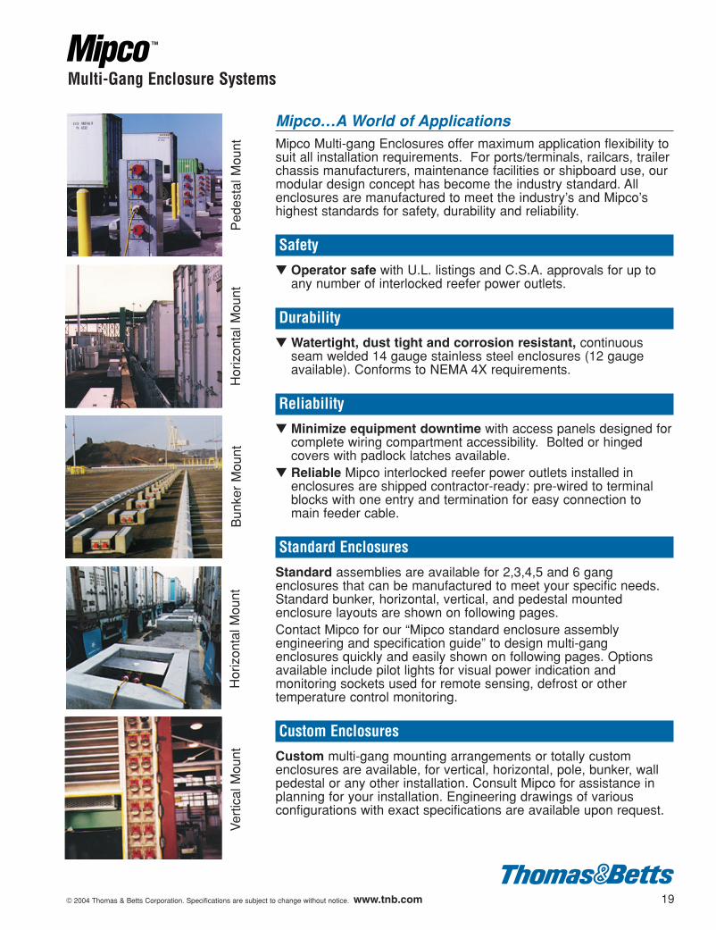
Mipco…A World of ApplicationsMipco Multi-gang Enclosures offer maximum application flexibility tosuit all installation requirements. For ports/terminals, railcars, trailerchassis manufacturers, maintenance facilities or shipboard use, ourmodular design concept has become the industry standard. Allenclosures are manufactured to meet the industry’s and Mipco’shighest standards for safety, durability and reliability.
Safety
▼ Operator safe with U.L. listings and C.S.A. approvals for up toany number of interlocked reefer power outlets.
Durability
▼ Watertight, dust tight and corrosion resistant, continuousseam welded 14 gauge stainless steel enclosures (12 gaugeavailable). Conforms to NEMA 4X requirements.
Reliability
▼ Minimize equipment downtime with access panels designed forcomplete wiring compartment accessibility. Bolted or hingedcovers with padlock latches available.
▼ Reliable Mipco interlocked reefer power outlets installed inenclosures are shipped contractor-ready: pre-wired to terminalblocks with one entry and termination for easy connection tomain feeder cable.
Standard Enclosures
Standard assemblies are available for 2,3,4,5 and 6 gangenclosures that can be manufactured to meet your specific needs.Standard bunker, horizontal, vertical, and pedestal mountedenclosure layouts are shown on following pages.Contact Mipco for our “Mipco standard enclosure assemblyengineering and specification guide” to design multi-gangenclosures quickly and easily shown on following pages. Optionsavailable include pilot lights for visual power indication andmonitoring sockets used for remote sensing, defrost or othertemperature control monitoring.
Custom Enclosures
Custom multi-gang mounting arrangements or totally customenclosures are available, for vertical, horizontal, pole, bunker, wallpedestal or any other installation. Consult Mipco for assistance inplanning for your installation. Engineering drawings of variousconfigurations with exact specifications are available upon request.
Ped
esta
l Mou
ntH
oriz
onta
l Mou
ntV
ertic
al M
ount
Bun
ker
Mou
ntH
oriz
onta
l Mou
nt
602110.01_3-16 3/16/04 3:29 PM Page 19
20 © 2004 Thomas & Betts Corporation. Specifications are subject to change without notice. www.tnb.com
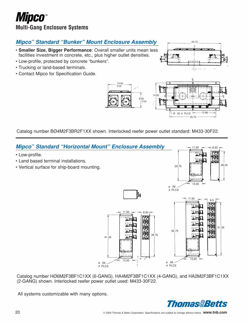
Catalog number HØ6M2F3BF1C1XX (6-GANG), HA4M2F3BF1C1XX (4-GANG), and HA2M2F3BF1C1XX(2-GANG) shown. Interlocked reefer power outlet used: M433-30F22.
Multi-Gang Enclosure Systems
Mipco™ Standard “Bunker” Mount Enclosure Assembly• Smaller Size, Bigger Performance: Overall smaller units mean less
facilities investment in concrete, etc., plus higher outlet densities.• Low-profile, protected by concrete “bunkers”.• Trucking or land-based terminals.• Contact Mipco for Specification Guide.
Catalog number BØ4M2F3BR2F1XX shown. Interlocked reefer power outlet standard: M433-30F22.
CL
CL
Ø .56 6 PLCS 12.88
25.75
14.50
Mipco™ Standard “Horizontal Mount” Enclosure Assembly• Low-profile. • Land based terminal installations. • Vertical surface for ship-board mounting.
39.75
13.00
8.5011.50
41.25
ø .56 4 PLCS
29.75CL
13.00TYP
8.50 TYP
11.50
52.7551.25
8.5
13.00ø .56 4 PLCS
11.50 8.50
28.25
ø .564 PLCS
13.00
29.75
All systems customizable with many options.
602110.01_3-16 3/16/04 3:29 PM Page 20
© 2004 Thomas & Betts Corporation. Specifications are subject to change without notice. www.tnb.com 21
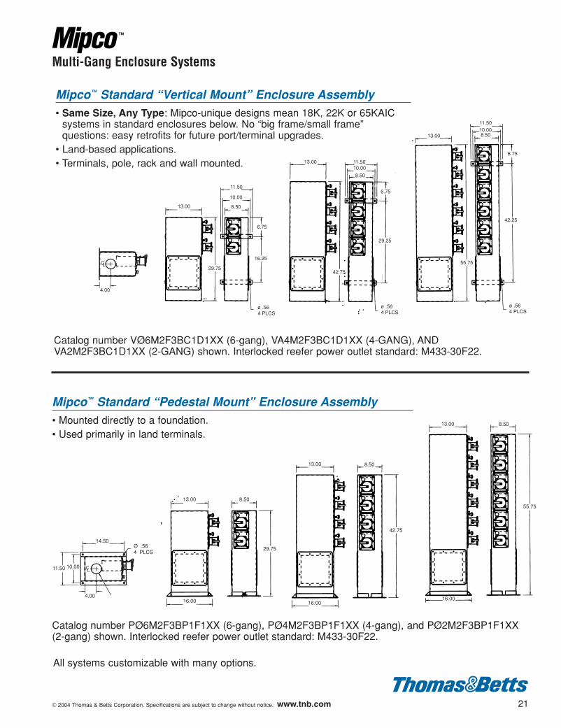
Multi-Gang Enclosure Systems
Mipco™ Standard “Vertical Mount” Enclosure Assembly• Same Size, Any Type: Mipco-unique designs mean 18K, 22K or 65KAIC
systems in standard enclosures below. No “big frame/small frame”questions: easy retrofits for future port/terminal upgrades.
• Land-based applications.• Terminals, pole, rack and wall mounted.
Catalog number VØ6M2F3BC1D1XX (6-gang), VA4M2F3BC1D1XX (4-GANG), ANDVA2M2F3BC1D1XX (2-GANG) shown. Interlocked reefer power outlet standard: M433-30F22.
13.00
8.50
10.0011.50
6.75
29.25
42.75
ø .564 PLCS
13.00
11.50
10.00
8.50
6.75
16.25
ø .564 PLCS
29.75
13.00 8.5010.0011.50
6.75
42.25
ø .564 PLCS
55.75
Mipco™ Standard “Pedestal Mount” Enclosure Assembly• Mounted directly to a foundation.• Used primarily in land terminals.
Catalog number PØ6M2F3BP1F1XX (6-gang), PØ4M2F3BP1F1XX (4-gang), and PØ2M2F3BP1F1XX(2-gang) shown. Interlocked reefer power outlet standard: M433-30F22.
13.00 8.50
55.75
16.0016.00
13.00 8.50
42.75
13.00 8.50
29.75
16.00
4.00
LC
Ø .56 4 PLCS
11.50 10.00
14.50
4.00
CL
All systems customizable with many options.
602110.01_3-16 3/16/04 3:29 PM Page 21
22 © 2004 Thomas & Betts Corporation. Specifications are subject to change without notice. www.tnb.com
Alternating Power Outlet (APO)
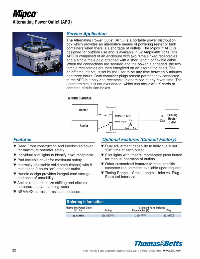
Service ApplicationThe Alternating Power Outlet (APO) is a portable power distributionbox which provides an alternative means of powering reefer or tankcontainers when there is a shortage of outlets. The Mipco™ APO isdesigned for outdoor use and is available in 32 Amps/480 Volts. TheAPO is comprised of an enclosure with two female fixed receptaclesand a single male plug attached with a short length of flexible cable.When the connections are secured and the power is engaged, the twofemale receptacles are then energized on an alternating basis. Theon/off time interval is set by the user to be any time between 5 minutesand three hours. Both container plugs remain permanently connectedto the APO but only one receptacle is energized at any given time. Theupstream circuit is not overloaded, which can occur with Y-cords orcommon distribution boxes.
WIRING DIAGRAM:
Reefer
Reefer
MIPCO™ APO
“On/Off” Adjust2 hr
3 hr5 min
Receptacle
Receptacle
ExistingReeferOutlet
Plug
Ordering InformationAlternating Power Outlet Standard Parts Included
Cat. No. Rating Receptacles (2) Plug
3334APO 32A/480VAC 3334FRVF 333MPXT
Features▼ Dead Front construction and interlocked cover
for maximum operator safety.▼ Individual pilot lights to identify “live” receptacle.▼ Pad-lockable cover for maximum safety. ▼ Internally adjustable solid-state timer(s) with 5
minutes to 3 hours “on” time per outlet.▼ Handle design provides integral cord storage
and ease of portability.▼ Anti-skid feet minimize shifting and elevate
enclosure above standing water.▼ NEMA 4X corrosion resistant enclosure.
Optional Features (Consult Factory)▼ Dual adjustment capability to individually set
“On” time of each outlet.▼ Pilot lights with integral momentary push button
for manual operation of outlets.▼ Other customized features to meet specific
customer requirements available upon request:▼ Timing Range – Cable Length – Inlet vs. Plug –
Electrical Interface
602110.01_3-16 3/16/04 3:29 PM Page 22
© 2004 Thomas & Betts Corporation. Specifications are subject to change without notice. www.tnb.com 23
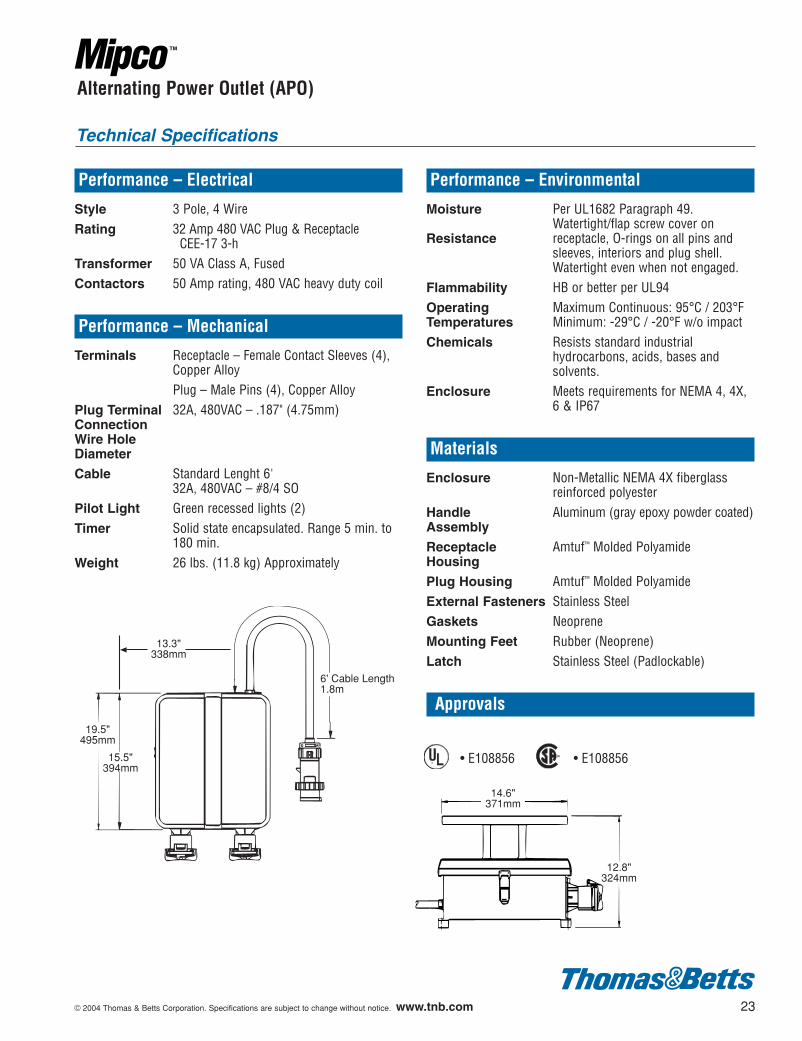
Alternating Power Outlet (APO)
Performance – Electrical
Style 3 Pole, 4 WireRating 32 Amp 480 VAC Plug & Receptacle
CEE-17 3-h Transformer 50 VA Class A, FusedContactors 50 Amp rating, 480 VAC heavy duty coil
Performance – Mechanical
Terminals Receptacle – Female Contact Sleeves (4),Copper AlloyPlug – Male Pins (4), Copper Alloy
Plug Terminal 32A, 480VAC – .187" (4.75mm)ConnectionWire Hole Diameter
Cable Standard Lenght 6'32A, 480VAC – #8/4 SO
Pilot Light Green recessed lights (2)Timer Solid state encapsulated. Range 5 min. to
180 min.Weight 26 lbs. (11.8 kg) Approximately
Performance – Environmental
Moisture Per UL1682 Paragraph 49. Watertight/flap screw cover on
Resistance receptacle, O-rings on all pins andsleeves, interiors and plug shell.Watertight even when not engaged.
Flammability HB or better per UL94Operating Maximum Continuous: 95°C / 203°FTemperatures Minimum: -29°C / -20°F w/o impactChemicals Resists standard industrial
hydrocarbons, acids, bases andsolvents.
Enclosure Meets requirements for NEMA 4, 4X, 6 & IP67
Materials
Enclosure Non-Metallic NEMA 4X fiberglassreinforced polyester
Handle Aluminum (gray epoxy powder coated)Assembly
Receptacle Amtuf™ Molded PolyamideHousing
Plug Housing Amtuf™ Molded PolyamideExternal Fasteners Stainless SteelGaskets NeopreneMounting Feet Rubber (Neoprene)Latch Stainless Steel (Padlockable)
Approvals
• E108856 • E108856¤¤
Technical Specifications
19.5"495mm
15.5"394mm
13.3"338mm
6' Cable Length1.8m
14.6"371mm
12.8"324mm
602110.01_3-16 3/16/04 3:29 PM Page 23
24 © 2004 Thomas & Betts Corporation. Specifications are subject to change without notice. www.tnb.com
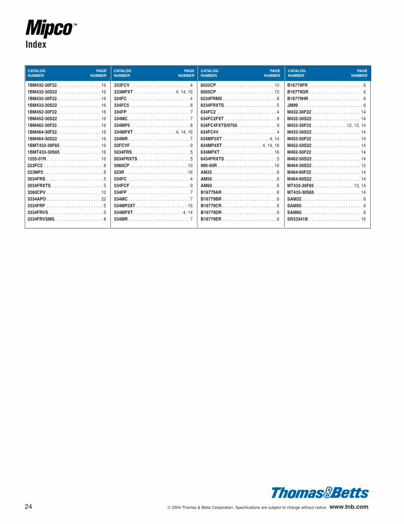
Index
CATALOG PAGENUMBER NUMBER
CATALOG PAGENUMBER NUMBER
CATALOG PAGENUMBER NUMBER
CATALOG PAGENUMBER NUMBER
1BM432-30F22. . . . . . . . . . . . . . . . . . 161BM432-30S22 . . . . . . . . . . . . . . . . . 161BM433-30F22. . . . . . . . . . . . . . . . . . 161BM433-30S22 . . . . . . . . . . . . . . . . . 161BM452-30F22. . . . . . . . . . . . . . . . . . 161BM452-30S22 . . . . . . . . . . . . . . . . . 161BM462-30F22. . . . . . . . . . . . . . . . . . 161BM464-30F22. . . . . . . . . . . . . . . . . . 161BM464-30S22 . . . . . . . . . . . . . . . . . 161BMT433-30F65. . . . . . . . . . . . . . . . . 161BMT433-30S65 . . . . . . . . . . . . . . . . 161255-01R . . . . . . . . . . . . . . . . . . . . . . 16223FC2 . . . . . . . . . . . . . . . . . . . . . . . . 8223MP2 . . . . . . . . . . . . . . . . . . . . . . . . 83034FRS . . . . . . . . . . . . . . . . . . . . . . . 53034FRXTS . . . . . . . . . . . . . . . . . . . . . 53260CPV . . . . . . . . . . . . . . . . . . . . . . 103334APO . . . . . . . . . . . . . . . . . . . . . . 223334FRF . . . . . . . . . . . . . . . . . . . . . . . 53334FRVS . . . . . . . . . . . . . . . . . . . . . . 53334FRVSMS. . . . . . . . . . . . . . . . . . . . 8
333FCV . . . . . . . . . . . . . . . . . . . . . . . . 4333MPXT . . . . . . . . . . . . . . . . . 4, 14, 16334FC . . . . . . . . . . . . . . . . . . . . . . . . . 4334FC5 . . . . . . . . . . . . . . . . . . . . . . . . 8334FP . . . . . . . . . . . . . . . . . . . . . . . . . 7334MC . . . . . . . . . . . . . . . . . . . . . . . . . 7334MP5 . . . . . . . . . . . . . . . . . . . . . . . . 8334MPXT . . . . . . . . . . . . . . . . . 4, 14, 16334MR . . . . . . . . . . . . . . . . . . . . . . . . . 733FCVF . . . . . . . . . . . . . . . . . . . . . . . . 95034FRS . . . . . . . . . . . . . . . . . . . . . . . 55034FRXTS . . . . . . . . . . . . . . . . . . . . . 55060CP . . . . . . . . . . . . . . . . . . . . . . . 10523R . . . . . . . . . . . . . . . . . . . . . . . . . 16534FC . . . . . . . . . . . . . . . . . . . . . . . . . 4534FCF . . . . . . . . . . . . . . . . . . . . . . . . 9534FP . . . . . . . . . . . . . . . . . . . . . . . . . 7534MC . . . . . . . . . . . . . . . . . . . . . . . . . 7534MP2XT . . . . . . . . . . . . . . . . . . . . . 16534MPXT . . . . . . . . . . . . . . . . . . . . 4, 14534MR . . . . . . . . . . . . . . . . . . . . . . . . . 7
6032CP . . . . . . . . . . . . . . . . . . . . . . . 106050CP . . . . . . . . . . . . . . . . . . . . . . . 106234FRMS . . . . . . . . . . . . . . . . . . . . . . 86234FRXTS . . . . . . . . . . . . . . . . . . . . . 5634FC2 . . . . . . . . . . . . . . . . . . . . . . . . 4634FC2FXT . . . . . . . . . . . . . . . . . . . . . 9634FC4FXTS/0750 . . . . . . . . . . . . . . . . 9634FC4V . . . . . . . . . . . . . . . . . . . . . . . 4634MP2XT . . . . . . . . . . . . . . . . . . . 4, 14634MP4XT . . . . . . . . . . . . . . . . 4, 14, 16634MPXT . . . . . . . . . . . . . . . . . . . . . . 166434FRXTS . . . . . . . . . . . . . . . . . . . . . 5980-50R . . . . . . . . . . . . . . . . . . . . . . . 16AM32 . . . . . . . . . . . . . . . . . . . . . . . . . . 6AM50 . . . . . . . . . . . . . . . . . . . . . . . . . . 6AM60 . . . . . . . . . . . . . . . . . . . . . . . . . . 6B16779AR . . . . . . . . . . . . . . . . . . . . . . 6B16779BR . . . . . . . . . . . . . . . . . . . . . . 6B16779CR . . . . . . . . . . . . . . . . . . . . . . 6B16779DR . . . . . . . . . . . . . . . . . . . . . . 6B16779ER . . . . . . . . . . . . . . . . . . . . . . 6
B16779FR . . . . . . . . . . . . . . . . . . . . . . 6B16779GR . . . . . . . . . . . . . . . . . . . . . . 6B16779HR . . . . . . . . . . . . . . . . . . . . . . 6JM99 . . . . . . . . . . . . . . . . . . . . . . . . . . 6M432-30F22 . . . . . . . . . . . . . . . . . . . . 14M432-30S22 . . . . . . . . . . . . . . . . . . . . 14M433-30F22 . . . . . . . . . . . . . . 12, 13, 14M433-30S22 . . . . . . . . . . . . . . . . . . . . 14M452-50F22 . . . . . . . . . . . . . . . . . . . . 14M452-50S22 . . . . . . . . . . . . . . . . . . . . 14M462-50F22 . . . . . . . . . . . . . . . . . . . . 14M462-50S22 . . . . . . . . . . . . . . . . . . . . 14M464-30S22 . . . . . . . . . . . . . . . . . . . . 12M464-60F22 . . . . . . . . . . . . . . . . . . . . 14M464-60S22 . . . . . . . . . . . . . . . . . . . . 14MT433-30F65 . . . . . . . . . . . . . . . . 13, 14MT433-30S65. . . . . . . . . . . . . . . . . . . 14SAM32 . . . . . . . . . . . . . . . . . . . . . . . . . 6SAM50 . . . . . . . . . . . . . . . . . . . . . . . . . 6SAM60 . . . . . . . . . . . . . . . . . . . . . . . . . 6SR33341B . . . . . . . . . . . . . . . . . . . . . 16
602110.01_3-16 3/16/04 3:29 PM Page 24
jva
blw

Plugs, Connectors &Receptacles for the
Refrigerated ContainerIndustry
Effective February 2004
Thomas & Betts CorporationElectrical Division8155 T&B BoulevardMemphis, Tennessee 38125
Thomas & Betts Ltd.700 Thomas AvenueIberville, Québec J2X 2M9
For U.S. Customer Service and Order Inquiries, call 1-800-816-7809 or fax 1-800-816-7810.For International Service and Order Inquiries, call (U.S.) 901-252-5400 or fax 901-252-1330.For Canadian Customer Service and Order Inquiries, call 450-347-5318 or fax 450-347-1976.
For U.S. Technical Support, call 1-888-862-3289 or fax 901-252-1321.For International Technical Support, call (U.S.) 901-252-5000, enter 1, 6672.For tool service and repair, call 1-800-284-TOOL (8665).
Call 1-800-858-6022 for our toll-free 24-hour Fax-On-Demand service for technical documentation, brochures and product literature or contact our internet site at www.tnb.com.
© 2004 Thomas & Betts Corporation. All rights reserved. Printed in U.S.A. 2/04 Order No. GM-MP100
602110.CV 3/16/04 3:27 PM Page 1
jva
blw