Recent World Bank Technical Papers - Ramboll/media/files/rgr/documents/markets...Recent World Bank...
118
Transcript of Recent World Bank Technical Papers - Ramboll/media/files/rgr/documents/markets...Recent World Bank...


Recent World Bank Technical Papers
No. 402 Dinar, Mendelsohn, Evenson, Parikh, Sanghi, Kumar, McKinsey, and Lonergan, Measuring the Impact ofClimate Change on Indian Agriculture
No. 403 Welch and Fremond, The Case-by-Case Approach to Privatization: Techniques and Examples
No. 404 Stephenson, Donnay, Frolova, Melnick, and Worzala, Improving Women's Health Services in the RussianFederation: Results of a Pilot Project
No. 405 Onorato, Fox, and Strongman, World Bank Group Assistancefor Minerals Sector Development and Reform inMember Countries
No. 406 Milazzo, Subsidies in World Fisheries: A Reexamination
No. 407 Wiens and Guadagni, Designing Rulesfor Demand-Driven Rural Investment Funds: The Latin AmericanExperience
No. 408 Donovan and Frank, Soil Fertility Management in Sub-Saharan Africa
No. 409 Heggie and Vickers, Commercial Management and Financing of Roads
No. 410 Sayeg, Successful Conversion to Unleaded Gasoline in Thailand
No. 411 Calvo, Options for Managing and Financing Rural Transport Infrastructure
No. 413 Langford, Forster, and Malcolm, Toward a Financially Sustainable Irrigation System: Lessonsfrom the State ofVictoria, Australia, 1984-1994
No. 414 Salman and Boisson de Chazoumes, International Watercourses: Enhancing Cooperation and ManagingConflict, Proceedings of a World Bank Seminar
No. 415 Feitelson and Haddad, Identification of Joint Management Structuresfor Shared Aquifers: A CooperativePalestinian-Israeli Effort
No. 416 Miller and Reidinger, eds., Comprehensive River Basin Development: The Tennessee Valley Authority
No. 417 Rutkowski, Welfare and the Labor Market in Poland: Social Policy during Economic Transition
No. 418 Okidegbe and Associates, Agriculture Sector Programs: Sourcebook
No. 420 Francis and others, Hard Lessons: Primary Schools, Community, and Social Capital in Nigeria
No. 421 Gert Jan Bom, Robert Foster, Ebel Dijkstra, and Marja Tummers, Evaporative Air-Conditioning: Applicationsfor Environmentally Friendly Cooling
No. 422 Peter Quaak, Harrie Knoef, and Huber Stassen, Energyfrom Biomass: A Review of Combustion and Gasifica-tion Technologies
No. 423 Energy Sector Unit, Europe and Central Asia Region, World Bank, Non-Payment in the Electricity Sector inEastern Europe and the Former Soviet Union
No. 424 Jaffee, ed., Southern African Agribusiness: Gaining through Regional Collaboration
No. 425 Mohan, ed., Bibliography of Publications: Africa Region, 1993-98
No. 426 Rushbrook and Pugh, Solid Waste Landfills in Middle- and Lower-Income Countries: A Technical Guide toPlanning, Design, and Operation
No. 427 Marifno and Kemper, Institutional Frameworks in Successful Water Markets: Brazil, Spain, and Colorado, USA
No. 428 C. Mark Blackden and Chitra Bhanu, Gender, Growth, and Poverty Reduction: Special Program of Assistancefor Africa, 1998 Status Report on Poverty in Sub-Saharan Africa
No. 429 Gary McMahon, Jose Luis Evia, Alberto Pasc6-Font, and Jose Miguel Sanchez, An Environmental Study ofArtisanal, Small, and Medium Mining in Bolivia, Chile, and Peru
No. 430 Maria Dakolias, Court Performance around the World: A Comparative Perspective
No. 431 Severin Kodderitzsch, Reforms in Albanian Agriculture: Assessing a Sector in Transition
No. 432 Luiz Gabriel Azevedo, Musa Asad, and Larry D. Simpson, Management of Water Resources: Bulk WaterPricing in Brazil
No. 433 Malcolm Rowat and Jose Astigarraga, Latin American Insolvency Systems: A Comparative Assessment
No. 434 Csaba Csaki and John Nash, eds., Regional and International Trade Policy: Lessonsfor the EU Accession in theRural Sector-World Bank/FAO Workshop, June 20-23, 1998
No. 435 Iain Begg, EU Investment Grants Review
No. 436 Roy Prosterman and Tim Hanstad, ed., Legal Impediments to Effective Rural Land Relations in Eastern Europeand Central Asia: A Comparative Perspective
No. 437 Csaba Csaki, Michel Dabatisse, and Oskar Honisch, Food and Agriculture in the Czech Republic: From a"Velvet" Transition to the Challenges of EU Accession
(List continues on the inside back cover)

Municipal SolidWaste IncinerationRequirements for a Successful Project
T RandJ. HaukohlU. Marxen
The World BankWashington, D.C.

© 2000 The International Bank for Reconstructionand Development / THE WORLD BANK
1818 H Street, N.W.Washington, D.C. 20433, U.S.A.
All rights reservedManufactured in the United States of AmericaFirst printing June 2000
This report has been prepared by the staff of the World Bank. The judgments expressed do notnecessarily reflect the views of the Board of Executive Directors or of the governments they represent.
The material in this publication is copyrighted. The World Bank encourages dissemination of its workand will normally grant permission promptly.
Permission to photocopy items for internal or personal use, for the internal or personal use of specificclients, or for educational classroom use, is granted by the World Bank, provided that the appropriate fee ispaid directly to the Copyright Clearance Center, Inc., 222 Rosewood Drive, Danvers, MA 01923, U.S.A.,telephone 978-750-8400, fax 978-750-4470. Please contact the Copyright Clearance Center beforephotocopying items.
For permission to reprint individual articles or chapters, please fax your request with completeinformation to the Republication Department, Copyright Clearance Center, fax 978-750-4470.
All other queries on rights and licenses should be addressed to the World Bank at the address above orfaxed to 202-522-2422.
Cover photo by unknown.
Library of Congress Cataloging-in-Publication Data
Rand, T., 1959-Municipal solid waste incineration: requirements for a successful project / T. Rand,
J. Haukohl, U. Marxenp. cm. - (World Bank technical paper; no. 462))
Includes bibliographical references.ISBN 0-8213-4668-71. Incineration. I. Haukohl, J., 1944- II. Marxen, U., 1967- III. World Bank.
IV. Title. V. Series
TD796.357 2000628.4'4566-dc21
00-028101

Contents
Foreword v
Acknowledgments vi
Abbreviations and Symbols vii
PART 1-ASSESSMENT 1
1 Introduction 3Methodology 3The Flow and Management of Municipal Solid Waste 4Incineration Project Summary 4
2 Waste as Fuel 9Key Issues 9Waste Generation and Composition 10Heating Value 11Waste Surveys/Forecasts 13
3 Institutional Framework 19Key Issues 19Waste Sector 20Energy Sector 21Incineration Plant Organization and Management 21
4 Incineration Plant Economics and Finance 25Key Issues 25Economics 25Financing 29Cost-Benefit Assessment 31
5 The Project Cycle 33Key Issues 33Feasibility Phase 33Project Preparation Phase 33Project Implementation Phase 36Socio-Economic Aspects and Stakeholder Participation 37
Bibliography 41
iii

iv Measuring Country Performance on Health
PART 2- TECHNICAL 43
Technical Plant Overview 45
1 Plant Location 49Key Issues 49Site Feasibility Assessment 49
2 Incineration Technology 53Key Issues 53Pretreatment of Waste 54Design and Layout of the Mass Burning Incineration System 56
3 Energy Recovery 59Key Issues 59
4 Air Pollution Control 65Key Issues 65Volume and Composition of the Flue Gas 66Environmental Standards 67Air Pollution Control Technology 68APC Systems Overview 74Induced Draft Fan and Stack 74
3 Incineration Residues 77Key Issues 77Slag 77Grate Siftings 78Boiler and Fly Ash 79Residues from Dry and Semidry Flue Gas Treatment 79Sludges from Water Treatment 80Spent Adsorbent from Dioxin Filters 80Other Materials 80
6 Operation and Maintenance 83Key Issues 83Typical Plant Organization and Staffing 83Crucial Supplies and External Services 85Training of Workers, Codes of Practice, and Occupational Safety and Health 85
7 Environmental Impact and Occupational Health 87Key Issues 87Environmental Impact 87Occupational Safety and Health 90
Bibliography 93
Municipal Solid Waste Incineration Checklist 95

Foreword
Solid waste management is in crisis in many of the ment, the World Bank has begun a program of provid-
world's largest urban areas as populations attracted to ing high-level advice on approaches that are basically
cities continues to grow. This has led to ever increasing financially self-supporting, socially and environmental-
quantities of domestic solid waste while space for dis- ly responsible. This Technical Guidance Report provides
posal decreases. Municipal managers are looking to the the foundation for such a detailed evaluation of solid
development of sanitary landfills around the periphery waste incineration systems. A document for making aof their cities as a first solution. However, siting and more preliminary assessment is the accompanyingpreparation of a landfill requires the acquisition of large Decision Maker's Guide to Incineration of Municipal
areas as well as good day-to-day operation in order to Solid Waste.minimize potential negative environmental impacts. This report should be used with caution since both
Another approach that has recently caught the attention technical and financial feasibility are very site-specif-of decision makers is mass burn incineration similar to ic. Readers with general interest and technical spe-systems found in the OECD countries. However, capital cialists will find this report useful in making their
and operating requirements for these plants are general- assessments. A comprehensive solid waste manage-
ly an order of magnitude greater than required for land- ment program may include several options phased in
fills. Project developers armed with rosy financial fore- over a long period of time during which refuse quan-casts can be found in all corners of the globe encouraging tities, constituents, and the overall economic picturemunicipal officials to consider incineration. may change significantly. This uncertainty and asso-
In order to assist local officials with developing cost- ciated risks must be incorporated into the planningeffective strategies for dealing with solid waste manage- process.
Kristalina Georgieva Keshav VarmaDirector Sector ManagerEnvironment Department Urban Development Sector UnitThe World Bank East Asia and Pacific RegionWashington, DC The World BankUSA Washington, DC
USA
v

Acknowledgments
The Report was made possible through the generous Manager for this work was Jack Fritz, Environmentalsupport of the Danish government. The report was Engineer. The editors were Mellen Candage and Carolprepared by Mr. J. Haukohl, Mr. T. Rand, and Mr. U. Levie of Grammarians, Inc.Marxen of RAMB0LL. Three people were instrumen- In addition to internal reviewers, we also thank thetal in encouraging the preparation of these publica- external peer reviewers for their time and comments,tions, Lars Mikkel Johannessen, currently with the specifically Stephen Schwarz, PE of Malcolm Pirnie,Danish government, Dr. Carl Bartone, Principal Inc. and Anil Chatterjee, PE of Chatterjee andEnvironmental Specialist, and Gabriel Boyer. The Task Associates.
VI

Abbreviations and Symbols
A Ash content per kg of dry sample Mcw Weight of condensed water per kg of dryAPC Air pollution control sampleBO Build and operate mg MilligramsBOO Build, own, and operate Mg MegagramsBOOT Build, own, operate, transfer MJ MegajouleC Combustion fraction mm Millimeter°C Degrees Celsius MSW Municipal solid wasteCBA Cost benefit assessment MW MegawattCHP Combined heat and power MWh Megawatt hourDBO Design, build, and operate n.a. Not applicableDC Direct current ng nanogramsDS Dry substance NGO Non-government organizationEA Environmental assessment NIMBY Not-in-my-back-yardEIA Environmental impact assessment Nm3 Standard or normal cubic metersESP Electrostatic precipitator OD Operational directiveEU European Union OECD Organization for Economic Co-operationGDP Gross domestic product and DevelopmentGR Growth rate OSH Occupational safety and healthGWh Gigawatt hour PIU Project implementation unith Hour PP Present populationHawf Ash and water free calorific value SCR Selective catalytic reductionHinf Lower (inferior) calorific value sec SecondHinf, overall Overall lower calorific value SNCR Selective non-catalytic reductionHRD Human resource development SWOT Strengths, weaknesses, opportunities,Hsup Upper (superior) calorific value threatsHsup,DS Superior calorific value of dry sample t Metric ton (1,000 kg)kcal Kilocalories t/d Metric tons per dayK Kelvin t/h Metric tons per hourKF Key figure TOC Total organic carbonkJ Kilojoule TS Total solidskPa Kilopascal US$ US dollars. Price level of 1998 unlessLCV Lower calorific value otherwise specified.LOI Loss of ignition W Moisture of raw wasteLP Low pressure WB World Bankm Meter
vii

viii Municipal Solid Waste Incineration
Chemical abbreviations HF Hydrogen fluorideAs Arsenic Hg MercuryCa(OH)2 Hydrated lime Mn ManganeseCaCl2 Calcium chloride Mo MolybdenumCaCO3 Calcium carbonate Na2SO4 Sodium sulfateCaF2 Calcium fluoride NaOH Sodium hydroxideCaSO3 Calcium sulfite NH3 AmmoniaCaSO4 Calcium sulfate NH4C1 Ammonium chlorideCaSO4-2H20 Gypsum Ni NickelCd Cadmium NOx Nitrogen oxideCdCI2 Cadmium chloride 02 OxygenCO Carbon monoxide Pb LeadCo Cobalt PVC Polyvinyl chlorideCO2 Carbon dioxide Sb AntimonyCr Chromium Se SeleniumCu Copper SO2 SulfateH,O Water Tl ThalliumH,SO4 Sulfuric acid V VanadiumHlC Hydrogen chloride Zn Zinc

PART 1ASSESSMENT
1


1 Introduction
The Technical Guidance Report provides back- Methodologyground information for the Decision Makers' Guideto Municipal Solid Waste (MSW) Incineration. The The Technical Guidance Report is organized asReport focuses on large-scale incineration plants follows:for large urban areas or intermunicipal coopera-tives. It does not address hazardous and infectious Part I -Assessment
wastes.The Decision Makers' Guide is a practical tool for * Introduction
a preliminary assessment of whether the key crite- * Waste as Fuelria for a solid waste incineration scheme are pre- * Institutional Frameworksent. * Incineration Plant Economics and Finance
The Technical Guidance Report provides decision * The Project Cyclemakers and their advisers with more elaborate infor-mation on how to investigate and assess the degree to Part 2 - Technicalwhich the key criteria are fulfilled. Hence, the Reportcomprises a comprehensive account of many aspects * Plant Locationof waste incineration. Part 1 of the Report provides * Incineration Technologyinformation needed to assess the feasibility of MSW * Energy Recoveryincineration. Part 2 covers technical aspects and the * Air Pollution Controlavailable technologies related to an MSW incineration * Incineration Residuesplant. * Operation and Maintenance
The Decision Makers' Guide primarily addresses * Environmental Impact and Occupational Healthan audience at the political level, whereas theTechnical Guidance Report presumes some degree Each chapter is standardized to make informationof general technical knowledge. However, no easy to access, as follows:expertise within the field of waste incineration isrequired to understand the Technical Guidance * Key issues-Main points, critical issues, and deci-Report. sions to be made.
Finally, note that the Technical Guidance Report is far * Key criteria-listed in order of importance, usingfrom being a design manual for an MSW incineration the following symbols to emphasize priority:plant. The responsibility, the final feasibility assessmentand the consecutive design of such a plant must be / / / Mandatoryentrusted to experienced consultants and suppliers / / Strongly Advisablewith an extensive track record in this complex subject. / Preferable
3

4 Municipal Solid Waste Incineration
If any mandatory key criterion is not expected to be through treatment. Such a transformation depends onfulfilled, it is advisable to stop planning the solid waste the costs involved and whether the economy is lookedincineration plant. upon as a private business, a national priority, or even
globally.General principles-Elaboration of the general con- Waste treatment involving mechanical plantssiderations. requires large investments and operating costs. Hence,
it should be only introduced after gaining profoundThe Technical Guidance Report is supplemented by knowledge of the existing system and waste genera-
an evaluation checklist for decision makers who are tion-which is quite a challenge, except in a highlyconsidering MSW incineration as part of their waste organized waste management system. The mostmanagement strategy. important factor in obtaining such information is that
Furthermore, as an introduction, the following two the waste is already disposed of in fully monitored andsections provide a brief overview of the flow and man- controlled landfills only.agement of municipal solid waste, objectives andapplicability of waste incineration, and the necessaryinstitutional framework. Incineration Project Summary
MSW incineration is found at the most advanced levelThe Flow and Management of Municipal of the waste disposal/treatment hierarchy: indiscrimi-Solid Waste nate dumping, controlled dumping, landfilling, sani-
tary landfilling, and mechanical treatment (for exam-Solid waste arises from human activities-domestic, ple, composting and incineration). Additional envi-commercial, industrial, agricultural, wastewater treat- ronmental control is introduced at each level and thement, and so on. If the waste is not properly handled disposal costs increase substantially. Introducingand treated, it will have a negative impact on the mechanical treatment of MSW entails a significanthygienic conditions in urban areas and pollute the air jump in technology and costs and is generally only fea-and surface water and groundwater, as well as the soil sible when all waste is already being disposed of in aand crops. sanitary landfill established and operated according to
A hygienic and efficient system for collection and Decision Makers' Guide to Solid Waste Landfills, WB.
disposal of solid waste is therefore fundamental for any Even so, many things can cause the project to fail andcommunity. Generally, the demands on the solid waste leave society with a huge bill to pay.management system increase with the size of the com- Deciding to incinerate waste instead of, for instance,munity and its per capita income. Figure 1.1 shows that dumping it, takes careful consideration of the criteriathe final destination of waste is always a disposal site. for success. In the mid 1980s, a number of EasternResidues from waste treatment processes are returned European and Asian cities jumped directly from sim-to the waste mainstream and end up in the landfill with ple dumping to MSW incineration. Any success was,untreated waste. Hence, the backbone of any waste however, questionable in many of these cities. In themanagement system is an efficient collection system former Soviet Union, several plants were commis-and an environmentally sound sanitary landfill. sioned in the late 1970s and early 1980s. Unfortunately,
The system's resource recovery and recycling reflect some of these plants were never completed, others werethat solid wastes are materials and by-products with discontinued, and the rest are operating at reducedpotentially negative value for the possessor. capacity because of financial, managerial, and opera-Understanding what may be considered waste will thus tional shortcomings.change with the circumstances of the possessor as well In Asia, there is limited experience with waste incin-as in time and place. Waste may be transformed into a eration outside the industrialized countries of Japan,resource simply by transportation to a new place or Singapore, and Taiwan. A few plants in other places

Introduction 5
Figure 1.1 Solid Waste Handling and Treatment System Components
Priinal Solid Principal Fi|alWaste Activities | |Tenologies product
Production, trade,and consumption
Solid waste Sorting Recycling
Collection
F Transportation Transfer stations
I Manual sorting Recycling
Treatment (optional) Mechanical sorting
Composting | Soil improver
Incineration | + Energy
Scavenging F Recycling
| Disposal/ landfill Land reclamation
have experienced managerial, financial, or operational * Operation and maintenance failures (including lackproblems, including low calorific value of the waste due of skilled workers)to scavenging, precipitation, or the basic composition * Problems with the waste characteristics and/orof the generated waste. quantity
The failure of MSW incineration plants is usually * Poor plant managementcaused by one or more of the following: . Inadequate institutional arrangements
* Overly optimistic projections by vendors.* Inability or unwillingness to pay the full treatment
fee, which results in insufficient revenue to cover Objectives and Applicability ofMSWIncinerationloan installments and operation and maintenance In highly industrialized European countries, wastecosts incineration plants have been used increasingly over
* Lack of convertible currency for purchase of spare the last 50 years, mainly because it has been more dif-parts ficult to find new sites for landfills in densely populat-

6 Municipal Solid WlVaste Incineration
ed areas. The public concern for the environmental Mass burning technologies are generally applied forimpact of MSW incineration has, however, increased large-scale incineration of mixed or source-separatedsignificantly over the last 20 years-forcing the manu- municipal and industrial waste. Compared to movablefacturers to develop, and the plants to install and oper- grates, the rotary kiln incineration plants have a small-ate, high-cost advanced technology for pollution con- er capacity and are mostly used for special types oftrol (especially air pollution). waste unsuitable for burning on a grate, such as vari-
Incineration of MSW does not completely elimi- ous types of hazardous, liquid, and infectious waste.nate, but does significantly reduce, the volume of wasteto be landfilled. The reductions are approximately 75 Institutional Framework-Overviewpercent by weight and 90 percent by volume. The When considering the construction of an incinerationresidues arising from air pollution control (APC) are, plant, it is necessary to consult with many project stake-however, environmentally problematic, as they present holders. The relevant stakeholders are usually authori-a severe threat to ground and surface waters. Current ties, the waste sector, community groups, and the ener-technology is supposed to dispose of such residues in gy sector. A further subdivision of these stakeholdershighly controlled sanitary landfills equipped with appears in figure 1.2 below.advanced leachate collection and treatment measures, It is important to review possible local stakeholdersor in former underground mines to prevent leaching of based on the actual local conditions, political andheavy metals and, for some APC residues, chlorides. financial situation, and other current and plannedFear of pollution often brings MSW incineration waste treatment and disposal facilities.plants to the center of emotional public debate. The most important issue, financially, could be gen-
Incinerating solid waste fulfills two purposes in the eration of revenue from the sale of heat or power (oradvanced waste management system. Primarily, it both), as well as the possibility of collecting fees fromreduces the amount of waste for sanitary landfilling; commercial, domestic, and public waste generators.and it uses waste for energy production (power or dis- Environmentally, important issues may be to definetrict heating). Hence, waste incineration plants are suitable standards for flue gas emissions, quality andgenerally introduced in areas where the siting of sani- disposal of solid outputs (slag, ash, and flue gas clean-tary landfills is in conflict with other interests such as ing residuals), as well as waste water in case a wet fluecity development, agriculture, and tourism. gas cleaning system is applied.
Solid waste incineration is a highly complex technol-ogy, which involves large investments and high operat-ing costs. Income from sale of energy makes an impor- Figure 1.2 TypicalMSWIncinerationProjectStakeholders
tant (and necessary) contribution to the total planteconomy, and, consequently, the energy market plays an Authorities WasteSector
local/provincial government \Waste genetratrs \
important role in deciding whether to establish a plant. Urbn/regionalplnning Waste rrc'sing companies- r ¢ - . . l Envirrornent authorities ItWaste collection companies
Several types of incineration technologies are avail- Healtuthortes Other trcatment plants
able today, and the most widely used is mass burning \ [ni Xpertr
incineration-with a movable grate or, to a lesser Waste ncinerationPlant
extent, rotary kilns. Fluidized bed incineration is still atthe experimental stage and should therefore not yet beapplied. The mass burning technology with a movable muni / e
grate has been successfully applied for decades and was Environmental NGOs POWerproducrrs
developed to comply with the latest technical and envi- NatnreiyduifeNGs ( Power distribution cnspaonoCommunity groupt lodustries sellin scsi/posses
ronmental standards. Mass burning incineration can ringatizens Dwriciheating onmpani
generally handle municipal waste without pretreat- vengers
ment on an as-received basis.

Introduction 7
The most important question, institutionally, could mation campaign could be carried out for communitybe how to control the waste flow for optimum treat- groups and neighboring citizens.ment and utilization of the available waste treatment The goals, strength, resources, and awareness of theand disposal facilities; and how to ensure that the insti- stakeholders often differ among each other and withtutional and managerial capacity required to operate a those of the proposed incineration plant owner/oper-multiple stringed waste management system. ator. Reaching a solution that is acceptable to all may
Depending on local traditions and the level of envi- be difficult.ronmental awareness, a special and transparent infor-


2 Waste as Fuel
KeyIssues Waste from industries and the commercial sector(except for market waste) generally has a much higher
The successful outcome of a waste incineration project calorific value than domestic waste. However, collec-first depends on fairly accurate data on the future waste tion of such wastes is often less organized or controlled,quantities and characteristics that form the basis for and delivery to an incineration plant can be difficult.the design of the incineration plant. Some types of waste, such as demolition waste and
Waste for incineration must meet certain basic waste containing certain hazardous or explosive com-requirements. In particular, the energy content of the pounds, are not suitable for incineration.waste, the so-called lower calorific value (LCV), must The waste composition may change in time becausebe above a minimum level. The specific composition of of either additional recycling or economic growth inthe waste is also important. An extreme waste compo- the collection area. Both changes can significantly altersition of only sand and plastics is not suitable for incin- the amount of waste and its calorific value.eration, even though the average lower calorific valueis relatively high. Furthermore, in order to operate the Key criteriaincineration plant continuously, waste generation / v/ / The average lower calorific value of themust be fairly stable during the year. waste must be at least 6 MJ/kg throughout
Hence, the amount and composition of solid waste all seasons. The annual average lowergenerated in the collection area for a potential inciner- calorific value must not be less than 7 MJ/kg.ation plant, and possible seasonal variations, must bewell established before the project is launched. Waste / / Forecasts of waste generation and composi-composition depends on variables such as cultural dif- tion are established on the basis of wasteferences, climate, and socio-economic conditions. surveys in the collection area for theTherefore, data usually cannot be transferred from one planned incineration plant. This task mustplace to another. be carried out by an experienced (and inde-
All waste studies and forecasts must focus on the pendent) institution.waste ultimately supplied to the waste incinerationplant. Consequently, the effect of recycling activities / / Assumptions on the delivery of com-(for example, scavengers) that change the composition bustible industrial and commercial waste toof the waste must always be considered. an incineration plant should be founded on
In many developing countries, the domestic waste an assessment of positive and negativehas a high moisture or ash content (or both). incentives for the various stakeholders toTherefore, a comprehensive survey must be taken to use the incineration facility.establish whether it is feasible to incinerate year-round,as seasonal variations may significantly affect the com- / / The annual amount of waste for incinerationbustibility of the waste. should not be less than 50,000 metric tons
9

10 Municipal Solid Waste Incineration
and the weekly variations in the waste supply Table 2.1 Key Figures-Municipal Solid Wasteto the plant should not exceed 20 percent. (kg/capita/ year)
Waste generation[kg/cap./year] Annual
Waste Generation and Composition Area Range Mean growth rateOECD-total 263-864 513 1.9%
The quantity and composition of solid waste depend North America 826 2.0%Japan 394 1.1%
on how developed the community is and the state of its OECD-Europe 336 1.5%
economy. Industrial growth is an important tool for Europe (32 countries) 150-624 345 n.a.
raising the per capita income and welfare of the popu- 8 Asian capitals 185-1000 n.a. n.a.
lation. In return, industrial growth and higher per capi- South and West Asia 185-290 na n.a.
ta income generate more waste, which, if not properly Latin America and
controlled, causes environmental degradation. the Caribbean 110-365 n.a. na.
Key figures for generation of municipal solid waste(MSW) appear in table 2.1. MSW is collected by, or onthe order of, the authorities and commonly comprises populated areas. This, in turn, may eliminate the pos-waste disposed of at municipal collection facilities sibility of inexpensive disposal methods.from households, commercial activities, office build- In more rural areas, crops and animal wastes areings, public institutions, and small businesses. The increasing as pesticides and fertilizers are appliedactual definition of "municipal solid waste" may, how- more often. However, many of these biodegradableever, vary from place to place. materials may be burned as fuel or easily converted
Urbanization and rapid growth of cities increase the into a soil conditioner and should not be regarded asamounts of waste generated in limited and densely true waste.
~~~~~~~~~~~~~~~1ye _ Wate

Waste as Fuel 11
Generally, construction, demolition, and street number of physical and chemical parameters, of whichsweeping wastes are not suited for incineration. the lower (inferior) calorific value (Hinf) is the most
The composition of the various types of MSW varies important. The minimum required lower calorificgreatly by climate and seasonal variations and the value for a controlled incineration also depends on thesocio-economy of the waste collection area. furnace design. Low-grade fuels require a design that
In general, high-income areas generate more waste minimizes heat loss and allows the waste to dry beforethan low- or middle-income areas. Thus, waste gener- ignition.ation and composition may differ greatly even within During incineration, water vapors from the com-the same metropolis. bustion process and the moisture content of the fuel
Waste collected in affluent areas is typically less disperse with the flue gasses. The energy content of thedense, as it contains more packaging and other lighter water vapors accounts for the difference between amaterials and less ash and food waste. This is because fuel's upper and the lower calorific values.more ready-made products are consumed and the food The upper (superior) calorific value (Hsup) of a fuelprocessing takes place in the commercial/industrial may, according to DIN 51900, be defined as the energysector. content released per unit weight through total com-
The moisture is greater in lower-income areas due to bustion of the fuel. The temperature of the fuel beforethe water content of the food waste and smaller combustion and of the residues (including condensedamounts of paper and other dry materials. Annual water vapors) after combustion must be 25° C, and thevariations in moisture content depend on climatic con- air pressure 1 atmosphere. The combustion must resultditions such as precipitation and harvest seasons for in complete oxidation of all carbon and sulfur to car-vegetables and fruit. bon dioxide and sulfur dioxide, respectively, whereas
Examples of the composition of waste from China, no oxidation of nitrogen must take place.the Philippines, and European countries are presented The lower calorific value differs from the upperin table 2.2. calorific value by the heat of condensation of the com-
bined water vapors, which comes from the fuel's mois-ture content and the hydrogen released through com-
Heating Value bustion.The ash- and water-free calorific value (Hawf) express-
Once ignited, the ability of waste to sustain a combus- es the lower calorific value of the combustible fractiontion process without supplementary fuel depends on a (ignition loss of dry sample) as stated on page 12.
Table 2.2 Composition of Municipal Wastes (percentage of wet weight)
% of waste Guangzhou, China, 8 districts Manila 22 European CountriesYear 1993 1997 1990Ref _ /7/1 /9/ /3/
Fraction Range Mean Mean Range Mean
Food and organic waste 40.1- 71.2 46.9 45.0 7.2 - 51.9 32.4Plastics 0.9 - 9.5 4.9 23.1 2 -15 7.5Textiles 0.9 - 3.0 2.1 3.5 n.a. n.a.Paper & cardboard 1.0 -4.7 3.1 12.0 8.6 -44 25.2Leather & rubber .. .. 1.4 n.a. n.a.Wood .. .. 8.0 n.a. n.a.Metals 0.2 -1.7 0.7 4.1 2 - 8 4.7Glass 0.8 - 3.4 2.2 1.3 2.3 - 12 6.2Inerts (slag, ash, soil, etc.) 14.0- 59.2 40.2 0.8 ..
Others .. .. 0.7 6.6 - 63.4 24.0
Notes: n.a. = Not applicable.. = Negligible

12 Municipal Solid Waste Incineration
As a rule of thumb, Hawf maybe estimated at 20,000 existing waste incineration plant, more or less sophis-kJ/kg for ordinary MSW, except when the waste con- ticated evaluation methods may be applied.tains extreme amounts of a single material-such as A first indication may be obtained simply by estab-polyethylene-which has about double the energy lishing the following three parameters (in percentagecontent. by weight):
Municipal waste is an nonhomogeneous fuel thatdiffers greatly from conventional fossil fuels. A: Ash content (ignition residuals)Calculating the calorific value of MSW is, therefore, C: Combustible fraction (ignition loss of drycomplex and may lead to gross errors if done incor- sample)rectly. The representativeness of the samples analyzed W: Moisture of raw wasteis most critical, and variations must be accounted for.
Assuming that it is not possible to assess the fuel The lower calorific value of a fuel may then be cal-characteristics of a particular waste from test runs at an culated from the following:
Figure 2.1 Tanner Triangle for Assessment of Combustibility of MSW
% Moisture (W)
/a 90
` o080
~10 70
600~~~~~~~~~~~~~4
20
10
% Ash (A) %1 Combustible (C)

Waste as Fuel 13
Hinf = Hawf * C - 2445 * W in kl/kg ponent. Finally, the overall lower calorific value and ashcontent are calculated as the weighted average for all
Assuming that the waste has no dominant fraction components.with an extremely low or high calorific value, the lower Table 2.3 provides examples of the results of this
calorific value may be obtained by applying an approx- simple waste analysis, as well as the lower calorific value
imate value of 20,000 kJ/kg for Haw4: determined as the weighted average of the heat valuefor characteristic components of the waste. The waste
Hinf - 20,000 * B - 2445 * W in kJ/kg from Manila has the highest combustible content andcalorific value.
The result may also be plotted in a Tanner triangle dia- The method of calculating the calorific value as the
gram to see where it falls within the shaded area indicat- weighted average of characteristic fractions of the
ing a combustible fuel (figure 2.1). The waste is theoreti- waste is further illustrated in table 2.4.
cally feasible for combustion without auxiliary fuel when: See table 2.9, page 17, for more accurate literature
W < 50 percent, A < 60 percent, and C > 25 percent. values on Hawt*A more accurate way to assess the fuel quality of a
waste is to divide it into characteristic components(organic waste, plastics, cardboard, inert materials, and Waste Surveys/Forecaststhe like), determine the water content (%W), the ashcontent (%A) and the combustible matter (%C). The Estimating the amount and composition of solid
lower calorific value for each component can be found waste requires in-depth knowledge of the waste col-
in laboratory or literature values for Hawf for that com- lection area's demographic and commercial/industri-
Table 2.3 Fuel Characteristics of Municipal Wastes
Guangzhou China8 districts-93 5 districts-94 Philippines
Parameter Units Range Mean Mean Manila - 97
Combustible % 14.6- 25.5 22.3 31.4 37.6Ash % 13.8 - 43.1 28.8 22.0 15.6Moisture % 39.2 - 63.5 48.9 46.6 46.7Lower calorific value kJ/kg 2555 - 3662 3359 5750 6800
Table 2.4 Example of Calculation of Lower Calorific Value from Analysis of Waste Fractions and HaWf Valuesfrom Literature
Mass basis Fraction basis Calorific values
% of Moisture Solids Ash Combustible Hawf HinfFraction Waste W % TS% A% C% kj/kg kJ/kg
Food and organic waste 45.0 66 34 13.3 20.7 17,000 1,912Plastics 23.1 29 71 7.8 63.2 33,000 20,144Textiles 3.5 33 67 4.0 63.0 20,000 11,789Paper & cardboard 12.0 47 53 5.6 47.4 16,000 6,440Leather and rubber 1.4 11 89 25.8 63.2 23,000 14,265Wood 8.0 35 65 5.2 59.8 17,000 9,310Metals 4.1 6 94 94.0 0.0 0 -147Glass 1.3 3 97 97.0 0.0 0 -73Inerts 1.0 10 90 90.0 0.0 0 -245Fines 0.6 32 68 45.6 22.4 15,000 2,584Weighted average 100.0 46.7 53.3 10.2 43.1 7,650

14 Municipal Solid Waste Incineration
al structure. Reliable waste generation data and fore- income areas. Literature on investigations from similarcasts are scarce in most countries. Data and key figures societies may also be useful. Annual variations are like-are often related to the overall waste generation/dis- ly to continue according to the present pattern.posal of large cities and municipalities. Significant dif- As an example, the forecast for the domestic wasteferences will, however, exist between waste generation for the year (n) may be calculated according to the for-and composition in a city's various zones such as its mula below. Variables include the present population,high- or low-income residential, commercial and the expected long-term annual growth, the most recentindustrial areas. waste generation key figure, and the foreseen increase
Literature is available on key figures for waste gen- in this figure.eration and composition. When properly selected andapplied, such data may be used for a preliminary assess-ment of the feasibility of various waste treatment ~'methods. For design purposes, however, it is best to ,lar raestablish and apply specific data for the area. It is rec-~~ ommended that waste quantity and quality be sur-veyed year-round to monitor the seasonal variationboth in amounts and in waste characteristics. This may If available, the per capita generation key figure (wc)be particularly important in regions with distinct should be determined by assessing reliable existingtourist seasons, high monsoon rains, and the like. waste data. If reliable data is not available, an accurate
waste survey should be carried out. An example of perWaste Forecasts capita generation key figures are shown in table 2.6.To be economically feasible, waste incineration plantsmust have a life span of at least 15 to 20 years. Waste Waste Surveyquantity and composition should be forecast over the If reliable waste data and record keeping systems arelifetime of the incineration plant. A waste generation not available, a waste survey should be used to gener-forecast requires a combination of data normally used ate statistically significant results. The survey mustfor town planning purposes along with specific waste consider a large number of parameters selected accord-generation data (see table 2.5). ing to the objective of the study-for example, waste
Changes in waste composition will be influenced by quantity or composition. Also, to detect seasonal vari-government regulations of issues such as recycling and ations, the survey should be performed all through thethe overall economic development of society. However, year. Generally, continuous reliable waste data record-possible development trends maybe obtained by study- ing and record keeping are important for developinging the waste composition in different parts of the samemetropolis-for instance, in high-, medium-, and low-
Table 2.6 Per Capita Generation Data for SelectedCountries
Table 2.5 Waste Generation Forecast Parameters Estimated Domestic Waste Generation
Parameter Development trend Country Year . kg/capita/day
Population Growth/year (overall and by China general 1990-96 0.5district) cities 1990-96 0.8-1.2
Industrial employment/industrial USA 1990 2.0area build up Growth/year 1985 1.8
Commercial sector employment Growth/year Japan 1990 1.1Gross domestic product (GDP) Annual general prosperity 1985 1.0
growth France 1990 1.0Waste generation key figures Growth/year 1985 0.8Waste composition Function of socio-economic Denmark 1996 1.5
development 1990 1.0

Waste as Fuel 15
realistic waste management plans, monitoring the divided into collection districts to reflect characteris-effects of waste management strategies, and publicly tics of waste generation.controlling waste flows and the performance of waste In places with no waste registration records, typicalmanagement organizations. districts may be outlined according to Table 2.7. Then,
The degrees of freedom are statistically reduced the collected waste should be systematically weighed.when the sampling point moves away from the origin The registration should continue for at least a full yearof the waste and towards the disposal site-that is, to detect any seasonal variations. Great care must befewer samples are required to obtain the desired preci- taken to ensure that no changes are introduced in thesion of the data. In return, a number of systematic collection districts, which could make the resultserrors maybe introduced. For example, scavenging and ambiguous.other recycling activities will reduce weight and change Introducing a waste incineration plant will reducethe composition of the waste. In developing countries, the livelihood of landfill scavengers. They may move towhere there is much scavenging, the calorific value of a new place in front of the treatment plant, thus chang-the waste may be reduced considerably due to recovery ing the composition and calorific value of the waste. Itof wood, plastic, textiles, leather, cardboard, and paper. is important to assess the impact of such a change,Plus, the weight of the waste may be influenced by cli- according to the amount the scavengers remove at thematic conditions on its way from the point of origin to existing landfill.ultimate disposal. During dry seasons, weight is lostthrough evaporation, and precipitation during the wet Waste Compositionseason may increase the weight. Waste composition varies with the waste type, the
socio-economic conditions of the collection area, andWaste Quantity-Key Figures and Annual Variation seasonal variations. Planning a comprehensive surveyFor well-organized waste management systems where of the composition of waste types therefore requiresmost of the waste ends up in controlled landfills, long- input from a town planner, a waste managementterm systematic weighing of the incoming waste will expert, and a statistician.allow a good estimate of the key figures for waste gen- The survey planners should do at least the following:eration and the annual variation. Thus, landfills andother facilities receiving waste must have weighing * Divide the waste collection area into zones accord-bridges to produce reliable waste data. ing to land use.
To establish waste generation key figures, waste * Subdivide land-use zones according to types ofquantity should be registered systematically and fairly waste generated (see table 2.7).accurately. For every load, the collection vehicles must * Identify well-defined and representative waste col-submit information about the type of waste and its ori- lection districts for the types of waste.gin. Further information about the district where the * Choose one or more representative districts to sur-waste was collected can be obtained from town plan- vey for each type of waste.ning sources and the socio-economic aspects can con- * Select the point of waste interception in such a waysequently be included in the key figure calculations. that the waste will reflect what will reach a futureTable 2.7 indicates how a waste collection area may be treatment facility or incineration plant.
Table 2.7 Waste Types and Collection Districts
Waste type Collection District
Domestic High income Medium income Low incomeCommercial Shopping/office complexes Department stores MarketsIndustrial Large enterprises Medium industries Small industries

16 Municipal Solid Waste Incineration
* Establish baseline data for the district (population, Sorting waste to a reasonable degree of accuracyindustry, trade, and such). requires that staff have advanced training. The
* Monitor the amount of waste generated in the dis- pickers must learn to recognize the different wastetrict and the daily number of truckloads. categories-especially different types of plastics.
* Statistically assess the number of samples required They must empty cans, jars and bags before placingto obtain a 95 percent confidence level on the waste them in containers. To ensure consistency, the sam-composition. The distribution of the individual pling and sorting process must be controlled andwaste component can be assumed to be Gaussian. supervised by the same person throughout theHowever, there should never be less than 25 of each waste survey. Furthermore, all procedures, includ-type of waste. ing laboratory analyses and methods of calculation,
* Assess whether the seasonal variation necessitates must be described in detail in a waste characteriza-more than one round of sampling (for example, tion manual.summer/winter or wet/dry). Sorting categories should be based on the amount of
the characteristic categories and their influence on theExecuting the practical part of the waste composi- calorific value. Table 2.9 presents some of the typical
tion survey requires additional careful planning. The characteristic categories. The recommended minimumphysical facilities must be prepared to protect the staff number of categories are presented together withperforming the sorting and ensure that samples and optional subdivisions. Typical lower calorific values forresults remain representative. Sorting is best carried the ash and water free samples (Hawf) are given for eachout in well-vented buildings with concrete floors to type of material. These values are approximate, andensure that no waste is lost. The sorting station must be laboratory measurements of Hawf should to a certainfurnished with sorting tables, a screen, easy-to-clean extent be applied to supplement and confirm or sub-buckets or containers, and at least one scale. The logis- stitute literature values when calculating the overalltics are summarized in table 2.8. heat value of the waste.
Table 2.8 Logistics and Principles of Sampling and Analysis of Waste Data
Sampling The collection vehicle from the representative collection district is intercepted according to the plan.Weighing The vehicle is weighed full and later empty resulting in the total waste weight. The waste volume is deter-
mined/ estimated and the average density calculated.Subsampling Sometimes sorting of full truckloads is too time consuming. Preparing a representative subsample (perhaps
100 kg) often makes it possible to sort waste from more trucks and thereby makes the result more significant.However, preparing a representative subsample is not simple, and a detailed procedure for this routine mustbe prepared - for example, accounting for drained-off water.
Sorting The waste is unloaded on the floor of the sorting building. It is then spread in layers about 0.1 meter thick onsorting tables covered by plastic sheets. The waste is manually sorted according to the predetermined materialcategories. The leftover on the table is screened (with a mesh size of about 12 mm). The screen residues areagain sorted manually, and the rest is categorized as "fines."This procedure is followed until the entire load or subsample - including floor sweepings - has been dividedinto the appropriate fractions.
Physical Analysis All fractions are weighed and the moisture content determined through drying after shredding at 105' C untila constant weight is obtained (about 2 hours). The moisture content is determined on representative samplesof all fractions on the day of collection.
Chemical Analysis The chemical analysis should be performed at a certified laboratory. The key parameters are ash content andcombustible matter (loss of ignition at 550' C for the dried samples) and net calorific value for at least thefood and the fines fractions. Samples must be homogenized through proper repetitive mixing and grinding,and at least three analyses should be performed on each fraction to minimize analytical errors.
Data Processing The wet and dry weight waste composition are calculated together with the interval of confidence.

Waste as Fuel 17
Table 2.9 Ash and Water Free Calorific Value (Hawf) for Selected Types of Waste
ComponentMain category Subcategories Hawf
(mandatory) (optional) (Mj/kg)
Food scraps and vegetables 15-20(to be analyzed in each case)Plastics Polyethylene (bottles, foil, etc.) 45
PVC (bottles, etc.) 15-25Polystyrene (wrapping) 40Polypropylene 45
Textiles 19Rubber and leather 20-25Paper Dry 16-19
Wet 16-19Cardboard Dry 16-19
Wet 16-19Wood and straw 19Other combustibles *
Metals 0Glass 0Bones 0Other noncombustible 0Hazardous wastes *
Fines (<12 mm mesh) 15(to be analyzed in each case)
Note: * = Depends on chemical makeup of material.
Ultimately, the waste survey allows a calculation of Waste Load Design Calculationthe average lower calorific value for each type of waste.
The formula for determining the lower calorific The waste survey and forecast will establish the expect-value (Hinf) for each type of waste is: ed amount and composition of waste generated during
the lifetime of the facility (for example, a 20-year peri-od). The actual volume of waste arriving at the incin-
7eration plant will depend on the efficiency of the col-lection system, together with negative and positiveincentives for supplying the waste to the plant. The
By weighting these individual Hinf for each type of most negative incentive may be an increased gate feewaste with the percentage wet weight (M), the overall compared to fee of landfilling.lower calorific value can be found by applying the fol- Before deciding on the plant's design capacity, it islowing formula. recommended to apply a factor for collection efficien-
cy to the theoretical amounts. This is especially impor-tant for commercial and industrial waste, which mayinclude a larger proportion of materials suitable forrecovery and recycling.

18 Municipal Solid Waste Incineration
The waste load on the incineration facility will consist tion at the source and the additional cost involved inof a combination of domestic, commercial, and indus- the collection system. Incineration of waste from cer-trial waste. tain areas (typically the more affluent ones) may, how-
The basic load will, however, be domestic waste, ever, be feasible.which can be assumed to be supplied almost entirely to Mechanical sorting is another way to raise thethe incineration plant. average calorific value before incineration. This is
Separate collection of waste with a high energy con- typically a step in the production of waste-derivedtent can theoretically increase the calorific value of the fuel, and suitable technology is available, but it usu-waste fuel. However, this method is likely to fail in the ally isn't used before mass burning because of addi-practical world due to a lack of efficient waste separa- tional costs.

3 Institutional Framework
Key Issues trolled, thus ensuring that it is delivered to the mostappropriate plant and, in particular, that indiscrimi-
The success of an MSW incineration plant depends as nate dumping is avoided. Waste flow can be controlledmuch on the institutional framework as on the waste by a combination of tariff policy (including cross-sub-and technology. Four main institutional framework sidization via the tipping fee at the licensed facilities),areas must be considered: the waste sector, the organi- enacting and enforcing waste management legislation,zation and management of the incineration plant itself, and a waste data and record keeping system.the energy sector, and the authorities responsible for Traditionally, the waste management sector iscontrol and enforcement. viewed as an undesirable place to work. In some
The institutional framework for the waste sector and regions, this has resulted in poorly managed waste ser-the waste management system must be sufficiently vices. Plus, it has been difficult to recruit and maintaindeveloped to ensure supply of the design waste flow qualified staff-for instance, in rapidly growingand quality of waste for the life span of the incineration economies where the public sector cannot match theplant. The waste sector must further design and oper- salaries of private companies.ate a controlled landfill for environmentally safe dis- In particular, operating and maintaining wasteposal of the incineration residues. incineration requires highly skilled and effective man-
An organizational setup that can administer the agement-which means that new and skilled managersplant and support the waste incineration project so may have to be attracted. Existing staff will have to bethat it becomes an integral part of the waste man- trained and capacity will have to be expanded. Also, itagement system is crucial. There should be a high should be decided whether to involve the private sectordegree of interaction between the different parts of in operation and maintenance. The necessary skills andthe waste management system and the waste incin- education resemble the human resource demands ineration plant either through ownership or long-term the energy sector, for example, management of poweragreements. plants.
Incineration is significantly more costly than To ensure proper and environmentally safe opera-using landfills. The waste generators-that is, the tion, authorities responsible for control and enforce-population and the commercial sector-must there- ment must be on hand. These authorities must be inde-fore be willing to pay the additional cost, or else there pendent of the owner and operator of the wastemust be a subsidy scheme. Insofar as the operator/ incineration plant.owner of the MSW incineration plant is supposed to In general, incineration plants are influenced by andcollect treatment charges, there must be ways to depend on numerous legal, institutional, and socio-enforce this. economic factors in the environment. To assess fully
When ownership is private, there may be institu- the appropriateness of a proposed institutional frame-tional borderline problems in the delivery of a suffi- work, a comprehensive stakeholder analysis must becient quantity and quality of waste, the pattern and performed for both the existing and any projectedprice of sale of energy, or both. Waste flow must be con- situations.
19

20 Municipal Solid Waste Incineration
Key Criteria lection, transportation, and final disposal of all types of/ / / A well-functioning solid waste manage- solid waste. Generally, collection of waste from house-
ment system, including a properly engi- holds and shops in residential areas is based on a pub-neered and controlled landfill, has been pre- lic initiative. Large commercial centers, office com-sent for a number of years. plexes, and industries are, however, often required to
arrange their own waste collection and disposal. Thus,/ $ / Solid waste collection and transportation there may be many operators involved in solid waste
(domestic, commercial, and industrial) are collection and transportation.managed by a limited number of well-regu- A fully developed and controlled solid waste man-lated and controlled organizations. agement system is a precondition for establishing an
MSW incineration plant. A functional management/ / / There are signed and approved letters of system should have been in placefor at least a few years
intent or agreements for waste supply and before implementing the incineration plant.energy sale. A well-functioning solid waste management system
ensures that all domestic, commercial, and industrial/ / / Consumers and public authorities are able wastes are collected, transported, and disposed of in a
and willing to pay for the increased cost of hygienic and environmentally safe manner at sanitarywaste incineration. landfills. Where such systems do not exist, the collec-
tion is much less efficient, and a significant part of thev/ V' / Authorities responsible for control, moni- waste is likely to be disposed of through uncontrolled
toring, and enforcing operation are present. dumping.If the waste management system is not fully con-
-/ / The authorities responsible for control, trolled, increased incineration costs are likely to insti-monitoring, and enforcement are indepen- gate more illegal waste disposal activities. The ultimatedent of the ownership and operation of the effect may be that the supply to the plant becomesplant. insufficient in quantity or quality.
From waste generation to disposal, various kinds of/ / Skilled staff for plant operation are available more or less organized recycling activities take place.
at affordable salaries. Otherwise, reliable The commercial sector and the industries employ theiroperation and/or maintenance contracts own staff to salvage materials to sell and recycle.are in place either in the form of operation Scavengers may be found at any stage of the handlingand service contracts or via BO/DBO/ system. They search dust bins and containers close toBOOT/BOO schemes. the point of origin of the waste dump sites. Disturbing
the waste flow by introducing solid waste treatment/ The waste management authority owns the facilities may "force" the scavengers to shift their oper-
incineration plant. ation from the end of the waste chain toward the begin-ning-thus changing the waste composition believed
*/ Municipal guarantees cover any shortfalls in to be available.the plant economy due to insufficient sup- The complexity of the waste management systemply or quality of waste. has occasionally caused legal problems regarding the
ownership of the waste. The crucial question is: Whendoes waste change from private property to a public
Waste Sector nuisance or asset? If this is not clear from a legal pointof view, it is difficult to commit or ensure the supply of
The waste sector includes public institutions and orga- waste to the treatment facility. Thus, regulatorynizations as well as private companies involved in col- changes may be necessary.

Institutional Framework 21
Payment for services rendered is generally crucial in The purpose of solid waste incineration plants is towaste management. Public health protection requires treat waste and hence reduce the waste volume for dis-waste to be collected and disposed of away from inhab- posal. The design and layout of an incineration plantited areas, but not all areas or sectors may be willing or are based on continuous operation at 100 percentable to pay for such services. The only secure way of load. In principle, the energy output will be almostrecovering the costs is through mandatory service constant 24 hours a day. The waste energy can there-charges collected from the waste generators-possibly fore be regarded as a supplement to other fossil fuel-together with property taxes or service charges for based energy sources that are operated at a load corre-water and electricity. sponding to the actual energy demand. Normally, the
Private waste operators serving trade and industry energy produced from incineration plants is regardedare likely to dispose of waste in the cheapest possible as base load. Depending on the price pattern, the priceway, even using an illegal method such as indiscrimi- of the waste generated energy will reflect this base loadnate dumping. Strict control and enforcement are status.required to prevent such activities. To use all the energy produced, incineration plants
should mainly be established in large energy networkswhere they can function as base load units with both
Energy Sector diurnal and seasonal variation.
Incineration plants consume and generate largeamounts of energy and are therefore important players Incineration Plant Organization and Managementin the local energy market-especially in relativelysmall communities. It is thus important to establish Ownership and Operationwhether an incineration plant for solid waste can be MSW incineration plant ownership and allocation ofintegrated into the legal and institutional framework of operational responsibility is of great importance.the energy sector. Different kinds of borderline problems may arise
The energy sector is often heavily regulated. depending on the model. These problems are related toConcession to produce and sell electricity is generally supply and quality of waste, as well as sale and distrib-granted only to a limited number of public or private ution of heat, or both-depending on whether theoperators. An incineration plant established by anoth- plant belongs within the waste sector, the energy sec-er organization may therefore face opposition in tor, or to a private operator.obtaining necessary approval. Cooperation with exist- Incineration plants belonging to the solid wasteing energy producers or consumers can therefore be management organization responsible for waste col-useful. lection, transportation, treatment, and ultimate dis-
Prices of energy paid by consumers may be subsi- posal generally experience few problems regarding thedized or taxed rather than based solely on production supply of "fuel" or disposal of residuals. The main insti-costs. The prices of energy from waste incineration may tutional problems are related to the selling and distrib-therefore have to be fixed by the government-which uting energy.brings up important political and socio-economic con- Alternatively, the incineration plant may be locatedsiderations. A high price resulting in a reduced gate fee within the energy sector and belong to the power sup-will subsidize the waste sector, whereas a low price will ply companies. Here, there are no problems with sell-favor the energy consumers. ing and distributing energy. However, there may be
It is most feasible when the energy can be sold to a problematic cultural differences between the energysingle consumer for its own use or resale. The con- sector and the waste sector.sumer may be a utility company with an existing dis- The energy sector is accustomed to a highly stan-tribution network for district heating or power or a dardized fuel quality and is not used to variations inlarge steam-consuming industrial complex. quantity and quality of waste. Normally, energy pro-

22 Municipal Solid Waste Incineration
ducers modulate the operational pattern according to ager the freedom to acquire local spares and mainte-the energy demand. MSW incineration plants, howev- nance contracts quickly.er, have to follow the pattern of supply rather than Waste incineration is significantly more costly thandemand. They must therefore accept variations in waste disposal in sanitary landfills, even after incorpo-quantity and quality of the fuel and energy output. An rating the revenues from sale of energy. The addition-energy sector-based incineration plant owner will al costs can seldom be collected as a gate fee alone,therefore try to exercise control over maximum and because the waste might be taken and disposed of in anminimum waste supply and quality. uncontrolled manner. The budget deficiency must be
Privatization of incineration plants can include covered by general waste service charges, otherwise col-combined ownership and operation or operation only. lected or compensated for through subsidies.Fully privatized facilities may experience borderline Waste management charges should generally be col-problems towards both the waste management and lected by an authority which holds sufficient legalenergy sectors. Establishing the necessary agreements power to apply reprisals when payments are not made.is complicated, and problems monitoring and control- Establishing new entities solely to collect incinerationling the waste supply and energy sale will develop. fees is costly and must be accompanied by an allocation
The borderline problems between the sectors must of enforcement power to collect overdue payments.be solved through firm and irrevocable agreementsbefore plans are made to build the plant. Otherwise, the Tender Models for Waste Incineration Plantsfeasibility of the plant is jeopardized. Table 3.1 outlines the principal tender models and
Staff recruitment and maintenance may be crucial ownership and management models for waste inciner-when deciding on the plant's ownership. In booming ation plants.economies, the government often pays significantly The traditional tender model is the multiple contractsmaller salaries than the private sector. In return, the or single turnkey contract model. After commissioninggovernment and other authorities often provide pen- the plant, the client-typically the municipality, a groupsion schemes and greater job security than the private of municipalities, or a public waste management insti-sector. tution-begins operating the plant.
This may make it difficult for the public sector to These models ensure the most public control of ser-attract enough qualified staff Staff trained at the vice level, plant performance, plant finance, and tariffplant's expense may leave for better paying jobs. The setting. However, the client must bear the financial bur-privately owned and operated facilities can better den of the investment and acquire the managementretain staff, since they can pay competitive salaries and and technical skills for implementing and operatingincentives. Both private and publicly operated plants the plant. A time-limited management and trainingmust, however, expect to have a continuous human (HRD) contract (about 1 or 2 years) must be includedresource development (HRD) program to maintain in the scope of supply.staff for plant operation and maintenance. If the multiple contract model is applied, the divi-
The organizational setup and financial management sion into lots must be limited and respect the naturalsystem for the incineration plant can influence plant entities. The furnace and boiler, for instance, must beupkeep and maintenance. Several special equipment in one lot. However, unless the client has experiencedspares and components may be available only from personnel with firm knowledge of procurement andabroad. Because spending foreign currency can be waste incineration skills, it is strongly advisable torestricted or may require an extended approval process, divide the lots into no more than two main supplies:procuring emergency replacement parts may cause the complete machinery and structural.plant to shut down for long periods of time. The operation contract has been applied where
It is preferable for the incineration plant to be an municipalities wish to free resources from opera-economic entity of its own, whether publicly or pri- tional duties or where it has been more economical tovately owned and operated. This gives the plant man- let an experienced private contractor operate and

Table 3.1 Applicable Tender and Contracting Models for Waste Incineration Plants
Tender Model Client's Obligations Contractor's Obligations Advantages Constraints
Multiple contracts Financing. Function specifica- Supply and detailed design of Full client control of specifica- Absolute requirement for project management
tions, tendering, project coordi- individual parts for the plant. tions. Possible to create the and waste incineration skills in the client's
nation, and construction super- optimum plant based on most organization.
vision. Ownership and feasible plant components.operation.
Single turnkey contract Financing. Function spe2cifica- Responsible for all project One contractor has the full Limited client control of choice of plant com-
tions, tendering, and client's design, coordination, and pro- responsibility for design, erec- ponents.supervision, Ownership and curement activities. tion, and performance.operation.
Operation contract Multiple or single turnkey con- Operation of the completed and Limited strain on the client's Difficult for client to secure affordable tariffs,
tract. Ownership. Supply of functional plant in a certain peri- organization. (put or pay contract), contro1 fir ances, and
waste. od. monitor the contractor's performance and ser-vice level.
Build Financing, function specifica- Detailed design, project manage- Contractor committed to Difficult for client to secure affordable tariffs
Operate tions, tendering, and client's ment, contractor's supervision, well-functioning and effective (put or pay contract), control finances, and
supervision. Ownership. operation, and maintenance. solutions. Limited strain on monitor the contractor's performance and ser-
Supply of waste. dients resources. vice level.
Design Financing. Overall function Detailed design, project manage- Contractor committed to Difficult for client to secure affordable tariffs
Build specifications and tendering. ment, supervision, operation, well-functioning and effective (put or pay contract), control finances, and
Operate Ownership. Supply of waste. and maintenance. Ownership. solutions. Limited strain on monitor the contractor's performance and ser-client's resources. vice level. Limited client control of choice of
plant components.
Build Overall function specifications Financing, design, project man- Contractor finances, con- Difficult for client to secure affordable tariffs
Own and tendering. Ownership after agement, supervision, operation, structs, and operates the plant (put or pay contract), control finances, and
Operate transfer. Supply of waste. and maintenance. Ownership for a period after which the monitor the contractor's performance and ser-
Transfer until transfer. plant is transferred to the vice level. Limited client control of choice ofclient. Very limited strain on plant components.client's resources.
Build Overall function specifications Financing, ownership, design, Client does not need to Difficult for client to secure affordable tariffs
Own and tendering. Supply of waste. project management, supervi- finance the project. (put or pay contract), control finances, and
Operate sion, performance guarantees, Contractor committed to monitor the contractor's performance and ser-
operation, and maintenance. well-functioning and effective vice level. Limited client control of choice ofsolutions. Very limited strain plant components.on client's resources.

24 Municipal Solid Waste Incineration
maintain the plant. It is also applicable where the The client will also be asked to issue guarantees forclient has established a plant according to one of the the servicing of the loans used by the contractor toaforementioned models but wants a different con- finance building the plant.tractor-for example, a local company-to operate Deciding whether to contract out the establishment,the plant. operation, financing, or ownership of incineration
There are several variants for using private contrac- plants to private contractors should not be taken light-tors in designing, financing, and operating incinera- ly. It is important to weigh consciously the advantagestion plants. In one common variant of privatization, and constraints of all options against the local condi-supervision and control of private contractors is per- tions-in particular, the client's creditworthiness andformed by highly skilled clients (municipalities/ resources in terms of capital and staff skills, as well asauthorities). In particular, the client must have highly the actual legal framework for publicly monitoring andskilled legal, contractual, and financial specialists to set controlling a private contractor.up contracts for implementing, operating, owning, andfinancing incineration plants with private contractors. AuthoritiesDetailed and professional contracts must be estab- Authorities responsible for control, monitoring, andlished to protect the client's obligation to provide effi- enforcement must be present to ensure proper plantcient, affordable, and environmentally sustainable operation and compliance with the environmentalwaste management services to the community. standards against which the incineration plant was
In general, the dient loses financial and technical approved and intended. These authorities must bemaneuverability when entering into long-term service independent of the ownership and operation of thecontracts with private contractors, but on the other plant.hand, financial resources and staff are liberated for About once a month, the plant management mustother purposes. The client must also offer guarantees submit reports on the average flue gas emission values,on the supply of waste, sale of energy, and payments to amounts and composition of residues, flue gas reten-the contractor (put or pay contracts). The put or pay tion times, and other operational parameters (for morecontracts are the contractor's insurance against information, see part 2). The report must clearly stateincreased net treatment cost if major preconditions all exceeded limits and explain them.fail-for example, minimum waste supply or calorific Based on these reports, correspondence with thevalue of the waste. (For information on the conse- plant management, and inspections, the authoritiesquences when preconditions fail, see chapter 4-par- must take proper action if the plant is not operated inticularly figure 4.4.) an environmentally safe way.

4 Incineration Plant Economics and Finance
Key Issues fee must be lower than (or at least, no greaterthan) the fee at the landfill. Willingness and
Waste incineration involves high investment costs with ability to pay must be addressed.a large share of foreign currency and high operatingand maintenance costs. Hence, the resulting net treat- / / / Foreign currency is available for purchasing
ment cost per metric ton of waste incinerated is rather critical spare parts.high compared to the alternative (usually, landfilling).
Depending on the actual costs (which are sensitive / q To be economically feasible, the capacity of
to the size of the plant) and revenues from the sale of the individual incineration lines should be
energy, the net treatment cost per metric ton of waste at least 240 t/d (10 tOh). A plant should have
incinerated will normally range from US$25-$100 (in at least two individual lines.1998) with an average of about US$50. Depending onthe quality (for example, number of membrane layers / vt When surplus energy is to be used for dis-
and leachate treatment) of the actual landfill site, the trict heating, the incineration plant must be
net cost of landfilling ranges from US$10-$40. located near an existing grid to avoid costly
Thus, higher net treatment cost is a critical issue new transmission systems.
when considering implementing a waste incinerationplant. Financing can be done in terms of tipping fees, a / If a regular market for the sale of hot water
general levy, public subsidies, and combinations there- (district heating or similar) or steam is pre-
of. However, the ability and willingness to pay should sent, the plant should be based on the sale
be considered thoroughly to avoid the risk of uncon- of heat only-both in terms of technical
trolled dumping or burning is latent. complexity and economic feasibility. A cer-tain extent of cooling to the environmentduring the warm season may be preferable
Key Criteria to costlier solutions./ / / There is a stable planning environment (15
to 20 years) with relatively constant or pre-dictable prices for consumables, spare parts, Economicsdisposal of residues, and sale of energy.Furthermore, the capital costs (large share The mass burning principle with a moving grate is
of foreign currency) can be predicted. applied in the following economic analysis and esti-mate of the investment costs for the machinery. This is
/ / / Financing the net treatment cost must the most widespread and well-tested technology forensure a waste stream as intended in the incinerating MSW. Furthermore, other technologiesoverall waste management system. cannot be recommended for incineration of normal
Consequently, the waste incineration tipping MSW (see part 2 of this guide).
25

26 Municipal Solid Waste Incineration
Investment Costs Flue gas cleaning. The plant is equipped with dry orThe actual investment cost for a waste incineration plant semidry scrubbers and a subsequent electrostatic pre-depends on a wide range of factors, especially the size cipitator or bag-house filter to exercise medium level(capacity) of the plant-the number of metric tons per emission control.year or day and the corresponding lower calorific value ofthe waste. Low-capacity plants are relatively more expen- The total investment cost can be reduced by approxi-sive than high-capacity plants in terms of investment cost mately 10 percent if the plant is equipped for complianceper metric ton of capacity. with basic-level emission control. However, if the plant has
The machinery (and hence, the investment costs) to comply with advanced-level emission control, the totaldepends on the type of energy production, ranging from investment cost must increase approximately 15 percent.simple cooling of all excess heat (no energy sale) to com- In figure 4.1, the average investment cost per dailybined heat and power production. Furthermore, the equip- capacity in metric tons is calculated according to thement necessary for flue gas deaning is to a great extent aforementioned preconditions.determined by the desired or required emission quality Normally, at least 50 percent of the investment costs forlevel, which consequently influences the investment costs. the machinery part of the plant has to be covered by for-
The investment costs as a function of the annual (and eign currency.daily) capacity for a typical new waste incineration plantare estimated in figure 4.1. A lower calorific value of the Operating and Maintenance Costswaste of 9 MJ/kg (2150 kcal/kg) is assumed as the design The operating and maintenance costs comprise:basis. A higher calorific value will increase the actualinvestment costs and vice versa. Fixed operating costs
Furthermore, the following preconditions corre- Cost of administration and salariessponding to a typical plant configuration in South andSoutheast Asia apply. * Variable operating costs
Cost of chemicals for the flue gas cleaning system• Number ofincineration lines. The minimum capacity of Cost of electricity (if the plant is equipped with a steam
each incineration line is 240 t/d (10 t/h) and the max- turbine and a turbine/generator set, there will be a netimum is 720 t/d (30 t/h). There should be at least two production of electricity)incineration lines-so plants should be at least approx- Cost of water and handling of waste waterimately 500 t/d. When calculating the necessary daily Cost of residue disposalcapacity based on the annual dimensioning waste vol-ume, an availability rate (number of operating hours a * Maintenance costsyear) of 7500 is presumed. Furthermore, 5 percent Cost to maintain the machinery (such as spare parts)excess capacity is presumed to cover conditions such as Cost to maintain the buildingsseasonal variations.
Figue4l nwesent CostsEnergyproduction. The plant produces steam primari- Plant Capacity (metric tons/day)
ly for electricity production but if it also is involved in 350 0 500 1000 1500 2000 2500 210
combined heat and power production or sale of elec- 300 \ 180
tricity and steam, excess heat is cooled away. Hence, the 250 150
plant is equipped with steam boilers, turbine units, and > 200 120 !
condensing/cooling units. m 150 9air
100 60 °
* The total investment cost can be reduced by approxi- so cii 30
mately 30 percent if the plant is equipped for hot water 0 ° 00 p i y 200 300 40mt 500 600 700 800production only. Plant Capacity ( 1000 metric tons ofwzaste/year)

Incineration Planit Economics and Finance 27
The fixed operating costs depend heavily on the is average in Europe and North America, with wastenumber of employees, the percentage of skilled and having a lower calorific value in the range of 9 to 13unskilled workers and engineers, and the local salary MJ/kg.level. The annual fixed operating costs for plants in However, it is important to remember that the mainSouth and Southeast Asia are estimated at 2 percent of purpose of an incineration plant is treatment resultingthe total investment. in a volume reduction and in rendering the waste
The variable operating costs will to a certain extent harmless.depend on the specific flue gas cleaning system. But The potential energy production-and incomemore important, the actual cost of disposal of the from energy sale-depends heavily on the energy con-residues from the flue gas cleaning has a strong influ- tent (net calorific value) of the waste. In table 4.1, rep-ence on the variable operating costs. Based on a dis- resentative energy production per metric ton of wasteposal cost of approximately US$100 per metric ton of incinerated is listed for heat production, electricityAPC (Air Pollution Control) residue and US$5 per production, and combined heat and power productionmetric ton of bottom ash reused or disposed of, the (see part 2 of this guide for further information).overall variable operating costs are estimated at US$12 Furthermore, the potential income from sale of energyper metric ton of waste incinerated. is stated-based on a heat price of US$15/MWh and an
According to customary practice, the annual mainte- electricity price of US$35/MWh.nance costs are estimated at 1 percent of the investment The specific energy demand must be taken into con-for the civil works plus 2.5 percent of the investment for sideration-especially for heat production only. Unlessthe machinery. the district heating network is relatively large, it is nor-
Figure 4.2 presents the resulting annual operating mally necessary to cool off some of the produced heatand maintenance costs. The figures are based on the in the summer period, thus reducing the annualactual amount of waste treated and the investment cost income from sale of heat.discussed earlier. In addition, the annual capital costs If production and sale of process steam are part ofand the total costs of incineration are indicated. The the overall concept, this income must be evaluatedfigure uses a real rate of interest of 6 percent and a plan- according to a specific sales agreement. The income inning period of 15 years. terms of U.S. dollars per metric ton of steam supplied
depends especially on the pressure and temperature ofSale of Energy the steam.The sale of energy is a significant element in the econ-omy of waste incineration. In extreme cases, the Calculation of Net Treatment Costincome from energy sale can cover up to 80 percent to The net treatment cost (balanced tipping fee) can be90 percent of the total costs. A figure around 40 percent calculated based on the estimates of costs and potential
income from sale of energy. Using the preconditions
Figure 42 Costs of Incineration perYear stated in the previous sections, the following figure canPlant Capacity, (metric ton/day) be applied for a rough estimate of the net costs of waste
60.0 ( Z 500 1000 1500 2000 2500 120 incineration.60.0 2
50.0 Total CostsJmetric ton 100 The income from sale of energy is based on the lower50.0 tCosta/metric too TotalCosts/ 100 calorific value (LCV) of the waste of 9 MJ/kg. In case
6 40.0 80 p the LCV is lower than 9 MJ/kg, the income from sale of
30.0 60 E energy is reduced, resulting in a higher net treatment
20.0 Captlo s, , , 40~;__ cost.20.0 Capital C,, ,-''' - - ~ 0%MCostsBy assuming an annual amount of waste suitable for
10.0 / ,, ,.,- -- -_ _ _ - 20 incineration per capita of 0.25 metric tons (0.7 kg/capi-
0.0 0 ta/day), the resulting annual cost per capita can be esti-0 100 200 300 400 . 500 600 700 800
Plant Capacity (1000 metric ton of waste ayear) mated. Depending on the size of the plant, this cost will

28 Municipal Solid Waste Incineration
Table 4.1 Energy Yield and Income from Energy
Heat value CHP Heat Only Power OnlyHijf Power Heat Income Heat Inconie Power IncomeMI/kg MWhlt MWhlt US$/t MWh/t US$1t MWhlt US$/t
6 0.33 1.08 28 1.33 20 0.58 207 0.39 1.26 33 1.56 23. 0.68 248 0.44 1.44 37 1.78 27 0.78 279 0.50 1.63 42 2.00 30 0.88 31
10 0.56 1.81 47 2.22 33 0.97 34
Note: CHP 76 percent of yield as heat.
Figure4.3 Es nedhlcomefimmEneigySales and Revery of Enegy
60.0 &tira1ed1nwrnefinmEnergySa1es 3.00 Ene%yRevy
50.0 2.50
j~ 40.0 20
30.0 R15
200 1 000
10.0 ~5
6 7 8 9 10 I11 6 7 8 9 l0 I]Calorific Value (MlI/kg) Calorific Value of Waste (Ml/kg)
ClIP --- eat nly owerly .... P - ------ Pwr nyHeato ol
FigureL4 NeteTrmUentCost outlined in Example 4.1. Furthermore, the economic
Metric Tons/Day consequences of failing preconditions (waste supply0 500 1000 1500 2000 2500 and LCV) are analyzed.
50.0 70 The calculation of the net treatment cost in thisX XNet cost/metnic ton lotal C o 60 example is based on a lower calorific value of the waste
40 500 of 9 MJ/kg. Furthermore, the incineration plant is= 30.0 40~ a dimensioned for an annual waste supply of 300,000
20.0 - metric tons. These preconditions together with the
loo0 < -- ~ ~~ 10 assumptions stated in the example result in an esti-
10 0 mated net treatment cost of US$43/metric ton.0 l00 200 300 400 500 600 700 800 However, in case one or more of the critical precon-
1,000 Metric Tons of Waste a Yearditions fail (especially waste supply and/or calorificvalue of the waste), the incineration plant will be oper-
normally be within the range of US$10- ated "off design." If the waste supply or the calorific$20/capita/year. This is the treatment cost only and value is lower than forecasted, the actual net treatment
does not include the collection of waste, recycling sys- cost may be severely influenced. Figure 4.5 graphicallytems, and other waste services. depicts the sensitivity of the calculated net treatment
As an example, the economy for an MSW incinera- cost.
tion plant with an annual capacity of 300,000 metric The bold line in the figure shows the effect of a vary-
tons of waste (approximately 1,000 metric tons/day) is ing waste supply on the net treatment cost. The graph

Incineration Plant Economics and Finance 29
Example 4.1 Calculation of Net Treatment Cost
Preconditions:
Capacity 300,000 t/y 960 t/d 40 t/h
Output- Bottom ash 75,000 t/year- APC residues 10,500 t/year- Electricity for sale 265 GWh
Investment 145.0 mill.
Annual capital costs (6% p.a., 15 years) 13.0 mill. 43 US$/metric ton
Annual operating cost- Administration and salaries 3.0 mill.- Electricity, lime, water, chemicals 2.0 mill.- Disposal of residues (100 US$/metric ton) 1.0 mill.- Disp/re-use of bottom ash (5 US$/metric ton) 0.4 mill.- Maintenance (machinery & civil) 3.0 mill. 94 mill. 31 US$Imetric ton
Total annual costs 22.4 mill. 74 US$/ metric ton
Annual revenue energy sale (35 US$/MWh) 9.3 mill. 31 US$/ metric ton
Net cost 14.3 Mill. 43 US$/ metric ton
Figure4.5 SensitivityoftheNetTreatmnentCost amount of waste treated. Only the variable part of the
85.0 6 Ml/kg (min. Caloific Value) operating and maintenance cost will be reduced when9.0 9M)/kg \ the waste supply decreases, but at the same time, the
income from energy sale will decrease.75.0 Bol In case the calorific value of the actual waste sup-
65.0 11 M/kgffi lllll llDesign Load Max. Capacity plied is only 6 MJ/kg (point A), the net treatment cost
will increase from US$43 to US$53/metric ton.This sensitivity analysis stresses the importance of a
m 55.0 I | l i l l l | 1 K_1 thorough, reliable waste survey and forecast.
a 45.0
35.0 Min. Capacity Financing
25.0 1 The primary sources of financing for incineration180000 200000 220000 240000 260000 280000 300000 320000 340000 plant facilities are free income from the user popula-
Waste Supply (metric tons/year) tion, income from sale of energy and heat, and public
subsidies. These financing forms are not mutually
shows that if the actual waste supply is only 200,000 exclusive and are often used in combination.
metric tons/year (point B), the net treatment cost will
increase from US$43 to US$75/metric ton. If the waste Fee income from user population: Ideally, the
supply is lower than 200,000 metric tons/year, the plant annual net capital and operating costs of the plant
cannot be operated continuously. are financed largely through user fees from house-
The high sensitivity of the net treatment cost is a holds and industry. Public commitments are nec-
consequence of the different nature of the costs. All essary to allow the incineration facility autonomy
fixed costs must be financed independently of the in defining fee schedules, which again will allow

30 Municipal Solid Waste Incineration
the facility to be self-financing-that is, revenues ments for selling energy to distributors may be amust cover all operating and maintenance costs, financing prerequisite.including depreciation and financing expenses.
Obviously, low-cost alternative energy sources in theHousehold service fees are generally collected region decrease the value of energy sales by offset-together with taxes for other municipal services ting annual costs. Additionally, an unstable energyand are based on average waste amounts generated market makes forecasting of operating costs difficultby various categories of household (apartments, and increases the risk of facility financing.single-family homes, and so on). These service feesrepresent a reasonably secure income stream, Public subsidies: Public subsidies in various formsdepending on the local government's success in from local government or donor organizations cancollecting local taxes. decrease the user's tariff burden. Subsidies may
include grant financing, favorable term loans forGate or tipping fees are commonly used for large plant facilities, or general tax levies. Subsidies can beindustrial customers, who pay a fee for waste financed from the budget or linked to environmen-delivered directly to the incineration facility. tal taxes.There is a greater risk that this waste will not becollected, which causes plant income to vary. While fee subsidies generated by general tax levies"Stray" customers may seek alternative, less take the fiscal burden from the user population, theexpensive, waste treatment through landfilling, or burden is placed on local government and may leadthey illegally dump or burn waste. Controls must to inefficient plant operations. Fee subsidies maybe in place to ensure that sufficient volumes are reduce the management's incentives to reduce costsdelivered to the facility to cover capital and oper- and can erode professional management practices.ating costs. It is often necessary for local authori-ties to commit to delivering acceptable minimum The financing structure must allow the facility to pro-levels of waste to the incineration facility before vide a service that the consumer can and will pay for-bank loans are financed. the investment program is viable only to the extent that
it is also affordable. Generally, 3 percent to 4 percent ofPublic controls or incentives are necessary to com- the household income is the maximum acceptable levelpel the customers to use the incineration facility. for the waste fee by international development banks. ToMeasures may include directly billing industrial help "sell" any increase in waste fees, they should coin-customers based on estimated waste generation as cide with a service improvement or reduced environ-an alternative to gate fees; capping competing mental impact.landfills; equalizing costs through increased land- In developing countries, it is recommended to surveyfilling tipping fees or subsidized incineration fees; the population's willingness and ability to pay as part ofand fines for using landfill facilities, illegal dump- the financial and economic project evaluation. Such aing, and burning. The agreement of local govern- survey must be carefully designed to determine the actu-ment to set up and enforce controls is critical in al and real incomes and expenditures of the waste gen-evaluating project risk. erators. There may be a considerable difference between
official and actual incomes, as well as differences amongIncome from sale of energy or heat: While the sale household incomes. It may be necessary-and in someof energy or heat is not a necessary component of countries also a tradition-to provide specific conces-an incineration plant, it can significantly reduce sions to pensioners, soldiers, war veterans, the unem-net annual facility expenditures. A stable demand ployed, students, and so on.for plant-generated energy can in some cases be Average tariffs must be fixed at such a level that cashcritical to securing plant financing, and agree- needs are covered, including-where possible-an

Incineration Plant Economics and Finance 31
adequate self-financing margin, but the average tariff * Stable energy demand and prices.should not exceed accepted affordability standards.Investments are not sustainable if the user population By carrying out a cost-benefit assessment (CBA), thefinds them unaffordable and seeks undesirable alterna- higher net treatment cost (and higher risk) must be jus-tives to waste handling and treatment. tified for the specific waste incineration project before
The service population's ability to pay for incinera- proceeding. The CBA should be performed in the fea-tion services is a key factor in determining plant size sibility phase (see chapter 5).and treatment capacity. Long-term forecasts of house- The outcome and content of the CBA stronglyhold income and the financial situation of local indus- depend on the local socio-economic environment.tries are necessary to determine affordability. Some of the elements to be considered are:
* Waste transport distanceCost-Benefit Assessment * Land use and land reclamation
* City development and tourismThe estimate and calculations in this chapter draw the * Environmental impact of waste disposal (short andconclusion that the net treatment cost per metric ton of long term)waste incinerated is normally at least twice the net cost * Technology transfer and raise in the level of work-of the alternative controlled landfilling. At the same ers' education and skillstime, when applying waste incineration, the economic * Local jobsrisk in case of project failure is high because of: * Sustainability of energy generation.
• The high investment cost and the need for foreign Sometimes political issues also play a major role incurrency deciding whether to implement waste incineration-as
- The complexity of the technical installations, which many countries would like to be identified with thisrequires qualified and skilled staff, availability of technology.spare parts, and so on If the CBA is negative, disposal of waste at well-engi-
- Special requirements in terms of quantity and com- neered and well-operated landfills is an economicallyposition (for example, minimum net calorific value) and environmentally sound and sustainable solution.
- The need for a comprehensive and mature waste man- Indeed, upgrading existing landfill capacity and quali-agement system and institutional setup in general ty is often the better alternative.


5 The Project Cycle
Key Issues components is about the same. However, the pre-feasibility study will often be based mainly on exist-
The project cycle for implementing a waste incinera- ing data and literature references. Hence, the pre-tion plant involves three main phases: feasibility, pro- feasibility study may be regarded as only aject preparation, and project implementation. After preliminary assessment of the applicability of wastefinishing one phase, major political decisions have to incineration for the waste from the area in questionbe made regarding whether to continue to the next and of the existing institutional framework. Thephase. The phases themselves contain a number of feasibility study requires an in-depth investigationminor steps also involving the decision makers. of all the local preconditions and a sufficientlyFigure 5.1 outlines the steps. The cumulative time detailed conceptual design of the entire plant,from the project start is indicated after the duration transmission systems, and necessary infrastructureof the individual steps. From the launch of the pro- for a reliable economic assessment of the entireject idea, it takes approximately six years before the project.plant opens, assuming there are no delays. Developing an MSW incineration project requires
the combined skills of a variety of experts, most ofKey Criteria whom are not available locally. The project initiator/ / / A skilled, independent consultant with should therefore consider hiring an independent
experience in similar projects should be consultant to work closely together with local orga-employed at the onset of the planning. nizations and staff. This consultant will offer experi-
ence gained from similar projects and also act as a/ / / The public perception of waste incinera- mediator in case of conflicting local interests.
tion should be taken into consideration. The feasibility report is a valuable tool for the deci-The public should be involved in and sion makers, not only when deciding whether to pro-informed about all phases-but particu- ceed with the project but also in assessing the entirelarly the feasibility and project prepara- institutional framework. The ideas and proposalstion phases. outlined in the feasibility phase will be transformed
into concrete project agreements and documents inthe following phase.
Feasibility Phase
The feasibility phase comprises a prefeasibility and a Project Preparation Phasefeasibility study. A political decision needs to bemade between them to determine whether it is worth Project preparation is a highly political phase dur-progressing to the more detailed investigations. ing which many fundamental decisions are made.
The main considerations of the feasibility phase The objectives are to ensure that the accepted ideasare presented in figure 5.2. The content for the two from the feasibility study materialize.
33

34 Municipal Solid Waste Incineration
Figure 5.1 Generic Implementation Plan for Constructing a Waste Incineration Plant
Phase and Step Purpose and Issues to Consider | Drioni |
Feasibility Prefeasibility Study Waste quantities, calorific values, capacity, siting, energy 6 monthsPhase sale, organization, costs, and financing l tl
| Political Decision | 1 Decide whether to investigate further or to abort the project 3 months
Feasibility Study Waste quantities, calorific values, capacity, siting, energy 6 monthssale, organization, costs, and financing in detail
Political Decision Decide on willingness, priority, and financing of incineration 6 monthsplant and necessary organizations
Project Establishment of an Establishment of an official organization and an 6 monthsPreparation Organization institutional support and framework
Phase
Tender and Financial Detailed financial engineering, negotiation of loans or other 3 monthsEngineering means of financing, and selection of consultants
Preparation of Reassessment of project, specifications, prequalification of 6 months
Tender Documents | contractors and tendering of documents
Political Decision [ Decision on financial package, tendering of documents and 3 monthsprocedures in detail and final go-ahead l 7l
Project Award of Contract and Prequalification of contractors. Tendering of documents. Selection 6 months
Implementation Negotiations of most competitive bid. Contract negotiations.Phase
Construction and Construction by selected contractor and supervision by 2112 years
Supervision independent consultant
Commissioning and Testing of all performance specifications, settlements, 6 monthsStartup commissioning, training of staff, and startup by constructor
Operation and Continuous operation and maintenance of plant. 10-20 yearsMaintenance Continuous procurement of spare parts and supplies.
Project Implementation Unit manage the project overall-including supervision andThe amount of work the institution or agency devel- commissioning.oping and implementing the project faces is so great ThePIUmaybedissolvedwhentheplantistakenoverbythat a dedicated organization/unit must be established the plant management organization, or it may become inte-for the project. This Project Implementation Unit grated therein, or-on a smaller scale-continue to super-
(PIU) and its attached independent consultants will vise the performance of an independent plant operator.

The Project Cycle 35
Figure 5.2 Key Activities to be part of the Prefeasibility and the Feasibility Studies
Prefeasibility Study Feasibility Study
Waste collection area Land use and demographic information Land use and demographic information
Waste sector Stakeholder identification Stakeholder analysisExisting waste management system and Detailed system description and analysis
facilities (collection through disposal) SWvVOT analysisPreliminary SWOT assessment
Energy sector Stakeholder identification and assessment Stakeholder analysisInstitutional setup Institutional setupMarket evaluation Market analysis
Detailed information about energy generationand consumption pattern
Waste generation Waste generation forecast based on Waste surveycurrent data and literature values Revised waste generation forecast
Calorific value of waste Annual variation of surveyed waste calorific valueIncineration plant design load Plant design load and calorific value
Plant siting Identification of siting alternatives Selection of plant location
Plant design Tentative plant design Conceptual plant design* Furnace Furnace* Energy recovery Energy recovery* Flue gas cleaning Flue gas cleaning* Building facilities Building facilities* Mass balance * Mass balance* Staffing * Staffing
Cost estimates Investments InvestmentsOperating costs Operating costsEnergy sale Energy saleCost recovery Cost recovery
Environmental assessment Preliminary EA Full EA according to OD4.01
Institutional framework Project organization Project organizationWaste supply Draft waste supply and energy sale agreementsEnergy sale Plant organization and managementPlant organization and management Tender modelTraining needs assessment HRD plan
The PIU and its consultants will be responsible for - Contractsdeveloping: . A plan to monitor construction activities
. A plan to monitor plant acceptance tests and com-* Waste supply agreement(s) missioning.* An energy sales agreemente An environmental assessment The degree of details of these individual documents* An arrangement on the ultimate disposal of incin- depends on the selected tender model. If the plant is to
eration residues be established on the basis of multiple contracts, every-* Financing and loan agreements thing must be elaborated on in full detail and all the* Project tender documents agreements must be signed.

36 Municipal Solid W47aste Incineration
If, on the other hand, the selected tender model is Political Decisionbased on BOT or BOO, it is necessary only to estab- When all consequences of the project have been clari-lish functional demands and outline the responsibili- fied to the extent possible, the PIU prepares a report forties of the various stakeholders. Establishing stake- political decisionmaking before entering the imple-holder responsibilities is crucial in avoiding or mentation phase.helping settle future claims. Claims may arise-forexample, regarding insufficient waste supply, energyconsumption, environmental performance, or loan Project Implementation Phaseservicing. Because of the size of the project, thefinancing institution is likely to ask the city or even the Tenderinggovernment to cosign the loan financing the estab- Independently of the selected tender method, the ten-lishment of the plant. der process should always be carried out in two stages:
The PIU will supervise the contractors, regardless prequalification of eligible contractors and tenderingof the tender model. It will check that projects are among those selected.designed according to the proper specifications and The PIU performs a tender evaluation, negotiatesthat the quality of work and materials is of the pre- amendments, and submits a tender report with recom-scribed standard. mendations to the political decision makers before any
The PIU must thus possess managerial, technical, contracts are closed.and financial expertise or engage independent con- Most countries have detailed procurement rulessultants. ensuring a fair and unbiased award of contract as well
If the city responsible for the project development as the best combination of cost and quality when pur-decides to manage it on its own, the PIU will also chasing services and equipment for the public.become involved in staff recruitment and training International development banks have establishedbefore startup. similar rules.
It is important to review the procurement rules care-Draft Agreements! Letters of Intent fully, including the optimum tendering form (see tableThe project preparation phase eliminates any "killer 3. 1). To ensure the most cost-effective and operationalassumptions"-which could cause the project to implementation procedure, it is useful to review thefail-before proceeding to the implementation availability, competitiveness, and skills of local suppli-phase. ers of equipment and services as well.
To eliminate killer assumptions, the project mustbe redesigned technically, financially, and institution- Construction, Erection, and Commissioningally. Borderline issues must be settled through irrevo- The PIU tasks during construction, erection, and com-cable letters of intent or even finalized agreements. missioning will depend on the tender model. The tasks
Outstanding issues regarding the plant economy may range from a simple financial control function tomust be settled during the project preparation phase. a detailed supervisory function.The project financing must be decided, loans have to For process plants, the commissioning will comprisebe negotiated, and it must be clarified whether and on not only the scope of supply and quality of work, butwhat conditions the client (city or government) is also a control that the functional demands are fulfilled.prepared to guarantee or cosign loans taken out by a Seasonal variations in wastc composition may rcquirecontractor. Alternative systems for collecting the costs functional controls during both periods with high andof incineration must be investigated. A feasible distri- low calorific values of the waste.bution between gate fees and city budget payment Final acceptance testing is essential. Other impor-must be established based on an assessment of the tant issues include timely and adequate staff trainingwaste generators' ability and willingness to pay (as and provision of operational support. However, thediscussed in chapter 4). most important factor in establishing a cost-effective

The Project Cycle 37
and efficiently operating plant is having skilled and Socio-Economic Aspects and Stakeholder
internationally experienced consultants to support the Participationclient in specifying and supervising performance crite-
ria and plant layout. StakeholdersAny changes made to the waste management system will
Staffing and Training have a socio-economic impact-for example, on those
Engaging staff must start from 6 to 12 months before individuals, companies, and groups making a living
plant commissioning. Key management, operational. from waste management; citizens of neighboring areas;
and maintenance staff should be trained at similar and nongovernmental organizations (NGOs). Possible
plants for at least three to six months. stakeholders and interest groups are shown in figure 5.3.
It is advantageous if the plant operation and main-
tenance crews participate in the last part of the erection Scavenging and Unofficial Economic Activities
and the commissioning so they can gain intimate In developing countries, scavengers and unofficial
knowledge of how the plant is built and functions. recycling companies are often important in the actual
Staff training programs must be initiated well before collection, disposal, and recycling of waste. They may
startup. This is often included in the services to be involve low-income citizens, the city's waste collection
delivered by the vendor or equipment supplier, under crews, and a number of small-scale waste recyclers
supervision of an international waste incineration con- located at or near the city dump, at waste transfer sta-
sultant or a corporate partner with long-term experi- tions, or along major roads leading to waste manage-
ence in operating incineration plants. ment facilities.
Figure 5.3 Typical Stakeholders for Construction of an Incineration Plant
Stakeholders Stakeholder Interests Possible Stakeholder Influence
Scavengers Changed waste management may affect Scavengers' activities may affect the properties and
or eliminate their source of income. amounts of waste.
Community groups and Project may lead to adverse community Termination, delay, or change of projects due to
nearby citizens impact - for example, traffic, noise, community protests.visual impact, etc. Positive impactscould include work opportunities.
Nature NGOs Reduced impact of waste management Termination, delay, or change of projects due to
on nature. NGO protests.
Environmental NGOs Reduced impact of waste management Termination, delay, or change of projects due to
on the environment. NGO protests.
Neighbors Reduction of noise, dust, traffic loading, Termination, delay, or change of projects due to
and visual impact. Impact on real neighbor protests.estate prices.
Collection and transportation Wish to maintain or expand the business. New requirements for sorting, containers, and
companies vehicles.
Energy producers Opposition to purchase of energy from Barriers to sale of energy at local market prices.
smaller external producers.
Waste generators Wish to maintain low waste management Opposition to large investments and increasedservice charges. service charges.

38 Municipal Solid Waste Incineration
In some developing countries, income from sale of Many countries have implemented Environmentalreusable materials such as aluminum or steel cans, plas- Impact Assessment (EIA) requirements. Likewise, alltic, cardboard, paper, metals, and bottles is the prima- major development banks and lending institutionsry income for a whole community of scavengers and have their own EIA requirements. Typically, suchwaste recyclers. Hence, any changes made to the waste requirements include public participation or hearingmanagement system may seriously affect their liveli- procedures for relevant NGOs and community groups.hood. Likewise, the interests and activities of such An EIA and hearing procedures could provide a way tounofficial scavenging may seriously reduce the calorif- communicate actual environmental and neighbor-ic value or the amounts of waste received at the waste hood impacts. Generally, a waste incineration plantincineration plant. equipped with energy recovery and international air
Hence, it is important to pay attention to scavenging pollution control measures will be environmentallyand other unofficial waste management activities. This more desirable than dumping, even if the dumpinghelps address possible constraints in planned service takes place in state-of-the-art sanitary landfillsimprovements and mitigates the socio-economic equipped with engineered lining, leachate treatment,problems that a waste incineration plant can bring- and landfill gas management systems. Hence, it is keywhich in turn, influences the waste flow. to identify the optimum site and to mitigate potential
neighborhood nuisances.Combatting the NIMBY SyndromeIn areas with no public experience with state-of-the-art Socio-Economic Impact ofAdvanced Waste Treatmentwaste incineration plants, there is normally resentment Facilitiesand distrust towards the environmental and technical Typically, introducing more advanced waste treatmentperformance of such a facility. facilities requires investments and, hence, public or pri-
Typically, incineration and stacks are associated with vate capital and higher incomes to cover increasedemission of black smoke and particles, and waste is operation and maintenance costs. Also, typicalassociated with odor problems. Citizens are often well advanced waste treatment facilities, other than engi-acquainted with occasional open burning of accumu- neered sanitary landfills, produce a salable output, suchlated solid waste, for example. Also, contrary to dumps, as steam or heat, electricity, and recovered materialswaste incineration plants are normally constructed in (for example, metals).or near residential areas. Hence, "not in my backyard" When salable outputs are generated, it is necessary(NIMBY) can become a common protest. To combat to decide on a cost recovery system that balances thethis, it is important to make sure that citizens have a cor- income from salable output and from treatment fees torect picture of the pros and cons of waste incineration be paid by the waste generators. The income from salethrough a public participatory consultation process. of steam or heat and power from waste incineration
It is important to communicate information on plants varies between 0 and 40 percent of the totalwaste incineration technology, as well as the global and annual costs, depending on the national legislation andlocal environmental impacts, in a trustworthy and the regional energy market.detailed manner. The community should be encour- National or regional traditional power and districtaged to express its concerns at an early stage-for heating companies may be reluctant to purchase ener-example, during public information meetings and gy produced at waste incineration plants because:hearings. Here, the client can present the potential risksand impacts as well as the environmental protection * Energy can be produced with higher profit marginsmeasures that will be introduced. If necessary, addi- by using the supplier's own plants and other fuelstional environmental protection measures or commu- * Capacity of the supplier's own plants will be redun-nity nuisance control measures can be planned and dant and, hence, return on investments alreadyannounced after the public meetings. made will be less

The Project Cycle 39
* The supplier is unwilling to rely on external energy to pay the full cost of an advanced waste management
suppliers system. Surveys can be used to determine the actual level
* Supply is not sufficiently stable or guaranteed of affordability. For example, differentiated service fees
* The incineration plant is not suitably located with- can be charged-for example, households with incomes
in the current energy infrastructure system. below a certain threshold; households with incomes
above a certain threshold; private production compa-
Therefore, national or regional legislation favoring nies; private service companies; and public institutions.
energy produced from solid waste (renewable energy A political decision should be made on how to deal
source) is important for securing high income from with waste generators who are unable to pay the full
sale of energy from waste incineration plants. Such reg- service fees. Service fees for less affluent waste genera-
ulating procedures have been introduced in practically tors can be cross-subsidized by the public budget or the
all developed countries with waste incineration plants, more affluent waste generators; or each low-income
thus forcing electricity and district heating companies waste generator can be subsidized directly.
to purchase energy from waste incineration plants at a In any case, a suitable policy for collection of service
specific price. fees should correspond with an overall fee policy for
Affordability is particularly important in developing other public services, such as water, sewage, heating,
countries. Citizens with low incomes may find it difficult and power.


Bibliography
APEC. June 1996. Environmental Priorities in Asia and Latin Manila Smokey Mountain Waste Incineration Project. March
America. Tasman Institute.. 1997. Waste Characterisation Study-Final Results.
DANIDA (Danish International Development Agency). MSW-management. Regional Overviews and Information
January 1995. Pre-appraisal Working Report II. Guangzhou Sources-Asia. UNEP (United Nations Environment
Solid Waste Project. Programme).
Data obtained from pre-appraisal of Guangzhou solid waste MSW-management. Regional Overviews and Information
project. Draft preliminary findings. 1997. Sources-Latin America and the Caribbean. UNEP.
Eurostat ECSC-EC-EAEC. 1995. Europe's Environment. OECD (Organisation for Economic Co-operation and
Statistical Compendium for the Dobris Assessment. Brussels, Development). 1991. The State of the Environment. Paris.
Luxembourg.
Statistical Yearbooks of Denmark Statistics, 1990-1998.
Haukohl, J., and T. Kristiansen. 1996. Waste Incineration. WHO
(World Health Organization). World Bank data. 1998. Communication by Mr. J. Fritz.
Kaila, Dr. Juha. 1996. Waste Collection. WHO. World Bank. Decision Maker's Guide to Solid Waste Landfills.
41


PART 2TECH N ICAL
43


Technical Plant Overview
A typical incineration plant comprises the unit func- tion zones on the movable grate. Flue gases are com-tions and processes shown in Figure 0.1 on the follow- pletely burned out in the after-burning chamber.ing page.
The components of the unit functions and process- * Energy recovery system. Energy is recovered ases are briefly described as follows: power, heat, or steam (or a combination thereof),
depending on the local energy market.* Waste registration and control. For billing, moni-
toring, and control purposes, the waste is declared, * Ash and clinker removal system. The burned-outweighed, and registered after it enters the plant. ash and clinkers are collected and transported in a
conveyor or pusher system. The ash and clinkers can* Size reduction, sorting, and inspection of waste be sieved, sorted, and used for filling purposes, road
(optional). Depending on the type of waste and its construction, or the like. Rejected ash and clinkersorigin, it may be necessary to reduce the size (for are disposed of in a sanitary landfill.example, of bulky waste), sort, and inspect all or partof the waste received. * Air pollution control (APC) system. The principal
APC systems are-depending on the desired level* Unloading and hopper for waste. Waste is unloaded of cleaning-electrostatic precipitators or bag-
into a bunker or hopper system. The storage capac- house filters for physical removal of dust and someity should allow for both daily and weekly variations heavy metals; additional chemical flue gas cleaningin the waste quantities and for mixing (homoge- in dry/semidry scrubbers followed by fabric filtersnization) of the waste to be fed into the furnace. or wet scrubbers for washing/spraying the flue gas;
and additional NO,, or dioxin removal in special* Feeding system. The homogenized waste is fed from the filters.
hopper into the furnace, normally by overhead cranes.Stack. The treated flue gas is finally emitted via the
* Furnace. The waste is first dried, then ignited, fol- stack. The stack height depends on the local topog-lowed by complete burning in a series of combus- raphy and prevailing meteorological conditions.
45

Figure 0.1 Exploded View of Typical MSW Incineration Facility (mass burning)
I ::c optin 1a 9 Ecec¢kwhil2 Wat pit 10 stag system3 OvrbO tn 11 Turbine 9genetwal4 >pmpe 12 CondensftS ura 13 De60e"r6 CXmtuan r 14 SwW*thoard wv m7 Bo!t1 5ElCtrsAtlC pr.cipi1aIora Isft*As 16 lmduce~d drat1 tan
17, Fr,e-as c.eanIn
46

Figure 0.2 Unit Functions and Processes of an MSW Incineration Plant
| Unit Function/ | | Typical Alternative TechnologyProcesses l | Technology
Waste Reception and Weighbridge and Automatic weighing and, Manual measuringControl personnel for control billing based on self- and reporting
and billing reporting
Size Reduction, if neded, inspection Manual sorting Smaller cranes forSorting and Inspection on floor and revolving conveyer for certain removal of oversized
(Optional) knives/shredder types of waste waste
Unloading Area and Deep hopper for Same level hopper/Hopper for Waste direct unloading of floor for unloading
waste from vehicles and inspection
Feeding System Manual overhead Semi-automaticcranes overhead cranes
...............
Furnace Movable grade Rotary kiln furnace Fluidized bedfurnace furnace
Energy Recovery Heat recovery for Combined heat and
System district heating or power productionpower only
I ~~~~~~~~~~.......................
Ash and Clinker Mechanical or Conveyer systems Additional sorting
Removal System hydraulic pushers and sieving of slagand ashes for reuse
............. .............
........... ...........
Flue Gas Cleaning Electrostatic Additional dry, Additional dioxin or
System (Air precipitators | semi-dry or wet NO x removal
Pollution Control) | ACP............. .............
Stack Stack
70+ meters
47


1 Plant Location
Key issues/ / MSW incineration plants should be located
A municipal solid waste (MSW) incineration plant is a in land-use zones dedicated to medium orpublic service facility. The location should always be heavy industry.determined with respect to both economic and envi-ronmental issues. The environmental impact must / MSW incineration plants should be locatedalways be assessed (see the chapter on Environmental in industrial areas close to power plants.Impact and Occupational Health).
Properly constructed and operated, a waste inciner- / It should take no longer than one hour toation plant will be comparable to a medium to heavy drive a truck from the waste generation areaindustry in its environmental impact, potential public to the plant.nuisances, transport network requirements, and otherinfrastructure needs. / MSW incineration plants should be at least
An MSW incineration plant will generate surplus 300 to 500 meters from residential zones.energy, which may be made available in the form ofheat or power depending on the demand of the local / MSW incineration plants should be locatedenergy market. In that respect, an MSW plant is com- near suitable energy consumers.parable to a fossil fuel power plant. It is further com-parable to a coal-fueled power plant in respect to fluegas emissions and solid residues from the combustion Site Feasibility Assessmentprocess and flue gas cleaning.
Therefore, a waste incineration plant should be close Siting the MSW incineration plant will generally taketo an existing fossil fuel power plant for the two plants place when the demand for such a facility has beento enjoy mutual benefits from the service facilities established through waste surveys. The surveys willneeded-or it could be adjacent to or part of a new identify the amount of waste, how it is collected orpower plant. transported, and provide information about the area to
be serviced-including the approximate location ofKey Criteria the waste generation's center of gravity./ / / A controlled and well-operated landfill The considerations when evaluating locations for a
must be available for disposing residues. waste incineration plant are similar to the environ-mental impact assessments. The main difference is that
/ / In relation to the air quality in the site area, the siting process considers a multitude of locations,frequent and prolonged inversion and smog then ranks them by applying existing information tosituations are not acceptable. the variables. However, the environmental impact
49

50 Municipal Solid Waste Incineration
assessment looks at a plant's impact on the environ- Air Quality
ment in more detail-and often only after providing Waste incineration plants equipped with a modern
additional and more dextailed information on both the standard flue gas cleaning system create little air pollu-
site and the plant. tion or odor (see the chapter on Air Pollution Control).
The siting phase should deal with a number of top- Therefore, siting seldom poses a problem with regard
ics-including proximity to the waste generation cen- to air quality. The plants should, however, be located
ter, traffic and transport, air quality, noise impact, with due respect to meteorological conditions-that is,
proximity to energy distribution networks, utilities, in open areas where emissions will not normally beand landfill. If any such topic is irrelevant for a specif- trapped. For example, plants should not be sited in nar-ic location, this should nevertheless be noted. row valleys or areas prone to smog.
Waste emits odor during transportation and han-Proximity to WVaste Generation Center dling in the plant. However, using the bunker area ven-Lonig-distance waste hauling is both costly and envi- tilation air in the incineration process normally elimi-
ronmentally unsustainable (because of CO2 and NO, nates most odor.
emissions). Therefore, waste incineration plants
should be as close as possible to the center of gravity of Noise
the area delivering waste to the plant. This is even more Most noise will come from flue gas fans and the venti-
imperative if the plant also produces heat and will be lators used in cooling, which operate 24 hours a day.connected to a district heating network servicing the Ventilators are usually on the roof of the plant, which
same area. makes them particularly noisy. Handling the waste andProximity to the waste center of gravity is important residues inside the plant may also emit noise.
for using the collection vehicles and crews as efficient- Transportation to and from the plant will create noise,
Iy as possible-that is, to minimize idle time on the particularly during the day.road. Extended transport time due to long distances or Therefore, waste incineration plants should be attraffic jams requires more vehicles and staff for collec- least 300 to 500 meters away from residential areas totlion and tranisportation, or Lransfer of thewaste to larg- minimize the noise impact and to protect against odorer vehicles at transfer stations. Both solutions increase nuisances.costs.
Proximity to Energy Distribution NetworksTraffic and Transport A waste incineration plant will generate surplus ener-
Incineration plants attract heavy traffic, with waste and gy. The recoverable energy is an important asset, as itconsumables coming in and treatment residues going can be sold to bolster the plant's income considerably.out. The plant should therefore be near major roads or The recovered energy can be used for heating, power
railway lines (or, in special circumstances, rivers) that generation, and process steam. It is normally most eco-allow heavy traffic. nomical when the energy is used for heating and similar
A location close to the center of gravity of waste gen- purposes, as this is technically simpler in respect to theeration minimizes collection vehicles' idle time on the plant's construction and operation. The demand for heat-road. Depending on the size of the plant and the col- ing may, however, be limited in terms of either the size of
I ection vehicles, 100 to 400 trucks can arrive at the plant the distribution network or seasonal variations, thus cre-
daily. A traffic study may be required to minimize traf- ating an excess which couldbe used for powerproduction.fic jams and avoid wasting time. Regardless of the how the energy is used, it is impor-
Besides contributing to traffic congestion, the trucks tant that the incineration plant be near the distributionwill vibrate, emit dust, and generate noise. Waste trans- network so the plant's delivery system can be connect-portation vehicles should therefore not pass through ed to an existing distribution network (thus avoidingresidential streets or other sensitive areas. high construction or operating costs).

Plant Location 51
Utilities be disposed of in landfills will remain. These residuesAn incineration plant demands the same kind of utili- consist of bottom ash (slag) from the burned waste andties as medium to heavy industries. fly ash and other residues from flue gas cleaning.
The heat generated in the combustion process is Depending on the environmental and geotechnicalgenerally assumed to be used wisely in district heating demands, the bottom ash can be recycled for construc-or power production. There will, however, be times tion purposes or disposed of with no special measures.when cooling is needed, either as direct water cooling In all circumstances, the plant must have access to aor via air coolers or cooling towers. properly designed and operated landfill for ultimate
An incineration plant will also discharge waste residue disposal.water, which will be polluted to a certain degree The residues from the flue gas cleaning techniquesdepending on the slag cooling and the flue gas cleaning with acid gas removal are highly soluble and may causesystem (see the chapter on Air Pollution Control). ground water pollution. Proper lining and coverage ofWaste water generation is most significant with a wet the landfill can control this, together with treating theflue gas cleaning system. Storm water will be dis- leachate to remove heavy metals before discharge. Evencharged from the paved areas (although it may, to some after treatment, the leachate will have a concentrationextent, be collected and used for cooling purposes of salts and should be discharged somewhere with suf-before discharge). If the plant has a wet flue gas clean- ficient flow for a high degree of dilution.ing system, it must be located at a watercourse or near Although the incineration plant should be relative-public sewers with sufficient capacity to receive the ly close to a landfill, the distance is not crucial, as thewaste water discharge. weight of the residues to be disposed of will equal about
25 percent of the amount of the waste incinerated at theLandfill plant (depending on the ash content and the flue gasAlthough waste incineration significantly minimizes cleansing technique), and the volume will reduce tothe volume of waste for disposal, residues that have to about 10 percent of the original waste.


2 Incineration Technology
Key Issues ers with numerous reference plants in successfuloperation for a number of years also in low- and mid-
The heart of an incineration plant is the combustion dle-income countries (preferably) must be chosen.
system-this can be divided into two broad categories: The combustion system must be designed to hin-
mass burning of "as-received" and nonhomogeneous der the formation of pollutants, especially NO,, and
waste, and burning of pretreated and homogenized organic compositions such as dioxins. Appropriate
waste. measures to ensure an efficient combustion process
Mass burning of "as-received" and nonhomoge- (complete burnout of the bottom ashes and the flue
neous waste requires little or no pretreatment. Mass gases, low dust content in the raw flue gas, and such)
burning systems are typically based on a moving grate. comprise a long flue gas retention time at high tem-
Mass burn incineration with a movable grate incin- perature with an appropriate oxygen content, inten-
erator is a widely used and thoroughly tested technol- sive mixing and recirculation of flue gases, optimal
ogy. It meets the demands for technical performance supply of combustion air below the grate and before
and can accommodate large variations in waste com- inlet to the after-combustion chamber, and proper
position and calorific value. A less-common mass mixing and agitation of the waste on the grate.
burning alternative is the rotary kiln. The content of CO and TOC (total organic carbon
Burning pretreated and homogenized waste excluding CO) in the raw flue gas (before inlet to the
requires size reduction, shredding, and manual sort- APC system) is a good indicator of the efficiency of the
ing-or even production of "refuse-derived fuel," combustion process.
which is a demanding complication. Therefore, theincineration technologies for burning pretreated andhomogenized waste are limited. Key Criteria
An alternative for burning pretreated and homog- / / / The lower calorific value (LCV) of the waste
enized MSW may theoretically be a fluidized bed. must be at least 6 MJ/kg throughout all sea-
However, the fluidized bed is a fairly new technolo- sons. The annual average LCV must not be
gy and hence still limited in its use for waste incin- less than 7 MJ/kg.
eration. It has a number of appealing characteristicsin relation to combustion technique, but these have / / / The technology must be based on mass
not been thoroughly proven on MSW. The fluidized burn technology with a movable grate.
bed may be a good alternative and widely applied for Furthermore, the chosen (or proposed)
special types of industrial waste (for example, in supplier must have numerous reference
Japan). plants in successful operation for a number
When implementing an MSW incineration plant, of years.
the technology must be feasible and proven. At pre-sent, only the mass burning incinerator with a move- / / / The furnace must be designed for stable and
able grate fulfills these criteria. Furthermore, suppli- continuous operation and complete burn-
53

54 Municipal Solid Waste Incineration
out of the waste and flue gases (CO<50 Homogenizationmg/Nm3 , TOC<10 mg/Nm3 ). Some degree of waste homoge-
nization is always necessary./ / The annual amount of waste for incinera- To control the energy input
tion should be no less than 50,000 metric and the combustion process,tons, and the weekly variations in the waste proper mixing of the waste issupply to the plant should not exceed 20 necessary before incineration. Mixing
percent. For mass burn incineration, themixing is typically done by theoverhead crane in the pit.
Pretreatment of Waste A shredder may be used whenthere are large quantities of
Depending on the quality of the waste and the inciner- bulky waste. For fluidized bedation system, sorting and homogenizing the waste incineration, shredding is a Shredding
before incineration may be necessary. minimum requirement andfurther pretreatment is necessary.
SortingThe waste may be sorted manually, automatically, or Moving Grate Incinerationmechanically-or as a combination thereof. The conventional mass burn incinerator based on a
Manual and advanced auto- moving grate consists of a layered burning on the gratematic sorting allows the waste transporting material through the furnace.to be divided into recyclable An overhead crane feeds wastematerials, waste for treatment, into the hopper, where it is trans-and waste which is suitable FineManual ported via the chute to the grate inonly for direct landfilling. Sorting the furnace. On the grate, the waste
Advanced sorting processes, is dried and then burned at highhowever, are time consuming temperature with a supply of air. Moving Grate
and costly, take up a lot of space, The ash (including noncombustible fractions ofand require special precautions ... waste) leaves the grate as slag/bottom ash through theto ensure that the sorters do not ash chute.
suffer any health problems as the Sorticgresult of their work.
Coarse mechanical sorting kmay not be sufficient for flu- 00
idized bed incineration, but canbe used for mass burning incin- CoreMcail
eration. It may be performed on Sortinganhrml a r hthe reception hall floor. fer va*i*ii,,
With a movable grate, the wastemay be burned without sorting,shredding, or drying. However, anoverhead crane typically removesinappropriate bulky waste from the N otnpit through a coarse and simple N otn
sorting.

Incineration Technology 55
The Grate As the retention time of the flue gases is usually tooThe grate forms the bottom of the furnace. The mov- short for complete reaction in the rotary kiln itself, theing grate, if properly designed, efficiently transports cylinder is followed by, and connected to, an after-and agitates the waste and evenly distributes combus- burning chamber which may be incorporated in thetion air. The grate may be sectioned into individually first part of the boiler.adjustable zones, and the combustion air can usually be The rotary kiln may also be used in combinationpreheated to accommodate variations in the lower with a movable grate-where the grate forms the igni-calorific value of the waste. tion part and the kiln forms the burning-out section.
There are several different grate designs-including This allows for a very low level of unburned material inforward movement, backward movement, double the slag. The slag leaves the rotary kiln through the ashmovement, rocking, and roller. Other alternatives may chute.be suitable as well.
The detailed design of the grate depends on the Main Advantages and Disadvantagesmanufacturer, and its applicability should therefore be for the Rlotary Kilncarefully evaluated for the actual waste composition. Advantages DisadvantagesMoreover, the design of the grate must be well proven * No need for prior sorting * A less common technologyby the manufacturer by thorough experience and sev- or shredding. for waste incineration.eral relevant references. * Allows an overall thermal * Capital cost and mainte-
efficiency of up to 80 nance costs are relativelypercent. high.
The Furnace A Able to accommodate . The maximum capacity ofThe walls in the furnace of the incinerator can be large variations in waste each furnace is limited to
refactrylined or water-wall designed. Most water- composition and calorific approximately 480 tldayrefractory lmed or water-wall deslgned. Most water- value. (20 tlhour).wall furnaces operate with less excess air, which reducesthe volume of the furnace and size of the air pollution
control equipment. Fluidized Bed IncinerationSee page 56 for selected design criteria and layout data Fluidized bed incineration is based on a principle
for mass burning incineration based on a moving grate. whereby solid particles mixed with the fuel are fluidizedby air. The reactor (scrubber) usually consists of a ver-
Rotary Kiln Incineration tical refractory lined steel vessel containing a bed ofThe mass burning incinerator based on a rotary kiln granular material such as silica sand, limestone, or aconsists of a layered burning of the waste in a rotating ceramic material.cylinder. The material is trans- The fluidized bed technologyported through the furnace by has a number of appealing char-the rotations of the inclined acteristics in relation to combus-cylinder. tion technique: reduction of dan-
The rotary kiln is usually gerous substances in the fluidizedrefractory lined but can also be bed reactor itself, high thermalequipped with water walls. efficiency, flexibility regarding
The cylinder may be 1 to 5 Rotary Kiln multifuel input, and cost. Fluidized Bed
meters in diameter and 8 to 20 meters long. The capac- A main disadvantage of the fluidized bed for wasteity may be as low as 2.4 t/day (0.1 t/hour) and up to incinierationi is the usually dermanidinig process of pre-approximately 480 t/day (20 t/hour). treating the waste before the fluidized bed so that it meets
The excess air ratio is well above that of the moving the rather stringent requirements for size, calorific value,grate incinerator and even the fluidized bed. ash content, and so forth. Because of the heterogeneousConsequently, the energy efficiency is slightly lower but composition of MSW, it can be difficult to produce a fuel
still may be up to 80 percent. that meets the requirements at any given point.

56 Municipal Solid Waste Incineration
M=in Advantages ~an4. ~ should be fed into the furnace and combusted withoutany special preseparation or crushing.
The grate system should also be designed so thatwaste can be transported automatically from feeding to
maii~~~e costs ~~i~ie to slag extraction without obstacles or clogging and with-as~decQiw~pt. ~ out any manual intervention.
~~effinqoftipto9O ~~~~~Division into Grate Sections
The grate should be divided into individually~f fuel and mixti~res of fiiPi adjustable sections. This division may be longitudi-
~~ ~nal and, in cases where the grate is very wide, itshould be divided into separate tracks. The numberof grate sections depend on several factors, includingthe grate type, the waste composition, the required
Design and Layout of the Mass Burning capacity, and the requirements made for operation atIncineration System partial load and maximum load at varying calorific
values.This section covers selected main design criteria and Depending on the type of grate, the longitudinallayout data, particularly related to the mass burning division may vary from one to six sections-where theincineration technology. lowest number represents the backward-pushing grate
and the highest number represents the roller grate. ItGrate should be noted, however, that each roller is, in princi-The grate has two principal purposes: to transport, ple, individually adjustable.mix, and level the "fuel" (waste), and to supply and dis- Some types of grates, including the different for-tribute primary combustion air to the layer of waste. ward-pushing grates and the double-motion over-
Various grate designs are available, usually charac- thrust grates, typically require three or four individu-terized by the way they transport the "fuel": slanting or ally adjustable grate sections to ensure optimalhorizontal forward- and backward-pushing grates, treatment and combustion.roller grates, or rocking grates.
As the grate performance is important to the entire Grate Length, Grate Widthplant, the grate and grate design should be chosen The approximate dimensions of each type of grate cancarefully. As a basic principle, the grate should in be estimated based on the grate suppliers' own recom-every respect be suitable for the specific waste the mendations or guidelines for thermal grate loadplant will treat. The grate should be able to accom- (MW/m2 ), mechanical grate load (metric tons/m2 /h),modate a great variation in calorific value and waste mechanical grate width load (metric ton m/h), thermalcomposition. grate width load (MW/rn), permissible length/width
Moreover, in connection with selecting and dimen- ratio, and so on.sioning the grate, special attention should be given to One requirement should be a dimensioning whichpossible changes in the calorific value and waste com- ensures an appropriate grate width in relation to theposition. thermal grate width load, and a grate length which-
Regardless of the specific properties and varying focusing on a good slag quality-allows for satisfacto-"quality" of the waste, the grate should meet the ry final thermal treatment of the slag in the furnace.requirements for waste capacity, operational reliability, Moreover, a maximum of 65 to 70 percent of thecombustion efficiency, and operation at partial load. length of the grate must be applied as a drying and
The grate should be designed for mass burning- combustion zone when operating in the design pointthat is, the waste, except for particularly bulky waste, at nominal load.

Itncineration Technology 57
The remaining part of the grate should always be depend to a great extent on the chosen flue gas flow,
available to ensure final combustion and complete which may be the so-called mid-flow, co-flow, or
burnout of the slag and the ash. counter-flow principle.The choice of flue gas flow in the primary combus-
Air Supply Ensuring Optimum Grate Performance tion chamber depends to a great extent on the prevail-
The grate should be able to intensively agitate, mix, and ing type of waste, the calorific value, and the specific
level the waste layer to create the largest possible "fuel" grate concept.surface and, thus, efficient drying, ignition, combus- Another precondition for optimal furnace perfor-
tion, and final burnout of the slag/ash. mance is the design of the secondary air supply system,
The variations in load and calorific values require a which ensures effective mixing of the flue gases both
flexible primary air supply system in respect to both the above the waste layer and at the inlet to the secondary
amounts supplied and the supply spots-it should be combustion chamber or the first pass of the boiler.
possible to change the extent and location of the dry- The secondary air should be supplied through rows of
ing and primary combustion zones in relation to the nozzles in the zones at the inlet to the secondary com-
waste composition and the waste load. bustion chamber, and possibly through rows of nozzles
Consequently, a number of adjustable air zones in the furnace-depending on the furnace's flue gas flow.
should be established under the grate-about four to The furnace and the combustion control concept
six, depending on the type of grate. should be designed to recirculate flue gas to partially
The primary combustion air should be supplied to replace secondary air to the furnace.
the waste layer through small slots in the front side of The furnace should be prepared for establishing
the grate bars or through 1- to 2-mm slots between the startup and auxiliary burners.
grate bars.Experience shows that, to ensure satisfactory air dis- Flue Gas Recirculation
tribution, the air supply area should be no more than 1.5 Establishing flue gas recirculation is part of the furnace
to 2.0 percent of the total grate area. The air supply will design. After passing through the dust filter, part of the
typically go through the slots at a rate of 10 to 15 m/sec. flue gas (20 to 30 percent) is limited and retained
through an insulated duct to the furnace. The recircu-
Furnace lated flue gas is injected through separate nozzles in the
In principle, the furnace and the secondary combus- furnace and in the turbulence zone at the inlet to the sec-
tion chamber, the after-burning zone, should be ondary combustion chamber, the first pass of the boiler.
designed to ensure a long retention and reaction time Among its primary advantages, flue gas:
of the flue gases at high temperatures. Most importantis the secondary combustion chamber, the first radia- * Recirculates flue gas, which leads to a higher thermal
tion pass of the boiler, which should be designed with efficiency, as the excess air and the oxygen content
a large volume and height so that all processes and reac- can be significantly reduced (efficiency can increase
tions in the flue gas end before they reach the unpro- about 1 to 3 percent)tected boiler walls. * Reduces NOX (20 to 40 percent when recirculating
Moreover, the size, volume, and geometry of the fur- 20 to 30 percent of the flue gas)nace should minimize the risk of slag deposits and ash * Reduces the dioxin generation (connected with a
fouling on the furnace walls, which requires an ade- low amount of excess air and a low oxygen content)
quately low thermal furnace load and as well as a low * Stabilizes or improves the flow and turbulence con-
relative flue gas velocity in the furnace. ditions-particularly at partial load
The flue gas velocity in the furnace should be main- * Minimizes the risk of "bursts" in the secondary
tained at a level lower than 3.5 to 4.0 m/sec. It should combustion chamber, the first pass of the boiler
be possible to control the furnace temperature in such * Decreases the amount of flue gas entering the flue
a way to avoid undesired peaks. The furnace sections gas cleaning system.

58 Municipal Solid Waste Incineration
Consequently, establishing flue gas recirculation has vide excess air in the flue gas-to ensure a high com-operational, economic, and environmental advantages. bustion efficiency and avoid a reducing (corrosive)
If flue gas is recirculated, all duct connections must atmosphere, incomplete burnout of the flue gases, andbe welded and a minimum of flex connections should related problems.be used. Otherwise, there may be leaks, and any escap- The primary air should be drawn from above theing flue gas is likely to cause corrosion. crane slab in the waste pit and injected through the
pressure side of the primary fan below the grate in atSecondary Combustion Zone (After-Burning Chamber) least four to six air zones regulated automatically byThe secondary combustion zone, which consists of the motorized dampers.first part of the first radiation pass of the boiler, starts after Intakes for the secondary air are situated at the topthe last injection of secondary air or recirculated flue gas. of the furnace or boiler-possibly in the waste pit-
Efficient turbulence of the flue gas at the inlet to the and should be supplied to the furnace and at the inletsecondary combustion zone should be ensured at any to the first pass of the boiler (after-burning chamber)load except at startup and shutdown. through three to five rows of nozzles (depending on the
According to standard legislation, including the design).draft EU directive of 1997.04.24, the flue gas tempera- The amount of secondary air supplied to each of theture should be increased to a minimum of 850°C for at rows of nozzles is regulated automatically by motor-least two seconds under the presence of at least 6 per- ized dampers.cent oxygen in the actual secondary combustion zone, An air preheater manufactured in a bare tube struc-even under the most adverse conditions. ture should preheat the primary air at low calorific val-
ues and with moist waste.Combustion Air Systems and Fans It should be possible to heat the primary air fromSpecial attention should be given to the design and 100 C to approximately 1450 C, depending on the wasteregulation of the combustion air systems, which pro- composition and moisture content.

3 Energy Recovery
Key Issues all thermal efficiency is high, and the complexity andthe costs of the necessary technical installations are
A main benefit of solid waste incineration is the possi- relatively low.bility of reusing the waste as fuel for energy production.Waste incineration may thus both reduce methane Key Criteriagases at the landfill and replace fossil fuel, reducing the / / / The flue gases from the furnace mustbe cooledemission of greenhouse gases overall. to 200'C or lower in a boiler in order to apply
The flue gases carrying the energy released in a available flue gas treatment technology.waste incineration furnace have to be cooled in aboiler before entering the air pollution control sys- / / The plant economy should be optimizedtem. The boiler is also a necessary technical installa- through energy recovery and sale.tion for energy recovery. The feasible type of boiler,however, depends whether the energy is used for hot / / Irrevocable agreements for energy salewater for district heating, process steam for various (type and quantity) should be in placetypes of industries, or electricity. before any final decision is made on the
The end use possibilities depend on the local energy design of the energy recovery section of anmarket conditions, including: MSW incineration plant.
* Infrastructure for energy distribution-for exam- / / When surplus energy is to be used for dis-ple, the availability of a power grid and district heat- trict heating, the incineration plant must being network located near an existing grid to avoid costly
* Annual energy consumption pattern (the energy new transmission systems.output from MSW incineration plants is fairly con-stant) / If there is a regular market for the sale of hot
* Prices of the various types of energy and possible water (district heating or similar), or if steamagreements with the consumer(s). is present, the plant should be based on pro-
duction of hot water or steam only. TheseThe overall thermal efficiency of an MSW inciner- configurations are normally preferable both
ation plant equipped for energy recovery depends on in terms of technical complexity and eco-the end use of the energy recovered. Production of nomic feasibility. During the warm season, aelectricity has a low thermal efficiency, but results in certain extent of cooling to the environmenthigh-priced energy, whereas hot water for district may be preferable to solutions demandingheating is considered inexpensive energy, but the over- greater investments.
59

60 Municipal Solid Waste Incineration
Table 3.1 summarizes the efficiency of energy recov- and maintain. Technically, special attention must beery for each use of energywith respect to the heat input. paid to the corrosive nature of the flue gases from wasteAssuming that the heat input is known, the efficiency incineration.numbers can be used to compute the absolute amount Hot water (approximatelyof energy recovered and the revenues from the energy 110°-160 C) may be produced. It [7usale. can be heated to higher tempera-
Part 1 of this Technical Guidance Report discusses tures depending on the operatingthe importance of the revenues from energy sale to the pressure level of the boiler.overall economy of the plant. A boiler efficiency of up to Hot Water Boiler
Energy is released from the incineration and leaves approximately 80 percent can be achieved. The recov-the furnace as flue gases at a temperature of approxi- ery is limited by the temperature of the returning cool-mately 1,000°-1,200° C. The hot flue gases from the ing water.incineration must be cooled before they can be passedon to a flue gas cleaning system. The flue gases are The Hot Water Boiler Circuitcooled through a boiler, where the energy released The energy from the hot flue gases is via a hot waterfrom incineration is initially recovered as hot water or boiler transferred to an internal circuit of water whichsteam. again passes the energy to the end user circuit (district
The end use possibilities of power, district heat- heating system). The end user circuit is separated froming, or steam depend on the type of boiler. The boil- the boiler circuit by heat exchangers.ers are divided into three broad categories, as fol- The internal circuit for the transfer of energy via thelows: hot water is illustrated in figure 3.1.
- The hot water-producing boiler produces heat only Hot Water Application(hot water). This boiler is also used if heat recovery The relatively low energy content of hot water limitsis not possible (cooling of the surplus heat). its uses. In temperate climates, it is commonly used in
- The low pressure (LP)-producing boiler produces district heating systems to heat homes and publicLP steam only. buildings.
D The steam-producing boiler generates power and When there is no beneficialcombines power and process steam or heat. use for the waste generated ener-
gy, a hot water boiler connected f lThe Hot Water Boiler to a cooling facility is the mostThe hot water boiler is fairly simple to design, accom- economical way to cool the flue Heat Only
modate in building arrangements, finance, operate, gases before cleaning.Cooling may take place through a number of well-
known methods-including cooling towers, a fan-. . . ~~~~mounted air cooler (radiator),Table 3.1 Summary of Efficiencies in Different Energy andhat chaner uriver),
Recovery Systems and heat exchangers usmg riveror seawater.
Energy utilization Recovery Overall efficiency" A cooling tower uses water asHeat only Heat 80% 800 the cooling medium and emitsSteam only Steam 80% 80% /Power only Power 35% 35% steam. A heat exchanger requiresCombined steam Steam 0-75% river water or seawater, and hot
and power Power 0-35% 35-75% water is led back to the recipient.Combined heat Heat 60-65% . . - Coolig Tower
and power Power 20-25% 85% If coolng water iS not avail-able, a fan-mounted air cooler can serve the purpose,a. Efficiencies defined as usably energy related to energy content (lower
calorific value) of the waste although it is less energy efficient. Moreover, an air

Energy Recovery 61
Figure 3.1 Hot Water Boiler Circuit
Boiler
Flue gas District heating system
Feed water pump _ _ _
Feed water tank
cooler is less appropriate in hot environments, as the Moreover, the industries with demands for processcooler dimensions increase with the ambient air tem- steam should be located near the plant to preventperature. extensive heat loss and eliminate the need for expensive
pipelines. The risks related to supplying the steam to aThe Low-Pressure Steam Boiler single or a few industrial facilities must be thoroughlyIf a district heating network is not available and there assessed.is a demand for process steam, a low-pressure boiler A boiler efficiency of up to approximately 80 percentmay be an alternative to the hot can be achieved. The recovery is limited by the tem-water boiler. perature of the water returned to the boiler.
The low-pressure boiler is I I\/similar to the hot water boiler in /i The High-Pressure Steam Boilerterms of complexity, accommo- / A steam boiler requires more attention to design thandation in building arrangements, the hot water-producing or LP steam boiler because offinancing, operation, and main- the highly corrosive nature of the flue gas. It alsotenance-although the design requires more attention to its operation and morerequires more attention because LP Steam Boiler space.the flue gases are so corrosive. Special attention must be paid to several character-
Depending on the operating pressure level of the istic of the steam boiler-including design andboiler and the extent of superheating, the steam maybe arrangement and steam parameters.approximately 1200 to 2500 C.
A steam pressure of up to approximately 20 bar may Design and Arrangementbe relatively low. This allows for saturated steam at The steam boiler is divided into one to three open radi-approximately 2100 C. A certain amount of superheat- ation passes and a convection part.ing may be necessary, depending on the vicinity of the After passing the radiation part, the flue gases enterend users-as uses for low-pressure steam depend on the convection heating surfaces. Here, they first passits energy content. See table 3.2 for relevant parameters heat to the steam in the superheaters. Then, in thefor steam demand in various industries. economizers, the flue gases are finally cooled to approx-
Cooling capacity must remain available, as the imately 160° to 2200 C before being passed on to thedemand for process steam may not be continuous. flue gas cleaning system.

62 Municipal Solid Waste Incineration
The radiation part of the boiler requires a room up ing, short continuous operation periods, insuffi-to 30 to 40 meters in height. cient availability, and extensive repair and mainte-
The convection part of the boiler can be arranged nance.either horizontally or vertically. The horizontal The risk of corrosion and erosion can be reducedarrangement takes up approximately 20 meters more by observing a number of specific design criteria andspace than the vertical arrangement in the longitudinal by designing the boiler for moderate steam parame-direction. The arrangement of the convection section ters (pressure and temperature). The waste-firedcan significantly affect building costs and should be plant cannot be designed with steam parameters sim-determined as early as possible. ilar to those of traditional power plants fired with
coal, gas, or oil. This is because waste differs from fos-Horizontal layout Vertical layout sil fuel, particularly in terms of the content of chlo-
0 rine, which-combined with sulfur-may lead toO 7|I7 Shigh-temperature corrosion, even at relatively low
temperatures.Some combustion processes may, furthermore,
have a risk of CO corrosion.The corrosive nature of the flue gas from waste
Steam Bofler Steam Bofler incineration usually limits the steam parameters to aSteam Boiler Steam Boiler maximum temperature of approximately 400° C and a
pressure of approximately 40 bar.The temperature of the water returning to the boil-
er (feed water) is maintained at a minimum of 125 toSteam Parameters 1300 C to limit the risk of low-temperature corrosionThe energy recovery from the steam boiler may be in the coldest part of the boiler.more significant than that of the hot water or LP boil-er. However, there is a tradeoff between high recov- The Steam Circuit
ery and reliability of the boiler because of the highly The energy recovery from a steam-producing boiler iscorrosive nature of the flue gases. conventionally known as the Rankine process. The
The steam boiler must be designed to operate Rankine process allows energy outputs in the form ofwith a waste furnace to avoid potential serious oper- power, steam, and combinations of power, steam, andational problems such as erosion, corrosion, foul- hot water (see figure 3.2).
Figure 3.2 The Rankine Process
Turbine Generator
Flue gas < Boilr -- ^ X _ = X Process steam
District heatingwater or cooling
Feed water pump
Feed water tank

Energy Recovery 63
The energy from the hot flue gases is recovered sure turbine is used. The back pressure is determinedthrough the boiler and passed to the internal circuit of by the temperature and the flow of the coolant,steam. which is usually water from a district heating net-
The steam energy may be converted to power by a work.turbine and generator set. The superheated and high-pressurized steam from the boiler expands in the steam Combined Process Steam and Power Generationturbine, which transforms the energy content of the When producing both process steam and power, thesteam to kinematic energy, which is further trans- electrical output may be foundformed to electrical energy by the generator. somewhere between the values
The excess heat of the low-pressure steam is con- for power production only andverted to hot water within the heat exchanger (con- combined heat and power pro-denser) and either passed to a district heating network duction-that is, between 35 -
or cooled away. and 20 percent, depending onthe amount of process steam
Steam Application extracted from the turbine.Electrical Power Generation Only During this process, a mini- III a I 0DjWhen producing electrical power only, it is possible to mum amount of the steam hasrecover up to 35 percent of the available energy in the to pass all the way through the Combined Steam
waste as power. The surplus heat has to be cooled in a turbine. This means that at least and Powercondenser or a cooling tower. 10 percent of the low pressure
This option is attractive if steam has to be cooled away.the plant is situated far from When power and process steam are produced, anconsumers who demand or extraction turbine is used, which combines the twoindustries that require process - aforementioned concepts. It may be operated as a fullysteam. condensing turbine cooled by seawater or air and then,
When only power is pro- when needed, steam can be extracted from a bleed induced, a fully condensing tur- Power Only the turbine at relevant parameters (pressure and tem-bine is used. The excess heat is perature).produced at such a low temperature in this condenser To prevent extensive heat loss and avoid expensivethat it is not attractive for recovery. The cooling medi- pipelines, the industries that need process steamum is usually seawater or air. should be located near the plant.
Combined Heat and Power GenerationWhen producing a combination of heat and power, it Table 3.2 Steam Parameters for Process Steam in Variousis possible to use up to 85 per- Industriescent of the energy of the waste. Industry Steam temperature
With a boiler designed for waste Breweries 1500 to 2500 C
incineration (moderate steam Chemical industries 2000 to 5000 Cpaamtrstof elec- Sugar production 1000 to 200°C
parameters) an output Paper industries 1000 to 3000 Ctricity of 20 to 25 percent and Wood industries 1000 to 2000 C
an output of heat of 65 to 60 Concrete elements,
percent can be achieved. cement production 1200 to 1500 CWhen a ombinaion ofAbsorption cooling 150° to 200° CWhen a combination of fo 2> Food industries 150° to 2000 C
power and district heating is Drying purposes
produced, a so-called back pres- Combined Heat and Power (e.g., sludge drying) 1500 to 2000 C

64 Municipal Solid Waste Incineration
Energy Recovery Systems Overview tions of waste pretreatment, furnace type, boiler, andDiagram 3.1 gives an overview of equipment and energy recovery equipment. The diagram further com-processes for feasible energy recovery systems of MSW pares the efficiency of energy recovery depending onincineration facilities. It presents applicable combina- end usage.
Diagram 3.1 Technological Overview
,I1 ..,.,. ,., , t ment M e ..i'.. """" " ' ""'" .. ''' l-t E .. ... ... ' . ffice y
gq% 4~~~~~~~~~~~~~~~~~0 0
H- Oaly 80. Z 80%N. DS D D,DDO< m D<g H- E-h-g-. .
0% 0%
<~~~~~~~~~~~L S- MIL , D, ,,D H < ,,.D''DD <> D-6
H P N-0~1, 35% 35%
0-35%
SI~~~~~rcdd~~~~~~ag FTh~~~~~~~~~J ~~75%35-75%1
5,%><1 l SittL | ,<>: t'' | |: ......... -, ., l ..... l 9 Attl IX '<:t | g i X Steamonb p < l ' ao:/e g i 80°/: 00X<~~~~~~~~~~~~~~~~~~~~~~~~~~~~~~...... ..
AJ.. B. . ,Ae .r ..... 85 . ...
.<k|~~ ~ ~~~~~~~~~~~~ a <.}l4W,/J Powe9 1- 1i1]]P<-0 tt0 0

4 Air Pollution Control
Key Issues are that they precipitate, adsorb, absorb, or transform
the pollutants.Incinerating MSW generates large volumes of flue gases. The selection of the APC system depends primarily
The flue gases carry residues from incomplete combus- on the actual emission limits or standards, if any, and
tion and a wide range of harmful pollutants. The poilu- the desired emission level. In this context, the different
tants and their concentration depend on the composition APC systems can be grouped as basic, medium, or
of the waste incinerated and the combustion conditions. advanced emission control.However, these gases always carry ash, heavy metals, and Basic emission control, which involves only reduc-
a variety of organic and inorganic compounds. ing the particulate matter, is simple to operate and
The pollutants are present as particles (dust) and maintain, and the investment is minimal. At the same
gases such as HC1, HF, and SO2. Some harmful com- time, a significant part of the most harmful substances
pounds such as mercury, dioxins, and NO, can be fully is also retained because dust particles (fly ash) and pol-
removed only through advanced and costly chemical lutants adsorbed on the surface of the particles can be
treatment technologies. removed in efficient dust removal equipment like elec-
Primary and secondary measures can help reduce trostatic precipitators. Basic emission control is a min-
emission of pollutants. imum requirement.Primary measures-which are initiatives that actu- When moving from basic to medium or advanced
ally hinder the formation of pollutants, especially NOx emission control, the increased efficiency must be eval-
and organic compositions such as dioxins-must be uated in the light of factors such as the increased com-
applied as much as possible. Primary measures com- plexity, the amount and types of residues, the invest-
prise an efficient combustion process (long flue gas ment, and operating cost. The state-of-the-art flue gas
retention time at high temperature with an appropri- cleaning systems (advanced emission control)-
ate oxygen content, intensive mixing and recirculation applied in Europe and the United States-are quite
of flue gases, and so forth-as discussed in the complex, and the benefits in terms of reduced emissions
Incineration Technology chapter), preprecipitation of should always be compared to other emission sources.
ashes in the boiler, and short flue gas retention time at The figures in the APC Systems Overview show the
intermediate temperatures. The content of CO and most common flue gas cleaning techniques, possibleTOC (total organic carbon excluding CO) in the raw combinations thereof, and the resulting emission of
flue gas before inlet to the cleaning system is a good pollutants.indicator of the efficiency of the combustion process. Flue gas treatment generates residues in the form of
The air pollution control (APC) system comprises partly soluble dry products or, if a wet system is
electrostatic precipitators; bag-house filters; dry, semi- applied, of salty waste water requiring advanced treat-
dry, and wet acid gas removal systems; catalysts; and the ment before being discharged to a recipient or even a
like. Some characteristics of the secondary measures municipal sewage treatment facility.
65

66 Municipal Solid Waste Incineration
Key Criteria Volume and Composition of the Flue Gas/ / / The furnace must be designed for stable and
continuous operation and complete burn- As a rule of thumb, all fuels may be assumed to produceout of the waste and flue gases (CO<50 a dry, stoichiometric flue gas quantity of 0.25 Nm3 permg/Nm3, TOC<1O mg/Nm3 ). MJ. Stoichiometric means that the fuel is burned com-
pletely with just the quantity of air needed for combus-/ / / The flue gases from the furnace must be tion. Consequently, the oxygen content in the resulting
cooled to 2000 C or lower in a boiler before flue gas is zero. Moreover, the volume of the water vaporflue gas treatment technology can be formed during the combustion is deducted.applied. The actual flue gas flow rate may be estimated
according to the formulas in box 4.1./ / */ The flue gas treatment installation must be
capable of removing dust at least as effi- Particulate pollutants: Fly ash, including the heavycientlyas a two-stage electrostatic precipita- metals of antimony (Sb), arsenic (As), cadmiumtor (basic emission control, dust<30 (Cd), chromium (Cr), cobalt (Co), copper (Cu),mg/Nm3). lead (Pb), manganese (Mn), mercury (Hg), nickel
(Ni), thallium (TI), and vanadium (V)./ / / A controlled and well-operated landfill
must be available for residue disposal. Gaseous pollutants: Hydrogen chloride (HCI),mainly from the combustion of PVC; sulfur dioxide
/' Elimination of hydrogen chloride (HCI) (S02) from combustion of sulfurous compounds;from the flue gases should be considered. hydrogen fluoride (HF) from combustion of fluo-
g~~~~~3 I

Air Pollution Control 67
rine compounds; and nitrogen oxides (NO.) from Emission standards are usually expressed in units of
part of the nitrogen in the waste and N2 in the air. concentration-for example, in milligrams of the indi-
vidual pollutant per cubic meter of flue gas. Since the
Some of the heavy metals evaporate in the combus- flue gas volume varies with the composition, pressure,
tion process, then condense to a varying degree on the and temperature of the gas, the volume must relate to
surface of the fly ash particles in the boiler section. At a reference or standard condition.
the exit of the boiler, part of each individual metal (par- For waste incineration, the standard condition is
ticularly Hg) may remain gaseous. most often 00 C (= 273 K), 101.3 kPa (= - 1 Atm.), 0%
Table 4.1 shows international typical data on the H 2 0, 11% 02. This standard condition is used
content of pollutants in the raw flue gas from waste throughout this report. Volumes corrected to 00 C and
incineration. 101.3 kPa are named standard or normal cubic meters= Nm 3 .
The requirements for basic air emission control may
Environmental Standards be met by a two-stage electrostatic precipitator (ESP).
The ESP removes the dust physically in a dry state. The
Different countries adhere to different environmental medium and advanced levels may be fulfilled by either
standards, including standards for emissions to the dry or a combination of dry and wet chemical methods
atmosphere. Such standards may be based on air qual- yielding dry solids and liquid waste streams, respec-
ity considerations only, in which case the air pollution tively.
problems are solved primarily by building tall stacks. The wastewater from wet flue gas cleaning must be
Other countries have emission standards that reflect treated at the site in accordance with the local waste-
either what is deemed technically and economically water standards before being discharged to a sewer or
feasible in that country or what is considered state-of- directly into the final recipient. The presence of small
the-art within emission control technology. But very concentrations of toxic materials in the salty waste-
often, countries where waste incineration is not com- water requires sophisticated chemical treatment tech-
mon have no emission standards that can be used nology to meet common standards. Additional solid
directly. In this case, the emission limits must be fixed
based on an evaluation of other sources, an environ-
mental assessment, and the complexity of the resulting Table 4.2 Raw Flue Gas Concentrations and Emission
APC system. Standards (mg/NmY dry, 11% 02)
Raw Emission standardParameter flue gas Basic Medium Advanced
Table 4.1 Emission Control Levels Particles 2000 30 30 10
Emissson control-level parameters controlled HCI 600 n.a. 50 10HF 5 n.a. 2 1
Basic Particles only-e.g., < 30 mglNm3 . S02 250 n.a. 300 50Medium Same standard for particle emission. NOx (as N02) 35 0a n.a. n.a. 200
Additional standards for HCI, HF, SO2, and Hg 0.3 n.a. n.a. 0.05the heavy metals As, Cd, Cr, Cu, Pb, Mn, Hg, Hg + Cd 1.8 n.a. 0.2 n.a.and Ni. Cd + Tl 1.6 n.a. n.a. 0.05
Advanced State-of-the-art emission control. Stricter Ni + As 1,3 n.a. 1 n.a.standards for the medium-level parameters Pb +Cr +Cu +Mn 50 n.a. 5 n.a.and supplementary control of NO., the Sb +As +Pb +Crmetals Sb, Co, Tl, and V, and dioxins. +Co +Cu +Mn
+Ni +V 60 n.a. n.a. 0.5Dioxinsb 3 n.a. n.a. 0.1
n.a.-Not applicable in the particular standard.The corresponding emission standards to be met are a. Without any primary measures.
listed in table 4.2. b. Polychlorinated para-dibenzoe dioxins and furans, ng/Nm3 2,3,7,8-TCDD equivalents.

68 Municipal Solid Waste Incineration
residues are formed during the waste water treatment lectors are commonly available, but only electrostatic
process. precipitators and fabric filters can meet the require-The solid residues from the flue gas and water treat- ments when applied alone:
ment processes are normally useless and must be land-
filled, where they are exposed to rainwater. The residues Mechanical collectors (cyclones and multi-
are susceptible to a degree of leaching, depending on cyclones)which flue gas treatment process was used. Therefore, Wet scrubbers (such as Venturi scrubbers)the landfill must be located and designed with a view to Fabric filters (bag house filters)preventing the leachate from polluting valuable Electrostatic precipitators (ESPs)
groundwater reservoirs and any nearby surface water
bodies. Some countries have design standards or mini- Mechanical collectors (such as the cyclone) do notmum rcquirements for landfills. effectively reduce the dust content of the flue gas to 150
Properly designed controlled landfills for flue gas mg/Nm 3 or below. Consequently, they are of interestresidues include drainage systems for leachate collec- only as a component of a more advanced flue gas treat-tion and treatment. The treatment facility will be sim- ment system or as a secondary dust arrestor at hoppersilar to what is required at the incineration plant itself. and similar installations (see box 4.2).
Because advanced flue gas treatment residues are Wet scrubbers (Venturi scrubbers) and electric pre-soluble, they should be disposed of where there is no cipitators) can be designed to fulfill a specified emissionrisk of polluting groundwater aquifers-for example, limit value-for example, 100 mg/Nm3 . Scrubbers arein old mines. not practical as the first or only air pollution control
device, however, as the water applied will also removemost of the HCI present in the flue gas. Consequently,
Air Pollution Control Technology it will produce a dust laden corrosive waste water streamwith a pH value around 0 (see box 4.3).
Basic Emission Control Fabric filters inherently have a high cleaning effi-In basic emission control, only the particulate matter is ciency, and-whether required or not-they willreduced. The recommended emission limit value is 30 remove the particles to about 10 mg/Nm3 . However,mg/Nm 3 ' The following types of particle or dust col- fabric filters working directly on the gases from the
Box 4.2 Cylone Box 4.3 V Scrubber
ApplicatioDutcletrAApiainDseoltr
Emission lvl 50m/m msinLvl Aot10m/m
Advantages S and r de
Disadvas operating an
Diavnae fiinytolwwt ieparticlsmanenne otbottomroet,wa Poetocrrso

Air Pollution Control 69
boiler are vulnerable to varying temperature, humidi- * A simple wet system: ESP plus single-stage wetty, and carryover of sparks from the combustion. scrubbingMoreover they must be bypassed during plant startup * Dry or semidry flue gas cleaning (dry scrubbing).and shutdown (see box 4.4).
Electrostatic precipitators (ESPs) are therefore the In the simple wet system (see box 4.6), the particlespreferred fly ash collectors at waste incineration plants. and most of the heavy metals, except Hg, are removedThey may be designed with one, two, or three indepen- in the precipitator, whereas HCI, HF, and most of the Hgdently controlled electric fields, according to the actual are removed in a wet scrubber by washing with water.emission standard. A single-field ESP may reduce the As the precipitator operates at 1500 to 2000 C, andparticle concentration to below 150 mg/Nm3 , whereas since the scrubbing process requires the flue gas to bea two-field ESP may fulfill the basic particle emission treated at its water vapor saturation temperature-thatstandard of this report (30 mg/Nm 3 ). (See box 4.5.) is, 550 to 600 C-the gas must be cooled between the
A well-functioning two-field ESP will also generally ESP and the scrubber. This may be done by sprayingreduce the concentrations of heavy metals (except Hg) water in a separate quencher or by a combination of ato below the limit values of advanced emission control. gas/gas heat exchanger and a quencher. The heatA two-field ESP does not cost a great deal more than a exchanger is cooled by the cold gas (550 to 600 C) leav-single field, but yields great environmental benefits. By ing the scrubber, which is then reheated. The latterapplying the basic standard for emission control, a sig- solution is more expensive from an investment point ofnificant part of the most harmful substances is also view, but it saves water and reduces the density of theretained. white stack plume resulting from the scrubbing.
To keep the dioxin emission at the lowest possible level, The water enters the actual scrubber and absorbs thethe ESP must operate at a temperature below 2000 C. HCI and HF to concentrations below the emission limit
values of the medium control level and the advancedMedium-Level Emission Control level under formation of diluted hydrochloric acid. TheMedium-level emission control requires reduction of low pH value (- 0) and the high chloride concentra-acids (HCI and HF) and heavy metals, but normally not tion favor the absorption of Hg while hampering thatof S02' Two different processes prevail: of SO2.
Box 4.5 Electrostatic Precipitator
Box 4.4 Fabric Filter Application * Dust collector
Application Dust collector - < - Emission level - 20-150 mg/Nm3,depending on design
Emission level 10 mg/Nm-3
Advantages RobustAdvantages High efficiency Low operating and maintenance costs
* Dust layer may also remove acid gases* Moderate investment and Disadvantages Expensive initial cost
operating costs Dust cake does not remove acid gases
Disadvai.tages Vulnerable to sparks and moisture Working principle: The dust-laden gas is led into a box inwhich a number of grounded collecting plates are suspend-ed. Discharge electrodes-negatively charged by rectified
Working priv ciple: The dust-laden gas passes into a box, high-voltage DC-are located between each row of plates.then is sucked or pressed through cylindrical bags.A dust This generates an electric field, charging the particles andlayer forms on the surface (most often, the outer surface, in causing them to migrate to the plates, forming a dust layer.which case the bags are supported by cages). This layer is The plates are shaken from time to time, and the dust fallsremnoved by various shaking mechanisms. into the bottomn hopper.

70 Municipal Solid Waste Incineration
f~~~~~~
{ ~ ~~~~~~~~~ 7,
|~~~~ I
The water is recirculated until a certain chloride carbonate (CaCO3) to pH 2.5 and further to pH 'i tolevel is achieved, then it is passed on to the quencher. 9 by hydrated lime (Ca(OH)2) or sodium hydroxideThe chloride content is concentrated because of the (NaOH). At pH 8 to 9, the heavy metals precipi-evaporation. A constant bleed-off maintains the tate-Hg, however, only by the expense of a separatechloride concentration in the quencher and controls chemical, TMT 15-and are removed as a thinthe addition of fresh water into the HCI scrubber. sludge (approximately 10 percent dry substance).
The bleed-off contains the HCI, HF, and heavy This may either be further dewatered in a filter pressmetals removed in the scrubbing process. This efflu- or used as it is for humidifying the fly ash from theent must be neutralized-for example, by calcium ESP.

Air Pollution Control 71
The treated water is discharged. It is essentially a fate (CaSO3/CaSO4), and calcium fluoride (CaF2). Thesolution of calcium chloride (CaC2). Consequently, in reaction products are precipitated in a subsequentthis process, the HCI removed leaves the incineration bag-house filter.plant with the wastewater. The difference between the two systems is that in
Dry and semidry flue gas cleaning systems (see dry flue gas cleaning, the lime is injected in a solidboxes 4.7 and 4.8) are very similar concepts. In both form, whereas in semidry flue gas cleaning it is inject-systems, the acid gases react with hydrated lime ed in the form of an aqueous suspension. In dry sys-(Ca(OH).2) In this process, the gases are converted to tems, water is sometimes also injected, althoughsolid substances: calcium chloride, calcium sulfite/sul- through separate nozzles. The water has a twofold pos-
Box4.7 Dry Syst-m
Application
Efficienlcy Md$3crtdQ
. . .0 Y - -- Y ' .'' ni ". $'' * -. Y-4
11, - L : t . act:t
S E o,, ,,l tov,¢\S'a''';f'''''v-'# ...................... y~~~~~~~~~~~~~~~~~~~~~~~~~~~~~~~~~~~~~~~~~~~~~~~~~~~~~~~~~~~~~~~~~~~~~~~~~~~~~. .......
_-4. Totnace6. tac.~ ~ ~ b . a;.&.aAcA et\e-w
b' Re WV-'ti
:A,, .....nta: ..ge , - ,- - . - ' ,' -. ', # ,,''X ',L.e$-s'p'ronr',to•c? .,p''":es. .,i. -t
-~ ~ ~ ~~Mj &f.r.y- 'a,rad,jii-;e 4taM6fl-.---t*'''.r .. .... .... .. .. .-. ... . ..... ...., .. .. ,cp,j,it,,-r,d*frv-$- ;,
.i d:.tac :?. .h: : ; .e.pt.o;s-::.be:.*- - 1 '§ ' ' s Sr$afvckts" - CaOE;
-~~~~~~~~ M.r soli -4 *.. ---4 Ia -- ui -ord .~? .nk<tl r -:..duce:d, -,

72 Municipal Solid Waste Incineration
i p li !- 2-'1- -1O - W g g WggRgG SW£.g.Sle.1.l.., X
X IgM i0 0 U F I
IL X 1 mg >URiP2k:gg gg; |g|l R x,Wg ' > ' § '' ' ' e < > )e
I--~~~~~~~~~~~~~~~~~~~~R
itIt g c i t
enhances the ra n ad tni
I~~~~~~~~I~~, ' 11-S , ,nL;<
dling effet Ith re osiu ari le a,wic niself pensidue candb lcarie ouuto the rstoiceseithe use of singe
Atnhancs temereactions, addition increased compaisnta proces.wtioho wther stochomerically fvrequieredactonsumto is Thie solutisponue may belaknoing curedlime attactv
thecflessary primariatur cnnetothoer,brdudIn withidry flue gas beascas lesseansing, than canO threor and
cleaning. Th e excess amount of lime then becomes part because a greater amount of the active component, Ca,
of the residiie. It is standard to recirculate some of the is produced per metric ton of lime. On the other hand,

Air Pollution Control 73
a semidry system is usually more expensive than a dry gypsum by Ca ions-for example, by mixing in thesystem. CaCl2 solution from the treatment of the water from
The reactions between lime and the acid gases are the HCI removal. If CaCO3 is used, the gypsum isnot affected by the simultaneous presence of fly ash. formed directly and may be removed as a sludge by set-Therefore, the usual practice is to precipitate the ash tling or in a hydrocyclone and dewatered.together with the reaction products in the bag-house The gas from the SO2 scrubber is reheated in the gasfilter. This also removes the heavy metals, including Cd, or gas heat exchanger and led to a bag-house filter. Beforeto the emission limits of the advanced control level- this, activated carbon or a mixture of lime and activatedexcept for Hg, which is just removed to fulfill the Cd carbon is injected into the duct. Thus, the bags are pow-plus Hg limit value of the medium level. dered, and when the gas penetrates them, Hg and diox-
The process does not result in any effluent. ins are removed to concentrations below the limit valuesConsequently, dry and semidry systems are less compli- of the advanced control level. In addition, dust, HCI, HF,cated than wet systems and require smaller investments. S02' and the other heavy metals are further reduced.
None of these processes, however, has any effect onAdvanced Emission Control NOX. This constituent should first be controlled by pri-The emission limit values of the advanced control level mary measures such as flue gas recirculation (see themay also be met by: chapter on Incineration Technology).
NOX may be further controlled by injection of* Dry and semidry systems with increased consump- ammonia (NH3), which selectively reduces NOx to free
tion of chemicals nitrogen and water vapor. Both of these gases are harm-• Advanced wet systems combining ESP, gas/gas heat less and leave the plant through the stack.
exchanger, two-stage scrubbing, and bag-house filter. Two process variants are available: selective noncat-alytic reduction (SNCR) and selective catalytic reduc-
In addition, NOx must be removed in a NOx reduc- tion (SCR). The chemical reactions are the same, buttion system. the former requires a temperature around 9000 C,
while the latter is effective down to some 250° C. TheThe treatment efficiencies of dry and semidry sys- SNCR requires NH3 to be added in excess of the stoi-
tems towards HCI, HF, and SO2 depend on the addition chiometric consumption, whereas SCR may be run atof chemicals. Increasing the consumption of lime can stoichiometric conditions.help meet the emission limit values of the advanced Accordingly, SNCR is applied in the after-burningcontrol level to these three pollutants. A completely dry chamber of the furnace simply by injecting the NH3. Thesystem will, however, need lime in excessive quantities. surplus NH3 passes with the flue gas to the air pollutionThe Hg and dioxin limits may be fulfilled by adding control system. If this is wet, the surplus is quantitative-activated carbon to the lime. ly removed as ammonium chloride (NH4CI), in the HCI
The increased consumption of chemicals increases scrubber and is discharged with the treated waste water.the production of residues correspondingly. Dry and semidry flue gas treatment does not have
The advanced wet system differs from the simple the same capacity to remove NH3. Therefore, a SCRsystems because it has an additional wet scrubber in system tends to be the best choice.which SO, is reduced by reaction with a NaOH solu- TheSCRprocessisusuallyappliedafterthewetscrub-tion or a CaCO3 suspension. Due to the excess oxygen bers, or after a dioxin filter in a wet system and after thein the flue gas, the reaction products are a sodium sul- baghousefilter in dryand semidrysystems,respectively.fate (Na2SO4) solution and a gypsum (CaSO4.2H20) Thisrequiresthegastobereheatedbyheatexchangeandsuspension, respectively. a clean fossil fuel. Consequently, the SCR process is
If NaOH is applied, the scrubber system must have expensive,bothininvestimentandoperatingcosts.an additional water treatment plant in which the sul- Box 4.8 shows a semidry system with SCR, and boxfate ions of the Na2SO4 solution are precipitated as 4.9 shows an advanced wet system with SNCR. Both

74 Municipal Solid Waste Incineration
may fulfill all of the emission limit values of the Induced Draft Fan and Stackadvanced control level. An induced draft fan is needed to overcome the pres-
sure drop across the flue gas treatment system and
APC Systems Overview maintain a certain underpressure in the furnace. This
is normally placed at the rear of the flue gas treatment
Simplified diagrams for the various APC systems are train and is furnished with a silencer.
presented in figures 4.1 and 4.2. They indicate the unit The flue gas is then passed into the stack, which must
processes involved in obtaining basic, medium, and be of a certain height-depending on the emission
advance air pollution control. The emitted fraction of control level applied and other factors (see the chapter
key pollutants is indicated in bar charts. on Environmental Impact and Occupational Health).

Air Pollution Control 75
Figure 4.1 Wet Air Pollution Control System with Dioxin Control
Furnace/Boiler Collector HCI, HF, SO2, and Heavy Metals Dioxins NO° Emissions ConterlColco Level . w -i .
.. , ,,f l'9'"' ';''.i -4
I)m:liJhJ,
I&CM9 in the Afie'. E.llUh ''iZ"beEr 9 . C'
,'\,."".' ' .. ''. .,,'.,'.',f',,,' '"""'''""''''~~~~~~R "jE't08'": S .

76 Municipal Solid Waste Incineration
Figure 4.2 Dry Air Pollution Control System for Incinerators
D,y Sp-tm F.1w,4-
U~~~~~~~~~~~~~~~~~~~~~~~~~~~~~~~~~~~
<7> 1tTTWXtSQ e
:~~~~~~~~~~~~4<<<

5 Incineration Residues
Key Issues pollution resulting from the leachate fromthe residues
During the incineration process, most of the waste iscombusted and converted to harmless gases such as / Scrap iron may be recovered for recycling bycarbon dioxide (CO2) and water vapor (H2O). These magnetic separation of the slaggases are discharged as a flue gas into the atmospherethrough the stack of the plant, together with surplus / By sorting or sieving the slag, a "syntheticoxygen and the nitrogen of the combustion air. In gravel" fraction may be recovered for uti-addition, the flue gas contains various air polluting lizationcompounds, the concentration of which must bereduced (as explained in the chapter on Air Pollution / The dry residues should be prevented fromControl). generating dust at the landfill site.
However, part of the waste is incombustible and isremoved from the incineration furnace as slag, a solidresidue. The flue gas cleaning processes also produce Slagresidues, either directly or by the subsequent treatmentof the spent scrubbing liquids, depending on the flue Formation and Compositiongas cleaning method applied. The major waste product stream from incineration is
Depending on the local circumstances, some of the the slag (sometimes called bottom ash or clinker). Itslag may be used or recycled, but the flue gas treatment amounts to 20 to 25 percent by weight of the wasteresidues are normally useless and must be landfilled. combusted (or more, if there is a high amount of ash
Landfilled materials are exposed to precipitation, or other noncombustible material in the waste), butwhich may dissolve the soluble components of the prod- only to 5 to 10 percent by volume. Its main componentsucts. Consequently, landfills for incinerator residues must are metals, glass, and mineral constituents of the waste,be located, designed, and operated with consideration of but some salts-particularly sodium chloridethe leaching properties of the individual residues. (NaCl)-may also be found. For additional informa-
tion, see table 5.1.Key Criteria Ideally, the loss of ignition (LOI) at 5500 C of the slag/ / / A controlled and well-operated landfill should be 0, but-depending on the combustion condi-
must be available for residue disposal. The tions (for example, grate length and waste-loading fac-landfill must be large enough to receive the tor)-LOIs of 2 to 5 percent by weight are common. Theentire quantity of solid residual products LOI is mainly incompletely burned organic material.generated at the incineration plant The grain size distribution of the slag ranges from
about 1 mm to the largest waste components (such as/ / / The landfill must be located, designed, and discarded refrigerators), which can be fed into the fur-
operated in such a way as to prevent water nace.
77

78 Municipal Solid Waste Incineration
Table 5.1 Chemical Composition of Incinerator Residues, indicative
Dry/semidry WetplusElement Unit Slag Fly Ash plus fly ash fly ash
0 g/kg 450 - - -Si g/kg 250 150 75 80Ca glkg 75 100 250 150Fe g/kg 75 25 15 50Al glkg 50 70 25 30C g/kg 50 - - -Na g/kg 25 30 15 2K g/kg 15 35 25 5
Mg glkg 1 0 15 1 0 75S g/kg 5 25 15 5
Cu g/kg 3 1.2 0.7 1.2Zn g/kg 2.5 30 15 30Cl g/kg 2 75 200 35Pb g/kg 1.5 10 10 10F mg/kg 500 - - -Cr mg/kg 350 650 200 250Ni mg/kg 250 150 100 60As mg/kg 15 150 175 90Cd mg/kg 1.5 400 300 650Hg mg/kg 0.05 8 15 650
Removal fractions reduce the amount to be landfilled and, thus,The slag is removed from the rear end of the grate by require less landfill capacity.gravity, and normally falls into a water bath, which cools Normally, however, utilization possibilities developthe slag. Some of the water evaporates and must be slowly, and it is advisable to have a landfill capacity cor-replaced by fresh water to maintain the water level in the responding to the total slag quantity available beforedeslagger. Thus, it is possible to operate this removal commissioning a new incineration plant.process in such a way that there is no wastewater stream. When placing or using the slag in the natural envi-It may, however, be advantageous to wash the slag with ronment it is, of course, important to prevent it frommore water, as this may dissolve and remove some of the polluting water bodies like ground or surface watersalt. The spent water may then be used in a medium or reservoirs. Thus, its leaching properties and especiallyadvanced flue gas treatment process. the salt content must be considered.
DisposalThe main disposal method is landfilling. The slag may Grate Siftingseither be landfilled as it is or pretreated in one of anumber of ways, depending on the requirements and A small part of the waste-0. 1 to 2 percent, dependingthe degree of environmental control measures taken at on the grate design-is able to penetrate the primarythe landfill. air openings of the grate elements and collects under-
Pretreatment could be done through the washing neath the grate. The material normally consists of veryprocess or various sorting processes. It is possible to use fine particles and of molten plastics and metals with amagnets to recover the iron content of the slag, which low melting point-for example, lead (Pb).may be sold or delivered to a steelworks. A sieving In most cases, the material is mixed into the slag, butprocess can recover a gravel size fraction, which may be occasionally it is re-introduced into the incineratorused as a road base material. Recovery and use of these furnace. Thus, the grate siftings are only seldom

Incineration Residues 79
removed from the plant as a separate residue stream, Alternatively, the ash may go into big bags in a big
but in this event the disposal method is landfilling. bag station and landfilled without being humidified.
DisposalBoiler and Fly Ash Because of its relatively high content of salts and heavy
metals, the ash cannot be used for construction pur-Formation and Composition poses, and so far, no industrial use is known for it.The finest, incombustible particles of the incinerated Consequently, the only disposal method is landfilling
waste pass with the flue gas out of the furnace and into under controlled conditions.the boiler. Since the flue gas velocity in the boiler islower than in the furnace, some of the particles settle asboiler ash and are removed from the bottom hoppers Residues from Dry and Semidry Flue Gasof the boiler. Treatment
The finest particles, however, pass on to the flue gastreatment installation. When the flue gas cools in the Formation and Compositionboiler, various gaseous compounds-for example, As explained in the chapter on Air Pollution Control, dryevaporated heavy metals and their compounds, and semidry flue gas treatment converts the acid gases ofincluding zinc, lead, and cadmium chloride (ZnCl2, HCl, HF and S02 to the solid compounds CaCl2, CaF2,PbCl2 and CdCl2), formed from hydrogen chloride and CaSO3/CaSO4, respectively, through reaction with
(HCl) in the flue gas-condense on the particles to lime, Ca(OH)2. The lime must be added in excess.form fly ash. Consequently, the treatment residue, which is col-
The fly ash is either collected alone, perhaps in an lected in a bag filter, contains these compounds; andESP, or together with the reaction products of dry or since the fly ash is normally not collected before the
semidry flue gas treatment processes (see the chapter lime injection, the residue also contains the ash. If acti-on Air Pollution Control). In either case, it is most vated carbon is injected, this material, of course, alsocommon to mix the boiler ash into the fly ash or the ends up in the product.reaction product stream. This section considers the The quantity depends mainly on the fly ash forma-mixture of boiler ash and fly ash. tion rate and on the required reduction of the HCl and
This mixture amounts to 2 to 3 percent by weight of S02 concentrations, but it is often 30 to 50 kg per met-the original waste. It consists of inert, mineral particles, ric ton of waste incinerated. (See table 5.1.)variably soluble salts (for example, NaCl), and heavymetal compounds (of which CdCl2 is readily soluble). RemovalThe grain size is very fine; thus the ash is very dusty. For As CaCl2 is highly hygroscopic and deliquescent atfurther information, see table 5.1. temperatures below 130° C, the temperature in the bag
house filter should be at least 140° C. The productRemoval should be removed at once from the bottom hoppersThe ash is removed from the bottom hoppers of the of the bag filter, transported in a closed conveyor toboiler and the ESP and is transported in closed con- perhaps a big bag station and placed in the bags imme-veyors to something such as a silo. When enough is col- diately. The big bag station also usually receives thelected, the ash is loaded into a tank truck and hauled to boiler ash.a landfill. Before this, it may be humidified by water orthe fresh sludge from the treatment of spent scrubber Disposalliquid to prevent it from generating dust at the landfill. The reaction product is a composite material, and noAn open truck may be used with slush, if a protective practical uses have been found for it. Consequently, ittarpaulin is applied. Humidification increases the must be landfilled. The landfill exposes it to rain waterweight by around 30 percent. which unfortunately dissolves the CaC12 and to a slight

80 Municipal Solid Waste Incineration
Table 5.2 Maximum Leaching of Ions from Incinerator Residues, indicative
Concentration level Slag Fly ash and dry plus semidry product Wetproductplusfly ash
Very higha Cl Cl, Ca, Na, K, Pb Cl, Na, KHighb So 4, Na, K, Ca Zn, S04 S0 4 , CaMediumc Cu, Mo, Pb Cu, Cd, Cr, Mo MoLowd Mn, Zn, As, Cd, Ni, Sc As As, Cr, ZnVery lowe Cr, Hg, Sn Hg Pb, Cd, Cu, Hg
a. Initial Concentration > IO g/l.b. 0.1-10 gll.
1. I-100 img/L.d. 0.01-1 mg/I.C. < 0.01 mg/I.
(but important) degree, the surplus Ca(OH) 2 . The dis- ashes. However, as the water in the thin sludge contains
solving Ca(OH) 2 creates a pH of the leachate water of CaCl2 in solution, additional chloride is mixed into the
about 12. At this pH, Pb is readily soluble. ash. On the other hand, it is claimed that the leaching
Consequently, the leachate is alkaline and polluted by properties of the mixture are stronger than that of the
CaCl2 and Pb (see table 5.2). two ingredients separately.It is therefore immensely important that the leachate Alternatively, the two sludges may be dewatered sep-
is kept from dissipating into any drinking water arately or jointly in a filter press, on a vacuum filter, orresource. If possible, the product should be landfilled in a centrifuge.below ground-in an old salt mine or another water-tight cavity. Disposal
The sludges are normally landfilled, and their leachingproperties are normally far stronger than those of the
Sludges from Water Treatment dry and semidry treatment residues.In a few cases, the gypsum is recovered and used for
Formation and Composition industrial purposes.
When the HCI and S02 are removed from the flue gasby wet methods, one or two wastewater streams areproduced. These must be treated as explained in the Spent Adsorbent from Dioxin Filterschapter on Air Pollution Control.
The treatment of the acid water results in the for- The spent adsorbents from dioxin filters are usually fed
mation of a "hydroxide/TMT" sludge, approximately 1 back into the incinerator and combusted, thus destroy-kg DS (dry substance) per metric ton of waste inciner- ing the dioxins adsorbed. Or, they can be used to treat
ated (see table 5.1). The raw, thin sludge, when the acid scrubber water, ending up in the thin sludge.removed from the settling tank, usually has a DS con- Consequently, they do not normally constitute a sepa-tent of 8 to 10 percent. Accordingly, it is liquid and easy rate waste product stream to be disposed of outside the
to pump. plant.Wet removal of S02 normally forms a gypsum
(CaSO 4.2H 2 0) sludge. The quantity depends on theSO2 removal rate, but a typical figure is 3 kg DS per Other Materialsmetric ton of waste incinerated.
While the residual products are generated and must
Removal be removed continuously, other waste products areThe sludges may be used as they are for humidifying only removed and disposed of from time to time-
the boiler and fly ash and landfilled together with these including:

Incineration Residues 81
* Spent catalysts from SCR installations* Spent ion exchange resins from the preparation of
boiler water* Discarded refractory and other materials from
maintenance operations.
These materials are mostly landfilled.


6 Operation and Maintenance
Key Issues and capabilities of the employees as well as the pub-lic and legal demands and constraints to be managed.
Efficient and competent operation and maintenance Incineration plants typically staff 50 to 200 personsare the key to applying waste incineration technology depending on the size of the plant, the effectivenesssuccessfully and securing the optimum benefit of the and skills of its workers, whether subcontractors areinvestments made. used, and the division of responsibilities with other
Such operation and maintenance require: waste management organizations.The actual number and division of departments
Well-structured and well-managed plant organization should be balanced according to the type of assign-* Trained and skilled employees, managers, and oper- ments, the size of the plant, and the number of work-
ating personnel at all levels ers. Furthermore, some or all of the operation andA plant economy with sufficient cash flow for procur- maintenance tasks may be subcontracted to privateing local and imported spare parts and consumables contractors or the original supplier. Hence, the orga-
* Efficient housekeeping and a clean and safe working nizational possibilities are manifold. (See figure 6. 1.)environment
* Efficient record keeping, including specifications Ownership and Top Managementand drawings of plant, machines, and other compo- Waste incineration plants are typically owned by onenents; emission data; waste quantities and types; of the following:operating data (for example, temperatures, pres-sures, efficiencies, and consumption). * The municipality/local government or a group of
municipalities/local governmentsKey Criteria * The county/regional government/ / / Foreign currency is available for purchasing * Private or public energy companies (for example,
critical spare parts. power or district heating companies)* Private investors or a private investment associa-
/ VI Skilled plant operation staff are available to tionthe plant owner at affordable salaries. . Suppliers, often in BOO or BOOT (build, own,Otherwise, reliable operation and/or main- operate, transfer) arrangementstenance contracts must be in place in theform of operation and service contracts. For the owners, the most important issues are to
ensure continued supply of the planned quality andquantity of waste; continued payment of tipping fees,
Typical Plant Organization and Staffing revenues from energy sale and fulfilment of instal-ments on loans; and maintenance of the plant in
There are several types of plant organization world- good operating conditions under qualified manage-wide. The actual organization should reflect the skills ment.
83
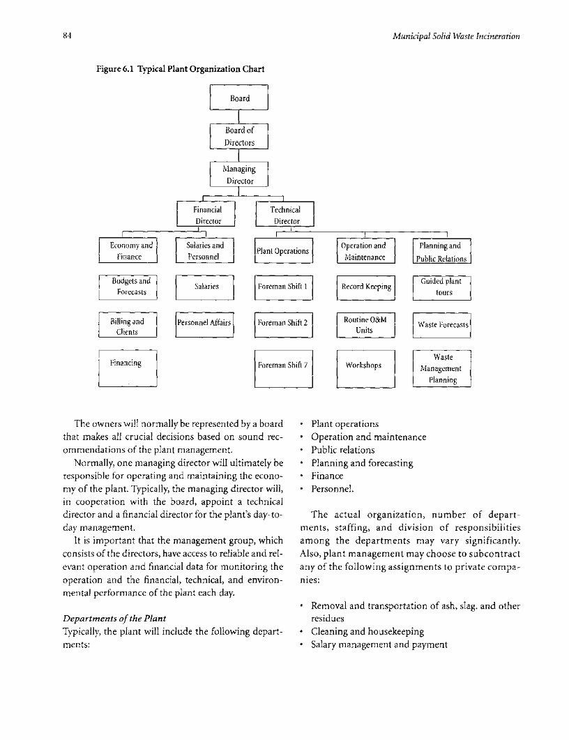
84 Municipal Solid Waste Incineration
Figure 6.1 Typical Plant Organization Chart
Board
Board of
Directors
I
|Managing |
Director
| Financial | |Technical|| Director | | Director |
Economy and Salaries and lant Operations Operation and Planning andFinance Personnel I LP |Maintenance Public Relations
Budgets and Salaries Foreman Shift I Record Keeping Guided plantForecasts tours
Billing and Personnel Affairs Foreman Shift 2 Routine O&M Waste ForecastsClients Units
WasteFinancing Foreman Shift 7 Workshops Management
Planning
The owners will normally be represented by a board * Plant operationsthat makes all crucial decisions based on sound rec- * Operation and maintenanceommendations of the plant management. * Public relations
Normally, one managing director will ultimately be * Planning and forecastingresponsible for operating and maintaining the econo- * Financemy of the plant. Typically, the managing director will, * Personnel.in cooperation with the board, appoint a technicaldirector and a financial director for the plant's day-to- The actual organization, number of depart-day management. ments, staffing, and division of responsibilities
It is important that the management group, which among the departments may vary significantly.consists of the directors, have access to reliable and rel- Also, plant management may choose to subcontractevant operation and financial data for monitoring the any of the following assignments to private compa-operation and the financial, technical, and environ- nies:mental performance of the plant each day.
. Removal and transportation of ash, slag. and otherDepartments of the Plant residuesTypically, the plant will include the following depart- * Cleaning and housekeepingments: * Salary management and payment

Operation and Maintenance 85
* Operation and maintenance of specific units of the ing littering or spreading of dust. Such vehicles can be
plant purchased and operated by the plant, or the services
* Periodic testing and analysis of effluents and emis- can be subcontracted to a private company. It is impor-
sions tant to make sure there is sufficient intermediate stor-
* Specific planning and feasibility studies required for age capacity and reliable and frequent transportation.
plant development.
Training of Workers, Codes of Practice, and
Crucial Supplies and External Services Occupational Safety and Health
The following supplies and external services are crucial The personnel or human resource development
for continued operation of the incineration plant: departments should be responsible for training work-
ers. The skills and training courses in table 6.1 may be
* Continuous and steady high-voltage power supply required.
* Water Codes of practices or documented work procedures
* Removal of residues (slag, ash and air pollution con- should be prepared for all key plant activities and facil-
trol residues)-that is, availability of an engineered ities. Furthermore, there should be contingency plans
and sanitary landfill for residues in case of accidents or equipment failure.
* Availability of spare parts-and sufficient local and The documentation should instruct the workers
foreign currency for purchasing spares how to operate the equipment, and what to do if it fails
* Availability of consumables (such as lime, oil, and or in case of accidents. Such documents can be used in
lubricants). new employee orientation, as well as a reference source
for employees throughout the year.
Typically, if the waste does not contain hazardous Equipment suppliers should be required to submit
compounds, the quality of the slag and ashes will allow work procedures as part of the contract. Ideally, these
for recycling after sieving-for example, for roadfill. should be used for preparing an integrated work pro-
Hence, slag maybe transported to a sorting area, reject- cedure for the entire plant. The integrated proce-
ed slag and ashes may be transported to a landfill, and dures should be available in the operator's room and
APC residues may go to secure landfill sections. with shift supervisors and other key personnel.
In any case, the residues should be transported by Relevant excerpts should be placed at each machine
suitable vehicles, in fully contained loads, thus avoid- or equipment.
Table 6.1 Required Skills, Education, and Background for Operating an Incinerator
Employees Number Basic skills required Additional training courses required
Managing, financial, and 3 Documented management skills (such as Public utility managementtechnical directors previous experience and relevant education)
Economists, accountants, 6 Documented skills in economy, finance, Electronic information managementand office clerks or accounting systems
Plant operators >14 Documented skills and certificates as Occupational safety and health (OSH),chief facility operator or shift supervisors and plant operation
Crane operators >7 Experience in machine operation Sorting and homogenization of wastebefore feeding, and fire extinguishing
Shift supervisors >7 Good management and planning skills; OSH, first aid, and plant operationlong experience with plant operation
Mechanics >5 Qualified mechanics, qualified welders OSH and first aidElectricians >2 Qualified electricians OSH and first aidGeneral workers 30 Job-specific OSH and first aid


7 Environmental Impact andOccupational Health
Key Issues tor (basic emission control, dust<30mg/Nm3).
MSW incineration plants are generally located close todensely populated areas for economic reasons (e.g., / / / A controlled and well-operated landfillsale of energy, transport distance). Any negative envi- must be available for the disposal ofronmental effects of the plant can influence a great residues.number of people. A combination of planning andtechnical measures is required to minimize such / / To avoid noise, dust, and odor in residentialimpacts. areas, MSW incineration plants should be
Of the MSW incineration residues, only the slag can located in land-use zones dedicated tobe considered environmentally safe to reuse. The flue medium or heavy industry.gas cleaning residues are much more soluble than theoriginal wastes and have to be disposed of in an appro- / / The stack should be twice the height of thepriately designed and operated controlled landfill to tallest building within 1.0 km, or at least 70avoid negative impacts on ground or surface waters. meters high.
MSW incineration plants may have a negativeimpact on the air quality of a fairly large area. The wasteitself can create odor and dust in the immediate sur- Environmental Impactroundings, and flue gases containing particles andvapors are spread over a larger area-reducing the The environmental impact of the construction andoverall air quality if insufficiently treated. operation of an MSW incineration plant should be
Municipal solid waste may contain hazardous and assessed according to the requirements laid down in theinfectious matter (although it is not supposed to). World Bank Operational Directive (OD) 4.01:Combined with the release of dust containing endo- Environmental Assessment. A waste incineration planttoxins, this risks the health of those employed at the belongs to category A in the OD-and therefore, a fullreception area of the incineration plant. Special pre- environmental assessment should be conducted.cautions have to be taken to minimize such risks. The present guidelines do not substitute an envi-
Occupational health risk and protective measures ronmental assessment carried out in accordance withfor the rest of the plant are similar to those identified OD 4.01, but describes the impacts to be expected fromor required at places such as coal-fired power plants. an incineration plant and a selection of measures that
can be taken to remediate them.A properly constructed and operated waste inciner-
Key Criteria ation plant is expected to be comparable to medium to*/ */ / The flue gas treatment installation must be heavy industrial activities as far as environmental
capable of removing dust at least as effi- impact, transport requirements and other infrastruc-ciently as a two-stage electrostatic precipita- ture needs, and potential public nuisances.
87

88 Municipal Solid Waste Incineration
Because a waste incineration plants is similar to emission. It may be necessary to specify wall and ceil-medium to heavy industrial activities, it should be ing structures with an appropriate sound reduction orlocated within a zone dedicated for industrial activities. absorption index to keep noise from spreading via theBesides, because it is similar to a power plant in its ener- building itself, and to safeguard the working environ-gy output and residues, it should be located near power ment in the buildings.plants, especially those that are coal fired. The draught fans and the flue gas fans are, together
This section describes possible environmental with the stack, the most significant sources of noise inimpacts and the measures designed to reduce them theenvironment.Ventilatorswilloftenbelocatedatthe(elaborated on in the chapter on Plant Location). building roof and therefore also produce noise in the
surroundings if not properly muffled. If the plant isNoise located close to residential areas, it may be necessary toNoise generated at incineration plants originates from provide the ventilators with attenuators or acoustictransportation of waste and treatment residues to and enclosures. This is quite expensive and further prooffrom the plant, handling waste and residues within the that the plant should be located within an industrialplant premises, and noise emissions from the installed area.equipment. Except for the traffic to and from the plant, all of the
Massive transportation of waste and residues will sources of noise can be assumed to operate for 24 hourstake place on the roads near the plant. This can hardly a day and 7 days a week all year round. If the incinera-be avoided and is one reasons an incineration plant tion is combined with a plant for recycling of cindersshould be located within an industrial zone or estate and slag for construction purposes, the necessary treat-well connected to the major roads of the waste catch- ment (mechanical sorting mainly) can be limited to thement area. If the vehicles arriving at or leaving the plant day shift.are tempted to make shortcuts through residentialareas, forced routes for the trucks may have to be intro- Odors
duced. The combustion process destroys all odor-emittingWaste and residue handling comprises unloading substances in the waste, and the slag and fly ash are ster-
the waste into a reception and storage pit and handling ile and odorless after cooling.and treating slag and flue gas cleaning residues from the MSW incineration plant odor is thus emitted main-combustion process. Waste should be unloaded within ly from handling and storing waste before combustion.a confined or semiconfined building to prevent storm The main sources are the unloading activities and thewater from entering the pit and to keep wind from waste storage pit. The pit or hopper serves as a bufferspreading dust and lightweight wastes. Confinement to equalize the feeding of the furnaces, and will thuswill also protect against noise emissions from these always contain a variable amount of waste. Some of theactivities. Slag and fly ash should also be handled inside waste may be in the pit for several days before being feda building that protects against climate and emissions to the furnace. In this period, the putrescible waste willof noise, odor, dust, and the like. degrade under anaerobic conditions-especially at
Internal traffic on the premises and the noisy activ- high ambient temperatures-and emit an unpleasantities at ground level can be screened off by acoustic smell.screens through soil barriers. The necessary handling of the waste in and around
The main equipment installed at a waste incinera- the pit will create odor-and will make bacteria andtion plant includes the overhead crane that feeds the toxins airborne.waste into the hopper or furnace, the furnace with To avoid emitting foul air into the environment, themoving grate, the slag collection and cooling system, waste pit and the feeding section of the plant hopperthe boiler, the flue gas cleaning equipment, fans, and area must be enclosed with roof and walls. The air forventilators. Most of the equipment will be located the combustion process must be abstracted from theinside the incinerator building, which muffles the noise top of this more or less open room (that is, from the

Environmental Impact and Occupational Health 89
crane or hopper deck) to generate an induced air flow cury, which is only poorly removed by dry filters). Theinto the room and keep foul-smelling substances from scrubbers will also remove the flue gas content of acidescaping. substances, including hydrogen fluoride (HF), hydro-
Besides this, the unavoidable spillage must be gen chloride (HCl), and sulfuric acid (H2SO4). Ancleaned and the general area must be kept tidy. This environmental drawback of the wet systems is the out-must be specified in the staff training program and in put of heavily polluted waste water, which requiresthe plant's operation manuals. advanced treatment to remove substances such as
heavy metals before discharge.AirEmissions The requirements for air pollution reduction mustAirborne pollutants from the combustion process are depend on the general environmental requirements ofemitted through the stack. Assuming an optimal com- the country. There should be a reasonable relationbustion process for complete destruction of particles between the requirements for municipal waste inciner-and gases, the applied flue gas cleaning and the height ators and the requirements for other industrialof the stack are decisive for the resulting contribution processes.to the air quality. The anticipated emissions, as a func- The stack height is decisive for the dilution of thetion of cleaning technology, are described in detail in flue gases in the environment. A minimum height isthe chapter on Air Pollution Control. required to prevent the plume from reaching the
To reduce the pollution load on the atmosphere ground or entering tall buildings. This minimumfrom the combustion process, various measures can be height will depend on the local atmospheric condi-applied, as follows (described withan increasing degree tions, the topography (flat or hilly), and the height ofof complexity, cost, and efficiency). the buildings within a radius of at least 1.0 km. The
A two-field electrostatic precipitator (ESP) is con- stack height should be decided on the basis of com-sidered the minimum requirement for flue gas clean- puter modeling, and should never be less than 70ing at an MSW incineration plant. The ESP will remove meters.the dust from the flue gas to a level of 20 to 30 mg/Nm3.Most of the heavy metals adhering to the dust, such as Waste Generation and Access to Landfilllead, will be removed rather efficiently from the flue In the combustion process, the volume of the waste willgas. The advantage of the ESP is that it is robust, inex- be reduced by approximately 90 percent and the weightpensive to operate and may even function (as a settling by 70 to 75 percent. The output (residue) from the com-chamber)if the power supply is interrupted. It also bustion process will mainly be bottom ash (slag), andoperates at rather high flue gas temperatures and thus the boiler and fly ash will account for only a small per-requires limited cooling of the flue gas only. cent of the waste incinerated.
A bag-house filter will clean the flue gas better for the In addition to the slag, and boiler and fly ash, thesmallest particles, and better remove heavy metals, than plant may generate residues from more advanced dry,the ESP. The disadvantages of the bag-house filter are semi-dry and wet flue gas cleaning processes. Thethe cost of operation and the vulnerability-as the flue amount and its environmental characteristics willgas must be cooled before the filter to around 1500 C, depend on the technology applied.and there is a risk that sparks from the combustion will The slag from a well-operated waste incinerator willburn the bags. Thus, bag-house filters require a flame be burnt out, with only a small amount of organicand spark arrestor. Bag-house filters are also vulnerable material. Besides, the heavy metals in the slag, whichwhen the combustion starts and closes, as the flue gas are normally leachable, will to some extent become vit-will be cool and moist and must bypass the bag filter. rified and thus insoluble. The slag may therefore be
Both an ESP and a bag-house filter may be com- used as road construction material, reducing the land-bined with various scrubbers in which dry or wet lime fill capacity requirement.is injected in the flue gas stream, thus further reducing The boiler and fly ash and other residues will, how-the content of dust and heavy metals (particularly mer- ever, need to be disposed of in a controlled landfill, as

90 Municipal Solid Waste Incineration
will the incombustible waste generated in the area. It is residues (spills) and thus have a relatively high concen-therefore absolutely necessary to have a well-engi- tration of organic substances-at the same level asneered and operated landfill available for these types of household effluents.waste.
Water Supply Occupational Safety and HealthSupply of water is necessary for feed water to boilersand for various processes at an MSW incineration Solid waste handling exposes staff to dust, microor-plant: cleansing, slag cooling, flue gas scrubbers (if ganisms including gram-negative bacteria, fungi, andimplemented), and staff sanitary purposes. endotoxins, and gases and odor from biological
Slag cooling water has no quality requirements, so decomposition of the waste. MSW incineration plantspolluted river water or groundwater can be used. The further involve a risk of exposure to combustion prod-water consumption for slag cooling can be assumed to ucts-for example, gases and particles at various stagesbe in the magnitude of 0.05 to 0.01 m3/metric ton of of the process and applied chemicals.waste if state-of-the-art slag extractors are applied. Combustion products can be inhaled or ingested.
Water will also be used if flue gas scrubbers or The incineration plant must be designed, operated,semidry reactors are installed. Drinking water quality and maintained to minimize human exposure. Thisis not required for this process, but the water must requires application of a combination of permanenthave a relatively low solid content, so lime can be installations and personal protection equipment.diluted in it and sprayed through nozzles into the fluegas stream. The water consumption will depend on Airborne Pollutionthe technology applied, ranging from about 0.1 Workers in the waste reception hall are exposed tom3/metric ton of waste in the semidry absorption exhaust fumes from the trucks delivering the waste.process (which does not generate wastewater) to During any manual unloading, the engines should beabout 0.25 to 0.4 m3 /metric tons of waste in the wet turned off to minimize such exposure. The air qualityprocess (which generates 0.07 to 0.15 m3 of waste- in the reception hall is also negatively influenced bywater per metric ton). odor, dust, and micro-organisms released during
unloading. Decomposition of waste in the pit/hopperWastewater Discharge further degrades the air quality. Prolonged storage ofThe wastewater generated from wet processes will have large volumes of waste may result in anaerobic condi-high concentrations of salt (mainly as chloride) and tions followed by depletion of oxygen and formation ofsoluble heavy metals. Cadmium can be assumed to be methane.the most important of these with regard to emission Leaks in the furnace, flue gas, and duct systems willlimits. The actual concentrations will depend on the emit dust and flue gases inside the buildings. At the endcomposition of the combusted waste. of the plant, handling of slag, and fly ash and lime used
The recipient must therefore be relatively robust for advanced flue gas treatment increases the amount(that is, the discharge must be highly diluted). The level of suspended matter in the air.of discharge will depend on the technology applied, Generally, exposure to these health hazards must beranging from almost none if water is only used for slag minimized through proper design of buildings, equip-cooling (in which case, almost all of thewaterwill evap- ment, and installations. The building layout shouldorate) to 0.3 m3/metric ton of waste if wet flue gas avoid direct connection between high-risk areas andscrubbers are installed. permanently staffed rooms. Surfaces must be easy to
Aside from the wastewater discharged from the clean and designed to prevent deposition and accumu-processes at the incineration plant, cleaning water and lation of dust, especially in hard-to-reach places. Plentystorm water will be discharged from the area. This of taps should be installed for washing and hosingwater can be assumed to be contaminated with waste down floors (rather than sweeping).

Environmental Impact and Occupational Health 91
Maintaining a slightly elevated air pressure in per- In areas where the noise level exceeds 85 dB(A), earmanently manned rooms (such as the crane operator plugs or equivalently efficient protection should beand control rooms), as well as offices, canteens, and mandatory.kitchens, will reduce the dust and gases entering theseareas. Chemicals
The operation manual for the plant must call for The Chemicals Convention should be followed-routine checks for, and repair of, leaks in the equip- including assessing all applied hazardous chemicals inment. Cleaning and maintenance can increase expo- respect to safe usage and taking necessary labor pro-sure and should be countered through application of tection measures.personal protection devices. Safety Data Sheets must be provided by the suppli-
Masks for protection against micro-organisms (type ers of hazardous chemicals. The employer shouldP3) should be used in the waste reception area. In dusty ensure that all necessary precautions are taken.areas with concentrations of dust larger than 3mg/m3 ,type P2 masks should be applied. Physiology
Work stations should avoid torsion and bend-forwardHeat positions. Work must be executed in front of and close toThe temperature in the furnace hall may be elevated the body-that is, the level of the footbridges should beconsiderably above ambient temperature and even adjusted according to the level of the actual site of work.become uncomfortable. Working in this area induces a Ergonomic strain caused by lifting, pulling, andrisk of dizziness, sickness, visual disturbance, and pushing of heavy parts should be minimized throughheadaches. lifts and cranes. The floors should be level, with suffi-
The room temperature and heat radiation should be cient slopes for drainage of cleaning water only.reduced through ventilation and insulating or coveringhot surfaces. Efficient ventilation consists of vents for Risk of Accidentsexhaust of warm air from the ceiling above the furnaces Experience shows that the main risks of accidents at anand supply of fresh air through openings or forced ven- incineration plant are falls from great height (into thetilation vents. pit or down from the footbridges), collisions with
Drinking water should be available throughout the trucks transporting waste or residues, accidents atplant. rotating equipment, scalding by hot water or steam,
equipment failure, explosions, and fire.Vibrations Footbridges and elevated platforms must be equippedThe vibrations and sound pressure emitted from with safety rails-if not, access must be restricted.numerous machines and activities may reach a level of Motor traffic must be separated from pedestriansconcern to occupational health and safety. Vibration wherever possible.dampers should be applied whenever required. Noisy Machinery must be shielded against moving andequipment such as turbines and compressors must be rotating parts-and should be unable to operate ifshielded or placed in special rooms with sound-absorb- these shields are not installed properly. Emergencying cladding on the walls. Large ventilators should be stops must be installed in case of accidents.located where the noise level is of no concern or Emergency response and evacuation plans must beequipped with noise-reducing intake and outlet units. established.

Bibliography
Chandler, A. John. September 1997."Municipal solid waste residues." Studies in Environmental Science 67, Elsevier
incineration technologies." A presentation for the World Science B.V., Amsterdam.
Bank Seminar on Waste Management by A.J.Chandler &
Associates Ltd. Ontario, Canada. McCarthy/RAMB0LL J.V. April 1998. Richmond Hill
Incinerator, Final Summary Report. Isle of Man Government.
Dalager, S. U. Marxen, I.Nymann, T. Hulgaard. May 1998.
"Affaldsteknologi, Kapitel 4.2 Forbrending: princip og RAMB0LL. September 1993. "Review of Taiwan Tender
teknologi." RAMB0LL, Denmark. Document & Plant Design Specification." China Engineering
Consultants, Inc.
General Conference of the International Labor Organization.
1990. Chemicals Convention. Thome-Kozmiensky, Karl Joachim.1994. Thermische abfallbe-
handlung, zweite Auflage EF-Verlag Fur energie- und
Hjelmar, 0. 1996 "Disposal Strategies for Municipal Solid Waste umwelttechnik GMBH. Berlin, Germany.
Incinerator Residues." Journal of Hazardous Materials.
International Ash Working Group: A.J. Chandler, T.T. Eighmy,
J. HartlenO. Hjelmar, D.S. Kosson, S.E. Sawell, H.A. van der
Sloot, J. Vehlow.1997. "Municipal solid waste incinerator
93


Municipal Solid Waste Incineration Checklist
The checklist below is intended to serve two purposes:
First, the checklist is to be used in the planning process, when a decision is to be made on whether to build anincineration plant or not. A range of questions should be answered before the decision is made. These questionsare generally the ones in sections 1-5 below, plus the initial questions in sections 8-10.
Second, the checklist is intended for use in feasibility studies in relation to outline projects for incineration plants.In this context, all of the questions in the checklist should be answered and appropriate action taken.
The checklist is constructed as a simple table with options. Option A is the best and option D the poorest. Often,checking the item in column D will result in a "no-go" decision. Those questions deemed most crucial for the deci-sion (the "killer" answers) are shadowed in column D (and in some instances column C).
Throughout the checklist, LVC means Lower Calorific Value; MSW means Municipal Solid Waste, which includeswaste similar to MSW from commerce, trade, and industry; and SWM means Solid Waste Management.
PARAMETER A B D .'Explanation A check in column A A check in column B A check in column C A check in column D
means that the condi- means that although means that conditions means that conditionstions are close to opti- the conditions are not for establishing a MSW for establishing a MSWmal for establishing a optimal, establishing a incineration plant are incinerator are poor.MSW incineration MSW incineration doubtful. Some (shad- The shadowed answersplant plant could be consid- owed) assumptions are "killer" answers
ered further may be "killer" answers
Waste The characteristics z The characteristics LJ The characteristics LI Tht h d. j;lcharacteristics of the waste are of the waste are of the waste are -fthw t not
fully established by assessed by repre- assessed from grab -sampling and sentative sampling samples and stan-analysis and analysis dard data
Annual variation The annual varia- L The annual varia- LI The annual varia- LI .in characteristics tion is fully estab- tion is assessed by tion is assessed
lished by sampling representative sam- from grab sampling X onand analysis pling and analysis
95

96 Municipal Solid WVaste Incineration
Calorific value of The LVC is more 2 The LVC is 8 MJ/kg LI The LVC is 6 MJ/kg 2 Th LVCis priodi- Jwaste than 8 MJ/kg all or more 80% of the or more all year cally les ta 6
year round time and never less round and the M or the annu-than 7 MJ/kg annual average is 7 all avere is less
MJ/kg or more t 7 MJ/kg
Amount of ivsaste The annual amount 2 The annual amount 2 The annual amount O The annual amount; of waste is more than of waste is around of waste is more than of waste is less than100,000 metric tons 100,000 metrtic tons 50,000 metric tons 50,000 metritons
Weekly variation of Variations do not J Variations are 20% 2 Variations are 30% 0/s Variationsdare0% Eliamount exceed 20% to 30% to 50% or more
Forecasts of waste Forecast is based on 2 Rough forecast 2 Rou st on J No forecast exists 2generation survey on waste exists on waste waste amounts
amounts and com- amounts and com- extsposition (including position (includingLVC) for the next LVC)10 years
M\zain solid wvaste More than 10 years 2 5 to 10 years old 2 0 to 5 years old 2 Not yet i Limanagement old :m:ented 0 00 0 000:S 0 ;S: 00 ::organization
Regulations Effective regula- L Regulations are in 2 Regulations exist 2 Solid waste regula- 2tions exist regard- force regarding regarding collection tions exist buting collection and household and haz- and transport of enforcement isdisposal of all types ardous wastes only household wastes weakof wastes only
Solid waste owner- The waste manage- 2 The waste manage- 2 The waste manage- 2 Waste b tship ment organization ment organization ment organization the generator, who
has ownership of has full ownership has ownership of can dispose of itall waste of all waste in dedi- waste placed on freely, e.g, bytrans-
cated dust bins and public roads. ferrng osip.containers
Solid waste collection A single organiza- 2 Household and 2 Household waste L Wate collection is Lition is managing commercial wastes collection is man- performed by mull-the collection of all collection is man- aged by one or a few tiple independentsolid waste aged by one organi- organizations, and operators
zation. Large opera- some large opera-tors are found in tors exist in thethe industrial sector commercial and
industrial and sector
Present organized Incineration 2 Composting in u Sorting and recy- 2 No organized waste Lsvaste treatment mechanical plant cling activities treatment
Present recycling Recycling is orga- 2 Recycling is orga- 2 Scavengers are 2 Scavengers are pre- 2nized and based on nized for industrial active in the waste sent at the landfillsource sorting waste only collection stage site

Checklist 97
PARAMEThR A ... D
Present waste disposal All solid waste is c 75% of all waste is LI Household waste is c A can t i ]disposed of in con- disposed of in con- disposed of in a thewastee flntrolled and well- trolled and well- controlled and se8o iS sedoperated landfills operated landfills well-operated land- ofit uncontrolled
fill or du p
MSW incinerator The MSW incine- c The MSW incine- Li The MSW incine- uMWincier- .
organizational rator is an integrat- rator is an indepen- rator is an indepen- a7r is ait -
position ed part of the SWM dent MSW treat- dent MSW treat- dm-system ment plant with ment plant with menftI ptant'wihoUt
close formal rela- informal relations liktohe ̀ WMtions to the SWM to the SWM system system .
system
MWS incinerator Owned by public U Owned by public/ c Owned by private u n private a
ownership SWM company private utility com- SWM company atg w egy win-pany (power or mmer s a lage -heat production)in
MSW incinerator The MWS incinera- u The MWS incinera- i Th M ciner j
rights and duties tor is granted right tor is granted right -w a ei
to receive all com- to receive all com- abustible waste and bustible household e teanloe totobliged to ensure waste and obligedthe necessary to ensure the neces- ; A sicapacity sary capacity
Energy buyerl One scn paa lic/ b One power compa- Many small power g antiofuthenergy r
distributor private utility com- ny and one district and/or district pl ypany heating company heating companies
,lvailability of District heating sys- Fl District heating sys- LI Power lines LI Niwr to be -
distribution networks tem and power tem i dlines
Incineration energy All recovered heat Lj Most recovered Some energy will be Lj A substantial can at all times be energy can be uti- used for power gen- amount of the sur-utilized for district lized for a combi- eration; the plus energy will beheating purposes nation of power remaining will be cooled off
and heat cooled off
Cost and expense Stabe predictable Uncertainty about i ;.. stability plant expenses and expenses or rev- -...-.
revenues can be enuesassumed

98 Municipal Solid Waste Incineration
PARAMIETERC A CD
VWtaste supply stability Long-term con- U Contracts on waste U Contracts on waste U N0o or itl wste l
tracts on delivery of deliverv correspon- delivery correspon- sply security
all waste to inciner- ding to 80% of ding to 60% ofation plant; 100% plant capacity plant capacitycapacity utilization
Current waste All costs of waste U Households pay a U Costs of waste U All costs are paid Umanagement charges collection and dis- waste management management is from the public
posal are paid by fee. A tipping fee is paid partly by users budgetusers collected from and partly from the
other users of, e.g., public budgetlandfills
Incineration charges Costs of incinera- U The incineration U The incineration U The incineration Ution are covered by plants collects a tip- plant collects a tip- plant must collectthe budget. The ping fee, which cov- ping fee; remaining its own tipping feeauthorities charge a ers all costs costs are covered by from individualwaste management the public budget usersfee on householdsand commercialactivities
Competitive charges MSW incineration U MSW incineration U MSW incineration U,tipping fee is tipping fee is equaltpinfeiscnsmaller than the to or a little higher stipping fee for, than the tipping fee than theiing feee.g., landfilling for, e.g., landfilling for,e.g.,lnlling
Energy sale Government- U Agreement signed U Letter of intent U No agreement Uagreement(s) approved agree- but not yet available reached
ment or firm con- approved or con-tract available tract agreed but not
signed
Budget Plant will have its U The plant will have U Plant economy will U All expense must Uown budget and its own budget be part of a public be approve ofinspecial privileges budget adan t -eregarding foreign nd agency
currency procure-ment
Cash Jlow Plant budget and U Pla b4t an U-revenue allows for rvnede opurchase of neces- r purchase
sary and sufficient of necessary andspare parts and sfiin prconsumables > t > a
Foreign currency Unrestricted access U N c to foe gn Uavailability to foreign currency cu spate
for spare parts pur- parts purchasechase

Clhecklist 99
PARAMETER A B C D
S. Plant Localization
Air quallity im71pact Windv area, inver- U Few inversions and I Occasional but U Frequent and pro- Usions nonexistent smog situations short inversion and longed inversion
smog situations and smog situa-tions
Zotiing of plant IoLality Heavy industry U Medium to heavy U Medium to heavy U Light industry Uindustry industry
Distance to residet,tial > 500 meters U 300-500 meters U 200-300 meters U < 200 meters O
areas/zones
Main access roads Existing major UA Planned major O Main roads O Local roads only LIroads and roadsthoroughfares
Distanice to waste < 1/2 hourbytruck U 1/2-lhourbytruck 1 hour bytruck a > 1 hour by truck Ugeneration center
Sllfficient capacity < 500 meters from U 500-1,000 meters U 1,000-2,000 meters U > 2,000 meters O
public utilities (wvater, site from site from sitepower, an1d sewers)
Connection poinlt tor < 1,000 meters U 1,000-2,000 meters U 2,000-3,000 meters U > 3,000 meters Usurplus energy is from site from site from site from siteavailable
6. IncinerationTechnology
Waste pretreatmnoit The waste can be U Mechanical sorting U Manual sorting out J The waste needs U..fed into the incin- out and crushing of and crushing of extensive pretreat-erator "as received" large items is neces- large items is neces- ment (sorting,after mixing in sary sary crushing, homoge-waste pit nizing) before
incineration
Furnace tech nology The incinerator U The incinerator U The incinerator LIconcept is based on concept is a concept is fluidizedmass burning rotating kiln bed or other tech-principle nology unproven in
MSW combustion
Incinierator line Each incinerator U Each incinerator U Each incinerator U Each incinerator Ucapacity line has a capacity line has a capacity line has a capacity line has a capacity
between IO and 20 higher than 20 between 6 and 10 of less than 6metric tons/hour metric tons/hour metric tons/hour metric tons/hour
Numbitier of incinecrtor The NISW incinera- U The MSW incinera- Ulines tion plants has two tion plants has one
or more incinera- incineration linetion lines

100 Municipal Solid Waste Incineration
Flue gas burnout The flue gas is fully J The r e j
burnt out in an in A are not metafter-burner, result-ing in emissionconcentration ofCO < 50 mg/Nm3
TOC < 10 mg/Nm3
Startup and support The furnace is pro- J The furnace has noburner vided with burners sr ad supot
to heat the inciner- burnersator during startupand keep afterburn- Yer temperatures upin case of lowcalorific value ofwaste
Suipplier's experience The supplier has L The supplier has O The supplier has U The supplier hextensive experi- good experience in some experience in experience n MSWence in MSW MSW incineration MSW incineration incineratioincineration andnumerous refer-ences
F lue gas temperature The flue gas tem- J The flu g
atter boiler perature is below peatr is above 0 1 50'-200' C to 200Wallow for optimumrenergy recovery andflue gas cleaning
Energy recovery The recovered ener- U The recovered ener- U The recovered ener- U The energy is Usystem gy is converted to gy is converted to gy is converted to cooled away
hot water for dis- steam for power steam for powertrict heating or low- production or productionpressure steam for industrial use andindustrial purposes for district heating
e0O 1119
Landfill Controlled and U Controlled and U Controlled and U o o an Uwell-operated well-operated land- well-operated land w p dlandfills exist for all fills exist except for flseitfrdms il xstypes of waste hazardous wastes tic waste. Extensionincluding haz- with section forardous materials incineration
residues feasibleSlag can be utilized
Residue utilization Most residues can U in construction; U No utilization Libe utilized for flue gas cleaning options for residuesindustrial or con- residues must bestruction purposes landfilled

Checklist 101
PARAMETER A B C D
Availability of staff Qualified staff 2 The authorities L An HRD organiza- L Competition for 2available in suffi- assign staff with the tion is in place for qualified staff is
cient numbers necessary skills staff training fierce
Salaries The incineration L Market price 2 Incentives in addi- L The plant is unable Iplant can pay mar- salaries are paid to tion to the basic to pay competitive
ket price salaries managers and salaries prevent salaries for skilled
skilled staff excessive staff staffturn-over
Plant A builder's imple- 2 A builder's imple- 2 A builder's imple- 2 No implementation Limplementation mentation mentation mentation organization is
organization organization is organization is organization is established
established with established with establishedskilled staff and staff and consul-consultants experi- tantsenced in MSWincineration
Plant organization A clear and well- 2 An outline plant L An outline plant 2 No plant organiza- Lstructured plant management orga- management orga- tion is established
management orga- nization is drafted nization is draftednization exists and approved
Operation and The supplier or an L The supplier or an L The suppler will L None of the provi- Lmaintenance independent independent provide training of sion under A will
manuals, training of consultant will pro- consultant will pro- staff on manage- be made
staff, plant vide organizational vide organizational ment level
monitoring setup, relevant setup, relevantmanuals, staff train- manuals, staffing at all levels, and training at all levelsthe SMW organiza-tion will utilize it
Environmental Emission standards 2 Emission standards 2 Emission standards 2standards for incineration for incineration for incineration
plants at medium plants at basic level plants do not exist
level
Environmental Independent public 2 Nearly independent 2 The public authori- 2administration authority responsi- public authority ty responsible for
ble for environ- responsible for environmental per-
mental permit, environmental per- mit, supervision,
supervision, and mit, supervision, and enforcement
enforcement and enforcement owns the MSWincinerator

102 Msunicipal Solid Waste Incineration
PARAMT E - A B C D
Flue gas treatment The flue gas treat- U The flue gas treat- U The flue gas treat- L No flue Fgas treat- LUment plant meets ment plant meets ment plant meets ment plant presentnational emission medium emission basic emissionstandards standards with standards with
respect to dust respect to dust(<30mg/Nm3) and (<30mg/Nm3)HCI (<50mg/Nm3)
Flue gas emission Stack is sufficiently U Stack height results -i Stack height results U Flue gas is emitted Uhigh to avoid in few and minor in frequent fromia low stack
exceeding ambient instances of exceed- instances of exceed- and causes majorair standards ing ambient air ing ambient air instances of exceed-
standards standards ing ambient airstandards
Odor emission The plant is con- U The plant will U The plant will U The plant will cause Ustructed and oper- result in occasional result in frequent unacceptable odorated so that odor odor emissions in odor emissions in emissions in theinconveniences do the neighborhood the neighborhood ineighborhodnot appear
Wastewater Wastewater dis- U Wsteater is dis- 1discharge charge meets charged untreated
national standards and does not meetnationl stanars
Noise emissions Noise emission is U Noise emission will U Noise emission will 3 I Noise emission will Usufficiently muffled lead to minor lead to major lead to unaccept-to avoid any incon- inconveniences in inconveniences in able noise level inveniences in the the neighborhood the neighborhood the neiborhoodtneighborhood
Monitoring A monitoring sys- U A monitoring sys- U No bmonitoring LI
tem for all relevant tem for basic envi- foreseen lo takeenvironmental ronmental parame- placeparameters is ters is establishedestablished
Building layoui Same as B plus ade- U Same as C plus sep- U Separation between D Direct access from Uquate emergency aration between permanently staffed furnace hall, andaccess/exits. Labor roads for vehicles rooms and produc- waste receptionprotection and and pedestrian pas- tion areas. Showers area to controlphysiological mea- sages and dressing rooms roomsures fully included for staffin the design
Ventilation Same as B plus U Same as C plus U Forced ventilation U Ventilation of Umaintenance of ele- additional point- in all rooms with permanent workvated pressure in all source ventilation frequent work. stations onlypermanent work at critical places, Combustion air isstations and recre- e.g., where chemi- drawn from wasteational rooms cals are handled pit area

Checklist 103
PARAMETER A B C D
Mechanical plant State-of-the-art L I Low-noise equip- LI Basic occupational Li Occupational Liequipment, e.g., low ment with basic health and safety health and safety
noise and elaborate protection devices measures included not considered
safety measures
Manual of Same as B plus reg- Li Same as C plus Li Basic manual exists; Li No operation and Lioperation and ular emergency HRD organization organizational safety manual
safety response exercises for enforcement of responsibilities availableregulations and established at alltraining of new levelsstaff


Distributors of World Bank Group Publications
Prices and credit terms vary frem CZECH REPUBLIC INDIA Eulyoo Publishing Ca., Ltd. PERU SWEDENcsuntry to ceuntry. Conselt,your, LitS NLPrden Allied Publishers Ltd. 40-1, Susong-Deng Editerial Desarretllo LA Wennergren-Wiltiarns A8local dist ributor hefore placing va 22 751 Mount Reed JEngro-Gu Apurtado 3824, ica 242 OF 106 R 0 Due 1305order 130 00 Prague 3 Madras - 60,1 002 Seoul Lima 1 S- 171 25 Seine
Tel: (420 21 2423 1486 Tele (91 4 52-3938 Tel: (82 2)734-3515 Tel: (51 14) 285380 Tel: (46 ) 705-97-50ARGENTINA Fax: (4202I2423 1114 Fax: (91 4)852-0649 Fax: (82 2) 732-9154 Fae: (51 14) 286628 ax: (4168)27-00-71World Publications SA URL http://www.nis.cz INDONESIA LEBANON PHIUPPINES-i: milwwi.seAu. Cordoba 1877 DENMARK Pt. Indira Limited Libraiie du Liban International Booksource Center Inc. SWITZERLANDt120 Ciudud do Buenos Aires SamfundsLitteratur Jalan Borobudur220 P.O. Box 11-9232 1127-A Anhpolo St, Barangay, Librairie Payot Service lnstitutionnelTel: (5411r 4815-8156 Rosenoerns Alle11 PIO. Box 181 Beirut Venezuela Cttes-de-Montbenon30uas. (54w1 r (4815-8158 DK-1970 Frederiksberg C Jakarta 10320 Tel: (9619) 217 944 Makati City 1 Lausanne
b-mull: [email protected] ar o Tel: (45 35T 351942 Tel: (62 21) 390-4290 Fax: (961 r) 217 434 Tel: (63 2) 896 6501 6505; 6507 Tel: (41 21) 341-3229AUSTRALIA, FIJI, PAPUA NEW Fax: (45 35) 357822 FaxP (62 21) 390-4289 E-maul: hsayegh@librarie-deu- Fax: (63 2) 8961741 Fax: (41 21) 341-3235GUINEA, SOLOMDN ISLANDS, URL. http://www.sl.cbs.dk IRAN lihban.com.lb POLND ADECO Van DiermenVANUATU, AND SAMOA LiECUADOR Ketab Sara Co. Publishers RL lww.librairie-d- International Publishing Service EditionsTechniqueD.A Intermation Lervices LbiMniKleElaeiAv.6tSret libun,com.lh Ut. Piekeu 31/37 Ch. de Lacuez 41648 Whlhem33,Vrse ooda Libreria Internacionul Delafrooz Alley No 8 MALAYSIA 00-677 Warzawa 0H1807 BlenayMitcham3132 Victoria PO. Boe 17-C1 -3029 PO. Bee 15745-733 University of Malaya Cooperative Tel: (482 628-6089 Tel: (41 21 9432673Tel: (61( 39210 7777 dues Leon Mera 651 Tehran 15117 Beookshop, Limited Faa: (482~)621-7255 Pus: (41 21)943 3605Fax. (61(e3d9210 770 arctcom aU Quito Tel (98 21) 8717819; 8716104 PO. BOX 1127 E-mail: baoks%ips4ikp.atm.com.pl THAILANDE-muL serhvlwww dadrrect.comau Tel (593 (5 F93a2)9544- Fax:(9821()8712479 Jalan Pantai Baru URL:
URL otrp:/wwwsadiret.cnm.nr. 1 5168 9254 E-mail: [email protected] 59766 Kuala Lempur http:Mewww.ipstg.waw.plApiexpoert Central Baoka DiutTibotienAUSTRA Fax (59 2) 54-20 308 Lilam Road
AUSTRIA Faa (593 2(504-209 Kowkab Publishers Tel: ( 603) 756-5000 PORTUGAL Banokok 10500Gereld and Co. E-mail: [email protected] P0 Bus 19575-511 Fax: (63() 755-4424 Livraria Portunal Tel: (66 2 2336930-9Weihburggasse 26 E-mail: [email protected] Tesran E-mail: umkoopOtm.net.my Apartado 2681, Rua Do Carm Pus: (66 2(237-8321
Toll Wrie o CO DEU Tel: (98 21) 258-3723 MEXICO 70-74 Tnidad & TobagoTel: (4310 12-47-31-0 Rui de Castilla 763, Edit. Esyocolor Faa: (96 21258-3723 INFOTEC 1200 Lisban AND THE CAROBBEAOn
URL http //www.gerold.cerat.nnlind IRb Au. San Fe5 ad St 3Tl-54 Systematics Studies Ltd.512-47-31-20 Pr~Qimetio,D.2IRLN Col. Toriello Guerra Fae:)i1) 347-0264 St. Augustine Shopping Center
BANGLADESH Tel/Fao: (593 2 507-383 253-091 Government Supplies Agency 1450 Meio, F.
Pub iacdesTecnias Inernaconais pAkOaeBemin28 Krlakappa Oifi an7 tS3)hi Tel: 9469 Kahad 624PDE AIA,CHN .OB23,O8ak Atn
Micro Indousries 20elopment E-maIl: codeuimpsat.rnet.c 4ii Harn ouilrthairAssistance Society (MIDAS) EGYPT, ARAB REPUBLIC OF Dublin 2 Pa(: (52 )1624-222 ROMANIA Trinidad &UTobago, West Indies
Houe 5 Roa 15690Em tk/w ak°eeiem IdInoahSr EKal Dendebo tertn.inaet.i Compn De L31ai Buursi.. e: wba @mconfocou
HouseS, Road 16.At Abrem Distribution Ageocy Tel: (353 1(2661-3111 EnEH. Faa: (86) 645-8467Dhanmondi R/AreaaA aa tetFn 3314527 URL: hflp-J/rtn.net.mx Ste. Lipscani no. 26, sector 3 E-mail: [email protected]
Dhaka 1209 ~~~~~~CairnoSRE Mandi-Prensa Mexico L.A. do C V. BucharestTot: (80602)o326427 Tel: (2021 5860 c/Rio Fanuco, 141-Colonia Tel: (40 11313 9645 UGANDAFAN: (080 2) 81 1188 Pus: Lus 5x 78 6833 Yozmet Literature Ltd. Ouauhtemoc Faa: 54 1328 Eutr Ltd.
Fax:(6t3)745-7660 ~ ~ F GERMAN Caela40aeS NEZEUH 1000 400 Gustro Ltdc.c
E- mail RD. Bue 256655 M D. PD Bo 9997, Madhvani BuildingordeLGI dept@renouoTIe Middle East Observer 3 Yohanan Hasundlur Street Mel:aeulco, 5 RssIvo FesMrA Plot 16/4 Jinja Rd.
Jean Dr Lannoy 41, Sherif Street Tel Aviv 61560 4a 741-257 Ne Marke 9 Ba, Kolpachns t TPereulo Ka IAu.NA dol: Rr 202) 949020E-mad:licosa@Hbcc,itCairo Tel:: (972 31A5285-397 P: (PTel: C25411251 467
Cina F Brussel SEooi UR.htww.nvrgd ULht.wwb.ics Fa: 9 2 6 Mosow 101rsit Fax:othrn T (253 4 9554 2 5 035 0016
Teg0 Bru ss els Tel. (20R2) 393-9732 Faa (972 5285-397 NEPAL Mosco 101831 Gao 19425 6Fax: (2010)6 5 EppBooksSevices Tel:676-927-2085 P0.BoEvsrest Media International Services Tel:s(7 0951itBookswiftUndascom
Fax. (32 2 5380-518 POe (0 Y Intematisnai P70 Ltd. Fa: (7 po) 917 92 59Z
BRAZIL FINLAND PD Boo 13056 G D Boo 5443 ozimarin glasnet.ru UNITED KINGDOMPubicabe Tenias ntenaionis Akuteonminen Kirjakauppa Tel Aviv 61130 Kuhad IOPR AWNCIA Micruinta Ltd.
bica P.O. Boo 128 Tel: C972r3 649 9469. RDax: (64 4) CHINA P.O. Baa 3, Omega Park, Allan,LRda PPxt oie 0 IN-00101 Holsinki Pus: (972 648 6039 Tel: (977 1) 416 026 MYANMAR; BRUNEI HmsieG3 P
01409 SaO Paulo,2SP. Tel: 22358 0121 778841 E-maild royi0nelivision.net.il Fax: F @(9771(r224431 Hemisphere Pubplcahon Services Husam 0Rva Pelisot Gumbo, 209 TelFax: (350 012174418 EmaiL: h otpULwtwroyi@ tinet.oil 41 Kattang Podding Road #04-3 Tel: (44 1420 86848
01409 San Paulo 2564 PEmi: (35a0(21-435sOLshIpocwkwanynt,e.i NETHERLANDS Golden Wheel Building F )98Tel: (5511) 259-6644 E@lestinian Authority/Middle East DeLindeboornViGnternationale Singapore 349316 Pusvic: (44 14269889E-mail [email protected] odes Intormaban Services Publcaties bv.- Tel: (651a741-5166 ArL: w8pF38k@wmicroinfo casmkURL: http:Ifwww.uo7.hr FRANCE R3O4B. 19502 Jerusalem RD. Boo 202, 7488 AE Hakskbergen Fax: (65) 742-9356 OL h/x .r67
CANADA Editions Eska: 08J Tel: (972 2) 6271219 Tel: (31 53) 574-9004 E-mail: [email protected] The Sta3onery OfficeRennet PuoliMsing Cs Ld 48, rue Gay Lusoc Faa: (972 2(6271634 Pax: (31 53 572-9296 S A51 Nine Elms Lane5369 Canfotenla IaTLs E-mail: lindeboooSorldonllne.n GLOVENpA esi P London MW8 506
75005rera 6 No. 51-2t C Paris 2a7 Quaran House Mfangano Tel: (44 171 873-8240Apartawa,dOntario KlJ9,13Tel3-i55-42-73-08 Laroa Cummiusionaria Sansoni SPA U6 http://wwew.woddonline.nl/z in 2 G
Pal: LIEA 43goLa h.C deboo 96 - GuT:41 873-8240COTEl: D'IVOIRE 745H25 Va Da Di Calubria, 1/1d Duna(ske cesta URL: hltpn/wwacthe-stationery-Payt: (013) 745-7600 GERMANY Casela Punsle 552 NEW ZEALAND 1000 LjubilanaE-mail: UNO-Ver2ag 50125 FirezeeL Tel: (P6 611 133 83 476 132 12B30 1ffice.co9ukn
rdLr hdp04(renoufbo2s.com P e A Tel: (3551 2-4853 Private Mail Bag 99914 Fax: (386 61)1338030 VENEZUELAFax: http.//www.ronooth .cTm 5311667 94s020 Fax: (395 )841,-257 New Market E-mail: repansekl@gvestniksi Tecn-Ciencia Libros, L.A.
CHINA El: (49 e28)94920 E-mail: Lcsac .iI Auckland SOUH AFRICA, BOTWANA CivlrE CuiVCamc iChina Financrai & Economic Pax, (49 228) 217492 URL: http.//wwwe.fttcc.itAlicosa Tel: (6491 524-8119 Por single bitIesNve 2,Cra
lURL http.//www.uno-verlag.de Tel (5 21 969 54 5035 01s6Publishing House E-mAil cJAMAICA eax: (64ding524-8067 Oxfnrd University Press Southern er
8, Da Fo Si Song Jie Enmail unovericeaInteIan Randle Publishers Ltd. Africa Faa: (58 Roa959 5636Beijing GHANA 206 Old Hope Road, Kingston 5 Oasis Ofliciul Vasco Boulevard, Goodwood ZAMBIATel::(06 101 6401-7365 Epp Books Services Tel: 876-927-2085 RDO. Boa 3627 P.O. Boo 12119,61l City 7463 University Boukshop, Unioesrity ofFus: (06 10) 6401-7305 P.O. Boo 44 Pan. 076-977-0243 Wellington Cape Town ZambiaChina Book1138BrtdCentretTUC E-mail:[email protected] Tel: (6441) 499 1551 Tel: (27 21 595 4400 Great East Ruad Campus
RDO. Box 2025 Tel: 223P21 778843 JAPAN Fax: (64 4) 499 1972 Fax: (27 1) 5954430 RO. Boa 32379Faxn (3572)66- Pus: 223 21 77884909 3E el ok Service E-mail: asisactrixgn.ne. E-mail: oHford ioup.co.za Lusaka
Beijing Eastern~~~~~~~~~~~-1 Honok 3-rvche,uksk URL: https://www.ousisbooks.co.nh/ Par subscription orders: Tel: (2501) 252 576Fax: 223 21 779099 3-13 Hongo 3-chome, Sunknyoutina LuucipOn ervce Faa (66 (25395Chinese Corporahion for Fromotion GREECE Tokyo 113 NIGERIA RD. Boo 419 ZIM BABW
52Yof Humani Hu Ties Papasotiriou S.A. Tel: (01 3) 3018-0861 University Press Limited Cra.ighxu41095 neAca E52,n You Pan hieon 35, Stourniara Str. Pay: ~13 8806 Three Crowns Building Jericho Jrangha rg202 Ltad.mcadBoabBos(v.
Beijing 106082 Athena E-mail: odrgveb jp Private Mail Bag 5095 Toanel:b(271 880-142 4 CnLtd Ra,OansdTel: (86 10) 660 72 494 Tel: (30 1) 364-1826 URL: lhadanTe:271801404onlRadGaitseFaa. (06 10) 60072 494 Pay: (30 1) 364-8254 http'//www.beh<koame.or.(pj/-svt:- Tel: (234228841-1356P.Pay:o(271
HAITI ebs Tel::(234 22) 41-1356~~~~~Emal:ionroosaHoarCOLOMBIA HATFosPa: (234 22 (41-2056Emal sisozaHre
infosolaco LIda. ~~~Culture Diffusion KENYA SANTel 263 4 755035521 ~~~~~5, Rue Capers Africa Book Service (E.A.) Ltd. PAKISTAN Mundi-Frensa Libros, L.A. Ps23711
Camrera 6Ne. 51-2 C.PR 257 Quaran House, Mfangano Street Mirza Book Agency Castello 37Apartado Aereo 34270 Port-au-Prince RDO. Boo 45245 65, Shahrah-e-Ouaid-e-Azarn 28081 MadridSuntaIb do BogotA, S.C Tel: (5091 23 9260 Nairobi Lahore 54000 Tel: (34 91(4 363700Tel: (57 1~)205-2798 Pay: (509)23 4058 Tel. (254 21223 641 Tel::(92 421735 3681 Faa: (3491) 5 753998
Fax (57 285-2798 HONG KONG, CHINA; MACAG Pea: (254 24(330 272 Pea: (92 4t) 578 3714 E-mail: libreriaomundiprensa.esCOTE D'IVOIRE Asa2000 Ltd. Legacy 8ooks OarUnvsiyPesURL: hIIps//www.mundiprensa.com/Center d'Edition et do DrOlusion Asia niesiyPrs Mundi-Prensa BarcolonaAl ricaines (CEDA) Sumes & Circulabon Department Loita House s Bangelore Towsnosod et 9
04 BR 541 ~~~~~~~302 Seabird House Moezzanine 1 Sharuede Caisat9Abidjan 04 22-28 Wyndham Street, Central RDO. Boa 68077 PO Boo 13033 08009 Barcelona349Tel: (25 461,2 51 Hung Koug, China Nairobi Krci75350 Tl 3 )4839
Fx(225) 24 0510,2 051 Tel. (852) 2530-1409 Tel: (254(2-330853, 221426 Karchi Pan: (43) 47-765Pun (22 (250507 Tel:: (92 21(44630) 233054,56154 7 Fx 3 )4775CYPRUS E-m~~~ail: (052) 25 i26-107cr EPau (254)2-338854n561654 Peax: (922!) )4547640 E-mail: [email protected]
CYPtrU E-maiie esach UL: [email protected] Emi:[email protected] E-mail- [email protected] SRI LANKA, THE MALDIVESSCtoru forpliege Reere UL Ip/wwai20.e k KOREA,FREPUBLIC OP Lake House BoukshopCyru CiogienesreEgm HUNGARY Dayung Books Trudiog Co. Pub Book Corporatios 1012, Sir Chittampalam Gardiner6.O Diogeex tet E2g0 Euru Into Service International Division Aziz Chambers 21, Oueen's Road MawathaR.BNic 2005 Margitszgeti Europa Haz 783-20, Pangba Boo-Dung, Lahore Colombo 2Tiosia372)5-03 H-i 136 Bedapesr Secho-ku Tel: (92 421636 3222:8638 0885 Tel: (9461(32105Fax: (357 2) 6-20730 Tel: (36 1) 350 80 24, 35080 25 Seoul E-ail: 9 4) (636 2328 Pea.: (94 HL I3210
(357 2)66-2051 Puv~Fa: (36 1) 350 9032 Tel: (82 2) 536-9555 Eml:pbcgbrain.net.pk E-mail: L sri.lankanetE-mail. [email protected] ue (82 2) 536-0025
E-mail [email protected]


Recent World Bank Technical Papers (continued)
No. 438 George J. Borjas, Economic Research on the Determinants of Immigration: Lessonsfor the European Union
No. 439 Mustapha Nabli, Financial Integration, Vulnerabilities to Crisis, and EU Accession in Five Central EuropeanCountries
No. 440 Robert Bruce, loannis Kessides, and Lothar Kneifel, Overcoming Obstacles to Liberalization of the TelecomSector in Estonia, Poland, the Czech Republic, Slovenia, and Hungary: An Overview of Key Policy Concerns andPotential Initiatives to Facilitate the Transition Process
No. 441 Bartlomiej Kaminski, Hungary: Foreign Trade Issues in the Context of Accession to the EU
No. 442 Bartlomiej Kaminski, The Role of Foreign Direct Investment and Trade Policy in Poland's Accession to theEuropean Union
No. 443 Luc Lecuit, John Elder, Christian Hurtado, Francois Rantrua, Kamnal Siblini, and Maurizia Tovo,DeMIStifying MIS: Guidelinesfor Management Information Systems in Social Funds
No. 444 Robert F. Townsend, Agricultural Incentives in Sub-Saharan Africa: Policy Challenges
No. 445 Ian Hill, Forest Management in Nepal: Economics of Ecology
No. 446 Gordon Hughes and Magda Lovei, Economic Reform and Environmental Performance in Transition Economies
No. 447 R. Maria Saleth and Ariel Dinar, Evaluating Water Institutions and Water Sector Performance
No. 449 Keith Oblitas and J. Raymond Peter in association with Gautam Pingle, Halla M. Qaddumi, and JayanthaPerera, Transferring Irrigation Management to Farmers in Andhra Pradesh, India
No. 450 Andres Rigo Sureda and Waleed Haider Malik, eds., Judicial Challenges in the New Millennium: Proceedingsof the Second Summit of the Ibero-American Supreme Courts
No. 451 World Bank, Privatization of the Power and Natural Gas Industries in Hungary and Kazakhstan
No. 452 Lev Freinkman, Daniel Treisman, and Stephen Titov, Subnational Budgeting in Russia: Preempting aPotential Crisis
No. 453 Bartlomiej Kaminski and Michelle Riboud, Foreign Investment and Restructuring: The Evidencefrom Hungary
No. 454 Gordon Hughes and Julia Bucknall, Poland: Complying with EU Environmental Legislature
No. 455 Dale F. Gray, Assessment of Corporate Sector Value and Vulnerability: Links to Exchange Rate and FinancialCrises
No. 456 Salman M.A. Salman, ed., Groundwater: Legal and Policy Perspectives: Proceedings of a World Bank Seminar
No. 457 Mary Canning, Peter Moock, and Timothy Heleniak, Reforming Education in the Regions of Russia
No. 458 John Gray, Kazakhstan: A Review of Farm Restructuring
No. 459 Zvi Lerman and Csaba Csaki, Ukraine: Review of Farm Restructuring Experiences
No. 460 Gloria La Cava and Rafaella Y. Nanetti, Albania: Filling the Vulnerability Gap
No. 461 Ayse Kudat, Stan Peabody, and Caglar Keyder, eds., Social Assessment and Agricultural Reform in CentralAsia and Turkey
No. 463 Stephen Foster, John Chilton, Marcus Moench, Franklin Cardy, and Manuel Schiffler, Groundwater inRural Development: Facing the Challenges of Supply and Resource Sustainability
No. 465 Csaba Csaki and Zvi Lerman, eds., Structural Change in the Farming Sectors in Central and Eastern Europe:Lessonsfor EU Accession-Second World Bank/FAO Workshop, June 27-29, 1999
No. 466 Barbara Nunberg, Readyfor Europe: Public Administration Reform and European Union Accession in Centraland Eastern Europe
No. 467 Quentin T. Wodon with contributions from Robert Ayres, Matias Barenstein, Norman Hicks, Kihoon Lee,William Maloney, Pia Peeters, Corinne Siaens, and Shlomo Yitzhaki, Poverty and Policy in Latin Americaand the Caribbean
No. 469 Laurian Unnevehr and Nancy Hirschhom, Food Safety Issues in the Developing World
No. 470 Alberto Valdes, ed., Agricultural Support Policies in Transition Economies
No. 471 Brian Pinto, Vladimir Drebentsov, and Alexander Morozov, Dismantling Russia's Nonpayments System:Creating Conditionsfor Growth
No. 472 Jit B. S. Gill, A Diagnostic Frameworkfor Revenue Administration
No. 473 Esen Ulgenerk and Leila Zlaoui, From Transition to Accession: Developing Stable and Competitive FinancialMarkets in Bulgaria
No. 474 loannis N. Kessides, ed., Hungary: A Regulatory and Structural Review of Selected Infrastructure Sectors


![[Denis Herbstein, John Evenson] the Devils Are Amo(Bookos.org)](https://static.fdocuments.net/doc/165x107/55cf9dd3550346d033af660a/denis-herbstein-john-evenson-the-devils-are-amobookosorg.jpg)