RECENT FINITE ELEMENT STUDIES IN PLASTICITY...
32
COMPUTERMETHODSINAPPLIEDMECHANICSANDENGINEERING17~18(~979)411-442 @NORTH-HOLLANDPUBLISHINGCOMPANY RECENT FINITE ELEMENT STUDIES IN PLASTICITY AND FRACTURE MECHANICS James R. RICE Brown University, Providence, R.I., U.S.A. Robert M. McMEEKING University of Illinois, Urbana,Ill., U.S.A. David M. PARKS Yale ~?~iversity, New Haven, Corm., U.S.A. and E. Paul SORENSEN GeneralMotors Research Laboratories, Warnen, Mich., USA. The paper reviews recent work on fundamentals of elastic-plastic finite-element analysis and its applications to the mechanics of crack opening and growth in ductile solids. The presentation begins with a precise formu~tion of in- cremental equilibrium equations and their finite-element forms in a marines valid for deformations of arbitrary mag- nitude. Special features of computational procedures are outlined for accuracy in view of the near-incompressibility of elastic-plastic response. Applications to crack mechanics include the analysis of large plastic deformations at a progressively opening crack tip, the determination of J integral values and of limitations to I characterizations of the intensity of the crack tip field, and the determination of crack tip fields in stable crack growth. Introduction Our paper begins with fundamentals of elastic-plastic finite-element analysis for deformations of arbitrary magnitude. Here there is a close association with the pioneering studies of Professor W. Prager on the foundations of plasticity theory and the mechanics of continua, and of Professor J.H. Argyris on the finite-element analysis of elastic-plastic and other non-linear prob- lems in structural mechanics; the paper is dedicated to them in honor of their respective 75th and 65th anniversaries. After reviewing the fundamentals we discuss recent computational solutions for crack tip defo~ations in elastic-plastic fracture mechanics. As we use the term for the present discussion, “plasticity” will refer to strain-rate insensitive inelastic response. 1. Incremental elastic-plastic formulation for deformations of arbitrary magnitude The finite-element analysis of elastic-plastic continua was begun by Argyris I 11, Pope [2] , Swedlow et al. [31, and Marcaf and King [4] within the geometrically linear (or “small strain”) approximation. Oden [S] reviews finite-element formulations in the non-linear elasticity context for arbitrary strains. The first elastic-plastic formulation appropriate to deformations of arbitrary magnitude was given by Hibbitt, Marcal and Rice [61, and related fo~ulations, based likewise on
-
Upload
phungkhanh -
Category
Documents
-
view
217 -
download
1
Transcript of RECENT FINITE ELEMENT STUDIES IN PLASTICITY...

COMPUTERMETHODSINAPPLIEDMECHANICSANDENGINEERING17~18(~979)411-442 @NORTH-HOLLANDPUBLISHINGCOMPANY
RECENT FINITE ELEMENT STUDIES IN PLASTICITY AND FRACTURE MECHANICS
James R. RICE Brown University, Providence, R.I., U.S.A.
Robert M. McMEEKING University of Illinois, Urbana, Ill., U.S.A.
David M. PARKS Yale ~?~iversity, New Haven, Corm., U.S.A.
and
E. Paul SORENSEN General Motors Research Laboratories, Warnen, Mich., USA.
The paper reviews recent work on fundamentals of elastic-plastic finite-element analysis and its applications to the mechanics of crack opening and growth in ductile solids. The presentation begins with a precise formu~tion of in- cremental equilibrium equations and their finite-element forms in a marines valid for deformations of arbitrary mag- nitude. Special features of computational procedures are outlined for accuracy in view of the near-incompressibility of elastic-plastic response. Applications to crack mechanics include the analysis of large plastic deformations at a progressively opening crack tip, the determination of J integral values and of limitations to I characterizations of the intensity of the crack tip field, and the determination of crack tip fields in stable crack growth.
Introduction
Our paper begins with fundamentals of elastic-plastic finite-element analysis for deformations of arbitrary magnitude. Here there is a close association with the pioneering studies of Professor W. Prager on the foundations of plasticity theory and the mechanics of continua, and of Professor J.H. Argyris on the finite-element analysis of elastic-plastic and other non-linear prob- lems in structural mechanics; the paper is dedicated to them in honor of their respective 75th and 65th anniversaries. After reviewing the fundamentals we discuss recent computational solutions for crack tip defo~ations in elastic-plastic fracture mechanics. As we use the term for the present discussion, “plasticity” will refer to strain-rate insensitive inelastic response.
1. Incremental elastic-plastic formulation for deformations of arbitrary magnitude
The finite-element analysis of elastic-plastic continua was begun by Argyris I 11, Pope [2] ,
Swedlow et al. [31, and Marcaf and King [4] within the geometrically linear (or “small strain”) approximation. Oden [S] reviews finite-element formulations in the non-linear elasticity context for arbitrary strains. The first elastic-plastic formulation appropriate to deformations of arbitrary magnitude was given by Hibbitt, Marcal and Rice [61, and related fo~ulations, based likewise on

412 J. R Rice et al. fRecent finite element studies in plasticit)’ and fracture mechanics
suitably spin-invariant generalizations of the Prandtl-Reuss equations and accompanied by numeri-
cal examples, were given by Needleman [ 7, 81 and Osias and Swedlow 191. Later, McMeeking and Rice [ IO] showed the relation of these formulations to Hill’s [ 1 1 ] variational principle for incremental deformations, demonstrated the relation of the constitutive and initial stress stiffness matrices to the adopted measures of stress and strain, and discussed various proposed approaches for large-strain analysis in light of the rigorous formulation. We follow the presentation by
McMeeking and Rice in this review. In its reference configuration the body considered occupies the region V’ with surface So, and
position vectors of its particles are denoted by X. In its current configuration the same quantities
are given by V, S and x. Then, following Hill [ 111, the conditions for continuing equilibrium in incremental deformations are given by a rate form of the virtual work equation
for arbitrary 6x, where 6x is understood to vanish on the portions of So where x is prescribed. Here the notation is dyadic; t is the nominal stress (nits transpose is sometimes referred to as the first Piola-Kirchhoff stress); b is the body force per unit volume of reference state;f is the surface
force per unit area of reference state v= na . t at a surface element having normal no in the reference state). The superposed dpts denote time rates and it is well to recognize that in typical
problems the nominal force rates f may not be fully prescribed on So -- e.g., a rate of fluid pressure
may be prescribed. In such cases f can be split additively (see [ 61) into a prescribed part and another part of geometric origin which is linear in ai/dX. The latter joins ), also a function of &/ax, on the left side of (I) as part of the unknown rate field x to be determined and contributes an “initial load” term to the overall stiffness.
There are many approaches from (1) to a finite element formulation. For example, the analysis may be carried out directly in terms of finite elements laid out in the reference configuration or. when the terms of (1) are transformed to integrals over V and S, to elements laid out in the cur- rent configuration. Particularly, an “updated Lagrangian” formulation is useful in which the varia- tional principle is transformed to the current configuration while the finite elements are fixed relative to material points and convect with the deformation. Additionally, there are various mea- sures of stress and strain which may be found convenient in particular constitutive representa- tions. Thus, while f can always be written as a linear expression in &-i/&Y and the rate of the
adopted stress measure (see Prager [ 12, 13 I and Hill [ 141 for discussions of relations among stress rates), it is often convenient to let the stress and deformation rate measures of the adopted con- stitutive relation enter directly into (1).
In view of these remarks, two types of transformations of (1) are of special interest for elastic- plastic analysis. First, in terms of the current configuration, true (or Cauchy) stress u, and rate of deformation D = 4 (&$/ax) + +(&/ax)‘, there results [ 10, 111
s {(a* + e trD) : 6D - +U : 6[20 .D - (ai/ax)’ f (ax/ax)] } dV’ V
(7)

J.R. Rice et aLlRecent finite element studies in plasticity and fracture mechanics 413
for arbitrary 6i and associated 6D. Here again 6 and _? are nominal rates, but based on a reference configuration with which the current configuration is supposed to be coincident instantaneously. It is noted that t = e and
i=i+otrD-(C)i/&)-o (3)
when the reference and current configurations coincide; tr D denotes the “trace” (or first invari- ant) of D; u* is the co-rotational (or Jaumann) stress rate (e.g., [ 131)
a*=i-n.u+a-n (4)
where fi = $(&z/h) - + (a?/&)’ is the spin rate; the combination (a* + u tr 0) is the co-rotational rate, r*, of Kirchhoff stress where z = u dV/dV’ and the reference and current states coincide.
Another approach, which we will not develop in detail here, is to introduce work-conjugate symmetric stress and strain tensors S and E, defined [ 141 so that
(5)
for arbitrary &/ax, where E is any isotropic tensor function of (&/ax)’ * (&v/ax) - i.e., E is a “material” strain tensor. McMeeking and Rice [ 101 demonstrate the manner in which contribu-
tions to the tangential “constitutive” stiffness and “initial stress” stiffness vary in a compensatory
manner for different choices of strain measure. But for computation of E without resort to deter- mination of principal stretches, the most convenient and widely used form for E is the Green strain,
E = f [(ax/ax)' . (ax/ax> - II , (6)
and the conjugate stress measure is the second Piola-Kirchhoff stress
S = t. (ax/ax)-” = det(aw/aX)(ax/aX)-l . u a (b/ax)-’ t. (7)
In terms of this (1) becomes [ 111
S{S:~~+fS:6[(~/ax)'.(a;/ax)]} dp = 1 d&dl/” +/f+dSO. vo vo so
(8)
There is a close connection between this principle, in terms of S and i, and the preceding ver- sion, eq. (2), in terms of r and D. It becomes apparent when the dyads T and D are referred to base vectors which are convected with the deformation but coincide, in the reference configura- tion, to the set of fixed base vectors to which S and E are supposed to be referred. Then in curvilinear tensor notation,
ii = pi, D, = iii. (9)

414 J.R. Rice et al./Recent finite element studies in plasticity and fracture tmchanics
Indeed, it is this observation which serves to show that the variational formulation in terms of S”’
and E, employed by Needleman [7, 81 and Hutchinson [ 151 coincides with that of (7). Further. although it was apparently not recognized at the time, a generalization of stress-strain relations for isotropic hardening due to Budiansky, used in [7, 8, 151 and phrased in terms of,?‘j and I?!,.
is seen by virtue of the above remark to coincide with the classical Prandtl-Reuss equations when u* and D are used as the stress and strain rate.
In fact, all of our numerical examples are given in terms of the classical Prandtl-Reuss equa- tions and these have the form (when, e.g., a classical formulation like that of Hill I 161 is gener-
alized to the co-rotational stress rate)
D= 1 +v - e* E
ilO)
Here the last term is present only during plastic response; E is Young’s modulus; v is Poisson’s ratio; (I’ is the deviatoric stress; 0 is the equivalent strength in tension and is given such that
(2/3)G2 is the maximum value of u’ : e’ attained up to the present instant; I? is the slope of the true stress versus logarithmic plastic strain curve in a tensile test. This form of the Prandtl-Reuss
equations is invariant to superposed spins and properly embodies the approximately symmetric relation between true stress and logarithmic strain in tension and compression, as suggested by
experiments on annealed metals [ 161. More complicated expressions are necessary for problems
in which effects represented by kinematic hardening or vertex yield models are to be included. As has been discussed more fully in [ 7, 10, 151, in using the preceding form of the Prandtl-Reuss
relations it is most convenient to replace u* by T*(= e* + e tr D). This preserves symmetry of the
contributions to element stiffness arising from the constitutive term, a feature which should neces- sarily be present for (hyper)elastic material response. Further, since there is no plastic dilation. the difference between use of u* and r* is barely detectable in typical circumstances ~~- for which elas- tic dimension changes are small.
With this modification the incremental stress-strain relations (lo), when inverted. become
s*=L:D, (11)
where Cartesian components of the fourth-rank tensor L are
for elastic-plastic response; the last term, involving e’, is deleted for elastic response.
2. Approximations inherent in the “small strain” formulation
The classical “small strain” elastic-plastic formulation, as carried out in terms of a geometrically linear formulation, specifically with neglect of continuing geometric changes of the body on the

J.R. Rice et al./Recent finite element studies in plasticity and fracture mechanics 415
form of the incremental equilibrium equations, is based on the principle of virtual work in the rate form
jO:6DdV= jL&dV+ ji&dS. V V 5
(13)
This is tantamount to assuming that the incremental equilibrium equations have the form v. 6 + 6 = 0 in V, n . & = f on S, both of which are imprecise in that 6 must be supplemented by terms of order e times ax/ax in the correct versions of these expressions (although V- u + b = o
and n - CJ = f are valid instantaneously). The incremental stress-strain relations are taken, in this formulation, to have the form 6 = L : D which embodies the classical form of the Prandtl-Reuss equations when L is chosen as in (12).
Comparison between (2) and (13) reveals the approximation in calculations based on the con- ventional small-strain elastic-plastic formulation - or in a sequence of updated Lagrangian incre- mental calculations based on successive use of the small-strain equations for each deformation in- crement. In particular, it is seen that terms of order (I times ax/ax are deleted from the virtual work principle in comparison to those of order L times D. In part these include the spin terms, of order e times a, which make the rigorous formulation invariant to superposed rigid motions. These spin terms have a well-known role, for example, in the buckling of slender struts for which typical n terms can be much larger than typical D terms so that u times n is of the same order as L times D (e.g., see Prager’s [ 131 discussion of strut stability in terms of the general 3-D theory). But the neglected terms also include those of order u times D which, while typically negligible in elastic structural analysis, can be of the same order as L : D for large elastic-plastic deformations. In particular, whenever the plastic hardening modulus, h, is of the same order of magnitude as current stress levels, these terms must be retained for a rigorous analysis.
It may be recalled that h = 0 is the elementary Considere criterion for neck formation in a tensile bar, and hence when strains of the order of those for neck formation are attained, the rig- orous formulation differs significantly from that based on successive use of the small-strain for- mulation.
Under these same circumstances it is essential to distinguish between the effects of choice of different spin-invariant stress measures in the constitutive relations. For example, the use of S=L:Einplaceofr * = L : D, where L is given by (12), would result in inaccuracies of the order of u in certain components of L. Specifically, in the dominant components of L for continued plastic response, namely those which are of the order h, the inaccuracy would be significant when h and u are of the same order. This is seen most clearly in the case when the current and reference configurations are instantaneously coincident (r = S = a) and the stress rates are related by (e.g., Hill [ 143)
r*=i+u-D+D-a. (14)
Thus, for uniaxial tension in the xi direction at stress (Jo I = ii, 7T1 = hD, I (when h Q E) and (14) i.mplies S, 1 = (h - 2ii)D11. Thus, implementation of the Prandtl-Reuss equations in the form S = L : E, as opposed to T * = L : D, would imply that S, 1 = hD, 1 under the present circumstances, and would overestimate the tangential stiffness by amount 26.

The foregoing discussion leads to the following interpretation of analyses based on the small- strain formulation: In problems for which the strains are indeed negligible by comparison to unity, and in which rotation increments are of the same order as strain increments (e.g., eliminating
slender strut buckling-type problems), the essential inaccuracy of the small strain fo~ulation is that the true incremental stiffness of the material is represented in the calculation only to within
terms of the order of e. Thus, for example, when h is of the order of u, use of an ideally-plastic
approximation (h = 0) or of any other form for h which differs by an amount comparable to e
from the actual h, gives a solution for the overah structural stiffness of accuracy comparable to
that based on the actual h.
3. Finite-element equations
Let u be the vector of n (generalized) displacements constituting the nodal degrees of freedom
of the adopted finite-element mesh, presumed to be of the updated Lagrangian type. Then the
velocity field in the medium is given by
where Nij = N&Y) are elements of the 3 X n (2 X R for 2-D analysis) continuous field of shape functions, constructed piecewise within each element in the usual way, and
D = B *zi, Bijk = (aNi,/axj + aNj$xi)/2, (16)
whereBis3X 3Xn(2X 2Xnfor 2-D) matrix and is typically restructured into a 6 X n (3 X II
for 2-D) matrix referring to the independent components of deformation rate. When implemented within the small strain formulation, for which updating of the mesh is ig-
nored, (13) is used as the principle governing incremental deformations and one sets 6 = L : D.
There results the well-known equations
K-li =r;, (17)
where
K=JBbL:BdV
v (18)
and
P= j-Nf *r; dV+j-Nt +lS. v s
(19)
Here Nji = Nii, Biik = B,,. The prescribed nodal displacement rate quantities (including those cor- responding to free rigid motions, if possible) due to im+posed values of .$ on part of S are removed in the usual way, supplementing the force-rate vector P when these are non-zero.

J.R. Rice et al./Recent finite element studies in plasticity and fracture mechanics 411
The procedure is similar for the general formulation, appropriate for arbitrary deformations, and based on (2) with
r*za*+atrD=L:D, (20)
but now there are the following modifications: the overall stiffness equations become
(K + K,) . zi = P, (21)
where K and i are defined as above and where K, is the “initial stress” stiffness matrix, defined to correspond to the second group of terms on the left in (2), namely
6zi’~K;ti= ~~o:s[(ax/ax)‘.(a~/an)-2D.D]dV V
(22)
or
K&q = ./- aii(aNk,/axiaN,,/axj - 2BikpBkjq)dV; (23) V
further, as discussed earlier and shown in examples by Hibbitt et al. [ 61, the nominal force rates d and f which enter P are not always fully prescribed but instead may have the forms
d =&?& +bgeom, f=_Lad +f geom’ (24)
where the subscript “load” denotes the portion which is prescribed in terms of the given rate of increase of some loading parameter (e.g., surface pressure for f) and where the “geom” portion depends, in the most general case, on the unknown values of i and, forf, on &?/ax at the point considered.
Thus,
hgeo, = c G, jgeom = g -X + h : (ak/ax), (25)
where c and g are 3 X 3, and h 3 X 3 X 3, dyads defined in terms of the current configuration, and typically proportional to current values of parameters representing the intensity of loading. Hence, after removal of the prescribed nodal displacement rates, the overall stiffness equations become
(K + K, + Kp) * ti = J;oad, (26)
where PIoad includes the contributions from inserting iload and iload into (19), and where KP is the “initial load” stiffness matrix

418 JR. Rice et al./Recent finite element studies in plasticity aud fracture ~~~t,~ilffiIii,s
K,=-.SN’.~.NdV-S[~.g.N+N’.h:(a~/ax)’]dS, V s
i77 I
We observe that K will be symmetric if the incremental modulus tensor L is symmetric, i.e., if Lijkr = Lkrij which is, for example, the case with our adopted form of the Prandtl-Reuss equations, (12). Further, the initial stress stiffness 1y, is symmetric but the initial load stiffness K,, when present, will generally be unsymmetrical except for conservative forces b andf, i.e., forces which can be represented by a potential.
Our applications are in terms of the Prandtl-Reuss equations, most simply stated relative to the current configuration in the form t * = L : D. However, in other cases (e.g., finite elasticity, non- isotropic hardening) it may sometimes be convenient to phrase the constitutive relation in terms of second Piola-Kirchhoff stress S and Green strain E, both.referred to some definite initial state. Thus, if the incremental stress-strain relation has the form S = M : E where Arl is a 4th rank tensor of moduli, M = M(E), one tinds from the transformations among stress and deformation rates given by Hibbitt et al. [t;] that
i=FZ+F.
where F s ax/ax, and hence that on a Cartesian background frame
(28)
(29,
In our elastic-plastic calculations an iterative procedure is used in each load increment. In par- ticular, initial estimates of the associated strain increments are made based on the solution for the previous load increment, and these estimates are used to form L, and hence to form K, according to the partial stiffness method of Marcal and King 141 (for elements which pass from elastic to plastic) and the method of Rice and Tracey [ 171 and Tracey [ 181 for assigning an average outer normal to the yield locus during the increment. The stiffness equations are then solved for AU and the procedure is repeated iteratively, using the new strain increments as estimates, until satisfac- tory convergence is attained within the load increment. The program used is a version of the MARC program, developed by P.V. Marcal and co-workers, and modified in various ways in our work to incorporate, for example, singular elements, near-incompressible analyses, finite deformations, etc. Alternatives to the tangent stiffness method, appropriate within the small strain formulation, are reviewed by Argyris and Scharpf [ 191.
4. Problems arising from the near incompre~ibi~ty of el~tic-plastic materials
A possible source of error in elastic-plastic finite-element analysis relates to the inadequacy of certain element types and mesh layouts for near-incompressible material response. For example, tangent stiffness solutions for plane strain and axially-symmetric (and, presumably, general 3-D)
J. R. Rice et al/Recent finite element studies in plasticity and f?acture mechanics 419
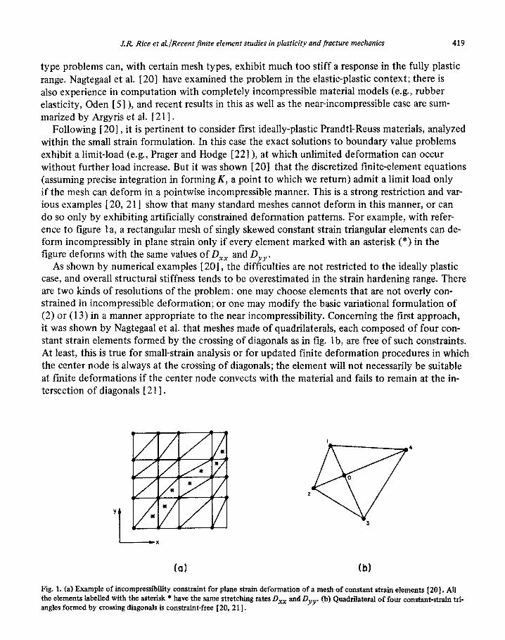
type problems can, with certain mesh types, exhibit much too stiff a response in the fully plastic range. Nagtegaal et al. [ZO] have examined the problem in the elastic-plastic context; there is also experience in computation with completely incompressible material models (e.g., rubber elasticity, Oden [ 5 ] ), and recent results in this as well as the near-incompressible case are sum- marized by Argyris et al. [ 2 1 I .
Following [ 201, it is pertinent to consider first ideally-plastic Prandtl-Reuss materials, analyzed within the small strain formulation. In this case the exact solutions to boundary value problems exhibit a limit-load (e.g., Prager and Hodge [ 22]), at which unlimited deformation can occur without further load increase. But it was shown [ 201 that the discretized finite-element equations (assuming precise integration in forming K, a point to which we return) admit a limit load only if the mesh can deform in a pointwise incompressible manner. This is a strong restriction and var- ious examples f 20, 2 1) show that many standard meshes cannot deform in this manner, or can do so only by exhibiting artificially constrained deformation patterns. For example, with refer- ence to figure la, a rectangular mesh of singly skewed constant strain triangular elements can de- form incompressibly in plane strain only if every element marked with an asterisk (*) in the figure deforms with the same values of DX, and D,,, .
As shown by numerical examples 1201, the difficulties are not restricted to the ideally plastic case, and overall structural stiffness tends to be overestimated in the strain hardening range. There are two kinds of resolutions of the problem: one may choose elements that are not overly con- strained in incompressible deformation; or one may modify the basic variational formulation of (2) or (13) in a manner appropriate to the near incompressibility. Concerning the first approach, it was shown by NagtegaaI et al. that meshes made of quadrilaterals, each composed of four con- stant strain elements formed by the crossing of diagonals as in fig. lb, are free of such constraints. At least, this is true for small-strain analysis or for updated finite deformation procedures in which the center node is always at the crossing of diagonals; the element will not necessarily be suitable at finite deformations if the center node convects with the material and fails to remain at the in- tersection of diagonals [ 2 1 I.
w 4
0
2
Y
I
3
i-x
(a) (b)
Fig. 1. (a) Example of ~compre~ibi~ty constraint for plane strain deformation of a mesh of constant strain elements 1201. AH the elements labelled with the asterisk * have the same stretching rates DXX and ‘)uv 04 Quadrilateral of four constant-strain tri- angles formed by crossing diagonals is constraint-free [20, 211.

Table 1. Evaluation of plane strain elements for use with incompressible or nearly incom- pressible material models, from [ 201. The last column gives the ratio N/C of degrees of freedom to incompressibility constraints for indefinitely extended meshes of the element types shown.
/ Ratio 1 Ratio
I Element Type Constraints 1 Nodes IDeg.Freedo Element 1 Elements IConstraint
_a constant strain triangle
1 112 1
la h-node quadrilateral
Ii Lb.
linear strain
i? triangle 3 2 413
K-7 8-node quadrilateral 1 6 to 8 1 3 / 1 to 3/4
A more general procedure to evaluate the suitability of a mesh of, e.g., some indefinitely ex- tended array of a given element type is to determine the ratio n/c, where II is the number of de- grees of freedom per element in the assembled mesh and c is the number of constraint equations per element necessary to enforce incompressibility. If n/c > I the mesh is suitable, but not other- wise. Table 1, adapted from [201, shows the ratio n/c as its last column for a variety of elements for plane strain analysis. The ratio for constant strain triangles increases to 4/3 when these are arranged as in figure 1 b, since one of the incompressibility constraints for the element array be- comes irrelevant in that case.
A more versatile approach, applicable e.g. with elements such as the four-noded quadriIatera1 in table 1 that have inadequate R/C ratios, is to found the unite-element equations on a modified variational principle given by Nagtegaal et al. [20] and analogous to that of Key [23] for elastic materials. The idea is to let displacement rates X define only the deviatoric part of D, i.e..
D’ = 3 [(ax/&~) + (&+/ax)’ ] ~- 1 tr(G/ax), (30)
and then to regard k and the dilation rate Cp as independently varied parameters related in a Lagrange multiplier sense. For example, the small strain formulation based on (13) becomes, in
materials for which tr b = 3~ trD (where K is a bulk modulus),
s {[ci’ : 6D’ + Kq%(tr &?/‘&x)] + fc(tr &x!/ax - t&l&j} dV= j=& * Sit dV + j“* 6;i: dS (311 V V s
for arbitrary S$ and 6X, with associated 6D’. In fact this principle, as well as its generalization to arbitrary deformations 2201 by modification of (3 1) in the spirit of (2), can be put in the form

J.R. Rice et al/Recent finite element studies in plasticity and fracture mechanics 421
6 (functional of i and c$) = 0 when the forcing rates are fully prescribed or conservative in origin and when t*’ : 6D’ (or 4’ : 6D’ in the small strain formulation) can be written as SU(D’) for some scalar “rate potential” C&D’); such a rate potential does exist when we adopt the form of the Prandtl-Reuss equations given previously. . Plainly, the variational expression (3 1) when implemented for a continuum implies that
4 = tr(&/ax), and when this is substituted into (3 l), (3 1) reduces to (13). In a similar manner, when the variational principle is implemented within the finite-element scheme, it is possible to solve universally for 4 in terms of the nodal displacement rates. This is done by requiring that the adopted interpolations of 6 (not necessarily continuous at element boundaries) and i satisfy that portion of (3 1) which follows from arbitrary Si:
SK&id V = JKtr(ai/ax)&jd V. V V
(32)
As discussed in [ 201, the guideline to choice of an interpolation for 4 can be phrased in terms of the reduction of incompressibility constraints that is necessary to make a given element type suitable from the standpoint of the n/c ratio. Thus, for example, in the case of 4-noded quadri- lateral elements as in the 2nd line of table 1, and also for their 3-D generalization as 8-noded “bricks”, it suffices to interpolate @ as a constant within each element. Hence, the last equation gives, when K is uniform,
6 = $tr(ax/ax)dV= (tlBiijdV)ti,, V V
where now the integration extends over a given element and defines 6 within that element. When this expression for 6 is substituted into (3 1) and the regular finite element procedure is imple- mented, we obtain overall stiffness equations identical to (17), or to (26) in the formulation for arbitrary deformations, but with the expression (18) for K changed to
K= _/-$:L :BdV. V
(34)
Here the effective strain-displacement matrix 5 is given within each element by
Biik = Bijk - f GiiBppk + f 6ii f SB,,, dV. V
(35)
That is, the deformation rate fi defined by i. zi reproduces precisely the deviatoric part of D but does so for its volumetric part only in a volume average sense, uniform within each element. The modified variational principle when implemented for the type of element considered is therefore Equivalent to an ordinary finite element formulation, but based on a strain-displacement matrix B which effectively finds the volume average dilation in each element and uses this as the uniform dilation for the element.

422 J.R. Rice et al./Recmt finite element studies in plasticity ard fracttrw ttlwhutlir,\
25 QNET
=o 20
CONSTANT DILATATION ISOPARAMETRICS
OOON ’ I I I I I
5 6 7 8 9 IO
E6/uo W
Fig. 2. Net section stress versus displacement for plane strain tensile loading of an ideally plastic bar with deep external cracks. Regular 4-noded isoparametric elements overestimate stiffness; “constant dilation” isoparametric elements refer to those used in the procedure of Nagtegaal et al. [ZO] for nearly incon~pressible materials.
Indeed, we have recently noted that the dilation at the center of a 4-noded plain strain quadri- lateral in isoparametric coordinates is in fact the volume-average dilation for that element. Thus, the above approach can be implemented efficiently in the plain strain quadrilateral by using the center dilation as the uniform dilation, i.e., giij equals Biii at the element center. This is entirely equivalent to Hughes’ [ 241 under-integration method for nearly incompressible problems, as used
earlier in a more ad hoc manner by Fried [ 251 and Naylor [ 261. Indeed, for the general axis- symmetric quadrilateral no point can generally be found for which the local dilation is equal to the volume-average dilation for the element. Thus averaging the dilation over integration stations as in the procedure of Nagtegaal et al. 1201 would seem to be the most straightforward technique.
Figure 2, taken from [ 203 , shows the small-strain solution for net stress, (INET. versus end-to-end displacement, 6, for the plane strain tensile loading of an ideally plastic bar with deep double edge cracks. Solutions were carried out for two identical meshes of isoparametric (4-noded quadri- lateral) elements. One mesh used regular elements, i.e., with no special provisions for near-incom- pressible deformation, and gave a load-displacement curve that is badly in error in the fully plastic range, rising well above the theoretical limit load of uNET= (2 + ~)0,/44 = 2.97 u0 as shown in figure 2. (Here CJ~ is the tensile yield stress.) The other mesh used the “constant dilation” scheme within each element, as outlined above, and is seen to give very reasonable results in relation to the theoretical limit load.
For fully plastic analysis of materials which are modelled as completely incompressible, an ef- fective although specialized analysis procedure has been developed by Needfeman and Shill 1271. This is intended for 2-D meshes of quadrilaterals of the type in figure lb, and in which the quadri- laterals extend in strips from one boundary (possibly internal) to another of the body. The direct elimination of nodal displacements to enforce the incompressibility constraint can then be im- plemented efficiently in formulation of the stiffness matrix. Once a convergent solution for u and

AR. Rice et al. /Recent finite element studies in plasticity and fracture rne~ha~ic~ 423
hence for the deviatoric stresses u’ is determined, tra is obtained in their method by direct appli- cation of the virtual work principle. For general meshes which are capable of deforming incom- pressibly, a similar determination and imposition of appropriate constraint equations is possible in principle, and Argyris et al. 1281 discuss the formulation of the constrained stiffness equations. However, these authors caution that in the general case, unexpected linear dependencies between constraints may arise. For example, it is just a linear dependency of this kind which makes the quadrilateral of constant-strain elements, arranged as in fig. lb, suitable for incompressible solids, whereas general constant-strain element meshes are not [ 20, 21 I.
5. Elastic-plastic crack mechanics
Rice has given a recent review of elastic-plastic fracture mechanics [ 29 ] and also a discussion of some problem areas for which finite-element solutions seem well-suited to aiding the develop- ment of crack growth criteria [ 301. Here we restrict ourselves to a discussion of plane strain crack tip deformation fields due to monotonically increasing tensile (Mode I) opening loads. The aim of the studies is to contribute to the understanding of the onset of crack growth, and of the process of stable crack growth, in ductile structural metals.
As background for the computational results to be reviewed in subsequent sections, we men- tion the following points which have emerged from various analytical and nume~cal studies on elastic-plastic fields at a plane strain crack tip (e.g., reviewed in [29] and based on work in [3lL43, 17, IS]):
(i) For an elastic-ideally-plastic material undergoing contained plastic yielding at a crack tip, the limiting stress distribution as r + 0 (r is distance from the crack tip) is, according to analyses within the small strain fo~ulation, identical to that given by the Prandtl field of slip lines, figure 3. (In figure 3, r0 is the yield strength in shear; r0 = o,/fi) This result is suggested by asymptotic studies of the crack tip field [ 33, 35-37, 171 and confirmed by various numerical solutions 139, 17, 18,421. Notable features of the field are that stresses ahead of the crack are elevated well above the yield level in uniaxial tension and that plastic strains, while bounded di- rectly ahead of the tip, become singular within the centered fan regions where slip lines focus. The near-tip details are modified by actual large geometry change effects [38], as will be dis- cussed subsequently.
Within the centered fan sectors the shear strain e,, becomes unbounded in the form, for monotonic loading of a stationary crack,
(here F(0) is a function which must be determined by a full solution) and the associated displace- ment field is such that there is a discrete opening displacement, 6,, between upper and lower crack surfaces at the tip. Details of the crack tip shape on the scale of 6, can be resolved only by appeal to the large geometry change analysis.
In contrast to the situation for contained yielding, the near tip fields of stress and strain asso- ciated with fully plastic, plane strain limit-load solutions for ideally plastic materials are strongly variable from one specimen geometry to another [ 3 1, 40,43 I. Slip line fields for bending and

424 J.R. Rice et al/Recent finite element studies in plasticity and fracture lncclranics
ib)
Fig. 3. Prandtl slip line construction provides the limiting
stress state as r - 0 for contained plane strain yielding of an
ideally plastic material.
Fig. 4. Fully plastic plane strain slip line fields for: (a) cdge-
cracked bar in bending, (b) center-cracked bar in tension.
center-cracked tension geometries are shown in figure 4. The edge-cracked bar subjected to bend-
ing has a near tip stress state very similar to that of the Prandtl field in figure 3, but deformations
concentrate along a single slip line emanating from the crack tip. The center-cracked bar in plane strain tension has a stress field of very much reduced triaxiality in comparison to that of the Prandtl field, the maximum stress ahead of the crack is 1.15 o0 rather than 2.97 uO. Also, defor- mations concentrate along slip lines emanating from the tip at +45” as shown. Yet another ex-
ample is provided by the tensile bar with deep double edge cracks, shown in the insert in figure 2. This has the Prandtl field as its stress state adjacent to the crack tip and, in contrast to the other
two cases, distributed plastic straining with a l/r singularity continues within the fan region at limit load.
(ii) When the material is modelled as strain-hardening in the plastic range according to a power law (i.e., T - y f or p ure shear, where T is shear stress and y shear strain), solutions within the small strain formulation exhibit characteristic “HRR” (references [35, 361 ) stress and strain sin- gularities of the type
eii + r -ll(l+N)~ji(e)’ uii + r -Nl(l ‘N’Gii(@, (37)
and the separation 6 of upper and lower crack surfaces very near the tip varies in proportion to #vI(‘+N). The f unctions Fii(e) and Gii(0) are determined apart from a multiplicative amplitude factor, which can be determined in terms of the crack tip J integral; see next topic. Now, in con- trast to the ideally plastic case, the characteristic singular fields are thought to be valid at the crack tip, again within the small strain formulation, irrespective of the extent of plastic yielding.
(iii) Within the approximation of the “deformation” theory of plasticity (e.g., a theory in which (I is considered to be the function of E that would be obtained by integration of (lo), with D = i, for proportional stress increase) it is possible to characterize the severity of the crack tip field in terms of the J integral 133, 341. This is defined in terms of a contour r which begins on the lower crack surface and ends on the upper, and is

J.R. Rice et al. IRecent finite element studies in plasticity and fracture mechanics 425
J = Jwwn, -n*a~au/ax,lds, (38)
where ds is arc length, n is the outer unit normal to r, u denotes the field of displacement for pur- poses of this discussion, x1 is the direction of (incipient) crack growth, and
W(a) = joiideii 0
(39)
is considered to be a deformation-path independent function of E, consistent with the deforma- tion-plasticity (like non-linear elasticity) constitutive model adopted. For deformations of arbi-
trary magnitude [45], u should be replaced by nominal stress C, r and n measured off in the un-
strained reference configuration, xi replaced by Xi and W interpreted as the stress working per unit reference volume.
The integral is path independent and thus if I’ is shrunk onto the crack tip, J can be interpreted
as some integrated measure of the strength of the crack tip singularity. Thus, the amplitude fac-
tor for the HRR singular fields above can be expressed in terms of J and lead to the forms [35, 361
gij (0 ; N), (40)
where r. is the yield strength in shear, G is the elastic shear modulus, and fij, gij are certain uni-
versal dimensionless functions of 8, dependent on the hardening exponent N as a parameter. In the limit N + 0, corresponding to ideal plasticity, gij corresponds to a stress distribution identical to that of the Prandtl field in figure 3.
Since J is path independent, for cases of contained yielding the integral can be carried out re- mote from the crack tip in material that is still elastic. Indeed, in the limit when the yield zone is small in size compared to crack length and other dimensions of the body (i.e., the “small scale yielding” limit), J has the same value as for a purely elastic material, and this is [ 33, 341
J = (1 - v2)K2/E, (41)
where K is the Irwin-Williams elastic stress intensity factor, defined so that on 8 = 0, uee + (2rrr)-l/’ K as r + 0 according to the linear elastic solution. For larger scale yielding, various methods for determining J can be based on its compliance interpretation, as discussed in a subse- quent section.
To the extent that the J-characterized singular fields as in (40) actually exist and dominate the total deformation field over size scales comparable to those over which fracture micro-mechanics

426 JR. Rice et ul.~Re~~~i finite element studies in plasticity und~ract~r~, t?l~,~~ar~irs
are active, a criterion for the onset of crack growth can be phrased in terms of the attainment ot’
a critical value of J. The approach has been discussed widely in the recent experimental literature
(e.g., [46--481) and is generally considered to be valid provided that certain minimum specimen dimensions are exceeded. It is i~nportant to determine the limits of such a cl~aractcrizati~)Il of the
onset of growth and the following paragraph as well as the next section will give some results on
this. (iv) A variety of finite-element studies have been carried out [ 39, 17, 18.42 I within the small
strain formulation to check and amplify the results noted above. These have etnployed elements
adjacent to the crack tip which were capable of duplicati~lg singular strain behavior of the antic- ipated dependence on r, although the solutions were for the most part carried out before the prob-
lems associated with nearly incompressible material’s response were identified and resolved. The
main concern of published solutions has been with the small scale yielding limit, in which the crack is viewed as semi-infinite with asymptotic approach to the characteristic Irwin-Williams
field at large Y. In practice, the elastic field is imposed along a circular arc of radius large com-
pared to the maximum extent attained by the plastic zone. We take the work of Tracey I1 8 I. as
modified and re-interpreted in some details by Parks 1421, as representing the most definitive 01
this type of analysis. First, within the small strain formulation, J is found to be effectively path independent within the plastic zone. Its values for contours passing through the singular elements at the crack were found by Tracey [ 1 S] to range from 96 to 98% of the far-field value? effectively (411, for hardening exponents N = 0.1 to 0.3. Tracey reported a value of 80% at the tip for his
ideally plastic case (N = 0). But a different near tip element was used in that case and Parks 1471
found a comparable loss in value of J at the tip when the same element was used in a numerical solution for deformation plasticity theory, in which case J should be rigorously path independent.
This implicates the element and suggests, in accord with many other studies (e.g.. [491), that .I is very close to path independent, at least within the small strain fornlL]latiotl.
Many other details of the crack tip field are available. For example, figure 5 from Tracey [ 181
shows the tensile stress directly ahead of the crack tip versus distance from the tip for small scale yielding. In this case Q~,,,,/o, is a function of x/(K/o,)*. The solid curves represent the finite element results, whereas the dashed curves with which they seem to agree asymptotically as Y + 0 are the HRR predictions of (40).
The elastic-plastic boundary for small scale yielding is found to have a “butterfly” shape. For the ideally plastic case Rice and Tracey [ 171 report a maximum plastic zone radius, T~,,,~~~, and plastic zone radius directly ahead of the tip, rp,O, of
(42)
The maximum radius occurs at 8 * 7 1”. Larsson and Carlsson [41] show that solutions for vari- ous specimen configurations may deviate rapidly from this small scale yielding solution, even at K levels well below the limits set by ASTM standard procedures for determining consistent experi- mental K values. These workers show that a two term characterization, in terms of K and the second term in the Irwin-Williams series, representing a uniform stress acting parallel to the crack at its tip, can resolve the difficulty.
Rice and Tracey [ 171 also give an expression for the crack tip opening displacement, but it is now thought, based on the studies by Parks [42], that this value may be low by approximately

JR. Rice et al./Recent finite element studies in plasticity and fracture mechanics 421
01 I I I I I
0 0.01 0.02 0.03 0.04 0.05
X/(K/uo12
(0) (b)
Fig. 6. Slip line constructions for fields near a progressively blunting crack. The fan C of fig. 3 becomes non-centered and focuses into regions D as shown. (a) Smoothly blunting tip as analyzed by Rice and Johnson [38]. (b) Blunting with vertices retained on notch root (McClintock [40] and McMeeking [44] ).
Fig. 5. Stress state near a plane strain crack tip for small scale yielding (from Tracey [ 181, based on small strain for- mulation). The solid curves are based on Tracey’s finite ele- ment solutions with singular crack tip elements. Results are shown for several values of the hardening exponent N in the power law relation r = -yN in the plastic range. Dashed lines represent the HRR singularity ([35, 361 and eqs. 40) as plotted in [ 381.
20% and hence the best estimate of 6, for the ideally plastic case is
6, = 0.59 K=/Eo, = 0.65 J/o, (43)
for small scale yielding. Rice [43] evaluates ds, and dJ in terms of increments of load-point dis- placement from slip line solutions for the various fully plastic cases shown in figures 2 and 4, and finds values of dG,/d(J/o,) of 0.67,0.5 1, and 0.87 for the tension specimen with deep double edge cracks (figure 2) bend specimen (figure 4a), and center-cracked tension specimen (figure 4b), respectively. On the other hand, if strain hardening is considered and is strong enough to give a one-parameter type of near tip field, there should be a unique relation between S, (appropriately defined; see [ 18, 50, 5 1 I > and J/o,, irrespective of specimen type and extent of yielding.
(v) Solutions obtained within the small strain formulation suggest a finite opening of the crack at its tip and unbounded strains. To fully resolve the crack tip field on the scale of 6,, it is neces- sary to do a finite strain analysis. Further, the scale involved is a very small fraction of the maxi- mum extent of the plastic zone. For example, from (42) and (43), S, = 4(o,/E)r,,,,, which is typically on the order of 1% of rp,max. This small size of 6, means that great care must be taken in mesh layout to obtain an accurate finite element solution. On the other hand, it is precisely the smallness of tit/rp,,_ which makes possible the approximate analysis of large tip opening by Rice and Johnson [381 on the basis of slip line theory. Essentially, the result is that the near tip Prandtl field of figure 3 becomes slightly non-centered at the tip so that locally, over the size scale of 6,, the field looks like that in figure 6a or 6b. The crack tip shape is non-unique and solu- tions can be found to the slip line equations corresponding to a variety of geometrical shapes, as noted by McClintock [dol. For example, Rice and Johnson [38] obtained a solution for the

428 J. R. Rice et al./Rectn t jinite eletnen t siudies in plusticitv and fracture rm~ckanic~~
smoothly blunted shape as in figure 6a, and McMeeking [44J has recently presented solutions fol shapes with vertices as in rib. The latter type of solution involves the motion ol‘ originally interior points of the body to the surface and defor~nation kinematics of this type cannot bc l~a~~~llcd readily by finite elements.
There are two main effects of the large, local crack tip geometry changes. I;irst, the stress tri-
axiality necessary to the significant elevation of stresses above uO, as in figures 3 or S, cannot be maintained, and there is, effectively, a maximum concentrated stress level which can be achieved
in the material. Second. the non-centering of the Prandtt fans serves to focus dcforrnatioI1 in- crements into the zone directly ahead of the crack, so that the regions marked D in figure h under-
go very large strains, of order unity. Indeed, it is known from many experimental studies (e.g.. summarized in [29] and [ 511 that the onset of ductile crack growth by the microvoid mechanism
can generally be explained as the attainment of a condition whereby the large strain region D has grown to a size comparable to the spacing of the void-nucleating particles. Thus, for the ductile
crack growth process to be characterized by J, it is generally to be expected that the stress and de- formation fields over size scales comparable to 6, should correlate with ./.
6. Finite element analysis of large plastic opening at a crack tip
According to the previous section, an analysis of the finite strain region at a crack tip is neccs- sary to establish limits for validity of the J-integral crack growth criterion, and also to describe the mechanical environment in which ductile fracture processes take place.
McMeeking 1.5 11 addressed this near tip finite strain analysis for the small scale yielding case by using the very fine mesh of 4-noded q~~ad~lateral isoparanletric elements shown in figure 7. The finite element method was formulated as described earlier for deformations of arbitrary magnitude. using the Prandtl-Reuss material model of equations (1 1) and (12). Further, the modified varia- tional principle of Nagtegaal et al. [ 201 was used to allow for nearly incompressible material rc- sponse, i.e., the constitutive portion, K, of the overall stiffness (equation 2 1) was formed accord- ing to the method of equations (34) and (35).
In order to allow a maximum concentration of elements in the plastic region. Tracey’s 118 1
solutions for small scale yielding. based on the small strain formulation, were used in a manner described more fully by McMeeking [ 5 1 ] to set displacement boundary conditions on the outer radius in figure 7. In this way Tracey’s displacement results even well into his plastic zones could be used for boundary conditions. As long as the perturbations due to finite strains in crack tip blunting are contained in a region well inside the outer radius of McMeeking’s mesh (recall the
smallness of 6 t/~p,,nax ) the solution obtained is valid for small scale yielding. The McMeeking calculations began with a finite crack radius as shown in figure 7. and the
crack was opened up near the tip to at least 5 times its original opening in the various cases analyzed. When the crack tip opening was more than double the original opening, the solutions for colltinllil~g load increments were found to settle down to a steady state in which incrertlents of all quantities with length dimensions (e.g., crack tip opening, plastic zone size) scaled with in- crements of J/a,, where ,I is computed on contours remote from the tip. That is. the solution ap- peared to become independent of the initial root radius size, and this observation enabled McMeeking [ 5 1) to interpret and plot results so as to represent the solution for an initially sharp

J.R. Rice et al./Recent finite element studies in plasticiiy and fracture mechanics 429
SECTION A
SECTION B
Fig. 7. Undeformed configuration of finite element mesh for large strain anatysis of crack tip blunting by Mc~eeking [ 5 11 Section B fits within A, and boundary conditions based on [17, 181 are applied at the outer radius of A.
5
4
?
Qpo
- STRESS u&/u0
---- PLASTIC STRAIN
,6=0
N = 0.1 k?= 0 (FROM SLIP LINE SOLUTION
t \ BY RICE 8 JOHNSON)
IL.
25
.20
.I5
cp
.I0
.05
0 0 2 4 6 8 IO
R/b
Fig. 8. Result from McMeeking’s [5 11 fmite strain analysis of crack tip blunting: “true” stress CQ@ and equivalent plastic tensile strain P near the crack tip for power-law hardening material with N = 0.1 and UO/E = l/300. Distance R is mea- sured from the tip in the undeformed state; b is the current opening of the originally semi-circular crack tip, and has in- creased by a factor of 5 or more in the calculation. Strain dis- tributions agree well with those of Rice and Johnson [ 381.
crack. The obvious difficulties in starting the calculation with an initially sharp tip could thus be avoided.
McMeeking reported crack tip shapes which were similar to those found by Rice and Johnson [ 381 based on slip line theory and corresponding to the smooth type solution shown schematically in figure 6~. Recall that a solution of the type in figure 6b cannot be duplicated by finite elements.
For the case E/u0 = 300, N = 0.1, the true stress uo8 and equivalent tensile plastic strain ?’ from the finite element results near the blunted crack tip have been plotted in figure 8 against dis- tance (measured in the undefo~ed state) from the crack tip. Distance has been normalized by b, which as indicated by the insert, is effectively a measure of the crack tip opening. It corresponds to the displacement of the point at the top of the semi-circular crack tip in figure 7. The results from many of the later increments of the calculation, after attainment of steady state, were plotted, and the smooth curves in figure 8 could be drawn through them. Far from the tip, the

430 J.R. Rice et al./Rwent finite dernent studies in plasticity und fracture t?rwhanks
stresses agree with the small scale yielding results of Tracey [ 18 1. As in Tracey’s results. figure 5. the stress rises due to increasing triaxial constraint as the tip is approached. But the triaxiaiity is
limited by the free surface of the crack, so that the stresses fall off towards the crack tip. an of-
feet noted in [381. The result is the peak of the uoB stress in figure 8, which coincides with a tnaxinlum for the triaxial stress. That the stress elevation near the tip is indeed caused much more
by triaxiality than by hardening can be seen from the rather small equivalent plastic strains around
Y = 2h. The equivalent plastic strain is high only very close to the tip surface where the openins
must be ac~o~nmodated by stretching. This does lead to elevation of flow stress, but so ~10s~ tr)
the tip that there is no significant effect at the centroids of the elements nearest the tip when N = 0.1. It should be noted that if the flow stress 0 eventually saturates to a constant value at large strain, then the upturn of stress near the tip could reach only limited levels. The results I5 1 -I
for stress and plastic strain in the other cases E/o0 = 300, N = 0 and N = 0.2 and E/o0 = 100.
N = 0 are similar to those plotted in figure 8 with peak stresses increasing and lying closer to the
tip (in terms of R/b) with increasing N The peak stress uoO on .Y = 0 in both cases with :V = 0 is
approximately 30, as predicted from slip line theory, figures 3 and 6. Plotted against R/h. the equivalent plastic strains are almost independent of material properties for the range of uO/l:‘ and N considered, and agree reasonably well with the slip line predictions of Rice and Johnson I38 1
for a non-hardening material. This means that the strain-based approximation for hardening mate- rials developed by Rice and Johnson is relatively accurate, especially considering how inexpensive it is to calculate.
As suggested earlier, the crack tip opening displacement rises linearly with the value of ,1/o, computed on a remote contour in the su~oLlnding elastic field. The coefficient in the linear rcla- tionship is the proportionality constant for the opening, 6,, of an initially sharp crack. in view of the insignificance of the original tip shape to the later results. There is, however, ;I degree of am- biguity in the exact value of the crack tip opening displacemen& which is illustrated by the curved
tip shape shown in the insert of figure 8. An appropriate definition might be the opening at the
point half an opening back from the very tip of the crack. Using this definition. the results for the
crack tip opening of an initially sharp crack conform well to
6, = 0.58 to 0.65 Jfuf&, (441
where, fotlowing Rice’s [431 suggestion for unifying the results
~fknv = 0 ,/!? N N ..___I_ -
@ -1 2(1 + V) (1 +N)o()/E . (45)
The 0.58 applied to the lower strength material with E/u0 = 300 and 0.65 arises for the higher strength material with E/a0 = 100.
Path integral calculations of J on contours partly in the crack tip plastic zone of the finite ele- ment calculations indicate that J is path independent where the plastic strains are small. Close to the tip, on contours less than about 4b from tip in the undeformed configuration, there is quite strong path dependence of J. This is illustrated in figure 9 where contour values of J, normalized by J_ (the remote J value), are plotted against a distance representative of how far the contours are from the tip. The results seem to indicate that J + 0 as R + 0, a situation that also arises near

JR. Rice et &/Recent finite element studies in plasticity and fracture mechanics 431
0
0.2 y I +
CONTOUR FOR ,’ CALCULATION
I’ :
OF J. (R IS THE
: : REPRESENTATIVE
_------- b ---+-THE CONTOUR
-’
‘\ DISTANCE OF
i FROM THE NOT0 : ,’ : TIP WHEN
‘\ /’ UNDEFORMED 1.
‘\ I’ k___/
DEFORMED CRACK SURFACE
0.11 .05
0 I I I I I I I I I I I I
0 I 2 3 4 5 6 7 8 9 IO II I2
R/b
Fig. 9. Plot of I integral ~computed as a contour integral) versus distance of the contour from the tip as measured in the unde- formed state [S 1, 521.
the blunting crack tips of a fully plastic, deeply double edge cracked panel analyzed by the slip line method [ 521. This case has features of triaxiality and intense stretching in a near-tip zone that are similar to the situation in small scale yielding. The path dependence in both cases seems to arise from the severe non-proportionality of straining that occurs in the near-tip zone. The zone of significant path dependence for small scale yielding lies within a radius of approximately
12(001E)5,,maX where Y~,,,.,~~ of (42) is the maximum plastic zone extent. This radius typically lies between 2 and 10% of rp,max, and the effect seems to be detectable only when the significantly non-proportional straining paths associated with finite geometry changes are incorporated in the analysis. Thus, J is effectively path independent in the region within which small strain theory applies, and its value on contours of radius greater than some small fraction of rp,mox seems to provide a characterization of the near tip field.
We have commented on the question of whether a field similar to that for small scale yielding, and parameterized in terms of J, continues to exist near the crack at large scale yielding. For example, the slip line solutions shown in figure 4 suggest that such will not be the case within the non-hardening idealization. As remarked, the relevant size scale over which a J-characterized field must dominate will typically be of the same order as the size of 6, at the onset of ductile crack growth. Thus, it is appropriate to examine the finite deformation zone very near the crack tip to resolve the issue. This has recently been done by McMeeking and Parks [ 531, who apply the finite element techniques mentioned previously to edge-cracked bend (ECB) and center-cracked panel (CCP) plane strain geometries, i.e., the same geometries as in figure 4.
McMeeking and Parks [ 53 1 note that if J is to characterize the near tip field, then the stress and strain distributions very near the crack should be identical to those for the McMeeking [ 5 1 ] small scale yielding solution, when distance is plotted in terms of ~~(J/u~) in all cases. McMeeking

432 J.R. Rice et aLlRecent finite element studies in plasticity and fracture mechaks
‘- IECB o/w = 0.9 N = 0.1 j ??
, 0,/E = l/300 / EU
Fig. 10. Stress directly ahead of crack and equivalent plastic strain along line at 45” with tip, for fully plastic, finite deformation analysis by McMeekmg and Parks [ 531 of edge-cracked bar (fig. 4a) in plane strain bending. The solid and dashed lines show the corresponding results, with distance normalized in all cases by J/GO, for small scale yielding.
and Parks used a mesh which also had an initially semicircular notch root of diameter L/5000, where L is the untracked ligament dimension in figure 4; L =: w - a. In results to be shown the specimen was deformed sufficiently to increase this diameter at the crack tip by factors in excess of 25. Their results for stress oYY directly ahead of the crack and equivalent plastic strain $’ along a line at 45” with the crack line are shown in figure 10 for a deeply edge-cracked bar in plane strain bending. The material has o,/E = l/300 and N = 0.1. All the numerical data shown by the points (open for stress, solid for strain j corresponds to the fully yielded range. The solid and dashed curves are the corresponding results from the McMeeking [ 5 1 I small scale yielding solu-
cr,Y
cr, 5- CCP o/w: 0.5 N = 0.1 CCP o/w = 0.5 N = 0.1
Q’E = l/300
-SMALL SCALE YIELDING
L___.i _. ._.___“-_i__
0 I 2 3 4 0 I 2 3 4
R/(J/CT,) R/(J/(&)
Fig. 11. Stress directly ahead of crack tip for centercracked panel (fig. 4b) in plane strain tension (from f 5 3 ] 1. Solid curve for small scale yielding.
Fig. 12. Strain along 4.5” line from tip for center-cracked panel in plane strain tension (from (531). Curve shows result for small scale yielding.

J. R. Rice et al./Recent finite element studies in plasticity and fracture mechanics 433
tion. The agreement with them is very good, and the results would seem to support the use of J as a unique crack tip characterizing parameter over a wide range of yielding conditions in this case.
On the other hand, as suggested by the comparison of the slip line field in figure 4b with that of figures 4a and 3, the situation is found to be very much different for the center-cracked panel subject to tensile loading. The stress distribution at various J levels (the last of which just corre- sponds to the onset of general yielding of the ligament) is shown in figure 11 and the strain in figure 12. In this case it is seen that already at well-contained yielding there are noticeable differ- ences in the (T,,,, distribution and also, although smaller, in that for ?’ . Thus, in this case the re- strictions on specimen size for correlation of the onset of crack growth in terms of J are very much more stringent than for the bend specimen.
7. Virtual crack extension for determination of J
As we have seen, within certain limits the J integral provides a one-parameter characterization of the near tip field, and a criterion for the onset of crack growth can be phrased in terms of it. Thus it is important to develop techniques for efficient determination of J, not only for the usual 2-D idealizations of test specimens but for the 3-D crack configurations of actual test specimens and flaws in structural components.
In two-dimensional planar configurations, the contour integral definition of J, eq. (38) can be readily computed from the results of finite element solutions. The effective path independence permits the evaluation on a contour (or contours) remote from the crack tip itself, and accurate results can thus be obtained with reasonably coarse meshes. However, in three-dimensional con- figurations, plane strain conditions are only asymptotically approached at the crack front, so the line integral definition of J may be utilized only very near the tip. In order to obtain sufficiently accurate values of the integrand there, a detailed mesh is necessary, and for three-dimensional problems the prohibitive costs of very fine near crack front meshes render the line integral defini- tion of J unusable.
An alternative approach by Parks [ 54, 551 based on the compliance interpretation of J seems better suited for extensions to efficient three-dimensional analysis. Following [ 54, 551, we present the essentials of the method and discuss some of the results which have been obtained.
For the present, we limit consideration to a cracked planar body of unit thickness and a con- stitutive relationship of the total strain or deformation plasticity theory type (i.e., non-linear elastic), although each limitation will subsequently be relaxed. In such cases, as Rice [34] has shown, the J integral can be interpreted as the negative of the rate of change of “potential energy” a with respect to crack length, 1:
J=-2
load (46)
(n should be regarded as being defined by monotonic loading of a family of bodies that are iden- tical except for crack size, consistent with the deformation plasticity model [ 34,46, 57.1
From any finite element solution for the deformations and stresses in this problem, we can readily construct an approximation to the potential energy as

vr= CJWdV- ut *P(y) = c W(u, y) -. ut P(y) = n(u, y), (37) v
where the summation is over the elements and y is the vector of nodal point coordinates. Note that P and W are dependent ony through the shape functions.
Now consider the virtual crack extension indicated in fig. (13) by incrementing by a small SI the x-coordinates of all nodes on and within an interior contour I’* which surrounds the crack tip. The variation in potential energy which this virtual crack advance occasions is
677 = 6y’ * p an + 6u’ * -- au *
(48)
But because the original finite element solution was at equilibrium, the vector &n”y, zr)/au vanishes, so that regardless of the value of the vector Su’, only the first term in (48) must be re- tained.
Now by (46), 6~ = -J&l so that
(49)
If loading is accomplished other than by body forces or by loads acting on the crack surfaces within the part of the mesh distorted by crack extension, V/ay vanishes and we need only cal- culate changes in W over those elements between contours I’* and r, which are distorted in the virtual crack extension (fig. 13). _ The procedure is simplest to illustrate for meshes of constant strain triangles, in which case
W = WA where A is element area. The functional dependence of A on nodal coordinates y is straightforward to determine. Further,
where B =: B(V) is the strain-displacement matrix. Actual derivatives aA/ay, aB/ay, and aP/ay are cumbersome to form and it is simplest to evaluate them by numerical differencing [ 54, 55 I .
For 3-D configurations in which J may vary along the crack front, the local J value is defined by
tin = - +j- J(s) 6&s) ds, (Sl) crack front
where 61(s) is the local crack front advance associated with the individual sets of nodal perturba- tions. By separately advancing nodes along the crack front, arc-length weighted J values can be computed along a general three-dimensional crack front.
As to the other restriction placed on the development at the outset, deformation plasticity,
J.R. Rice et aLlRecent finite element studies in plasticity and fracture mechanics 435
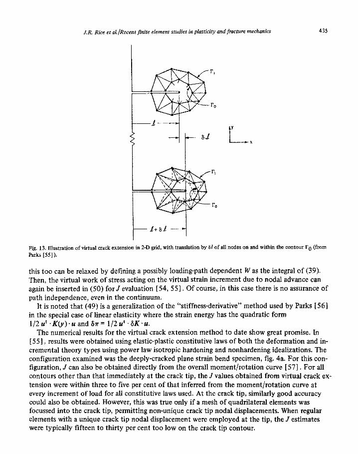
Fig. 13. Illustration of virtual crack extension in 2-D grid, with translation by 61 of all nodes on and within the contour r,-, (from Parks f 551).
this too can be relaxed by defining a possibly loading-path dependent W as the integral of (39). Then, the virtual work of stress acting on the virtual strain increment due to nodal advance can again be inserted in (50) for J evaluation [ 54, 551. Of course, in this case there is no assurance of path independence, even in the continuum.
It is noted that (49) is a generalization of the “stiffness-derivative” method used by Parks [ 561 in the special case of linear elasticity where the strain energy has the quadratic form 1/2u’X(y).uand&r= 1/2u’GX.u.
The numerical results for the virtual crack extension method to date show great promise. In [ 551, results were obtained using elastic-plastic constitutive laws of both the deformation and in- cremental theory types using power law isotropic hardening and nonh~dening idealizations. The configuration examined was the deeply-cracked plane strain bend specimen, fig. 4a. For this con- gyration, J cm also be obtained directly from the overall moment~rotation curve [ 571. For all contours other than that immediately at the crack tip, the J values obtained from virtual crack ex- tension were within three to five per cent of that inferred from the moment~rotation curve at every increment of load for all constitutive laws used. At the crack tip, similarly good accuracy could also be obtained. However, this was true only if a mesh of quad~later~ elements was focussed into the crack tip, permitting non-unique crack tip nodal displacements. When regular elements with a unique crack tip nodal displacement were employed at the tip, the J estimates were typically fifteen to thirty per cent too low on the crack tip contour.

436 J. R. Rice et al./Reccnt finite elemetlt studies in plasticit)’ arld fractuw ttzcxlratzic~s
In [ 541, the method was applied to the plane strain center-cracked panel in incompressibl~~
materials of the pure power law type. Such material models can be used to estimate ./ in the t’uliv plastic range of elastic-plastic materials [58, 591. In the linear elastic case, agreement witli ;~i‘- cepted solutions [6 1 I was within three per cent for all contours. In the mildly nonlinear c;I%‘s examined the maximum difference among the J values computed on the three iontours was eight
per cent, although there was some sensitivity of the results to the convergence criteria cn-
ployed in obtaining the initial nodal displacements U. The J values obtained arc in good agreement
with the recent calculations of Ranaweera and Leckie 1601 and of Hutchinson et al. I59 I Again.
non-unique crack tip fields were employed by using degenerate quadrilateral elements. Although we are unaware of elastic-plastic applications of the method to date in other than
planar configurations, the general framework presented here would seem ideally suited to suc~h
extensions. Indeed, the method was successfully applied in [ 561 to axisymrnetric and threr-di-
mensional problems for linear elastic response.
8. Analysis of stable ductile crack growth and fracture instability
It is typical of many ductile metals that the onset of crack growth is not coincident with a final fracture instability. Instead, cracks are observed to grow in an initially stable manner under in- creasing load (or, depending on the loading arrangement, load-point displacement) until critical conditions are attained. Due to the strain-path dependence of elastic-plastic stress-strain relations. the deformation field near the tip of a growing crack is different from that created by monotonic loading of a stationary crack. Indeed, the phenomenon of stable crack growth seems to arise be- cause of the permanence of plastic deformations, so that it is necessary to continue to deform the material in order to maintain a suitably concentrated strain field at the advancing crack tip.
Stable growth has been discussed in the anti-plane strain context by McClintock and Irwin 13 1 ]
for ideally plastic solids, and analyses of the singular structure of deformation fields near growGng plane-strain tensile cracks have been given by Rice [ 34, 43 I , Cherepanov [ 62 I , and Rice and Sorensen [50]. Due to the difficulties of having a mesh which remains highly focussed at the tip as
the crack grows, finite element solutions for this case (e.g., [49, 50, 63--651) have not yet been nearly so successful as for the stationary crack in contributing to an understanding of the stress and deformation fields very near the tip. Further, given the strongly non-proportional stress his- tory experienced by a material point as the crack passes by, there are as yet unresolved questions as to the adequacy of the Prandtl-Reuss model or, indeed, of any simple classical plasticity model
in describing the actual path of plastic response. Nevertheless, working with the Prandtl-Reuss model as specialized to the ideally plastic, small
strain formulation, the results shown in fig. 14 for the stress history near a growing crack were ob- tained by Sorensen [64]. The mesh is made up of quadrilaterals of constant strain elements of the type in fig. lb, to allow for near incompressibility, and a detail of the mesh near the original crack tip is shown. Analogous to the mesh shown in fig. 7, the overall shape is semi-circular and the diameter of the semi-circle is approximately 26 times the length of the mesh detail shown (or 230 times the side length of the near-tip quadrilaterals). Displacements consistent with the elastic singular term were imposed at the outer radius of the mesh (i.e., the usual small scale yielding for- mulation), and the load versus crack length relation that was imposed is shown at the top of fig. 14.

J.R. Rice et a~~Rece~t finite element studies in plasticity and fracture rnecha~~~~ 437
t
K/K,
- numerical results
--- Prondtl field
22
L- XI
0
‘origin01 crack tip
-I t
Fig. 14. The imposed load versus crack tength history, a near-tip detail of the ~mite~~ement grid, and stress histories in the shaded sub-element for Sorensen’s f64j analysis of plane strain quasi-static crack growth in an ideally plastic materiah There are 5 growth steps of one element each. The stress histories shown by the dashed lines correspond to the Prandtl field of fig. 3. The plastic zone at the onset of the fist growth step has a maximum extent of approximately 7 times the near-tip quadrilateral element edge.
Here K, is the load to bring the most highly stressed sub-element to yield, and the level Ki at which the initial step of crack growth is imposed corresponds to a m~imum plastic zone extent, r p,mox = 0.1 5(Ki/a,>2 by eq. (42), of approximately 7 times the quadrilateral edge length.
The crack growth I - I, has been normalized by this quantity, and each of the total of 5 growth steps imposed corresponds to growth by approximately 14 per cent of the maximum plastic zone dimension at the onset of growth, or by approximately 50 per cent of the radius rp,e of the plastic zone directly in front of the crack. Each step of crack advance has been accom- plished by reducing to zero in 5 equal increments the nodal forces which acted before the crack passed through a given node. Obviously, this is a poor representation of continuous crack growth except at distances from the tip which are large compared to each growth step.
The points connected by solid lines in the lower portion of fig. 14 show the stresses calculated numerically in the shaded sub-element as the crack grows by it. The points connected by dashed lines show the stresses that would have been predicted on the basis of the Prandtl field of fig. 3 if this had moved through the material with the crack tip. We note that the asymptotic arguments [33, 17, 501 leading to the Prandtl field (as the r + 0 limit of the total stress field) seem to be equally valid for growing as for stationary cracks. Thus the results of fig. 14 can be interpreted as being consistent with the notion that the Prandtl field is moving through the material with the growing crack (at least as r + O), although the test is far from definitive because the shaded sub- element is both close enough to the tip to be affected by the discontinuous nature of the crack advance, and sufficiently removed from the tip (recall that rp,max = 7 quadrilateral edges) that it

438 J.R. Rice et al/Recent finite elernrnt studies in plasticit,\’ and fractuw meclzonic.\
may not closely duplicate Y + 0 behavior. As Rice and Sorensen [ 501 comment, it appears thar the issue can be resolved only by solution for a very much finer mesh so that the plastic zone cx- tends over distances on the order of 50 element dimensions as the crack grows.
Rice and Sorensen [ 501, on the basis of earlier work by Rice [34, 43 I and Cherepanov [6X1. present a discussion of the near tip deformation field associated with integration of the Prandtl-
Reuss equations on the assumption that the Prandtl fan zone of fig. 3 moves through the material
with the crack tip. In this way they show, e.g., that the rate of increase of the opening displace- ment 6, between upper and lower crack surfaces, at distance Y from the tip is given in the limit
r-Oby
for simultaneous increase of crack length 1 and remote loadings (assumed to be adequately charac-
terized for contained yielding by the far-field J value). Here /3 = 4(2 - v)/dT = 3.93 for v = 0.3;
the pure number CY and quantity R, having length dimensions, are undetermined by the asymptotic analysis. However, by determining the further increments of near tip nodal displacements for the portions of the loading history in fig. 14 for which K (or J) increases at fixed 1. Sorensen [ 641 is able to determine (Y and finds it to be nearly constant, 7 per cent variation being typical. Rice and Sorensen [ 501 suggest that the parameter R may scale with the extent of the plastic region, and hence be proportional to EJ/aE for small scale yielding. This is not inconsistent with their numeri- cal results but the mesh is too coarse to resolve the issue or, indeed, to provide a definitive check of (52). For fully plastic conditions in a specimen geometry which retains a Prandtl-like field at limit load, it is expected that R would saturate in value to some fraction of the untracked ligament dimension, L, [ 501.
Taking QL as a constant, let us compare the predicted crack opening profile for a stationary versus a growing crack: in the stationary case I= 0 and (52) integrates to
6 = ctJ/uo. (53)
That is, there is a discrete opening displacement near the crack tip and associated with this is the l/r strain singularity discussed earlier, eq. (36). But for a crack which grows as the load is in-
creased, (52) may be integrated to obtain [501
(54)
where e is the natural logarithm base and where r is small, and it is assumed that dJ/dZ and R are sensibly constant for crack advance over distances on the order of r. Note that now there is no dis- crete opening displacement at the crack tip, 6 + 0 as r -+ 0, although the crack profile has a vertical
tangent at the tip. Further, the theoretical analysis predicts a considerably lessened strain concen- tration for a growing crack, with E becoming unbounded in the fan regions as log( 1 /r> rather than as l/r.

J.R. Rice et aLlRecent finite element studies in plasticity and fracture mechanics 439
Equation (54) can serve as a qualitative basis for discussion of stable crack growth if, following [ 501, we tentatively adopt the simple, model criterion that for continuing growth a certain critical opening 6 must be maintained at a fixed distance r = AZ behind the tip. Then (54) gives
6 CYdJ 00 -= Al o. dl
---f$ log (55)
We note that for a sufficiently large opening angle parameter, s/AZ, dJ/dZ must initially be positive to meet the growth criterion. However, as J and the extent of the plastic region increase, it is to be expected that R increases and hence that dJ/dl reduces in value. Two limits may occur: first, if the crack-containing body is large enough, the plastic zone extent and hence R can increase suffi- ciently that dJ/dl will drop in value to zero; then further crack growth will occur at fixed J in what is presumably a steady-state configuration relative to the advancing tip. The second limit is that full plasticity conditions are reached before dJ/dl has reduced to zero. Then it is expected that R saturates in value to some fraction of the ligament dimension, and thus further growth takes place at an effectively constant value of dJ/dl, at least for growth increments which are small compared to the overall ligament size.
These observations seem at least qualitatively consistent with observed behavior, as summarized e.g. in [ 50, 66, 671. Fracture instability occurs when, and if, the dJ/dZ value required for con- tinuing growth falls below the value of dJ/dl that would be enforced by the loading system for an increment dl of growth without a further increment of load, or of load-point displacement, or of whatever “loading” parameter is imposed in the case considered [ 66, 671.
Clearly, the understanding of crack tip behavior is far less developed in the growing crack case than in the stationary case. For example, there is little understanding at present of the effects of strain hardening on the preceding discussion, and even the description for the ideally-plastic model is rather tentative. This is an important area for continuing work, directed toward both the obtaining of more accurate solutions by mesh refinement and the development of new computing techniques. For example, it would be useful to have a finite-element technique which would allow a highly focused mesh to move relative to the material with the advancing crack tip.
Acknowledgment
The studies reviewed here were carried out with support from the U.S. Department of Energy and the NSF Materials Research Laboratory program for the fracture applications, and from the National Aeronautics and Space Administration for the general finite-element formulations. We are grateful to several present and former colleagues at Brown University for useful discussions and contributions, specifically to Drs. H.D. Hibbitt, P.C. Paris, W. Prager, P.V. Marcal, J.C. Nagtegaal, A. Needleman, and D.M. Tracey.

440 J. R. Rice et aLlRecent finite element studies in plasticity and fracture tnccharrics
References
[l] J.H. Argyris, Continua and discontinua, in: Proceedings 1st Conference on Matrix Methods of Structural Mechanics, 1965
(Wright-Patterson Air Force Base, 1967) l-198.
[2] G.G. Pope, A discrete method for analysis of plane elasto-plastic strain problems, Aeron. Q. 17 (1966) 83.
[3] J.L. Swedlow, M.L. Williams and W.H. Yang, Elasto-plastic stresses and strains in cracked plates, in: T. Yokobori et al. (cds.),
Proceedings 1st International Conference on Fracture, Sendai 1965, 1 (Japanese Sot. for Strength and Fracture, Tokyo.
1966) 259-282.
[4] P.V. Marcal and I.P. King, Elastic-plastic analysis of two-dimensional stress systems by the finite-element method, lnt. J.
Mech. Sci. 9 (1967) 143-155.
[5] J.T. Oden, Finite elements of non-linear continua (McGraw-Hill, New York, 1972).
[6] H.D. Hibbitt, P.V. Marcal and J.R. Rice, A finite-element formulation for problems of large strain and large displacement,
Int. J. Solids Structures 6 (1970) 1069-1086.
[7] A. Needleman, A numerical study of necking in circular cylindrical bars, I. Mech. Phys. Solids 20 (1972) 11 I- 127.
[S] A. Needleman, Void growth in an elastic-plastic medium, J. Appl. Mech. 39 (1972) 964-970.
[9] J.R. Osias and J.L. Swedlow, Finite elastoplastic deformation, I. Theory and numerical examples, Int. J. Solids Structures
10 (1974) 321-339.
[lo] R.M. McMeeking and J.R. Rice, Finite clement formulations for problems of large elastic-plastic deformation, Int. J. Solids
Structures 11 (1975) 601-616.
[l I] R. Hill, Some basic principles in the mechanics of solids without a natural time, J. Mech. Phys. Solids 7 (1959) 209-225.
[ 121 W. Prager, An elementary discussion of definitions of stress rate, Q. Appl. Math. 18 (1961) 403-407.
[13] W. Prager, Introduction to mechanics of continua (Ginn, Boston, 1961; Dover, 1973).
[14] R. Hill, On constitutive inequalities for simple materials, J. Mech. Phys. Solids 16 (1968) 2299242, 3155322.
[15] J.W. Hutchinson, Finite strain analysis of elastic-plastic solids and structures, in: R.F. Hartung (ed.), Numerical Solution of
Nonlinear Structural Problems (ASME. New York, 1973) AMD 6, 17-29.
[ 161 R. Hill, The mathematical theory of plasticity (Oxford Univ. Press, 1950).
[17] J.R. Rice and D.M. Tracey, Computational fracture mechanics, in: S.J. Fenves et al. (eds.), Numerical and computer methods
in structural mechanics (Academic Press, New York, 1973) 585-623.
[18] D.M. Tracey, Finite element solutions for c:ack-tip behavior in small-scale yielding, Trans. ASME (Ser. H, J. Eng. Mat. Tech.)
98 (1976) 146-151.
[ 191 J.H. Argyris and D.W. Scharpf, Methods of clastoplastic analysis, ZAMP 23 (1972) 5 17--552.
[20] J.C. Nagtegaal, D.M. Parks and J.R. Rice, On numerically accurate finite element solutions in the fully plastic range, Camp.
Meths. Appl. Mech. Eng. 4 (1974) 1533177.
[21] J.H. Argyris, PC. Dunne, T. Angelopoulos and B. Bichat, Large natural strains and some special difficulties due to non-
linearity and incompressibility in finite elements, Comp. Meths. Appl. Mech. Eng. 4 (1974) 219-278.
1221 W. Prager and P.G. Hodge, Jr., Theory of perfectly plastic solids (Wiley, New York, 1951; Dover, 1968).
[23] S.W. Key, A variational principle for incompressible and nearly-incompressible anisotropic elasticity, Int. J. Solids Structures
5 (1969) 951-964.
[24] T.J.R. Hughes, Equivalence of finite elements for nearly incompressible elasticity, J. Appl. Mcch. 44 (1977) 181-l 83.
[25] I. Fried, Finite-element analysis of incompressible material by residual energy balancing, Int. J. Solids Structures 10 (1974)
99331002.
[26] D.J. Naylor, Stresses in nearly incompressible materials by finite elements with application to the calculation of excess pore
pressures, Int. J. Numer. Meths. Eng. 8 (1974) 4433460.
[27] A. Needleman and C.F. Shih, A finite element method for plane strain deformations of incompressible solids, Comp. Meths.
Appl. Mech. Eng. 13 (1978) 223-240.
[28] J.H. Argyris, P.C. Dunne, Th.L. Johnsen and M. Miller, Linear systems with a large number of sparse constraints with appli-
cation to incompressible materials, Comp. Meths. Appl. Mech. Eng. 10 (1977) 105132.
[29] J.R. Rice, Elastic-plastic fracture mechanics, in: F. Erdogan (ed.), The mechanics of fracture (ASME, New York, 1976) AMD 19,23-53.
[30] J.R. Rice, Some computational problems in elastic-plastic crack mechanics, in: A.R. Luxmoore and D.R.J. Owen (eds.). Numerical methods in fracture mechanics (Dept. Civil Eng., Univ. College of Wales, Swansea, 1978) 434-449.
131 I F.A. McClintock and G.R. Irwin, Plasticity aspects of fracture mechanics, in: Fracture toughness testing and its applications (ASTM, Philadelphia, 1965) STP 381, 84-113.
[32] G.P. Cherepanov, Crack propagation in continuous media, Appl. Math. Mech. (translation of PMM) 3 1 (1967) 4766488.
(331 J.R. Rice, A path-independent integral and the approximate analysis of strain concentration by notches and cracks, J. Appl. Mech. 35 (1968) 379-386.

J.R. Rice et al./Recent finite element studies in plasticity and fracture mechanics 441
[34] J.R. Rice, Mathematical analysis in the mechanics of fracture, in. . H. Liebowitz (ed.), Fracture: an advanced treatise 2 (Aca-
demic Press, New York, 1968) 191-311.
[351
[361
I371 [381
[391
[401
[411
[421
J.W. Hutchinson, Singular behavior at the end of a tensile crack, J. Mech. Phys. Solids 16 (1968) 13-31. J.R. Rice and G.F. Rosengren, Plane strain deformation near a crack tip in a power law hardening material, J. Mech. Phys. Solids 16 (1968) 1-12. J.W. Hutchinson, Plastic stress and strain fields at a crack tip, J. Mech. Phys. Solids 16 (1968) 337-347. J.R. Rice and M.A. Johnson, The role of large crack tip geometry changes in plane strain fracture, in: M.F. Kanninen et al. (eds.), Inelastic behavior of solids (McGraw-Hill, 1970) 641-672. N. Levy, P.V. Marcal, W.J. Ostergren and J.R. Rice, Small scale yielding near a crack in plane strain: a finite element analysis, Int. J. Fracture Mech. 7 (1971) 143-156. F.A. McClintock, Plasticity aspects of fracture, in: H. Liebowitz (ed.), Fracture: an advanced treatise 3 (Academic Press, New York, 1971) 47-225. S.G. Larsson and A.J. Carlsson, Influence of non-singular stress terms and specimen geometry on small scale yielding at crack tips in elastic-plastic materials, J. Mech. Phys. Solids 21 (1973) 263-277. D.M. Parks, Some problems in elastic-plastic finite element analysis of cracks (Ph.D. Dissertation, Brown University, 1975) Ch. 3.
[43] J.R. Rice, Elastic-plastic models for stable crack growth, in: M.J. May (ed.), Mechanics and mechanisms of crack growth: Proceedings of 1973 Conference at Cambridge, England (British Steel Corp., Physical Metallurgy Centre Publication, 1975) 14-39.
(441 R.M. McMeeking, Blunting of a plane strain crack tip into a shape with vertices, Trans. ASME (Ser. H, J. Eng. Mat. Tech.) 99 (1977) 290-297.
[45] J.D. Eshelby, Energy relations and the energy momentum tensor in continuum mechanics, in: M.F. Kanninen et al. (eds.),
Inelastic behavior of solids (McGraw-Hill, 1970) 77-115. [46] J.A. Begley and J.D. Landes, The J integral as a fracture criterion, in: Fracture toughness (ASTM, Philadelphia, 1972) STP
514, l-23. [47] J.A. Begley and J.D. Landes, Test results from J integral studies, an attempt to establish a Jlc test procedure, in: Fracture
analysis (ASTM, Philadelphia, 1974) STP 560. [48] J.A. Begley and J.D. Landes, Serendipity and the J integral, Int. J. Fracture 12 (1976) 764-766. [49] C.F. Shih, H.G. deLorenzi and W.R. Andrews, Studies on crack initiation and stable crack growth, in: Elastic-plastic fracture
(ASTM Philadelphia, 1979) STP 668, in press. [50] J.R. Rice and E.P. Sorensen, Continuing crack tip deformation and fracture for plane strain crack growth in elastic-plastic
solids, J. Mech. Phys. Solids 26 (1978) 163-186. [5 1 I R.M. McMeeking, Finite deformation analysis of crack tip opening in elastic-plastic materials and implications for fracture,
J. Mech. Phys. Solids 25 (1977) 357-381. [52] R.M. McMeeking, Path dependence of the J integral and the role of J as a parameter characterizing the near tip field, in:
Flaw growth and fracture (ASTM, Philadelphia, 1977) STP 631, 28-41. [53] R.M. McMeeking and D.M. Parks, On criteria for J dominance of crack tip fields in large scale yielding, in: Elastic-plastic
fracture (ASTM Philadelphia, 1979) STP 668, in press. [54] D.M. Parks, Virtual crack extension: a general finite element technique for J integral evaluation, in: A.R. Luxmoore and
D.R.J. Owen (eds.), Numerical methods in fracture mechanics (Dept. Civil Eng., Univ. College of Wales, Swansea, 1978) 464-478.
[55] D.M. Parks, Virtual crack extension method for non-linear material behavior, Comp. Meths. Appl. Mech. Eng. 12 (1977) 353-364.
[56] D.M. Parks, A stiffness derivative finite element technique for determination of crack tip stress intensity factors, Int. J. Fracture 10 (1974) 487-502.
1571 J.R. Rice, P.C. Paris and J.G. Merkle, Some further results of J integral analysis and estimates, in: Progress in flaw growth and fracture toughness testing (ASTM, Philadelphia, 1973) STP 536, 231-245.
1581 C.F. Shih and J.W. Hutchinson, Fully plastic yielding estimates for plane stress crack problems, Trans. ASME (Ser. H, J. Eng. Mat. Tech.) 98 (1976) 289-295.
1591 J.W. Hutchinson, A. Needleman and C.F. Shih, Fully plastic crack problems in bending and tension, in: Proceedings ONR Symposium on Fracture Mechanics, Washington, 1978.
1601 M.P. Ranaweera and F.A. Leckie, Solution of nonlinear elastic fracture problems by direct optimization, in: A.R. Luxmoore and D.R.J. Owen (eds.), Numerical methods in fracture mechanics (Dept. Civil Eng., Univ. College of Wales, Swansea, 1978) 450-463.
]61] H. Tada, PC Paris and G.R. Irwin, The stress analysis of cracks handbook (Del. Research Corp., Hellertown, PA, 1973). [621 G.P. Cherepanov, Mechanics of brittle fracture [Russian] (Gos. Izdat., MOSCOW, 1974).
[631 A.P. Kfouri and K.J. Miller, Crack separation energy rates in elastic-plastic fracture mechanics, PIOC. Inst. Mech. Eng. 190 (1976) 571-584.

442 J. R. Rice et al./Recent finite element studies in plasticity and fracture rmckanics
[64] E.P. Sorensen, A numerical investigation of plane strain stable crack growth under small scale yielding conditions. in:
Elastic-plastic fracture (ASTM, Philadelphia, 1979) stp 668, in press.
[65] M.F. Kanninen, E.F. Rybicki, R.B. Stonesifer, D. Broek, A.R. Rosenfield, C.W. Marschall and G.T. Hahn, Elastic-plastic
fracture mechanics for two-dimensional stable crack growth and instability problems. Presented at ASTM Symposium on
Elastic-Plastic Fracture, Atlanta, 1977.
[66] P.C. Paris, H. Tada, A. Zahoor and H. Ernst, A treatment of the subject of tearing instability (U.S. Nuclear Regulatory
Commission Report NUREG-0311, Aug. 1977; available through NTIS, Springfield, Va.).
[67] J.W. Hutchinson and P.C. Paris, Stability analysis of J controlled crack growth, in: Elastic-plastic fracture (ASTM, Philadelphia.
1979) STP 668, in press.