Recent developments regarding the next version of Eurocode ...
25
Recent developments regarding the next version of Eurocode 3 Part 1-1 on steel structures Citation for published version (APA): Snijder, H. H. (2017). Recent developments regarding the next version of Eurocode 3 Part 1-1 on steel structures. In L. Simões da Silva, P. Vila Real, P. Piloto, & J. P. Martins (Eds.), XI Congresso de Constução Metálica e Mista (XI Conference on Steel and Composite Construction) (pp. 514-538). (Ce/papers; Vol. 1, No. 4). CMM Associação Portuguesa de Construção Metálica e Mista. https://doi.org/10.1002/cepa.551 DOI: 10.1002/cepa.551 Document status and date: Published: 01/11/2017 Document Version: Accepted manuscript including changes made at the peer-review stage Please check the document version of this publication: • A submitted manuscript is the version of the article upon submission and before peer-review. There can be important differences between the submitted version and the official published version of record. People interested in the research are advised to contact the author for the final version of the publication, or visit the DOI to the publisher's website. • The final author version and the galley proof are versions of the publication after peer review. • The final published version features the final layout of the paper including the volume, issue and page numbers. Link to publication General rights Copyright and moral rights for the publications made accessible in the public portal are retained by the authors and/or other copyright owners and it is a condition of accessing publications that users recognise and abide by the legal requirements associated with these rights. • Users may download and print one copy of any publication from the public portal for the purpose of private study or research. • You may not further distribute the material or use it for any profit-making activity or commercial gain • You may freely distribute the URL identifying the publication in the public portal. If the publication is distributed under the terms of Article 25fa of the Dutch Copyright Act, indicated by the “Taverne” license above, please follow below link for the End User Agreement: www.tue.nl/taverne Take down policy If you believe that this document breaches copyright please contact us at: [email protected] providing details and we will investigate your claim. Download date: 31. Mar. 2022
Transcript of Recent developments regarding the next version of Eurocode ...

Recent developments regarding the next version of Eurocode3 Part 1-1 on steel structuresCitation for published version (APA):Snijder, H. H. (2017). Recent developments regarding the next version of Eurocode 3 Part 1-1 on steelstructures. In L. Simões da Silva, P. Vila Real, P. Piloto, & J. P. Martins (Eds.), XI Congresso de ConstuçãoMetálica e Mista (XI Conference on Steel and Composite Construction) (pp. 514-538). (Ce/papers; Vol. 1, No.4). CMM Associação Portuguesa de Construção Metálica e Mista. https://doi.org/10.1002/cepa.551
DOI:10.1002/cepa.551
Document status and date:Published: 01/11/2017
Document Version:Accepted manuscript including changes made at the peer-review stage
Please check the document version of this publication:
• A submitted manuscript is the version of the article upon submission and before peer-review. There can beimportant differences between the submitted version and the official published version of record. Peopleinterested in the research are advised to contact the author for the final version of the publication, or visit theDOI to the publisher's website.• The final author version and the galley proof are versions of the publication after peer review.• The final published version features the final layout of the paper including the volume, issue and pagenumbers.Link to publication
General rightsCopyright and moral rights for the publications made accessible in the public portal are retained by the authors and/or other copyright ownersand it is a condition of accessing publications that users recognise and abide by the legal requirements associated with these rights.
• Users may download and print one copy of any publication from the public portal for the purpose of private study or research. • You may not further distribute the material or use it for any profit-making activity or commercial gain • You may freely distribute the URL identifying the publication in the public portal.
If the publication is distributed under the terms of Article 25fa of the Dutch Copyright Act, indicated by the “Taverne” license above, pleasefollow below link for the End User Agreement:www.tue.nl/taverne
Take down policyIf you believe that this document breaches copyright please contact us at:[email protected] details and we will investigate your claim.
Download date: 31. Mar. 2022
Recent developments regarding the next version of Eurocode 3 part 1-1 on steel structures.
H.H. Snijder*1,
1 Eindhoven University of Technology, Department of Architecture Building and Planning, Structural Design, P.O. Box 513, 5600 MB Eindhoven, The Netherlands
Abstract This paper gives an overview of the work necessary and underway for the next version of part 1-1- of Eurocode 3 on steel structures: EN 1993-1-1. This work is done by Working Group 1 (WG1) of subcommittee CEN/TC250/SC3 and by Project Team 1 (PT1) responsible for the technical content of the next version of EN 1993-1-1. In the past, WG1 collected a longlist of items that may need improvement and recently carried out a systematic review that also yielded topics that need to be considered for the next version of EN 1993-1-1. The work of WG1 already resulted in amendments for EN 1993-1-1 which were accepted by CEN/TC250/SC3. PT1 is currently implementing these amendments in the next version of EN 1993-1-1, that is due in a few years’ time. In this paper, an overview is given of the amendments and of other developments related to EN 1993-1-1. The amendments concern among others several strength and stability related design rules. This paper is an extended and updated version of [1]. Keywords: Eurocode, steel, structure, next version, update, amendment, stability, strength, design rule. 1. Introduction The Eurocodes are in force now for some time in the different member countries of the European Union and they are used by structural engineers working in practice to design buildings, bridges, etc. Working with the Eurocodes and getting experience with them gave rise to proposals for change and possible improvement. These proposals were brought forward mainly by the National Standardization Bodies (like DIN, BSI, AFNOR, NEN, etc.) and – for as far as they concern Eurocode 3 on steel structures – they are dealt with by subcommittee CEN/TC250/SC3 (CEN = Comité Européen de Normalisation, TC = Technical Committee, SC = Sub Committee). To distribute the work load associated with these proposals, the work has been split up over several Working Groups (WG) of CEN/TC250/SC3 with Working Group 1 (WG1) being responsible for part 1-1 of Eurocode 3: EN 1993-1-1, Design of steel structures- part 1-1: General rules and rules for buildings [2]. WG1 worked on several technical topics to improve EN 1993-1-1 resulting in amendments. It was decided that these amendments – if approved by CEN/TC250/SC3 - are kept ‘in the basket’ to be used for the next version of EN 1993-1-1 to be published in a few years. This was done to keep working for a while with a stable version of the code instead of practicing structural engineers having constantly to deal with changes in the code. Later in this paper examples of these approved amendments are given. Of course, when there is a safety issue in a design rule of the code, this needs to be dealt with immediately meaning that safety related corrections to the code can be published any time. But amendments, i.e. improvements to the code which are not safety related, are on hold till the next version of the code is published. * Data author: Tel./ Fax.: +31 40 2472153 / +31 40 2450328 E-mail address: [email protected]
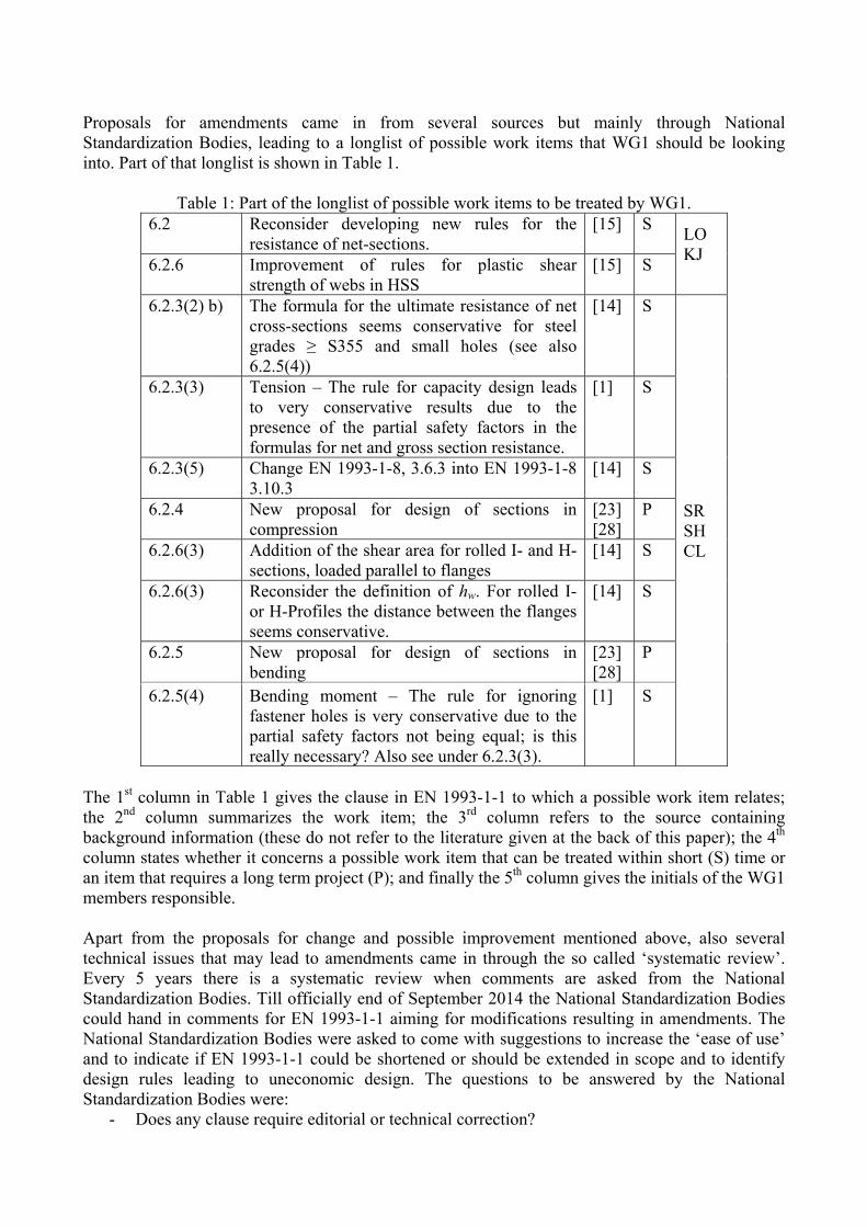
Proposals for amendments came in from several sources but mainly through National Standardization Bodies, leading to a longlist of possible work items that WG1 should be looking into. Part of that longlist is shown in Table 1.
Table 1: Part of the longlist of possible work items to be treated by WG1. 6.2 Reconsider developing new rules for the
resistance of net-sections. [15] S
LO KJ
6.2.6 Improvement of rules for plastic shear strength of webs in HSS
[15] S
6.2.3(2) b) The formula for the ultimate resistance of net cross-sections seems conservative for steel grades ≥ S355 and small holes (see also 6.2.5(4))
[14] S
SR SH CL
6.2.3(3) Tension – The rule for capacity design leads to very conservative results due to the presence of the partial safety factors in the formulas for net and gross section resistance.
[1] S
6.2.3(5) Change EN 1993-1-8, 3.6.3 into EN 1993-1-8 3.10.3
[14] S
6.2.4 New proposal for design of sections in compression
[23] [28]
P
6.2.6(3) Addition of the shear area for rolled I- and H-sections, loaded parallel to flanges
[14] S
6.2.6(3) Reconsider the definition of hw. For rolled I- or H-Profiles the distance between the flanges seems conservative.
[14] S
6.2.5 New proposal for design of sections in bending
[23] [28]
P
6.2.5(4) Bending moment – The rule for ignoring fastener holes is very conservative due to the partial safety factors not being equal; is this really necessary? Also see under 6.2.3(3).
[1] S
The 1st column in Table 1 gives the clause in EN 1993-1-1 to which a possible work item relates; the 2nd column summarizes the work item; the 3rd column refers to the source containing background information (these do not refer to the literature given at the back of this paper); the 4th column states whether it concerns a possible work item that can be treated within short (S) time or an item that requires a long term project (P); and finally the 5th column gives the initials of the WG1 members responsible. Apart from the proposals for change and possible improvement mentioned above, also several technical issues that may lead to amendments came in through the so called ‘systematic review’. Every 5 years there is a systematic review when comments are asked from the National Standardization Bodies. Till officially end of September 2014 the National Standardization Bodies could hand in comments for EN 1993-1-1 aiming for modifications resulting in amendments. The National Standardization Bodies were asked to come with suggestions to increase the ‘ease of use’ and to indicate if EN 1993-1-1 could be shortened or should be extended in scope and to identify design rules leading to uneconomic design. The questions to be answered by the National Standardization Bodies were:
- Does any clause require editorial or technical correction?

- Which clause would benefit from improvements in clarity? - Where should the scope of EN 1993-1-1 be extended? - Where could EN 1993-1-1 be shortened? - Are there any clauses leading to uneconomic design? - Are there any clauses leading to excessive design effort?
The answers received from the National Standardization Bodies to these questions have to be dealt with by SC3 and WG1 is doing the preparatory work for that concerning EN 1993-1-1. This work is in progress and should ideally be ready by October 2017. This was the situation until September 2015 when a Project Teams were established under mandate M/515 of the European Union: ‘M/515 Mandate for amending existing Eurocodes and extending the scope of structural Eurocodes’. PT1 is responsible for EN 1993-1-1. A PT consists of (about) 6 members including the convener and is responsible for the technical work and for writing the new draft of the code. The PT reports to CEN/TC250/SC3 and takes into account the approved amendments so far and the results from the systematic review. The work done by the PT needs the approval of CEN/TC250/SC3. On behalf of CEN/TC250/SC3, WG1 will monitor the work done by PT1 but final decisions on the content of the next version of EN 1993-1-1 are up to SC3. PT1 has to complete its work by June 2018 resulting in a draft for the next version of EN 1993-1-1. Then some time is necessary for administrative purposes so that the next version of EN 1993-1-1 is expected to be published 2020 at the earliest. Also time is needed for translations in other languages than English and for further implementation and embedding in national law where appropriate. In the next version of all Eurocodes, also in the next version of EN 1993-1-1, it is the ambition to have less Nationally Determined Parameters (NDP). EN 1993-1-1 has currently 25 NDP’s. The clauses where they apply are listed right before the start of the first chapter of the code. The values of these NDP’s are given in National Annexes (NA). NDP’s exist because the safety of building structures is still a national responsibility so that each country should be able to make its own choice with respect to the safety level through the values of the relevant NDP’s. NDP’s can also relate to climatic and geographical data specific for a country. To minimize the number of NDP’s, one of the future tasks is to compare the NA’s to see which national choices have been made and to try to harmonize these. NA’s may also contain non-contradictory complementary information (NCCI). It is also the ambition to see if this NCCI is relevant or not and can be either omitted or harmonized. Further, NA’s can change the status of an informative annex into normative or not applicable. Informative annexes are avoided in the next version of EN 1993-1-1. CEN/TC250/SC3 took the following decisions with respect to the annexes:
- Currently two methods for beam-column design are present in the code in cl. 6.3.3 of EN 1993-1-1: Method 1 with Annex A and Method 2 with Annex B. Since Annex B has been developed further and now has a wider scope, only Method 2, Annex B is kept in the code. Thus avoiding alternative design rules for the same phenomenon. Then large parts of Annex B can be included in the main text. Method 1 and Annex A will be transferred to a Technical Specification, which still has to be made: “CEN/TS 1993-1-101 Eurocode3 - Design of steel structures - Part 1-101: Alternative interaction method for members in bending and compression”. So, Annex A is removed from the code and Annex B is either partly or completely moved to the main text of EN 1993-1-1.
- Annex AB.1 contains clauses on how to perform the structural analysis in case of taking into account material non-linearities and is moved to the main text: chapter 5 of EN 1993-1-1. It is tried to move Annex AB.2 on load arrangements for continuous floor beams to other parts of Eurocode 3. These two actions make Annex AB superfluous.
- Annex BB.1 on elastic flexural buckling in lattice structures is kept, clarified where necessary and made normative. Annex BB.2 on restraint stiffness is made normative as well. Annex BB.3 on the stable length method for lateral torsional buckling has limited use throughout all countries using the Eurocode and is transferred into a Technical

Specification, which still has to be made: “CEN/TS 1993-1-102 Eurocode 3 - Design of steel structures - Part 1-102: Stable length method for members containing plastic hinges subject to out-of-plane buckling”. Thus, Annex BB is considerably shortened and made normative.
The next version of EN 1993-1-1 should also be easier to use. Therefore it is tried to: - improve clarity with respect to structure and wording; - harmonize and simplify rules: format, structure, denotations; - provide all information that a user needs to apply a design rule; - harmonize with other parts within Eurocode 3, with other Eurocodes and with other codes
where possible; - produce background documents justifying and explaining the design rules; - simplify routes through the code; - limit parallel alternative rules; - revisit application rules to see if they are really necessary; - remove impractical rules; - shorten the content where possible; - leave out informative annexes which are ‘nice to have’ but not really necessary.
It was decided to keep the overall structure of EN 1993 and its parts. One exception is EN 1993-1-12 [3] for high-strength steel, the content of which will be subdivided over the relevant parts of EN 1993. Another exception forms the new code part “EN 1993-1-13, Eurocode 3: Design of steel structures - part 1-13: Steel beams with large web openings”. CEN/TC250/SC3 decided to have this new code part and work on it is underway. Keeping the overall structure of EN 1993 and its parts as much as possible was done because in the meantime practicing structural engineers are used to this structure. Sometimes the ambitions listed above can be contradictory, e.g. to provide all relevant information for the application of a design rule versus shortening the content where possible. An example of this is elastic critical buckling. In the systematic review many countries asked for elastic critical buckling solutions for flexural and lateral torsional buckling to be included in EN 1993-1-1. However, it was decided by CEN/TC250/SC3 not to include extensive information on elastic critical buckling forces, buckling lengths and elastic critical lateral torsional buckling moments, which are necessary when applying the buckling design rules. Inclusion of this information would lead to EN 1993-1-1 being a text book on applied mechanics instead of a code. But it was decided to make a Technical Report. Work is in progress on this Technical Report containing accepted solutions for elastic critical buckling: CEN/TR1993-1-103 “Eurocode3 - Design of steel structures - Part 1-103: Elastic critical buckling of members”. 2. Amendments The (accepted) amendments have been drafted following a specific format containing the following elements: topic, clause of EN 1993-1-1, reason for the amendment, proposed change and background information. The advantage of this is, that not only the amendment itself in the form of a changed clause is laid down, but also the reason for the amendment and the background information on which the amendment is based. This will help the code drafting process in the future. Up to now (May 2017), CEN/TC250/SC3 accepted amendments on the following topics:
Scope with respect to material thickness; Shear resistance; Semi-compact cross-section design; Member buckling design rules; High-strength steel;
Buckling curves for angles; Buckling curves for heavy sections; Buckling curves for rolled I- and H- sections in S460; Parameter α for cross-section classification; Torsion and its interaction with other internal forces.
Further, amendments are prepared on the following topics: Local load introduction without stiffeners; Tubular members under bending and axial compression; Elliptical hollow sections; Initial bow imperfections of table 5.1 of EN 1993-1-1.
The amendments are summarized below. The formulations of the amendments below may be subject to editorial changes. 2.1 Scope with respect to material thickness See [1]. Relevant references are [4 to 6]. 2.2 Shear resistance See [1]. Relevant reference is [7]. 2.3 Semi-compact cross-section design See [1]. Relevant references [8 to 13]. 2.4 Member buckling design rules See [1]. Relevant references are [8, 14 to 21]. 2.5 High-strength steel It was decided by subcommittee CEN/TC250/SC3 that EN 1993-1-12 containing supplementary rules for high-strength steel shall not be a separate document and that its content shall be included in the relevant parts of EN 1993. The amendments of [22 to 24] concern the consequences of this decision for EN 1993-1-1. In clause 1.1.1(6) of EN 1993-1-1, being part of the scope of Eurocode 3, part EN 1993-1-12 is removed. In clause 1.2.2 of EN 1993-1-1 on weldable structural steel reference standards, two standards are added:
- EN 10149-1, ‘Hot-rolled flat products made of high yield strength steels for cold forming – Part 1: General delivery conditions;
- EN 10149-2, ‘Hot-rolled flat products made of high yield strength steels for cold forming – Part 2: Delivery conditions for thermomechanically rolled steels.
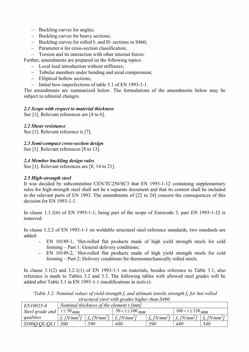
In clause 3.1(2) and 3.2.1(1) of EN 1993-1-1 on materials, besides reference to Table 3.1, also reference is made to Tables 3.2 and 3.3. The following tables with allowed steel grades will be added after Table 3.1 in EN 1993-1-1 (modifications in italics):
‘Table 3.2: Nominal values of yield strength fy and ultimate tensile strength fu for hot rolled structural steel with grades higher than S460.
EN10025-6 Steel grade and qualities
Nominal thickness of the element t [mm] 50t mm 10050 t mm 150100 t mm
fy [N/mm2] fu [N/mm2] fy [N/mm2] fu [N/mm2] fy [N/mm2] fu [N/mm2] S500Q/QL/QL1 500 590 480 590 440 540

S550Q/QL/QL1 550 640 530 640 490 590 S620Q/QL/QL1 620 700 580 700 560 650 S690Q/QL/QL1 690 770 650 760 630 710
Table 3.3: Nominal values of yield strength fy and ultimate tensile strength fu for hot rolled flat products.
EN 10149-2a) 8t mm 168 t mm
fy [N/mm2] fu [N/mm2] fy [N/mm2] fu [N/mm2] S500MC 500 550 500 550 S550MC 550 600 550 600 S600MC 600 650 600 650 S650MC 650 700 630 700 S700MC 700 650 680 750 a) Verification of the impact energy in accordance with EN10149-1 Clause 11, Option 5 should be specified
NOTE The National Annex may specify additional rules for steels according to Tables 3.2 and 3.3 EDITORIAL NOTE by WG EN 1993-1-12: Tables 3.2 and 3.3 need to be checked for published amendments and corrigenda.’ Clause 3.2.2 on ductility requirements is modified as follows (modifications in italics): ‘3.2.2 Ductility requirements (1) For steels a minimum ductility is required that should be expressed in terms of limits for:
- the ratio fu/fy of the specified minimum ultimate tensile strength fu to the specified minimum yield strength fy;
- the elongation at failure on a gauge length of 5.65 oA (where oA is the original cross-
sectional area); - the ultimate strain u , where u corresponds to the ultimate strength fu. NOTE The limiting values of the ratio fu/fy, the elongation at failure and the ultimate strain u may be defined in the National Annex. The following values are recommended: a) For plastic global analysis
- 10,1/ yu ff ;
- elongation at failure not less than 15%; - yu 15 , where y is the yield strain ( Ef yy / ).
b) For elastic global analysis - 05.1/ yu ff ;
- elongation at failure not less than 12%.
(2) Steel conforming to one of the steel grades listed in Table 3.1 should be accepted as satisfying these requirements for plastic global analysis. Steels conforming to one of the steel grades listed in Tables 3.2 and 3.3 should be accepted as satisfying the requirements for elastic global analysis.’ The clauses 5.4.1(3) and 5.4.1(4)B of EN 1993-1-1 are modified as follows (modifications in italics): ‘(3) Plastic global analysis may be used for structures with members made of steels according to Table 3.1 and where the structure has sufficient rotation capacity at the actual locations of the
plastic hinges, whether this is in the members or in the joints. Where a plastic hinge occurs in a member, the member cross sections should be double symmetric or single symmetric with a plane of symmetry in the same plane as the rotation of the plastic hinge and it should satisfy the requirements specified in 5.6. Where a plastic hinge occurs in a joint the joint should either have sufficient strength to ensure the hinge remains in the member or should be able to sustain the plastic resistance for a sufficient rotation, see EN 1993-1-8. (4)B As a simplified method for a limited plastic redistribution of moments in continuous beams where following an elastic analysis some peak moments exceed the plastic bending resistance of 15 % maximum, the parts in excess of these peak moments may be redistributed in any member, provided, that:
a) the internal forces and moments in the frame remain in equilibrium with the applied loads, and
b) all the members in which the moments are reduced are of steels according to Table 3.1 and have Class 1 or Class 2 cross-sections (see 5.5), and
c) lateral torsional buckling of the members is prevented.’ Clause 5.4.3(1) of EN 1993-1-1 is supplemented as follows (modifications in italics): ‘(l) Plastic global analysis allows for the effects of material non-linearity in calculating the action effects of a structural system. The behavior should be modelled by one of the following methods: a) by elastic-plastic analysis with plastified sections and/or joints as plastic hinges, b) by non-linear plastic analysis considering the partial plastification of members in plastic zones, c) by rigid plastic analysis neglecting the elastic behavior between hinges. NOTE 1 In case the method according to 5.4.3(1)b) is followed, also steels according to
Tables 3.2 and 3.3 may be used because the real stress-strain curves including strain limitations are then considered. If steels according to Tables 3.2 and 3.3 are used, geometric imperfections on the level of cross-sections should be included in the analysis because local bending of flanges and webs can become important in the plastic domain.
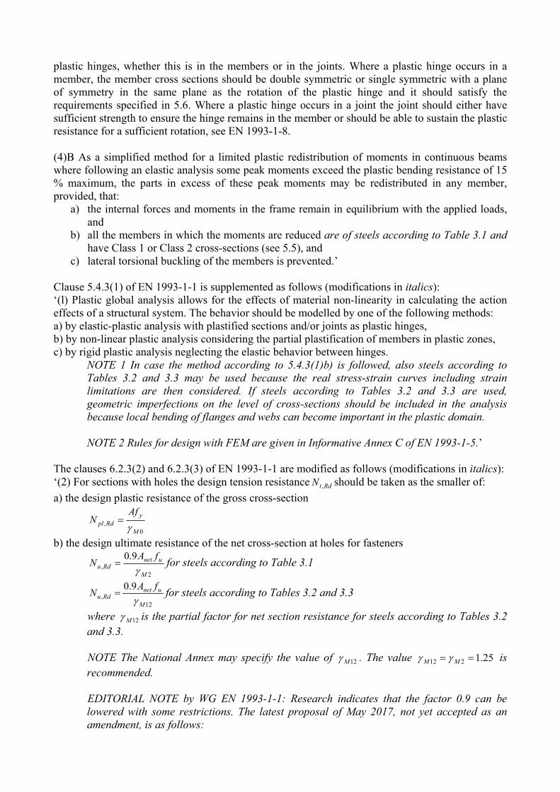
NOTE 2 Rules for design with FEM are given in Informative Annex C of EN 1993-1-5.’ The clauses 6.2.3(2) and 6.2.3(3) of EN 1993-1-1 are modified as follows (modifications in italics): ‘(2) For sections with holes the design tension resistance RdtN , should be taken as the smaller of:
a) the design plastic resistance of the gross cross-section
0
,M
yRdpl
AfN
b) the design ultimate resistance of the net cross-section at holes for fasteners
2
,
9.0
M
unetRdu
fAN
for steels according to Table 3.1
12,
9.0
M
unetRdu
fAN
for steels according to Tables 3.2 and 3.3
where 12M is the partial factor for net section resistance for steels according to Tables 3.2 and 3.3. NOTE The National Annex may specify the value of 12M . The value 25.1212 MM is recommended. EDITORIAL NOTE by WG EN 1993-1-1: Research indicates that the factor 0.9 can be lowered with some restrictions. The latest proposal of May 2017, not yet accepted as an amendment, is as follows:

Replace the factor 0.9 by a factor k where: - k = 1.0 for sections with smooth holes (i.e. holes without notches), for example holes fabricated by drilling or water jet cutting; - k = 0.9 for sections with rough holes (i.e. holes with notches), for example holes fabricated by punching or flame cutting; - k = 0.9 for structures subjected to fatigue.
(3) Where capacity design is requested, see EN 1998, the design plastic resistance RdplN , (as given in
6.2.3(2) a)) should be less than the design ultimate resistance of the net section at fasteners holes RduN , (as in 6.2.3(2) b)). Steels according to Tables 3.2 and 3.3 should not be used for
applications where capacity design is required’ Finally, in Table 6.2 of EN 1993-1-1 for the selection of buckling curves, the material S450 should be added to the column where the materials S235, S275, S355 and S420 are mentioned while S460 up to and including S700 should be written in the column where S460 is mentioned. 2.6 Buckling curves for angles See [1]. Relevant references are [25]. 2.7 Buckling curves for heavy sections This amendment [29] fills a gap in the current buckling curve selection Table 6.2 of EN 1993-1-1. For rolled sections with height to width ratio h/b > 1.2 buckling curves are not specified for flange thicknesses tf > 100mm. However, these sections are available nowadays. The present gap in Table 6.2 of EN 1993-1-1 hampers the use of these innovative European products. Table 2 shows the part of the current Table 6.2 of EN 1993-1-1 for rolled I- and H-sections. Based on research reported in [30 to 32] Table 6.2 of EN 1993-1-1 is now supplemented for heavy sections with height to width ration h/b > 1.2 and flange thicknesses tf > 100mm, see Table 3 (modifications in italics). Note that the steel grades up to and including S700 have been added to the table.
Table 2: Part of Table 6.2 of EN 1993-1-1 for the selection of a buckling curve for rolled sections.
Cross-section Limits Buckling
about axis
Buckling curve S235 S275 S355 S420
S460
Rol
led
sect
ions
h/b
> 1
.2 tf ≤ 40 mm
40 < tf ≤ 100 mm
y-y z-z
y-y z-z
a b b c
a0 a0 a a
h/b ≤
1.2 tf ≤ 100 mm
tf > 100 mm
y-y z-z
y-y z-z
b c d d
a a c c
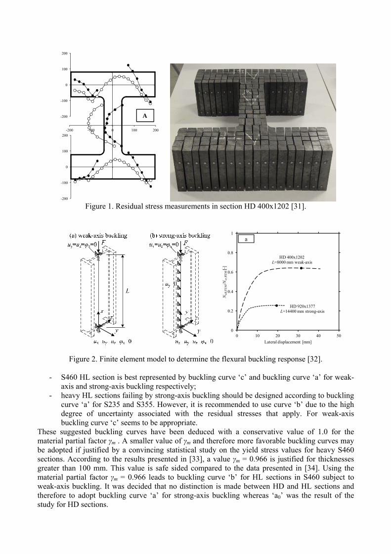
In order to extend the application range of Table 6.2 of EN 1993-1-1, a research project was carried
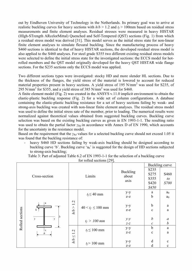
out by Eindhoven University of Technology in the Netherlands. Its primary goal was to arrive at realistic buckling curves for heavy sections with h/b > 1.2 and tf > 100mm based on residual stress measurements and finite element analyses. Residual stresses were measured in heavy HISTAR (HIgh-STrength ARcelorMittal) Quenched and Self-Tempered (QST) sections (Fig. 1) from which a residual stress model was derived [31]. This model serves as the initial stress state for non-linear finite element analyses to simulate flexural buckling. Since the manufacturing process of heavy S460 sections is identical to that of heavy HISTAR sections, the developed residual stress model is also applied to the S460 analyses. For steel grade S355 two different existing residual stress models were selected to define the initial stress state for the investigated sections: the ECCS model for hot-rolled members and the QST model originally developed for the heavy QST HISTAR wide flange sections. For the S235 sections only the ECCS model was applied. Two different sections types were investigated: stocky HD and more slender HL sections. Due to the thickness of the flanges, the yield stress of the material is lowered to account for reduced material properties present in heavy sections. A yield stress of 195 N/mm2 was used for S235, of 295 N/mm2 for S355, and a yield stress of 385 N/mm2 was used for S460. A finite element model (Fig. 2) was created in the ANSYS v.11.0 implicit environment to obtain the elastic-plastic buckling response (Fig. 2) for a wide set of column configurations. A database containing the elastic-plastic buckling resistance for a set of heavy sections failing by weak- and strong-axis buckling was created with non-linear finite element analyses. The residual stress model was used to define the initial stress sate of the member, prior to loading. The numerical results were normalized against theoretical values obtained from suggested buckling curves. Buckling curve selection was based on the existing buckling curves as given in EN 1993-1-1. The resulting ratio was used to obtain the partial factor γRd in accordance with Annex D of EN 1990, which accounts for the uncertainty in the resistance model. Based on the requirement that the γRd values for a selected buckling curve should not exceed 1.05 it was found that the buckling resistance of:
- heavy S460 HD sections failing by weak-axis buckling should be designed according to buckling curve ‘b’. Buckling curve ‘a0’ is suggested for the design of HD sections subjected to strong-axis buckling;
Table 3: Part of adjusted Table 6.2 of EN 1993-1-1 for the selection of a buckling curve for rolled sections [29].
Cross-section Limits Buckling
about axis
Buckling curve S235 S275 S355 S420 S450
S460 to
S700
Rol
led
sect
ions
h/b
> 1
.2
tf ≤ 40 mm
40 < tf ≤ 100 mm
tf > 100 mm
y-y z-z
y-y z-z
y-y z-z
a b b c b c
a0 a0 a a a b
h/b ≤
1.2 tf ≤ 100 mm
tf > 100 mm
y-y z-z
y-y z-z
b c d d
a a c c
-200
-100
0
100
200-200 -100 0 100 200
-200
-100
0
100
200
A
Figure 1. Residual stress measurements in section HD 400x1202 [31].
0
0.2
0.4
0.6
0.8
1
0 10 20 30 40 50
Nul
t;FE
M/N
cr;F
EM
[-]
Lateral displacement [mm]
HD 400x1202 L=8000 mm weak-axis
HD 920x1377L=14400 mm strong-axis
a
Figure 2. Finite element model to determine the flexural buckling response [32].
- S460 HL section is best represented by buckling curve ‘c’ and buckling curve ‘a’ for weak-axis and strong-axis buckling respectively;
- heavy HL sections failing by strong-axis buckling should be designed according to buckling curve ‘a’ for S235 and S355. However, it is recommended to use curve ‘b’ due to the high degree of uncertainty associated with the residual stresses that apply. For weak-axis buckling curve ‘c’ seems to be appropriate.
These suggested buckling curves have been deduced with a conservative value of 1.0 for the material partial factor γm . A smaller value of γm and therefore more favorable buckling curves may be adopted if justified by a convincing statistical study on the yield stress values for heavy S460 sections. According to the results presented in [33], a value γm = 0.966 is justified for thicknesses greater than 100 mm. This value is safe sided compared to the data presented in [34]. Using the material partial factor γm = 0.966 leads to buckling curve ‘b’ for HL sections in S460 subject to weak-axis buckling. It was decided that no distinction is made between HD and HL sections and therefore to adopt buckling curve ‘a’ for strong-axis buckling whereas ‘a0’ was the result of the study for HD sections.
2.8 Buckling curves for rolled I- and H- sections in S460 See [1]. Relevant references are [35 to 37]. 2.9 Parameter α for cross-section classification This amendment [38] facilitates the determination of the parameter α in Table 5.2 of EN 1993-1-1 for the cross-section classification. This parameter is used to determine the cross-section class of internal parts subjected to bending and compression. A note is added to Table 5.2 (sheet 1/3) of EN 1993-1-1 explaining how to determine the parameter α, as follows (modifications in italics): ‘Note: for I or H sections with equal flanges, under axial force and bending moment about the main axis parallel to the flanges, the parameter α that defines the position of the plastic neutral axis may be calculated as follows: If NEd ≥ c tw fy then α = 1,0; If NEd ≤ -c tw fy then α = 0; In other cases: α = 0,5 [1 + NEd / (c tw fy)] Where NEd is the design axial force taken as positive for compression and negative for tension.’ 2.10Torsion and its interaction with other internal forces Amendment [39] concerns the interaction of torsion with other internal forces. There is a lack in EN 1993-1-1 concerning the consideration of torsion and its interaction with other internal forces. A simple formulation to take bending-warping torsion interaction and bending-shear-torsion interaction into account for doubly symmetrical I-sections with class 1 and class 2 cross-sections is introduced. This is based on the formulation already provided in EN1993-1-1 for the consideration of shear-torsion interaction in clause 6.2.7(9) of EN 1993-1-1. To clause 6.2.7 (6) of EN 1993-1-1 the following is added (modifications in italics): ‘The reduced design plastic resistance moment allowing for the bimoment Bed may be obtained for I-cross sections with equal flanges and bending about the major axis as follows:
RdplMy
EdwRdBc M
fM ,
0
max,,,, 25,1
1
where Mpl,Rd is given in 6.2.5 and σw,Ed,max is the maximum direct stress σw,Ed due to the bimoment BEd.’ Clause 6.2.8(5) is changed as follows (modifications in italics): ‘For doubly symmetrical I-sections with class 1 and class 2 cross-sections, when torsion is present, the reduced design plastic resistance moment should be taken as the design resistance of the cross-section calculated using a reduced yield strength as follows:
Rdc
RdBcy M
Mf
,
,,1 for the shear area
Rdc
RdBcy M
Mf
,
,, for the rest of the cross-section
where Mc,B,Rd is given in 6.2.7 (6) and 2
,,
12
RdTpl
Ed
V
V , see 6.2.7, but should be taken
as 0 for VEd ≤ 0,5 Vpl,T,Rd. When warping torsion is not present, then Mc,B,Rd = Mc,Rd.

Alternatively, the reduced design plastic resistance moment allowing for the shear force and the bimoment may be obtained for doubly symmetrical I-sections with class 1 and class 2 cross-sections, bending about the major axis y-y, as follows:
Rdcy
RdBcy
M
w
wypl
RdVBy M
Mf
t
AW
M,,
,,,
0
2
,
,,,
4
but My,B,V,Rd ≤ My,c,B,Rd
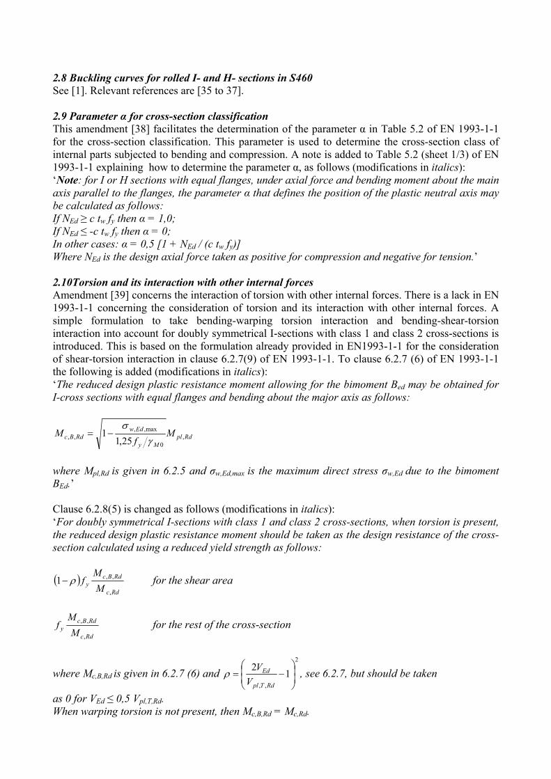
where My,c,Rd is obtained from 6.2.5 (2) and My,c,B,Rd is obtained from 6.2.7 (6), and Aw = hwtw. When warping torsion is not present, then My,c,B,Rd = My,c,Rd.’ Figure 3 shows the effect of several clauses of EN 1993-1-1 and the amendments mentioned on the bending-shear-torsion interaction diagram.
Figure 3. Development of bending-shear-torsion interaction diagram [39]
2.11 Local load introduction without stiffeners This amendment [40] treats a new topic in EN 1993-1-1 namely local load introduction without
Repair of inconsistency for VEd
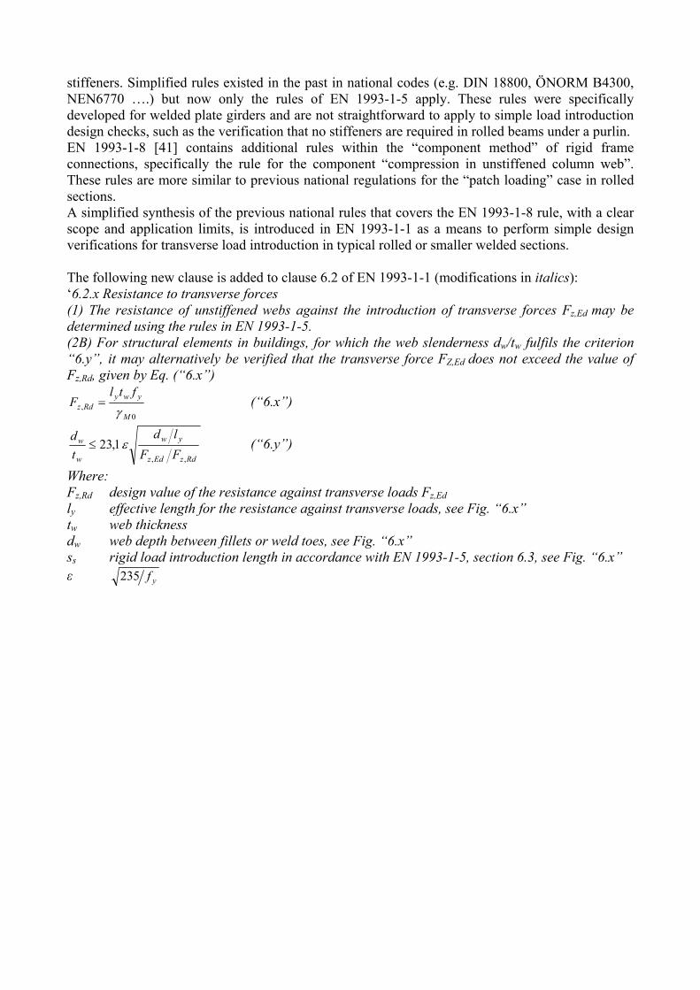
stiffeners. Simplified rules existed in the past in national codes (e.g. DIN 18800, ÖNORM B4300, NEN6770 ….) but now only the rules of EN 1993-1-5 apply. These rules were specifically developed for welded plate girders and are not straightforward to apply to simple load introduction design checks, such as the verification that no stiffeners are required in rolled beams under a purlin. EN 1993-1-8 [41] contains additional rules within the “component method” of rigid frame connections, specifically the rule for the component “compression in unstiffened column web”. These rules are more similar to previous national regulations for the “patch loading” case in rolled sections. A simplified synthesis of the previous national rules that covers the EN 1993-1-8 rule, with a clear scope and application limits, is introduced in EN 1993-1-1 as a means to perform simple design verifications for transverse load introduction in typical rolled or smaller welded sections. The following new clause is added to clause 6.2 of EN 1993-1-1 (modifications in italics): ‘6.2.x Resistance to transverse forces (1) The resistance of unstiffened webs against the introduction of transverse forces Fz,Ed may be determined using the rules in EN 1993-1-5. (2B) For structural elements in buildings, for which the web slenderness dw/tw fulfils the criterion “6.y”, it may alternatively be verified that the transverse force FZ,Ed does not exceed the value of Fz,Rd, given by Eq. (“6.x”)
0,
M
ywyRdz
ftlF
(“6.x”)
RdzEdz
yw
w
w
FF
ld
t
d
,,
1,23 (“6.y”)
Where: Fz,Rd design value of the resistance against transverse loads Fz,Ed ly effective length for the resistance against transverse loads, see Fig. “6.x” tw web thickness dw web depth between fillets or weld toes, see Fig. “6.x” ss rigid load introduction length in accordance with EN 1993-1-5, section 6.3, see Fig. “6.x” ε yf235

Fig. 6.x: Definition of the lengths ly, dw and ss’
2.12 Tubular members under bending and axial compression In [42] amendment proposals are made and extensively motivated for tubular members under bending and axial compression. Here only the results are summarized. For the cross-section classification of tubular members, a distinction is made in cross-sections in compression and in bending. Table 5.2 (sheet 3 of 3) of EN 1993-1-1 is modified accordingly [42] (modifications in italics):
‘Table 5.2 (sheet 3 of 3)… Class Section in compression Section in bending 1 2
1 50 cat
d 2
1 50 bat
d
2 22 70 ca
t
d 2
2 70 bat
d
3 23 70 ca
t
d 2
3 140 bat
d
’ For class 1 and 2 cross-sections, the moment normal force interaction as proposed is [42]:
RdplRdpl
Ed
p
Rdpl
Ed
Rdpl
EdRdplN M
b
N
N
N
N
N
NM ,
2
,,2
,,, 1
Where:
d
tp 5,1481,3
048.0274,0267,3 2 ppb For class 3 cross-sections, the moment normal force interaction as proposed is [42]:

yRdpl
RdplNRdepN ftd
aa
aas
M
MM 2
68,0
23
2
,
,,,, 11
Where:
Rdpl
RdplN
Rdpl
Ed
M
M
N
N
s
,
,,
,
1
785,0
t
da
kakaa bc 1222 kakaa bc 1333
plEd
plEd
NM
MNk arctan
2
2.13 Elliptical hollow sections Elliptical hollow sections (EHS) are available and EN 1993-1-1 anticipates on this innovation by inclusion of design rules for them [43]. The design rules concern various clauses in EN 1993-1-1. In Table 5.2 (sheet 3 of 3) Fig. 4 is added with the following text and formulas (modifications in italics): ‘Equivalent diameters de: For CHS de=d; for EHS de depends on the nature of loading.
For EHS in compression:
13,211 6,0
b
hhthde or conservatively
b
hde
2
.
For EHS in major (y-y) axis bending: if 36,1b
hthen
h
bde
2
, if 36,1b
h then
b
hde
2
4,0 .
For EHS in minor (z-z) axis bending or compression and minor axis bending: b
hde
2
.
For EHS in compression and major (y-y) axis bending, de may be determined by linear interpolation between the equivalent diameter for compression and that for bending based on the factor α for Class 1 and 2 cross-sections and ψ for Class 3 and 4 cross-sections.’
Figure 4. Elliptical hollow section (EHS) definitions [43]
Clause 6.2.2.5 of EN 1993-1-1 is modified and extended as follows (modifications in italics): ‘(5)a) For class 4 circular or elliptical hollow sections in compression, the effective cross-sectional are Aeff may be determined as:
5.023590
yeeff ftd
AA for 2240tde
b) For class 4 circular or elliptical hollow sections in bending, the effective section modulus Weff may be determined as:
25.0235140
yeeleff ftd
WW for 2240tde
(6) For circular or elliptical hollow sections exceeding the specified limits see EN 1993-1-6.’ Clause 6.2.6(3) of EN 1993-1-1is extended defining the shear area for EHS (modifications in italics): ‘h) rolled elliptical hollow sections of uniform thickness: load parallel to the depth 2(h-t)/t load parallel to width 2(b-t)/t’ Clause 6.2.6(6) of EN 1993-1-1 is extended adding design rules for shear buckling as follows (modifications in italics): ‘(6)a) In addition… … b) For circular or elliptical hollow sections of uniform thickness, shear buckling resistance should be according to section 8 of EN 1993-1-6, when:
2100t
td for CHS
2100t
th for EHS loaded parallel to the height
2100t
tb for EHS loaded parallel to the width’
Clause 6.2.8 of EN 1993-1-1 for combined bending and shear resistance is extended as follows (modifications in italics): ‘(3)a) Otherwise… … b) For circular and elliptical hollow sections of uniform thickness, the reduced moment resistance should be taken as the design resistance of the cross-section, calculated using a reduced yield strength from Equation (6.29) for the full cross-section area.’ Clause 6.2.9.1 of EN 1993-1-1 is extended to include a design rule combined bending and axial force for EHS (modifications in italics): ‘(7) For elliptical hollow sections of uniform thickness, the following criterion may be used:
0,12
7,1
,,
,
2
,,
,
5,3
,
75,1
,
Rdzpl
Rdz
Rdypl
Edy
Rdc
Ed
Rdc
Ed
M
M
M
M
N
N
N
N’
Clause 6.2.10 of EN 1993-1-1 for combined bending, and axial force is extended as follows (modifications in italics): ‘(3)a) Where… … b) For circular and elliptical hollow sections of uniform thickness, where VEd exceeds 50% of Vpl,Rd
the design resistance of the cross-section to combinations of moment and axial force should be calculated using a reduced yield strength from Equation (6.45) for the full cross-section area.’
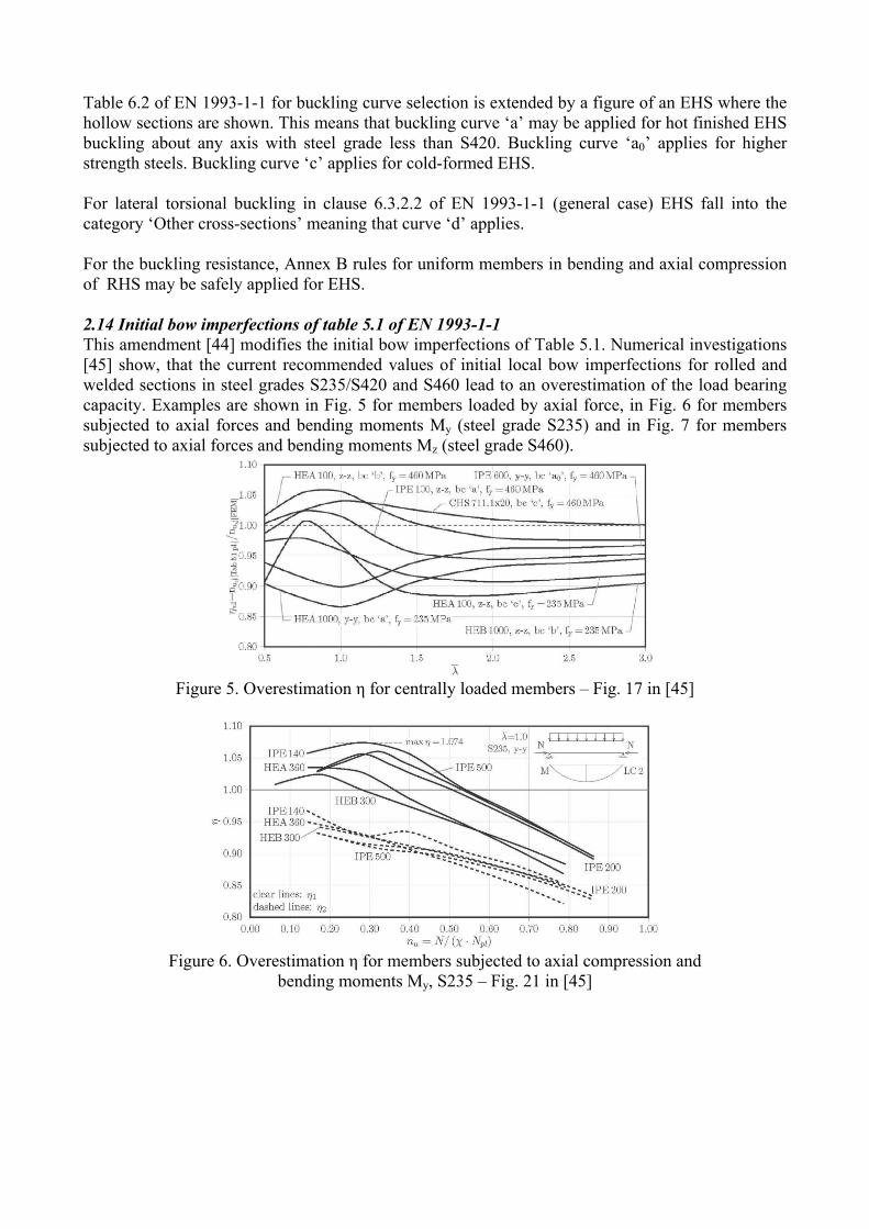
Table 6.2 of EN 1993-1-1 for buckling curve selection is extended by a figure of an EHS where the hollow sections are shown. This means that buckling curve ‘a’ may be applied for hot finished EHS buckling about any axis with steel grade less than S420. Buckling curve ‘a0’ applies for higher strength steels. Buckling curve ‘c’ applies for cold-formed EHS. For lateral torsional buckling in clause 6.3.2.2 of EN 1993-1-1 (general case) EHS fall into the category ‘Other cross-sections’ meaning that curve ‘d’ applies. For the buckling resistance, Annex B rules for uniform members in bending and axial compression of RHS may be safely applied for EHS. 2.14 Initial bow imperfections of table 5.1 of EN 1993-1-1 This amendment [44] modifies the initial bow imperfections of Table 5.1. Numerical investigations [45] show, that the current recommended values of initial local bow imperfections for rolled and welded sections in steel grades S235/S420 and S460 lead to an overestimation of the load bearing capacity. Examples are shown in Fig. 5 for members loaded by axial force, in Fig. 6 for members subjected to axial forces and bending moments My (steel grade S235) and in Fig. 7 for members subjected to axial forces and bending moments Mz (steel grade S460).
Figure 5. Overestimation η for centrally loaded members – Fig. 17 in [45]
Figure 6. Overestimation η for members subjected to axial compression and
bending moments My, S235 – Fig. 21 in [45]
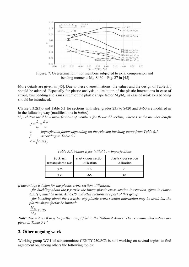
Figure. 7. Overestimation η for members subjected to axial compression and
bending moments Mz, S460 – Fig. 27 in [45] More details are given in [45]. Due to these overestimations, the values and the design of Table 5.1 should be adapted. Especially for plastic analysis, a limitation of the plastic interactions in case of strong axis bending and a maximum of the plastic shape factor Mpl/Mel in case of weak axis bending should be introduced. Clause 5.3.2(3)b and Table 5.1 for sections with steel grades 235 to S420 and S460 are modified in in the following way (modifications in italics): ‘b) relative local bow imperfections of members for flexural buckling, where L is the member length
0e
Lj
α imperfection factor depending on the relevant buckling curve from Table 6.1 β according to Table 5.1 yf235
Table 5.1. Values β for initial bow imperfections
if advantage is taken for the plastic cross section utilization:
- for buckling about the y-y-axis: the linear plastic cross-section interaction, given in clause 6.2.1(7) must be used. All CHS and RHS sections are part of this group - for buckling about the z-z-axis: any plastic cross section interaction may be used, but the plastic shape factor be limited:
25,1el
pl
M
M
Note: The values β may be further simplified in the National Annex. The recommended values are given in Table 5.1.’ 3. Other ongoing work Working group WG1 of subcommittee CEN/TC250/SC3 is still working on several topics to find agreement on, among others the following topics:

- Moment shear interaction. - Use of the elastic critical buckling mode of the structure as global and local imperfections.
This concerns clause 5.3.2(11) of EN 1993-1-1 where clarifications are necessary. - Buckling design rules for equal legged angles. - Simplified assessment methods for lateral torsional buckling of beams with restraints.
PT1 is working on the next version of EN 1993-1-1 and the 2nd draft is currently (August 2017) available for commenting on [46]. Many of the amendments treated in section 2 have been included in this 2nd draft, but not all of them yet. Now that just one method for verifying the stability of beam-columns is kept in the code, the content of Annex B has been moved to the main text of [46]. The former Annex C on the selection of the execution class has been renamed in Annex A in [46]. The new Annex B treats the design of semi-compact sections. In the 2nd draft of the next version of EN 1993-1-1 [46], clause 5.2 on structural analysis has been modified substantially and in such a way that better reference is given to the design rules to be used in connection to the method of structural analysis applied. For this reason a new Figure 5.3 has been added containing a flow-chart addressing the structural analysis methods available (Fig. 8). The final next version of EN 1993-1-1 should be available in June 2018. Then the technical content is available. Editorial work can be done afterwards and time is necessary for administrative purposes so that the next version of EN 1993-1-1 is expected to be published in 2020 at the earliest. Also time is needed for translations in other languages than English and for further implementation. 4. Conclusions Using EN 1993-1-1 in the past decade led to many proposals for change and possible improvement. Working Group 1 (WG1) of subcommittee CEN/TC250/SC3 worked on these proposals. Some of these proposals turned into accepted amendments. These amendments have been handed over to Project Team 1 (PT1) for EN 1993-1-1, that is responsible for the next version of EN 1993-1-1, due in a few years, in 2020 at the earliest. Also the recently carried out systematic review resulted in work items that can lead to amendments. Both WG1 and PT1 work with as starting point improvement of the ease of use of EN 1993-1-1. Currently, August 2017, the 2nd draft of the next version of EN 1993-1-1 is available for commenting on. In this 2nd draft many of the amendments mentioned in the paper have been included, but not all of them yet. In the paper an overview is given of the amendments so far, concerning: scope with respect to material thickness, shear resistance, semi-compact cross-section design, member buckling design rules, high-strength steel, buckling curves for angles, buckling curves for heavy sections and finally buckling curves for rolled I- and H- sections in S460, parameter α for cross-section classification, torsion and its interaction with other internal forces, local load introduction without stiffeners, tubular members under bending and axial compression, elliptical hollow sections and, initial bow imperfections of table 5.1 of EN 1993-1-1. 5. Acknowledgement The author wishes to thank the members of Working Group 1 of the Eurocode 3 subcommittee
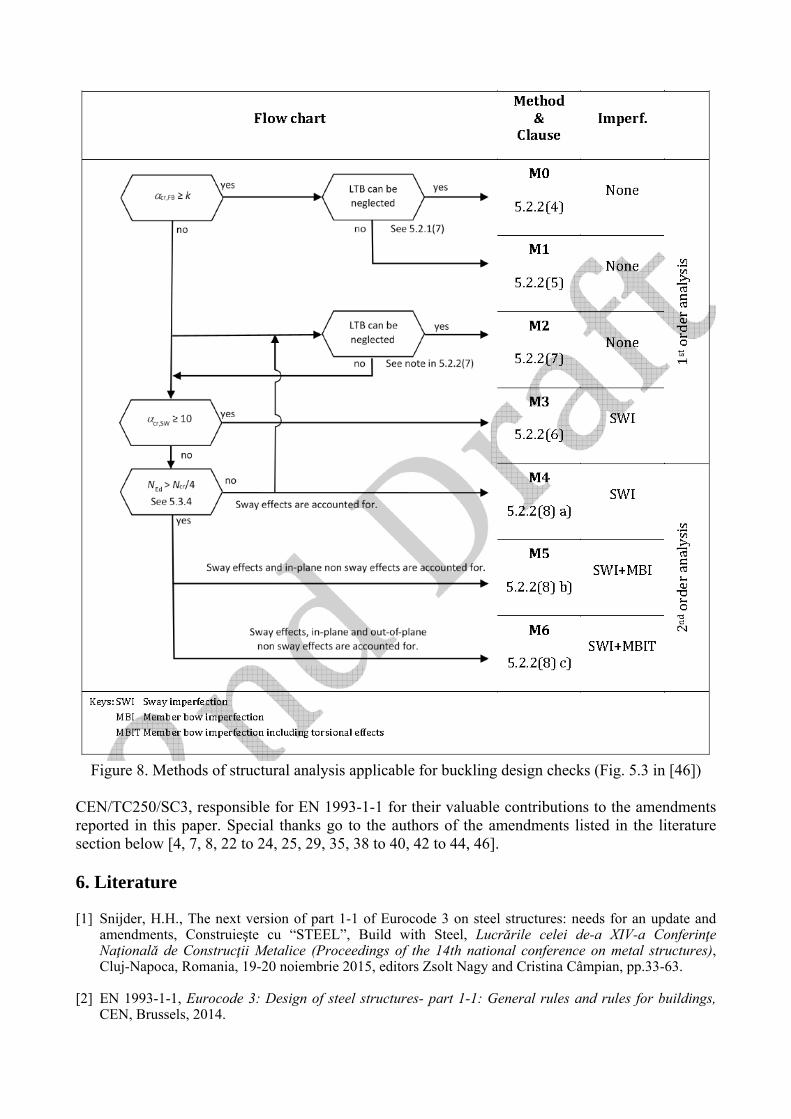
Figure 8. Methods of structural analysis applicable for buckling design checks (Fig. 5.3 in [46])
CEN/TC250/SC3, responsible for EN 1993-1-1 for their valuable contributions to the amendments reported in this paper. Special thanks go to the authors of the amendments listed in the literature section below [4, 7, 8, 22 to 24, 25, 29, 35, 38 to 40, 42 to 44, 46]. 6. Literature [1] Snijder, H.H., The next version of part 1-1 of Eurocode 3 on steel structures: needs for an update and
amendments, Construieşte cu “STEEL”, Build with Steel, Lucrările celei de-a XIV-a Conferinţe Naţională de Construcţii Metalice (Proceedings of the 14th national conference on metal structures), Cluj-Napoca, Romania, 19-20 noiembrie 2015, editors Zsolt Nagy and Cristina Câmpian, pp.33-63.
[2] EN 1993-1-1, Eurocode 3: Design of steel structures- part 1-1: General rules and rules for buildings,
CEN, Brussels, 2014.
[3] EN 1993-1-12, Eurocode 3: Design of steel structures- part 1-12: Additional rules and rules for the
extension of EN 1993 up to steel grades S700, Brussels, 2011. [4] Kouhi J, Larsen PK, Ongelin P, Amendment scope with respect to material thickness, Doc. CEN-TC250-
SC3_N1894, 2013. [5] EN 10210, Hot finished structural hollow sections of non-alloy and fine grain steels. [6] EN 10219, Cold formed welded structural hollow sections of non-alloy and fine grain steels. [7] Stroetmann R, Franz C, Amendment shear, Doc. CEN-TC250-SC3_N1895, 2013._ [8] Taras A, Greiner R, Unterweger H, Proposal for amended rules for member buckling and semi-compact
cross-section design, Doc. CEN-TC250-SC3_N1898, 2013. [9] Greiner R, Kettler M, Lechner A, Jaspart JP, Boissonade N, Bortolotti E, Weynand K, Ziller C, Örder R,
SEMI-COMP: Plastic Member Capacity of Semi- Compact Steel Sections – a more Economic Design, RFSR-CT-2004-00044, Final Report, Research Programme of the Research Fund for Coal and Steel – RTD, 2008.
[10] Greiner R, Kettler M, Lechner A, Jaspart JP, Weynand K, Ziller C, Örder R, SEMI-COMP+:
Valorisation Action of Plastic Member Capacity of Semi-Compact Steel Sections – a more Economic Design, RFS2-CT-2010-00023, Background Documentation, Research Programme of the Research Fund for Coal and Steel – RTD, 2011.
[11] Greiner R, Kettler M, Lechner A, Design proposal for the transition of cross-section and member
resistances from class 2 to class 4, Doc. TC8-2011-06-007, TC8 Meeting, Lisbon, June 2011. [12] Lechner A, Kettler M, Greiner R, Unterweger H, Verbesserte Bemessungsregeln für Stäbe mit Klasse 3
Querschnitt, Stahlbau, Vol. 81, No. 4, pp. 265-281, 2012. [13] Greiner R, Jaspart JP, Weynand K, Lechner A, Kettler M, Simoes da Silva L, Design Guidelines for
Cross-Section and Member Design According to Eurocode 3 with Particular Focus on Semi-Compact Sections, Graz Univ. of Technology, 2011.
[14] Snijder HH, Hoenderkamp JCD, Buckling curves for lateral torsional buckling of unrestrained beams,
Hommages à René Maquoi Birthday Anniversary, Editors Vincent de Ville de Goyet, Jean-Pierre Jaspart and Jacques Rondal, Université de Liège, Belgium, pp. 239-248, 2007.
[15] Rebelo C, Lopes N, Simoes da Silva L, Nethercot D, Vila Real PMM, Statistical Evaluation of the
Lateral-Torsional Buckling Resistance of Steel I-beams, Part 1: Variability of the Eurocode 3 resistance model, Journal of Constructional Steel Research, Vol. 64, No. 4, pp. 818-831, 2008.
[16] Snijder HH, Hoenderkamp JCD, Bakker MCM, Steenbergen HMGM, Bruins RHJ, LTB of steel beams
with restraints between the supports, Eurosteel 2008, 5th European Conference on Steel and Composite Structures, research-practice-new materials, Graz, Austria, Proceedings edited by Robert Ofner, Darko Beg, Josef Fink, Richard Greiner, Harald Unterweger, Published by ECCS, Brussels, Belgium, pp. 1557-1562, 2008.
[17] Taras A, Contribution to the Development of Consistent Stability Design Rules for Steel Members, PhD
thesis, Graz University of Technology, 2010. [18] Greiner R, Taras A, Consistent and Code-Conform Derivation of Buckling Rules for Steel Members,
ECCS TC8 Doc. 2010-06-011, TC8 Oslo meeting, 2010. [19] Greiner R, Taras A, Proposal for Harmonized Buckling Curves for Flexural, TF- and LT-Buckling of
Uniform Members, ECCS TC8 Doc. 2011-06-006, TC8 Lisbon meeting, 2011. [20] Taras A, Greiner R, New design curves for lateral torsional buckling – Proposal based on a consistent
derivation, Journal of Constructional Steel Research, Vol. 66, No. 5, pp. 6, 48-663, 2010.
[21] Greiner R, Taras A, New design rules for LT and TF buckling with consistent derivation and code-
conform formulation, Steel Construction - Design and Research, Vol. 3, pp. 176-186, 2010. [22] Lagerqvist O, Transition of EN 1993-1-12 rules to EN 1993-1-1, Doc. CEN-TC250-SC3_N1986, 2014.
[23] Lagerqvist, O., Change of rule for net cross-section, Doc. CEN-TC250-SC3-WG1_N0095, 2016. [24] Lagerqvist, O., Change of rules for ductility requirements, Doc. CEN-TC250-SC3-WG1_N0163, 2017. [25] Cajot, LG, Buckling curves for L-sections, Doc. CEN-TC250-SC3 N2017, 2014. [26] Zhang L, Jaspart JP, Stability of members in compression made of large hot-rolled and welded angles,
Université de Liege, 2013. [27] Beg D, Rejec K, Sinur F, Determination of buckling curves for large angle profiles considering
different steel grades and different residual stress patterns, University of Ljubljana, Faculty of Civil and Geodetic Engineering, 2013.
[28] Beg D, Može P, Rejec K, Sinur F, Report on the residual stress measurements and numerical
determination of buckling curves for large angle profiles, University of Ljubljana, Faculty of Civil and Geodetic Engineering, 2013.
[29] Cajot LG, Snijder HH, Buckling curves for heavy wide flange rolled sections, Doc. CEN-TC250-
SC3_N2031, 2014._ [30] Snijder HH, Cajot LG, Popa N, Spoorenberg RC, Bucking curves for heavy wide flange steel columns,
Romanian Journal of Technical Sciences, – Applied Mechanics, Vol. 59, Nos 1-2, pp. 178-204, 2014. [31] Spoorenberg RC, Snijder HH, Cajot LG, May MS, Experimental investigation on residual stresses in
heavy wide flange QST steel sections, Journal of Constructional Steel Research, Vol. 89, pp.63-74, 2013.
[32] Spoorenberg RC, Snijder HH, Cajot LG, Popa N, Buckling curves for heavy wide flange QST columns
based on statistical evaluation, Journal of Constructional Steel Research, Vol. 101, pp. 280-289, 2014. [33] Braconi A, et al., OPUS, Optimizing the seismic performance of steel and steel-concrete structures by
standardizing material quality control, European Commission, Technical Steel Research, Steel products and applications for building construction and industry, Final report, Directorate-General for Research, EUR 25893, ISBN: 978-92-79-29037-4, 2013.
[34] Cajot LG, et al., PROQUA, Probabilistic quantification of safety of a steel structure highlighting the
potential of steel versus other materials, European Commission, Technical Steel Research, Steel products and applications for building construction and industry, Final report, Directorate-General for Research, EUR 21695 EN, Luxembourg: Office for Official Publications of the European Communities, ISBN 92-894-9864-1, 2005.
[35] Lindner J, Simoes da Silva L, Classification of rolled I-Profiles fabricated in steel grade S460 within
Table 6.2 of EN 1993-1-1, Doc. CEN-TC250-SC3_N2164, 2015. [36] Lindner J, Classification of rolled I-profiles fabricated in steel grade S460 within table 6.2 of EN 1993-
1-1, rev. 3, Report to Working Group 1, 2015. [37] Simoes da Silva L, Tankova T, Marques L, Rebelo C, Safety assessment of EC3 stability design rules
for flexural buckling of columns, v40, Report to Evolution Group 1, 2015. [38] Bureau A, Calculation of the parameter α for classification of I or H sections, Doc. CEN-TC 250-SC3-
WG1 N0033, 2014. [39] Mirambell E, Treatment of torsion and its interaction with other internal forces in EN 1993-1-1, Doc.

CEN-TC 250-SC3 N2212, 2015. [40] Taras A, Unterweger, H, Proposal for a simplified rule for the verification of local transverse load
introduction into unstiffened webs (“patch loading for rolled section), Doc. CEN-TC 250-SC3-WG1 N0170, 2017.
[41] EN 1993-1-8, Eurocode 3: Design of steel structures- part 1-8: Design of joints, CEN, Brussels, 2009. [42] Rotter JM, Sadowski AJ, Proposed amendments to EN 1993-1-1:2007 for tubular members under
bending and axial compression, Doc. CEN-TC 250-SC3-WG1 N0158, 2017. [43] Gardner L, Design rules of elliptical hollow sections in EN 1993-1-1, Doc. CEN-TC 250-SC3-WG1
N0148, 2017. [44] Lindner J, Kuhlmann, U, Jörg F, Initial bow imperfectionse0/L of Table 5.1 of EN 1993-1-1, Doc. CEN-
TC 250-SC3-WG1 N0155, 2017. [45] Lindner J, Kuhlmann U, Just A, Verification of flexural buckling according to Eurocode 3 Part 1-1
using bow imperfections, Steel Construction – Design and Research, Vol. 9, No.4, 2016, pp. 349-362. [46] Project Team 1 on EN 1993-1-1, prEN 1993-1-1 - 2nd draft of Eurocode 3 - Design of steel structures -
Part 1-1: General rules and rules for buildings, doc. CEN/TC250/SC3 N2440, 2017