Recent Advances of Pico-Tesla Resolution Magneto-Impedance ...
7
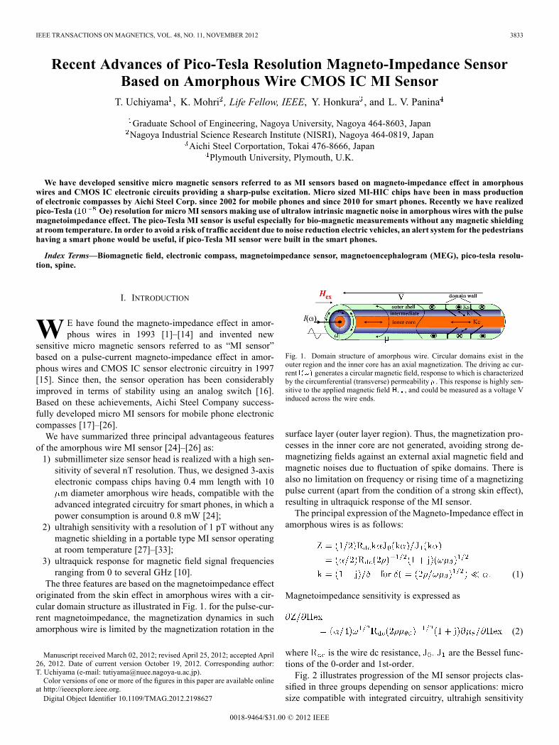
IEEE TRANSACTIONS ON MAGNETICS, VOL. 48, NO. 11, NOVEMBER 2012 3833 Recent Advances of Pico-Tesla Resolution Magneto-Impedance Sensor Based on Amorphous Wire CMOS IC MI Sensor T. Uchiyama , K. Mohri , Life Fellow, IEEE, Y. Honkura , and L. V. Panina Graduate School of Engineering, Nagoya University, Nagoya 464-8603, Japan Nagoya Industrial Science Research Institute (NISRI), Nagoya 464-0819, Japan Aichi Steel Corportation, Tokai 476-8666, Japan Plymouth University, Plymouth, U.K. We have developed sensitive micro magnetic sensors referred to as MI sensors based on magneto-impedance effect in amorphous wires and CMOS IC electronic circuits providing a sharp-pulse excitation. Micro sized MI-HIC chips have been in mass production of electronic compasses by Aichi Steel Corp. since 2002 for mobile phones and since 2010 for smart phones. Recently we have realized pico-Tesla ( Oe) resolution for micro MI sensors making use of ultralow intrinsic magnetic noise in amorphous wires with the pulse magnetoimpedance effect. The pico-Tesla MI sensor is useful especially for bio-magnetic measurements without any magnetic shielding at room temperature. In order to avoid a risk of traffic accident due to noise reduction electric vehicles, an alert system for the pedestrians having a smart phone would be useful, if pico-Tesla MI sensor were built in the smart phones. Index Terms—Biomagnetic field, electronic compass, magnetoimpedance sensor, magnetoencephalogram (MEG), pico-tesla resolu- tion, spine. I. INTRODUCTION W E have found the magneto-impedance effect in amor- phous wires in 1993 [1]–[14] and invented new sensitive micro magnetic sensors referred to as “MI sensor” based on a pulse-current magneto-impedance effect in amor- phous wires and CMOS IC sensor electronic circuitry in 1997 [15]. Since then, the sensor operation has been considerably improved in terms of stability using an analog switch [16]. Based on these achievements, Aichi Steel Company success- fully developed micro MI sensors for mobile phone electronic compasses [17]–[26]. We have summarized three principal advantageous features of the amorphous wire MI sensor [24]–[26] as: 1) submillimeter size sensor head is realized with a high sen- sitivity of several nT resolution. Thus, we designed 3-axis electronic compass chips having 0.4 mm length with 10 m diameter amorphous wire heads, compatible with the advanced integrated circuitry for smart phones, in which a power consumption is around 0.8 mW [24]; 2) ultrahigh sensitivity with a resolution of 1 pT without any magnetic shielding in a portable type MI sensor operating at room temperature [27]–[33]; 3) ultraquick response for magnetic field signal frequencies ranging from 0 to several GHz [10]. The three features are based on the magnetoimpedance effect originated from the skin effect in amorphous wires with a cir- cular domain structure as illustrated in Fig. 1. for the pulse-cur- rent magnetoimpedance, the magnetization dynamics in such amorphous wire is limited by the magnetization rotation in the Manuscript received March 02, 2012; revised April 25, 2012; accepted April 26, 2012. Date of current version October 19, 2012. Corresponding author: T. Uchiyama (e-mail: [email protected]). Color versions of one or more of the figures in this paper are available online at http://ieeexplore.ieee.org. Digital Object Identifier 10.1109/TMAG.2012.2198627 Fig. 1. Domain structure of amorphous wire. Circular domains exist in the outer region and the inner core has an axial magnetization. The driving ac cur- rent generates a circular magnetic field, response to which is characterized by the circumferential (transverse) permeability . This response is highly sen- sitive to the applied magnetic field , and could be measured as a voltage V induced across the wire ends. surface layer (outer layer region). Thus, the magnetization pro- cesses in the inner core are not generated, avoiding strong de- magnetizing fields against an external axial magnetic field and magnetic noises due to fluctuation of spike domains. There is also no limitation on frequency or rising time of a magnetizing pulse current (apart from the condition of a strong skin effect), resulting in ultraquick response of the MI sensor. The principal expression of the Magneto-Impedance effect in amorphous wires is as follows: (1) Magnetoimpedance sensitivity is expressed as (2) where is the wire dc resistance, are the Bessel func- tions of the 0-order and 1st-order. Fig. 2 illustrates progression of the MI sensor projects clas- sified in three groups depending on sensor applications: micro size compatible with integrated circuitry, ultrahigh sensitivity 0018-9464/$31.00 © 2012 IEEE
Transcript of Recent Advances of Pico-Tesla Resolution Magneto-Impedance ...
IEEE TRANSACTIONS ON MAGNETICS, VOL. 48, NO. 11, NOVEMBER 2012 3833
Recent Advances of Pico-Tesla Resolution Magneto-Impedance SensorBased on Amorphous Wire CMOS IC MI SensorT. Uchiyama , K. Mohri , Life Fellow, IEEE, Y. Honkura , and L. V. Panina
Graduate School of Engineering, Nagoya University, Nagoya 464-8603, JapanNagoya Industrial Science Research Institute (NISRI), Nagoya 464-0819, Japan
Aichi Steel Corportation, Tokai 476-8666, JapanPlymouth University, Plymouth, U.K.
We have developed sensitive micro magnetic sensors referred to as MI sensors based on magneto-impedance effect in amorphouswires and CMOS IC electronic circuits providing a sharp-pulse excitation. Micro sized MI-HIC chips have been in mass productionof electronic compasses by Aichi Steel Corp. since 2002 for mobile phones and since 2010 for smart phones. Recently we have realizedpico-Tesla ( Oe) resolution for micro MI sensors making use of ultralow intrinsic magnetic noise in amorphous wires with the pulsemagnetoimpedance effect. The pico-Tesla MI sensor is useful especially for bio-magnetic measurements without any magnetic shieldingat room temperature. In order to avoid a risk of traffic accident due to noise reduction electric vehicles, an alert system for the pedestrianshaving a smart phone would be useful, if pico-Tesla MI sensor were built in the smart phones.
Index Terms—Biomagnetic field, electronic compass, magnetoimpedance sensor, magnetoencephalogram (MEG), pico-tesla resolu-tion, spine.
I. INTRODUCTION
W E have found the magneto-impedance effect in amor-phous wires in 1993 [1]–[14] and invented new
sensitive micro magnetic sensors referred to as “MI sensor”based on a pulse-current magneto-impedance effect in amor-phous wires and CMOS IC sensor electronic circuitry in 1997[15]. Since then, the sensor operation has been considerablyimproved in terms of stability using an analog switch [16].Based on these achievements, Aichi Steel Company success-fully developed micro MI sensors for mobile phone electroniccompasses [17]–[26].We have summarized three principal advantageous features
of the amorphous wire MI sensor [24]–[26] as:1) submillimeter size sensor head is realized with a high sen-sitivity of several nT resolution. Thus, we designed 3-axiselectronic compass chips having 0.4 mm length with 10m diameter amorphous wire heads, compatible with theadvanced integrated circuitry for smart phones, in which apower consumption is around 0.8 mW [24];
2) ultrahigh sensitivity with a resolution of 1 pT without anymagnetic shielding in a portable type MI sensor operatingat room temperature [27]–[33];
3) ultraquick response for magnetic field signal frequenciesranging from 0 to several GHz [10].
The three features are based on the magnetoimpedance effectoriginated from the skin effect in amorphous wires with a cir-cular domain structure as illustrated in Fig. 1. for the pulse-cur-rent magnetoimpedance, the magnetization dynamics in suchamorphous wire is limited by the magnetization rotation in the
Manuscript received March 02, 2012; revised April 25, 2012; accepted April26, 2012. Date of current version October 19, 2012. Corresponding author:T. Uchiyama (e-mail: [email protected]).Color versions of one or more of the figures in this paper are available online
at http://ieeexplore.ieee.org.Digital Object Identifier 10.1109/TMAG.2012.2198627
Fig. 1. Domain structure of amorphous wire. Circular domains exist in theouter region and the inner core has an axial magnetization. The driving ac cur-rent generates a circular magnetic field, response to which is characterizedby the circumferential (transverse) permeability . This response is highly sen-sitive to the applied magnetic field , and could be measured as a voltage Vinduced across the wire ends.
surface layer (outer layer region). Thus, the magnetization pro-cesses in the inner core are not generated, avoiding strong de-magnetizing fields against an external axial magnetic field andmagnetic noises due to fluctuation of spike domains. There isalso no limitation on frequency or rising time of a magnetizingpulse current (apart from the condition of a strong skin effect),resulting in ultraquick response of the MI sensor.The principal expression of the Magneto-Impedance effect in
amorphous wires is as follows:
(1)
Magnetoimpedance sensitivity is expressed as
(2)
where is the wire dc resistance, are the Bessel func-tions of the 0-order and 1st-order.Fig. 2 illustrates progression of the MI sensor projects clas-
sified in three groups depending on sensor applications: microsize compatible with integrated circuitry, ultrahigh sensitivity
0018-9464/$31.00 © 2012 IEEE

3834 IEEE TRANSACTIONS ON MAGNETICS, VOL. 48, NO. 11, NOVEMBER 2012
Fig. 2. Amorphous wire and CMOS IC MI sensor projects based on three principal advantageous features.
with 1 pico-Tesla resolution and portability, and ultraquickresponse.
II. PICO-TESLA RESOLUTION MI SENSORS
A. Basic Electronic Circuitry of a Linear MI Sensor
We have constituted highly sensitive linear micro mag-netic-field sensors (MI sensors) inventing the pulse magne-toimpedance effect for tension-annealed amorphous wires withwound pick-up coils, combined with the CMOS IC multivi-brator circuit [15], [16], [20]–[24].The pick-up coil is wound on a zeromagnetostrictive (slightly
negative ) tension annealed amorphous CoFeSiBwire of 30 m in diameter (a-wire) for constitution of highlylinear magnetic sensors. The tension annealing makes the mag-netization in the surface layer (the outer shell domain) layingalong the circumferential (transversal) direction. For such mag-netic configuration, the voltage induced in the pick-up coil iszero if no magnetic field is applied and increases linearly withthe field. A principle MI sensor electronic circuit for magnetic-field detection is shown in Fig. 3. The square-wave voltage gen-erator (multivibrator: LMC555) produces a rectangular voltagetrain. The differential circuit (R1, C1) transfers the square wavevoltage into a positive sharp pulse. The current pulse train, witha width and a time interval , is applied to the a-wire as a car-rier using CMOS inverter (74AC04). The dc component (av-erage amount) of the current pulse train removes the domainwalls in the outer shell realizing a single domain and greatly re-ducing the magnetic noise and the hysteresis of magnetic-fieldsensing. A strong skin effect for the pulse magneto-impedancein a-wire is insured due to a quick rising time of around 100ns. Thus, such pulse excitation does not lead to any magneti-zation in the inner core domain generating spike domain fluc-tuation magnetic noises. For a helical static magnetization in-duced with a dc magnetic field applied along the a-wire length
Fig. 3. Basic electronics for magnetic field sensor. A linear MI sensor basedon the pulse magneto-impedance in an amorphous wire with pickup coil. ispulse current to magnetize the amorphous wire element and is an inducedvoltage at the pick-up coil.
direction, the pulse current passing through the wire inducesa coil pulse voltage the height of which in the first pulseonly is proportional to the applied dc magnetic field . Theanalog switch (SW:74HC4066) picks up only the first pulse inthe induced voltage waveform cutting following noise oscilla-tory wave, and also stabilizes the sensor circuit operation withits inner resistance. The first pulse is converted to a dc voltage
using a low-pass filter circuit.In this experiment, we use a pulse current having the values
of and of 100 ns and 2.5 s, respectively. Considering thepeak value of the current pulse of approximately 100 mA,the dc bias current is estimated to be 4 mA. Thisgenerates circumferential dc bias filed of
42 A/m, that is larger than the circumferential coercive force ofCoFeSiB a-wires [24]. Therefore, the circumferential bias mag-netic field could eliminate circular domain structure to decreasemagnetic noise due to wall motion. It has been pointed out that

UCHIYAMA et al.: RECENT ADVANCES OF PICO-TESLA RESOLUTION MAGNETO-IMPEDANCE SENSOR 3835
Fig. 4. versus characteristics of the MI sensor. Number of turns ofthe pickup coil is 300 and the length of the wire is 1 cm.
Fig. 5. Sensitivity dependence on number of pickup coil turns for a linearMI sensor after rectification. The wire length for each experiment is given insidethe round brackets.
the intrinsic magnetic field noise spectral density of the MI el-ement within a simplified model for single domain structure isexpressed as [34]
where is the temperature, is the magnetic damping constant,is Boltzman constant, is the gyro magnetic ratio, is the
saturation magnetization, is the diameter and is the length ofa wire element. Using typical parameters for Co-rich a-wires,we could estimate the value of . If magnetic noise is measuredover a band width of 1 Hz, a 1 cm length wire yields of ap-proximately 10 fT at the room temperature [34]. In other words,the best possible resolution of the MI sensor for magnetic fielddetection is in the range of a fT level (except the electronic cir-cuit noises).The field detection characteristics of MI sensor due to coil
pickup voltage are shown in Fig. 4. The length of the wire is1 cm and the number of coil turns is 300. A very high fielddetection sensitivity of about 66 kV/T and good linearity areobtained.The sensitivity dependence on number of turns is shown
in Fig. 5. The wire length for each experiment is given insidethe round brackets. The normalized sensitivity estimated from
Fig. 6. Induced voltage in the sensing coil (red line) and that in the referencecoil (blue line). The length of amorphous wire element is l cm and the numberof turns of a pickup coil is 500.
Fig. 7. Field detection characteristics of two pick up coils wound on an amor-phous wire for gradiometer. Open and close circles indicate the sensing coilrectification voltage and reference coil rectification voltage , respectively.
the slope of sensitivity vs. characteristics is 249 V/T/turns.In general, a high sensitivity in the range of 100 kV/T is ex-pected for a pico-tesla resolution magnetic field sensor. If wedetect 1 pT magnetic field with the help of the element havingthe sensitivity of 100 kV/T, the sensing element yields a 100nV signal. Assuming the frequency band of the system to be100 Hz, the signal of 100 nV corresponds to the voltage noiseof the instrumental amplifier having noise spectral density of10 nV/Hz . Furthermore, various background magnetic fieldssuch as the geomagnetic field and electric generator fields areadditional magnetic noises to sensor circuit noise that decreasethe signal-to-noise ratio in measurements. Therefore, the highsensitivity of MI sensor given by (2) along with minimized cir-cuit noises and other noises (common-mode noises, normal-mode noises and radiation noises) should be realized to achievepico-Tesla resolution without any magnetic shielding.
B. MI Gradiometer
In order to detect very weak magnetic field such as a biomag-netic field, we constructed MI gradiometer for the cancellationof background uniform noises such as the geomagnetic field.For this sensor head, the a-wire has two coils: a sensing coil anda reference coil. The distance between the two pick up coils isset to be 3 cm. The induced coil voltages from two pick upcoils are shown in Fig. 6. Two voltage waveforms well coincidewith each other. Fig. 7 illustrates the field detection character-istics using a 500- turns pick up coil, where is the rectified

3836 IEEE TRANSACTIONS ON MAGNETICS, VOL. 48, NO. 11, NOVEMBER 2012
Fig. 8. Diagram of the amplification circuit with auto-zero negative feedbackfor MI gradiometer. The analogue integrator is used for nulling the input offsetvoltage.
Fig. 9. Noise spectral density for MI gradiometer without any magnetic shied.After the subtraction voltage is amplified using an instrumentation amplifier
, the data are analyzed by a laptop computer.
voltage from the sensing coil and is from the reference coil.The sensitivity of the sensing coil is 130 kV/T and the differ-ence in sensitivity between and is within 1.5%. If a sub-traction voltage is used as an output voltage, theinfluence of a uniform background magnetic field can be almostneglected. When a local magnetic field (signal) is applied at theposition of the sensing coil, the subtraction voltage becomesproportional to the local field.The signal amplification circuit diagram for gradiometer is
shown in Fig. 8. In order to obtain a stable and high gain am-plification, the auto-zero circuit due to a negative feedback isemployed. Fig. 9 illustrates the noise spectral density of the MIgradiometer without any shielding. The operating frequency ofthe noise measurement is from 0.3 to 100 Hz. After the subtrac-tion voltage is amplified using an instrumentation amplifier
, the data are analyzed by a laptop computer. Thesampling rate and resolution of the AD convert system were 1ms and 14 bits, respectively. It is noted that the noise level ofless than 10 pT/Hz is achieved for frequencies from 2 to 20Hz and nearly 1 pT/Hz from 20 to 40 Hz. Fig. 10 illustratesthe designed frequency response of the MI gradiometer usingband pass filter and notch (band illumination) filter for the pur-pose of biomagenetic field measurement.
III. APPLICATIONS
A. Biomagentic Measurement
We have tried to measure magnetoencephalogram (MEG)using the pico-tesla resolution (pT) MI sensor under no shieldenvironment. The experimental set up for magnetic field mea-surement at back of the head is shown in Fig. 11. The sensor isset to measure a magnetic field perpendicular to the back
Fig. 10. Frequency characteristics of MI gradiometer for biomagneticmeasurement.
Fig. 11. Experimental set up for the magnetic measurement at back of the head.The MI sensor is set to measure the magnetic field perpendicular to backplane with the spacing mm.
Fig. 12. Magnetic field from the back left side of the head in (a) and background noise in (b). The eyes were opened during the first 8 s and then closedduring the following 8 s.
plane with the spacing mm. Fig. 12 illustrates the mea-surement results of time series of magnetic field for a seated50 years old man in comparison with background noise. Theeyes were opened during the first 8 s and then closed duringthe following 8 s. It is shown that the magnetic signal intensityfrom the back of the head is more than ten times larger thanthat of the background noise. According to the time series ofmagnetic field in Fig. 12(a), an alpha wave component (8–13Hz) seems to be enhanced after eyes are closed. In order toconfirm the activation of the alpha wave component due toeyes closing, we analyzed the frequency spectrum of the MEG.Fig. 13 illustrates the time dependence of , where ispartial over all of alpha wave in magnetic field and is partialover all of beta wave (14–30 Hz) in magnetic field. It is clearthat the ratio is increased after eyes closing.An advance measurement of a magnetic field from the spinal
cord has been attempted using a SQUID magnetometer [35],[36]. Recently, we have demonstrated that a biomagnetic fieldat the spine position can be measured using pTMI sensor as well

UCHIYAMA et al.: RECENT ADVANCES OF PICO-TESLA RESOLUTION MAGNETO-IMPEDANCE SENSOR 3837
Fig. 13. Time dependence of , where is partial over all of the alpha wave(8–13 Hz) and is partial over all of the beta wave (14–30 Hz) in magnetic fieldat back of the head.
Fig. 14. Simultaneously measured magnetic fields at the back of the head in (a)and at the spine position in (b) A subject quietly lies on his back for avoidanceof influence of the myogram on a flat wooden bed with eyes closing and twopT-MI gradiometer were set in a bed slit just under the position near the spinand back of the head.
Fig. 15. Spectrum analysis of both MEG and MSG for simultaneously mea-sured data with the use of pT-MI sensor. Both MEG and MSG have similarfrequency components.
as MEG. Fig. 14 illustrates the results of simultaneous measure-ment of magnetic fields using a pair of pTMI sensors at the backof the head (MEG) in (a) and at the spine (thoracic) position(MSG) in (b). A subject quietly lies on his back for avoidanceof influence of the myogram on a flat wooden bed with eyesclosed and two pT-MI gradiometer were set in a bed slit justunder the position near the spin and back of the head for the non-contact measurement. It appears to be some similarity betweenMEG and MSG due to presence of a similar frequency compo-nent. The frequency spectra for both magnetic fields of MEGand MSG are shown in Fig. 15. For that reason, we may expectto detect magnetic field due to neural activity of the spine posi-tion using pT MI sensor. We have been successful to evaluatethe arousal effect caused by a physiological magnetic stimula-tion using MSG signals for several subjects [28], [33].The biomageitic field in the living cell tissue has been
also investigated using pT-MI sensor. Fig. 16 illustrates theexperimental setup for the bio-magnetic field detection for a
Fig. 16. Experimental setup for measuring the active magnetic field in smoothmuscle preparations, which are dipped in the a circulatingwormed physiologicalsaline solution.
Fig. 17. Measured results of simultaneously detected time series of the electricand magnetic oscillatory signals for a guinea-pig stomach preparation.
living tissue, which is dipped in a circulating wormed physio-logical saline solution during the measurement. We have useda stomach musculature of the guinea pig as the preparation,which produces pace making electric activity with a ratherregular cycle even after isolation. The results of simultaneouslydetected time series of the electric and magnetic oscillatorysignals are shown in Fig. 17. reflects the extracellularelectrical field along the longitudinal direction of preparationsso that is proportional to the extracellular current flow.The sharp pulse waveform is considered to be due to Na -Ca exchange flow through the membrane ion channels andthe slow recovering parts are due to K and Cl flow. Thechanges in the magnetic field precisely synchronized with theextracellular electric activity. It seems that these two activitiesprovide different biological information. A phase lag of around2 s of the magnetic signal pulse against the electric signal pulseis found, which is considered to be due to a time lag of the ionflow on the tissue surface and the ion flow inside the tissue.
B. Other Applications
Hybrid cars are so quiet when operating in electric mode (EVmode) that they may pose a risk to the blind, small children, theelderly, runners, cyclists, and other pedestrians. A hybrid car isneeded to be 74 percent closer than a conventional car whenpeople could hear sounds and recognize from which directionthe car is approaching [37].The photograph of the hybrid car (Toyota Prius) detection ex-
periment usingmobile type pT-MI sensor is shown in Fig. 18(a),and the detected magnetic signal from the Prius at a distance of4 m is shown in Fig. 18(b). The frequency of the ac magnetic

3838 IEEE TRANSACTIONS ON MAGNETICS, VOL. 48, NO. 11, NOVEMBER 2012
Fig. 18. A hybrid car detection experiment using mobile type pT MI sensor.The experimental set up is shown in (a) and detected magnetic field in (b). Thefrequency of the ac magnetic field is 11 Hz and amplitude of the field is from 2to 5 nT.
field is 11 Hz and the amplitude of the field is from 2 to 5 nT. Itis estimate that pT-MI sensor can detect the approaching elec-tric vehicles from the distance of around 10 m. In order to avoida risk of traffic accident due to noise reduction electric vehicles,an alert system for the pedestrians having a smart phone wouldbe useful, if pT-MI sensor were built in smart phones.Various reliable security sensor systems such asMRI accident
protection, antishop lifting, and underground navigation systemare under development using the pT MI sensors. The pT MIsensors are also available for person-to-person direct magnetictelecommunications as hearing assistance for elderly.
IV. CONCLUSION
We have newly developed pico-Tesla ( Oe) resolutionmicro magnetic sensors using the amorphous wire and CMOSIC circuit on the basis of intrinsic ultralow magnetic noisesin amorphous wires with the pulse Magneto-Impedance effect.The pico-Tesla MI sensor is useful especially for bio-magneticmeasurements without any magnetic shielding at room temper-ature. In order to avoid a risk of traffic accident due to noisereduction electric vehicles, an alert system based on pico-TeslaMI sensor would be useful. Such system is suitable for buildingwithin a smart phone for easy use by pedestrians. Person-to-person direct magnetic telecommunications as hearing assistantfor elderly is proposed for a new application of pico-Tesla MIsensor.
ACKNOWLEDGMENT
This work is partly supported by Tateishi Science and Tech-nology Foundation, and Nakatani Foundation of ElectronicMeasuring Technology Advancement.
REFERENCES
[1] K. Mohri, “Application of amorphous magnetic wires to computer pe-ripherals,” Materials Science and Engineering A—Structural Mate-rials Properties Microstructure and Processing, vol. 185, no. 1–2, pp.141–145, 1994.
[2] L. V. Panina and K. Mohri, “Magneto-impedance effect in amorphouswires,” Appl. Phys. Lett., vol. 65, no. 9, pp. 1189–1191, 1994.
[3] L. V. Panina, K. Mohri, K. Bushida, and M. Noda, “Giant mag-neto-impedance and magneto-inductive effects in amorphous alloys,”J. Appl. Phys., vol. 76, no. 10, pp. 6198–6203, 1994.
[4] M. Noda, L. V. Panina, and K. Mohri, “Pulse response bistable mag-neto-impedance effect in amorphous wires,” IEEE Trans. Magn., vol.31, no. 6, pp. 3167–3169, Jun. 1995.
[5] T. Kitoh, K. Mohri, and T. Uchiyama, “Asymmetrical mag-neto-impedance effect in twisted amorphous wires for sensitivemagnetic sensors,” IEEE Trans. Magn., vol. 31, no. 6, pp. 3137–3139,Jun. 1995.
[6] K. Mohri, K. Bushida, M. Noda, H. Yoshida, L. V. Panina, and T.Uchiyama, “Magneto-impedance element,” IEEE Trans. Magn., vol.31, no. 4, pp. 2455–2460, Apr. 1995.
[7] K. Mohri, L. V. Panina, T. Uchiyama, M. Noda, and K. Bushida, “Sen-sitive and quick response micro magnetic sensor utilizing magneto-impedance in co-rich amorphous wires,” IEEE Trans. Magn., vol. 31,no. 2, pp. 1266–1275, Feb. 1995.
[8] L. V. Panina, K. Mohri, T. Uchiyama, M. Noda, and K. Bushida,“Giant magneto-impedance in co-rich amorphous wires and films,”IEEE Trans. Magn., vol. 31, no. 2, pp. 1249–1260, Feb. 1995.
[9] L. V. Panina and K.Mohri, “Effect of magnetic structure on giant mag-neto-impedance in co-rich amorphous alloys,” J. Mag. Mag. Mat., vol.158, pp. 137–140, 1996.
[10] V. P. Paramanov, A. S. Antonov, A. N. Lagarikov, L. V. Panina, and K.Mohri, “High frequency (1–1200 MHz) magneto-impeance in co-richamorphous wires,” J. Appl. Phys., vol. 79, no. 8, pp. 6532–6534, 1996.
[11] L. V. Panina, K. Mohri, and T. Uchiyama, “Giant magneto-impedancein amorphous wire, single layer film and sandwich film,” Physica A,vol. 241, no. 1–2, pp. 429–438, 1997.
[12] T. Yoshinaga, S. Furukawa, and K. Mohri, “Magneto-impedance effectin etched thin amorphous wires,” IEEE Trans. Magn., vol. 35, no. 5, pp.3613–3615, May 1999.
[13] L. V. Panina, K. Mohri, and D. P. Makhnovskiy, “Mechanism of asym-metrical magneto-impedance in amorphous wires,” J. Appl. Phys., vol.85, no. 8, pp. 5444–5446, 1999.
[14] K. Kawashima, I. Ogasawara, S. Ueno, and K. Mohri, “Asymmetricalmagneto-impedance effect in torsion annealed co-rich amorphous wirefor MI micro magnetic sensors,” IEEE Trans. Magn., vol. 35, no. 5, pp.3610–3612, May 1999.
[15] T. Kanno, K. Mohri, T. Yagi, T. Uchiyama, and L. P. Shen, “Amor-phous wire MI micro sensor using CMOS IC multivibrator,” IEEETrans. Magn., vol. 33, no. 5, pp. 3353–3360, May 1997.
[16] N. Kawajiri, M. Kakabayashi, C. M. Cai, K. Mohri, and T. Uchiyama,“Highly stable MI micro sensor using CMOS IC multivibrator withsynchronous rectification,” IEEE Trans. Magn., vol. 35, no. 5, pp.3667–3669, May 1999.
[17] T. Uchiyama, K. Mohri, H. Itoh, K. Nakashima, J. Ouchi, and Y. Sudo,“Car traffic monitoring system using MI sensor buil-in disk set on theroad,” IEEE Trans. Magn., vol. 36, no. 5, pp. 3670–3672, May 2000.
[18] C. M. Cai, K. Mohri, Y. Honkura, and M. Yamamoto, “Improved pulsecarrier MI effect by flash anneal of amorphous wires and FM wire-less CMOS IC torque sensor,” IEEE Trans. Magn., vol. 37, no. 4, pp.2038–2041, Apr. 2001.
[19] C. M. Cai, K. Usami, M. Hayashi, and K. Mohri, “Frequency modula-tion type MI sensor using amorphous wire and CMOS inverter multi-vibrator,” IEEE Trans. Magn., vol. 40, no. 1, pp. 161–163, Jan. 2004.
[20] K. Mohri, T. Uchiyama, and L. V. Panina, “Magneto-impedance (MI)micro magnetic sensors—Principle and applications,” Transducers,vol. 1, pp. 76–79, 1999.

UCHIYAMA et al.: RECENT ADVANCES OF PICO-TESLA RESOLUTION MAGNETO-IMPEDANCE SENSOR 3839
[21] K. Mohri, T. Uchiyama, L. P. Shen, C. M. Cai, and L. V. Panina,“Sensitive micro magnetic sensor family utilizing magneto-impedance(MI) and stress-impedance (SI) effects for intelligent measurementsand controls,” Sensors Actuators, vol. A91, pp. 85–90, 2001.
[22] K. Mohri, T. Uchiyama, L. P. Shen, C. M. Cai, and L. V. Panina,“Amorphous wire and CMOS IC based sensitive micro magnetic sen-sors (MI sensor and SI sensor) for intelligent measurements and con-trols,” J. Mag. Mag. Mat., vol. 249, pp. 351–356, 2002.
[23] K. Mohri, T. Uchiyama, L. P. Shen, C. M. Cai, L. V. Panina, Y.Honkura, and M. Yamamoto, “Amorphous wire and CMOS IC basedsensitive micromagnetic sensors utilizing magneto-impedance (MI)and stress-impedance (SI) effects,” IEEE Trans. Magn., vol. 38, no. 5,pp. 3063–3068, May 2002.
[24] K. Mohri and Y. Honkura, “Amorphous wire and CMOS IC basedmagneto-impedance sensors—Origin, topics, and future,” Sensor Lett.,vol. 5, pp. 267–270, 2007.
[25] K. Mohri, F. B. Humphrey, L. V. Panina, Y. Honkura, J. Yamasaki, T.Uchiyama, and M. Hirami, “Advances of amorphous wire magneticsover 27 years,” Phys. Status Solidi A, vol. 206, no. 4, pp. 601–607,2009.
[26] K. Mohri, Y. Honkura, L. V. Panina, and T. Uchiyama, “SuperMI sensor—Recent advances of amorphous wire CMOS IC mag-neto-impedance sensor,” J. Nanoscience and Nanotechnology 2012,RTNSA issue, in press.
[27] T. Uchiyama, S. Nakayama, K. Mohri, and K. Bushida, “Biomagneticfield detection using very high sensitivity magneto-impedance sensorsfor medical applications,” Phys. Status Solidi A, vol. 206, no. 4, pp.639–643, 2009.
[28] K. Mohri, T. Uchiyama, M. Yamada, T. Watanabe, Y. Inden, T. Kato,and S. Iwata, “Arousal effect of physiological magnetic stimulation onelder person’s spine for prevention of drowsiness during car driving,”IEEE Trans. Magn., vol. 47, no. 10, pp. 3066–3069, Oct. 2011.
[29] K. Mohri, Y. Nakamura, T. Uchiyama, Y. Mohri, Yu. Mohri, and Y.Inden, “Sensing of human micro-vibration transmitted along solidusing pico-tesla magneto-impedance sensor (pT-MI sensor),” PiersOnline, vol. 6, no. 2, pp. 161–164, 2010.
[30] T. Uchiyama, K. Mohri, and S. Nakayama, “Measurement of sponta-neous oscillatory magnetic field of guinea-pig smooth muscle prepa-ration using pico-tesla resolution amorphous wire magneto-impedancesensor,” IEEE Trans. Magn., vol. 47, no. 10, pp. 3066–3069, Oct. 2011.
[31] K.Mohri, M. Fukushima, Y.Mohri, and Yu.Mohri, “Detection of mag-netization of 6 Hz, 10 T magnetic field applied water using PT-MIsensor,” Piers Online, vol. 6, no. 2, pp. 145–148, 2010.
[32] N. Hamada, A. Shimode, T. Kawano, H. Arakawa, M. Yamamoto, andY. Honkura, “Development of low noise GMI sensor and its applica-tions,” in Proc. Intermag, 2011, FF-08.
[33] K. Mohri, T. Uchiyama, M. Yamada, Y. Mohri, K. Endo, T. Suzuki,and Y. Inden, “Physiological magnetic stimulation for arousal of eldercar driver evaluated with electro-encephalogram and spine magneticfield,” in Proc. Intermag, 2012, ED-04.
[34] L. G. C. Melo, D. Menard, A. Yelon, L. Ding, S. Saez, and C.Dolabdjian, “Optimization of the magnetic noise and sensitivityof giant magnetoimpedance sensors,” J. Appl. Phys., vol. 103, pp.033903-1–03303-6, 2008.
[35] Y. Adachi, J. Kawai,M.Miyamoto, H. Ogata,M. Tomori, S. Kawabata,T. Sato, and G. Uehara, “A SQUID system for measurement of spinalcord evoked field of supine subjects,” IEEE Trans. Appl. Supercond.,vol. 19, no. 3, pp. 861–866, Jun. 2009.
[36] S. Tomizawa, S. Kawabata, S. Komori, H. Hoshino, Y. Fukuoka, andK. Shinomiya, “Evaluation of segmental spinal cord evoked magneticfield after sciatic nerve stimulation,” Clin. Neurophys., vol. 119, no. 5,pp. 1111–1118, 2008.
[37] S. Simpson, “Are hybrid cars too quiet to be safe for pedestrians?,” Sci.Amer., Jul. 30, 2008.
View publication statsView publication stats