Receiver Testing to Third Generation Standards Testing (a.k.a “Jitter Tolerance”) Review •...
39
Receiver Testing to Third Generation Standards Jim Dunford, October 2011
Transcript of Receiver Testing to Third Generation Standards Testing (a.k.a “Jitter Tolerance”) Review •...

Receiver Testing to Third Generation StandardsJim Dunford, October 2011
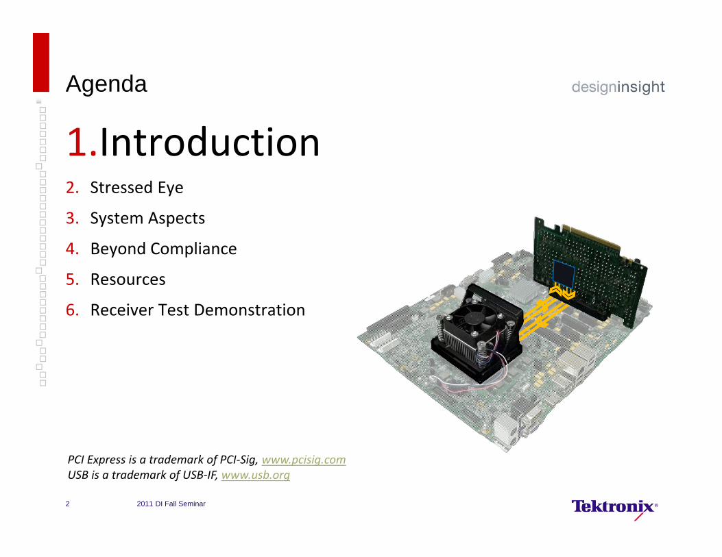
Agenda
1.Introduction2. Stressed Eye
3. System Aspects
4. Beyond Compliance
5. Resources
6. Receiver Test Demonstration
PCI Express is a trademark of PCI‐Sig, www.pcisig.comUSB is a trademark of USB‐IF, www.usb.org
2011 DI Fall Seminar2
Introduction
Host or Root ComplexHost or Root Complex
Add‐In Card
Motherboard
End PointEnd Point
PCI Express Gen 3 LinkPCI Express Gen 3 Link
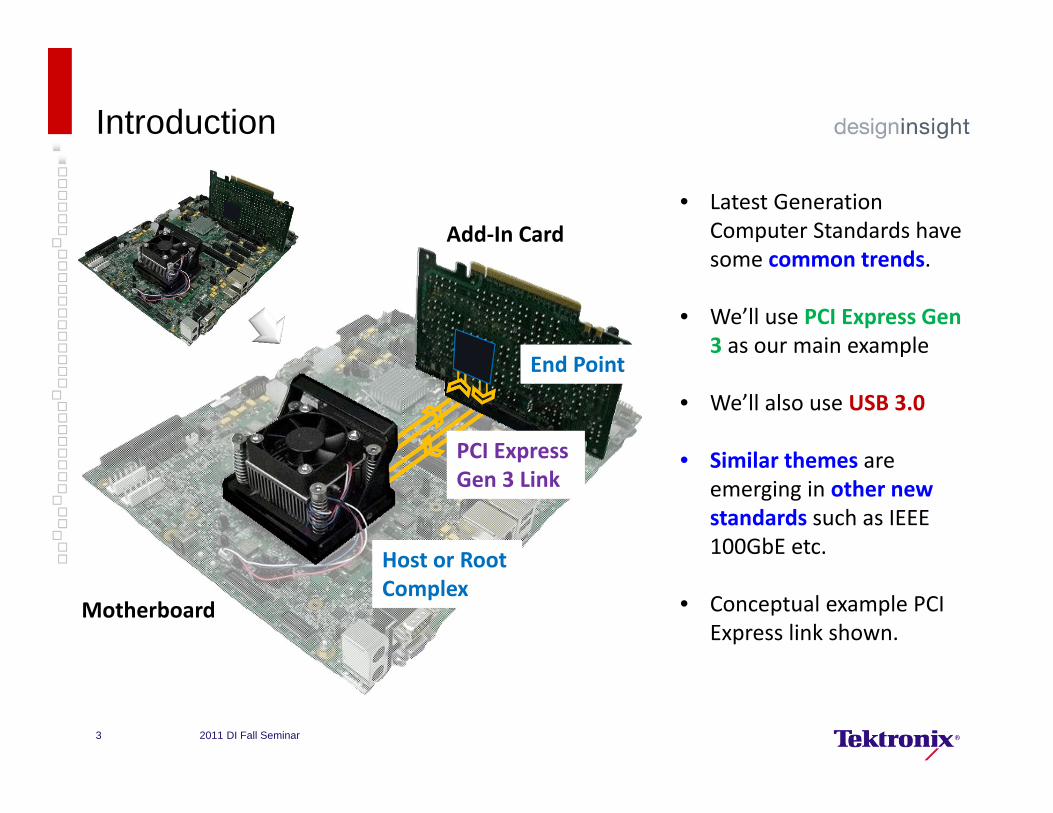
• Latest Generation Computer Standards have some common trends.
• We’ll use PCI Express Gen 3 as our main example
• We’ll also use USB 3.0
• Similar themes are emerging in other new standards such as IEEE 100GbE etc.
• Conceptual example PCI Express link shown.
2011 DI Fall Seminar3
Introduction - Basics
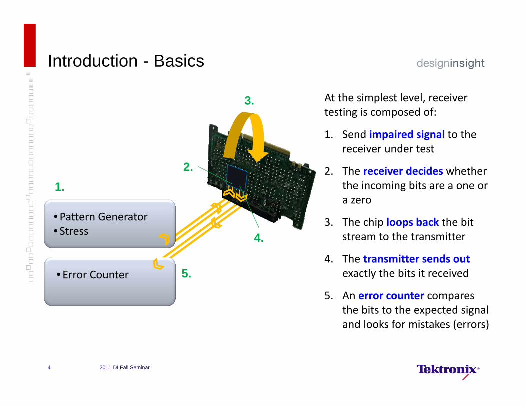
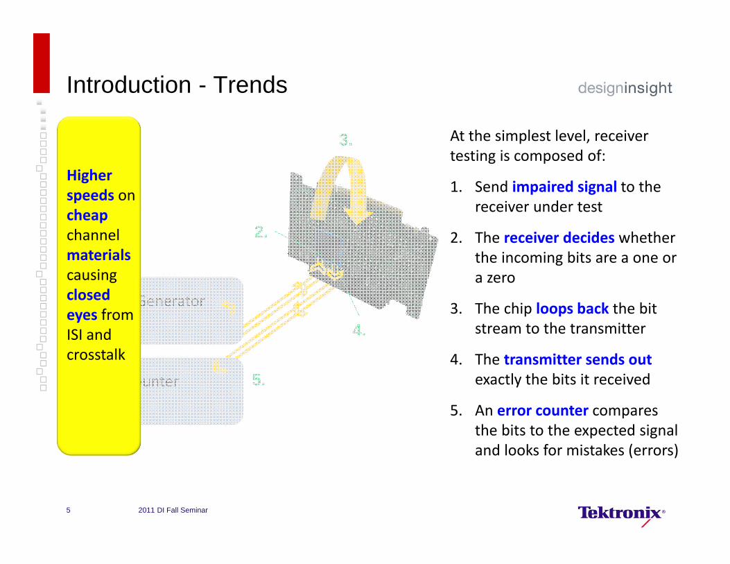
At the simplest level, receiver testing is composed of:
1. Send impaired signal to the receiver under test
2. The receiver decides whether the incoming bits are a one or a zero
3. The chip loops back the bit stream to the transmitter
4. The transmitter sends out exactly the bits it received
5. An error counter compares the bits to the expected signal and looks for mistakes (errors)
•Pattern Generator• Stress
• Error Counter
1.2.
3.
4.
5.
2011 DI Fall Seminar4
Introduction - Trends
•Pattern Generator• Stress
• Error Counter
1.2.
3.
4.
5.
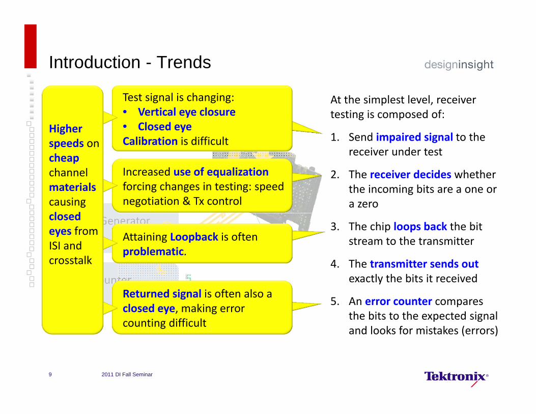
Higher speeds on cheapchannel materialscausing closed eyes from ISI and crosstalk
2011 DI Fall Seminar5
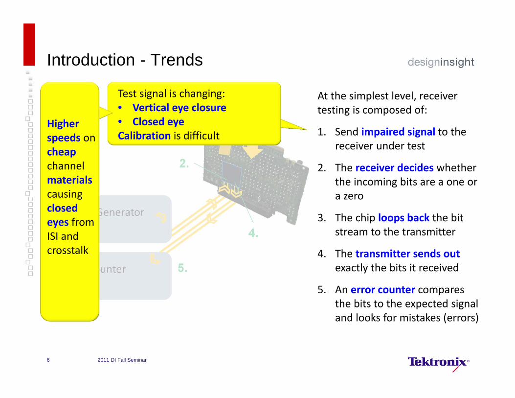
At the simplest level, receiver testing is composed of:
1. Send impaired signal to the receiver under test
2. The receiver decides whether the incoming bits are a one or a zero
3. The chip loops back the bit stream to the transmitter
4. The transmitter sends out exactly the bits it received
5. An error counter compares the bits to the expected signal and looks for mistakes (errors)
Introduction - Trends
•Pattern Generator• Stress
• Error Counter
1.2.
3.
4.
5.
Test signal is changing:• Vertical eye closure• Closed eyeCalibration is difficult
Higher speeds on cheapchannel materialscausing closed eyes from ISI and crosstalk
2011 DI Fall Seminar6
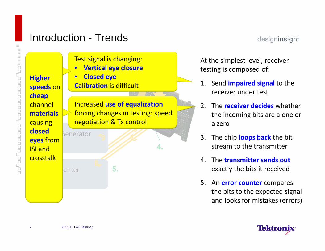
At the simplest level, receiver testing is composed of:
1. Send impaired signal to the receiver under test
2. The receiver decides whether the incoming bits are a one or a zero
3. The chip loops back the bit stream to the transmitter
4. The transmitter sends out exactly the bits it received
5. An error counter compares the bits to the expected signal and looks for mistakes (errors)
Introduction - Trends
•Pattern Generator• Stress
• Error Counter
1.2.
3.
4.
5.
Test signal is changing:• Vertical eye closure• Closed eyeCalibration is difficult
Increased use of equalization forcing changes in testing: speed negotiation & Tx control
Higher speeds on cheapchannel materialscausing closed eyes from ISI and crosstalk
2011 DI Fall Seminar7
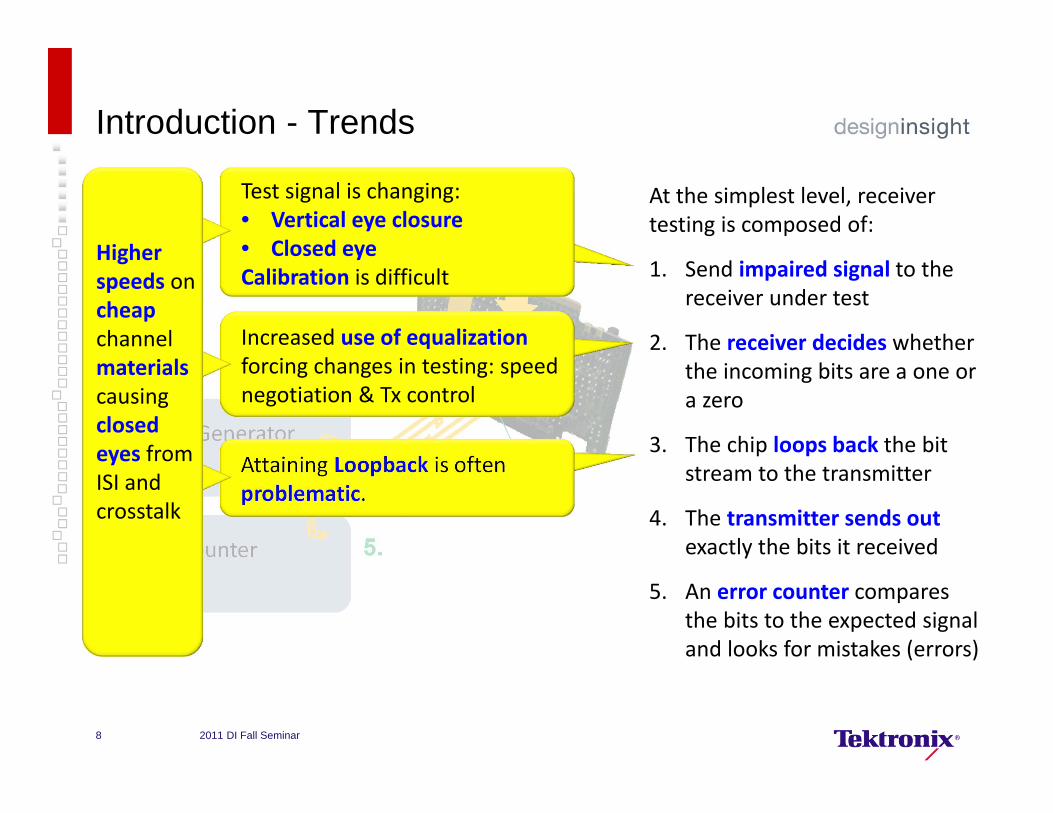
At the simplest level, receiver testing is composed of:
1. Send impaired signal to the receiver under test
2. The receiver decides whether the incoming bits are a one or a zero
3. The chip loops back the bit stream to the transmitter
4. The transmitter sends out exactly the bits it received
5. An error counter compares the bits to the expected signal and looks for mistakes (errors)
Introduction - Trends
•Pattern Generator• Stress
• Error Counter
1.2.
3.
4.
5.
Attaining Loopback is often problematic.
Test signal is changing:• Vertical eye closure• Closed eyeCalibration is difficult
Increased use of equalization forcing changes in testing: speed negotiation & Tx control
Higher speeds on cheapchannel materialscausing closed eyes from ISI and crosstalk
2011 DI Fall Seminar8
At the simplest level, receiver testing is composed of:
1. Send impaired signal to the receiver under test
2. The receiver decides whether the incoming bits are a one or a zero
3. The chip loops back the bit stream to the transmitter
4. The transmitter sends out exactly the bits it received
5. An error counter compares the bits to the expected signal and looks for mistakes (errors)
Introduction - Trends
•Pattern Generator• Stress
• Error Counter
1.2.
3.
4.
5.Returned signal is often also a closed eye, making error counting difficult
Attaining Loopback is often problematic.
Test signal is changing:• Vertical eye closure• Closed eyeCalibration is difficult
Increased use of equalization forcing changes in testing: speed negotiation & Tx control
Higher speeds on cheapchannel materialscausing closed eyes from ISI and crosstalk
2011 DI Fall Seminar9
At the simplest level, receiver testing is composed of:
1. Send impaired signal to the receiver under test
2. The receiver decides whether the incoming bits are a one or a zero
3. The chip loops back the bit stream to the transmitter
4. The transmitter sends out exactly the bits it received
5. An error counter compares the bits to the expected signal and looks for mistakes (errors)
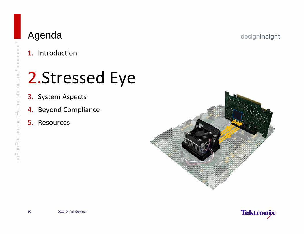
Agenda
1. Introduction
2.Stressed Eye3. System Aspects
4. Beyond Compliance
5. Resources
2011 DI Fall Seminar10
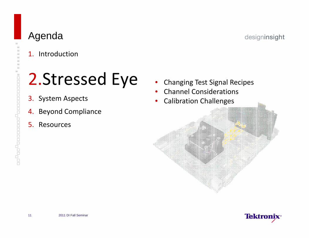
Agenda
1. Introduction
2.Stressed Eye3. System Aspects
4. Beyond Compliance
5. Resources
• Changing Test Signal Recipes• Channel Considerations• Calibration Challenges
2011 DI Fall Seminar11

Pattern Generator
Pattern High Speed Amplifiers
etc.
Stress Impairments
Receiver Testing (a.k.a “Jitter Tolerance”) Review
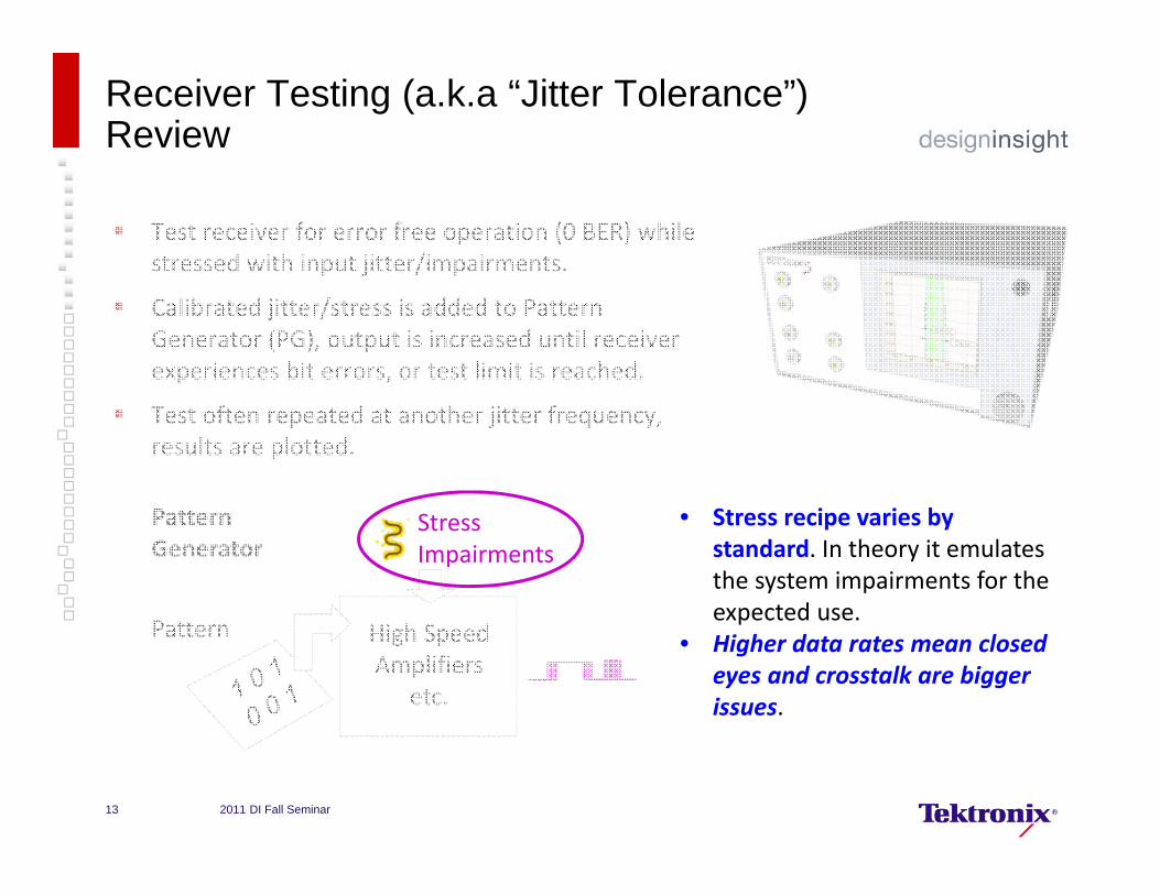
Test receiver for error free operation (0 BER) while stressed with input jitter/impairments.
Calibrated jitter/stress is added to Pattern Generator (PG), output is increased until receiver experiences bit errors, or test limit is reached.
Test often repeated at another jitter frequency, results are plotted.
2011 DI Fall Seminar12
Test receiver for error free operation (0 BER) while stressed with input jitter/impairments.
Calibrated jitter/stress is added to Pattern Generator (PG), output is increased until receiver experiences bit errors, or test limit is reached.
Test often repeated at another jitter frequency, results are plotted.
Pattern Generator
Pattern High Speed Amplifiers
etc.
Receiver Testing (a.k.a “Jitter Tolerance”) Review
• Stress recipe varies by standard. In theory it emulates the system impairments for the expected use.
• Higher data rates mean closed eyes and crosstalk are bigger issues.
Stress Impairments
2011 DI Fall Seminar13
Generic Stress Recipe
Tx Eq
PRBSGen
RJSource
SJSource
Channel Test Equipment
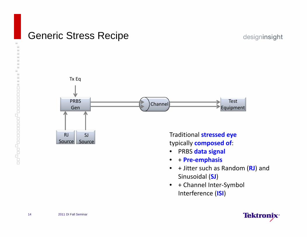
Traditional stressed eye typically composed of:• PRBS data signal• + Pre‐emphasis• + Jitter such as Random (RJ) and
Sinusoidal (SJ)• + Channel Inter‐Symbol
Interference (ISI)
Traditional stressed eye typically composed of:• PRBS data signal• + Pre‐emphasis• + Jitter such as Random (RJ) and
Sinusoidal (SJ)• + Channel Inter‐Symbol
Interference (ISI)
2011 DI Fall Seminar14

Generic Stress Recipe
Tx Eq
PRBSGen
RJSource
SJSource
Channel Test Equipment
Traditional stressed eye typically composed of:• PRBS data signal• + Pre‐emphasis• + Jitter such as Random (RJ) and
Sinusoidal (SJ)• + Channel Inter‐Symbol
Interference (ISI)
Traditional stressed eye typically composed of:• PRBS data signal• + Pre‐emphasis• + Jitter such as Random (RJ) and
Sinusoidal (SJ)• + Channel Inter‐Symbol
Interference (ISI)
Resulting Stressed Eye
ISI
Clean Signal
Pre‐Emphasis
RJ SJ
1.
2.
3. 4.
5.
6.
2011 DI Fall Seminar15
USB 3.0 Stress Recipe
Tx Eq
PRBSGen
RJSource
SJSource
Channel Test Equipment
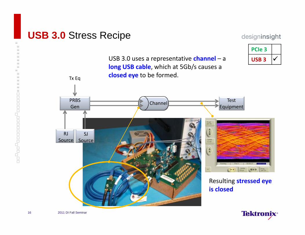
USB 3.0 uses a representative channel – a long USB cable, which at 5Gb/s causes a closed eye to be formed.
USB 3.0 uses a representative channel – a long USB cable, which at 5Gb/s causes a closed eye to be formed.
Resulting stressed eye is closedResulting stressed eye is closed
PCIe 3
USB 3
2011 DI Fall Seminar16
PCIe Gen 3 Stress Recipe - Overview
Tx Eq
8G PRBSGen
RJSource
SJSource
Combiner
DiffInterference
Cal.Channel
ReplicaChannel
Test Equipment
CMInterference
Post‐processing
Eye HeightAdjust
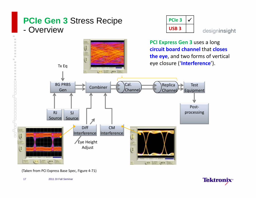
(Taken from PCI Express Base Spec, Figure 4‐71)
PCI Express Gen 3 uses a long circuit board channel that closes the eye, and two forms of vertical eye closure (‘Interference’).
PCI Express Gen 3 uses a long circuit board channel that closes the eye, and two forms of vertical eye closure (‘Interference’).
PCIe 3
USB 3
2011 DI Fall Seminar17
PCIe Gen 3 Stress Recipe - Interference
Tx Eq
8G PRBSGen
RJSource
SJSource
CombinerCal.Channel
ReplicaChannel
Test Equipment
Post‐processing
DiffInterference
CMInterference
EH Adjust
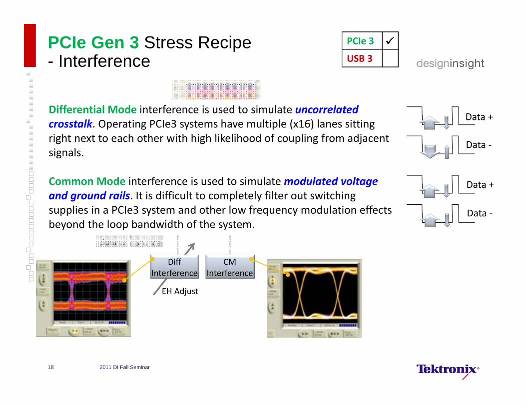
Differential Mode interference is used to simulate uncorrelated crosstalk. Operating PCIe3 systems have multiple (x16) lanes sitting right next to each other with high likelihood of coupling from adjacent signals.
Common Mode interference is used to simulate modulated voltage and ground rails. It is difficult to completely filter out switching supplies in a PCIe3 system and other low frequency modulation effects beyond the loop bandwidth of the system.
Data +
Data ‐
Data +
Data ‐
PCIe 3
USB 3
2011 DI Fall Seminar18
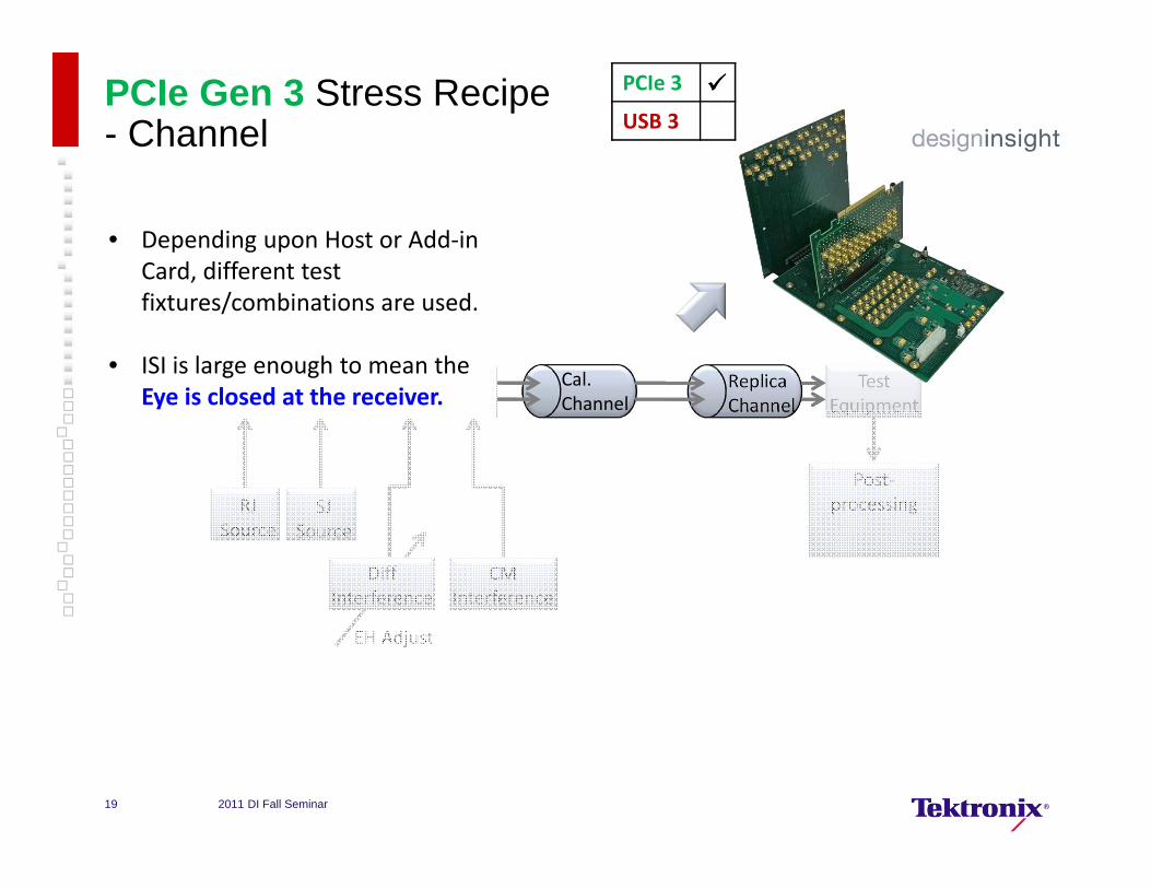
PCIe Gen 3 Stress Recipe- Channel
Tx Eq
8G PRBSGen
RJSource
SJSource
Combiner
DiffInterference
Test Equipment
CMInterference
Post‐processing
EH Adjust
Cal.Channel
ReplicaChannel
• Depending upon Host or Add‐in Card, different test fixtures/combinations are used.
• ISI is large enough to mean the Eye is closed at the receiver.
• Depending upon Host or Add‐in Card, different test fixtures/combinations are used.
• ISI is large enough to mean the Eye is closed at the receiver.
PCIe 3
USB 3
2011 DI Fall Seminar19
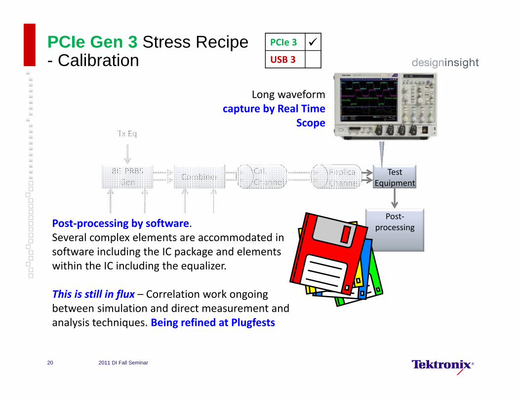
PCIe Gen 3 Stress Recipe- Calibration
Tx Eq
8G PRBSGen
RJSource
SJSource
Combiner
DiffInterference
CMInterference
EH Adjust
Cal.Channel
ReplicaChannel
Test Equipment
Post‐processingPost‐processing by software.
Several complex elements are accommodated in software including the IC package and elements within the IC including the equalizer.
This is still in flux – Correlation work ongoing between simulation and direct measurement and analysis techniques. Being refined at Plugfests
Post‐processing by software.Several complex elements are accommodated in software including the IC package and elements within the IC including the equalizer.
This is still in flux – Correlation work ongoing between simulation and direct measurement and analysis techniques. Being refined at Plugfests
PCIe 3
USB 3
Long waveform capture by Real Time
Scope
Long waveform capture by Real Time
Scope
2011 DI Fall Seminar20

USB 3.0 Stress Recipe- Calibration
Tx Eq
PRBSGen
RJSource
SJSource
Channel
Long waveform capture by Real Time
Scope
Long waveform capture by Real Time
Scope
Test Equipment
Post‐processing
Mature standard with fully automated
solutions for stress calibration and good
correlation
Mature standard with fully automated
solutions for stress calibration and good
correlation
2011 DI Fall Seminar21
PCIe 3
USB 3

PCIe Gen 3: Example Add-In Card Stress Calibration
In Out+
‐
+
‐
To RT Scope for calibration
SI Combiner
Gen 3 CBB Riser
Gen 3 CBB (Main)
Rx Lane 0
Tx Lane 0
Last Cal. details being refined. This setup beingsuccessfully used at Plugfests
Last Cal. details being refined. This setup beingsuccessfully used at Plugfests
PCIe 3
USB 3
2011 DI Fall Seminar22
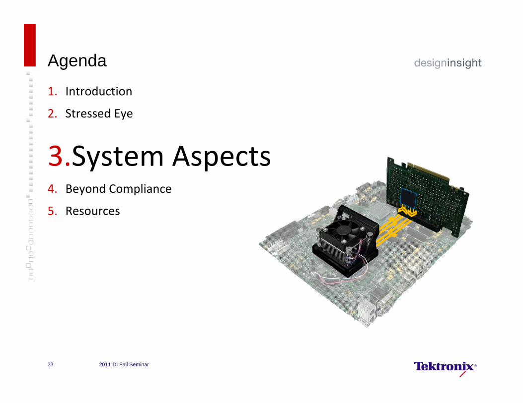
Agenda
1. Introduction
2. Stressed Eye
3.System Aspects4. Beyond Compliance
5. Resources
2011 DI Fall Seminar23
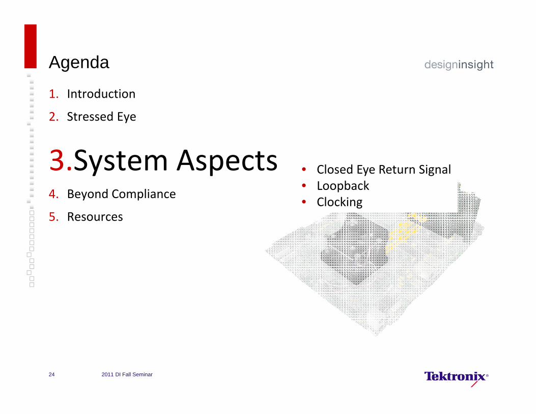
Agenda
1. Introduction
2. Stressed Eye
3.System Aspects4. Beyond Compliance
5. Resources
• Closed Eye Return Signal• Loopback• Clocking
2011 DI Fall Seminar24
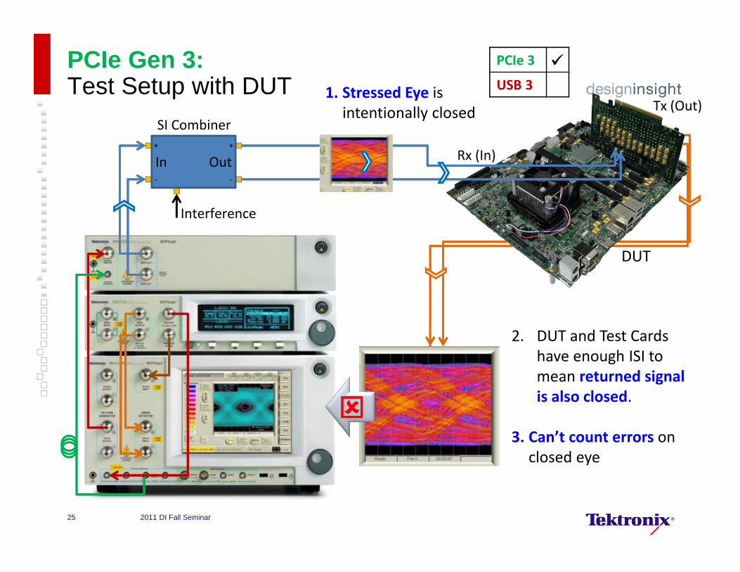
PCIe Gen 3: Test Setup with DUT
In Out+
‐
+
‐
SI CombinerTx (Out)
Rx (In)
DUT
2. DUT and Test Cards have enough ISI to mean returned signal is also closed.
3. Can’t count errors on closed eye
PCIe 3
USB 3
1. Stressed Eye is intentionally closed
Interference
2011 DI Fall Seminar25

In Out+
‐
+
‐
Repeater
•Use external ‘eye opener’ equalizer to allow error counting
• E.g. National Semiconductor DS100BR410EVK‐4www.national.com/
PCIe Gen 3: Test Setup with DUT & Eye Opener
PCIe 3
USB 3
2011 DI Fall Seminar26
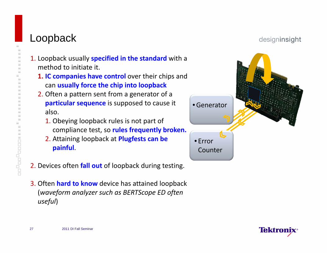
Loopback
1. Loopback usually specified in the standard with a method to initiate it.1. IC companies have control over their chips and can usually force the chip into loopback
2. Often a pattern sent from a generator of a particular sequence is supposed to cause it also.1. Obeying loopback rules is not part of compliance test, so rules frequently broken.
2. Attaining loopback at Plugfests can be painful.
2. Devices often fall out of loopback during testing.
3. Often hard to know device has attained loopback (waveform analyzer such as BERTScope ED often useful)
•Generator
• ErrorCounter
2011 DI Fall Seminar27

Loopback – USB3
• USB3 specifies a sequence of bits to initiate it that forms a low frequency square wave (“LFPS”).
• Frequently test equipment will use a separate generator for loopback initiation which switches out once loopback is attained.
LFPS
DUT
Tek USB Switch with
LFPS
•Generator
• ErrorCounter
Tek USB Software Loopback Control
PCIe 3
USB 3
2011 DI Fall Seminar28
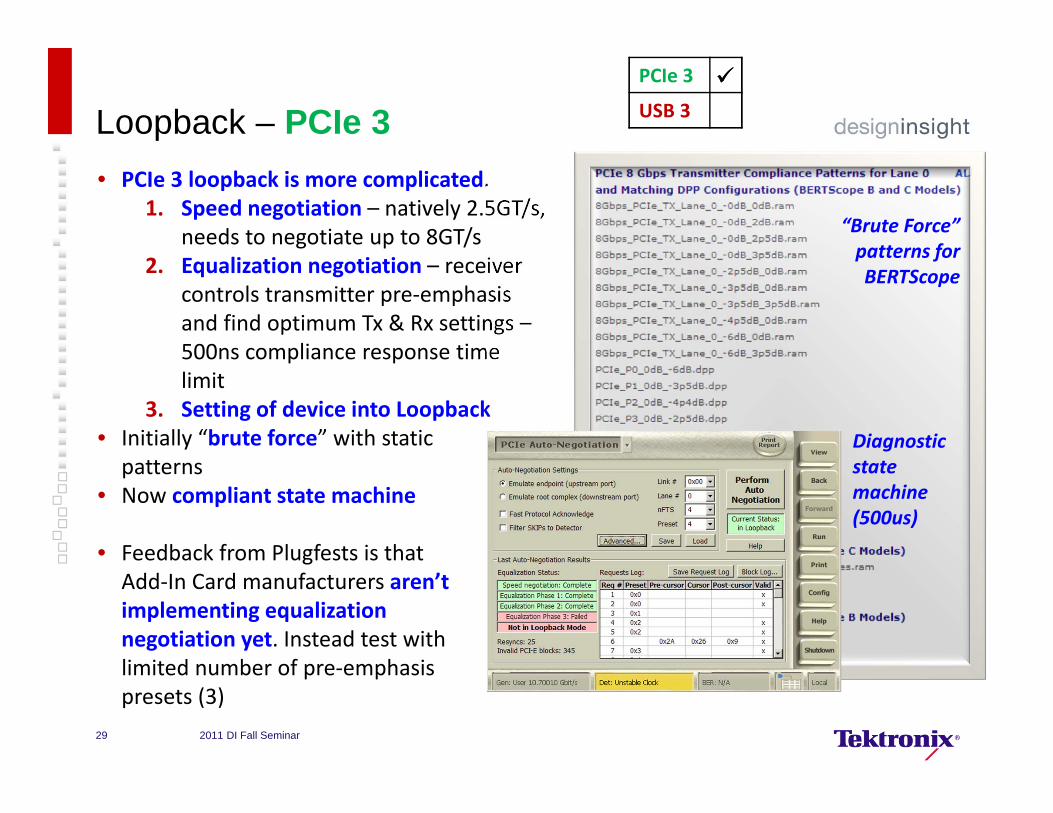
Loopback – PCIe 3
•Generator
• ErrorCounter
PCIe 3
USB 3
• PCIe 3 loopback is more complicated.1. Speed negotiation – natively 2.5GT/s,
needs to negotiate up to 8GT/s2. Equalization negotiation – receiver
controls transmitter pre‐emphasis and find optimum Tx & Rx settings –500ns compliance response time limit
3. Setting of device into Loopback• Initially “brute force” with static patterns
• Now compliant state machine
• Feedback from Plugfests is that Add‐In Card manufacturers aren’timplementing equalization negotiation yet. Instead test withlimited number of pre‐emphasispresets (3)
“Brute Force” patterns for BERTScope
Diagnostic state machine (500us)
2011 DI Fall Seminar29

Clocking – PCIe3
PCIe 3
USB 3
1. 100 MHz Clock
2. 100 MHz Clock
3. 8 GT/s Data
• Add‐in cards take in a 100 MHz clock.• This is straight forward, test equipment usually provides sub‐rate clock easily (1).
• Motherboards are harder – DUT provides 100 MHz clock (2), but test equipment needs 8 GHz clock.• Could derive clock from 8 GT/s data signal using clock recovery (3). Device margins are small enough to mean worries about extra jitter added by the transmitter.
• Ideally use well controlled clock multiplier from system 100 MHz clock.
2011 DI Fall Seminar30

Clocking
• Practical setup used for Plugfests to multiply system clock (2)
• Clock multiplied in two stages to preserve compliant loop bandwidth & peaking
PCIe 3
USB 3
2. 100 MHz Clock
100 MHz RefFrom CLB
8GHz to BERTScopeGenerator Ext. Clock
In
8GHz to BERTScopeDetector Clock In
2011 DI Fall Seminar31
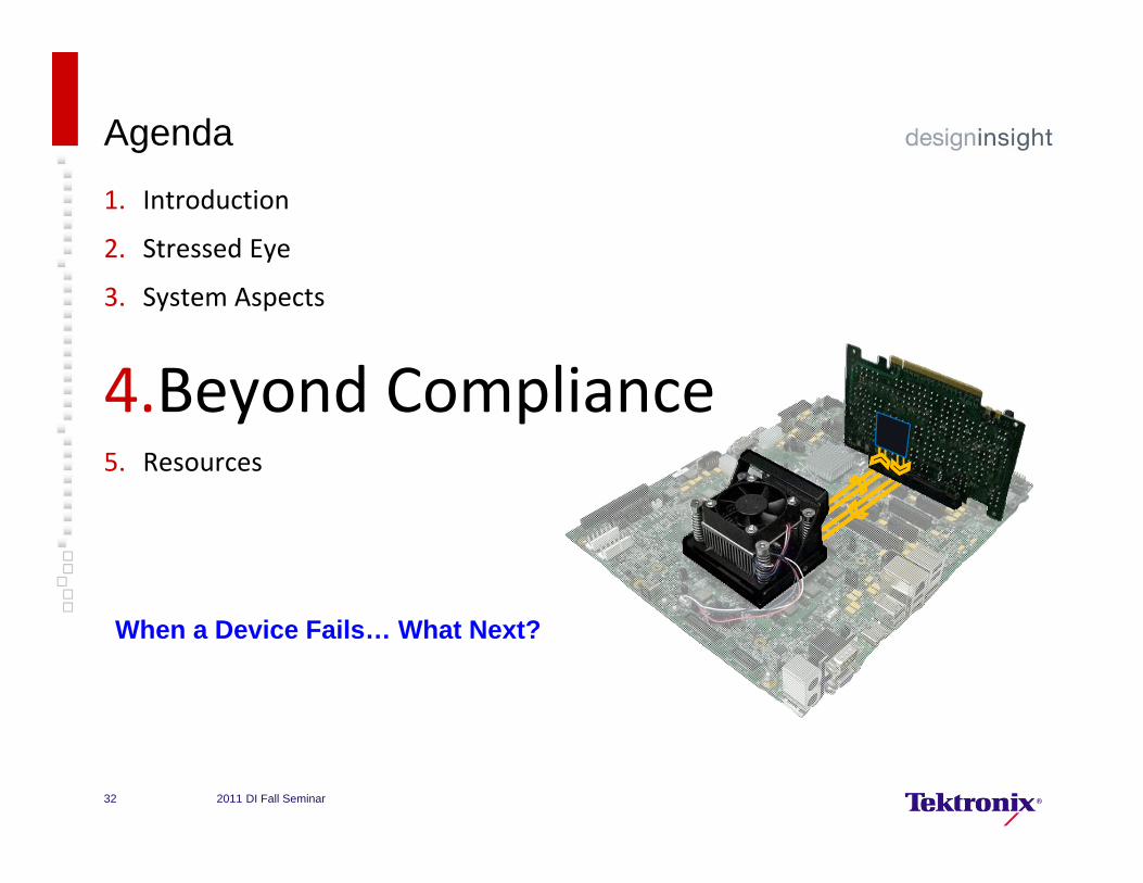
Agenda
1. Introduction
2. Stressed Eye
3. System Aspects
4.Beyond Compliance 5. Resources
When a Device Fails… What Next?
2011 DI Fall Seminar32
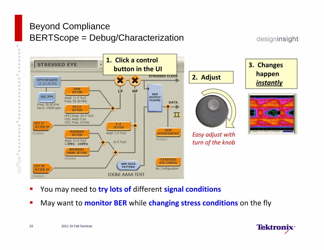
Beyond ComplianceBERTScope = Debug/Characterization
You may need to try lots of different signal conditions
May want to monitor BER while changing stress conditions on the fly
Easy adjust with turn of the knob
1. Click a control button in the UI
2. Adjust
3. Changes happen instantly
2011 DI Fall Seminar33
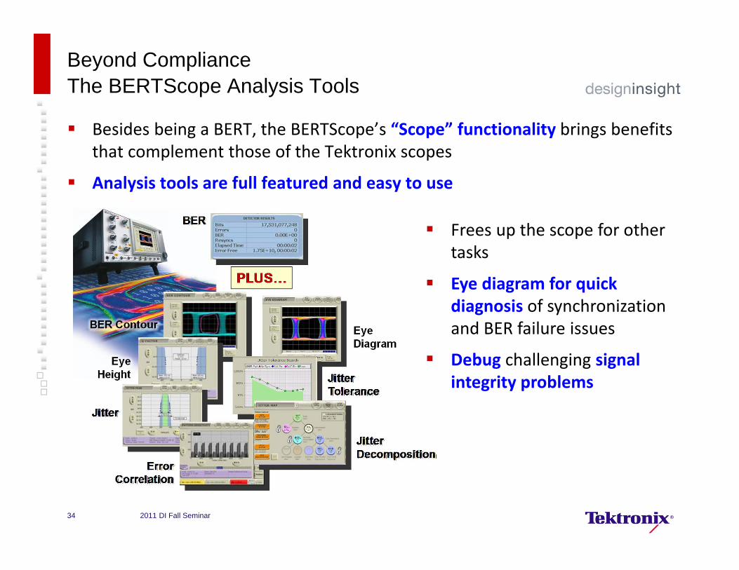
Beyond Compliance The BERTScope Analysis Tools
Besides being a BERT, the BERTScope’s “Scope” functionality brings benefits that complement those of the Tektronix scopes
Analysis tools are full featured and easy to use
Frees up the scope for other tasks
Eye diagram for quick diagnosis of synchronization and BER failure issues
Debug challenging signal integrity problems
2011 DI Fall Seminar34

Agenda
1. Introduction
2. Stressed Eye
3. System Aspects
4. Beyond Compliance
5. Demonstration
6.Resources
2011 DI Fall Seminar35
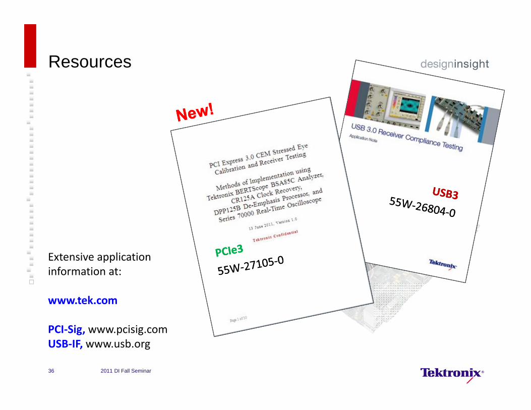
Resources
Extensive application information at:
www.tek.com
PCI‐Sig, www.pcisig.comUSB‐IF, www.usb.org
2011 DI Fall Seminar36
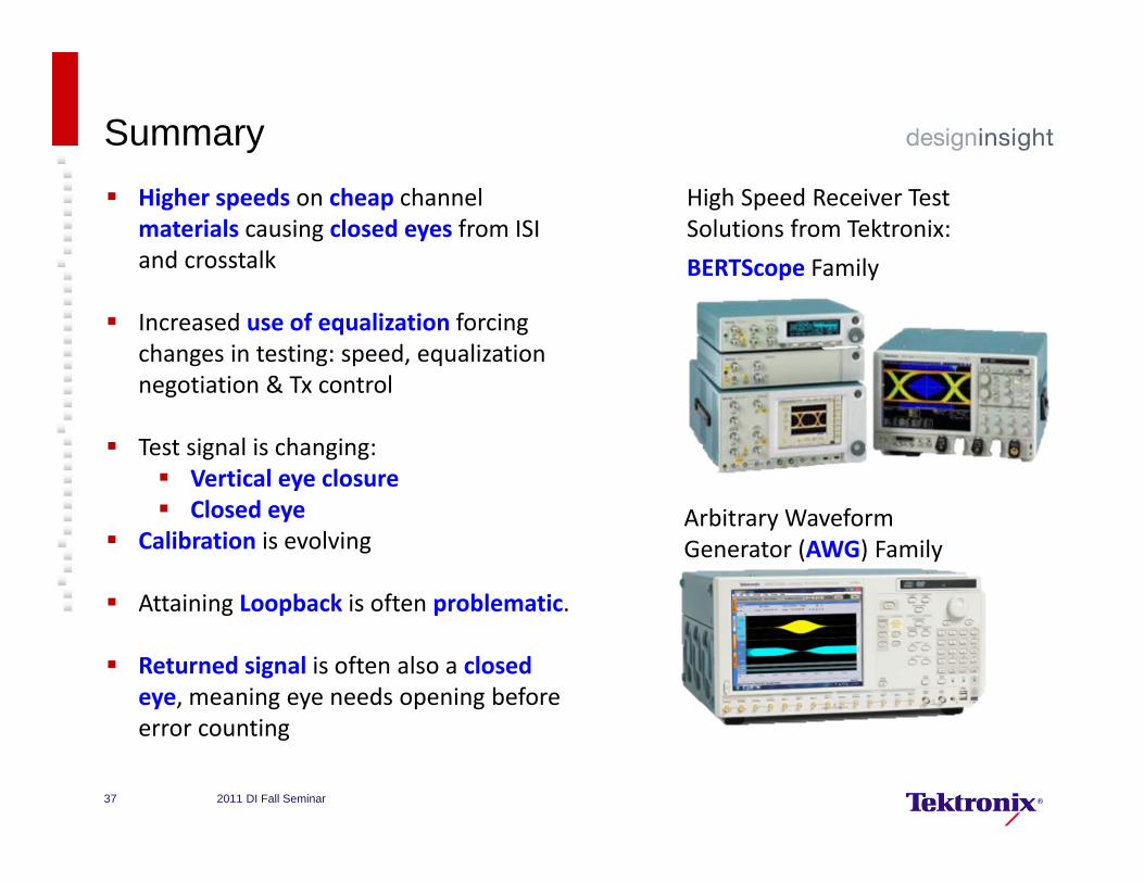
SummaryHigh Speed Receiver Test Solutions from Tektronix:BERTScope Family
Arbitrary Waveform Generator (AWG) Family
Higher speeds on cheap channel materials causing closed eyes from ISI and crosstalk
Increased use of equalization forcing changes in testing: speed, equalization negotiation & Tx control
Test signal is changing: Vertical eye closure Closed eye
Calibration is evolving
Attaining Loopback is often problematic.
Returned signal is often also a closed eye, meaning eye needs opening before error counting
2011 DI Fall Seminar37
.
Questions?Questions?
2011 DI Fall Seminar38

39 2011 DI Fall Seminar