
Realizing a Resonator Cooling scheme forUltra-Cold Fermi Gases
83
Transcript of Realizing a Resonator Cooling scheme forUltra-Cold Fermi Gases

Diploma thesisFlorian Wittkötter
Realizing a Resonator Cooling scheme forUltra-Cold Fermi Gases
Universität HamburgInstitut für Laserphysik
Arbeitsgruppe Quantenmaterie
Evaluators:Prof. Dr. Henning MoritzProf. Dr. Klaus Sengstock
Hamburg, 21th April 2011

Abstract
In the frame of this diploma thesis a vacuum chamber and a resonator for the ecientcooling of atomic gases in a new experiment was designed and tested.An essential part of the novel cooling scheme utilized is an optical dipole trap. In thisdipole trap the atoms will be captured and cooled to the quantum degenerate regime byforced evaporation. A large trap depth is necessary in order to transfer a large number ofatoms from the magneto-optical trap which is used for precooling into the dipole trap. Adeep dipole trap can be realized with moderate laser power using the power enhancementof a resonator. It is possible to load from a relatively large volume since the transfer iscarried out outside of the focus of the resonator mode at a large beam radius. A sub-sequent transport of the atoms to the focal region increases the density and thereby theeciency of the evaporation.The construction of the vacuum chamber and the resonator are strongly connected sincethe resonator is placed inside the vacuum chamber. The cavity losses are strongly re-duced inside the vacuum chamber which enables the large desired enhancement of thelaser power. The vacuum chamber and the resonator were designed as 3D-models andmanufactured by professional workshops. A laser system for the characterization of theresonator was built and a feedback loop with a bandwidth of approximately 40 kHzwas implemented. With this setup the nesse of the resonator was determined to beF = 4155± 453 which is equivalent to an enhancement by a factor of 1323± 144.

Contents
1 Introduction 3
2 Framework 5
2.1 Cold gases . . . . . . . . . . . . . . . . . . . . . . . . . . . . . . . . . . . . 52.1.1 Quantum statistics . . . . . . . . . . . . . . . . . . . . . . . . . . . 62.1.2 Laser cooling . . . . . . . . . . . . . . . . . . . . . . . . . . . . . . 72.1.3 Evaporative cooling . . . . . . . . . . . . . . . . . . . . . . . . . . 102.1.4 Dipole force . . . . . . . . . . . . . . . . . . . . . . . . . . . . . . . 122.1.5 Evaporation in dipole traps . . . . . . . . . . . . . . . . . . . . . . 14
2.2 A new cooling scheme . . . . . . . . . . . . . . . . . . . . . . . . . . . . . 152.2.1 Atom preparation cycle . . . . . . . . . . . . . . . . . . . . . . . . 152.2.2 Evaporation scheme . . . . . . . . . . . . . . . . . . . . . . . . . . 162.2.3 Experimental goals . . . . . . . . . . . . . . . . . . . . . . . . . . . 18
3 The vacuum system 20
3.1 The apparatus . . . . . . . . . . . . . . . . . . . . . . . . . . . . . . . . . 203.2 The main vacuum chamber . . . . . . . . . . . . . . . . . . . . . . . . . . 223.3 Vacuum techniques . . . . . . . . . . . . . . . . . . . . . . . . . . . . . . . 23
3.3.1 Vacuum leaks . . . . . . . . . . . . . . . . . . . . . . . . . . . . . . 233.3.2 UHV anges . . . . . . . . . . . . . . . . . . . . . . . . . . . . . . 243.3.3 Outgassing . . . . . . . . . . . . . . . . . . . . . . . . . . . . . . . 253.3.4 Vacuum gauge . . . . . . . . . . . . . . . . . . . . . . . . . . . . . 253.3.5 Electrical feed-through . . . . . . . . . . . . . . . . . . . . . . . . . 26
3.4 Optical access . . . . . . . . . . . . . . . . . . . . . . . . . . . . . . . . . . 273.4.1 Beams in the main chamber . . . . . . . . . . . . . . . . . . . . . . 273.4.2 Viewports for the main chamber . . . . . . . . . . . . . . . . . . . 29
3.5 Mechanical boundary conditions . . . . . . . . . . . . . . . . . . . . . . . 303.5.1 Magnetic elds in the main chamber . . . . . . . . . . . . . . . . . 313.5.2 Chamber and resonator mounting . . . . . . . . . . . . . . . . . . . 333.5.3 Vacuum pumps and materials . . . . . . . . . . . . . . . . . . . . . 33
4 The cooling resonator 36
4.1 Resonator theory . . . . . . . . . . . . . . . . . . . . . . . . . . . . . . . . 364.1.1 Basic characteristics . . . . . . . . . . . . . . . . . . . . . . . . . . 364.1.2 Transverse modes . . . . . . . . . . . . . . . . . . . . . . . . . . . . 394.1.3 Geometric stability . . . . . . . . . . . . . . . . . . . . . . . . . . . 404.1.4 Frequency stabilization . . . . . . . . . . . . . . . . . . . . . . . . . 42
1
4.2 Design considerations . . . . . . . . . . . . . . . . . . . . . . . . . . . . . . 454.3 The design process . . . . . . . . . . . . . . . . . . . . . . . . . . . . . . . 46
4.3.1 Finding the optimal parameters . . . . . . . . . . . . . . . . . . . . 474.3.2 Mechanical realization . . . . . . . . . . . . . . . . . . . . . . . . . 494.3.3 The piezoelectric actuator . . . . . . . . . . . . . . . . . . . . . . . 53
5 Testing the resonator 55
5.1 Optical setup . . . . . . . . . . . . . . . . . . . . . . . . . . . . . . . . . . 555.1.1 Layout of the optical setup . . . . . . . . . . . . . . . . . . . . . . 555.1.2 The laser source . . . . . . . . . . . . . . . . . . . . . . . . . . . . 575.1.3 Electro-optical modulators . . . . . . . . . . . . . . . . . . . . . . . 575.1.4 Acousto-optical modulators . . . . . . . . . . . . . . . . . . . . . . 585.1.5 The test resonator . . . . . . . . . . . . . . . . . . . . . . . . . . . 60
5.2 Electronic setup . . . . . . . . . . . . . . . . . . . . . . . . . . . . . . . . . 615.2.1 Overview of the electronic setup . . . . . . . . . . . . . . . . . . . 625.2.2 Controller . . . . . . . . . . . . . . . . . . . . . . . . . . . . . . . . 635.2.3 The lock-box . . . . . . . . . . . . . . . . . . . . . . . . . . . . . . 645.2.4 Photodiodes . . . . . . . . . . . . . . . . . . . . . . . . . . . . . . . 64
5.3 Characterization of the resonator and the feedback loop . . . . . . . . . . 655.3.1 Characteristics of the test resonator . . . . . . . . . . . . . . . . . 665.3.2 Speed of the feedback loop . . . . . . . . . . . . . . . . . . . . . . . 675.3.3 Finesse of the resonator . . . . . . . . . . . . . . . . . . . . . . . . 69
6 Conclusion & outlook 73
7 Appendix 75
7.1 Feshbach resonances . . . . . . . . . . . . . . . . . . . . . . . . . . . . . . 757.2 The glass cell . . . . . . . . . . . . . . . . . . . . . . . . . . . . . . . . . . 77
8 Bibliography 78
9 Acknowledgement 81
2

1 Introduction
Solid state physics is a driving force for technological progress since it trigger the devel-opment of new materials with unconventional mechanical, electrical, optical, and ther-modynamical properties. Understanding the basic principles underlying the intriguingproperties of some materials, however, is very challenging because many of the interestingfeatures arise from complex quantum many-body interactions. Often even the simplestapproximative models describing such intriguing phenomena as high temperature super-conductivity are not solvable in full detail with todays computational methods [20].The experimental realization of Bose-Einstein condensation [2] and Fermi degeneracy [7]in dilute gases of neutral atoms, however, led to a novel approach to this research eld.The experimental techniques developed to tune the interaction by Feshbach resonances [6]and to realize arbitrary potentials with the dipole force [10] allow for realization and pre-cise control of many parameters of general model Hamiltonians [9]. These quantumsimulations may shed new light on long standing questions of many elds of physics suchas solid state physics and in turn motivate new experiments.One of the prominent theories in this frame is the Hubbard model [16] describing elec-tronic properties in solid state systems. It can be simulated very accurately by meansof alkali atoms in optical lattices [18]. The current experimental challenges include theobservation of the quantum mechanical ground state of the Fermi-Hubbard Hamiltonian.For half lling this ground state is characterized by antiferromagnetic order and requiresvery low temperatures [5].In the presence of the pioneering progress in the eld of quantum optics during the pastyears and the arising fundamental questions a new apparatus optimized for the investi-gation of low dimensional systems is currently being built. The specic aim of the newexperiment is to maintain maximal exibility by means of atomic species employed aswell as possible potentials and excellent imaging capabilities. A prerequisite for reach-ing low temperatures in dilute gases is an ecient evaporation scheme with a fast cycletime and initial large atom numbers. For this reason a new all-optical cooling schemeconceived by T. Esslinger [32] is combined with a powerful microscope setup and a glasscell enabling excellent optical access.A common solution for trapping potentials for evaporative cooling are magnetic trapssince they oer large volumes and large trap depth. For fermions, however, magnetictraps have the drawback that the trapping potential depends on the spin state whichleads to a partially polarized gas. For identical fermions the collisions die out at lowtemperatures leading to a strong suppression of the thermalisation rate and hence of theevaporation eciency in magnetic traps. Furthermore, spin mixtures in magnetic trapstypically experience strong losses.Optical traps which are based on the dipole force oer a spin independent potential.
3

Yet a large volume and a high trap depth is necessary in order to guarantee an ecientloading of the evaporation trap from the previous magneto-optical trap. To simultane-ous reach a high trapping volume and depth as well as high thermalisation rates withthe optical dipole force is a challenging task. A resonator can be used to enhance theavailable laser power but for fast thermalisation high frequencies and thus tight focusingis necessary which is contrary to a large volume.In this diploma thesis the design of a ring resonator for a dipole trap enabling both, ahigh transfer volume and fast thermalisation is presented. The idea of the new evapo-ration scheme is to load the dipole trap from the MOT outside of the resonator focusin a standing wave conguration which is reached by coupling two counter-propagatingbeams into the resonator. After the loading process the frequencies of both beams aredetuned such that the interference pattern moves and the atoms are transported to thefocal region. Once the atoms are in the focus one of the beams is ramped down andevaporation is performed by lowering the power in the remaining beam. To enable highenhancement and thus a deep trap the resonator is placed inside the vacuum. Thereforethe design of the main vacuum chamber and the resonator is strongly connected andconsequently the design of the main vacuum chamber is also part of this diploma thesis.Finally a setup for the characterization of the resonator was built.In the rst chapter an introduction to general aspects of the manipulation of ultra-coldatoms and an overview of the atom preparation cycle is given. The second and thirdchapters address the design process of the vacuum chamber and the cooling resonatorrespectively. A summary of the optical and electronic setup required for operation of thecooling resonator is given in chapter four. Reports on rst characterizing measurementsare also included in the last chapter.
4

2 Framework
To observe quantum phenomena in a dilute gas of neutral atoms very low temperatures onthe order of 100 nK are necessary. To reach these low temperatures is a very challengingtask. In this experiment a new, advanced cooling scheme is set up in order to maintainmaximal exibility concerning the atomic species employed and with the intention toreach larger atom numbers and shorter cycle times than in previous experiments. By us-ing a ring resonator to create a dipole trap for the nal evaporative cooling it is possibleto enhance the loading eciency from the magneto-optical trap employed for precoolingas well as the evaporation speed with an all-optical and thus species-independent coolingprocedure (2.2). To further enhance the evaporation eciency Feshbach resonances (ap-pendix 7.1) will be employed which enable the control of the interaction strength betweenneutral atoms by a magnetic eld.Although the focus of this thesis lies at the design and testing of the vacuum chamberand the cooling resonator, a very brief introduction to techniques which generally enablethe cooling and trapping of neutral atoms is given (2.1). A detailed discussion of thesetechniques can be found in [22].
2.1 Cold gases
Nowadays many elements (mostly alkali metals) can routinely be cooled down to a fewhundred Microkelvin by laser cooling techniques (2.1.2). However, for the nal coolingstep all quantum gas experiments rely on evaporative cooling (2.1.3 and 2.1.5). Evap-orative cooling is based on the idea to remove the hottest atoms from a conservativetrap while the remaining atoms thermalize leading to a lower temperature. The trappingpotential determines the initial atom number and temperature as well as the thermali-sation rate thus making the choice of a suitable trap crucial. Apart from magnetic trapsoptical traps became a key technology for the investigation of ultra-cold gases becausethey allow trapping of all spin states in contrast to magnetic traps. Moreover they makea variety of dierent potentials from almost homogeneous bath tubs to dierent opticallattices possible.In this thesis a resonator for a new optical evaporation trap is realized which simultane-ously allows for a large and deep loading volume and fast thermalisation. Like all opticaltraps it is based on the optical dipole force which is the subject of section 2.1.4. Firstthe dierent behavior of bosons and fermions at low temperatures is discussed (2.1.1).
5

Figure 2.1 Schematic representation of bosons (left) and fermions (right) atT = 0K in two dierent spin states (red and blue). While bosons accumulatein the lowest state of a trapping potential fermions stack up to the Fermienergy.
2.1.1 Quantum statistics
The properties of an ideal gas (i.e. without interactions) under ambient pressure andtemperature can be derived completely from the Maxwell-Boltzmann distribution anddo not depend on the fermionic or bosonic nature of its constituents (classical limit).However, when the phase space density ρ1 approaches unity the wave functions of indi-vidual atoms start overlapping and the gas must be described using quantum mechanics.The occupation probability p of a quantum mechanical state i with energy εi is given bythe Fermi-Dirac (+1) and Bose-Einstein (−1) statistics respectively:
〈p(εi)〉 =1
eβ(εi−µ) ± 1(2.1)
where µ denotes the chemical potential and β := (kBT )−1 with Boltzman's constantkB = 1.38 · 10−23 JK−1. In the case of a trapped gas the energies εi are determined bythe trapping potential.For both distributions a temperature corresponding to a phase space density of approx-imately unity can be derived. Systems with a temperature below this crossover tem-perature are often referred as to be in a quantum degenerate state. To study quantummechanical eects, such as superuidity, in dilute vapors of neutral atoms the corre-sponding crossover temperatures in the Nanokelvin scale have to be reached.For a bosonic gas in an anisotropic harmonic trap2 the critical temperature Tc is deter-mined by the trap frequencies ωj and the number of atoms in the trap N :
Tc ∝ (ωxωyωzN)1/3 (2.2)
1ρ = nΛ3 with the number density n and the de Broglie wavelength Λ.2The trapping potential is given by: U(x, y, z) = 1
2m(ω2
xx2 +ω2
yy2 +ω2
zz2), where m is the mass of the
atom.
6

For temperatures below Tc the number of accessible exited states becomes less than thetotal number of atoms in the trap which leads to a macroscopic occupation of the singleparticle ground state (Bose-Einstein condensation). The investigation of this degeneratesystem is especially instructive since it makes a quantum mechanical single particle statemacroscopically observable.For fermionic atoms condensation is impossible because of the Pauli principle which statesthat two identical fermions can not occupy the same quantum mechanical state. Thisimplies that at T = 0 all states up to the so called Fermi energy are occupied exactlyonce and all others are empty. The corresponding Fermi temperature (TF ) is given by:
TF =EFkB∝ (ωxωyωzNi)
1/3 (2.3)
where again a harmonic trap is assumed and Ni denotes the number of atoms in a certaininternal state.The above discussion is only valid in thermal equilibrium and does not account for theeects of interactions at all. Yet interacting gases feature the exciting physics. Forexample, a gas of weak attractive interacting fermions at very low temperatures becomesuperuid similar to electrons in bulk materials. The dierence between bulk materialsand dilute gases is the excellent controllability of the potential3 and the interactionstrength for dilute gases hence making the study of these systems very instructive. Adescription of interaction phenomena and dynamics is beyond the scope of this thesisbut can be found in various text books and reviews such as [27] and [19].
2.1.2 Laser cooling
Two dierent light forces on atoms have to be distinguished, the conservative dipole forceand the scattering force. Here the scattering force is introduced in order to gain rstinsights into laser cooling. A more detailed discussion can be found in [22].The scattering force or radiation pressure relies on absorption and spontaneous emissionof photons. When a beam of near-resonant light is directed shone at a two-level atomthe latter will constantly absorb and reemit photons. Each absorbed photon gives rise toa recoil of momentum hk in the beam direction. The momentum transfer connected tothe spontaneous emission, however, averages to zero over time since it is isotropic. Theresulting force is velocity dependent and thus dissipative because of the Doppler shiftseen by a moving atom. More precisely, because of the Doppler shift the frequenciesof absorbed and emitted photons dier by ∆ which denotes the detuning of the laserfrequency with respect to the atomic transition frequency. Therefore every absorption-emission cycle gives rise to an energy exchange between the light eld and the atom ofh∆. For red detuning (∆ < 0) this exchange means a loss of energy from the system.Due to the Doppler eect an atom with a velocity component towards a red detuned lightbeam will more likely absorb photons from this beam than from a beam with the samefrequency as the rst beam but traveling in the opposite direction. Due to this preferred3Please note that inhomogeneities inevitably introduced by a realistic trapping potential in experimentsalso provides drawbacks.
7

Figure 2.2 A beam of light imposes a dissipative force on an atom due tothe momentum transfer from directed absorption and isotropic spontaneousemission (top). Six orthogonal, red detuned laser beams can be used to coolan atomic sample since atoms most likely absorb photons from a counter-propagating laser due to the Doppler eect (bottom). Please note that atomsare not trapped in an optical molasses
absorbtion of counter-propagating red detuned photons an atomic sample can be cooledin three dimensions by three pairs of counter-propagating laser beams (see gure 2.2).The temperature in such optical molasses is limited due to the random walk the atomsperform in momentum space caused by the arbitrary direction of spontaneous emission.The corresponding Doppler temperature can be derived from an equilibrium conditionbetween heating and cooling rate and is given by:
TD =hΓ
2kB(2.4)
where Γ is the linewidth of the atomic transition. For typical parameters this tempera-ture is of the order of some hundred Microkelvin and thus far above typical degeneracytemperatures (Tc and TF respectively) of a few hundred Nanokelvin.
Cooling with the scattering force
The atomic vapor for quantum gas experiments is produced by heating a small piece of
8

Figure 2.3 The hyperne states of an atom with total angular momentumF = 0 in the ground state and F = 1 in the excited state will split due to theZeeman Eect as depicted on the right when a magnetic eld gradient withB = 0 in the center is applied. Appropriate polarized red detuned (by ∆)counter-propagating laser beams (frequency ω) can be used to apply a spatialdependent force since o center atoms will come in resonance with a beampushing them to the center. An experimental setup to trap and cool atomsdue to the scattering force in all three dimensions is schematically shown onthe left (the black arrows indicates magnetic coils) .
the desired element which leads to the vapor due to increased vapor pressure. Coolingdown this vapor is one of the most challenging tasks when investigating phenomena inthe quantum degenerate regime. The cooling strategy strongly depends on the atomicspecies employed. Two very widespread techniques for the rst cooling step are the two-dimensional magneto-optical trap and the Zeeman slower.A magneto-optical trap (MOT) combines pairs of counter propagating, polarized laserbeams with a magnetic eld gradient such that the scattering force becomes space de-pendent. For atoms with an appropriate internal structure this can be used to cool andcollect the atomic gas at a specic position (see gure 2.3). Since the cooling in a MOTrelies on the scattering force the lowest achievable temperature is given by TD.By using the MOT principle for two dimensions in a volume with relatively high pressure,slow atoms from the background gas can be captured and cooled in these dimensions.Along the third dimension a pushing beam can be applied producing a dense beam ofrelatively slow atoms leaving the 2D-MOT region.For the Zeeman slower technique the atoms are heated in an oven where a small apertureallows for directional emission. A laser beam counter-propagating to the atomic beamgives rise to the scattering force which slows the atoms. To compensate for the changein the Doppler shift when the atoms slow down it is necessary to tune either the laserwavelength or the atomic transition frequency. A Zeeman slower achieves this compen-
9

Figure 2.4 The magnetic eld of the Zeeman slower used in this exper-iment on the axis (bottom) and a schematic representation of the Zeemanslower (middle) as well as of the velocity distribution at dierent points (top).The MOT eld is indicated in red. A smooth gradient of the total eld is fa-vorable to minimize unwanted diverging of the atomic beam thus making goodmatching between MOT and Zeeman slower eld necessary (elds calculatedby K. Morgener).
sation by a magnetic eld gradient and the associated Zeeman eect tuning the atomictransition frequency (see gure 2.4).Both methods prepare the atoms in a directed beam which may point at a three dimen-sional MOT. Here the atoms can be recaptured and cooled to the Doppler limit. Althoughthere are some very sophisticated schemes how to reach deeper temperatures with lasercooling it is impossible to achieve phase space densities of order unity. Therefore allquantum gas experiments use evaporative cooling as the nal cooling step.
2.1.3 Evaporative cooling
Evaporative cooling relies on the idea of removing the hottest atoms from a thermalensemble, by lowering the trapping potential for instance, leading to a reduced temper-ature after thermalisation. The achievable temperature depends critically on the trapemployed.The trap determines the initial atom number and temperature by the trapping volumeand depth respectively. A large initial atom number is important since more removedatoms lead to a lower temperature and a large degenerate cloud is desirable. Usuallyevaporation is performed after precooling in a MOT. Typically a large and deep trappingpotential is necessary in order to guarantee an ecient transfer of the atoms from theMOT.
10

Additionally the trapping potential determines the thermalisation rate, which is crucialfor an ecient evaporation since it determines the speed at which atoms can be removedpreserving thermal equilibrium. For example high densities4 and trap frequencies lead tohigh scattering rates and thereby to a fast thermalisation. High trap frequencies in turnare equivalent to a tight connement.The thermalisation is mediated by elastic two body scattering making the correspondingcross section decisive for ecient evaporation. For a radial symmetric scattering potentialsuch as atomic potentials it is convenient to expand the two-body scattering amplitude interms of spherical harmonics [31]. For high angular momentum the scattering potentialis modied by the centrifugal barrier such that for scattering with low energies only therst order term contributes to the scattering amplitude and cross section. This s-wavescattering cross section σ0 converges to a nite value in the limit of low temperatures(k → 0) given by:
σ0 = 4πa2 (2.5)
where the scattering length a is dened by this equation. The scattering length can betuned by a so-called Feshbach resonance modifying the interaction strength and therebythe thermalisation rate (appendix 7.1). To address a Feshbach resonance in an atomicsample a homogeneous, typically rather large, magnetic eld must be applied.In an intuitive picture s-wave scattering can be described as contact interaction. ThePauli exclusion principle, however, states that two identical fermions can not be simul-taneous at the same place. Therefore the thermalisation rate is strongly suppressed in apolarized gas of fermionic atoms. To avoid this so-called Pauli blocking it is favorable totrap a gas of fermions in a potential that is independent of the spin state for evaporativecooling.A common trap for cold atoms is the magnetic trap. It oers a large volume with ad-equate depth. The force in such a trap arises from the Zeeman eect which shifts theenergy of an atomic state according to:
∆εi = µBgimFiB (2.6)
where mFi is the projection of the total angular momentum Fi on the magnetic elddirection, gi is called the Lande g-factor and µB is the Bohr magneton. From thisformula it can be seen that only atoms with mFigi < 0 can be captured in a localmagnetic minimum5. It can also be seen that the potentials for dierent mF are notthe same. For spin mixtures6 this leads to spatial separation of the dierent states andsuch to a partially polarized gas. This causes serious problems for fermionic atoms asdiscussed above. Additionally magnetic traps are typically not compatible with the useof a Feshbach resonance. An alternative to magnetic traps is the optical trap which relyon the dipole force.
4Please note that a high density also lead to increased losses due to three body collisions.5Magnetic maxima are not possible in free space as can be seen from Maxwell's equations.6A gas of atoms in dierent spin states.
11
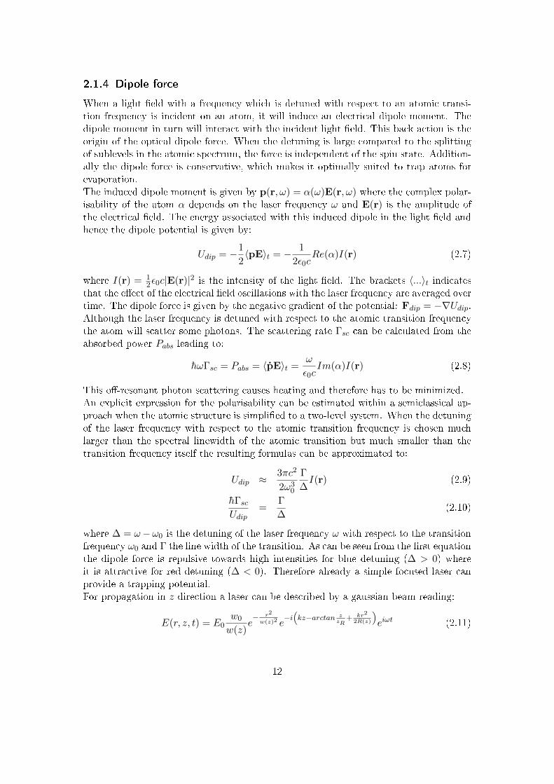
2.1.4 Dipole force
When a light eld with a frequency which is detuned with respect to an atomic transi-tion frequency is incident on an atom, it will induce an electrical dipole moment. Thedipole moment in turn will interact with the incident light eld. This back action is theorigin of the optical dipole force. When the detuning is large compared to the splittingof sublevels in the atomic spectrum, the force is independent of the spin state. Addition-ally the dipole force is conservative, which makes it optimally suited to trap atoms forevaporation.The induced dipole moment is given by p(r, ω) = α(ω)E(r, ω) where the complex polar-isability of the atom α depends on the laser frequency ω and E(r) is the amplitude ofthe electrical eld. The energy associated with this induced dipole in the light eld andhence the dipole potential is given by:
Udip = −1
2〈pE〉t = − 1
2ε0cRe(α)I(r) (2.7)
where I(r) = 12ε0c|E(r)|2 is the intensity of the light eld. The brackets 〈...〉t indicates
that the eect of the electrical eld oscillations with the laser frequency are averaged overtime. The dipole force is given by the negative gradient of the potential: Fdip = −∇Udip.Although the laser frequency is detuned with respect to the atomic transition frequencythe atom will scatter some photons. The scattering rate Γsc can be calculated from theabsorbed power Pabs leading to:
hωΓsc = Pabs = 〈pE〉t =ω
ε0cIm(α)I(r) (2.8)
This o-resonant photon scattering causes heating and therefore has to be minimized.An explicit expression for the polarisability can be estimated within a semiclassical ap-proach when the atomic structure is simplied to a two-level system. When the detuningof the laser frequency with respect to the atomic transition frequency is chosen muchlarger than the spectral linewidth of the atomic transition but much smaller than thetransition frequency itself the resulting formulas can be approximated to:
Udip ≈3πc2
2ω30
Γ
∆I(r) (2.9)
hΓscUdip
=Γ
∆(2.10)
where ∆ = ω−ω0 is the detuning of the laser frequency ω with respect to the transitionfrequency ω0 and Γ the line width of the transition. As can be seen from the rst equationthe dipole force is repulsive towards high intensities for blue detuning (∆ > 0) whereit is attractive for red detuning (∆ < 0). Therefore already a simple focused laser canprovide a trapping potential.For propagation in z direction a laser can be described by a gaussian beam reading:
E(r, z, t) = E0w0
w(z)e− r2
w(z)2 e−i
(kz−arctan z
zR+ kr2
2R(z)
)eiωt (2.11)
12

Figure 2.5 Schematic representation of a focussed Gaussian beam. For adescription of the indicated quantities see text.
where r2 = x2 + y2. As shown in gure 2.5 the beam radius w(z)7 evolves in z directionaccording to:
w(z) = w0
√1 +
(z
zR
)2
(2.12)
with the beam waist w0 and the Rayleigh range zR =πw2
0λ which is a measure for the
intensity variation in z direction8. R(z) indicates the radius of curvature of the wavefrontwhich has a minimum at z = zR and diverges for z → 0,±∞:
R(z) = z
(1 +
(zRz
)2)
(2.13)
Alternatively to those quantities the gaussian beam can also be described by a singleparameter:
1
q(z)=
1
R(z)− i λ
πω(z)2(2.14)
For the sake of completeness the intensity distribution can be calculated with the aid ofthe total beam power P =
∫∞0 2πI(r, 0)rdr = π
2w20I0 and is given by:
I(r, z) =2P
πw(z)2e−2 r2
w(z)2 (2.15)
The focused Gaussian beam with red detuned light is the simplest dipole trap but ofcourse other potentials are possible. For example interfering laser beams can provideoptical lattices in all dimensions and even more complicated potentials are possible bycombining attractive and repulsive traps.
7The value of r where the intensity dropped to 1e2
of it's value for r = 0.8I(0, zR) = 1
2I(0, 0)
13

For a specic application and atomic species the choice of an appropriate wavelengthand laser power is crucial to generate the desired potential. Nowadays many isotopesand even ions of dierent elements are routinely trapped and manipulated by the dipoleforce. It should be pointed out again that the dipole force is not dissipative and hencethe atoms will oscillate for ever in a dipole trap when no additional cooling mechanismis present.
2.1.5 Evaporation in dipole traps
Dipole traps are conservative and independent of the atomic spin state and thus optimallysuited to trap an atomic cloud for evaporative cooling. The evaporation process indipole traps is initiated by lowering the laser power. For an ecient evaporation fastthermalisation and ecient transfer from the previous cooling stage is essential.The thermalisation rate and hence the eciency of evaporative cooling is determined bythe density in the trap and the trap frequencies. For a dipole trap formed by a symmetricgaussian beam (ωx = ωy =: ωr) the trap frequencies in the radial (ωr) and longitudinal(ωz) direction are given by:
ωr =
√4U0
mw2(2.16)
ωz =
√4U0
mz2R
(2.17)
respectively. Here m denotes the mass of the atoms and U0 is the potential depth in thecenter of the trap which can be calculated with formulas 2.9 and 2.15. To reach highthermalisation rates and hence an ecient evaporation high trap frequencies are crucial.It can be seen from equation 2.17 that a high trap frequency in longitudinal direction isequivalent to thigh focussing of the laser. For an ecient transfer from a MOT, however,a rather large volume is required.Another drawback for dipole traps concerning evaporative cooling is the high intensityrequired to trap atoms. For typical parameters already laser powers on the order of somehundred Watts are necessary, even for a rather small overlap between the MOT anddipole trap. Especially for far o-resonante dipole traps high laser powers are necessary.Far detuned dipole traps are favorable in order to reach lower temperatures since photonscattering is reduced.A resonator can be used to enhance the trap depth for a given laser power. In additiona tight longitudinal connement is naturally provided by the interference pattern of thestanding wave in a two-mirror resonator. Unfortunately it turns out that the thermali-sation rate and thereby the cooling eciency in the resulting two-dimensional systems issuppressed by some mechanism not nally identied9.A ring resonator in contrast needs tight focusing in order to provide sucient longitu-dinal connement since the resonating mode (TEM00) can be described by a Gaussian9This phenomenon has not yet been systematically studied but has been observed in experiments inInnsbruck [23] as well as in Zürich [40] (personal discussion with H. Moritz).
14

beam. This tight focussing, however, leads to a small volume and therefore to a lowtransfere eciency.Simply loading the atoms from the MOT into a traveling wave resonator outside of thefocal region is not a good solution either. Because of the conservative nature of thedipole force the atoms will start strong oscillations where heating is the only dampingmechanism.
2.2 A new cooling scheme
For the observation of such exiting phenomena as anti-ferromagnetic order extremely lowtemperatures on the order of TT−1
F ≈ 0.06 are necessary. To reach these temperatureswith a reasonable large atomic sample and dierent atomic species a novel, all-opticalcooling scheme will be implemented. The large vacuum chamber (chapter 3) required toaccomodate the involved resonator trap severlely reduce the optical access at the coolingposition. Therefore the atoms are loaded into a dipole trap and transported into a glasscell after evaporation.After a brief summary of the entire atom preparation cycle (2.2.1), the strategy forevaporative cooling will be discussed in detail (2.2.2). The chapter will conclude with ashort outline of the experimental goals (2.2.3).
2.2.1 Atom preparation cycle
To achieve ultra low temperatures and high atom numbers a sophisticated cooling schemeis necessary. The rst element to be investigated in this experiment is fermionic lithium(6Li) but later an upgrade to other atomic species (Na, K) should be enabled. This de-mand for a exible scheme with high eciency for fermionic atoms makes an all-opticalcooling favorable.Figure 2.6 schematically shows the atom preparation scheme utilized in this experiment.Lithium vapor is created in an oven at approximately 400C. The atoms are releasedfrom this oven as a directed beam pointing at the main vacuum chamber, slowed downby a Zeeman slower and recaptured in a magneto-optical trap. The Zeeman slower isdesigned so that it may also be used for sodium. Potassium in contrast will be capturedfrom background pressure by a 2D-MOT. However, all atomic species are recaptured inthe three dimensional MOT and cooled to the Doppler limit (gure 2.6a).The nal evaporation is performed in a far detuned optical dipole trap. Good perfor-mance for all atomic species is reached by the choice of an appropriate wavelength andsucient laser power. For this purpose a new scheme for a resonator dipole trap is im-plemented (section 2.2.2). The basic idea of this scheme is to load the atoms from theMOT into a large volume of a dipole trap. Once the atoms are inside the dipole trapthey are moved adiabatically to the resonator focus (gure 2.6b). Finally evaporation isperformed by lowering the laser power circulating in the resonator (gure 2.6c).The cooling will be performed in a large vacuum chamber which prevents optimal opti-cal access. Therefore the nal experiments are performed in a glass cell (appendix 7.2).The transport of the atoms from the cooling chamber to the glass cell is achieved via a
15

Figure 2.6 Schematic representation of the atom preparation cycle. TheMOT is loaded from an atomic beam (a) and the atomic sample is cooled toT ≈ TD. The atoms are then transferred into a far detuned optical dipole trapwich is formed by the interference pattern of two counterpropagating beams ina resonator and transported to the focus (b). In the focus evaporative coolingis performed (c). Finally the atoms are transported into the glass cell by asecond dipole trap (d).
dipole trap formed by a single focused laser beam (gure 2.6c). For this transport only arelatively low laser power is required since the atomic gas is already relatively cold. Thefocusing lens for the transport trap is mounted on an air-bearing translation stage suchthat the focus can be shifted from the focus of the dipole trap were the nal evaporationis performed into the glass cell were the experiments take place.
2.2.2 Evaporation scheme
For an ecient evaporation scheme a large and deep dipole trap is desirable. A resonatorcan be used to enhance the available laser power. Following the discussion in section2.1.5 neither a typical standing wave resonator nor a typical ring resonator provides adipole trap for an ecient evaporation scheme. An idea how to combine a large capturevolume with high thermalisation rates and overcome the drawbacks of conventional dipolecooling resonators was conceived by Tilman Esslinger and rst described in [32].The basic idea is as follows: First the atoms are loaded from a MOT into the large
16

Figure 2.7 Schematic representation of the single steps performed in theresonator dipole trap. From top to bottom: First the atoms are loaded fromthe MOT into the interference pattern of two counter propagating beams.By itroducing a frequency dierence the atoms are then transported to thefocal region where one beam is ramped down. Finally evaporative cooling isperformed by lowering the power in the remaining beam.
volume of a standing wave interference pattern. Then this atoms are moved inside theinterference pattern into a focus region such that no heating occurs (adiabatical). Finallythe trap is changed to a running wave conguration and the evaporation is performed(see gure 2.7).Exactly this scheme can be realized by coupling two counter-propagating beams into aring resonator providing a small focus. When the frequencies of both beams are identical,a standing wave pattern will emerge. The spacing of the individual interference maxima isgiven by half the wavelength of the utilized light. By choosing the loading position outsidethe resonator focus a rather large overlap between the resonator mode and the MOT canbe achieved. After the MOT light and magnetic coils are switched o the frequenciesof the two beams are slightly detuned and consequently the interference pattern startto move. The captured atoms can be transported in the moving interference pattern tothe focal region. Here the focus itself provides longitudinal connement and one of thebeams can be ramped down. The evaporation can now be performed in this running waveconguration by simply lowering the power in the remaining beam. Since the transportincreases the density of the atomic cloud the thermalisation rate will also be enhanced.
17

Figure 2.8 A homogeneous dipole potential for neutral atoms (bottom)can be generated by superimposing a red detuned (top) and a blue detuned(middle) laser beam.
Furthermore since no magnetic elds are required for trapping, the thermalisation ratecan be further enhanced by use of a Feshbach resonance. With this resonator evaporationscheme a powerful tool for ecient cooling of fermionic atoms is available.
2.2.3 Experimental goals
The last decade has seen extraordinary progress in the research eld of ultra-cold fermionicgases. A systematic review of this development was compiled by M. Inguscio, W. Ket-terle and C. Salomon [17]. Recently intriguing systems such as imbalanced spin mixtures,bose-fermi mixtures [11] [26], fermions in optical lattices, double wells with few atoms [1]and far from equilibrium situations in general [28] attract scientic attention. To po-tentially contribute to all of these topics the new experiment is designed with a exiblebut nevertheless very powerful cooling scheme and excellent optical access to the atomiccloud. This optical access is guaranteed since the atoms are moved from the coolingposition into a at glass cell for the experiments.Imaging of the atoms is accomplished with a high resolution (≈ 600 nm) microscopeabove the glass cell. A second, identical microscope placed opposite to the rst oneallows for manipulations on the same length scale. Around the microscopes Feshbachcoils are placed to allow for tuning the interaction strength. Besides the superior opticalaccess enabled by a glass cell compared to a metal cell, a glass cell also allows for fastswitching of the magnetic elds since no eddy currents are present.Dipole traps are used to hold the atoms during the experiments. Here various potentialsare possible. To achieve very clean potentials an arrangement of two ring resonatorsplaced around the glass cell will be utilized. These resonators provide very ellipticalmodes and guarantee perfectly superimposed modes when dierent beams are coupledinto the resonators. For example a red and a blue detuned laser beam coupled in simulta-neously make the creation of very homogeneous potentials possible as depicted in gure2.8. In the vertical direction two blue detuned laser beams under a small angle will beused to create two dimensional systems. Because of the wide spacing between two sheetsin this geometry it is possible to only occupy one layer. Of course also systems in lowerdimensions are realizable by coupling counter propagating lasers into the resonators.
18

Figure 2.9 Schematic representation of fermions in two dierent spin states(blue and red) in an optical lattice. For low energies the properties of thesystem are determined by the tunneling between adjacent sites (J) and the onsite interaction (U). This state is described by the Hubbard model.
This setup enables the investigation of the properties of interacting fermions in two-dimensional optical lattices within the Hubbard model and beyond. The Hubbard modeldescribes interacting particles in the lowest band of a lattice potential. The physicalproperties of atoms in optical latices within the Hubbard model are determined by thetunneling matrix element between adjacent sites J and the on-site interaction energy U .The Fermi-Hubbard Hamiltonian for spin 1
2 particles in optical lattices reads:
H = U∑i
ni,↑ni,↓ − J∑i,j,σ
c†i,σ cj,σ +∑i,σ
εini,σ (2.18)
where the rst term describes the interaction energy and the second the kinetic energyin the system. The occupation number operator of site i is given by ni,σ = c†i,σ ci,σ where
c†i,σ and ci,σ denote the creation and annihilation operator of a particle with spin σ (↑ or↓) respectively. The last term takes into account the possible inhomogeneity within thelattice where εi denotes the site specic oset.Possible experiments in this context are to impose local excitations and observe thepropagation of the excitations through the lattice or to rapidly change the interactionstrength with respect to the tunneling rate (interaction quench) and investigate thethermalisation properties [8]. Obviously the planned setup also oers a wide range ofother opportunities.
19

3 The vacuum system
The lifetime of an ultra-cold atomic gas in a trap is limited by light scattering, threebody collisions and scattering with background atoms. While the rst two are inevitableassuming a given light eld and interaction strength, the latter only depends on thebackground pressure. Therefore every quantum gas experiment is performed under ultra-high vacuum (UHV) conditions. To achieve pressures as low as 10−11 mbar a sophisticatedvacuum system is necessary.In the frame of this diploma thesis the main vacuum chamber for the new experiment,where the cooling cycle takes place, was designed. The main constrains on the chambergeometry are dened by the desired optical access (3.4) and the coils for the high magneticeld which are necessary to address Feshbach resonances (3.5). Many general aspectsfor reaching the UHV have to be considered when planning a new vacuum system wherethe most important with respect to this work are introduced in (3.3). However, rst anoverview of the whole vacuum system (3.1) and the geometric boundary conditions onthe main chamber (3.2) are given.
3.1 The apparatus
Figure 3.1 shows a CAD drawing of the entire vacuum system with the arrangement forthe magnetic coils. In the following the main parts will be introduced.The cooling scheme discussed in 2.2.2 provides good performance for dierent atomic
Figure 3.1 A CAD-drawing of the vacuum system and the magnetic coils.One sees the oven, the Zeeman slower, the main vacuum chamber and thearrangement for the magnetic coils as well as the main vacuum pump.
20

Figure 3.2 The main chamber within the vacuum system, the design processis discussed in sections 3.4 and 3.5. The mounts which are designed to attachthe magnetic coils after the bake-out of the vacuum system is performed areindicated as well as the galss cell, the valve for the upgrade with a 2D-MOT andthe vacuum gauge and the titanium sublimation pump for the main chamber.
species, where lithium is the rst element which will be investigated but a later upgradefor sodium and potassium is taken into account. The lithium vapor is created in an ovenand guided through a Zeeman slower into the main vacuum chamber. In this chamber thefurther cooling steps are performed. The Zeeman slower length and coil arrangement isoptimized for an ecient cooling of both, lithium and sodium as well as for good matchingwith the MOT eld. Therefore the apparatus can be upgraded for sodium by a simplemodication of the oven and a more costly adaption of the laser system. Potassium willbe produced in an additional 2D-MOT where at the moment only a valve1 is placed toenable this option.A magnetic rotary feed-through2 behind the oven allows for blocking the atomic beamwhen not needed. Since no mechanical wear will occur the beam can be blocked everyexperimental cycle. The advantage of this beam shutter is that the window oppositeto the oven is not continuously exposed to the lithium which would deposit on it andthus decrease the optical access or even destroy the viewport. Nevertheless it may benecessary to heat the window in order to get rid of the deposited material or even toreplace it by a new one. For this purpose a valve3 is placed behind the large ion pumpfor the main chamber. A second valve is provided to attach the primary vacuum pumps.Another valve4 can separate the oven from the remaining vacuum system in order tomake easy repair and upgrad possible.The Zeeman coil is not wrapped directly around the vacuum tube but on a larger tubewhich provides cooling by an inner water ow. The advantage of this separate mountingis that no heating which would decrease the vacuum through enhanced outgassing or
1All metal inline valve from MDC Vacuum.2Vacom: MagiDrive MD16.3VAT Vacuum Valves: All-Metal Gate Valve CF40 Inventory:QM-000194VAT Vacuum Valves: All-Metal Gate Valve CF16 Inventory:QM-00020.
21

Figure 3.3 Scaled summery of all parts determining the geometry of themain vacuum chamber. Shown are the magnetic coils and the resonator beams(purple, details in chapter 4) as well as the beams for the MOT (red), the Zee-man slower (yellow), the transport dipole trap (green), the 2D-MOT (orange)and for imaging (blue).
vibrations are imposed on the vacuum system. The magnetic coils for the MOT and theFeshbach eld at the main chamber as well as at the glass cell are also mounted withoutcontact to the vacuum system.A dierential pumping tube at the entrance to the Zeeman slower allows for a pressure atthe oven several orders of magnitude higher than inside the main chamber (approximately10−9 mbar at the oven and 10−11 mbar in the main chamber). The vacuum at the oven isprovided by a small ion pump5 and an additional titanium sublimation pump. A vacuumgauge6 constantly monitors the pressure at the oven. At the main chamber a larger ionpump and another titanium sublimation pump are employed and again a vacuum gaugeis used to monitor the pressure.Figure 3.2 again shows the entire vacuum system but now the magnetic coils are removed.Here the main vacuum chamber with the glass cell can clearly be seen. Some details onthe glass cell can be found in appendix 7.2 whereas the main chamber will be discussedin the following.
3.2 The main vacuum chamber
A goal of this diploma thesis was the design of the main vacuum chamber. The geometryof this chamber is determined by the coils for the magnetic elds for the MOT and foraddressing the Feshbach resonances as well as by the required optical access.
5A 15ls−1 nitrogen ion pump from Gamma Vacuum: 25S-DI-2V-SC-N-N Inventory: QM-00071.6A combined Pirani - Bayard - Alpert sensor from Pfeier Vacuum: PBR260, Inventory: QM-00036.
22

The same coils should be used for the Feshbach and the MOT eld7 but since the twocentral positions do not coincide additional pushing coils are required for the MOT eld.All of these coils are depicted in gure 3.3 together with the beams determining theoptical access necessary.The cooling scheme discussed in section 2.2.2 will be performed in the main vacuumchamber and requires an appropriate optical access. An atomic beam is either createdby a Zeeman slower (yellow) for lithium and sodium or a 2D-MOT (orange) for potas-sium. This atomic beam loads a MOT (red) where the atoms are cooled to the Dopplerlimit. Subsequently the atoms are transferred into the resonator dipole trap (purple),transported into the focus of the resonator mode and evaporatively cooled by loweringthe power circulating in the resonator. After evaporation the atoms must be transportedinto the glass cell. This is achieved by a second dipole trap (green) where the focus andthereby the atomic vapor can be moved. It is desirable to image (blue) the atomic cloudfrom dierent directions in order to gain full information about the three dimensionaldensity distribution.In addition to these optical accesses ports for some vacuum devices are necessary. Inthe main vacuum chamber a pressure below 10−11 mbar is essential. This pressure isprovided by a large ion pump and an additional titanium sublimation pump. The pres-sure is monitored by a vacuum gauge and an electrical feed-through is required for thefrequency stabilization of the cooling resonator.The mounting of the cooling resonator provides additional restraints on the chambergeometry. The design of both, the resonator and the chamber were performed in parallelbut in this thesis for clarity the resonator will be discussed separately in chapter 4 wherethe vacuum chamber will be treated as a given boundary condition. Before the designprocess of the vacuum chamber will be addressed in detail in sections 3.4 and 3.5 a shortintroduction to vacuum techniques is given now.
3.3 Vacuum techniques
When planning a chamber for experiments under UHV conditions many technical detailshave to be considered. In the following section the most important aspects with respectto this work will be outlined. In particular these are the aspect of vacuum leaks (3.3.1),the problem of outgassing (3.3.3) and appropriate UHV connections (3.3.2). For a morecomplete and detailed discussion of techniques for the generation of ultra-high vacuumthe reader is referred to [25]. This section is concluded by very short introductions ofvacuum gauges (3.3.4) and electrical feed-throughs (3.3.5).
3.3.1 Vacuum leaks
It is crucially important that no leaks connect the inner part of a vacuum chamber tothe environment. At the required pressures even smallest cracks will rapidly reduce thevacuum quality. Even when there are no real leaks the vacuum can suer from so called
7One only has to change from a Helmholtz to an anti-Helmholtz conguration.
23

Figure 3.4 Working principle of CF connections (taken from [30]). The twoanges (dark blue) provide edges which are ditching in the gasket (yellow) ofa soft metal (e.g. copper) when the two anges are tightly screwed together.
virtual leaks.Virtual leaks are small, nearly closed volumes within the chamber in which air is trappedwhich is released only over very long timescales so that ecient pumping is not possible.For example badly performed welding may lead to virtual leaks. In order to guaranteewelding without virtual leaks it is important to ensure good access to every weld whendesigning a vacuum chamber. Another possible source of virtual leaks are two surfacesdirectly contacted to each other. Since they will never be exactly at these contactscan trap air and should be avoided in the design process. Virtual leaks are especiallyannoying since they can not be found by leak testing. Leak testing is done by applyinghelium selectively to the point at the chamber where the leak is suspected while a specialsensor connected to the vacuum pumps measures the helium concentration in the gaspumped from the chamber.
3.3.2 UHV anges
The mounting of pumps, measuring gauges and viewports to a vacuum chamber in theUHV regime is another crucial point. The mounting in the UHV regime is accomplishedwith so called CF anges (con at R© connections). CF anges have an edge at bothsides and a gasket of some soft metal (e.g. copper) is placed in between the two knifeedges. Both parts are tightly screwed together and an all metal seal is realized (see gure3.4). When assembling CF connections it is important to evenly tighten the screws toguarantee a good seal.Dierent gaskets are used for special situations. For example lithium reacts chemicallywith copper and correspondingly might destroy copper gaskets when the gasket is exposedto too high concentrations of lithium. Nickel gaskets are used at the oven for this reason.Since viewports are quite sensitive to stress it is convenient to use annealed coppergaskets, which are softer but also more expensive, to attach viewports to the vacuum
24

system. A general drawback of CF-connections is that they are very massive and thusneed much space.
3.3.3 Outgassing
Every material shows outgassing, i.e. sublimation and desorption into the vacuum, whichleads to a decreasing vacuum quality and therefore has to be minimized. The choice ofmaterial is crucial for this aspect. Stainless steel shows low outgassing and a high me-chanical stability8 and is therefore the preferred material for vacuum chambers. Theresidual outgassing of mainly hydrogen [14] can be further suppressed by heating thechamber when evacuated (bake-out). Most gas from the surface and from inside the ma-terial will thereby be lost before the experiments start. Typical bake-outs are performedat a few hundred degrees Celsius for some days to weeks.The bake-out will be more ecient when the whole chamber is placed inside a vacuumand the temperature is on the order of 900 C (vacuum annealing). Yet vacuum annealingworks only for high-quality stainless steel (e.g. 316 grade) since for low quality stainlesssteel (e.g. 304 grade) the high temperatures may lead to inter crystalline corrosion. Intercrystalline corrosion causes smallest tears between the crystalline parts of the material(leaks) and therefore decrease the nal vacuum.In any case it is recommended to heat the chamber under atmosphere when assembled.Thereby long organic (grease) molecules are destroyed which may otherwise survive vac-uum bake-out and pumping.Of course also the inner chamber surface is important regarding the vacuum quality.There are some special surface treatments promising an improved vacuum. For exampleelectropolishing reduces the surface roughness and thereby suppresses outgassing. Bydepositing a non-evaporable getter9 on the chamber surface the surface even acts as ad-ditional sorption pump and once the getter material is saturated, it can be reactivatedby heating the chamber [24]. However, since appropriate pressures are typically reachedwithout any special surface treatment the inner surface of the main chamber in this ex-periment was only mechanically processed.
3.3.4 Vacuum gauge
For observation of pressures down to 10−11 mbar the most suitable gauges work withthe hot cathode principle. Here electrons from a heated lament ionize the residual gas,the ions are collected and the resulting current can be used to determine the pressure.The outcome of this measuring principle depends on the composition of the residual gasrequiring a calibration or at least a corrective factor. Since in this experiment the exactcomposition of the residual gas is not known an error in the absolute value of the vacuum
8In contrast to glass for example which shows extremely low outgassing but is mechanically much moresensitive.
9A getter is a material which binds atoms from the residual gas by means of a chemical reaction(chemisorption) [29].
25

Figure 3.5 A Bayard-Alpert vacuum measuring gauge mounted on a CF40vacuum ange (taken from [38]). The lament on the right side (held bythe springs) emits electrons when heated. The electrons are accelerated by aelectric eld generated by the coil and subsequently ionize the residual gas.The ions are collected by the center anode generating a current which is ameasure for the pressure.
measurements is inevitable.The most widespread hot cathode type is the Bayard-Alpert-sensor (gure 3.5). It pro-vides a measuring range from 10−2 mbar to 10−11 respectively 10−2 mbar to 10−9 mbardepending on the acceleration grid10. Only the extractor-principle can measure evenlower pressures (down to 10−13 mbar).
3.3.5 Electrical feed-through
The electrical feed-through for the piezoelectric tube voltage in this experiment is a twopin version11 which allows for high voltages with a compact design. A critical point forsuch feed-throughs is the isolation since it has to be UHV suitable and therefore mustshow low outgassing rates. Commonly ceramics are used for this purpose which have thedrawback of being sensitive to mechanical stress and therefore easily show leakages whennot handled with care.
10Here a Varian (Agilent Technologies): UHV-24P Ion Gauge with a XGS-600 Gauge Controller ischosen. Inventory: QM-00061 and QM-00062
11Vacom: CF16-HV6-2-CE-SS13.
26

Figure 3.6 The main vacuum chamber with all the dierent rays passingthrough it. The MOT and the Zeeman slower are indicated in a, the resonatorrays and transport dipole trap in b and the 2D-MOT and imaging beams inc. All beams are shown in d.
3.4 Optical access
The shape of the main vacuum chamber is mainly determined by the desired opticalaccess. Beside appropriate anges at the main chamber for every beam (3.4.1) the choiceof corresponding viewports is also important. For example, a viewport with a very atsurface is needed for the transport dipole trap whereas for the anges near the glass cella low magnetic susceptibility is essentiell (3.4.2).
3.4.1 Beams in the main chamber
For the cooling scheme described in 2.2.1 and 2.2.2 many laser beams are used, requiringan appropriate optical access. An overview of all beams involved and the resultingchamber geometry can be seen in gure 3.6. In the following paragraphs the requirementsdening the position of every single beam are summarized. Additional drawings of theresulting chamber are given in gure 3.12.
MOT beams
To realize the MOT three pairs of counter-propagating, orthogonal beams with a diameterof approximately 30mm are used. Hence six viewports are necessary. One of the MOTaxes is xed by the position of the magnetic coils. Since the MOT is situated o-centerwith respect to the magnetic coils very large viewports (CF100) at the top and bottom
27

ange of the chamber are used in order to exploit the available space optimally and allowfor imaging in vertical direction. Because the MOT beam diameter was chosen to beapproximately 30mm the viewports for the remaining MOT beams are CF40 viewports.
Zeeman slower and pumping tube
The lithium and potassium atoms are produced in an oven and decelerated by a Zeemanslower. The Zeeman slower has to be directed towards the MOT position. It only needsa relative small tube and corresponding ange (CF25) but some space around the angeshould be kept free in order to place the Zeeman coils as close to the chamber as possible.This close mounting will lead to a good matching between the Zeeman eld and the MOTeld.The slowing laser will be guided through the ion pump which is located opposite to theZeeman slower. A special feature of this ion pump is that it provide an optical passagemaking this placement possible. The tube for the ion pump has to be rather large toenable high pumping rates. An inner diameter of 72mm was chosen which is slightlylarger than the inner chamber height. The pump itself oers a CF100 ange which iswhy a CF100 is also welded to the chamber tube. In addition the electric feed-throughfor the piezoelectric actuator, a vacuum gauge and a titanium sublimation pump will bemounted to this tube. The titanium sublimation pump works best when it can coat thewhole inner chamber surface, therefore a tilted mounting position is chosen.
Resonator beams
The resonator for the novel cooling scheme is placed inside the vacuum chamber. Toenable incoupling and power monitoring additional viewports are used. Their position isdetermined by the position of the resonator (chapter 4). For the incoupling viewport aCF40 ange was chosen because the large clear aperture enables both, incoupling throughone mirror and observation of the spot size, more precisely the beam divergence, throughanother mirror. For the power monitoring a CF16 ange is sucient. The CF16 angeas well as the CF40 ange are slightly tilted with respect to the horizontal plane becausethe corresponding beams will be tilted as well.
Transport dipole trap and glass cell
After evaporation the atoms are loaded into a second dipole trap and transported tothe glass cell. For the focused laser providing the dipole trap two viewports must beplaced such that the beam intersect the center of the Feshbach coils. For the size of theviewport the divergence of the transport beam and the distance to the nal position inthe glass cell is crucial. The beam waist of the dipole trap of approximately 20µm andthe distance between glass cell and viewport of approximately 500mm lead to a beamdiameter for which a CF40 ange is sucient. For the glass cell ange it is important thatnot too many other chamber parts are located close to it since the optics and magneticcoils around the glass cell will occupy a signicant amount of space.
28

2D-MOT beams
To load, cool and use potassium the option to attach a 2D-MOT is considered. Theatomic beam from this 2D-MOT must be directed towards the MOT position. It onlyneeds a very small entrance because it is located close to the chamber and correspondinglythe atomic beam will not have diverged much. Therefore a CF16 ange is sucient forthe 2D-MOT as well as for the viewport opposite for an optional slowing beam.Instead of the 2D-MOT only an all metal inline valve from MDC12 is installed at present.The valve is very compact compared to other better CF16 valves with larger opticalaccess. Of course it should be kept in mind that much more space will be needed for the2D-MOT vacuum chamber extension and the associated optics.
Imaging
Finally it is desirable to enable additional horizontal imaging at the position of theresonator focus perpendicular to the resonator beam. This turned out to be impossiblewithin the restriction given by all the anges discussed above. However, it was possibleto place two CF16 ports for imaging close to the optimal direction at a small angle withrespect to the horizontal direction.
3.4.2 Viewports for the main chamber
For the optical access appropriate viewports are necessary. For dierent beams and po-sitions at the main vacuum chamber special properties of the viewports are importantrequiering dierent viewports. In this experiment viewports from Larson Electronic Glassare chosen.The viewport for the transport dipole trap has to have a very good surface quality in or-der to avoid deformations of the beam during the transport which may lead to additionallosses. It is the glass to metal transition rather than the utilized glass itself which limitsthe surface quality. Usually the glass to metal brazing is performed at high temperatureswhich lead to stress and in turn decreases the surface atness. Therefore a special bond-ing with lead-silver alloy is employed for high quality viewports which can be processedat much lower temperatures. Unfortunately these viewports are much more expensiveand are not specied for operations at temperatures higher than 200 C13 yet the coatingis typically performed at 260 C. However, for the viewports used in this experiment thecoating was performed at 200 C wich results in a mechanically less stable coating andmay also decrease the transmission coecient.Since lithium is an aggressive material the viewport opposite to the Zeeman slower hasto withstand the corrosive eect. A sapphire viewport is appropriate and since a coatingwould be destroyed by the lithium it is not applied to this viewport. The viewports nearthe glass cell should show no residual magnetization in order to maintain precise controlover the magnetic elds for the experiments.Most viewports are anti-reection coated to minimize the losses when a laser beam shouldbe used inside the vacuum chamber. Since the possibility for magneto-optical traps and12MDC Vacuum Products: MIV-150-V modied with a CF16 ange at one side.13The melting point of lead-silver alloy is approximately 300 C.
29

Figure 3.7 The reection of the coated viewports for normal incidence asmeasured by Laseroptic Garbsen. As can be seen the losses are below 1 % forthe important range between 532nm and 1064nm.
imaging systems for dierent elements is considered a broadband anti-reection coatingis employed. The reection coecient as measured by the coating company is shown ingure 3.7, the losses are below 1% in the important range from 532 nm to 1064 nm.The inner side of all CF16 viewports is not coated since the relatively large metal angeswill partially block the coating beam thus making uniform results impossible. For CF16viewports this so called shadowing eect decreases the usable diameter of coated view-ports to approximately 5mm.
3.5 Mechanical boundary conditions
In addition to the optical access discussed in the previous section also some other outerboundary conditions apply for the design of the vacuum chamber. For example themagnetic coils used to realize the cooling scheme set constraints on the chamber geometry(3.5.1). Moreover, the problem of proper mounting of the vacuum chamber to the opticaltable and of the cooling resonator to the chamber has to be considered in this context(3.5.2). Finally the choice of material and appropriate vacuum pumps is crucial to reachthe UHV (3.5.3).
30
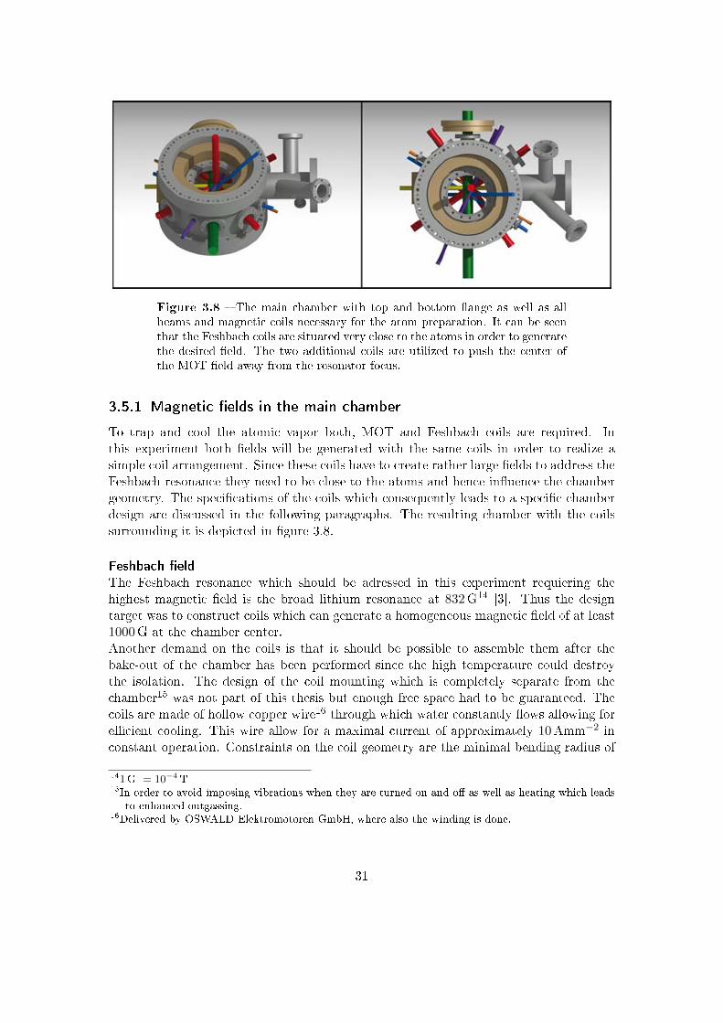
Figure 3.8 The main chamber with top and bottom ange as well as allbeams and magnetic coils necessary for the atom preparation. It can be seenthat the Feshbach coils are situated very close to the atoms in order to generatethe desired eld. The two additional coils are utilized to push the center ofthe MOT eld away from the resonator focus.
3.5.1 Magnetic elds in the main chamber
To trap and cool the atomic vapor both, MOT and Feshbach coils are required. Inthis experiment both elds will be generated with the same coils in order to realize asimple coil arrangement. Since these coils have to create rather large elds to address theFeshbach resonance they need to be close to the atoms and hence inuence the chambergeometry. The specications of the coils which consequently leads to a specic chamberdesign are discussed in the following paragraphs. The resulting chamber with the coilssurrounding it is depicted in gure 3.8.
Feshbach eld
The Feshbach resonance which should be adressed in this experiment requiering thehighest magnetic eld is the broad lithium resonance at 832G14 [3]. Thus the designtarget was to construct coils which can generate a homogeneous magnetic eld of at least1000G at the chamber center.Another demand on the coils is that it should be possible to assemble them after thebake-out of the chamber has been performed since the high temperature could destroythe isolation. The design of the coil mounting which is completely separate from thechamber15 was not part of this thesis but enough free space had to be guaranteed. Thecoils are made of hollow copper wire16 through which water constantly ows allowing forecient cooling. This wire allow for a maximal current of approximately 10Amm−2 inconstant operation. Constraints on the coil geometry are the minimal bending radius of
141G = 10−4 T15In order to avoid imposing vibrations when they are turned on and o as well as heating which leads
to enhanced outgassing.16Delivered by OSWALD Elektromotoren GmbH, where also the winding is done.
31

Figure 3.9 These calculations where performed to ensure that it is feasibeto generate the MOT (left) and Feshbach (right) elds with the same coils.Shown are the coil arrangement (top) and the absolute value of the mag-netic elds along the radial (bottom) as well as along the vertical (middle)direction each crossing the corresponding center position (units in Tesla andMeter respectively). The coils have an inner and outer diameter of 162mmand 224mm respectively, their spacing is 121mm and the current was set to10Amm−1 for the Feshbach eld and 5Amm−1 for the MOT eld (15Amm−1
for the additional pushing coil).
the wire (30mm for 4 × 4mm2 wire) and the maximal wire length which is determinedby the maximal length for which a constant water ow is possible.Simulations of the magnetic elds (gure 3.9) showed that it is best to use tubes for thetop and bottom ange which allow the coils to be brought closer to the position of theatoms than the overall high of the vacuum chamber.
MOT eld
In order to realize a simple coil arrangement the MOT eld should be generated with theFeshbach coils used in an anti-Helmholtz conguration. However, the MOT position isdisplaced with respect to the Feshbach coils hence additional coils are necessary to shiftthe position of the eld zero. Shifting the homogeneous Feshbach eld is not possible. Asuperimposed second homogeneous eld will only lead to a higher absolute value of theeld and a eld with a gradient which can shift the position of the eld maximum will
32

Figure 3.10 These mountings where developed to ensure a stable chambermounting and the possibility to assemble the magnetic coils after the bake-out. First the threading stick will be placed in special bores in the bottom ofthe main chamber. Then the upper part of the mount will be mounted andnally the chamber can be xed on the optical table with the lower part of themounts where the upper part is tightly clamped by the two vertical screws.
always impose inhomogeneities.For a MOT the magnetic eld gradient plays the key role and values of 5 − 15Gcm−1
are reasonable. Again some calculations where done to ensure that enough place is leftfor appropriate coils. The magnetic eld design was not part of this diploma thesis andtherefore the calculations depicted in gure 3.9 only state approximate values to ensurethe feasibility.
3.5.2 Chamber and resonator mounting
As mentioned above it should be possible to mount the coils after the chamber is bakedout which means that the chamber mounts must be detachable. For this purpose themounts depicted in gure 3.10 were designed. A vertical screw is provided for precisealignment of the chamber. The stability is guaranteed by clamping of the upper parttightly using the two horizontal screws.To mount the resonator base plate (4.3) four thread bolts are welded to the bottomchamber ange. They are positioned such that they do not block any beams and are notat the position of the mirror holders.
3.5.3 Vacuum pumps and materials
Choosing suitable vacuum pumps is a challenging task but not part of this diploma thesisso the interested reader is referred to [30]. In this experiment the vacuum is established
33

Figure 3.11 Shown are CAD-drawings of the nal vacuum chamber fromdierent perspectives. For orientation: The Zeeman slower will be mountedopposite to the large (pumping) tube and the glass cell in front of the leftpicture.
in three stages. Initially the chamber is evacuated by a turbo molecular pump where aoil-free version is chosen. The pump maintaining the nal vacuum at the main chamberduring experiment is an ion pump17. An interesting feature of this specic pump is theoptical passage provided by two oppositely placed CF100 ports. The ion pump will beactivated constantly and should be mounted as close to the chamber as possible prefer-ably with a large tube. In addition a titanium sublimation pump18 can be activated todeposit titanium on the inner surface of the chamber which then acts as a getter andabsorbs residual gases. This sublimation pump works best if it can deposite titanium inthe whole chamber but with 950 C it is quite hot and should therefore not be mountedtoo close to any temperature sensitive elements.While the pumps help to get rid of residual gases, it is the choice of materials that de-termine the composition of the residual gas by outgassing from the material. A furtheraspect which is important for this experiment is that the chamber material should nothave a high magnetic susceptibility since this would lead to perturbations in any appliedmagnetic eld yet for the experiments high precision is necessary. It is also important toconsider the processing when choosing a material in order to guarantee the producibilityof the chamber. Stainless steel is a common material oering both low magnetic suscep-tibility and low outgassing rates. From the variety of types diering slightly in specialproperties such as mechanical strength and chemical stability, the austenitic grades 304
17A 80 ls−1 nitrogen ion pump from Gamma Vacuum: 100L-DI-6D-SC-N-N Inventory: QM-00070.18Varian (Agilent Technologies): Mini Ti-BallTM Titanium Sublimation Source, Inventory: QM-00055
34

Figure 3.12 The vacuum system during assembling. The Zeeman slowertube, main chamber and ion pump can clearly be identied.
(V2, European norm: 1.4301) and 316 (V4, European norm: 1.4401 / 1.4436) are verycommon for vacuum systems where the latter is superior in both demands, low outgassingrates and low magnetic susceptibility. Nevertheless for this vacuum chamber 304 is uti-lized since the dierences seem marginal yet the price is much higher for 316.
35

4 The cooling resonator
Evaporative cooling is the key technique to achieve temperatures deep in the quantum de-generate regime. It can either be performed in magnetic traps or optical dipole traps bothshowing specic advantages and drawbacks. In the frame of this experiment fermionicatoms are investigated. Due to the Pauli principle two dierent spin states have to becaptured simultaneously for ecient evaporative cooling of fermionic atoms. For this ap-plication a dipole trap is favorable (2.1.5). Very deep traps are necessary for an ecientevaporation scheme. A large trap depth can be reached by enhancing the light eld ofthe dipole trap with a resonator. In this chapter the design of a ring resonator for anovel cooling scheme which will overcome drawbacks of other resonator dipole traps forevaporative cooling is reported.In the rst section (4.1) an overview of the relevant theory is given. The idea of theresonator and the working principle are then summarized in the second section (4.2).Finally this is followed by a detailed description of the design process and the technicalparameters (4.3).
4.1 Resonator theory
A resonator or cavity consists of two or more mirrors (reecting surfaces) arranged suchthat light can circulate between them. Since resonators play a key role within the newexperiment and this diploma thesis a detailed description of the properties of resonatorswill be given. A more comprehensive discussion can be found in [33] on which this chap-ter is based.In section 4.1.1 some general properties of resonators such as the nesse are derived wherethe plane wave approximation is applied. Subsequently the transverse eld amplitudedistribution in the resonator is discussed (4.1.2) and the result is used to obtain a condi-tion for a stable resonator geometry within the ray matrix formalism (4.1.3). Since everyresonator needs an active feedback to guarantee optimal incoupling eciency the Pound-Drever-Hall technique for frequency stabilization is introduced in section 4.1.4. As anexample the bow-tie resonator depicted schematically in gure 4.1 is utilized throughoutthis section.
4.1.1 Basic characteristics
An electro-magnetic wave incident on a mirror is split into a reected and a transmittedpart. The amplitudes of the electric eld are described by the complex transmissionand reection coecients t and r. They can be set to be real when the phase shift fortransmission in one direction is taken to be ei
π2 = i. For a lossless mirror t and r are
36

Figure 4.1 Schematic representation of a simple bow-tie ring resonator.The labeling of the incident eld Ei, the outgoing eld Eo and the circulatingeld inside the cavity Ec will be used in the whole thesis. The transmittedelds at the other mirrors are disregarded. The mirrors Mi are characterizedby their transmission coecients ti and reection coecients ri for the electricelds respectively.
then connected by r2 + t2 = 1.The following calculations are based on the scalar eld approximation describing theelectro-magnetic waves only by the amplitude of the electric eld (vector character andthe magnetic eld are neglected). For a steady state situation the cavity eld right behindthe incoupling mirror Ec must equal the sum of the transmitted part of the eld incidenton the mirror Ei plus the eld that has already made one roundtrip:
Ec = itEi + gEc (4.1)
with the complex net roundtrip gain g. For the example given in gure 4.1 it readsg = r2r3r4r1(1−α)eiφ where α is a general loss term taking into account the absorptionand scattering out of the resonator mode. α can be negative for an active medium placedinside the cavity (i.e. for a laser). For an empty resonator in vacuum with a roundtriplength L the phase φ is given by φ = ωL
c . For a lossless cavity (α = 0) the circulatingeld is then calculated to be1:
Ec =it1
1− |g|eiωLc
Ei (4.2)
Here one sees the resonance character directly because for ωres = 2πνres = p2π cL (pεZ)
a maximum in the circulating eld is given which can be much higher than the incident
1In general ri, ti, α φ and g all depend on the frequency of the electromagnetic wave ω. This is neglectto improve readability
37

eld. The same is true for the corresponding beam powers which are proportional to thesquare of the absolute values of the amplitude. The enhancement which is dened to bethe ratio of the incident power to the circulating power on resonance is then:
ε =PcPi
∣∣∣∣ωres
=t21
(1− |g|)2(4.3)
The resonance frequencies are called the axial resonator modes and the spacing betweentwo modes is the free spectral range: ∆ωf = 2π∆νf = 2π c
L . The linewidth2 of theresonance peak ∆ωl can be calculated by comparing the square of the absolute value ofequation 4.2 to one half of it's maximal value (e.g. for ω = ωres = 0) leading to:
1
2
∣∣∣∣ it1Ei1− |g|
∣∣∣∣2 =
∣∣∣∣∣ it1Ei
1− |g| ei∆ωl
2Lc
∣∣∣∣∣2
(4.4)
⇒ 2(1− |g|)2 =∣∣∣1− |g|ei∆ωl
2Lc
∣∣∣2 (4.5)
⇒ ∆ωl =2c
Larccos
(1− (1− |g|)2
2|g|
)(4.6)
≈ 2c
Larcsin
(1− |g|√|g|
)(4.7)
≈ 1− |g|√|g|
2c
L(4.8)
(4.9)
For the rst approximation it is used that cos(x) =√
1− sin2(x) and therefore arccos(1−x) = arcsin(
√2x− x2). Both approximations are valid for |g| ≈ 13. From the last
equality the nesse is given by:
F =∆ωf∆ωl
=∆νf∆νl
≈π√|g|
1− |g|(4.10)
Another quantity directly connected to the nesse is the ring-down time. When a res-onant beam is coupled into the cavity and is suddenly switched o at t = 0 the powerinside the resonator will show an exponential decay. This can be derived when start-ing with the loss of the electric eld amplitude for one roundtrip periode T inside theresonator, when no light is incident on the cavity:
∂Ec∂T
= −(1− |g|)Ec (4.11)
⇒ ∂Ec∂t
= − cL
(1− |g|)Ec (4.12)
⇒ Ec(t) = Ec,0e− cL
(1−|g|)t (4.13)
2Full width at half maximum.3Often the intensity reection coecient R = |g|2 is used.
38
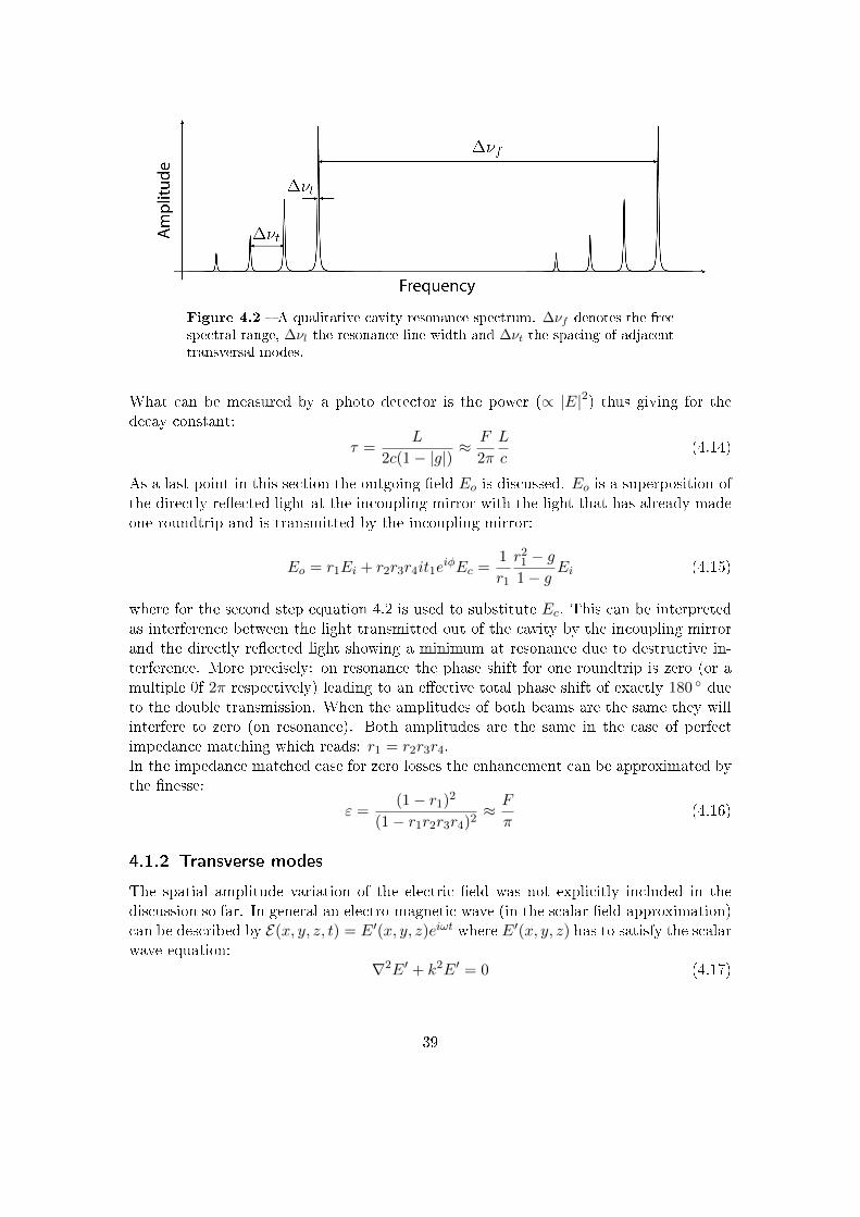
Figure 4.2 A qualitative cavity resonance spectrum. ∆νf denotes the freespectral range, ∆νl the resonance line width and ∆νt the spacing of adjacenttransversal modes.
What can be measured by a photo detector is the power (∝ |E|2) thus giving for thedecay constant:
τ =L
2c(1− |g|)≈ F
2π
L
c(4.14)
As a last point in this section the outgoing eld Eo is discussed. Eo is a superposition ofthe directly reected light at the incoupling mirror with the light that has already madeone roundtrip and is transmitted by the incoupling mirror:
Eo = r1Ei + r2r3r4it1eiφEc =
1
r1
r21 − g1− g
Ei (4.15)
where for the second step equation 4.2 is used to substitute Ec. This can be interpretedas interference between the light transmitted out of the cavity by the incoupling mirrorand the directly reected light showing a minimum at resonance due to destructive in-terference. More precisely: on resonance the phase shift for one roundtrip is zero (or amultiple 0f 2π respectively) leading to an eective total phase shift of exactly 180 dueto the double transmission. When the amplitudes of both beams are the same they willinterfere to zero (on resonance). Both amplitudes are the same in the case of perfectimpedance matching which reads: r1 = r2r3r4.In the impedance matched case for zero losses the enhancement can be approximated bythe nesse:
ε =(1− r1)2
(1− r1r2r3r4)2≈ F
π(4.16)
4.1.2 Transverse modes
The spatial amplitude variation of the electric eld was not explicitly included in thediscussion so far. In general an electro-magnetic wave (in the scalar eld approximation)can be described by E(x, y, z, t) = E′(x, y, z)eiωt where E′(x, y, z) has to satisfy the scalarwave equation:
∇2E′ + k2E′ = 0 (4.17)
39

with the wave number k = ωc = 2π
λ . Under the assumption that the amplitude E′(x, y, z)will only vary slowly with respect to the wavelength λ in the direction of propagation(e.g. z) this can be factored to E′(x, y, z) = E(x, y, z)e−ikz (where ∂2
∂z2E ≈ 0). Insertingthe latter into (4.17) gives:
∂2
∂x2E +
∂2
∂y2E − 2ik
∂
∂zE = 0 (4.18)
The boundary conditions for the individual solutions of this equation are determinedby the cavity. A stable mode has to show the same radial intensity distribution afterone roundtrip where a power drop due to losses and a phase shift is possible which ischaracterized in analogy to g by γ. This statement for a given z reads:
Ej+1nm = γnmE
jnm (4.19)
where the exact form of possible Enm depends on the geometry used and γnm = |γnm|ei(wLc−φnm).
The indices nm indicate the discreteness of solutions4. The phase is expressed by thephase of the central ray ωLc and a correction term φnm. On resonance the exponentialterm becomes unity and the new resonance frequencies are given by:
wres = 2πc
L(p+
φnm2π
) (pεZ) (4.20)
The magnitude of the correction φnm is typically much smaller than the free spectralrange. A schematic mode spectrum is shown in gure 4.2.The solutions to equation 4.18 under this boundary conditions are called transverseelectronic modes (TEMnm). The lowest order mode (TEM00) shows a Gaussian intensityprole so that the electric eld can be expressed by equation 2.11.
4.1.3 Geometric stability
The Gaussian mode discussed in the last subsection is a solution of the scalar waveequation in the paraxial approximation (paraxial Helmholtz equation). The propagationof a Gaussian beam can be described by the well known ABCD matrices from ray opticsas long as the elements fulll the paraxial approximation with respect to the beam radiusw(z). The Gaussian mode is fully characterized by a single parameter q which is givenby:
1
q(z)=
1
R(z)− i λ
πω(z)2(4.21)
Therefore the propagation through an arbitrary element can be described by the eectof this element on q leading to:
qo =Aqi +B
Cqi +D(4.22)
4The number of intensity minima in x and y direction is labeled with n,m respectively.
40
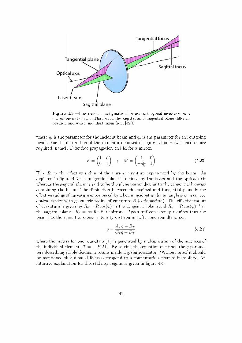
Figure 4.3 Illustration of astigmatism for non orthogonal incidence on acurved optical device. The foci in the sagittal and tangential plane dier inposition and waist (modied taken from [39]).
where qi is the parameter for the incident beam and qo is the parameter for the outgoingbeam. For the description of the resonator depicted in gure 4.1 only two matrices arerequired, namely F for free propagation and M for a mirror:
F =
(1 L0 1
); M =
(1 0− 2Re
1
)(4.23)
Here Re is the eective radius of the mirror curvature experienced by the beam. Asdepicted in gure 4.3 the tangential plane is dened by the beam and the optical axiswhereas the sagittal plane is said to be the plane perpendicular to the tangential likewisecontaining the beam. The distinction between the sagittal and tangential plane is theeective radius of curvature experienced by a beam incident under an angle ϕ on a curvedoptical device with geometric radius of curvature R (astigmatism). The eective radiusof curvature is given by Re = R cos(ϕ) in the tangential plane and Re = R cos(ϕ)−1 inthe sagittal plane. Re = ∞ for at mirrors. Again self consistency requires that thebeam has the same transversal intensity distribution after one roundtrip, i.e.:
q =AT q +BTCT q +DT
(4.24)
where the matrix for one roundtrip (T) is generated by multiplication of the matrices ofthe individual elements T = ....F1M1. By solving this equation one nds the q parame-ters describing stable Gaussian beams inside a given resonator. Without proof it shouldbe mentioned that a small focus correspond to a conguration close to instability. Anintuitive explanation for this stability regime is given in gure 4.4.
41

Figure 4.4 Schematic representation of a symmetric two-mirror resonatorwhich provides a focus. When the distance between both mirrors equals twicethe radius of curvature of the two mirrors the two mirror foci coincide andthe waist of the resonator mode is minimized. When the mirrors are broughtcloser together the beam waist becomes larger whereas extending the distancebetween both mirrors results in an unstable conguration since the resonatormode experiences strong losses. Please note that the stability region maybe characterized by a large distance between two curved mirrors for a ringresonator.
4.1.4 Frequency stabilization
Every resonator has well dened resonance frequencies (longitudinal modes) which areenhanced inside the cavity whereas all other frequencies are strongly suppressed. To guar-antee an ecient incoupling the laser frequency must coincide with the desired resonatormode. However, small uctuations in the eective resonator length or laser frequencylead to a dierence between the laser wavelength and cavity resonance. For high nessecavities the dierence between the laser frequency and the cavity resonance frequencyvery easily exceeds the linewidth of the cavity making an eective incoupling withoutan active feedback loop impossible. Such a feedback loop measures the deviation fromperfect resonance and corrects either the resonator length or the laser frequency. Theerror signal describing these deviations needs to give information about the total amountand the direction of the deviations. For an error signal only describing the strength of thedeviation it is not clear wether the laser frequency is above or below the cavity resonancefrequency and hence the feedback loop can not correct the deviation. Therefore the errorsignal needs to be asymmetric around resonance.A powerful technique available for this task is the Pound-Drever-Hall laser frequency sta-bilization (PDH locking technique). The theoretical basics of the error signal generationwith this scheme will be outlined in the following. More details can be found in [4].Neglecting the spatial dependence, the electric eld right behind the laser source can bedescribed by:
E = E0eiωt (4.25)
Modulating the phase of this electrical eld sinusoidal with frequency Ω and amplitudeβ results in:
E = E0eiωt+iβsin(Ωt) (4.26)
42

Figure 4.5 Plot of the real (top) and the imaginary (bottom) part of equa-tion 4.15 in the impedance matched case for dierent mirror reectivities andeld amplitudes (red: r = 0.99, Ei = 1 black: r = 0.9, Ei = 1 green: r = 0.9,Ei = 0.1). The lock is performed at the zero crossing of the imaginary part.Therefore a high nesse which leads to a short capture range as well as lowsignal strength wich causes a weak correction signal decrease the locking ca-pability.
Using Eulers formula and the small angle approximation for small β the electrical eldcan be approximated as:
E ≈ E0eiωt +
E0β
2ei(ω+Ω)t − E0β
2ei(ω−Ω)t (4.27)
This equation shows that a sinusoidal phase modulation is equivalent to adding sidebandsoscillating at frequencies ω ± Ω.Following subsection 4.1.1 the light observed as reection at the incoupling mirror ofa resonator is a coherent superposition of the light directly reected and the leakagefrom the light inside the resonator. Comparing the reected light with a phase referencetherefore enables to extract the phase dierence between directly reected light and thelight transmitted from inside the cavity. Sidebands can be used as the phase referencewhen the modulation frequency is large enough that the sidebands are totally reectedwhenever the main frequency is near resonant. To extract the phase shift induced on thecarrier frequency due to the presence of the resonator, the outgoing light at the cavityis monitored by a photodiode. Demodulating the signal with the frequency used for
43

sideband generation and ltering it with a low pass yields the error signal.More precisely, the outgoing light at the incoupling mirror can be written as:
Eo = F (ω)Ei (4.28)
where the transfer function F (ω) is dened by equation 4.15. When plotting this function(gure 4.5) it can be seen that the amplitude of the reected light (∝ Re(F )) is symmetricaround the resonance whereas the phase (∝ Im(F )) is asymmetric and linear near theresonance, yielding the desired error signal.The statement that the sidebands are totally reected is equivalent to F (ω ± Ω) = −1.Together with equation 4.28 and the special case of the incident light eld in equation4.27 the outgoing eld from the cavity can be written as:
Eo = E0
(F (Ω)eiω − β
2ei(ω+Ω)t +
β
2ei(ω−Ω)t
)(4.29)
A photodetector measures the power which is proportional to the square of the absolutevalue of the eld amplitude |Eo|2. Neglecting terms quadratic in β (appropriate for smallβ) and using Eulers formula again, the power of the outgoing eld at the incouplingmirror of the cavity can be expressed as:
Po ∝ |Eo|2 (4.30)
≈ |Ei,0|2(|F (ω)|2 + iβ[F (ω)− F (ω)∗] sin(Ωt)) (4.31)
= |Ei,0|2(|F (ω)|2 − 2βIm[F (ω)] sin(Ωt)) (4.32)
with Ei being the amplitude incident on the resonator. The photocurrent and hence theelectrical signal Sr is directly proportional to the measured power. In order to extractthe nal error signal the photodiode signal Sr is demodulated with the (phase shifted)frequency for the sideband modulation in a frequency mixer5 and low pass ltered whichresults in the dc component of the signal. Mathematical these steps are described by:
Sr ∝ |Eo|2 (4.33)
Smixr ∝ Sr sin(Ωt+ ϕ) (4.34)
Sdcr ∝ −2|Ei,0|2βIm[F (ω)] cos(ϕ) (4.35)
In an ideal case no phase shifter to adjust ϕ is required but in most realistic situations aphase dierence between the signals used to generate the sideband and for demodulationis present (e.g. due to dierent signal path length) which needs to be compensated.Finally the error signal is fed back to either change the cavity length or the laser fre-quency keeping the cavity in resonance with the laser frequency. An overview of thewhole scheme can be seen in gure 5.6.Translating the error signal into a change in resonance frequency respectively laser wave-length can be achieved via dierent methods. For example a piezoelectric element trans-lating one of the resonator mirrors can correct for relatively large frequency deviations,5Frequency mixing is mathematical described by multiplication of both signals.
44

Figure 4.6 Schematic overview of the Pound-Drever-Hall frequency stabi-lization. An electro-optical modullator (EOM) modulates sidebands on a laserbeam incident on a cavity. The reected light is collected by a fast photodiode(PD) and the signal is demodulated in the mixer with the EOM driving fre-quency from a local oscillator (LO). The error signal is fed into a PI controllerwhich drives a correction element (a piezoelectric actuator at one of the cavitymirrors for instance).
i.e. changes comparable to the desired wavelength. Unfortunately the regulation band-width of piezoelectric actuators limits the correction speed to frequencies of some tenthof Kilohertz. By adding an acousto-optical modulator in the beam path and adjustingits driving frequency it is possible to tune the laser frequency by hundreds of Kilohertzwith a bandwidth on the order of a Megahertz. Another option is to adjust the laserwavelength directly for example by means of changing pump diode current, the crystaltemperature or the length of a laser cavity.
4.2 Design considerations
To enhance the eciency of the evaporative cooling a novel scheme based on a dipoletrap formed by a ring resonator will be implemented. The transfer of the atoms from theMOT into the dipole trap will be performed outside of the resonator focus at a ratherlarge beam diameter whereas the evaporation is performed in the focal region which leadsto enhanced thermalisation rates.The two crucial points for an ecient loading are the trap depth and volume at the MOTposition. For a given element and wavelength the rst one only depends on the powerinside the resonator which can be adjusted via the resonator nesse assuming a givenavailable laser power and transfer volume. The transfer volume depends on the osetfrom the focus and the beam waist as can be seen from equation 2.12.As mentioned in section 4.1.3 a small waist correspond to a conguration close to theinstability region. For congurations close to the critical point, however, already small
45

changes in the resonator length may lead to an instable resonator. Therefore the minimalbeam waist is determined by the ability to adjust and stabilise the resonator length6. Fortypical experimental situations a waist of approximately 20µm is reasonable. For thisminimal beam waist the loading volume only depends on the oset from the resonatorfocus. A small focus not only leads to a large loading volume but also yields high trapfrequencies at the focus region which determine the thermalisation rate and thereby theeciency of the evaporation.The depth of the dipole trap is determined by the nesse of the resonator. The nessealso has an impact on the stability of the frequency lock as mentioned in section 4.1.4.To guarantee an ecient frequency stabilization and simultaneously a high enhancementa nesse of approximately 2000 was chosen for this resonator. A typical anti-reectioncoating for vacuum viewports has a transmissivity of approximately 99 % which onlyallows for a nesse of maximal F ≈ 40 when the resonator is placed outside the vacuumchamber (eectively eight viewports inside the resonator). The consequence of this isthat the resonator has to be placed inside the vacuum which leads to strong restrictionsfor the mechanical design.The controlled translation of the atoms in the interference pattern is induced by a fre-quency detuning δν between the two counter propagating beams. The associated velocityis given by:
v = δνλ (4.36)
This equation implies that during the transport at least one beam is not in perfectresonance with the cavity. However, in order to maintain a perfect interference patternboth beams inside the resonator have to be stabilized to the same intensity. As longas the detuning is not too large, i.e. comparable to the linewidth of the resonance, thiscan be easily achieved by monitoring both beams and correcting for dierences in thecirculating power by adjusting the power incident on the resonator.Equation 4.36 also shows that the transport velocity is limited by the resonance linewidthof the resonator which is determined by the nesse. Another limitation for the velocityoriginates from the requirement that the transport should be adiabatic. An adiabatictransport is guaranteed when the corresponding time scales are much larger than thetime scales associated with the oscillations of the atoms in the trap.
4.3 The design process
After the general considerations about the evaporation scheme in the last section a closerlook on the specications of the actual cavity will be given now. First the requirementson the resonator are summarized:
• A small focus is crucial since it not only leads to high trap frequencies for evapora-tion but also denes the divergence and thereby the volume at the MOT Position(for a given transport distance).
6The distance between the two curved mirrors is the sensitive length.
46

• A high nesse is required to achieve the desired trap depth. However, the nesseshould not be so high as to make the frequency stabilization very challenging.
• A stable mounting of all parts is necessary to avoid instabilities through vibrationsor misalignment over longer timescales.
• A piezoelectric actuator behind one mirror is required for frequency stabilization.
• The resonator must t into the vacuum chamber.
In the following subsection it will be shown how the rst statements inuence the res-onator geometry and mirror selection (4.3.1). This consequently leads to a specic designof the mirror holders which will be topic of subsection 4.3.2 where the stable mountingis discussed as well. Finally the problem of a suitable piezoelectric actuator is addressed(4.3.3). The vacuum chamber will be treated as a given restriction although the designwas actually done in parallel.
4.3.1 Finding the optimal parameters
In this section it will be described in detail how the nal resonator parameters were found.It starts with the choice of an overall geometry followed by a discussion of the speciclengths and angles. Finally the problem of nding appropriate mirrors is addressed.
Resonator type
A ring resonator with three or more mirrors is required to allow for the transport. Sincethe beam propagation in a ring resonator is not orthogonal to the curved mirrors theeective radius of curvature in sagittal and tangential directions are distinct (see section4.1.2). The dierence in the eective mirror curvature leads to an elliptical gaussianmode as can be seen from the propagation matrices (equation 4.23). The beam becomesmore elliptical when the angles of incidence on the curved mirrors rises. Because of theellipticity the beam waist dier in the both direction making it dicult or even impos-sible to create a very small focus in both directions. Therefore the angle of incidence onthe two curved mirrors should be as small as possible.The simplest ring resonator geometry providing a small angle of incidence on two curvedmirrors is the bow-tie resonator already schematically depicted in gure 4.1. Neverthe-less a non-negligible angle and corresponding ellipticity is inevitable due to the physicalextent of the mirrors. For given mirrors this angle depends only on the distance betweenthem. The minimal mirror diameter in turn depends on the beam divergence and thedistance between the mirrors.
Resonator dimensions
A small focus implies that the resonator is very close to the instability region and thedistance between the curved mirrors roughly equals the radius of curvature. Since highquality mirror substrates7 are only available with certain radii of curvature this require-7Here super polished substrates from ATFilms are chosen.
47

Figure 4.7 Overview of the resonator specications. The radius of curvatureof mirrors M3 and M4 is 200mm, M1 and M2 are plane parallel. The reectioncoecient for 1064nm radiation are measured to be approximately 99, 85 %for M1 and M2 and 99, 998 % for M3 and M4 respectively.
ment restricts the size of the resonator to these particular values. Other limitations tothe mirror distance arise from the fact that the whole resonator has to be placed insidethe vacuum chamber.After some iterations nally the values given in gure 4.7 turned out to give the best com-promise satisfying the requirements. A calculation of the beam radii in both directionsfor this conguration can be seen in gure 4.8. The program used relies on equations4.22 to 4.23 and was developed by Robert Jördens. It can be seen that the beam waist is20× 30µm whereas the radius at the MOT position is 230× 340µm. The choice of theright MOT position relies on many parameters such as sucient beam waist, optical ac-cess and so forth and was found to be optimally located 20 mm away from the resonatorfocus.
Mirror reectivities
The resonator will be placed inside the vacuum chamber. Therefore losses inside thecavity can be neglected and the nesse only depends on the reectivity of the resonatormirrors. Since the beam at the curved mirrors is strongly divergent the incoupling andpower monitoring will be performed at the plane parallel mirrors8. For this reason thecurved mirrors are chosen to be highly reective and the nesse is determined by the planeparallel mirrors only. Taking the requirement for impedance matching (r1 = r2r3r4) intoaccount the reectivity of these mirrors should be approximately equal and given by|ri|2 = 99, 85 %. The transmission curves as measured by the manufacturer are shown
8Only once the beam divergence is measured at one curved mirror in order to calculate the exact beamwaist.
48

Figure 4.8 The calculated beam radius (in mm) in sagittal (blue) andtangential (green) direction for the resonator geometry indicated in gure 4.7.The inlet shows that tight focussing is equivalent to strong divergence.
in gure 4.9. For the plane parallel mirrors a reection coecient of approximately|ri|2 ≈ 99.85 % and for the curved mirrors of approximately |ri|2 ≈ 99, 992 % is speciedfor a laser wavelength of 1064 nm. With equation 4.10 this yield a nesse of approximatelyF ≈ 1987. The free spectral range of the resonator can be calculated with the resonatorlength L ≈ 0.86m to be ∆νf ≈ 349MHz. This free spectral range together with thenesse gives a resonance linewidth of ∆νl ≈ 176 kHz. The transport of the atoms fromthe MOT position to the focus thus takes a minimal time of approximately 0.2 s forδν = 0.5∆νl. With the mirror reection coecients given above an enhancement ofroughly ε ≈ 633 is calculated. For 6Li, a laserwavelength of 1064 nm and a realisitcpower per beam of 1W this enhancement lead to a maximal trap depth at the MOTposition in the two counter-propagating beams of approximately T ≈ 1.2mK and trapfrequencies of ωx ≈ 1.8 kHz, ωy ≈ 1.2 kHz and ωz ≈ 1.7MHz respectively. The samecalculations for the focus position with only one beam yield a maximal trap depth ofT ≈ 40mK and trap frequencies of ωx ≈ 119 kHz, ωy ≈ 79 kHz and ωz ≈ 1.1 kHzrespectively.
4.3.2 Mechanical realization
For the mechanical mounting of the mirrors many constraints have to be fullled. Thestrongest restriction is that the resonator has to be placed inside the vacuum becausethis limits the available space to the inner dimensions of the chamber. The vacuumalso inuences the choice of material since outgassing has to be avoided. Even morerestrictions follow from the fact that the optical access for all desired beams has to be
49

Figure 4.9 The transmission coecient for normal incidence for the planeparallel mirrors (left) and for the curved mirrors (right) as measured by Lay-
ertec. At a wavelength of 1064nm the power reection coecients |r|2 arespecied to be 99.85± 0.05 % and > 99.992 % respectively.
kept free. Overviews of the whole resonator assembly as planned and manufactured canbe seen in gure 4.10 and 4.12 respectively. In the following a detailed description of thedesign process is given. The mounting of the piezoelectric actuator is discussed separatelyin subsection 4.3.3.
Orientation
The direction of the focused resonator beam and thereby the position of the mirrors isdened by the axis of transport to the nal experiment. The reason for this is that a goodoverlap between the elongated dipole traps of the resonator and for transport is crucialto assure an ecient loading of the transport trap from the resonator trap. Consequentlya small angle between both beams is favorable. This angle was minimized to be approx-imately 25 . Thus a perfect overlap is not given but this should not matter too muchsince the atoms should ow from the resonator trap into the focus of the transport beamwhen the resonator trap is ramped down and the transport dipole trap is simultaneouslyramped up.Another point to be kept in mind when positioning the individual mirrors is that thewhole resonator roundtrip should lie within one plane. Otherwise the polarization willchange in a way not well controllable which then also inuences the resulting interferencepattern. Taking the available space into account this plane was found to be optimallysituated when tilted by 8 with respect to the vertical plane.
Mounting
For aligning and testing purposes the whole resonator will be assembled outside the vac-uum chamber and afterwards inserted without realigning. This requires stable mountingof all mirrors on the same ground plate. The ground plate can be seen in gure 4.10.
50

Figure 4.10 CAD drawings of the resonator ground plate, the mirror hostsand the individual mirror holder (top, from left to right). In the lower panel theassembled resonator (right) with all rays crossing the main vacuum chamber(left) is shown.
The large hole in the middle and the groove in the front of the drawing are included tomaintain all optical access, which also limits the overall height of the ground plate. Toavoid virtual leaks the ground plate only stand on small bridges (0, 5mm wide). It isxed to the bottom chamber ange by the thread sticks welded on the bottom chamberange.It is convenient to x the two mirrors of each resonator side to one common structure(host) which is mounted on the base plate. The mirror holders will be held by four strongsprings where the adjustment is enabled by three ne threading screws. Although theresonator alignment will be performed outside the vacuum chamber the screws should beaccessible after inserting the resonator into the chamber in order to enable readjustment.Therefore the mirrors are mounted behind the hosts (looking from the focus). Of courseit is important that none of the beams inside the chamber is blocked by the hosts whichis especially important for the incoupling and monitoring beams as well as the circulatingbeams itself. The hosts created for this purpose are shown in gure 4.10 and gure 4.12.It can be seen that the holes designed for the mounting on the base plate are elongated.The elongated holes makes it possible to adjust the length of the resonator and therebythe beam waist on a larger scale than it is possible with the adjustment screws.
Mirror holders
The mirror holders themselve have to satisfy constrains in addition to the spatial limi-tation. First of all the back sides of both plane parallel and one curved mirror have tobe accessible to enable incoupling, power and mode monitoring respectively. The fourth
51

Figure 4.11 CAD drawings of the holder designed to mount a mirror on thepiezoelectric actuator without glue. The mirror holder is clamped to the piezo-electric tube with the help of a plate spring. To not damage the piezoelectricmaterial during assembling it is important that no shear forces or radial loadis applied to the piezoelectric tube.
mirror will be equipped with a piezoelectric actuator for frequency stabilization whichwill be the topic of subsection 4.3.3.Optimal adjustability is achieved via three screws. It is important that the center of thespring forces xing the holders to the hosts lies within (most likely centered) the triangleformed by the screws to ensure proper tilting in both directions as well as translation.For optimal position stability it is convenient to restrict the movement of the screw tipson the holder by providing a cone for one screw (xed position) and a groove for oneother (one-dimensional movement) as can be seen in gure 4.10. The mirrors are xed tothe holders by setscrews. At the side opposite to the set screw an o-center bore ensuresthat exactly two contact points exist which guarantee stable positioning.
Adjustment screws
The mirror adjustment screws provide a problem not yet mentioned. In the vacuumof course no grease can be applied but still an easy and precise adjustment has to beensured. Precise adjustment without grease, however, is impossible when the threadinghole and the screw are made from the same material. Since stainless steel is used forthe base plate the mirror holders and the hosts some dierent, self lubricating materialis required for the screws which shows only small outgassing. A bronze alloy (CuSN8P)was chosen for this purpose. The specially manufactured screws are depicted in 4.12:the tip consists of a stainless steel ball which is inserted in a cone at the front end of thescrew.
52

4.3.3 The piezoelectric actuator
For the PDH lock the resonator length has to be adjustable in order to correct foructuations. A convenient way to do this is to mount one of the mirrors on a piezoelectricactuator. Since power monitoring and incoupling are performed with light transmittedthrough the at mirrors a curved mirror is equipped with the piezoelectric tube. For theperformance of the stabilization this is a good choice as well since the distance betweenthe two curved mirrors is the sensitive length.
Piezo electric material
Since the piezoelectric eect depends on the electric eld amplitude stack type actua-tors are typically used because they allow for large length variations with low voltages.Unfortunately such stacks need to be isolated for testing purpose under atmosphere, yetmost isolation materials are not compatible with UHV conditions9. For one-crystallinepiezoelectric tubes the expansion is given by:
∆L ≈ d31LU
d(4.37)
where U is the applied voltage and d the wall thickness. The material NCE55 fromNoliac oers a high piezoelectric coecient of d31 = −260× 10−12 CN−1 and is availablewith custom specications. A special size is required since the space behind the mirrorsis strongly limited and standard tubes where not available with the given dimensions. Atube of 9mm length with a wall thickness of 1mm thus allows for a length variation ofapproximately 1000 nm when a voltage of ±200V is applied.
Piezo tube holder
Since glues have considerable outgassing rates and limited long time stabilities a purelymechanical mounting was designed. For the construction of a mount for a piezoelectricactuator attention has to be paid to the fact that piezoelectric materials are very sensi-tive to shear forces and radial pressure. Therefore the only possibility to properly mountthe tube without glue is to strongly clamp it in longitudinal direction. Additionally thispreload enhances the resonance frequency and thereby the speed of the piezoelectric ac-tuator. Because of their small size and relatively strong forces plate springs are optimallysuited to clamp the piezoelectric tube. The contact planes of the plate springs form acone to ensure that the plate springs and thus the piezoelectric tube stay on the trans-lation axis and no tilting is possible.The mirror holder designed to hold the piezoelectric actuator can be seen in gure 4.11.During assembling it is crucial to ensure that the two parts clamping the piezoelectrictube are not rotated with respect to each other. Instead only the part to x the holderat the hosts should be moved. Of course it is important that the wires delivering thevoltage are isolated with kapton which is an UHV suitable plastic.
9Physical Instruments species their Picmar ceramics to be UHV suitable but to our knowledge thiswas never been tested under comparable experimental conditions.
53

Figure 4.12 Pictures of the manufactured elements for the resonator. AEuro coin is shown for scale reference. The small wall on the right side ofthe lower hole in the left host prevents the titanium sublimation pump fromdeposing titanium on the mirror surface.
54

5 Testing the resonator
To reach the desired trap depth for evaporative cooling with moderate laser power theenhancement of a resonator placed inside the vacuum chamber is used. The utilizedcooling scheme demands for precise control of the power and frequency in the two in-coupled beams. The control of the frequency is necessary to enable the transport andthe frequency stabilization whereas the power has to be adjustable in order to enablethe evaporation and to hold the power in both beams constant during the transport.Therefore sophisticated control electronics (5.2) and an appropriate optical setup (5.1)are required.A crucial point for every cavity is the frequency stabilization which is especially chal-lenging for a large high nesse cavity like the cavity employed in this experiment. Toguarantee the feasibility of the locking scheme as planned a setup including all desiredelements was built. First measurements characterizing the resonator and the feedbackloop are performed on this setup and presented in the nal section (5.3). Although thereare some theoretical details on a few elements the focus of this chapter lies on the workin the lab. It should be pointed out that all the work was performed on a test setup andsome details may still be changed.
5.1 Optical setup
The optical setup for the operation of the cooling resonator includes the EOM whichgenerates the sidebands for the Pound-Drever-Hall frequency stabilisation and two AOMswhich are employed to prepare the two beams for the resonator as well as beam shapingoptics and mirrors to guarantee an ecient incoupling. Before setting up the test systeman overview of the optical table including all elements potentially aecting the plans forthe cooling resonator optics was drawn. In particular this was necessary since the samehigh power laser source will be utilized for the cooling, transport and manipulation ofatoms. Several main components are described at the end of this section (5.1.2 to 5.1.5)in detail but rst the whole optical system is summarized (5.1.1).
5.1.1 Layout of the optical setup
The optics for the preparation of the two beams which are coupled into the resonator areplaced on the same optical table as the vacuum system and the cavity. The laser radiationis provided by a high power solid state laser with a very good beam prole. Neverthelessbeam shaping optics are planned to guarantee an ecient incoupling. The optical setupalso include two acousto-optical modulators (AOM) which will be utilized for the powercontrol of both beams and together with an electro-optical modulator (EOM) form the
55

Figure 5.1 A scaled view of the experimental table as planned so far. Thedimensions of the table are: 3.5× 1.5m. The vacuum system and the opticalsetup are shown. For a detailed discussion see text.
fast part of the feedback loop. Additionally the beam preparation for the dipole trapemployed to transport the atoms into the glass cell is considered since it strongly aectsthe space available for the other elements. In the following a detailed overview of everyelement in the beam path is given.A sketch of the experimental table as planned so far can be seen in gure 5.1. A Nd:YAGsolid state laser generates approximately 25W of laser light at a wavelength of 1064 nm(for details see 5.1.2). An optical isolator is placed right behind it to prevent back re-ections into the laser. Since optical isolators are polarization dependent, wave platesare used to adjust for best transmission. In fact, every polarization dependent elementlike EOM, AOM and polarizing beam splitter has a wave plate in front of it to set theright polarization. Additionally, space is kept free for a second, optional optical isolatorin case the present 35 dB attenuation is insucient.The next main element is an electro-optical modulator which generates the phase mod-ulation for the Pound-Drever-Hall (PDH) signal. The rst acousto-optical modulatorsplits o the laser beam for the transport dipole trap. This is then coupled into anoptical ber to maintain a perfect TEM00 mode. At the outcoupling port of the ber apolarizing beam splitter for polarization ltering and power monitoring via a photodiodefollow before the beam is expanded and focused into the chamber by a lens mounted onthe translation stage.At the main beam path the AOM is followed by a wave plate, which can be rotated bya small motor, and a beam splitter. One of these beams is then guided away for furtheruse. The beam splitter is followed by two AOMs providing the two beams for the coolingresonator. Both beams are then guided through a telescope for better mode matchingand a periscope which shifts the beam path to the height of the resonator in the vacuumchamber (28 cm).The nal incoupling is achieved via two independent mirrors for each beam to ensure full
56

control over direction and position of the beam at the incoupling mirror (beam walk).Two wave plates with polarizing beam splitters are used to ensure the right polarizationand thereby a clean interference pattern inside the resonator (not shown). The beamsplitter and the photodiode provides the signal for the PDH lock explained in 4.1.4.Some mirrors for the incoupling of the MOT beams were also considered. Two photo-diodes for monitoring the intensity of each beam independently (required for the powercontrol) are placed behind the outcoupling port of the resonator (not shown).
5.1.2 The laser source
The laser source utilized for the evaporation dipole trap has to fulll some requirements.For example a narrow linewidth is desirable in order to enable an ecient incouplinginto the high nesse cavity and good frequency stability is favorable to relive the Pound-Drever-Hall feedback loop. Additionally high power is necessary to generate a deep trapfor evaporation. Even more power is necessary since the same laser source will also beused to form the dipole trap for the transport of the atoms into the glass cell and togenerate optical lattices in the glass cell. In the nal setup a 25W Mephisto [36] lasersystem from Innolight will be used for this purpose but in the test setup a much smallerversion with only 200mW output power is employed. However, most other specicationsare comparable and it will be referred to the 25W version in the following.The high power Mephisto systems consists of a Nd:YAG (neodymium-doped yttriumaluminum garnet) solid-state laser [34] followed by additional optical ampliers. Thisso-called master oscillator power amplier (MOPA) approach preserves the advantagesfrom a single weak laser source while quite high powers can be reached1. For examplea very good single mode (TEM00) operation and beam prole is specied. The laseremits at a wavelength of 1064 nm with a narrow linewidth of only 1 kHz. Two optionsfor frequency tuning are included: The eective cavity length can be changed by apiezoelectric actuator leading to a frequency tuning range of ±100MHz and a responsebandwidth of 100 kHz. A change of the laser crystal temperature leads to a tuning rangeof 30GHz where the response bandwidth is limited to approximately 1Hz. In the testsetup the lock was performed only with the piezoelectric actuator and the temperaturecontrol was utilized for manual adjustment. Other important characteristic of this lasersource are the frequency stability (specied to approximately 17 kHzs−1) and the verylow intensity noise (< 0.2 %rms from 10Hz to 2MHz).
5.1.3 Electro-optical modulators
For the Pound-Drever-Hall frequency stabilization scheme a modulation of the phase ofthe laser light is necessary. This phase modulation is generated by an electro-opticalmodulator. In general every device which modulates the properties (phase, frequency,amplitude, polarization) of a beam of light by use of an applied electric eld is called anelectro-optical modulator (EOM). Here, however, EOM refers to what more precisely is
1Diode stacks and ber lasers with comparable powers for instance typically show much worse beamproles.
57

Figure 5.2 Pictures of the EOM employed in this setup. In the front view(left) the crystal can be seen. The three coils for incoupling and monitoring arewrapped on a common structure (right). Everything is xed with an isolatingstructure.
an electro-optical phase shifter.An electro-optical phase shifter consists of a crystal whose refractive index and the relatedspeed of light depend on the local electric eld (Pockels eect, Kerr eect). The phaseof a laser beam behind a crystal in turn depends on the optical path length. Thereforean EOM can modulate the phase of the outgoing laser beam by modulating an externalelectrical eld [13].Pictures of the EOM employed in this experiment during assembly can be seen in gure5.2. The electrical eld is generated by a parallel plate capacitor placed across the crystal.Together with a coil it forms a resonant circuit enhancing radio frequencies which arecoupled in through a second coil from an external source. A third coil can be used formonitoring. The measured resonance frequency of this EOM is 68MHz with a linewidthof 1MHz.
5.1.4 Acousto-optical modulators
An acousto-optical modulator (AOM) can be used to tune the frequency and amplitude ofa laser beam. In the frame of this work AOMs are utilized for the fast part of the Pound-Drever-Hall frequency stabilization and the frequency control enabling the transport aswell as for the power control. Figure 5.3 schematically shows the working principle of atypical acousto-optical modulator. A piezoelectric actuator is mounted on a transparentmaterial such as glass. When an oscillating voltage is applied to this actuator it startsvibrating and thus generates a sound wave inside the glass. Back reections are sup-pressed by an acoustic absorber on the opposite side. The acoustic (density) wave insidethe material causes a periodic change in the refractive index. This acts as a grating toan electro-magnetic wave traveling perpendicular to the acoustic wave leading to typicaldiraction phenomena.The power in the diracted beams can be adjusted by the amplitude of the acousticwave. With a thin piece of material, pure sinusoidal modulation and careful adjustment
58

Figure 5.3 Working principle of an acousto-optical modulator. The vi-brations of a piezoelectric actuator lead to a travelling density wave insidea piece of glass. A beam of light will diract at the grating formed by thedensity wave and the resulting modulation of the refractive index respectively.In contrast to Bragg diraction at conventional gratings the frequencies ofthe diracted beams in an AOM are shifted due to the conservation of mo-mentum in the photon-phonon interaction which causes the diraction in aquantum-mechanical picture.
up to 90 % can be diracted into the rst order depending on the specic AOM.An important dierence to conventional Bragg diraction is the traveling wave natureof the grating which leads to a Doppler shift in the diracted beams. In other words,momentum and energy are conserved in the photon-phonon interaction. The frequencyshift is given by the modulation frequency and can vary between approximately ten anda few hundred Megahertz for dierent types of AOMs. This eect also makes it possibleto tune the laser frequency by changing the AOM driving frequency. Please notice thatin a given optical setup the frequency can only be tuned by up to a few MHz since theangle of diraction is also dependent on the frequency so that a large shift would resultin misalignment.In many applications the speed of an optical device is a crucial point. For AOMs thisonly depends on the beam radius and the speed of sound inside the material and can berather fast. For the AOM used in this setup a reaction time of approximately 0.37µs isexpected. For this test setup a AOM with a driving frequency of 80MHz was used2. Themaximal observed diraction eciency was near 85 % where it was obvious that furtherimprovement is possible.
59

Figure 5.4 The resonator test setup with the drawn beam path. The CCDcamera is visible in the upper right corner.
5.1.5 The test resonator
A sophisticated cavity was designed to ensure good mechanical stability and a suitableresonator geometry. Unfortunately the production of the mirror holders was not nishedwhen the work in the lab started so that a test resonator was built. It consists of thenal mirrors but conventional mirror holders. It was tried to make this test resonatorgeometrically as similar to the nal resonator as possible but some dierences whereinevitable. For example, the angles between the dierent beams where larger due tothe larger mirror holders. Also the distance between the two curved mirrors was largerresulting in an optically more stable conguration but also in a larger beam waist. Amore serious dierence between the nal resonator and this setup was the obviously muchgreater mechanical instability of the latter one. Additional no piezoelectric actuator wasmounted at the resonator mirrors such that the locking was implemented by changingthe laser wavelength directly. In the nal setup the frequency stabilization will not beperformed by tuning the laser frequency since the laser has to be locked simultaneous todierent cavities.For the alignment of an infrared resonator team work is recommended since observationof the beam and adjusting the elements needs more than two hands. The alignment wasperformed in the following way: First of all, the two at mirrors were lined up with thelast mirror before the resonator such that all of them were centrally hit by the beam. Forthe observation of the beam behind the incoupling mirror the room has to be darkenedand the utilized infrared viewer card needs regular recharging. As a second step alsothe curved mirrors were placed and an approximate roundtrip is achieved by moving themirror holders.Once this is done, the holders are xed tightly onto a ground plate and further adjust-ment is performed with the appropriate screws at the resonator. By guiding the main
2Gooch & Housego: I-FS080-2S2G-3-LV1, Inventory: QM-00079
60

Figure 5.5 Schematic overview of the electronic scheme employed for theoperation of the cooling resonator. The error signal generation is discussedin detail in section 4.1.4. The slow part of the feedback loop will be im-plemented through a piezoelectric actuator translating one of the resonatormirrors whereas the fast part will be implemented with two AOMs placed inthe beam path. The frequency control to make the controlled transport of theatoms inside the resonator possible and the power control to enable the evap-orative cooling will be implemented through the same AOMs as the frequencystabilisation.
beam inside the resonator through a small hole in the viewer card the light of higherorder roundtrips can be observed. This is brought to overlap with the main beam bysuccessively adjusting each mirror. When no further improvement was possible in thisway a CCD camera was placed behind the second at mirror. After some adjustmentof the incoupling (remember the original mirror positions!) the TEM00 mode could beobserved and optimized to a certain extend.Since observation of the light transmitted by the resonator with a viewer card is impos-sible in the unlocked mode, then the monitoring of the reected light was set up. Oncethe resonator is locked a photodiode can be added behind the outcoupling mirror givingprecise information on the power circulating inside the resonator. Now the incouplingcan be improved again by carefully adjusting each mirror. Finally the monitoring of thereected light has to be readjusted.The incoupling of the second beam was not performed but it should be easier since theresonator stays unchanged and the requested overlap with the reected part of the rstbeam should help.
5.2 Electronic setup
For every resonator electronics are necessary to realize the frequency stabilization. Forthe resonator discussed in this thesis even more electronics are needed to realize thetransport and evaporation for the novel cooling scheme (gure 5.5). The frequencystabilization scheme implemented for this resonator can be divided into three parts.First a Pound-Drever-Hall error signal is generated by demodulating the light reectedon the incoupling mirror of the cavity with the local oscillator which drives an EOMmodulating sidebands on the incident laser beam. Second a slow feedback is realizedwith a piezoelectric tube translating one of the cavity mirrors such that rather largedisturbances can be corrected by changing the resonator length. Finally a fast feedback
61

Figure 5.6 Detailed overview of the electronic scheme employed for theoperation of the cooling resonator. One sees the elements for the error signalgeneration (red) and the slow part of the feedback loop (green) as well as thefrequency (blue) and power (yellow) control for the AOM driving frequency.The given abbreviations stand for: PD = photodiode; RF = RF-lock; AMP= amplier; FG = frequency generator; PI = PI-controller; U = DC voltagesource. For further explanations see text.
is implemented with an AOM placed in the beam path which shifts the laser frequencywhen the AOM driving frequency is changed. The AOM can only correct deviationsfrom resonance with a relative small amplitude but it perfectly complete with the slowfeedback by the piezoelectric element. For the evaporative cooling it is necessary tolower the power circulating in the cavity. The power control for this purpose is realizedby adjusting the amplitude of the driving frequency for the two AOMs which splits up thepower for the two resonator beams from the primary laser beam. The same AOMs areused to realize the fast part of the frequency stabilization and additionally to introducethe frequency dierence between both beams which is necessary for the transport. In thefollowing subsections a detailed overview of this electronic scheme is given (5.2.1) beforesome comments on PI controllers (5.2.2), the lock-box (5.2.3) and photodiode front ends(5.2.4) are made.
5.2.1 Overview of the electronic setup
Figure 5.6 schematically shows the single elements of the electronic setup. It can be dis-tinguished between error signal generation, elements for the slow part of the frequencystabilization with the piezoelctric actuator of the cavity and the AOM control. The twoAOMs are employed to simultaneous realize the fast part of the frequency stabilizationscheme and the frequency control for the transport as well as for the power control forevaporation.
62

The error signal generation was already discussed in section 4.1.4. We nd an EOM mod-ulating the sidebands, a fast photodiode for signal collection and the RF-lock containingthe local oscillator and the mixer as well as a low-pass lter. The radio frequency at thelocal oscillator can be adjusted in order to match the EOM resonance.The control of the piezoelectric actuator mainly consists of the lock-box (with an exter-nal frequency source) which will be discussed in 5.2.3. Since the piezoelectric elementneeds high voltage (±110V for the full range) the signal coming from the lock-box needsfurther amplication. A high voltage operational amplier3 together with two 110V lownoise power supplies4 is used for this purpose.The most complicated part of the electronics is the AOM control for the two beams. TheAOMs are used to realize the fast part of the PDH feedback loop. The signal for thefrequency stabilization is directly taken from the RF-lock and only high-pass ltered inorder to avoid any slow element. It is added to a constant voltage. To ensure that theerror signal has the right sign and amplitude adjustment of both is enabled. This signalis used to drive a voltage controlled oscillator (VCO). For the frequency stabilization itis convenient to use the frequency generated by the VCO to drive the AOMs which willthen adjust the frequency of the light incident on the cavity for optimal resonance. How-ever, for the moving interference pattern a well controllable oset between the two AOMdriving frequencies is required. For this reason the VCO signal is divided and mixed withtwo other distinct, adjustable frequencies. These frequencies will be generated by two di-rect digital synthesizers (DDS) combined on a single chip which allows very precise phaseand frequency adjustment via a computer. After appropriate ltering and amplifying theresulting sum respectively dierence frequencies can be used to drive the AOMs in thedesired way. In addition to this frequency control the AOMs are also used to adjust thepower circulating in the resonator. For this purpose two photodiodes monitor the powerin the individual modes. A simple PI controller (see section 5.2.2) compares the signalto some set value given by a computer and generates an error signal. This tunes the gain(amplication factor) of two nal ampliers giving the desired amplitude at the AOMs.
5.2.2 Controller
The task of a controller within a feedback loop is to process the error signal into anappropriate correction signal.The simplest possibility doing this is to output a signal proportional to the error. Twodrawbacks are connected to this: rstly a residual deviation from the set point is in-evitable and secondly, caused by the limited speed of electronics the feedback loop willperform a damped oscillation. This is even worse when the error signal is modulatedwith the oscillation frequency since then the error will be enhanced. Therefore a lowgain at this frequency is preferable whereas the gain at low frequencies should be as highas possible for fast damping of the oscillations.An integrator provides a gain decreasing with frequency since it accumulates the er-ror signal over time which only for low frequencies gives a noteworthy contribution.
3Cirrus Logic: PA 85-IC OP-AMP.4Kniehl: CAHV 110.0,55, Inventory: QM-00078.
63

When combining this with a proportional part (PI-controller) the desired behavior canbe achieved.The frequency where noise will be perfectly enhanced is characterized by a phase delayof 180 and is determined by the speed of the used electronics and the controlling el-ement. The circuit of such a PI-controller consisting of appropriate wired operationalampliers. Formulas for the right dimensioning of the electronics and a detailed discus-sion of everything outlined above can be found in every good electronic book such as [15]and [35].
5.2.3 The lock-box
The controlling unit of the feedback loop in this experiment is called lock-box. In principleit is a PI-controller supplemented by an alternative dither mode and some elements forcomfortable operation. In the dither mode an alternating voltage is generated at theoutput where the frequency and form is given by an external source. This voltage forcesthe control element (the piezoelectric actuator for instance) to periodically scan a certainrange making the observation of a cavity-resonance spectrum possible. The amplitudeand oset is adjustable so that a certain resonator mode can be chosen and locked. Thegain and oset at the PI controller can be adjusted as well so that the error signal canbe optimized for stable operation. Another very helpful feature is the relock. Wheneveran variation in the cavity length or the laser wavelength exceed the locking capabilitysuch that the locked resonator mode is lost, the relock feature forces the piezoelectricactuator to scan a full range trying to lock the mode again.In order to make sure that the performance of the feedback loop is not limited by thelock-box electronics it is desirable to measure the speed of the lock-box. This can beapproximated by disabling the integral part of the PI-controller and nding the frequencycorresponding to a phase delay of 180 . By applying a sinusoidal voltage to the input(error signal) and comparing it to the output this is easily done. After some modicationsthe speed of the lock-box in this setup was measured to be approximately 113 kHz.
5.2.4 Photodiodes
Two important points concerning photodiodes are the signal-to-noise ratio (SNR) andthe maximal frequency detectable. The speed of a conventional photodiode alone isdetermined by the size of the active area where a smaller diode is faster. The photocurrenttypically delivered by such a diode is very small which requires amplication before signalprocessing. Because of the noise inevitable introduced from the environment the rstamplication stage should be as close to the diode as possible. A detailed analysis ofhow to generally build an appropriate front end is given in [12]. Here only two specialpoints should be mentioned.A problem concerning most amplier electronics is that they are typically either fastbut insensitive to dc signals or sensitive to dc signals but slow. For this reason twophotodiodes are required for observation of the reected light. A fast photodiode for theerror signal generation and another for monitoring the incoupling eciency. This can
64

Figure 5.7 On the left the TEM00 mode is shown in the unlocked (top) andlocked (bottom) case, the contribution from higher order modes are clearlyvisible in the upper picture. Beside the shown higher order modes (TEM10,TEM12 and TEM40) many strange transversal modes were lockable where twoexamples are shown on the right.
also be implemented with one diode but two dierent amplier stages on the same chipgiving two distinct outputs (broadband photodiode). In the test setup, however, twoseparate, self built photodiodes are employed.The performance of the PDH lock strongly depends on the amplitude of the error signal.For evaporative cooling the power in the resonator has to be lowered by several orders ofmagnitude and the error signal will change accordingly. To avoid unlocking the resonatora second amplier stage can be used whose gain is automatically adjusted with respectto the incoming signal keeping the error signal constant for a wide range of resonatorpower. A detailed description of this automatic gain control in the context of evaporativecooling can be found in [37].
5.3 Characterization of the resonator and the feedback loop
In order to validate the performance of the cooling resonator characterizing measurementson the cavity itself and on the electronics are necessary. For the test resonator not all ofthe discussed elements were nally set up. For example only one beam was coupled intothe cavity and the power control was not implemented at all. But measurements on thissetup can give some feeling for the performance of the nal setup.Before measurements of the speed of the feedback loop are shown (5.3.2) some generalpoints characterizing the test setup should be mentioned (5.3.1). In the nal subsectiona measurement of the resonator nesse, which is the key characteristic of every cavity, ispresented (5.3.3).
65
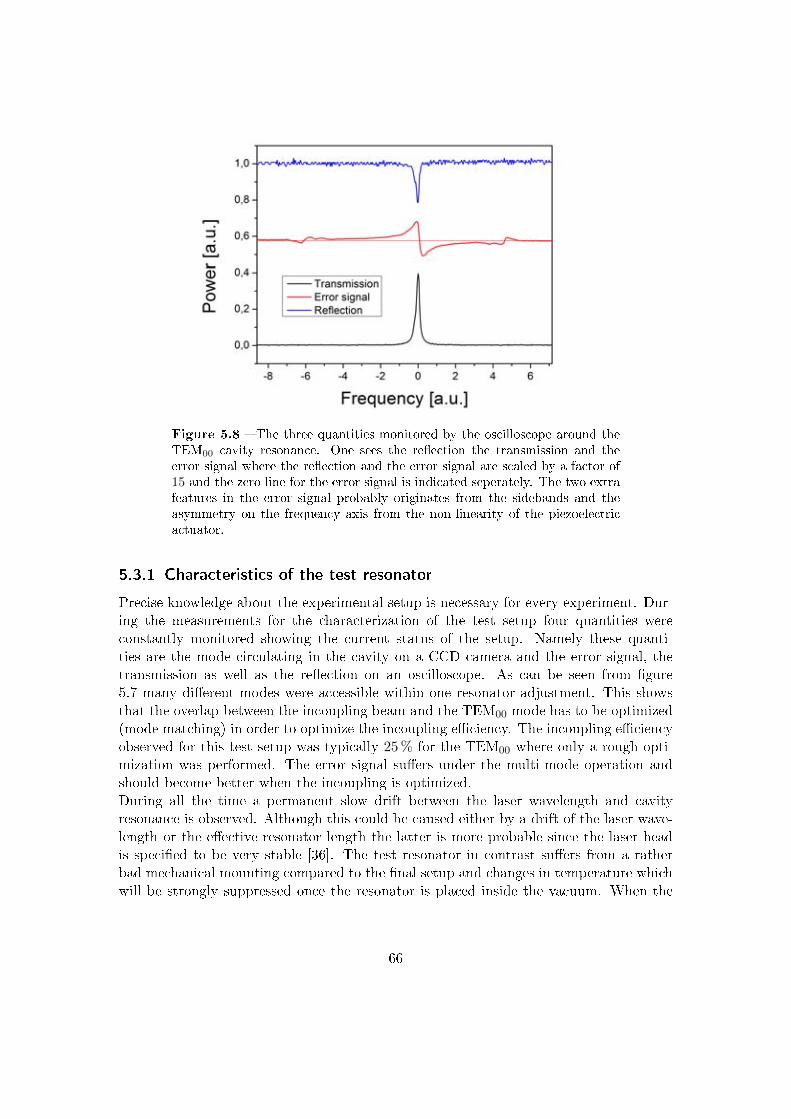
Figure 5.8 The three quantities monitored by the oscilloscope around theTEM00 cavity resonance. One sees the reection the transmission and theerror signal where the reection and the error signal are scaled by a factor of15 and the zero line for the error signal is indicated seperately. The two extrafeatures in the error signal probably originates from the sidebands and theasymmetry on the frequency axis from the non-linearity of the piezoelectricactuator.
5.3.1 Characteristics of the test resonator
Precise knowledge about the experimental setup is necessary for every experiment. Dur-ing the measurements for the characterization of the test setup four quantities wereconstantly monitored showing the current status of the setup. Namely these quanti-ties are the mode circulating in the cavity on a CCD camera and the error signal, thetransmission as well as the reection on an oscilloscope. As can be seen from gure5.7 many dierent modes were accessible within one resonator adjustment. This showsthat the overlap between the incoupling beam and the TEM00 mode has to be optimized(mode matching) in order to optimize the incoupling eciency. The incoupling eciencyobserved for this test setup was typically 25 % for the TEM00 where only a rough opti-mization was performed. The error signal suers under the multi-mode operation andshould become better when the incoupling is optimized.During all the time a permanent slow drift between the laser wavelength and cavityresonance is observed. Although this could be caused either by a drift of the laser wave-length or the eective resonator length the latter is more probable since the laser headis specied to be very stable [36]. The test resonator in contrast suers from a ratherbad mechanical mounting compared to the nal setup and changes in temperature whichwill be strongly suppressed once the resonator is placed inside the vacuum. When the
66

Figure 5.9 Semi logarithmic plot of the power reected from the cavityversus frequency measured with a spectrum analyzer. The center peak equalsthe EOM modulation frequency of 67, 5MHz. A measurement of the servo-bump position (indicated with arrows) yield a speed of the feedback loop ofapproximately 42kHz. The two extra features are not identied.
drift should be a problem in the nal setup nevertheless a temperature lock of the laserhead on the cavity is possible. For now the large deviations from resonance are correctedmanually by changing the temperature of the laser crystal.
5.3.2 Speed of the feedback loop
To achieve an ecient incoupling the laser wavelength has to match the cavity lengthfor all times. Therefore the cavity length and the laser wavelength are locked to eachother by an active feedback loop. The performance of the cooling resonator dependscritically on the performance of the frequency stabilization hence knowledge about theperformance of the feedback loop is desirable. A possibility to measure the speed of afeedback loop for frequency stabilization is outlined in the following and a measurementin the test setup is presented.In an optimal case neither the laser wavelength nor the cavity length changes over time.In this case the light reected from the cavity at the incoupling mirror has a constantamplitude. When monitoring this light with a photodiode and a spectrum analyzerin principle a delta peak at zero should be visible. However, because of the limitedbandwidth of every spectrum analyzer the peak will be broadened. Furthermore in realitya change in the resonator length is inevitable due to vibrations for instance. When thechange of the resonator length is periodical modulated it will lead to a periodic variation
67

Figure 5.10 Representative cavity transmission signals collected for threedierent gain settings at the lock-box. For low gain the errors often exceedthe correction capability and the circulating power drops drastically (left). Foroptimal gain settings the feedback loop eciently damps the deviations fromresonance between laser frequency and resonator length and the variations inthe circulating power are minimized (middle). When the gain is set to highthe feedback loop start oscillating (with approximately 58 kHz) which againdecreases the stability (right).
of the incoupling eciency and consequently to a periodic variation of the amplitude ofthe reected light. At the spectrum analyzer this modulation will show up as a distinctpeak where the position is determined by the periodicity of the length variation. Inrealistic situations deviations between the laser wavelength and the cavity length occurwith every modulation period leading to a noise spectrum at the spectrum analyzer. For atypical cavity the amplitude of this noise is a decreasing function of frequency. An activefeedback loop can be employed to damp the noise which leads again to a single peak atzero in the optimal case. Unfortunately the speed of a realistic feedback loop is limitedso that the feedback loop becomes inecient for high frequencies. Furthermore, for noisewhere the phase between the oscillating deviation and the correction signal approaches180 the noise at the corresponding frequency is enhanced instead of damped. Thisenhancement can be seen at the spectrum analyzer as the so called servo-bump. Thereforethe frequency where the servo-bump is located is a measure for the speed of the feedbackloop.As discussed above the speed of the entire feedback loop can be estimated from thereected light on the entrance of the resonator whilst it is locked. Using a fast photodiodeand a spectrum analyzer the frequency noise spectrum looks like depicted in gure 5.9.The shown maximum is due to the strong noise introduced by the beat between thesidebands and the laser wavelength which has the frequency of the EOM modulation.The other noise is centered around this maximum since both signals are mixed whendetecting the light with a photodiode5. This way a speed of 42 kHz was measured for thefeedback loop in the test setup. Taking into account that only the slow feedback with thepiezoelecric actuator of the laser was implemented so far this is well appropriate. Further
5For a single noise frequencies Ωn and the modulation frequency Ωm this phenomenon is obvious:E = Emcos(Ωmt)e
iωt + Encos(Ωnt)eiωt →
|E|2 = E2mcos
2(Ωmt) + E2ncos
2(Ωnt) + EmEncos((Ωm − Ωn)t) + EmEncos((Ωm + Ωn)t) for realmodulation Em and noise En amplitudes. The shifted noise is expressed in the last two terms.
68
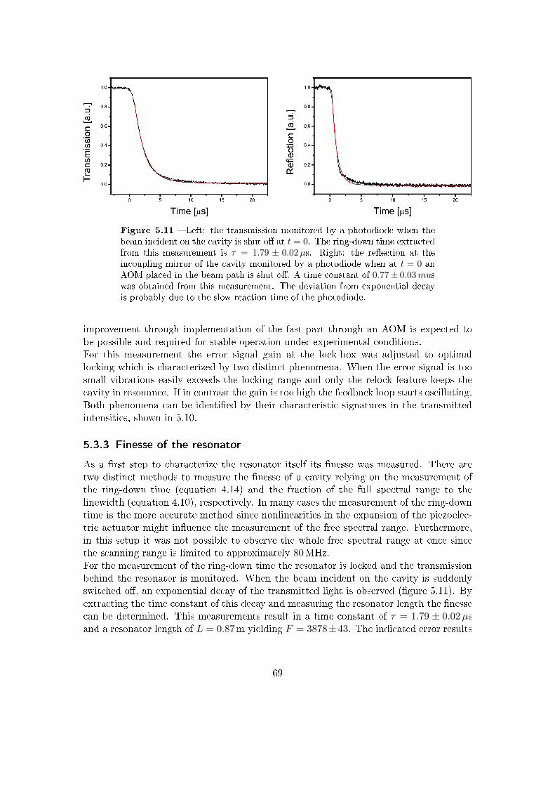
Figure 5.11 Left: the transmission monitored by a photodiode when thebeam incident on the cavity is shut o at t = 0. The ring-down time extractedfrom this measurement is τ = 1.79 ± 0.02µs. Right: the reection at theincoupling mirror of the cavity monitored by a photodiode when at t = 0 anAOM placed in the beam path is shut o. A time constant of 0.77± 0.03muswas obtained from this measurement. The deviation from exponential decayis probably due to the slow reaction time of the photodiode.
improvement through implementation of the fast part through an AOM is expected tobe possible and required for stable operation under experimental conditions.For this measurement the error signal gain at the lock-box was adjusted to optimallocking which is characterized by two distinct phenomena. When the error signal is toosmall vibrations easily exceeds the locking range and only the relock feature keeps thecavity in resonance. If in contrast the gain is too high the feedback loop starts oscillating.Both phenomena can be identied by their characteristic signatures in the transmittedintensities, shown in 5.10.
5.3.3 Finesse of the resonator
As a rst step to characterize the resonator itself its nesse was measured. There aretwo distinct methods to measure the nesse of a cavity relying on the measurement ofthe ring-down time (equation 4.14) and the fraction of the full spectral range to thelinewidth (equation 4.10), respectively. In many cases the measurement of the ring-downtime is the more accurate method since nonlinearities in the expansion of the piezoelec-tric actuator might inuence the measurement of the free spectral range. Furthermore,in this setup it was not possible to observe the whole free spectral range at once sincethe scanning range is limited to approximately 80MHz.For the measurement of the ring-down time the resonator is locked and the transmissionbehind the resonator is monitored. When the beam incident on the cavity is suddenlyswitched o, an exponential decay of the transmitted light is observed (gure 5.11). Byextracting the time constant of this decay and measuring the resonator length the nessecan be determined. This measurements result in a time constant of τ = 1.79 ± 0.02µsand a resonator length of L = 0.87m yielding F = 3878±43. The indicated error results
69
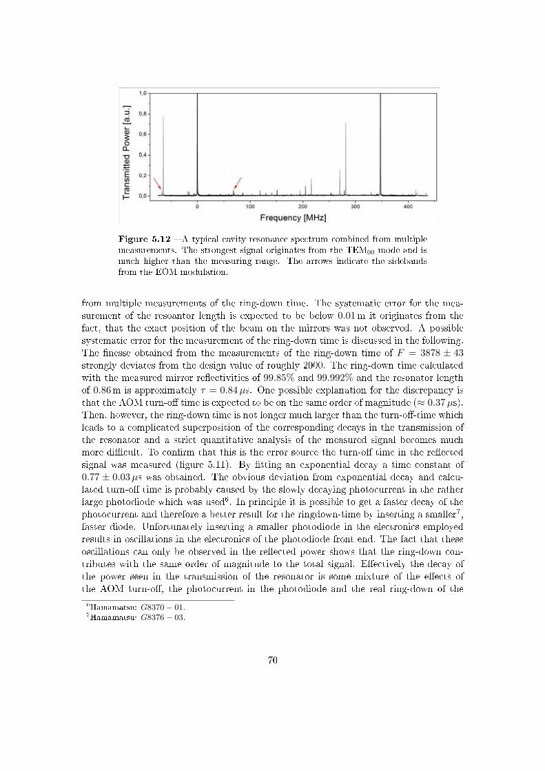
Figure 5.12 A typical cavity resonance spectrum combined from multiplemeasurements. The strongest signal originates from the TEM00 mode and ismuch higher than the measuring range. The arrows indicate the sidebandsfrom the EOM modulation.
from multiple measurements of the ring-down time. The systematic error for the mea-surement of the resoantor length is expected to be below 0.01m it originates from thefact, that the exact position of the beam on the mirrors was not observed. A possiblesystematic error for the measurement of the ring-down time is discussed in the following.The nesse obtained from the measurements of the ring-down time of F = 3878 ± 43strongly deviates from the design value of roughly 2000. The ring-down time calculatedwith the measured mirror reectivities of 99.85% and 99.992% and the resonator lengthof 0.86m is approximately τ = 0.84µs. One possible explanation for the discrepancy isthat the AOM turn-o time is expected to be on the same order of magnitude (≈ 0.37µs).Then, however, the ring-down time is not longer much larger than the turn-o-time whichleads to a complicated superposition of the corresponding decays in the transmission ofthe resonator and a strict quantitative analysis of the measured signal becomes muchmore dicult. To conrm that this is the error source the turn-o time in the reectedsignal was measured (gure 5.11). By tting an exponential decay a time constant of0.77 ± 0.03µs was obtained. The obvious deviation from exponential decay and calcu-lated turn-o time is probably caused by the slowly decaying photocurrent in the ratherlarge photodiode which was used6. In principle it is possible to get a faster decay of thephotocurrent and therefore a better result for the ringdown-time by inserting a smaller7,faster diode. Unfortunately inserting a smaller photodiode in the electronics employedresults in oscillations in the electronics of the photodiode front end. The fact that theseoscillations can only be observed in the reected power shows that the ring-down con-tributes with the same order of magnitude to the total signal. Eectively the decay ofthe power seen in the transmission of the resonator is some mixture of the eects ofthe AOM turn-o, the photocurrent in the photodiode and the real ring-down of the6Hamamatsu: G8370− 01.7Hamamatsu: G8376− 03.
70

Figure 5.13 Typical resonance peak of the TEM00 mode measured witha oscilloscope (black). From the tted Lorentzian curve (red) a line width of∆νl = 83 ± 9 kHz was obtained, where the frequency scale was taken fromgure 5.12 (the experimental settings were not changed between both mea-surements).
resonator. Since they all are on the same order of magnitude a strong error in the nessemeasured this way is expected.To obtain a better result the free spectral range and the line width were measured di-rectly. For determining the nesse one actually only needs to measure the ratio betweenthese quantities so a frequency reference is not necessary. However, the EOM sidebandsoer such a reference allowing for simple measuring of absolute values. In principle thesemeasurements can easily be done by monitoring the transmission behind the resonatorwhile scanning the laser frequency. Unfortunately the piezoelectric tube of the laser headin combination with the given voltage is not able to scan over a full free spectral range.Therefore multiple pictures were taken. The center frequency of the laser is changedbetween those pictures by changing the temperature of the laser crystal manually. Com-bining the single datasets leads to gure 5.12. Here the nonlinearity of the expansion ofthe piezoelectric crystal became obvious. To minimize the eect of this nonlinearity onlya quarter of the possible voltage was applied to the piezoelectric crystal. The remainingerror of this eect was estimated to be approximately ±7 % for the free spectral range.The sidebands can easily be identied by switching on and o the EOM and are marked ingure 5.12. The EOM frequency for these measurements was 68MHz. Figure 5.13 showsthe transmission peak of the TEM00 mode. This peak is tted with a Lorentzian functionto obtain the linewidth. It is essential to keep the settings of the lock-box unchangedbetween both measurements in order to keep the frequency axis comparable. By this
71

method a free spectral range of ∆νf = 347±56MHz and a linewidth of ∆νl = 83±9 kHzwas obtained which results in a nesse of F = 4190 ± 737. Surprisingly this coincideswith the result obtained from the ring-down measurement (within the error-range) im-plying that the measured mirror reectivities contains large errors. Therefore the nesseobtained from the ring-down measurements (F = 3878± 43) is expected to be quite ac-curate. However, the indicated error range originates from multiple measurements of thelinewidth and does not account for systematic errors in the measurement of the resonatorlength or the ring-down time due to the superposition of the three decays.A more realistic value and error range can be derived when the measured linewidth iscombined with the free spectral range calculated from the measured resonator length. Itis expected that the systematic errors due to the nonlinearity of the piezoelectric actu-ator are neglectable for the measurement of the linewidth since here only a very smallscanning range is used. Therefore the error for the linewidth is governed by statisticalerrors and the linewidth is given by: ∆νl = 83± 9 kHz. The error for the measurementof the resonator length is estimated to be less than one centimetre and the length ismeasured to be L = 0.87± 0.01m. With these values the nesse of the resonator can becalculated to be F = 4155 ± 453. The free spectral range and the enhancement can bederived as well they are ∆νf = 345±4MHz and ε = 1323±144 respectively. The designvalue for the enhancement is ε = 633 which implies that the measured enhancement isapproximately twice the design value but since locking was possible and the time fortransport is approximately 0.5 s which is still reasonable no complications are expected.
72

6 Conclusion & outlook
In this diploma thesis a ring resonator for a novel all-optical cooling scheme was designedand tested. Since this resonator will be placed inside the vacuum in order to reduce thelosses and make a high power enhancement possible, the main vacuum chamber was de-signed as well.All quantum gas experiments rely on evaporative cooling to reach temperatures at theNanokelvin scale. The choice of the trapping potential is crucial to realize an ecientevaporation scheme since the trapping potential determines the initial atom number andthe thermalisation rate. The new evaporation scheme employed in this experiment is de-signed to overcome the drawbacks of the dependency on the spin state for magnetic trapsand the small capturing volume for typical deep dipole traps. Two counter-propagatinglaser beams are coupled into a ring resonator and the atoms will be loaded from theMOT into the interference pattern at a large beam diameter outside of the focus of theresonator mode. The atoms will subsequently be transported to the resonator focus andevaporation will be performed in a traveling wave conguration. The transport leadsto an enhanced atom density in the focus which consequently results in an enhancedthermalisation rate. Since no magnetic elds are used for trapping a Feshbach resonancecan be used to further enhance the evaporation eciency.Apart from a small focus which determines the divergence and therefore the beam di-ameter at the MOT position, a high enhancement was the most important goal for theresonator design. In order to reach an enhancement of roughly 600 the resonator will beplaced inside the vacuum which minimizes the losses. The design of the resonator and thevacuum chamber thus have strong impact on each other. Therefore special attention waspaid to construct mirror holders for the cooling resonator which are very compact andenable the possibility to test the whole resonator setup outside of the vacuum chamber.Nevertheless a stable resonator setup was realized. In addition to the cooling resonatorthe chamber geometry is determined by the optical access required and the magnetic coilarrangement for the MOT eld and the Feshbach eld. Optical access is necessary forthe MOT beams, the atomic beam which is either created by a Zeeman slower or by anoptional 2D-MOT, the resonator beams and for imaging as well as for a second dipoletrap which realizes a transport of the atoms from the position where the evaporation isperformed into a glass cell. The option for the 2D-MOT is included to maintain maximalexibility. For the same reason a broadband coating was chosen for the viewports at themain vacuum chamber. The magnetic elds are generated by a single pair of coils whichis situated very close to the position of the atoms in the dipole trap. Since the MOT lieso-center with respect to these coils additional pushing coils are used to shift the MOTeld.The vacuum chamber and the resonator were designed as 3D-models and manufactured
73

in professional workshops. All desired elements have arrived in the lab by now and thevacuum chamber as well as the nal resonator are being assembled. However, when thework in the lab started not all parts of the resonator were produced so that rst mea-surements to characterize the resonator were performed with a test resonator. Moreover,the electronics and optics necessary to stabilise the resonator were also implemented andtested. With this setup the nesse of the resonator was determined to be F = 4155±453,a value that is approximately a factor of two higher than the design value. This discrep-ancy may be explainable with large spatial inhomogenities in the mirror coating process.The design value was chosen relatively low to make the frequency stabilization less chal-langing. However, already in the test setup only a slow frequency stabilization with ameasured bandwidth of 42 kHz was sucient to lock the resonator. Hence we are in thefortuitous position to have a larger power enhancement without signicant drawbacks.As the next step it is planned to test the nal cooling resonator where special attentionwill be paid to the performance of the piezoelectric actuator. Once this slow part of thefeedback loop is shown to perform well the fast part of the feedback loop realized withan AOM will be implemented and tested as well. To complete the setup for the coolingresonator the second beam will be coupled into the resonator and the power control willbe implemented and tested as well. The last task performed in the test setup will bethe optimal adjustment of the resonator mode to TEM00 with a small focus. Afterwardsthe optical and electronic setup will be moved to the main experimental table and theresonator will be inserted into the vacuum chamber. Finally the transfer from the MOT,the transport and the evaporative cooling will be tested and optimized.Parallel to the work at the resonator the other parts of the experimental setup are plannedand assembled. For example the design of the magnetic coils and appropriate holderswas carried out by K. Morgener and the manufacturing is in progress. The oven and theglass cell design are nished as well (by W. Weimer) and the oven is already assembled.At the moment the work in the lab concentrates on the chamber bake-out and resonatortesting as well as on setting up the laser system and optics for the MOT beam prepa-ration. When all this is accomplished and the new experiment is nally set up it willoer a high degree of exibility as well as excellent imaging resolution. Therefore it isexpected that exciting results will be produced and the experiment will contribute to theeld of ultra-cold atoms in the next years.
74

7 Appendix
7.1 Feshbach resonances
Figure 7.1 The s-wave scattering potential for two neutral atoms. Theopen (bottom) and closed (top) channel are characterized by distinct internalstates. Indicated are some vibrational dimer states, the scattering energy εsand the (tunable) channel spacing ∆U . The background scattering length a0is determined by the energy of the highest bound state in channel A.
The term Feshbach resonance originates from nuclear physics where resonance phenom-ena in nuclear reactions can be described by a generalized theory of Herman Feshbach.The most basic expression of Feshbach like phenomena is the Levison theorem whichclaims that a resonant enhancement of the scattering length can be observed whenevera new bound state appears at the dissociation energy of a potential.Nowadays magnetically induced Feshbach resonances are a widely used tool in the eld ofquantum gases. They allow for arbitrary manipulation of the interaction strength whenchanging the magnetic eld hence they enable the investigation of such exiting phe-nomena as fermionic superuidity and quantum magnetism. In the frame of this workFeshbach resonances are important to enhance the eciency of the evaporative cooling.A detailed discussion of Feshbach resonances is out of the scope of this thesis such thatonly a very short qualitative overview will be given. Very comprehensible summaries canbe found in [6] and [21] where this section is based on the latter.
75

Figure 7.2 The qualitative behavior of the scattering length a around a Fes-hbach resonance (bottom) and the corresponding position of a bound state inthe closed channel with respect to the dissociation energy of the open channel(top) are shown. Please note that for positive scattering lengths an accessible(when ramping over the resonance) molecular state evolves.
Figure 7.1 schematically shows the s-wave scattering potential1 of two neutral atoms fortwo dierent internal state congurations (scattering-channels). Those channels may bedened by dierent spin congurations which allow for tuning the energy dierence (∆U)due to the Zeeman eect with a magnetic eld. This of course also changes the positionof the bound states2 in the B channel relative to the dissociation energy of channel A. Ifa bound state of channel B has an energy similar to the scattering energy εs and a cou-pling between both channels is present this state will modify the scattering wavefunctionand hence the scattering length. The inuence of the bound state in B on the scatteringlength depends on its position relative to the dissociation energy of channel A and thuson an externally applied magnetic eld. This oers the possibility to tune the interactionof an atomic gas by adjusting the current in a magnetic coil.The qualitative behavior of the scattering length around a Feshbach resonance (for lowenergies) is shown in gure 7.2. The corresponding formula reads:
a = a0
(1− ∆B
B −Bres
)(7.1)
where ∆B is the region where a has the opposite sign to the background scattering lengtha0. It is determined by the coupling strength between the two channels and ∂
∂B∆U onresonance.To address the Feshbach resonance in a whole atomic ensemble a homogeneous magneticeld is necessary which can be generated by a Helmholtz coil conguration.
1For higher angular momentum the centrifugal barrier has to be taken into account.2They are not really bound since they can spontaneously decay in the continuum of channel A.
76

Figure 7.3 Artistic impression of the glass cell surrounded by two ringcavities and a microscope. A second, identical microscope will be placed abovethe glass cell so that imaging and manipulation of the atoms on the Nanometrescale is simultaneous possible. The resonators will be used to realize dierentdipole potentials where connement in the vertical direction can be added byseparate laser beams.
7.2 The glass cell
The glass cell within the experimental setup can be seen right in front of gure 3.1.The glass cell is surrounded by a stable structure for attachment of magnetic coils whichallows for precise control of the interaction strength in the atomic ensemble. Two mi-croscopes (NA = 0.62) below and above the glass cell allow for both, observation andmanipulation with nearly single site resolution. This high resolution is possible since theglass cell is only 16mm high. The geometry of the glass cell is determined by the beamsplanned to use. As depicted in gure 7.3 two four mirror ring resonators are employed togenerate a crossed dipole trap. The advantage of this resonator design is that very deeptraps can be generated with moderate laser power and additional the beam will have avery stable, clear prole. Another point is that two beams coupled into one resonator willalways perfectly overlap. This can for example be used to generate nearly homogeneouspotentials by coupling in one red and one blue detuned laser. To benet from the highenhancement of the resonators it is important that the glass cell is anti reection coated.For conventional glass cells coating from inside is not possible. However, with a specialbonding technique it is possible to manufacture a glass cell where for the optical accessa coating is applied3. The resonators provide a very elliptical mode and by shining intwo blue detuned beams from the vertical direction under an angle of only 12 we areable to bring a large fraction of the atoms in a two-dimensional system. Of course it isalso possible to generate optical latices by coupling counter propagating beams into theresonators. In addition optical access for three beams at an angle of 120 is foreseenwhich allows for the generation of triangle latices.
3The glass cell is manufactured by the technical glass devision of Precision Glassblowing of Colerado.
77

8 Bibliography
[1] M. Albiez, R. Gati, J. Fölling, S. Hunsmann, M. Cristiani, and M. K.
Oberthaler, Direct observation of tunneling and nonlinear self-trapping in a singlebosonic josephson junction, Physical Review Letters, 95 (2005), p. 010402.
[2] M. Anderson, J. Ensher, M. Matthews, C. Wieman, and E. Cornell,Observation of Bose-Einstein Condensation in a Dilute Atomic Vapor, Science, 269(1995), pp. 198201.
[3] M. Bartenstein, A. Altmeyer, S. Riedl, R. Geursen, S. Jochim, C. Chin,J. Hecker Denschlag, and R. Grimm, Precise determination of 6li cold colli-
sion parameters by radio-frequency spectroscopy on weakly bound molecules, PhysicalReview Letters, 94 (2005), p. 103201.
[4] E. D. Black, An introduction to Pound-Drever-Hall laser frequency stabilization,American Journal of Physics, 69 (2001), pp. 7987.
[5] S. Chiesa, C. N. Varney, M. Rigol, and R. T. Scalettar, Magnetism
and Pairing of Two-Dimensional Trapped Fermions, Physical Review Letters, 106(2011), p. 035301.
[6] C. Chin, R. Grimm, P. Julienne, and E. Tiesinga, Feshbach resonances in
ultracold gases, Reviews of Modern Physics, 82 (2010), p. 12251286.
[7] B. DeMarco and D. S. Jin, Onset of Fermi Degeneracy in a Trapped Atomic
Gas, Science, 285 (1999), pp. 17031706.
[8] M. Eckstein, M. Kollar, and P. Werner, Thermalization after an Interaction
Quench in the Hubbard Model, Physical Review Letters, 103 (2009), p. 056403.
[9] S. Giorgini, L. P. Pitaevskii, and S. Stringari, Theory of ultracold atomic
Fermi gases, Reviews of Modern Physics, 80 (2008), p. 12151274.
[10] R. Grimm, M. Weidemüller, and Y. B. Ovchinnikov, Optical Dipole Traps
for Neutral Atoms, Advances In Atomic, Molecular, and Optical Physics, 42 (2000),pp. 95170.
[11] K. Günter, T. Stöferle, H. Moritz, M. Köhl, and T. Esslinger, Bose-fermi mixtures in a three-dimensional optical lattice, Physical Review Letters, 96(2006), p. 180402.
78

[12] P. C. Hobbs, Photodiode Front Ends: The Real Story, Optics and Photonics News,12 (2001), pp. 4447.
[13] P. C. D. Hobbs, Building electro-optical systems, John Wiley & Sons, 2008.
[14] S. Hong, S. Y.H., and K. J.T., Residual gas survey of stainless steel 304 extremehigh vacuum chamber with hot cathode ionization gauge, Measurement, 41 (2008),pp. 10261031.
[15] P. Horowitz and W. Hill, The art of electronics, Cambridge University Press,2 ed., 1989.
[16] J. Hubbard, Electron Correlations in Narrow Energy Bands, Proceedings of theRoyal Society of London. Series A, Mathematical and Physical Sciences, 276, No.1365 (1963), pp. 238257.
[17] M. Inguscio, W. Ketterle, and C. Salomon, Ultra-cold Fermi Gases, in Pro-ceedings of the International School of Physics "Enrico Fermi", 2008.
[18] D. Jaksch, C. Bruder, J. I. Cirac, C. W. Gardiner, and P. Zoller, Coldbosonic atoms in optical lattices, Physical Review Letters, 81 (1998), pp. 31083111.
[19] W. Ketterle and M. W. Zwierlein, Making, probing and understanding ultra-
cold fermi gases, arXiv:0801.2500, (2008).
[20] P. A. Lee, N. Nagaosa, and X.-G. Wen, Doping a Mott insulator: physics of
hightemperature superconductivity, Reviews of Modern Physics, 78 (2006), pp. 1785.
[21] A. Marte, Feshbach-Resonanzen bei Stößen ultrakalter Rubidiumatome, PhD the-sis, Technische Universität München, 2003.
[22] H. J. Metcalf and P. van der Straten, Laser Cooling and Trapping, Springer,1999.
[23] A. Mosk, S. Jochim, H. Moritz, T. Elsässer, M. Weidemüller, and
R. Grimm, Resonator-enhanced optical dipole trap for fermionic lithium atoms,Optics Letters, 26 (2001), pp. 18371839.
[24] R. Mottl, A bowtie resonator trap to load, transport and cool fermionic atoms,master's thesis, ETH Zürich, 2009.
[25] J. F. O'Hanlon, A User's Guide to Vacuum Technology, John Wiley & Sons, 2003.
[26] C. Ospelkaus, S. Ospelkaus, L. Humbert, P. Ernst, K. Sengstock, andK. Bongs, Ultracold heteronuclear molecules in a 3d optical lattice, Physical ReviewLetters, 97 (2006), p. 120402.
[27] C. Pethick and H. Smith, Bose-Einstein Condensation in Dilute Gases, Cam-bridge University Press, 2 ed., 2008.
79

[28] A. Polkovnikov, K. Sengupta, A. Silva, and M. Vengalattore, Nonequi-librium dynamics of closed interacting quantum systems, arXiv:1007.5331v1, (2010).
[29] A. Prodromides, Non-Evaporable Getter Thin Film Coatings for Vacuum Appli-
cations, PhD thesis, Ecole Polytechnique Federale de Lausanne, 2002.
[30] Product catalogue, The Vacuum Technology Book, Pfeier Vacuum GmbH,2008.
[31] J. Sakurai, Modern Quantum Mechanics, Addison-Wesley Publishing Company,1994.
[32] T. Schnider, Design of a Second Generation Optical Lattice Experiment for an
Ultra-Cold 40K Quantum Gas, master's thesis, ETH Zürich, 2009.
[33] A. E. Siegman, Lasers, University Science Books, 1986.
[34] O. Svelto, Principles of Lasers, Springer, 2010.
[35] U. Tietze, C. Schenk, and E. Gamm, Halbleiter-Schaltungstechnik, Springer,13 ed., 2010.
[36] User's Manual, Mephisto MOPA Product Line, Innolight, Version 2.1.
[37] W. Weimer, Stabilizing a Diode Laser on a Narrow Linewidth Ring Cavity, mas-ter's thesis, ETH Zürich, 2010.
[38] Wikipedia, Pressure measurement Wikipedia, The Free Encyclopedia, 2011. [On-line; accessed 18-April-2011].
[39] Wikipedia, Sagittalebene (Optik) Wikipedia, The Free Encyclopedia, 2011. [On-line; accessed 21-April-2011].
[40] B. Zimmermann, T. Müller, J. Meineke, T. Esslinger, and H. Moritz,High-resolution imaging of ultracold fermions in microscopically tailored optical po-
tentials, New Journal of Physics, 13 (2011), p. 043007.
80

9 Acknowledgement
First of all I would like to thank Prof. Dr. H. Moritz for giving me the opportunity tocontribute to the new experiment with this diploma thesis and for his support whenevera problem arose. It was a very exiting and instructive experience to see the new groupand the experiment growing.Special thanks are due also to Prof. Dr. K. Sengstock who is the second advisor for thisthesis. He was the one to get me enthusiastic about the research eld of quantum gasesdue to his motivating lectures and his talent to transfer his own fascination to others.I would like to thank each member of the research group for his support and the enjoyableatmosphere in the oce and the lab, apart from the bobbery produced byW.W. of course.I had a great time working with you.Without the help of the administrative and technical sta at the institute and in thephysics workshop this diploma thesis would not be possible. Therefore I would like tothank Ellen Gloy, Reinhard Mielck and Ralf Lühr as well as Stephan Fleig and ThomasMarckmann for the invaluable support they gave me.Very special thanks to my teachers W. Falkenberg and G. Mücke who engaged my interestfor sciences in school and believed in me when others already gave up. I know that youare a main reason why it was possible that I could follow my interests and study physics.I would like to thank my fellow students as well since they constantly encourage me tolearn and learn and learn... Apart from the time at the university I will always rememberthe countless nights in the student dorms, at the Reeperbahn or just at home with oneto twelve bottles of beer. Here Damian Böcker is to mention by name who, I think I cansay that, is my best fellow student and a really good friend.Of course I do not forget about my friends from da big city who helped me very activelywhen it came to drinking and barbecue. Especially Joschka Böddeling is to mention sincehe tried to improve my englisch in this diploma thesis unsuccessfully.For my loved girlfriend I have a thousand kisses instead of a single thank you. She madethe past years the most happiest of my life and dragged me to the real life whenever Idespaired on physical problems. Kocham ci¦ mój chomiczku!Last but not least I would like to express my deep gratefulness to my parents. Theysupported me throughout my whole education and nally learned to exercise patiencewhen my learning process took a little longer.
81