Real-Time Systems Chapter 1 Hermann Kopetz. Real-Time-Systems, Kluwer 1997.

3
Real-time TTCN for testing real-time and multimedia systems
Thomas Walter Swiss Federal Institute of Technology Zurich, Computer Engineering and Networks Laboratory (TIK) CH-8092 Zurich, Switzerland, Tel: +41-1-632 7007, Fax: +41-1-632 1035, e-mail: [email protected]
lens Grabowski Medical University of Liibeck, Institute for Telematics Ratzeburger Allee 160, D-23538 Liibeck, Germany, Tel: +49-451-5003723, Fax: +49-451-5003722, e-mail: [email protected]
Abstract In this paper we define real-time TTCN and apply it to several applications. In realtime TTCN, statements are annotated with time labels that specify their earliest and latest execution times. The syntactical extensions of TTCN are the definition of a table for the specification of time names and time units, and two new columns in the dynamic behaviour description tables for the annotation of statements with time labels. We define an operational semantics for real-time TTCN by mapping realtime TTCN to timed transition systems. Alternatively, we introduce a refined TTCN snapshot semantics that takes time annotations into account.
Keywords Conformance testing, TTCN, test cases, real-time testing
Testing of Communicating Systems, M. Kim, S. Kang & K. Hong (Eds) Published by Chapman & HaIl © 1997 IFIP
38 Pan Two TTCN Extensions
1 INTRODUCTION
Testing, or to be precise conformance testing, is the generally applied process in validating communication software. A conformance testing methodology and framework (IS09646-1 1994) have been established within the standardization bodies of ISO and lTU. An essential part of this methodology is a notation, called TTCN (Tree and Tabular Combined Notation) (IS09646-3 1996), for the definition of conformance test cases. TTCN has been designed for testing systems for which in general timing between communicating entities has not been an issue. Test cases are specified as sequences of test events which are input and output events of abstract service primitives (ASP) or protocol data units (PDU). The relative ordering of test events is defined in a test case behaviour description.
The situation is changing now. We can identify two main new kinds of distributed systems: firstly, real-time systems which stem from the use of computers for controlling physical devices and processes. For these systems, real-time communication is essential for their correct behaviour. Secondly, multimedia systems which involve the transmission of several continuous streams (of bits) and their timely reproduction (e.g., synchronization of audio and video). However, as pointed out in, e.g., (Ates et al. 1996), TTCN is not an appropriate test notation for testing real-time and multimedia systems: Firstly, test events in TTCN are for message-based systems and not for stream-based systems. Secondly, in TTCN real-time can only be approximated. In this paper we define a real-time extension of TTCN as a contribution for solving the second problem.
Our extension of TTCN to real-time TTCN is on a syntactical and a semantical level. The syntactical extension is that we allow an annotation of test events with an earliest execution time (EET) and a latest execution time (LET). Informally, a test event may be executed if it has been enabled for at least E ET units and it must be executed if it has been enabled for LET units. For the definition of an operational semantics of real-time TTCN we use timed transition systems (Henzinger et al. 1991).
A number of techniques for the specification of real-time constraints have been proposed which are besides others: time Petri Nets (Berthmieu et al. 1991, Merlin et al. 1976) and extensions of LOTOS (Bowman et al. 1994, Hogrefe et al. 1992, Leonard et al. 1994, Quemada et al. 1987), SDL (Hogrefe et al. 1992, Leue 1995) and ESTELLE (Fischer 1996). As in the cited literature, our approach allows the timing of actions relative to the occurrence of previous actions. The difference between the cited approaches and ours is that real-time TTCN is a hybrid method used for the specification of properties of test systems and requirements on implementations under test (lUT).
Section 2 gives a brief introduction to TTCN. Section 3 explains real-time TTCN. The applicability of our approach is shown in Section 4. Section 5 concludes the paper with an assessment of our work and the discussion of open issues.
Real-time ITCN for testing real-time and multimedia system 39
2 TTCN - TREE AND TABULAR COMBINED NOTATION
TTCN is a notation for the description of test cases to be used in conformance testing. For the purpose of this paper we restrict our attention to TTCN concepts related to the description of the dynamic test case behaviour. Further details on TTCN can be found in: (Baumgarten and Giessler 1994, Baumgarten and Gattung 1996, IS09646-3 1996, Kristoffersen et al. 1996, Linn 1989, Probert et al. 1992, Sarikaya 1989).
2.1 Abstract testing methods and TTCN
A test case specifies which outputs from an IUT can be observed and which inputs to an IUT can be controlled. Inputs and outputs are either abstract service primitives (ASPs) or protocol data units (PDUs). In general, several concurrently running distributed test components (TC) participate in the execution of a test case. TCs are interconnected by coordination points (CPs) through which they asynchronously exchange coordination messages (CMs). TCs and IUT logically communicate by exchanging PDUs which are embedded in ASPs exchanged at points of control and observation (PCOs), which are interfaces above and below the IUT. Since in most cases the lower boundary of an IUT does not provide adequate PCO interfaces, TCs and JUT communicate by using services of an underlying service provider.
2.2 Test case dynamic behaviour descriptions
The behaviour description of a TC consists of statements and verdict assignments. A verdict assignment is a statement of either PASS, FAIL or INCONCLUSIVE, concerning the conformance of an IUT with respect to the sequence of events which has been performed. TTCN statements are test events (SEND, IMPLICIT SEND, RECEIVE, OTHERWISE, TIMEOUT and DONE), constructs (CREATE, ATTACH, ACTIVATE, RETURN, GOTO and REPEAT) and pseudo events (qualifiers, timer operations and assignments).
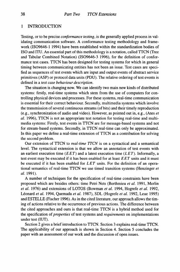
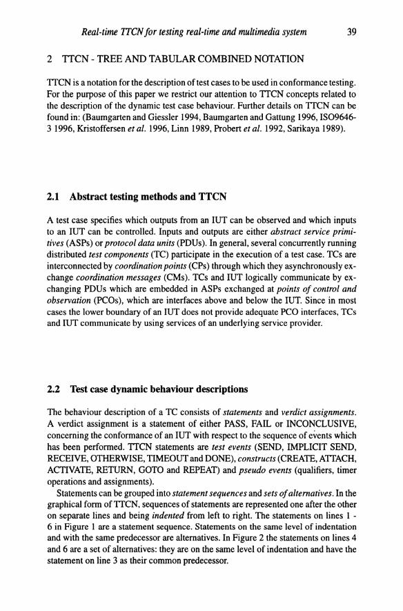
Statements can be grouped into statement sequences and sets of alternatives. In the graphical form of TTCN, sequences of statements are represented one after the other on separate lines and being indented from left to right. The statements on lines 1 -6 in Figure 1 are a statement sequence. Statements on the same level of indentation and with the same predecessor are alternatives. In Figure 2 the statements on lines 4 and 6 are a set of alternatives: they are on the same level of indentation and have the statement on line 3 as their common predecessor.
40 Part Two ITCN Extensions
Test Case Dynamic Behaviour Nr Label Behaviour Description CRef V Comments 1 CP?CM connected RECEIVE 2 (NumOfSends := 0) Assignment 3 REPEAT SendData Construct
UNTIL [NumOfSends > MAX] 4 START Timer Timer Operation 5 ?TIMEOUT timer TIMEOUT 6 L ! N-DATA request data SEND
Figure 1 TICN Behaviour Description - Sequence of Statements.
Test Case Dynamic Behaviour Nr Label Behaviour Description CRef V Comments 1 [TRUE] Qualifier 2 Ll (NumOfSends := NumOfSends + 1) 3 +SendData ATTACH 4 [NOT NumOfSends > MAX] Alternative I 5 -> Ll GOTO 6 [NumOfSends > MAX] Alternative 2
Figure 2 TICN Behaviour Description - Set of Alternatives.
2.3 Test component execution
A TC starts execution of a behaviour description with the first level of indentation (line 1 in Figure 1), and proceeds towards the last level of indentation (line 6 in Figure 1). Only one alternative out of a set of alternatives at the current level of indentation is executed, and test case execution proceeds with the next level of indentation relative to the executed alternative. For example, in Figure 2 the statements on line 4 and line 6 are alternatives. If the statement on line 4 is executed, processing continues with the statement on line 5. Execution of a behaviour description stops if the last level of indentation has been visited, a test verdict has been assigned, or a test case error has occurred.
Before a set of alternatives is evaluated, a snapshot is taken (IS09646-31996), i.e., the state of the TC and the state of all PCOs, CPs and expired timer lists related to the TC are updated and frozen until the set of alternatives has been evaluated. This guarantees that evaluation of a set of alternatives is an atomic and deterministic action.
Alternatives are evaluated in sequence, and the first alternative which is evaluated successfully (i.e., all conditions of that alternative are fulfilled (IS09646-3 1996» is executed. Execution then proceeds with the set of alternatives on the next level of indentation. If no alternative can be evaluated successfully, a new snapshot is taken and evaluation of the set of alternatives is started again.

Real-time ITCN for testing real-time and multimedia system 41
3 REAL-TIME TTCN
In real-time TICN, statements are annotated with time labels for earliest and latest execution times. Execution of a real-time TICN statement is instantaneous. The syntactical extensions of TICN (Section 3.2) are the definition of a table for the specification of time names and time units and the addition of two columns for the annotation of TICN statements in the behaviour description tables. We define an operational semantics for real-time TICN (Section 3.3). For this we define a mapping of real-time TICN to timed transition systems (Hen zinger et al. 1991) which are introduced in Section 3.1. Applying timed transition systems has been motivated by our experiences with the definition of an operational semantics for TICN (Walter et al. 1992, Walter and Plattner 1992). To emphasize the similarities of TICN and real-time TICN we also propose a refined snapshot semantics which takes time annotations into account and which is compliant with the timed transition system based semantics. In the following section we quote the main definitions of (Henzinger et al. 1991).
3.1 Timed transition systems
A transition system (Keller 1976) consists of a set V of variables, a set ~ of states, a subset e s; ~ of initial states and a finite set T of transitions which also includes the idle transition t/. Every transition t E T is a binary relation over states; i.e., it defines for every state s E ~ a possibly empty sett(s) S;; L of so-called t-successors. A transition t is said to be enabled on state s if and only if t(s) i= 0. For the idle transition t/ we have that t[ = {(s, s) Is E ~}.
An infinite sequence a = SOSI ... is a computation of the underlying transition system if So E e is an initial state, and for all i ~ 0 there exists atE T such
that Si+l E t(Si), denoted Si ~ Si+l, i.e., transition t is taken at position i of computation a.
The extension of transition systems to timed transition systems is that we assume the existence of a real-valued global clock and that a system performs actions which either advance time or change a state (Henzinger et al. 1991). Actions are executed instantaneously, i.e., they have no duration.
A timed transition system consists of an underlying transition system and, for each transition t E T, an earliest execution time E E Tt E 1N and a latest execution time LETt E 1N U {oo} is defined. * We assume that E E Tt ~ LETt and, wherever they are not explicitly defined, we presume the default values are zero for EETt and 00
for LETt. EETt and LETt define timing constraints which ensure that transitions cannot be performed neither to early (EETt) nor too late (LETt).
A timed state sequence p = (a, T) consists of an infinite sequence a of states and
*In principle, time labels may not only be natural numbers. For an in-depth discussion of alternative domains for time labels, the reader is referred to (Alur et al. 1996).

42 Part Two ITCN Extensions
an infinite sequence T of times Tj e Rand T satisfies the following two conditions:
• Monotonicity: Vi ::: 0 either 11+1 = Tj or 11+1 > Tj 1\ Si+1 = Sj.
• Progress: Vt e 1R 3 i ::: 0 such that 11 ::: t.
Monotonicity implies that time never decreases but possibly increases by any amount between two neighbouring states which are identical. If time increases this is called a time step. The transition being performed in a time step is the idle transition which is always enabled (see above). The progress condition states that time never converges, i.e., since R has no maximal element every timed state sequence has infinitely many time steps. Summarizing, in timed state sequences state activities are interleaved with time activities. Throughout state activities time does not change, and throughout time steps the state does not change.
A timed state sequence p = (0', T) is a computation of a timed transition system if and only if state sequence 0' is a computation of the underlying transition system and for every transition t e 7 the following requirements are satisfied:
• for every transition t e 7 and position j ::: 0 if t is taken at j then there exists a position i, i ::: j such that Tj + E ET, ::: Tj and t is enabled on Sj, Si+ I, ... , S j-I
and is not taken at any of the positions i, i + 1, ... , j - 1, i.e., a transition must be continuously enabled for at least EETt time units before the transition can be taken.
• for every transition t e 7 and position i ::: 0, if t is enabled at position i, there exists a position j, i ::: j, such that 1'; + LET, ::: Tj and either t is not enabled at j or t is taken at j, i.e., a transition must be taken if the transition has been continuously enabled for LET, time units.
A finite timed state sequence is made infinite by adding an infinite sequence of idle transitions or time activities.
3.2 Syntax of real-time TTCN
In real-time TICN, timing information is added in the declarations and the dynamic part of a test suite.
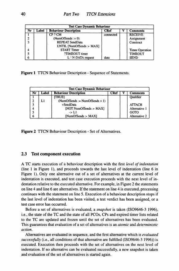
As shown in Figure 3 the specification of time names, time values and units is done in an Execution Time Declarations table. Apart from the headings the table looks much like the TICN Timer Declarations table. Time names are declared in the Time Name column. Their values and the corresponding time units are specified on the same line in the Value and Unit columns. The declaration of time values and time units is optional.
Real-time ITCN for testing real-time and multimedia system 43
Execution Time Declarations Time Name Value Unit Comments BET 1 s BET value LET 1 min LET value WFN 5 ms Wait For Nothing NoDur min No specified value
Figure 3 Execution Time Declarations Table.
EET and LET* are predefined time names with default values zero and infinity. Default time values can be overwritten (Figure 3).
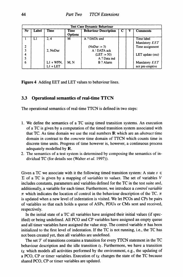
Besides the static declarations of time values in an Execution Time Declarations table, changing these values within a behaviour description table can be done by means of assignments (Figure 4). However, evaluation of time labels should alway result in E ET and LET values for which 0 ::: E ET ::: LET holds. As indicated in Figure 4 we add a Time and a Time Options column to Test Case Dynamic Behaviour tables (and similar for Default Dynamic Behaviour and Test Step Dynamic Behaviour tables). An entry in the Time column specifies EET and LET for the corresponding TTCN statement. Entries may be constants (e.g., line 1 in Figure 4), time names (e.g., the use of NoDur on line 3), and expressions (e.g., line 6).
In general, EET and LET values are interpreted relative to the enabling time of alternatives at a level of indentation, i.e., the time when the level of indentation is visited the first time. However, some applications may require to define EET and LET values relative to the execution of an earlier test event, i.e, not restricted just to the previous one. In support of this requirement, a label in the Label column may not only be used in a GOTO but can also be used in the Time column, so that EET and LET values are computed relative to the execution time of the alternative identified by the label: In Figure 4 on line 6 the time labels (Ll + WFN, Ll + LET) are referring to the execution time of the alternative in line 1 (for which label Ll is defined).
Entries in the Time Options column are combinations of symbols M and N. Similar to using labels in expressions, time option N allows to express time valbes relative to the alternative's own enabli~g time even though some TTCN statements being executed in between two successive visits of the same level of indentation. Thus, the amount of time needed to execute the sequence of TTCN statements in between two successive visits is compensated: If time option N is defined, then execution of this alternative is not pre-emptive with respect to the timing of all alternatives at the same level of indentation.
In some executions of a test case, a RECEIVE or OTHERWISE event may be evaluated successfully before it has been enabled for E ET units. If it is intended to define E ET as a mandatory lower bound when an alternative may be evaluated successfully, then time option M has to be specified. Informally, if time option M is specified and the corresponding alternative can be successfully evaluated before it has been enabled for E ET units, then this results in a FAIL verdict.
·We use different font types for distinguishing between syntax, BET and LET, and semantics, EET and LET.
44 Part Two ITCN Extensions
Test Case Dynamic Behaviour Nr Label Time Time Behaviour Description C V Comments
Options I Ll 2,4 M A ? DATA und Time label
Mandatory EET 2 (NoDur:= 3) Time assignment 3 2, NoDur A !DATAack 4 (LET:= 50) LET update (ms) 5 A? Dataind 6 Ll +WFN, M,N B? Alarm Mandatory E E T
Ll + LET not pre-emptive
Figure 4 Adding BET and LET values to behaviour lines.
3.3 Operational semantics of real-time TTCN
The operational semantics of real-time TTCN is defined in two steps:
1. We define the semantics of a TC using timed transition systems. An execution of a TC is given by a computation of the timed transition system associated with that TC. As time domain we use the real numbers R which are an abstract time domain in contrast to the concrete time domain of TTCN which counts time in discrete time units. Progress of time however is, however, a continuous process adequately modelled by R.
2. The semantics of a test system is determined by composing the semantics of individual TC (for details see (Walter et al. 1997)}.
Given a TC we associate with it the following timed transition system: A state s E
:E of a TC is given by a mapping of variables to values. The set of variables V includes constants, parameters and variables defined for the TC in the test suite and, additionally, a variable for each timer. Furthermore, we introduce a control variable 7r which indicates the location of control in the behaviour description of the TC. 7r
is updated when a new level of indentation is visited. We let PeOs and CPs be pairs of variables so diat each holds a queue of ASPs, PDUs or CMs sent and received, respectively.
In the initial state of a TC all variables have assigned their initial values (if specified) or being undefined. All PCO and CP variables have assigned an empty queue and all timer variables have assigned the value stop. The control variable 7r has been initialized to the first level of indentation. If the TC is not running, i.e., the TC has not been created yet, then all variables are undefined.
The set 'T of transitions contains a transition for every TTCN statement in the TC behaviour description and the idle transition tl. Furthermore, we have a transition tE which models all activities performed by the environment, e.g., the updating of a PeO, CP or timer variables. Execution of tE changes the state of the TC because shared PeO, CP or timer variables are updated.
Real-time ITeN for testing real-time and multimedia system 45
In the following we assume that the current level of indentation has been expanded as defined in Annex B of (IS09646-3 1996). After expansion its general form is Al[eexPl, lexpI1, ... , An [eexPn, lexPn], where Ai denotes an alternative and eeXPi, lexPi are expressions for determining EET and LET values of alternative Ai. The evaluation of expressions eeXPi and lexPi depends on whether eeXPi and lexPi make use of a label Ln. If so, absolute time references are converted into time references relative to the enabling time of the current set of alternatives.
Let eval be a function from time expressions to time values for E ET or LET. Let enablingTime(Ai) be a function that returns the time when alternative Ai has been enabled. Let executionTime(Ln) be a function that returns the execution time of an alternative at the level of indentation identified by label Ln. Function NOW returns the current global time. Notice that for all alternatives Ai in a set of alternatives, enablingTime(Ai) is the same. Since only one alternative of a set of alternatives is executed, executionTime(Ln) returns the execution time of the executed alternative. For the evaluation of time expressions the following rules apply:
1. If eeXPi and lexPi do not involve any operator Ln then EET = eval(eexPi) and LET = eval(lexPi). It is required that 0::: EET ::: LET holds; otherwise test case execution should terminate with a test case error indication.
2. If eeXPi and lexPi involve any operator Ln then, firstly, executionTime(Ln) is substituted for Ln in eeXPi and lexPi resulting in expressions eexp~ or lexp~, and secondly, EET = eval(eexp~) - NOW and LET = eval(lexp;) - NOW. It is required that 0 ::: EET ::: LET holds; otherwise test case execution should terminate with a test case error indication.
We say that alternative Ai is potentially enabled if Ai is in the current set of alternatives. Ai is enabled if Ai is evaluated successfully (Section 2.3), Ai is executable if Ai is enabled and Ai has been potentially enabled for at least E ET; and at most LET; time units.
We make the evaluation of a TC explicit by defining the following refined snapshot semantics (cf. Section 2.3).
1. The TC is put into its initial state. 2. A snapshot is taken, i.e., PCO, CP and timer variables are updated and frozen.
(a) If the level of indentation is reached from a preceding alternative (i.e., not by a GOTO or RETURN) then all alternatives are marked potentially enabled and the global time is taken and stored. The stored time is accessible by function enablingTime( Ai).
(b) If the level of indentation is reached by executing a GOTO or RETURN and enabling-Time(Ai) has been frozen (see Step 5. below) then all alternatives are marked potentially enabled but enablingTime(Ai) is not updated.
(c) If the level of indentation is reached by executing a GOTO or RETURN but enablingTime(Ai) has not been frozen previously then all alternatives are mar-
46 Part Two TTCN Extensions
ked potentially enabled and the global time is taken and stored. The stored time is accessible by function enablingTime(Aj).
(d) Otherwise, it is a new iteration of Steps 2. - 5.
EET and LET are computed as described above. If for an Aj enablingTime(Aj) + LET; < NOW then test case execution stops (FAIL verdict).
3. All alternatives which can be evaluated successfully are marked enabled. If no alternative in the set of alternatives can be evaluated successfully then processing continues with Step 2. If for an enabled alternative, say A;, time option M is set and if enablingTime(A;)+ E E T; > NOW then test case execution stops with a FAIL verdict.
4. An enabled alternative A; is marked executable provided that enablingTime(A;)+ EET; ::: NOW::: enablingTime(A;) + LET; and if there is another enabled alternative A) with enablingTime(A) + EET) ::: NOW::: enablingTime(A) + LET), then i < j, i.e., the i-th alternative precedes the j-th alternative in the set of alternatives. If no alternative can be marked executable then processing continues with Step 2.
5. The alternative A; marked executable in Step 4. is executed. If a label Ln is specified then the alternative's execution time is stored and which can be accessed by function executionTime(Ln). If time option N is specified for the executed alternative, enablingTime(A;) is frozen for later use. Control variable 1T is assigned the next level of indentation. Test case execution terminates if the last level of indentation has been reached or a final test verdict has been assigned; otherwise, evaluation continues with Step 2.
Remarks: If any potentially enabled alternative cannot be evaluated successfully before latest execution time then a specified real-time constraint has not been met and test case execution stops. Conversely, if an alternative can be evaluated successfully before it has been potentially enabled for E ET (Step 3.) then a defined real-time constraints is violated, too, and test case terminates with an error indication. In Step 4., the selection of alternatives for execution from the set of enabled alternatives follows the same rules as in TTCN (IS09646-3 1996). If a TC stops (Step 5.) then the finite timed state sequence is extended to an infinite sequence by adding an infinite sequence of idle transitions. Every iteration of Steps 2. - 5. is assumed to be atomic.
In terms of the definitions given in Section 3.1, a computation of a TC is a timed state sequence p = (a, T). By substituting potentially enabled for enabled and executed for taken, the refined snapshot semantics can be stated formally as:
1. If alternative A is executed at position j of p then there exists positions i and I, i ::: I ::: j, such that T; + E E T ::: Tj and enablingTime( A) = T; and alternative A is evaluated successfully on all states SI, SI+I, ... , S )-1 and is not executed at any position I, I + 1, ... , j - 1; i.e., alternative A is potentially enabled for at least

Real-time ITCN for testing real-time and multimedia system 47
Test Case Dynamic Behaviour Nr Label Time Time Options Behaviour Description CRef V C I LI 2.4 M PCOI ? N-DATA ind info 2 ... 3 -> Ll 4 O. INFINITY PC02 ? N-ABORT ind abort 5 ...
Figure 5 Partial Real-Time ITCN Behaviour Description.
E ET time units before it is executed provided it can be evaluated successfully after having been potentially enabled, and
2. for position i ~ 0, if enablingTime(A) = T; then for position j, i ::s j, T; + LET ~ Tj and alternative A is not evaluated successfully on any state Sf, ... , Sj or A is executed at j provided no other alternative A' exists for which these conditions hold and which precedes A in the set of alternatives; i.e., the first alternative evaluated successfully is executed at latest LET units after being potentially enabled.
Example 1 In ISDN (Integrated Digital Services Network) systems (Halsall 1994, Tanenbaum 1989), the B channels are used by applications for data exchange whereas the D channel is used for the management of connections between users or application processes. We consider a scenario where an ISDN connection between test system and IUT has been established and where PCO 1 and PC02 are the respective Band D channel interfaces. At the B channels we expect to receive user data every E ETI = 2 to LETI = 4 time units. At any time the ISDN connection may be aborted on the D channel.
We consider the partial real-time ITCN behaviour description given in Figure 5. The first alternative may be evaluated successfully and may be executed only in the interval EETI = 2 and LETI = 4 because time option M is set on line 1. Let us assume that at T' with enablingTime(AI) + EETI ::s T' ::s enablingTime(AI) + LETI, an N-DATA indication is received. The first alternative may be executed at Til with enablingTime(AI) + EETI .::s T' ::s Til ::s enablingTime(AI) + LETI (Step 4.) because no other alternative is executable (no N-ABORT indication has been received yet). A corresponding computation might be:
... ~ (s, enablingTime(AI» ..!.!... (s, T') ~ (s', T') ..!.!... (s', Til) ~ (S", Til) ~ ...
The reception of an N-DATA indication at time T' is a state activity, (s, T') ~ (s', T'), because a PCO variable is updated by the environment performing transition tEo Transitions t] are time activities, and transition tl is the transition that is derived from ITCN statement line 1.
Suppose that an N-DATA indication and an N-ABORT indication have been received from the environment at some Till : T' ::s Till ::s Til. Then, although both

48 Part Two ITCN Extensions
alternatives are executable, the first alternative is executed because of the ordering of alternatives in the set of alternatives (Step 4.). If an N-DATA indication is received at T < enablingTime(Aj) + EET! then test case execution stops with a FAIL verdict (Step 3.).
If no N-DATA indication and no N-ABORT indication have been received before LET! time units after the alternatives have been potentially enabled, test case execution stops with a FAIL verdict (Step 2.).
3.4 Discussion of the proposal
If we assume that no time values are defined (in this case E ET and LET are zero and infinity, respectively), execution of a test case results in the same sequence of statetransitions as in TTCN. Therefore, our definition of real-time TTCN is compatible to TTCN (IS09646-3 1996, Baumgarten and Gattung 1996).
Real-time TTCN combines property and requirement oriented specification styles. Time labels for TTCN statements, in general, define real-time constraints for the test system. A test system should be implemented so that it can comply with all properties defined. Time labels for RECEIVE and OTHERWISE events, which imply a communication with the IUT, define requirements on the IUT and the underlying service provider. As well as the test system, the underlying service provider is assumed to be "sufficiently reliable for control and observation to take place remotely" (IS09646-11994). For real-time TTCN, the underlying service provider should also be sufficiently fast with respect to the timing of activities. Therefore, if a timing constraint of a RECEIVE or OTHERWISE event is violated, this clearly is an indication ·that the IUT is faulty and the test run should end with a FAIL verdict assignment.
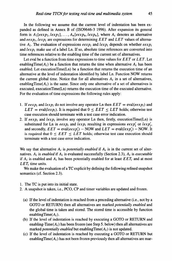
In Figure 6, a test case in TTCN is given for the one in Example 1. The timing constraints on the reception of N-DATA indications are expressed using timers T1 and T2. The alternatives coded on lines 2 and 8 in combination check that an NDATA indication should not be received before EET (= timer T1); otherwise, test case execution results in a FAIL verdict (line 8). The TIMEOUT event on line 6 controls the latest execution time and if timer T2 expires then this gives a FAIL verdict.
Let us assume that test case execution is at the third level of indentation (lines 3, 5 and 6) and that TIMEOUT of timer T2 precedes reception of an N-DATA indication. Furthermore, let us assume that the system executing the test case is heavily loaded and therefore evaluation of a set of alternatives lasts too long, so that both events are included in the same snapshot. The late arrival of an N-DATA indication gets undetected because of the ordering of alternatives on line 3, 5 and 6. A fast system will take a snapshot which includes the TIMEOUT only whereas a slow system will take a snapshot which includes an N-DATA indication and a TIMEOUT. For the slow system, the RECEIVE succeeds over the TIMEOUT event. Unfortunately, the behaviour description does not comply with the requirement stated in (IS09646-
Real-time ITCN for testing real-time and multimedia system 49
Test Case Dynamic Behaviour Nr Label Behaviour Description CRef V C I L1 START Tl(EET) 2 ?TIMEOUT Tl START T2(LET-EET) 3 PCOl ? N-DATA indication data 4 -> L1 5 PC02 ? N-ABORT indication STOP T2 abort INCONC 6 ?TIMEOUTT2 FAIL 7 PC02 ? N-ABORT indication STOP Tl abort INCONC 8 PCOl ? OTHERWISE STOP Tl FAIL
Figure 6 TTCN Behaviour Description for Example 1.
1 1994) "that the relative speed of the systems executing the test case should not have an impact on the test result" and thus is not valid.
In conclusion, real-time TTCN is more powerful than TTCN. The advantage of real-time TTCN is that all requirements on the behaviour of test systems and IUT are made explicit. The timing constraints that are to be met and thus the result of a test case is determined by the observed behaviour only.
4 APPLICATION OF REAL-TIME TTCN
In this section we continue the discussion of real-time TTCN by elaborating on an example taken from high speed networking.
In ATM (Asynchronous Transfer Mode) networks (Black 1995, Prycker 1995), network traffic control is performed to protect network and users to achieve predefined network performance objectives. During connection set up a traffic contract specification is negotiated and agreed between users and network. A contract specification consists of the connection traffic descriptor, given in peak cell rate and cell delay variation tolerance; the requested quality-of-service class, given in terms of required cell loss ratio, cell transfer delay and cell delay variation; and the definition of a compliant connection.
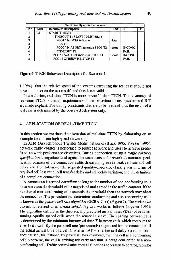
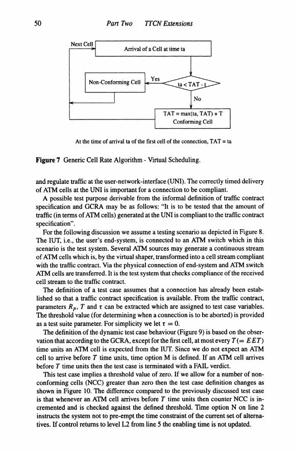
A connection is termed compliant as long as the number of non-conforming cells does not exceed a threshold value negotiated and agreed in the traffic contract. If the number of non-conforming cells exceeds the threshold then the network may abort the connection. The procedure that determines conforming and non-conforming cells is known as the generic cell rate algorithm (GCRA(T,r» (Figure 7). The variant we discuss is referred to as virtual scheduling and works as follows (Prycker 1995): The algorithm calculates the theoretically predicted arrival times (TAT) of cells assuming equally spaced cells when the source is active. The spacing between cells is determined by the minimum interarrival time T between cells which computes to T = 1/ R p with R p the peak cell rate (per seconds) negotiated for the connection. If the actual arrival time of a cell ta is after TAT - r, r the cell delay variation tolerance caused, for instance, by physical layer overhead, then the cell is a conforming cell; otherwise, the cell is arriving too early and thus is being considered as a nonconforming cell. Traffic control subsumes all functions necessary to control, monitor
50 Part Two rrCN Extensions
Next Cell Arrival of a Cell at time ta
Yes Non-Confonning Cell 1+---<::::
TAT = max(ta, TAT) + T Confonning Cell
At the time of arrival ta of the first cell of the connection, TAT = ta
Figure 7 Generic Cell Rate Algorithm - Virtual Scheduling.
and regulate traffic at the user-network-interface (UNI). The correctly timed delivery of ATM cells at the UNI is important for a connection to be compliant.
A possible test purpose derivable from the informal definition of traffic contract specification and GCRA may be as follows: "It is to be tested that the amount of traffic (in terms of ATM cells) generated at the UNI is compliant to the traffic contract specification" .
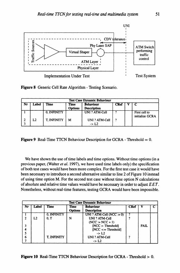
For the following discussion we assume a testing scenario as depicted in Figure 8. The IUT, i.e., the user's end-system, is connected to an ATM switch which in this scenario is the test system. Several ATM sources may generate a continuous stream of ATM cells which is, by the virtual shaper, transformed into a cell stream compliant with the traffic contract. Via the physical connection of end-system and ATM switch ATM cells are transferred. It is the test system that checks compliance of the received cell stream to the traffic contract.
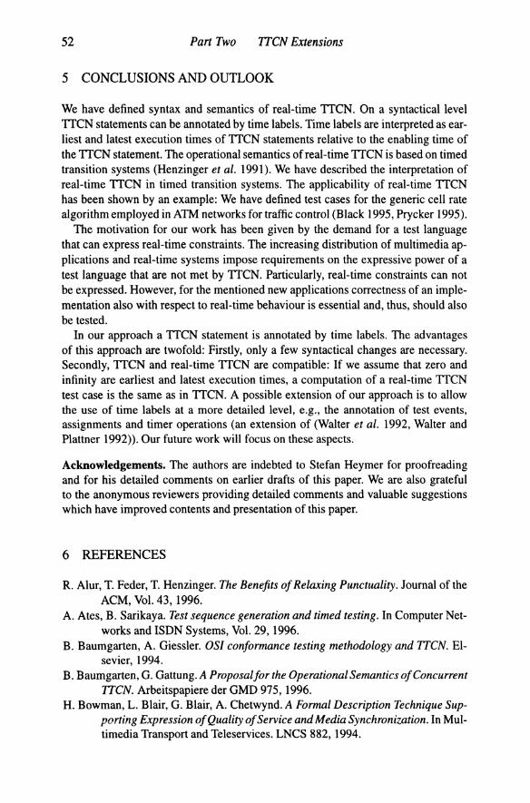
The definition of a test case assumes that a connection has already been established so that a traffic contract specification is available. From the traffic contract, parameters Rp, T and T can be extracted which are assigned to test case variables. The threshold value (for determining when a connection is to be aborted) is provided as a test suite parameter. For simplicity we let T = O.
The definition of the dynamic test case behaviour (Figure 9) is based on the observation that according to the GCRA, except for the first cell, at most every T (= E ET) time units an ATM cell is expected from the IUT. Since we do not expect an ATM cell to arrive before T time units, time option M is defined. If an ATM cell arrives before T time units then the test case is terminated with a FAIL verdict.
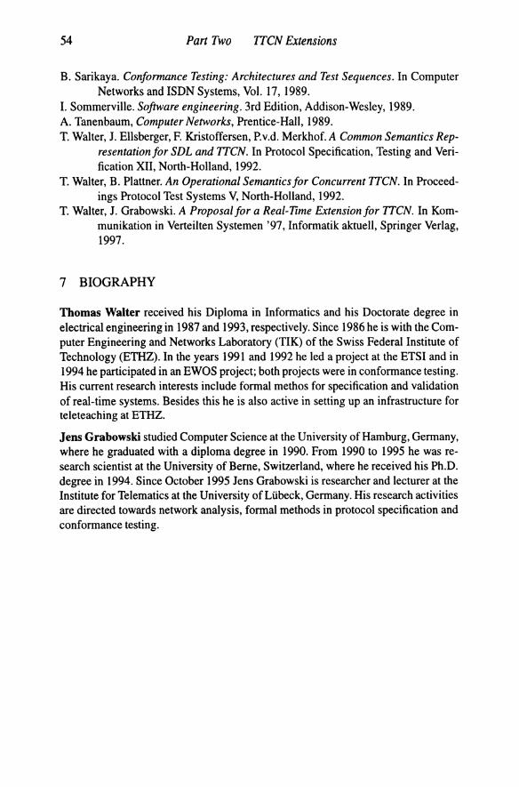
This test case implies a threshold value of zero. If we allow for a number of nonconforming cells (NCC) greater than zero then the test case definition changes as shown in Figure 10. The difference compared to the previously discussed test case is that whenever an ATM cell arrives before T time units then counter NCC is incremented and is checked against the defined threshold. Time option N on line 2 instructs the system not to pre-empt the time constraint of the current set of alternatives. If control returns to level L2 from line 5 the enabling time is not updated.
Real-time TfCN for testing real-time and multimedia system 51
UNI I
I CDV t lerancel
Phy Laser SAP ~-----,
Virtual Shaper
Physical Layer
Implementation Under Test
ATMSwitch performing
traffic control
Test System
Figure 8 Generic Cell Rate Algorithm - Testing Scenario.
Test Case Dynamic Behaviour Nr Label Time Time Behaviour CRef V C
Options Description I 0, INFINITY UNI ? ATM-Cell ? First cell to
initialize GCRA 2 L2 T,INFINITY M UNI ? ATM-Cell ? 3 -> L2
Figure 9 Real-Time TTCN Behaviour Description for GCRA - Threshold = O.
We have shown the use of time labels and time options. Without time options (in a previous paper, (Walter et al. 1997), we have used time labels only) the specification of both test cases would have been more complex. For the first test case it would have been necessary to introduce a second alternative similar to line 2 of Figure 10 instead of using time option M. For the second test case without time option N calculations of absolute and relative time values would have be necessary in order to adjust EET. Nonetheless, without real-time features, testing GCRA would have been impossible.
Test Case Dynamic Behaviour Nr Label Time Time Behaviour CRef V C
Options Description I 0, INFINITY UNI ? ATM-Cell (NCC := 0) ? 2 L2 0, T N UNI ? ATM-Cell ?
(NCC:= NCC + I) 3 [NCC > Threshold) FAIL 4 [NCC <= Threshold) 5 -> L2 6 T, INFINITY UNI ? ATM-Cell ? 7 -> L2
Figure 10 Real-Time TTCN Behaviour Description for GCRA - Threshold> O.
52 Pan Two ITCN Extensions
5 CONCLUSIONS AND OUTLOOK
We have defined syntax and semantics of real-time TICN. On a syntactical level TICN statements can be annotated by time labels. Time labels are interpreted as earliest and latest execution times of TICN statements relative to the enabling time of the TICN statement. The operational semantics of real-time TICN is based on timed transition systems (Hen zinger et al. 1991). We have described the interpretation of real-time TICN in timed transition systems. The applicability of real-time TTCN has been shown by an example: We have defined test cases for the generic cell rate algorithm employed in ATM networks for traffic control (Black 1995, Prycker 1995).
The motivation for our work has been given by the demand for a test language that can express real-time constraints. The increasing distribution of multimedia applications and real-time systems impose requirements on the expressive power of a test language that are not met by TTCN. Particularly, real-time constraints can not be expressed. However, for the mentioned new applications correctness of an implementation also with respect to real-time behaviour is essential and, thus, should also be tested.
In our approach a TTCN statement is annotated by time labels. The advantages of this approach are twofold: Firstly, only a few syntactical changes are necessary. Secondly, TICN and real-time TTCN are compatible: If we assume that zero and infinity are earliest and latest execution times, a computation of a real-time TTCN test case is the same as in TTCN. A possible extension of our approach is to allow the use of time labels at a more detailed level, e.g., the annotation of test events, assignments and timer operations (an extension of (Walter et al. 1992, Walter and Plattner 1992». Our future work will focus on these aspects.
Acknowledgements. The authors are indebted to Stefan Heymer for proofreading and for his detailed comments on earlier drafts of this paper. We are also grateful to the anonymous reviewers providing detailed comments and valuable suggestions which have improved contents and presentation of this paper.
6 REFERENCES
R. Alur, T. Feder, T. Henzinger. The Benefits of Relaxing Punctuality. Journal of the ACM, Vol. 43, 1996.
A. Ates, B. Sarikaya. Test sequence generation and timed testing. In Computer Networks and ISDN Systems, Vol. 29,1996.
B. Baumgarten, A. Giessler. OS] conformance testing methodology and ITCN. Elsevier, 1994.
B. Baumgarten, G. Gattung. A Proposalfor the Operational Semantics of Concurrent ITCN. Arbeitspapiere der GMD 975,1996.
H. Bowman, L. Blair, G. Blair, A. Chetwynd. A Formal Description Technique Supporting Expression of Quality of Service and Media Synchronization. In Multimedia Transport and Teleservices. LNCS 882, 1994.

Real-time ITCN for testing real-time and multimedia system 53
B. Berthomieu, M. Diaz. Modeling and Verification of Time Dependent Systems Using Time Petri Nets. In IEEE Transactions on Software Engineering, Vol. 17, No.3, March 1991.
U. Black. ATM - foundationfor broadband networks. Prentice-Hall, 1995. A. Danthine, Y. Baguette, G. Leduc, Leonard. The OSI95 Connection-Mode Trans
port Service - The Enhanced QoS. In High Performance Networking, IFIP, 1992.
S. Fischer. Implementation of multimedia systems based on a real-time extension of Estelle. In Formal Description Techniques IX Theory, application and tools, 1996.
F. Halsall, Data Communications, Computer Networks and Open Systems, AddisonWesley, 1994.
D. Hogrefe, S. Leue. Specifying Real-Time Requirementsfor Communication Protocols. Technical Report lAM 92-015, University of Berne, 1992.
T. Henzinger, Z. Manna, A. Pnueli. Timed Transition Systems. In Real-Time: Theory in Practice. LNCS 600, 1991.
ISOIIEC. Information Technology - OSI - Conformance Testing Methodology and Framework - Part I: General Concepts. ISOIIEC IS 9646-1, 1994.
ISOIIEC. Information Technology - OSI - Conformance Testing Methodology and Framework - Part 2: Abstract Test Suite Specification. ISOIIEC IS 9646-2, 1994.
ISOIIEC. Information Technology - OSI - Conformance Testing Methodology and Framework - Part 3: The Tree and Tabular Combined Notation (1TCN). ISOIIEC IS 9646-3,1996.
R. Keller. Formal Verification of Parallel Programs. In Communications of the ACM, Vol. 19, No.7, 1976.
F. Kristoffersen, T. Waiter. ITCN: Towards a formal semantics and validation of test suites. In Computer Network and ISDN Systems, Vol. 29,1996.
L. Leonard, G. Leduc. An Enhanced Version of Timed LOTOS and its Application to a Case Study. In Formal Description Techniques VI, North-Holland, 1994.
S. Leue. Specifying Real-Time Requirements for SDL Specifications - A Temporal Logic Based Approach. In Protocol Specification, Testing and Verification XV, 1995.
R. Linn. Conformance Evaluation Methodology and Protocol Testing. In IEEE Journal on Selected Areas in Communications, Vol. 7, No.7, 1989.
P. Merlin, D. Faber. Recoverability of Communication Protocols. In IEEE Transactions on Communication, Vol. 24, No.9, September 1976.
M. Prycker. Asynchronous transfer mode: solutions for broadband ISDN, 3rd Edition, Prentice Hall, 1995.
R. Probert, o. Monkewich. 1TCN: The International Notation for Specifying Tests of Communications Systems. In Computer Networks and ISDN Systems, Vol. 23,1992.
J. Quemada, A. Fernandez. Introduction of Quantitative Relative Time into LOTOS. In Protocol Specification, Testing and Verification VII, North-Holland, 1987.
54 Part Two ITCN Extensions
B. Sarikaya. Conformance Testing: Architectures and Test Sequences. In Computer Networks and ISDN Systems, Vol. 17, 1989.
I. Sommerville. Software engineering. 3rd Edition, Addison-Wesley, 1989. A. Tanenbaum, Computer Networks, Prentice-Hall, 1989. T. Walter, 1. Ellsberger, F. Kristoffersen, P.v.d. Merkhof. A Common Semantics Rep
resentation for SDL and ITCN. In Protocol Specification, Testing and Verification XII, North-Holland, 1992.
T. Walter, B. Plattner. An Operational Semantics for Concurrent TTCN. In Proceedings Protocol Test Systems V, North-Holland, 1992.
T. Walter, 1. Grabowski. A Proposal for a Real-TIme Extension for ITCN. In Kommunikation in Verteilten Systemen '97, Informatik aktuell, Springer Verlag, 1997.
7 BIOGRAPHY
Thomas Walter received his Diploma in Informatics and his Doctorate degree in electrical engineering in 1987 and 1993, respectively. Since 1986 he is with the Computer Engineering and Networks Laboratory (TIK) of the Swiss Federal Institute of Technology (ETHZ). In the years 1991 and 1992 he led a project at the ETSI and in 1994 he participated in an EWOS project; both projects were in conformance testing. His current research interests include formal methos for specification and validation of real-time systems. Besides this he is also active in setting up an infrastructure for teleteaching at ETHZ.
Jens Grabowski studied Computer Science at the University of Hamburg, Germany, where he graduated with a diploma degree in 1990. From 1990 to 1995 he was research scientist at the University of Berne, Switzerland, where he received his Ph.D. degree in 1994. Since October 1995 Jens Grabowski is researcher and lecturer at the Institute for Telematics at the University of Lubeck, Germany. His research activities are directed towards network analysis, formal methods in protocol specification and conformance testing.