READ ALL INSTRUCTIONS COMPLETELY BEFORE … · 7 FJQCVR Fiber Cleaver Tool 8 FGLSSafety Glasses...
23
© Panduit Corp. 2015 For Technical Support: www.panduit.com/resources/install_maintain.asp INSTALLATION INSTRUCTIONS FS014B Page 1 of 23 Duplex Clip Dust Cap Connector Body 900μm Buffered Boot Backbone ITEM PART NUMBER DESCRIPTION 1 OCTT OptiCam Termination Tool 2 FLCC LC Cradle for OptiCam Termination Tool (OCTT) 3 FVFLPC-1.25SMY 1.25mm Universal Patch Cord for OptiCam Termination Tool (OCTT) 4 CST-115 Fiber Cable Jacket Stripper 5 FALC Alcohol Bottle (empty) 6 FBFSP Fiber Buffer Stripper 7 FJQCVR Fiber Cleaver Tool 8 FGLS Safety Glasses 9 FKS Fiber Kevlar Shears 10 FSTY Fiber Safety Tab Stickers for fiber scraps 11 FSWB-C Cleaning Swabs 12 FWP-C Lint-Free Wipes 13 PFX-0 Fine-Tip Marking Pen 14 -- Isopropyl Alcohol (Reagent Grade, 90% minimum concentration; not available from Panduit) OPTIONAL FS115** LC OptiCam Connector Stripping Template OPTIONAL FJQCVRB Replacement Blade for Fiber Cleaver Keyed LC OptiCam Simplex Connector Part Numbers ‡ and Configurations Table 2 Key Type - Backbone Color B - Red C - Green D - Yellow E - Orange F - Dark Blue Multimode Part Numbers FLCSMC^BRD FLCSMC^CGR FLCSMC^DYL FLCSMC^EOR FLCSMC^FDB Singlemode Part Numbers FLCSSCBRD FLCSSCCGR FLCSSCDYL FLCSSCEOR FLCSSCFDB ‡ For duplex connectors, replace the first S in the part number (FLCSSCABL) with a D (FLCDSCABL). ^Substitute for multimode fiber type: 6 = 62.5/125μm OM1, 5 = 50/125μm OM2, or X = 10Gig 50/125μm OM3. FLCSMC^ABL FLCSSCABL Multimode Part Numbers FLCSMC^HAQ FLCSMC^JRO FLCSMC^KIG FLCSMC^LLB FLCSMC^PWT Singlemode Part Numbers FLCSSCHAQ FLCSSCJRO FLCSSCKIG FLCSSCLLB FLCSSCPWT FLCSMC^GVL FLCSSCGVL A - Black Key Type - Backbone Color H - Aqua J - Rose K - Slate L - Brown P - White G - Violet Multimode Part Numbers FLCSMC^RLV FLCSMC^SPE FLCSMC^TSB FLCSMC^VMA FLCSMC^WMI Singlemode Part Numbers FLCSSCRLV FLCSSCSPE FLCSSCTSB FLCSSCVMA FLCSSCWMI FLCSMC^QCG FLCSSCQCG Key Type - Backbone Color R - Lavender S - Peach T - Steel Blue V - Maroon W - Mint Q - Charcoal ITEMS REQUIRED FOR TERMINATION DUPLEX SIMPLEX FLCSMCXAQY FLCDMCXAQY FLCSMC5BLY FLCSMC6BLY FLCDMC5BLY FLCDMC6BLY Jacketed Boots Available Separately 3.0mm Boot FMCBT3AQ-X FMCBT3BL-X FSCBT3BU-X 1.6 - 2.0mm Boot FMCBT2AQ-X FMCBT2BL-X FSCBT2BU-X FLCSSCBUY FLCDSCBUY CONNECTOR ASSEMBLY Fiber Type Table 1 Standard LC OptiCam Connectors* Backbone Color Aqua Black Electric Ivory Blue 10Gig 50μm 50μm 62.5μm Singlemode *Part numbers shown above Boot Color Aqua Black Black Blue LC OptiCam Fiber Optic Connectors Part Numbers: FLCSMCXAQY, FLCDMCXAQY, FLCSMC5BLY, FLCSSCBUY, FLCDMC5BLY, FLCSMC6BLY, FLCDMC6BLY, FLCDSCBUY Keyed Part Numbers: SEE TABLE BELOW COMPONENT IDENTIFICATION READ ALL INSTRUCTIONS COMPLETELY BEFORE PROCEEDING **Denotes revision letter.
Transcript of READ ALL INSTRUCTIONS COMPLETELY BEFORE … · 7 FJQCVR Fiber Cleaver Tool 8 FGLSSafety Glasses...

© Panduit Corp. 2015
For Technical Support: www.panduit.com/resources/install_maintain.asp
INSTALLATION INSTRUCTIONS FS014B
Page 1 of 23
Duplex Clip
Dust Cap
Connector Body900µm Buffered Boot
Backbone
ITEM PART NUMBER DESCRIPTION
1 OCTT OptiCam Termination Tool2 FLCC LC Cradle for OptiCam Termination Tool (OCTT)3 FVFLPC-1.25SMY 1.25mm Universal Patch Cord for OptiCam Termination Tool (OCTT)4 CST-115 Fiber Cable Jacket Stripper5 FALC Alcohol Bottle (empty)6 FBFSP Fiber Buffer Stripper7 FJQCVR Fiber Cleaver Tool8 FGLS Safety Glasses9 FKS Fiber Kevlar Shears10 FSTY Fiber Safety Tab Stickers for fiber scraps11 FSWB-C Cleaning Swabs12 FWP-C Lint-Free Wipes13 PFX-0 Fine-Tip Marking Pen14 -- Isopropyl Alcohol (Reagent Grade, 90% minimum concentration; not available from Panduit)
OPTIONAL FS115** LC OptiCam Connector Stripping Template OPTIONAL FJQCVRB Replacement Blade for Fiber Cleaver
Keyed LC OptiCam Simplex Connector Part Numbers‡ and Configurations Table 2
Key Type - Backbone Color B - Red C - Green D - Yellow E - Orange F - Dark BlueMultimode Part Numbers FLCSMC^BRD FLCSMC^CGR FLCSMC^DYL FLCSMC^EOR FLCSMC^FDB
Singlemode Part Numbers FLCSSCBRD FLCSSCCGR FLCSSCDYL FLCSSCEOR FLCSSCFDB
‡For duplex connectors, replace the first S in the part number (FLCSSCABL) with a D (FLCDSCABL).^Substitute for multimode fiber type: 6 = 62.5/125µm OM1, 5 = 50/125µm OM2, or X = 10Gig 50/125µm OM3.
FLCSMC^ABLFLCSSCABL
Multimode Part Numbers FLCSMC^HAQ FLCSMC^JRO FLCSMC^KIG FLCSMC^LLB FLCSMC^PWTSinglemode Part Numbers FLCSSCHAQ FLCSSCJRO FLCSSCKIG FLCSSCLLB FLCSSCPWT
FLCSMC^GVLFLCSSCGVL
A - Black
Key Type - Backbone Color H - Aqua J - Rose K - Slate L - Brown P - WhiteG - Violet
Multimode Part Numbers FLCSMC^RLV FLCSMC^SPE FLCSMC^TSB FLCSMC^VMA FLCSMC^WMISinglemode Part Numbers FLCSSCRLV FLCSSCSPE FLCSSCTSB FLCSSCVMA FLCSSCWMI
FLCSMC^QCGFLCSSCQCG
Key Type - Backbone Color R - Lavender S - Peach T - Steel Blue V - Maroon W - MintQ - Charcoal
ITEMS REQUIRED FOR TERMINATION
DUPLEX
SIMPLEXFLCSMCXAQY
FLCDMCXAQY
FLCSMC5BLYFLCSMC6BLY
FLCDMC5BLYFLCDMC6BLY
Jacketed BootsAvailable Separately
3.0mm BootFMCBT3AQ-XFMCBT3BL-XFSCBT3BU-X
1.6 - 2.0mm BootFMCBT2AQ-XFMCBT2BL-XFSCBT2BU-X
FLCSSCBUY
FLCDSCBUY
CONNECTOR ASSEMBLY
Fiber Type
Table 1
Standard LC OptiCam Connectors*
Backbone Color
Aqua
Black
Electric Ivory
Blue
10Gig 50µm
50µm
62.5µm
Singlemode
*Part numbers shown above
BootColor
Aqua
Black
Black
Blue
LC OptiCam Fiber Optic Connectors
Part Numbers: FLCSMCXAQY, FLCDMCXAQY, FLCSMC5BLY, FLCSSCBUY, FLCDMC5BLY, FLCSMC6BLY, FLCDMC6BLY, FLCDSCBUY
Keyed Part Numbers: SEE TABLE BELOW
COMPONENT IDENTIFICATIONREAD ALL INSTRUCTIONS COMPLETELY BEFORE PROCEEDING
**Denotes revision letter.

For Technical Support: www.panduit.com/resources/install_maintain.asp
INSTALLATION INSTRUCTIONS © Panduit Corp. 2015 FS014B
Page 2 of 23
OptiCam Termination Tool Patch Cord MaintenanceClean both ends of the FVFLPC-1.25SMY after 50 matings or sooner if performance diminishes.1. Clean ST connector ferrule endface with a lint-free wipe (FWP-C) soaked with alcohol (reagent grade isopropyl alcohol,
with a minimum 90% concentration).2. Clean ferrule adapter end by unscrewing housing and removing split sleeve. Clean the ferrule endface with an alcohol
soaked lint-free wipe. Refer to Visual Inspection and Cleaning of Fiber Optic Components Best Practices document FS061* at www.panduit.com. Make sure that the split sleeve is clean. Replace the split sleeve onto ferrule and screw housing into place securely.NOTE: Replace the split sleeves if the FVFLPC-1.25SMY continues to have diminished performance after three cleanings. Additional split sleeves for the FVFLPC-1.25SMY are located in the FVFLPC-1.25SMY package.
SAFETY PRECAUTIONS1. SAFETY GLASSES
WARNING: IT IS STRONGLY RECOMMENDED THAT SAFETY GLASSES BE WORN WHEN HANDLING BARE OPTICAL FIBER. THE BARE FIBER IS VERY SHARP AND CAN EASILY DAMAGE THE EYE.
2. ISOPROPYL ALCOHOLWARNING: ISOPROPYL ALCOHOL IS FLAMMABLE. CONTACT WITH THE ALCOHOL CAN CAUSE IRRITATION TO THE EYES. IN CASE OF CONTACT WITH THE EYES, FLUSH WITH WATER FOR AT LEAST 15 MINUTES. ALWAYS USE ISOPROPYL ALCOHOL WITH PROPER LEVELS OF VENTILATION. IN CASE OF INGESTION, CONSULT A PHYSICIAN IMMEDIATELY.
3. DISPOSAL OF BARE FIBERSWARNING: PICK UP AND DISCARD ALL PIECES OF BARE FIBER WITH STICKY TABS. DO NOT LET CUT PIECES OF FIBER STICK TO CLOTHING OR DROP IN THE WORK AREA WHERE THEY ARE HARD TO SEE AND CAN CAUSE INJURY.
4. LASER LIGHT DO NOT VIEW DIRECTLY WITH OPTICAL INSTRUMENTS. CLASS 1M LASER PRODUCT. VIEWING THE LASER OUTPUT WITH CERTAIN OPTICAL INSTRUMENTS (FOR EXAMPLE, EYE LOUPES, MAGNIFIERS, AND MICROSCOPES) WITHIN A DISTANCE OF 100 MM MAY POSE AN EYE HAZARD.CAUTION: USE OF CONTROLS OR ADJUSTMENTS OR PERFORMANCE OF PROCEDURES OTHER THAN THOSE SPECIFIED HEREIN MAY RESULT IN HAZARDOUS RADIATION EXPOSURE.
• NEVER POINT THE LASER INTO THE EYES OF OTHERS.• DO NOT STARE DIRECTLY AT THE LASER BEAM.• DO NOT SET UP TOOL TO WORK AT EYE LEVEL OR OPERATE THE TOOL ON A
REFLECTIVE SURFACE AS THE LASER COULD BE PROJECTED INTO YOUR EYES OR THE EYES OF OTHERS.
ALWAYS TURN THE LASER OFF WHEN IT IS NOT IN USE OR IS LEFT UNATTENDED FOR A PERIOD OF TIME. REMOVE THE BATTERIES WHEN STORING FOR AN EXTENDED PERIOD OF TIME TO AVOID DAMAGE TO THE TOOL SHOULD THE BATTERIES DETERIORATE.
5. CABLE HANDLING WARNING: FIBER OPTIC CABLE CAN BE DAMAGED BY EXCESSIVE PULLING, TWISTING, CRUSHING OR BENDING STRESSES. CONSULT THE APPROPRIATE SPECIFICATION SHEETS AS PROVIDED BY YOUR CABLE VENDOR. ANY DAMAGE MAY DECREASE OPTICAL PERFORMANCE.
TABLE OF CONTENTS Page(s)Safety Precautions and OptiCam Termination Tool Patch Cord Maintenance 2250µm Coated Fiber Termination Instructions with Build-up Tube 3-7250µm Coated Fiber Termination Instructions using Opticom Fanout Kit 8-13900µm Tight-Buffered Fiber Termination Instructions 14-18Jacketed Cable Termination Instructions 19-23
* Denotes revision letter.
Complies with FDA performance standards for laser products except
for deviations pursuant to Laser Notice No. 50, dated June 24, 2007.
Complies with IEC 60825-1Ed. 2 (2007)

For Technical Support: www.panduit.com/resources/install_maintain.asp
INSTALLATION INSTRUCTIONS © Panduit Corp. 2015 FS014B
Page 3 of 23
250µm Coated Fiber Termination with Build-up Tube
To Ensure Best Termination:
• If installing more then a few connectors, or if installing OptiCam connectors for the first time or a long time, terminate several connectors and test immediately after to ensure proper technique is being applied. Testing after a few connectors allows verification that the tools are in good working condition and helps to gauge the working conditions of the environment and calibrate glow level thresholds.
• Make sure the OCTT batteries are new and fresh. If the light in the connector appears to be less bright prior to camming, consider replacing the batteries.
• Make sure the VFL patch cord is in good condition, the split sleeve is in good condition, and the ferrule endface is clean and not scratched.
• Connector glow, or lack of glow, is an indicator, not a verification of termination success. Power meters should always be used for certification testing. VFLs and/or OTDRs can be used for troubleshooting. If an OTDR needs to be used to test, launch and receive cords need to be utilized at the end of the link and an average for each connector after a bi-directional test needs to be calculated to ensure proper insertion loss for each connector.
VisualWindow
1. Attach Patch Cord to OCTT1.1 Make sure laser switch is in the “O” (OFF) position.
1.2 Remove protective dust cover from laser. Insert ST end of FVFLPC-1.25SMY patch cord into laser aperture making sure to align tabs. Rotate barrel of ST connector clockwise to lock in place.
2. Insert Connector Cradle2.1 Align LC Cradle with OCTT cradle holder and slide
cradle under tabs of cradle holder until it stops.
2.2 Grip cradle holder by grip pads and slide cradle holder to the pre-termination position (towards the laser aperture).
3. Insert Connector into Cradle3.1 Remove both dust caps from the connector body.
3.2 If green is visible in the visual window on the backbone then the connector must be un-cammed before use (refer to Step 18 to un-cam the connector).
3.3 Hold the connector body with the latch facing up and slide the connector body into the LC Cradle. The connector is inserted fully when the backbone threads snap completely in the cradle flange as shown.
4. Attach Patch Cord to Connector FerruleNote: During insertion, the ferrule adapter end must be in-line with the connector ferrule, NOT at an angle.
4.1 While holding the connector still, gently slide the ferrule adapter end into the front opening of the cradle and over the connector ferrule until it stops. To maximize VFL patch cord life, avoid side-loading the ferrule adapter end during insertion and testing.
1.2
2.2
3.3
4.1

For Technical Support: www.panduit.com/resources/install_maintain.asp
INSTALLATION INSTRUCTIONS © Panduit Corp. 2015 FS014B
Page 4 of 23
250µm COATED FIBER STRIPPING DIMENSIONSIMPORTANT! Due to printing variations, use a rigid
Panduit laminated template.scale for stripping dimensions, or the appropriate
.59" (15mm)INSERTION MARK
2" (51mm)
INSERTION MARK
1.18" (30mm)
COATING REMOVAL
Fiberinsertionmark
Tubeinsertionmark
5. Strip 250µm Coated Fiber5.1 Insert the fiber end through the small end of the 250µm
boot. Slide the boot back out of the way.5.2 Place one build-up tube (F250BT) onto the fiber and slide
it back out of the way.5.3 Place an insertion mark on the build-up tube 15mm from
the end of the tube closest to the end of the fiber.5.4 Use buffer stripper to strip at least 1.18" (30mm) of
coating.5.5 Place an insertion mark on the coated fiber 2" (51mm)
from the end of the stripped coating.
250µm Coating Stripping Guidelines• Refer to cable manufacturer's buffer stripping guidelines for
specific recommendations.• Hold the buffer stripper such that the arrow on the tool
points in the direction of buffer removal.• Position fiber in the tool's V-notches. Squeeze the handles
firmly and pull tool in the direction of the arrow on the tool.• Clean the buffer stripper blades after each strip by holding
the handles open then pulling the casings back and letting them snap back against the blades.
6. Cleave 250µm Coated Fiber6.1 Remove and dispose of any remaining fiber scraps in the
cleaving tool.
6.2 Clean bare fiber using an isopropyl alcohol (90% minimum concentration) soaked lint-free wipe. The fiber should be free of all coating and residue. To prevent contamination, do not set fiber down or allow it to touch anything after cleaning.
6.3 Depress the fiber clamp lever and insert the end of the fiber under the fiber clamp and in the V-groove. Hold the cleaving tool in your hand and depress the fiber clamp lever to raise the fiber clamp. Insert the end of the fiber into the V-groove and under the fiber clamp. Release the fiber clamp lever when the end of the buffer is located at the 7mm mark (±0.5mm).
6.4 This is a critical step for successful termination. Gently hold the buffered fiber against the groove in the base plate using thumb and forefinger of your free hand. With your other thumb, gently push down on the housing until the ceramic blade contacts the fiber and the end of the housing contacts the rubber coating on the base plate. DO NOT cut the fiber with the ceramic blade. Release the housing so that the blade is no longer contacting the fiber.
Housing
Fiber clamp
Baseplate
Fiber clamplever
5.2
6.2
6.3
Build-upTube
Boot

For Technical Support: www.panduit.com/resources/install_maintain.asp
INSTALLATION INSTRUCTIONS © Panduit Corp. 2015 FS014B
Page 5 of 23
6.5 Hold the tool in one hand while still holding the fiber against the base plate. Bend the base plate down until the fiber breaks. To prevent contamination, do not set fiber down or allow it to touch anything after cleaving. If fiber does not cleave, go back and re-strip the fiber. IMPORTANT: Do not clean fiber after cleaving. Replace the ceramic blade in the cleaving tool after every 1000 cleaves, or if installation yield decreases. Replacement blade (FJQCVRB) is available.
7. Insert Fiber7.1 Slide up the build-up tube so the end is even with the
cleaved fiber end.
7.2 Hold the fiber and build-up tube together behind the build-up tube opposite the cleave end and insert them into the back of the connector until the build-up tube bottoms out within the connector. The tube insertion mark should be hidden within the back of the connector.
7.3 Slide just the fiber forward using constant light pressure until it bottoms out within connector on fiber stub. The fiber insertion mark should be near back end of build-up tube.
8. Clamp Cable8.1 Clamp fiber in OCTT clamps. Create a bow in the fiber.
DO NOT shuttle the cradle forward.
8.2 This is a critical step for successful termination. Hold the fiber behind the build-up tube and push forward to ensure the fiber endfaces are in contact.
9. Turn on Laser9.1 On the end of the OCTT tool, toggle the switch to the “I”
(ON) position. If the fiber is in the correct position after this step, a connector typically will either be dark or glow very dimly.
Clamp
Clamp arm
Clamp arm
Switch
7mm
AFTER CLEAVING.28 (7mm)
6.5
7.2
7.3
8.1
9.1
Tube insertion mark
Fiber insertion mark
Build-up
Tube insertionmark
tube
Coatedfiber
pads
Fiber evenwith tube

For Technical Support: www.panduit.com/resources/install_maintain.asp
INSTALLATION INSTRUCTIONS © Panduit Corp. 2015 FS014B
Page 6 of 23
10. Cam the Connector10.1 Rotate the connector body 90° counter-clockwise around
the center axis until it stops on the cradle (when looking from rear of connector). Ensure the connector body remains seated in the cradle during camming.
10.2 Make sure the VFL cord is in contact with the connector after camming.
10.3 Note that the glow in the connector should be dark (for both multimode and singlemode connectors). If terminating in a well lit area, the glow should be dark when your hands are cupped over the connector. Do not use the glow in the front or back of the LC connector to judge the termination. Use the glow in the middle of the connector under the latch.
10.4 If connector glow is not very dim, turn off laser and un-cam the connector (per step 18). Pull the fiber back slightly and gently urge it forward until it stops on the stub fiber. (Re-check to make sure the insertion mark is near the back of the connector).
10.5 Turn the laser on and re-cam the connector. It should dim or remain dark. If not, turn off the laser and repeat the process starting at step 5.
10.6 The small visual window on the backbone will be green to indicate the connector is in the cam position.
11. Turn Off Laser11.1 Toggle the OCTT switch to the “O” (OFF) position. While
holding the connector in place, remove ferrule adapter end of patch cord from connector.
12. Place Dust Cover on the Patch Cord (Optional)
13. Unclamp Cable13.1 Squeeze both clamp arms to open the clamp pads.
Remove cable from between the clamp pads and release clamp arms. CAUTION: DO NOT pull on cable while the connector is still held in place by the cradle. Doing so could break the fiber or create an unacceptable termination.
14. Remove Connector from Cradle14.1 Remove the connector from the cradle by lifting the back
of the connector up while sliding it out of the cradle. CAUTION: Do not pull on cable.
15. Remove Fiber from Cleaver ToolDepress the fiber clamp lever then remove and properly dispose of the fiber scrap.
16. Assemble Connector and Boot16.1 Push the boot forward onto the grooved area of the
backbone until it is against the flange.
16.2 Clean the ferrule end face with an alcohol soaked wipe, and then a dry wipe. Refer to Visual Inspection and Cleaning of Fiber Optic Components Best Practices document FS061* at www.panduit.com. Place dust cap over the ferrule end.
Visual Window
10.1
Flange
Dust cap
16.1
16.2
10.6
*Denotes revision letter.
10.3
Indicates improper termination
Indicates proper termination

For Technical Support: www.panduit.com/resources/install_maintain.asp
INSTALLATION INSTRUCTIONS © Panduit Corp. 2015 FS014B
Page 7 of 23
17. Attach Duplex Clip (Optional)17.1 With a connector held as shown (latch on top, ferrule
facing away), insert the connector into one side of the duplex clip as shown (clip held with the “A->B” polarity marking upright and facing forward). The upper tab of the clip should slide into the pocket underneath the latch of the connector, and the lower tab should slide under the connector housing and “snap”, locking it into place.
17.2 Repeat this procedure for the other connector, completing the duplexing step. Note: When making cable assemblies, be sure to follow the correct “A->B” polarity cross-over between connectors.
18. Re-Termination18.1 The connector can be re-terminated if needed. Slide
the boot off the backbone and remove the dust cap.
18.2 Hold the connector body with the latch facing to the side and slide the connector body into the LC Cradle. The connector is inserted fully when the backbone threads snap completely in the cradle flange as shown.
18.3 Rotate the connector body 90° clockwise until it stops (when looking from rear of connector) to un-cam the connector. The visual window should not be green.
18.4 Remove the fiber and repeat from step 1.
17.1
18.3

For Technical Support: www.panduit.com/resources/install_maintain.asp
INSTALLATION INSTRUCTIONS © Panduit Corp. 2015 FS014B
Page 8 of 23
250µm Coated Fiber Termination using Opticom Fanout Kit
VisualWindow
1. Attach Patch Cord to OCTT1.1 Make sure laser switch is in the “O” (OFF) position.
1.2 Remove protective dust cover from laser. Insert ST end of FVFLPC-1.25SMY patch cord into laser aperture making sure to align tabs. Rotate barrel of ST connector clockwise to lock in place.
2. Insert Connector Cradle2.1 Align LC Cradle with OCTT cradle holder and slide
cradle under tabs of cradle holder until it stops.
2.2 Grip cradle holder by grip pads and slide cradle holder to the pre-termination position (towards the laser aperture).
3. Insert Connector into Cradle3.1 Remove both dust caps from the connector body.
3.2 If green is visible in the visual window on the backbone then the connector must be un-cammed before use (refer to Step 20 to un-cam the connector).
3.3 Hold the connector body with the latch facing up and slide the connector body into the LC Cradle. The connector is inserted fully when the backbone threads snap completely in the cradle flange as shown.
4. Attach Patch Cord to Connector FerruleNote: During insertion, the ferrule adapter end must be in-line with the connector ferrule, NOT at an angle.
4.1 While holding the connector still, gently slide the ferrule adapter end into the front opening of the cradle and over the connector ferrule until it stops. To maximize VFL patch cord life, avoid side-loading the ferrule adapter end during insertion and testing.
1.2
2.2
4.1
3.3
To Ensure Best Termination:
• If installing more then a few connectors, or if installing OptiCam connectors for the first time or a long time, terminate several connectors and test immediately after to ensure proper technique is being applied. Testing after a few connectors allows verification that the tools are in good working condition and helps to gauge the working conditions of the environment and calibrate glow level thresholds.
• Make sure the OCTT batteries are new and fresh. If the light in the connector appears to be less bright prior to camming, consider replacing the batteries.
• Make sure the VFL patch cord is in good condition, the split sleeve is in good condition, and the ferrule endface is clean and not scratched.
• Connector glow, or lack of glow, is an indicator, not a verification of termination success. Power meters should always be used for certification testing. VFLs and/or OTDRs can be used for troubleshooting. If an OTDR needs to be used to test, launch and receive cords need to be utilized at the end of the link and an average for each connector after a bi-directional test needs to be calculated to ensure proper insertion loss for each connector.

For Technical Support: www.panduit.com/resources/install_maintain.asp
INSTALLATION INSTRUCTIONS © Panduit Corp. 2015 FS014B
Page 9 of 23
5. Install Fanout Kit and Strip Fiber
5.1 Install the Fanout Kit (FO6CB, FO12CB) according to the installation instructions FS047*.
5.2 Feed the 250µm coated fibers through the 900µm fanout tubing until at least 30mm of fiber protrudes from the end of the tubing. Trim the coated fibers to length at 30mm.
5.3 To reduce the amount of fiber movement, place a drop of adhesive (Loctite 401 or equivalent Cyanoacrylate adhesive) at the point that the coated fibers exit the 3mm cable jacket. 250µm coated fibers need to be taunt between cable jacket and the fanout tube assembly.
5.4 Place the 900µm boots onto the fanout tubing and slide them back out of the way.
5.5 Place an insertion mark on the fanout tubing, 15mm back from the end of the tubing.
5.6 Place a coating removal mark on the coated fiber 3mm from the end of the fanout tubing. Strip the coating up to the coating removal mark. Note: The 3mm of coating extending from the end of the tubing is intended to compensate for fiber movement within the fanout tubing during termination.
Buffer Stripping Guidelines• Remove no more than 1/4" (6mm) of buffer at a time to
avoid breaking the fiber. Refer to cable manufacturer's buffer stripping guidelines for specific recommendations.
• Hold the buffer stripper such that the arrow on the tool points in the direction of buffer removal.
• Position fiber in the tool's V-notches. Squeeze the handles firmly and pull tool in the direction of the arrow on the tool.
• Clean the buffer stripper blades after each strip by holding the handles open then pulling the casings back and letting them snap back against the blades.
* Denotes revision letter.
3mm Cable
900µm Fanout250µm Coated
Apply Adhesive
Fibers (taunt)Tubing
30mm15mm
Insertion Mark(For LC)
Fanout Tubing Coated Fiber
3mm
Fanout TubingBare Fiber
End of Coating
5.3
5.4
5.5
5.6

For Technical Support: www.panduit.com/resources/install_maintain.asp
INSTALLATION INSTRUCTIONS © Panduit Corp. 2015 FS014B
Page 10 of 23
Fanout TubingEnd of Coating
7mmCleave Length
Housing
Fiber Clamp
Baseplate
Fiber ClampLever
7mm
6. Cleave 250µm Coated Fiber in Fanout Kit6.1 Remove and dispose of any remaining fiber scraps in
the cleaving tool.
6.2 Clean bare fiber using an isopropyl alcohol (90% minimum concentration) soaked lint-free wipe. The fiber should be free of all coating and residue. To prevent contamination, do not set fiber down or allow it to touch anything after cleaning.
6.3 Depress the fiber clamp lever and insert the end of the fiber under the fiber clamp and in the V-groove. Hold the cleaving tool in your hand and depress the fiber clamp lever to raise the fiber clamp. Insert the end of the fiber into the V-groove and under the fiber clamp. Release the fiber clamp lever when the end of the buffer is located at the 7mm mark (±0.5mm).
6.4 This is a critical step for successful termination. Gently hold the buffered fiber against the groove in the base plate using thumb and forefinger of your free hand. With your other thumb, gently push down on the housing until the ceramic blade contacts the fiber and the end of the housing contacts the rubber coating on the base plate. DO NOT cut the fiber with the ceramic blade. Release the housing so that the blade is no longer contacting the fiber.
6.5 Hold the tool in one hand while still holding the fiber against the base plate. Bend the base plate down until the fiber breaks. To prevent contamination, do not set fiber down or allow it to touch anything after cleaving. IMPORTANT: Do not clean fiber after cleaving. Replace the ceramic blade in the cleaving tool after every 1000 cleaves, or if installation yield decreases. Replacement blade (FJQCVRB) is available.
6.2
6.3
6.5

For Technical Support: www.panduit.com/resources/install_maintain.asp
INSTALLATION INSTRUCTIONS © Panduit Corp. 2015 FS014B
Page 11 of 23
Insertion Mark
Insertion Mark
Grip Pad
Grip Pad
Clamp Pads
Clamp Arm
Clamp Arm
Switch
7. Insert Fiber7.1 Insert fiber into the connector body using constant light
pressure until it stops on the fiber stub. Excessive force during insertion may break the fiber. The fiber should be guided in straight, not at an angle. If resistance is felt before the fiber insertion mark is in close proximity to the back of the connector then retract the fiber a small amount and continue inserting.
7.2 If the fiber insertion mark is not in close proximity to the back of the connector then withdraw the fiber completely out of the connector. Inspect fiber cleave length. If the fiber cleave length is less than 7mm then discard the connector and return to step 5. If the fiber cleave length is 7mm then slightly rotate the fiber before repeating this step.
8. Clamp Cable8.1 Squeeze both clamp arms to open clamp pads. Place
cable between the clamp pads and release clamp arms. The fiber should be straight and the insertion mark should still be in close proximity to the back of the connector.
9. Shuttle Cradle Holder9.1 Grip cradle holder by grip pads and slide cradle holder
towards the cable until it stops. This will create a bow in the fiber.
10. Turn On Laser10.1 On the end of the OCTT tool, toggle the switch to the
“I” (ON) position. If the fiber is in the correct position after this step, a multimode connector typically will either be dark or glow very dimly; a singlemode connector will typically glow moderately.
7.1
7.2
8.1
9.1
10.1

For Technical Support: www.panduit.com/resources/install_maintain.asp
INSTALLATION INSTRUCTIONS © Panduit Corp. 2015 FS014B
Page 12 of 23
11. Cam the Connector11.1 Rotate the connector body 90° counter-clockwise
around the center axis until it stops on the cradle (when looking from rear of connector). Ensure the connector body remains seated in the cradle during camming.
11.2 Make sure the VFL cord is in contact with the connector after camming.
11.3 Note that the glow in the connector should be dark (for both multimode and singlemode connectors). If terminating in a well lit area, the glow should be dark when your hands are cupped over the connector. Do not use the glow in the front or back of the LC connector to judge the termination. Use the glow in the middle of the connector under the latch.
11.4 If connector glow is not very dim, turn off laser and un-cam the connector (per step 20). Pull the fiber back slightly and gently urge it forward until it stops on the stub fiber. (Re-check to make sure the insertion mark is near the back of the connector).
11.5 Turn the laser on and re-cam the connector. It should dim or remain dark. If not, turn off the laser and repeat the process starting at step 5.
11.6 The small visual window on the backbone will be green to indicate the connector is in the cam position.
12. Turn Off Laser12.1 Toggle the OCTT switch to the “ O” (OFF) position.
While holding connector in place, remove ferrule adapter end of patch cord from connector.
13. Place the Dust Cover on the Patch Cord (Optional)
14. Unclamp Cable14.1 Squeeze both clamp arms to open the clamp pads.
Remove cable from between the clamp pads and release clamp arms.CAUTION: DO NOT pull on cable while the connector is still held in place by the cradle. Doing so could break the fiber or create an unacceptable termination.
15. Remove Connector from Cradle15.1 Remove the connector from the cradle by lifting the
back of the connector up while sliding it out of the cradle.CAUTION: Do not pull on cable.
16. Reposition Cradle Holder16.1 Grip cradle holder by grip pads and slide cradle holder
back to the pre-termination position (towards the laser aperture).
17. Remove Fiber from Cleaver ToolDepress the fiber clamp lever then remove and properly dispose of the fiber scrap.
Visual Window
11.1
11.6
11.3
Indicates improper termination
Indicates proper termination

For Technical Support: www.panduit.com/resources/install_maintain.asp
INSTALLATION INSTRUCTIONS © Panduit Corp. 2015 FS014B
Page 13 of 23
18. Assemble Connector and Boot18.1 Push the boot forward onto the grooved area of the
backbone until it is against the flange.18.2 Clean the ferrule end face with an alcohol soaked
wipe, and then a dry wipe. Refer to Visual Inspection and Cleaning of Fiber Optic Components Best Practices document FS061* at www.panduit.com. Place dust cap over the ferrule end.
19. Attach Duplex Clip (Optional)19.1 With a connector held as shown (latch on top, ferrule
facing away), insert the connector into one side of the duplex clip as shown (clip held with the “A->B” polarity marking upright and facing forward). The upper tab of the clip should slide into the pocket underneath the latch of the connector, and the lower tab should slide under the connector housing and “snap”, locking it into place.
19.2 Repeat this procedure for the other connector, completing the duplexing step. Note: When making cable assemblies, be sure to follow the correct “A->B” polarity cross-over between connectors.
20. Re-Termination20.1 The connector can be re-terminated if needed. Slide
the boot off the backbone and remove the dust cap.
20.2 Hold the connector body with the latch facing to the side and slide the connector body into the LC Cradle. The connector is inserted fully when the backbone threads snap completely in the cradle flange as shown.
20.3 Rotate the connector body 90° clockwise until it stops (when looking from rear of connector) to un-cam the connector. The visual window should not be green.
20.4 Remove the fiber and repeat from step 1.
Flange
Dust Cap
18.1
18.2
19.1
20.3*Denotes revision letter.

For Technical Support: www.panduit.com/resources/install_maintain.asp
INSTALLATION INSTRUCTIONS © Panduit Corp. 2015 FS014B
Page 14 of 23
1. Attach Patch Cord to OCTT1.1 Make sure laser switch is in the “O” (OFF) position.
1.2 Remove protective dust cover from laser. Insert ST end of FVFLPC-1.25SMY patch cord into laser aperture making sure to align tabs. Rotate barrel of ST connector clockwise to lock in place.
2. Insert Connector Cradle2.1 Align LC Cradle with OCTT cradle holder and slide
cradle under tabs of cradle holder until it stops.
2.2 Grip cradle holder by grip pads and slide cradle holder to the pre-termination position (towards the laser aperture).
3. Insert Connector into Cradle3.1 Remove both dust caps from the connector body.
3.2 If green is visible in the visual window on the backbone then the connector must be un-cammed before use (refer to Step 20 to un-cam the connector).
3.3 Hold the connector body with the latch facing up and slide the connector body into the LC Cradle. The connector is inserted fully when the backbone threads snap completely in the cradle flange as shown.
4. Attach Patch Cord to Connector FerruleNote: During insertion, the ferrule adapter end must be in-line with the connector ferrule, NOT at an angle.
4.1 While holding the connector still, gently slide the ferrule adapter end into the front opening of the cradle and over the connector ferrule until it stops. To maximize VFL patch cord life, avoid side-loading the ferrule adapter end during insertion and testing.
900µm Tight-Buffered Fiber Termination
VisualWindow
1.2
2.2
4.1
3.3
To Ensure Best Termination:
• If installing more then a few connectors, or if installing OptiCam connectors for the first time or a long time, terminate several connectors and test immediately after to ensure proper technique is being applied. Testing after a few connectors allows verification that the tools are in good working condition and helps to gauge the working conditions of the environment and calibrate glow level thresholds.
• Make sure the OCTT batteries are new and fresh. If the light in the connector appears to be less bright prior to camming, consider replacing the batteries.
• Make sure the VFL patch cord is in good condition, the split sleeve is in good condition, and the ferrule endface is clean and not scratched.
• Connector glow, or lack of glow, is an indicator, not a verification of termination success. Power meters should always be used for certification testing. VFLs and/or OTDRs can be used for troubleshooting. If an OTDR needs to be used to test, launch and receive cords need to be utilized at the end of the link and an average for each connector after a bi-directional test needs to be calculated to ensure proper insertion loss for each connector.

For Technical Support: www.panduit.com/resources/install_maintain.asp
INSTALLATION INSTRUCTIONS © Panduit Corp. 2015 FS014B
Page 15 of 23
INSERTION MARK .59" (15mm)
BUFFER REMOVAL 1.18" (30mm)
Insertion mark
900µm TIGHT-BUFFERED STRIPPING DIMENSIONSIMPORTANT! Due to printing variations, use a rigid
Panduit laminated template.scale for stripping dimensions, or the appropriate
5. Strip 900µm Tight-Buffered Fiber5.1 Insert the fiber end through the small end of the 900µm
boot. Slide the boot back out of the way.
5.2 Use buffer stripper to strip at least 1.18" (30mm) of buffer.
5.3 Use the marking pen to place an insertion mark 0.59" (15mm) back from the end of the stripped buffer.
Buffer Stripping Guidelines• Remove no more than 1/4" (6mm) of buffer at a time to
avoid breaking the fiber. Refer to cable manufacturer's buffer stripping guidelines for specific recommendations.
• Hold the buffer stripper such that the arrow on the tool points in the direction of buffer removal.
• Position the fiber in the tool's V-notches. Squeeze the handles firmly and pull tool in the direction of the arrow on the tool.
• Clean the buffer stripper blades after each strip by holding the handles open then pulling the casings back and letting them snap back against the blades.
6. Cleave 900µm Tight-Buffered Fiber6.1 Remove and dispose of any remaining fiber scraps in
the cleaving tool.6.2 Clean bare fiber using an isopropyl alcohol (90%
minimum concentration) soaked lint-free wipe. The fiber should be free of all coating and residue. To prevent contamination, do not set fiber down or allow it to touch anything after cleaning.
6.3 Depress the fiber clamp lever and insert the end of the fiber under the fiber clamp and in the V-groove. Hold the cleaving tool in your hand and depress the fiber clamp lever to raise the fiber clamp. Insert the end of the fiber into the V-groove and under the fiber clamp. Release the fiber clamp lever when the end of the buffer is located at the 7mm mark (±0.5mm).
6.4 This is a critical step for successful termination. Gently hold the buffered fiber against the groove in the base plate using thumb and forefinger of your free hand. With your other thumb, gently push down on the housing until the ceramic blade contacts the fiber and the end of the housing contacts the rubber coating on the base plate. DO NOT cut the fiber with the ceramic blade. Release the housing so that the blade is no longer contacting the fiber.
6.5 Hold the tool in one hand while still holding the fiber against the base plate. Bend the base plate down until the fiber breaks. To prevent contamination, do not set fiber down or allow it to touch anything after cleaving. IMPORTANT: Do not clean fiber after cleaving. Replace the ceramic blade in the cleaving tool after every 1000 cleaves, or if installation yield decreases.
6.6 Replacement blade (FJQCVRB) is available.
Housing
Fiber Clamp
Baseplate
Fiber ClampLever
7mmAFTER CLEAVING
.28 (7mm)
5.1
6.2
6.3
6.4

For Technical Support: www.panduit.com/resources/install_maintain.asp
INSTALLATION INSTRUCTIONS © Panduit Corp. 2015 FS014B
Page 16 of 23
Insertion Mark
Insertion Mark
7. Insert Fiber7.1 Insert fiber into the connector body using constant light
pressure until it stops on the fiber stub. Excessive force during insertion may break the fiber. The fiber should be guided in straight, not at an angle. If resistance is felt before the fiber insertion mark is in close proximity to the back of the connector then retract the fiber a small amount and continue inserting. If the fiber insertion mark is not in close proximity to the back of the connector then withdraw the fiber completely out of the connector.
7.2 Inspect fiber cleave length. If the fiber cleave length is less than 7mm then discard the connector and return to step 5. If the fiber cleave length is 7mm then slightly rotate the fiber before repeating this step.
8. Clamp Cable8.1 Squeeze both clamp arms to open clamp pads. Place
cable between the clamp pads and release clamp arms. The fiber should be straight and the insertion mark should still be in close proximity to the back of the connector.
9. Shuttle Cradle Holder9.1 Grip cradle holder by grip pads and slide cradle holder
towards the cable until it stops. This will create a bow in the fiber.
10. Turn On Laser10.1On the end of the OCTT tool, toggle the switch to the
“I” (ON) position. If the fiber is in the correct position after this step, a multimode connector typically will either be dark or glow very dimly; a singlemode connector will typically glow moderately.
Grip Pad
Grip Pad
Clamp Pads
Clamp Arm
Clamp Arm
Switch
7.1
7.2
8.1
9.1
10.1

For Technical Support: www.panduit.com/resources/install_maintain.asp
INSTALLATION INSTRUCTIONS © Panduit Corp. 2015 FS014B
Page 17 of 23
11. Cam the Connector11.1 Rotate the connector body 90° counter-clockwise
around the center axis until it stops on the cradle (when looking from rear of connector). Ensure the connector body remains seated in the cradle during camming.
11.2 Make sure the VFL cord is in contact with the connector after camming.
11.3 Note that the glow in the connector should be dark (for both multimode and singlemode connectors). If terminating in a well lit area, the glow should be dark when your hands are cupped over the connector. Do not use the glow in the front or back of the LC connector to judge the termination. Use the glow in the middle of the connector under the latch.
11.4 If connector glow is not very dim, turn off laser and un-cam the connector (per step 20). Pull the fiber back slightly and gently urge it forward until it stops on the stub fiber. (Re-check to make sure the insertion mark is near the back of the connector).
11.5 Turn the laser on and re-cam the connector. It should dim or remain dark. If not, turn off the laser and repeat the process starting at step 5.
11.6 The small visual window on the backbone will be green to indicate the connector is in the cam position.
12. Turn Off Laser12.1 Toggle the OCTT switch to the “ O” (OFF) position.
While holding connector in place, remove ferrule adapter end of patch cord from connector.
13. Place the Dust Cover on the Patch Cord (Optional)
14. Unclamp Cable14.1 Squeeze both clamp arms to open the clamp pads.
Remove cable from between the clamp pads and release clamp arms.CAUTION: DO NOT pull on cable while the connector is still held in place by the cradle. Doing so could break the fiber or create an unacceptable termination.
15. Remove Connector from Cradle15.1 Remove the connector from the cradle by lifting the
back of the connector up while sliding it out of the cradle.CAUTION: Do not pull on cable.
16. Reposition Cradle Holder16.1 Grip cradle holder by grip pads and slide cradle holder
back to the pre-termination position (towards the laser aperture).
17. Remove Fiber from Cleaver Tool17.1 Depress the fiber clamp lever then remove and
properly dispose of the fiber scrap.
Visual Window
11.1
11.6
11.3
Indicates improper termination
Indicates proper termination

For Technical Support: www.panduit.com/resources/install_maintain.asp
INSTALLATION INSTRUCTIONS © Panduit Corp. 2015 FS014B
Page 18 of 23
18. Assemble Connector and Boot18.1 Push the boot forward onto the grooved area of the
backbone until it is against the flange.18.2 Clean the ferrule end face with an alcohol soaked
wipe, and then a dry wipe. Refer to Visual Inspection and Cleaning of Fiber Optic Components Best Practices document FS061* at www.panduit.com. Place dust cap over the ferrule end.
19. Attach Duplex Clip (Optional)19.1 With a connector held as shown (latch on top, ferrule
facing away), insert the connector into one side of the duplex clip as shown (clip held with the “A->B” polarity marking upright and facing forward). The upper tab of the clip should slide into the pocket underneath the latch of the connector, and the lower tab should slide under the connector housing and “snap”, locking it into place.
19.2 Repeat this procedure for the other connector, completing the duplexing step. Note: When making cable assemblies, be sure to follow the correct “A->B” polarity cross-over between connectors.
20. Re-Termination20.1 The connector can be re-terminated if needed. Slide
the boot off the backbone and remove the dust cap.
20.2 Hold the connector body with the latch facing to the side and slide the connector body into the LC Cradle. The connector is inserted fully when the backbone threads snap completely in the cradle flange as shown.
20.3 Rotate the connector body 90° clockwise until it stops (when looking from rear of connector) to un-cam the connector. The visual window should not be green.
20.4 Remove the fiber and repeat from step 1.
*Denotes revision letter.
Flange
Dust Cap
18.1
18.2
19.1
20.3

For Technical Support: www.panduit.com/resources/install_maintain.asp
INSTALLATION INSTRUCTIONS © Panduit Corp. 2015 FS014B
Page 19 of 23
1. Attach Patch Cord to OCTT1.1 Make sure laser switch is in the “O” (OFF) position.
1.2 Remove protective dust cover from laser. Insert ST end of FVFLPC-1.25SMY patch cord into laser aperture making sure to align tabs. Rotate barrel of ST connector clockwise to lock in place.
2. Insert Connector Cradle2.1 Align LC Cradle with OCTT cradle holder and slide
cradle under tabs of cradle holder until it stops.
2.2 Grip cradle holder by grip pads and slide cradle holder to the pre-termination position (towards the laser aperture).
3. Insert Connector into Cradle3.1 Remove both dust caps from the connector body.
3.2 If green is visible in the visual window on the backbone then the connector must be un-cammed before use (refer to Step 18 to un-cam the connector).
3.3 Hold the connector body with the latch facing up and slide the connector body into the LC Cradle. The connector is inserted fully when the backbone threads snap completely in the cradle flange as shown.
4. Attach Patch Cord to Connector FerruleNote: During insertion, the ferrule adapter end must be in-line with the connector ferrule, NOT at an angle.
4.1 While holding the connector still, gently slide the ferrule adapter end into the front opening of the cradle and over the connector ferrule until it stops. To maximize VFL patch cord life, avoid side-loading the ferrule adapter end during insertion and testing.
Jacketed Cable Termination
VisualWindow
1.2
2.2
4.1
3.3
To Ensure Best Termination:
• If installing more then a few connectors, or if installing OptiCam connectors for the first time or a long time, terminate several connectors and test immediately after to ensure proper technique is being applied. Testing after a few connectors allows verification that the tools are in good working condition and helps to gauge the working conditions of the environment and calibrate glow level thresholds.
• Make sure the OCTT batteries are new and fresh. If the light in the connector appears to be less bright prior to camming, consider replacing the batteries.
• Make sure the VFL patch cord is in good condition, the split sleeve is in good condition, and the ferrule endface is clean and not scratched.
• Connector glow, or lack of glow, indicates the probability of a successful termination. Power meters should always be used for certification testing. VFLs and/or OTDRs can be used for troubleshooting. If an OTDR needs to be used to test, launch and receive cords need to be utilized at the end of the link and an average for each connector after a bi-directional test needs to be calculated to ensure proper insertion loss for each connector.

For Technical Support: www.panduit.com/resources/install_maintain.asp
INSTALLATION INSTRUCTIONS © Panduit Corp. 2015 FS014B
Page 20 of 23
Insertion Mark .59" (15mm)
Buffer Length .71" (18mm)
Jacket Removal 1.89" (48mm)
Buffer Removal 1.18" (30mm)
Insertion Mark
Jacketed Cable STRIPPING DIMENSIONSIMPORTANT! Due to printing variations, use a rigid
Panduit laminated template.scale for stripping dimensions, or the appropriate
5.2
5. Strip Jacketed Cable5.1 If using duplex cable, split the two cables approximately
6" (152mm) or as needed.5.2 Following the stripping dimensions, use the marking pen
to mark the cable jacket 1.89" (48mm) from the end.5.3 Strip off the cable at the jacket removal mark. To reduce
wear on the jacket stripper blades, do not slide the blades along the aramid yarn. Instead, use the tool to cut through the jacket, then pull off the jacket by hand. For 3.0mm jacketed fiber, use the third hole (marked “1.3mm” or #16AWG) from the tip of the jacket stripper. For 1.6mm - 2.0mm jacketed fiber, use the first hole (marked “0.8mm” or #20AWG) from the tip of the jacket stripper.
5.4 Insert fiber through the small end of appropriate boot for your specific cable type. Use the boot to fold the aramid yarn back over the jacket, holding it out of the way.
5.5 Use the marking pen to place a buffer length mark on the buffer 0.71" (18mm) from the edge of the jacket. Place an insertion mark 0.59" (15mm) back from the first mark.
5.6 Use the marking pen to place a mark on the buffer at the edge of the jacketing.
5.7 Use the buffer stripper to strip the buffer to the buffer length mark.
Buffer Stripping Guidelines• Remove no more than 1/4" (6mm) of buffer at a time to
avoid breaking the fiber. Refer to cable manufacturer's buffer stripping guidelines for specific recommendations.
• Hold the buffer stripper such that the arrow on the tool points in the direction of buffer removal.
• Position the fiber in the tool's V-notches. Squeeze the handles firmly and pull tool in the direction of the arrow on the tool.
• Clean the buffer stripper blades after each strip by holding the handles open then pulling the casings back and letting them snap back against the blades.
6. Cleave 900µm Tight-Buffered Fiber6.1 Remove and dispose of any remaining fiber scraps in
the cleaving tool.
6.2 Clean bare fiber using an isopropyl alcohol (90% minimum concentration) soaked lint-free wipe. The fiber should be free of all coating and residue. To prevent contamination, do not set fiber down or allow it to touch anything after cleaning.
6.3 Depress the fiber clamp lever and insert the end of the fiber under the fiber clamp and in the V-groove. Hold the cleaving tool in your hand and depress the fiber clamp lever to raise the fiber clamp. Insert the end of the fiber into the V-groove and under the fiber clamp. Release the fiber clamp lever when the end of the buffer is located at the 7mm mark (±0.5mm).
Housing
Fiber Clamp
Baseplate
FiberClampLever
5.4
6.2
6.3
For Technical Support: www.panduit.com/resources/install_maintain.asp
INSTALLATION INSTRUCTIONS © Panduit Corp. 2015 FS014B
Page 21 of 23
Insertion Mark
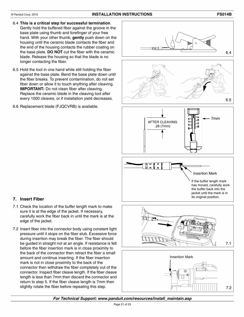
6.4 This is a critical step for successful termination. Gently hold the buffered fiber against the groove in the base plate using thumb and forefinger of your free hand. With your other thumb, gently push down on the housing until the ceramic blade contacts the fiber and the end of the housing contacts the rubber coating on the base plate. DO NOT cut the fiber with the ceramic blade. Release the housing so that the blade is no longer contacting the fiber.
6.5 Hold the tool in one hand while still holding the fiber against the base plate. Bend the base plate down until the fiber breaks. To prevent contamination, do not set fiber down or allow it to touch anything after cleaving. IMPORTANT: Do not clean fiber after cleaving. Replace the ceramic blade in the cleaving tool after every 1000 cleaves, or if installation yield decreases.
6.6 Replacement blade (FJQCVRB) is available.
7. Insert Fiber
7.1 Check the location of the buffer length mark to make sure it is at the edge of the jacket. If necessary, carefully work the fiber back in until the mark is at the edge of the jacket.
7.2 Insert fiber into the connector body using constant light pressure until it stops on the fiber stub. Excessive force during insertion may break the fiber. The fiber should be guided in straight not at an angle. If resistance is felt before the fiber insertion mark is in close proximity to the back of the connector then retract the fiber a small amount and continue inserting. If the fiber insertion mark is not in close proximity to the back of the connector then withdraw the fiber completely out of the connector. Inspect fiber cleave length. If the fiber cleave length is less than 7mm then discard the connector and return to step 5. If the fiber cleave length is 7mm then slightly rotate the fiber before repeating this step.
AFTER CLEAVING.28 (7mm)
7mm
Insertion Mark
If the buffer length markhas moved, carefully workthe buffer back into thejacket until the mark is inits original position.
6.4
6.5
7.1
7.2

For Technical Support: www.panduit.com/resources/install_maintain.asp
INSTALLATION INSTRUCTIONS © Panduit Corp. 2015 FS014B
Page 22 of 23
Clamp Arm
Clamp Arm
Clamp Pads
8. Clamp Cable8.1 Squeeze both clamp arms to open clamp pads. Place
cable between the clamp pads and release clamp arms. The fiber should be straight and the insertion mark should still be in close proximity to the back of the connector.Note: Do not shuttle cradle holder for jacketed cable terminations.
9. Turn On Laser9.1 On the end of the OCTT tool, toggle the switch to the
“I” (ON) position. If the fiber is in the correct position after this step, a multimode connector typically will either be dark or glow very dimly; a singlemode connector will typically glow moderately.
10. Cam the Connector10.1 Rotate the connector body 90° counter-clockwise
around the center axis until it stops on the cradle (when looking from rear of connector). Ensure the connector body remains seated in the cradle during camming.
10.2 Make sure the VFL cord is in contact with the connector after camming.
10.3 Note that the glow in the connector should be dark (for both multimode and singlemode connectors). If terminating in a well lit area, the glow should be dark when your hands are cupped over the connector. Do not use the glow in the front or back of the LC connector to judge the termination. Use the glow in the middle of the connector under the latch.
10.4 If connector glow is not very dim, turn off laser and un-cam the connector (per step 18). Pull the fiber back slightly and gently urge it forward until it stops on the stub fiber. (Re-check to make sure the insertion mark is near the back of the connector).
10.5 Turn the laser on and re-cam the connector. It should dim or remain dark. If not, turn off the laser and repeat the process starting at step 5.
10.6 The small visual window on the backbone will be green to indicate the connector is in the cam position.
11. Turn Off Laser11.1 Toggle the OCTT switch to the “ O” (OFF) position.
While holding connector in place, remove ferrule adapter end of patch cord from connector.
12. Place the Dust Cover on the Patch Cord (Optional)
13. Unclamp Cable13.1 Squeeze both clamp arms to open the clamp pads.
Remove cable from between the clamp pads and release clamp arms. CAUTION: DO NOT pull on cable while the connector is still held in place by the cradle. Doing so could break the fiber or create an unacceptable termination. Visual Window
8.1
9.1
10.1
10.6
11.3
Indicates improper termination
Indicates proper termination
INSTALLATION INSTRUCTIONS © Panduit Corp. 2015 FS014B
E-mail:[email protected]
Phone: 866-405-6654
For Instructions in Local Languagesand Technical Support:
www.panduit.com/resources/install_maintain.asp www.panduit.com
Page 23 of 23
Flange
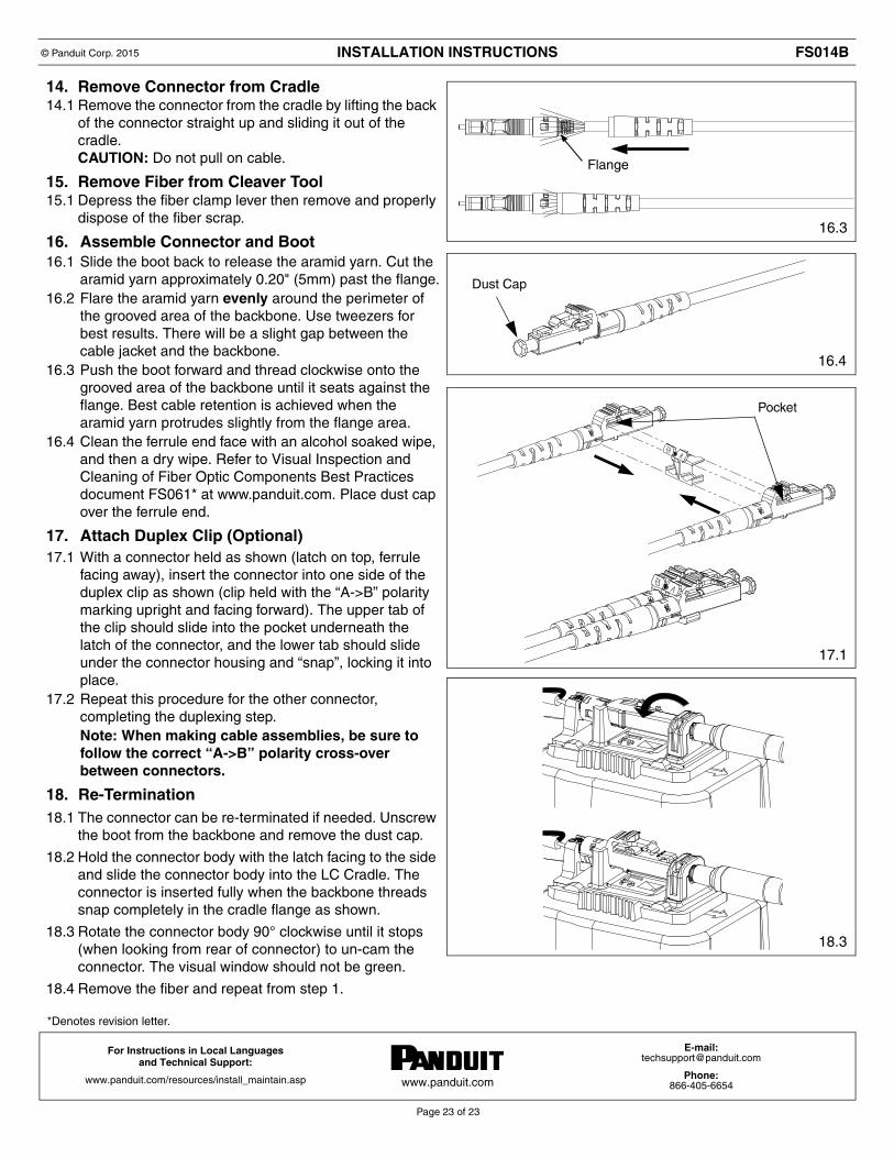
14. Remove Connector from Cradle14.1 Remove the connector from the cradle by lifting the back
of the connector straight up and sliding it out of the cradle.CAUTION: Do not pull on cable.
15. Remove Fiber from Cleaver Tool15.1 Depress the fiber clamp lever then remove and properly
dispose of the fiber scrap.
16. Assemble Connector and Boot16.1 Slide the boot back to release the aramid yarn. Cut the
aramid yarn approximately 0.20" (5mm) past the flange.16.2 Flare the aramid yarn evenly around the perimeter of
the grooved area of the backbone. Use tweezers for best results. There will be a slight gap between the cable jacket and the backbone.
16.3 Push the boot forward and thread clockwise onto the grooved area of the backbone until it seats against the flange. Best cable retention is achieved when the aramid yarn protrudes slightly from the flange area.
16.4 Clean the ferrule end face with an alcohol soaked wipe, and then a dry wipe. Refer to Visual Inspection and Cleaning of Fiber Optic Components Best Practices document FS061* at www.panduit.com. Place dust cap over the ferrule end.
17. Attach Duplex Clip (Optional)17.1 With a connector held as shown (latch on top, ferrule
facing away), insert the connector into one side of the duplex clip as shown (clip held with the “A->B” polarity marking upright and facing forward). The upper tab of the clip should slide into the pocket underneath the latch of the connector, and the lower tab should slide under the connector housing and “snap”, locking it into place.
17.2 Repeat this procedure for the other connector, completing the duplexing step. Note: When making cable assemblies, be sure to follow the correct “A->B” polarity cross-over between connectors.
18. Re-Termination18.1 The connector can be re-terminated if needed. Unscrew
the boot from the backbone and remove the dust cap.
18.2 Hold the connector body with the latch facing to the side and slide the connector body into the LC Cradle. The connector is inserted fully when the backbone threads snap completely in the cradle flange as shown.
18.3 Rotate the connector body 90° clockwise until it stops (when looking from rear of connector) to un-cam the connector. The visual window should not be green.
18.4 Remove the fiber and repeat from step 1.
Dust Cap
*Denotes revision letter.
16.3
16.4
17.1
18.3