
REACTOR TANK UT ACCEPTANCE CRITERIA (U)
83
WSRC-RP-89-208, REV 2 REACTOR TANK UT ACCEPTANCE CRITERIA (U) by gh " ........ ' W.L. Dau erty '., " .:_< , i Westinghouse Savannah River Company Savannah River Site DEC '1 A. !992_ Aiken, South Carolina 29808 Other Authors: ....... . .. . _ ...Pi This paper was prepared in connection with work done under Contract No. DE-AC09-89SR18035 with the U. S. Department of Energy. By acceptance of this paper, the publisher and/or recipient acknowledges the U. S. Government's right to retain a nonexclusive, royalty-free license in and to any copyright covering this paper, along with the right to reproduce and to authorize others to reproduce ali or part of the copyrighted paper. i 1 i rVl,l r.:,.._ • ! OISTRIBUTION O1= T#-tlS [JOC:LJfVlEN-I IS Ut,,IL.i _ "' '- i
Transcript of REACTOR TANK UT ACCEPTANCE CRITERIA (U)
WSRC-RP-89-208, REV 2
REACTOR TANK UT ACCEPTANCE CRITERIA (U)
by gh " ........ 'W.L. Dau erty '., " .:_<, i
Westinghouse Savannah River CompanySavannah River Site DEC '1 A. !992_Aiken, South Carolina 29808
Other Authors:
....... . .. . _ ...Pi
This paper was prepared in connection with workdone under Contract No.DE-AC09-89SR18035 with the U. S.Department of Energy. By acceptance of this paper, the publisher and/or recipient acknowledges the U. S.Government's right to retain a nonexclusive, royalty-free license in and to any copyright covering this paper,along with the right to reproduce and to authorize others to reproduce ali or part of the copyrighted paper.
i1
irVl,l r.:,.._ •! OISTRIBUTION O1= T#-tlS [JOC:LJfVlEN-I IS Ut,,IL.i _ "' '-
i

I)IS('I,AI_II'_I_
This report was prepared as an :_cc'_t,nt _t w¢)rk st),_nsorcd bv an a._,_cncy_Jl tlm tJnilcd •States (;ovcrn,ncnt. Neither lh, 2 I Jnitcd ,'qtatc.,; (;¢)vcrnn_c.nt n()r any ai,.cncv tI_cn'_)l, n¢_x --
any of their employees, makes ar_v ,,varr:_z_tv, cxt_rc.,;s (>r _t_licd, ()r :_.,;.';u_cs any. lc,,.al . 'lia}_ility or responsibility for the :_cct_r-:lc,,',c_ll_lctcncss, _)r u.,;cfulncss ()I any inf_r_nation, -.: .. -appan_tus, t)n×tuct, or pr_x_'css di.,;cl_scd, <_rrc l_rcscnts that it.,; u.,;c woul{t not infringeprivately ownccl ri,ehts. Reference herein to any specific couu_mrcial prt×tuct, princess, orservice hv trade nanm, tradem:trk, rnant_facl.urcr, t}r {)thcr-wi.,;c d_}cs nol llCCcss:.tr-ilv
constitute or _mply it.,; cmtorscn_cnt, rcc()m_rmndatiCm, _)r law)tin g by tt_c United State'.;(it}verminlent {_,a._v a_'.cr_cv thcrct_f. "lt_c views an_] ,_pini_ns {_1 auth_rs cxl)ru.,;.',cd hereindo m}t nccc.'-:sarllv .,;rate _r rcflccl th_.,;," <_1the I lnitcd ,St:_tcs _}_,,'cH_cnt _r any a!,.cncvI]ICIC_ f.
"l'his report has been rctm_iuccd directly lrot_ tt_c bc:;t available c_py. _:,.
Available to I)()t:. and I)()F. contractors from the Office of Scientific and Technical ".... "-_-
Information, P.O. Box 62, Oak. Rid,,e.,..,TN .."_7831• prices available frorn (015). 57(i-Sd()l , :I:TS 62()-8d1)1. - .'-
- ; " _i
Available to the public from the National Technical Information Service, U.S. l)cpartment -of Conm_erce, 5285 Port Royal Rd., Springfield, VA 22161. :_ '. •
.,.
_, ,;.' 2 ',_ :
,
- . -
• .,,.

WSRC-RP--89-208-Rev. 2
DE93 004438
: NRTSCNUCLEAR REACTOFITECHNOLOGYAND SCIENTIFIC COMPUTATIONS
Keywords: UltrasonicTestIn-Service Inspection
IGSCCPTERMCAMEL
Retention - Permanent
REACTOR TANK
UT ACCEPTANCE CRITERIA (U)TASK NUMBER: 88-001-A-1
,=
" W.L. DAUGI_ERTY MaterialsTechnology
m
ISSUED: JANUARY30, 1990
Authorized Derivative Classifier
• BAUMANN Date
SRL SAVANNAHRIVERLABORATORY,AIKEN,SC 29808.. " WestinghouseSavannahRiverCompany
Preparedfor the U. S. Departmentof EnergyunderContractDE-AC09-88SR18035
I! 1318TRIEtUTION OF THIS DOCUMENT IS UNLIMITED

PROJECT: REACTOR MATERIALS PROGRAM
DOCUMENT: WSRC-RP-89-208-REVISION 241,
TITLE: REACTOR TANK UT ACCEPTANCE L
CRITERIA (U)
TASK: REACTOR TANK ACCEPTANCE CRITERIATASK 88-001-A-1
APPROVALS
_. =,_". J_.c,;,_i._-e=_ DATE: I -- 3 0 - <_O
R. L. SINDELAR, TECHNICAL REVIEWERMATERIALS TECHNOLOGY
r.__. DATE:_-_"" _o_.f4._O..mSON.TECHN,CALnEV,EWE.Rr_TOR PROGRAMS
-H_. DATE:"_-_" _C_ •N. G. AWADALLA, MANAGERMATERIALS TECHNOLOGY
/__ _ DATE: 1.. _- c_0
J. U. STILE,--_ """MANAGER
DATE: =/,/¢0J. D. SPENCER, MANAGERNUCLEAR REACTOR TECHNOLOGY &SCIENTIFIC COMPUTATIONS
RQAP APPROVAL/'" _ / "

Revision Summary Pa_v
" Document No. WSRC-RP-89-20g Rev. No. 2 Issue Date:qb
Task ID No. 88-001-A-1 Effective Date: 1/30/90
Pa_e No. Descriotion of Revision
Revision 1 Revisions
1 1st and 2nd paragraphs of Discussion;Statements added to clarify flaw indications and requiredactions.
2 2nd paragraph;New paragraphs added to clarify scope of UT Acceptance criteria.
3 Last paragraph;Statements added _o clarify scope of the UT Acceptance Criteriareport (WSRC-RP-89-208).
Figure 1 "Flaw" added to title.Chart revised for clarification and consistency with text.
Revision 2 Revisions
. 2 Item 4 of 2nal paragraph; requirements for documenting weld flaws,. and geometric reflectors clarified.
Art. 1 Glossary Item 11; correct typographical error.Item 13; correct typographical error and make editorial change for,i
clarity.
a,

INTRODUCTION
. The SRS reactor tanks_are constructed of type 304 stainless steel, with 0.5 inch thick walls. An-, ultrasonic (UT) in-service inspection program has been developed for examination of these tanks, in
accordance with the ISI Plan for the Savannah River Production Reactors Process Water System(DPSTM-88-100-1). Prior to imtiation of these inspections, criteria for the disposition of any
, indications that might be found are requh'ed. A working group has been formed to review availableinformation on the SRS reactor tmaks and develop acceptance criteria. This working group includesnationally recognized experts in the nuclear industry. The members and their affiliation are listedbelow.
Members of the SRS Tank Acceptance Criteria Working Group
D. C. Adaa_onis Westinghouse Electric CorporationN. G. AwadaUa SRSN. P. Baumarm SRSJ. A. Begley Westinghouse Electric CorporationS. H. Bush Review & Synthesis AssociatesG. R. Caskey, Jr. SRSW. E. Cooper Teledyne Engineering ServicesW. L. Daugherty SRSH. S. Mehta General Electric Company .J. G. Merlde Oak Ridge National LaboratoryS. Ranganath General Electric CompanyR. L. Sindelar SRSJ. C. Tobin SRS ConsultantS. Yukawa SRS Consultant
The working group has met three times and produced three documents describing the proposedacceptance criteria, the technical basis for the criteria and a proposed initial sampling plan. This report
" transmits these three documents, which were prepared in accordancewith thetechnicaltask plan andquality assurance plan for this task, task 88-001-A- 1. In addition, this rel_rt summarizes theacceptance criteria and proposed sampling plan, and provides further interpretation of the intent ofthese three documents where necessary.
DISCUSSION
The acceptance criteria are contained in EDG-89.47, provided as Attachment 1 to this report. Thesecriteria def'me two standards for characterizing UT indications. With the exception of geometric
. reflectors, an indication greater than or equal to 20% through wall in depth is considered a flaw.Detection of flaws smaller than those used for UT qualification (3.0" :t:0.5" in length and 0.2" 4-0.1"
" in depth) is not required. However, if smaller indications are detected, they shall be recorded andconsidered by the analyst for combination with adjacent indications. This statement does notconstitute a requirement for the UT inspector to detect flaws smaller than those used for qualification.
Haws which are smaller than the reexamination standard (5 inches) are acceptable for continued. operation until the next normal inspection in 5 years. Haws greater than or equal to the reexamination
- standard, but less than the acceptance standard are acceptable for continued operation for a period of18 months. Flaws v'eatcr than or equal to the acceptance standard (10 inches) require additionalanalysis and evaluation using flaw, material, and operating conditions specific to the flaw location to

J..XI. Stone WSRC.RP.89-208-Revision 2Page 2 Task Number 88.001-A-1January 30, 1990
determsle acceptability for continued operation. The acceptability of a flaw exceeding the acceptancestandard will be reviewed and approved by WSRC and DOE management. Flaws greater than orequal to the acceptance standard will also require an expansion of the sample size of the presentinspection. Finally, inch'_ations less than 20% through wall in depth, and longer than twice the _"acceptance standard, are subject to additional evaluation, flaw specific analysis, and/or examination.These criteria are illustrated in Figure 1.
The Reactor Tank LT Acceptance Criteria were developed for use in evaluating and dispositioningindications found in the heat affected zone or base metal st,r','ounding tank assembly welds. This isconsistent with DPSTM-88-100-1, which identifies specific IGSCC categories for each type ofweldment in the reactor tank. Only the heat affected zone portions of these weldments are susceptibleto IGSCC. The weld metal is not susceptible to IGSCC. Beyond the guidelines developed forIGSCC by the working group, the following guidance is provided for addressing any indications thatmight be found within the weld metal or UT signals resulting from geometric reflectors:
1. Any UT signal that is interpreted by the level III inspectors as a reflector due to weld geometry isacceptable. It should be documented for future reference (see item 4 below).
2. Any UT signal that is interpreted by the level HI inspectors as a discontinuity which is embeddedentirely within the weld and does not penetrate the tank surface is acceptable as is. Suchdiscontinuities are assumed to be a result of tank fabrication. As such, these weld imperfectionswould have been accepted by the code of record enforced during tank fabrication. There is noknown mechanism for the propagation of weld flaws in the SRS reactor tanks. Thus, theypresent no concern to the structural integrity of the tank. These indications should be documentedfor future reference (see item 4 below).
3. Any UT signal that is interpreted by the level HI inspectors as a discontinuity within the weldvolume which penetrates the ta',: surface should be evaluated in accordance with the acceptancecriteria of this document.
4. Since the UT qualification is based on cracks of 3.0" + 0.5", shorter cracks may not be dete,cted.Similarly, geometric or embedded weld reflectors shorter than 2.5" may not be detected. Theseweld reflectors need not be considered for combination with adjacent indications. Embeddedweld flaws whose length is greater than or equal to 2.5" shall be documented for future reference Iand should include, to the extent to which the equipment and inspectors are qualified, the location Icoordinates and a cross-sectional plot showing the location of the reflector with respect to theweld. Hard copy data from an automatic data acquisition system (such as the Intraspect 98)which is capable of providing an overlay for dLrectcomparisons with subsequent inspections isconsidered adequate for this purpose.
Attachment 2 (EDG-89.48) contains the technical bases considered in developing these criteria.Available information on onk stress analyses, material properties, IGSCC behavior, the UTexamination program and fracture mechanics anal,, ses _ssummarized.
A sampling plan is described in EDG-89.49, pro,. _dedas .Attachment 3. This sampling plan appliesonly to the initial inspection. The scope of subsequent inspections will depend in part on the results ofthe first inspection. The proposed sampling plan calls for inspection of all tank shell longitudinalwelds, one-third of the tank shell circumferential welds, portions of the T weld that are accessible,base metal regions and identified areas of repair work.
ill rpI'_'nlllq

J. M. Stone WSRC-RP-89-208-Revision 2Page 3 Task Number 88-001.A.1January. 30, 1990
The proposed sampling plan does not specifically identify the regions of base metal to be inspectedduring the initial inspection, lt is not the intent of the working group that all base metal in the
. accessible regions be examined. Rather, only selected portions need be examined. Specifically, it is,- proposed that the initiaTexamination cover the narrow regions of base metal bounded by (1) tines
extending from each tank shell longitudinal weld, (2) a circumferential line 12 inches above the center. girth weld, and (3) a circumferential line 12 inches below the center girth weld. This gives coverage
of two narrow strips of base metal, two feet in height, with the c_'umferential girth weld dividingeach strip in half. Inspection of these regions will provide assurance that no defects are propagatingfrom the longitudinal welds into the base metal.
The three documents provide the necessary acceptance criteria for the disposition of UT indicationsthat might arise during inspection of the SRS reactor ranks. The criteria control acceptance of flawsbased on length as sized by UT measurement; no restrictions are ph_cedon the depth of the flaw. Theconsiderations used to develop these criteria and the sampling plan provide confidence that any flawof si_ificant size will be detected in a timely manner and dispositi_aed in such a way as to preservethe structural integrity of the reactor tanks and provide confidence in the continued safe, reliableoperation of the SRS reactors. The disposition of flaws at a measured depth less than or equal to thetank wall thickness is handled as an operational decision with leakage limits controlled per the siteTechnical Specification 3.3.2. This Technical Specification precludes reactor ogeration with leakagefrom the process water system pressure boundary, as defined in the Specification.
WLD:sgmSRL-EDG-890166
i! rl '111 rollli Ilqllr IIII ira, ,_1, I11 IPll'IIl_,lplIIII

Figure 1. Flow Diagram of UT Flaw Indication Disposition Procedure
Depth greater than or _ I
equal to 20% of tank _ Effectiveflaw lengthgreater thanwall thickness? twice the acceptancestandard?
: 1
l flaw specific analysis,_Effectivelength greater thanor _ _md/orexaminationJequal to reexaminationstandard ?
examination fr_uency"k.... )
Reinspect duringnext long shutdown
Effectivelengthgreater thanor equal to accep_ standard ?i.
k _l°"g shu_°w_J................ __ ........................... -_______- .... ""Z__ _'- ..... __
Expand sample forthe present inspection,perform flaw-specificanalysis J
............. -- - ..-_ ..............
Flaw is acceptable?

J. M. Stone WSRC-RP-89-208-Revision 2Page 4 Task Number 88-001-A.1January 30, 1990
ATTACHMENT NO. 1
11

EDG-89.47-REVISION 1
PROCEDURE FOR EVALUATION OF REACTORTANK INSPECTION RESULTS (U)
DECEMBER 1989
Patent Status
This internal management report is beingtransmitted without DOE patent clearance,and no further dissemination or publicationshall be made of the report without priorapproval of the DOE-SR patent counsel.
Westinghouse SavannahRiverCompanySavannahRiverLaboratory
P.O. Box 616Aiken, SC 29802
-. PREPAREDFORTHEU.S.DEPARTMENTOFENERGYUNDERCONTRACTDE.ACO9-88SR18035
II ..:

PROCEDURE FOR EVALUATION OF REACTOR__ANK INSPECT_I_)_N,_RESULTS(Ut
DOCUMENT: EDG-89,47-REVISION 1
REVISION1PREPAI_ED BY:
W. L. DAU_HERT_, DATEw 1" GtIOUSE,SRL
REVISION I
. REVIEWED BY| -
D. C. ADAMONIS, /DA_E _EGLEY, -" C..../DATE 'WESTINGHOUSE WESTINGHOUSE
J/5_. MO r DATE R.L. SINDELAR, DATE_ESTINGHOUSE, RRD WESTINGHOUSE, SRL

This approval page from the original issue of the Reactor Tank UT AcceptanceCriteria by the Tank Acceptance Criteria Working Group is in:luded in Revision 1as a record of the technical expertise behind these acceptance criteria. Revision !to this document was made to clarify the criteria and not to alter the technicalcontents.
_ROCEDURE FOR EVALUATION OF REACTORTAlqK INSPECTION RESULTS
PREPAREDBY:
_fj.__EGLEY, ("/ D"ATE W. L DM._HERT_, SRi., DATEWESTINGHOUSE
REVIEWED BY_i
/
ii i ii
D. C. ADAMONIS° / ,OATE H. $. MEHTA,WESTINGHOUSE GENERAl., ELECTRIC COMPANY
N. G. A DATEOAJCRIDGE NATIONAL LABORATORY
, /
. . _,-',.._.,_.,,._,,.-,,.. f.._r,,.N.P. BAUMAN_IISRL DATE S. RANGANATi_ DATE
GENERAL ELECTRIC COMPANY
R. L SINDELAL Sl_
VIEW & SYNTHESIS _TE$
_ .Tom - - ,oA'rr.
W. E. COOPEL /- DATE S. YUK,_ - "-- I_._,TETELEDYNE ENGINEERING SERVICES

TABLE OF CONTENTS,,,..
• I. INTRODUCTION AND APPROACH ............................. 1
II. FLAW CHARACTERIZATION ............................. .... 1
III. REEXAMINATION STANDARD ................................ 2 [
IV. ACCEIYrANCE STANDARD FOR EXAMINATION ................... 2
V. PROCEDURE FOR ACCEPTANCE BY ANALYSIS ................... 2
VII REFERENCES ........................................... 3
VII. GLOSSARY ...... • ...................................... 5 1

Revision Summary Pa_e
. P
_ Document No. _ Rev. No. I Issue Date: .L2./.2.Q./.._
Task ID No. _ Effective Date"r
Pa2e No. Deseriotion of Revision
i Updated to reflect revised page numbering.
1 Ist paragraph;Revised to clarify applicability to IGSCC.
1 2nd paragraph added to clarify management treatmentof leakage from the Process Water System Pressure Beundary.
I Last paragraph;Editorial changes made.
2 2hd paragraph;Rules for crack combination are clarified.
2 Section II, "Reexamination Standard", 2hd paragraph:Word "crack" deleted.
2 Section IV, "Acceptance Standard for Examination", Isr paragraph;Words ".°identification and..." added for clarification.
Glossary Changes/additions made in items 5, 9, and 12; New item 14- added; Balance of numbers changed to reflect this addition.
- These changes provide further clarification of the test discussion.
' '_ ...... l_lJ '' ,' ,,,, ql, _, Iplql1'III

I. INTRODUCTION AND APPROACH
The ISI Plan for the Savannah River Reactor Process Water System (I) specifies anultrasomc inspection of the reactor tanks on a nominal five year frequency. The procedurefor the evaluation of reactor tank inspection results is described in the following paragraphs.
" The scope of this procedure is limited to the disposition of planar flaws with an approach thatparallels that of Section XI of the ASME Boiler and .Pressure Vessel Code. This procedurewas also developed specifically for evaluating and dispositioning indications found in theheat affected zone or base metal surrounding tank assembly welds. This is consistent withreference (1), which identifies specific IGSCC categories for each type of weldment in thereactor tank. The weld metal is not susceptible to IGSCC.
The evaluation of planar flaws is performed with the assumed condition of a through wallflaw depth along the entire length of any UT indication with reported depth greater than orequal to 20% through wall. The flaws are dispositioned based on flaw length only therebyaddressing the structural safety significance of the flaw. Ultrasonic inspection results offlaws greater than or equal to 20% through wall in depth including through wall flaws arecontrolled by management decisions in regards to reactor operation. Leakage limits frompotential through wall flaws are governed by the site Technical Specification 3.3.2. Inaddition to placing specific limits on normal process water losses, this TechnicalSpecification does not permit reactor operation with leakage from the process water systempressure boundary, as del'reed in the Specification.
Rules for the characterization of flaw sizes are presented, including interaction effects. Theevaluation procedure is based on comparing the effective size of an indication with two sizecriteria; a reexamination standard and an acceptance standard. The effective flaw length is aparameter that treats flaws as ff they were through wall and provides for the combination ofcracks in close proximity. Both the reexamination standard and the acceptance standardprovide reasonable assurance that a crack will not exceed one-half the allowable flaw sizeprior to the next inspection.
Ali UT inspection results are recorded and available for future reference. Backgroundinformation, crack growth and fracture analyses and safety margins which provide thetechnical bases for this flaw disposition procedure are included in Reference 2. In particular,the Reference 2 discussion of UT detection and sizing capabilities provides a basis for theevaluation procedures.
The general approach for evaluation of the UT inspection results is outlined in Table 1.Sections II through V provide details for the evaluation.
II. ]_[..AWCHARAC'I"I_IIT_ATIOIg
A flaw is def'med as a planar indication (geometric indications are not considered I.,lanarindications) with a depth greater than or equal to 20% of the reactor tank wall thickness. Anindication less than 20% through wall in depth but greater than twice the acceptance standard inlength is subject to supplemental examination. Detection of flaws shorter than those used forUT qualification (3.0" _ 0.5") is not assured. However, if shorter flaw indications aredetected, they shall be recorded and considered by the analyst for combination with adjacent Iindications.

EDG-89.47-REVISION 1Page 2December 20, 1989
A flaw is characterized by its effective length as defined below. Limitations are placed uponeffective flaw length. No limitations are placed upon flaw depth. Limitations on acceptableeffective flaw length are based on the conservative assumption of 100% depth along the fulleffective flaw length.
If the distance between a pair of colmear flaws is less than or equal to 2.6 inches, the pah"of
flaws shall be considered to be a single flaw of effective length equal to the distance between lthe farthest flaw ends. If two flaws are parallel but not colinear and the perpendicular distancebetween them is less than or equal to 0.5 inches, then the above rule shall also apply todetermine the effective flaw length. This procedure may result in the combination of severalpairs of flaws into a single flaw.
III. R_'_'_XAMINATION STANDARD
Flaws with an effective length less than 5 inches do not exceed the reexamination standard.For these flaws, the original examination frequency is maintained,
Flaws with an effective length greater than or equal to 5 inches exceed the reexaminationstandard. The physical flaw length and depth are to be reported as well as the location. Theseflaws shall be reinspected during the next three inspection outages. In the event an indicationremains essentially unchanged during these subsequent three inspections, future inspectionswill revert to the original schedule.
IV. _ STANDARD FOR EXAMINATION
Flaws with an effective length greater than or equal to 10 inches exceed the acceptance
standard. Supplementary examinations shall be considered to assist in the identification and I-characterization of the flaw. Urdess such supplementary examinations result inrecharacterization of the flaw as one which has an effective length of less than 10 inches, thetank shall be subject to additional examination and evaluation for acceptance by analysis.
The additional examinations shall be performed on welds within the same inspection category,with the total length of welds for which the additional examination is performed being no lessthan that originally scheduled for the current ex_ntnations. If the additional examinationsreveal any flaws with effective length greater than the acceptance standard, the additionalexamination shall be expanded to include 100% of ali welds within that examination category.
The procedure for acceptance by analysis is presented in Section V.
V. PROCEDURE FOR ACCEPTANCE BY ANALYSIS
This section describes the general approach and requirements to be followed in the acceptanceby analysis evaluation required for flaws with an effective flaw length in excess of theacceptance standard. If the criteria for acceptance by evaluation are satisfied, continued tankoperation for the defined evaluation period is permissible.
The technical approach and significant elements are described in Reference 1. The basicapproach of the fracture safety analysis is as follows:
1. Consider the measured _ dimensions of the flaw or flaws included inthe effective flaw length as determined by Section II.
2. Incorporate an allowance for inspection measurement error.
iI....

EDG-89.47-REVISION 1Page 3December 20, 1989
3. Define the interval for the next inspection of the flaw.
. 4. Incorporate a flaw growth allowance for SCC based on a selected time tothe next inspection.
5. For the crack length at the end of the evaluation period, compute the loading" intensity based on the principles of linear elastic and elastic plastic fracture
mechanics. Plasticity effects must be included or shown to be negligible.Applied and welding residual stresses must be included.
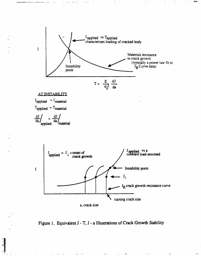
6. Using a crack growth resistance curve approach, determine if appropriatesafety margins are available for protection against unstable crack growth. Incomputing the loading intensity in terms of K or J, multiply the pressureloading by a factor of 3.0 for nomaal and upset conditions or the pressureand seismic loading by a factor of 1.4 for accident conditions. As a checkof the degree of extrapolation of fmcvare testing data evaluate crack stabilityin both J vs. T and J vs. a plots using mathematically equivalent fits asillustrated in Figure 1.
7. The criteria for acceptance by evaluation are satisfied for the evaluationperiod if no unstable crack growth is predicted.
Key factors in the analysis have been delineated and the safety margins with respect to t_loading have been specified. Fracture toughness and associated crack growth resistance curveproperties depend on position in the tank as the fluence depends sensitively on location. Locationand tank specific value_;, if avaflable_ should be used. Flaw growah allowances for IGSCCshould consider, to the extent meaningful results are attainable, the past performance of theSavannah River reactor systems and a growing database of laboratory observations. A summaryof information currently available in these areas is presented in Reference 2.
REFERENCES:
1. DPSTM-88-100-1, "ISI Plan for the Savannah River Production Reactors Process WaterSystem," P. R. Vormelker, R. L. Sindelar and W. L. Daugherty, Savannah RiverLaboratory, December 1988.
2. EDG-89.48, "Technical Basis For The Savannah River Reactor Tank AcceptanceCriteria," D. C. Aclamonis et al., May 1989
ii

EDG.89.47.REVISION 1Page 4December 20, 1989
p
Table 1. General Approach for Evaluation of LTTInspection Results
REEXAMINATION STANDARD ACCEPTANCE STANDARD
< ----" > < < = >
RECORD YES YES YES YES YES YES
ACC. NDE (EACH OUTAGE) NO YES YES YES YES* YES*
ACC. NDE + EXPANDED NO NO NO NO YES* YES*SAMPLE
EVALUATION (ANALYSIS) NO NO NO NO YES* YES*
YES = action required
NO = no action required
ACC = accelerated
* Lengths greater than or equal to I0 may be verified by supplemmtal examinations.
- ' " " rr _ , i, , _ r ,r ,,N ,;p
R'

GLOSSARY
1. Acceptable Effectsve See Acceptance Standard.Flaw Length
2. Acceptance Standard Flaws with an effective length less than or equal to 10 inches but equalto or greater than 5 inches.
3. Allowable Flaw Size Critical (unstable) flaw size calculated by fracture mechanics aftermultiplying normal operating stress by 3 and faulted stresses
. (P + DBE) by 1.4.
4. Effective Flaw Length Total length of a flaw or combination of flaws when separated by nomore than 2.6 inches.
5. Effective Flaw Size/ Measured flaw length and depth, including proximity considerations ICharacterization for adjacent flaws. ]
6. Evaluation Procedure Comparison of effective flaw size to reexamination standard andacceptance standard.
7. Examination Category See Ref. 1 (to dec. 1). For tanks the longitudinal and circumferentialwelds plus regions of repair if they exist.
8. Factor(s) of Safety Factors of 3.0 on pressure for normal and upset condition or 1.4 onpressure plus design basis earthquake for accident (faulted) conditions.
9. Flaw Any planar indication with a depth greater than 20% of the reactor tank iwall (geometric indications excluded). I
10. Flaw Growth Flaw growth due to IGSCC (or other mechanisms such as fatigue)occurring in a specified time interval.
- 11. Flaw Growth Allowance See flaw growth; where time interval is that to next inspection.
12. Flaw Indication Ultrasonic response determined to be a discontinuity other than geometric.(Or Indication)
13. Inspection Measurement Possible error_ i_nlength measurement for a given ultrasonic procedure [Error wherein underprediction of length is assumed. The magnitude is assumed I
to b¢ 0.5 inches.
14. Flaw Identification A process which identifies the type or source of the flaw including, butnot limited to, fabrication volumetric flaws or service-induced flaws.
15. Inspection Outage Long shutdown used to conduct UT; nominally assume 18 monthsbetween inspection outages.
16. Physical Flaw Length Length of a discrete flaw.
17. Reexamination Standard Flaws having an effective length equal to 5 inches.
18. Residual Stress Those stresses usually resulting from contraction during welding andweldment restraint.
19. Resistance Curve Fracture mecharfics technique t,_determine margins against unstable crack- growth.
20. Unstable Crack Growth A combination of flaw length and loads calculated to lead to flaw instability.
..... .....
\ ! J I - vsT,. \ - ! appled applied
._//'4""chazact_rizesloadingofcrackedbodyJ j
/ _ _ _ tocrackgrowth_/ l "__ . ._" (typically a power law fit to
/ _bi_, -'"-......._.. JRC_I',_,_,.v" pointf-
.V
E dJ
T-__ATNST_ILrrY
Japplied = J_
Tapplied = Tmatcrial
_J__/_ ___/
/ J....._vsaJ _d--Ji-_sy_of_..... / ¢o__m__s_m_app _v,_J. _uwu. /
_ starting crack size
a, crack size .
Figure 1. EquivalentJ - T, J - a Illustrationsof CrackGrowth Stability

J. M. Stone WSRC.RP-89-208-Revision 2Page 5 Task Number 88-001-A.1January 30, 1990
ATTACHMENT NO. 2
q
A

EDG-89.48-REVISION 1i.
TECHNICAL BASIS FOR THE SAVANNAH RIVER
REACTOR.TANK ACCEPTAP_CE CRITERIA (U)
DECEMBER 1989
Patent Status
This internal management report is beingtransmitted without DOE patent clearance,and no further dissemination or publicationshall be made of the report without priorapproval of the DOE-SR patent counsel.
Westinghouse Savannah River CompanySavannah River Laboratory
. P.O. Box616Aiken, SC 29802
" PREPAREDFORTHEU.S.DEPARTMENTOFENERGYUNDERCONTRACTDE.AC09-88SR18035

J
!
[ _ TECHNICAL BASIS FOR THE_SAVANNAH RIYER, REACTOR TANK ACCEPTANCE_CRITERIA (U)I!
DOC--'I._4E_F; EDG.89.48-REyISION 1
I!
!
REVISION 1PREPARED BY:
W. L. DAUGI_RTY,/ DATE
I WESTINGHOUSE, SRL!
REVISION 1
REVIEWED BY:
_O. C. ADAMONIS, ' DATE ..I- j. A,.BEGLEY, k.. _/ DATEWESTINGHOUSE / /,._.---.-"W_STINGHOUSE
/ -/Y-g7J_M. MORRISON, 1 DATE DATE_STINGHOUSE, RRD WESTINGHOUSE, SRL

This approval page from the original issue of the Reactor Tank UT AcceptanceCriteria by the Tank Acceptance Criteria Working Group is included in Revision las a record of the technical expertise behind these acceptance criteria• Revision !to this document was made to clarify the criteria and not to alter the technicalcontents.
1"_ TECHNIC_ BASIS FOR THE SAVANNAH RIVE!_.- REACTOR TANK ACCEPT_,SNCE CRI_.,]_
PREPARED
q
A
/
.._.4L_.,'/<_..._<._._,,.,.;, ._y,.._,-f ,,,___#_...._. _ "e_ _
D• C. ADAMONIS, / ASATI_- W• L. DAU_HERT/_, SRL DCkTi_WESTINGHOUSE
H. S. MEHTA, 'D_(Ti_GENERAL ELECTRIC COMPANY
W. Ep COOPER, Y DATE R. L• SINDELAR, SRI., DATETELEDYNE ENGINEERING SERVICES
REVIEWED BY I
- sl ,it, -,i,/,,N.G. AWADALLA, SRL DA2_E- _;. MERKI.,_ DATE
O,KR_W'%SAnON,_L_80_TO_Y
X.e. BAUMANN. SRL DATE S. R-A_GANATHo - "DATE
• . DATE l.£. TOBI24 DATqEWESTINGHOUSIg
"_'" "/ il(.,P._/-_l,uE.s.gJusH, " " "s. - _ATtREVIEW& SYNTtlESISASSOCIATES _.
.

- TABLE OF CONTENTSQ
II. DISCUSSION ............................................. 2
Stress and Structural Evaluation ................................... 2Fracture Toughness Properties ................................... 3IGSCC Behavior ............................................ 5UT Examination Program ......................................... 6
Examination Methodology ................................... 7Detection and Sizing Capabilities ................................. 8
Sample Calculation and Acceptance Criteria ............................. $
Acceptance Standard " 9Reexamination Standard ..................................... 9Long Shallow Indications ..................................... 9Crack Combination Rtdes ..................................... 9
. Summary of Conservntisms and Assumptions 10
III• CONCLUSIONS ........................................... 10
I V. REFERENCES I• • • • • • • • • • • • • • • • • • • • • • • • • • • • • • • • • • • • • • • • • • • • • 12 t
- i

Revision Summary Pale
Document No. _ Rev. No. I Issue Date"
" Task ID No. 88-001-A-1 Effective Date"
Pa2e No. Descriotion of Revision
i Updated to reflect revised page numbering.
1 4th paragraph;Statement in parenthesis added for clarification; last sentencechanged for consistency with EDG-89.47.
1 Last paragraph, item #2;Change made for clarification and consistency with ASME Code,
•" Section XI.
5 Isr line;Corrected reference citation.
5 1st and 2hd paragraphs; last sentence in 3rd paragraph;, Information added to document material properties.
5 2nal paragraph under "IGSCC Behavior";We,'d cracking frequency revised based on new data.
7 2nd paragraph; item 1; Terminology corrected.
8 3rd paragraph;Last sentence added to clarifiy UT examination requirements.
8 Last paragraph;
i Last sentence added to clarify UT criteriaacceptance applicability.
9 3rd p_ragraph;" 2hd sentence added for clarification of basis for selecting locations
i A and B.
9 6rh paragraph;Section added to address long shallow flaws.
I 13 References #16 and #23 updated.Figure 4 (sec) deleted from the captions of both diagrams.
A-I 4th paragraph;Sentences added to clarifyresidualstressdistribution.
• A-2, A-3 Additional informationadded to address circumferentialcracks.
A-5 References /_5. and A6. added.

Revision Summary Parr
Document No. -_ Rev. No. I Issue Date: .L_ "P
Task ID No. 88-001-A-1 EffectiveDate
Pale No. DescrintionofRevision
Figure A2 Labels to the right of each diagram corrected.
Figures AS, A6 Curve labels added.
i
I. INTRODUCTION
" The tank of a Savannah River Site reactor is a cylinder approximately 16 feet in diameter and 14 feethigh and is not pressurized except for a 5 psig helium blanket gas in addition to the hydrostatic head
" of the heavy water 0920) moderator. The tanks are made of American Iron and Steel Institute Type306 stainless steel fabricated into cylindrical shells with four to six wrought plates per vessel, 0.5inches thick. The shells were made up in two flat half-sections for later rolling and welding. Thetank bottom section containing the moderator effluent nozzles was welded to the shell m a T-jointconfiguration. All joining was performed with multipass Metal Inert Gas (M_IG)welding.
An ultrasonic in-service inspection program has been implemented for the Savannah River Site (SRS)reactor tanks. The rationale for implementation of this program is to 1) provide informationconcerning tank status necessary for life extension studies and planning preventive maintenance and2) provide additional assurance concerning the continued safe and reliable operation of the tank overand above that already established by design, analysis, prior examinations and operating experience.The approach of this periodic in-service inspection program is consistent with Section XI of theASME Boiler and Pressure Vessel Code and the "ISI Plan for the Savannah River ProductionReactors Process Water System". Baseline examinations will be accomplished during scheduledoutages over the next five years of operation and "in-service" examinations will be performed duringsubsequent five year intervals.
A key step in preparing for the reactor tank examination program is development of appropriateacceptance criteria, criteria for more frequent surveillance of acceptable flaws, and the threshold flawsize above which the examination sample size must be expanded. A working group was formed toreview available information and develop these criteria. The criteria are contained in a companiondocument ( 1). This document summarizes the technical information and approach on which thecriteria are based. Although these criteria are based on reasonable interpretation of the best
• information available, they are subject to change as additional experience is developed.
The acceptance criteria provide three response levels to the ultrasonic testing (UT) results based oneffective length standards. If an indication is greater than or equal to 20% through wall, it isconsidered a flaw (excluding geometric indications). An indication less than 20% through wall butmore than twice the acceptance standard in length is subject to additional evaluation, flaw specificanalysis and/or examination.
If a flaw is found which is less than the reexamination standard, it is recorded along with the otherinspection documentation ,andno other action is necessary.
If a flaw equals or exceeds the reexamination standard, but is less than the acceptance standard, twoactions are taken:
1. The flaw is reported as acceptable, and2. The flaw is subject to an increased inspecuon frequency in the future.
Finally, if a flaw equals or exceeds the acceptance standard, five actions are taken:
1. The flaw is reportgd.2. Supplemental examinations using other methods and techniques may be considered to ]
. " optimize flaw identification and charactertzauon, I3. The sample size for the current examination is expanded,4. The flaw is analyzed for acceptance, and5. The flaw is subject to an increased inspection frequency in the future.
i -

Page 2 EDG-89.48-REVISION 1December 20, 1989
II. DISCUSSION-m
Several elements were combined in developing the acceptance criteria. These are discussedseparately in this section. The elements include tank stress analyses, fracture toughness properties,intergranular stress corrosion crack (IGSCC) behavior, and details of the planned inspectionprocedure. The combination of these elements is then illustrated with sample calculations.
Stress and Structural Evaluation
Over the history of the SRS reactor program, several structural evaluations have been performed tocharacterize the response of the reactor tank under various design, operating and accident conditions.The tank designs for P, K and L reactors are identical. The earliest analyses were consistent with theConstruction Code for the tanks, Section Viii- Division 1. Although there was only one Division ofSection VIII at that time, the qualification is useful to later developments. These evaluations,consistent with the Code requirements and with the specifications, considered only a Design Pressureat a Design Temperature.
A complete stress analysis and structural evaluation of tank stresses was performed by Quad.rexCorporation in 1985 (2). These analyses included normal operating conditions and seismic loadings,and applied the criteria of the 1983 Edition of Section VIII - Division 2. Division 2, first issued in1968, provides "alternative" rules, alternative to those of Division 1, for the design of pressurevessels. The difference is often characterized in terms of the basic approach to design: Division 1applying a "design-by-rule" approach, traditional to the design of pressure equipment for specifiedDesign Pressures and Design Temperatures; and, Division 2 applying a "design-by-analysis"approach, utilizing modern engineering capabilities, including evaluation of complex operatingconditions and geometries. Use of the alternative rules was necessary for the Quadrex evaluation ofthe complex geometries of the tanks when subjected to service and seismic loadings. Quadrexcohcluded that the applicable Code allowable stress criteria were satisfied.
Of more significance in the context of the present report is the similarity between the ASME SectionIII (III) rules for the design of Class 1 nuclear components, such as reactor pressure vessels, andthose of Section VIII - Division 2 (VIII-2). The "design-by-analysis" methodology is imposed inboth. The major difference lies in the method for evaluation of stresses which result from abnormaloperating conditions, such as earthquakes. III provides for four different sets of allowable stresslevels, Service Levels A, B, C and D. The lowest, Service Level A, uses allowable values identical tothe basic values of VRI-2. VIII-2 permits a 20% increase in certain of the allowable stresses whenseismic loadings are considered, an increase greater than that generally used with III for Design BasisEarthquakes (DBE) and less than that generally used with III for Safe Shutdown Earthquakes (SSE).Since the Quadrex evaluations included seismic stresses, advantage was taken ot the 20% increase incertain allowable values.
The tank is generally divided into several regions for analytical purposes. The major portion of thetank wall is a thin-walled cylinder with no structural discontinuities. The bottom tube sheet assemblyis treated as a composite flat plate incorporating the stiffness of the piping penetrations as well as theperforated top and bottom plates comprising the bottom shield surfaces. The outlet nozzles and otherlocal areas of complex configuration are currently analyzed by finite element techniques. Thisapproach was followed by Quadrex, considering the stress effects of the following normal operatingand seismic loadings:
1. 5 psi overpressure (plenum gas) plus 7.3 psi hydrostatic pressure (15.5 feet of DTO).2. 1.32 psi equivalent hydrodynamic pressure applied to the tank wall from vertical seismic
excitation.
J
,,,,.rl,,l_lr ................................ il ....... ,I,I '1'" ..... ,,,rqrllIi, rllll[,, ............... , .... ,rl_,,_,, i r 'rl,', ,111'r1111,' ,, ,111..... rlll_lll_,"qrllf_'_'il_",,r_,llt,r,ff-

Page 3 EDG-89.48-REVISION 1December 20, 1989
• 3. Vertical loads on the bottom tube sheet of 224,600 lbs. (deadweight) and 126,820 lbs., (seismic).
4. Combined maximum horizontal direct shear and overall bending moment from horizontalseismic motions (E-W and N-S directions).
5. 5 psi internal pressure on the bottom tube sheet assembly.
Quadrex compared their calculated stress intensities with the VIII-2 allowable stress intensities,including the 20% increase m allowable values when appropriate. Ali stresses were found to meetthe requirements specified in VUI-2. Table 1 of the present reportcopies the information containedin Table 6-2 of the Quadrex report with respect to calculated stress intensity and location, butinstead of comparing the calculated values with the VIII-2 values, the III Service Level A valuesare used. Ali calculated stress intensities are less than the allowable values.
In order to complete the tank structuralevaluation, Qtmdrex also evaluated three modes of tankbuckling: general compression, general shear and toe buckling. The safety margins againstbuckling were determined by dividing the critical buckling stress by the calculated compressives_'ess for each of the three buckling modes considered. In all cases, the safety margins wereestimated to be greater than 10.
These evaluations clearly show that the tank stresses under normal and seismic conditions meetthe criteria of Section III of the Boiler and Pressure Vessel Code applicable to nuclear reactorvessels. Therefore, it is consistent in developing an inspection program, including acceptancecriteria, to follow the philosophy of the Section XI rules of the Code applicable to thepreservice and inservice inspection of nuclear vessel_.
Fracture Toughness Properties
Irradiation programs conducted as part of the Reactor Materials Program (RMP) providemechanical property data for fast fluence (En > 0.1 MeV) and displacement damage levels atand above tank wall fluence levels. The irradiated mechanical property results, with attention to
. the application of fractnre toughness to the SRS tank sidewall regions, are discussed in thissection.
Over 1000 Type 30,1 stainless steel mechanical and corrosion properties specimens wereobtained from the R-Reactor process water piping for the R.MP studies, approximatelyone-third of which were selected for irradiated properties testing. The archival material selectedfrom eight separate rings of 16-inch diameter piping each contained a circumferential weld.This provided potentially 16different heats of 1950's vintage stainless steel. The compositionof this material is consistent with that of the plates used to fabric_tte the reactor tanks (3). Thespecimens were machined into tensile bars (1"),Charpy V-notch (Cv) and compact tension(CT) specimens. Separate specimens sampled base metal, weld metal and weldheat-affected-zone material. A total of 283 specimens (86 CT's, 119 Cv's and 78 "Fs) have beentested in the unirradiated properties or baseline testing program. A total of 325 specimens havebeen allocated for the irradiated properties testing program. This includes 93 specimens (81 Cv'sand 12 Ts) in the screening irradiation program; 72 specimens (36 CT's, 18 Cv's and 18 T's)in the full-term irradiation in the FWIR; and 160 specimens (60 CT's, 60 Cv's and 40 T's) in the
surveillance irradiation in the Savannah River K-Reactor. The conclusions drawn in this section arebased on the irradiated property results of the screening irradiation (UBR) and the HFIR irradiationsas discussed below.

Page 4 EDG-89.48-REVISION 1December 20, 1989
Two of the RMP irrad:Itationprograms have been completed. A low fluence, screening irradiationwas conducted in the University of Buffalo Reactor (UBR) (4) to assess composition and weldmentcomponent sensitivity to irradiation. Eighty-one Charpy V-notch specimens and 12 tensilespecimens were irradiated to a fast fluence (En > 0.1 MeV) of 1.0 x 10²⁰n/cm 2 or 0.07 dpa at atemperature of 120oC. The residual absorbed impact energies are approximately 60% of thepreirradiation levels. The average of ali impact energies of base, weld and HAZ material followingirradiation and testing at 25 and 125oc are 73 and 81 ft-lb, respectively. The lowest absoluteirradiated value of 54 ft-lb ocCtared in a heat-affected-zone specimen tested at 25°C and orientedwith the fracture plane parallel to the pipe axis and roiling direction of the stock. Fractographyexaminations of the UBR specimens have shown the failure mode to be 100% ductile rupture (5).Test results (6) show no composition sensitivity to irradiation.
The second irradiation program was conducted in the High Hux Isotope Reactor (HFIR) at OakRidge National Laboratory. The irradiation and mechanical testing of two of the three mechanicalcat_sules from the HFIR has been completed. The rhechanical capsules, labeled 1Q, 4M and 12M,each contained a complement of 18 compact tension specimens, 9 Charpy V-notch specimens and 9tensile specimens. The 1Q capsule contained a reference heat of Type 304 stainless steel suppliedby Materials Engineering Associates (MEA). The 1Q capsule was extensively instrumented withthermocouples to qualify the capsule thermal-hydraulic design. Irradiation temperatures for themechanical capsule ranged from approximately 80°C in the capsule end specimens to 160oC in themid-plane specimens. The 4M capsule specimens were selected to provide base metal, weld andHAZ specimens in the L_C and C-L orientation to the original pipe and material with differingcompositions (7). The 1Q and 4M specimens were irradiated to fast fluence (En > 0.1 MeV) levelsof 5 to 40 x 1020n/cre 2 and dpa levels of 0,3 to 2.2. This range brackets current and future SRStank wall maximum values (8, 9). The 12M irradiation has not been completed as yet due to a_ainterruption in the HFIR schedule. Post-irradiation testing of the 1Q and 4M specimens wasperformed at 125oc (10, 11).
The tensile results and fracture toughness (as measured by JD at lmm of crack extension) results areshown in Figures lA and lB. Figure lA shows the irradiated yield strengths of base, weld andHAZ material are approximately 65 to 80 ksi with limited sensitivity to fluence at the Exposureconditions. The irradiated toughness response is similar. Irradiated toughness levels range from 40to 80% of the corresponding unirradiated levels; the toughness continues to decrease slightly asfluence increases at the SRS tank wall maximum exposures. The residual 1Q and 4M impactenergies are approximately 50%. These results are consistent with the trend of saturation ofradiation hardening observed in austenitic stainless steels irradiated at temperatures below 3(K)oC.
The assessment of flaw stability requires the material J-T properties of the section of the reactor tankcontaining the flaw. Figure 2 shows the fast fluence and dpa exposure parameters of a 60° sector ofthe P and K tank side wall. (The tank wall has a six-fold symmetry of neutron exposure.) Within therange of HFIR irradiation exposures, tank wall conditions are spanned and little decrease intoughness is seen. Base metal, weld and HAZ specimens aBB, 5BA, 2W, 3HA and 3HB aregrouped with similar toughness values (see Figure 3). Specimen 1BB has a toughness exceeding thenominal value while specimens of 7HA heat-affected-zone material exhibit the lowest toughness.
As a grouping of material type and orientation, HAZ material tested in the C-L orientation displayedthe lowest mechanical properties. Overall, the 7HA material, tested in the C-L direction or parallel tothe rolling direction, is observed to have the lowest toughness properties in both the unirradiated andirradiated material condition. The unirradiated baseline testing results are applied to effectively extendthe database of the HFIR high fluence specimens. Of the 27 CT specimens tested at 125°C in the
'lpr "' '_mtllrtl_' IV " "llqIIq[I'' "

?age 5 EDG-89.48-REVISION 1December 20, 1989
unirradiated (baseline) condition, the average JIc (Deformation J, power law fit (6)) is 2825 in-lb/in z" and the J at lmm raffle is 3058 in-lb/in 2 collectively for base, weld and HAZ material in the L-C and
" C-L test directions. Two specimens of the 7HA material, designated 7HA-5 and 7HA-7, wereiyradiated to a fast fluence level of 3.6 x 10²¹rvcm2 at a specimen center temperature of 150°C. Thefracture toughness results as measured by JD at 1 mm of crack extension were 633 and 753 in-lb/in 2(,_2and 50% of the unirradiated toughness) for the 7HA-5 and 7HA-7 specimens, respectively. Interms of JIC, the toughness was 443 and 414 in-tb/in 2 (51 and 47% of the unirradiated toughness) forthe 7HA-5 and 7HA-7 specimens, respectively. The flow stress used to determine JIc was 58 and 85ksi for the unirradiated and irradiated conditions, respectively.
The irradiated toughness data of the 7HA-5 specimen was applied in the crack stability analysis(Appendix A). A review of Figure A2 shows that the J-Resistance curve goes through an apparentinflection point after which its slope appears to increase with crack extension. The inflection poi'atcorresponds approximately to a JD value of 650 in-lh/in 2. Therefore, only the data up to a JD value of650 in-lb/in 2 were used in determining the material J-T curves.
Due to the limited sensitivity of the material toughness to neutron exposure from 5 to 40 x 1020n/cm2, the J-T values of specimen 7HA and the values from specimen 2W are used as lower boundand nominal irradiated properties, respectively for the fluence range. For expc_sure levels less than5 x 1020n/cm2, the trend in material properties vs exposure is taken from tensile data generated atSRS in 1960 (12). Figure 4, reproduced from Reference 12, indicates radiation hardening'effectshave not quite reached maximum levels at 3 x 10²⁰n/cre 2. Irradia,Jon levels less than 0.1 x 10²⁰n/cm2 would show little hardening effects and the material properties are nearly equivalent to theunirradiated properties.
, IGSCC Behavior
The austenitic stainless steel of the SRS reactor tanks can be susceptible to IGSCC. Threeconditions must be present in order for IGSCC to occur (13):
1. A sensitized microstructure, typically present in the heat affected zones of structural welds.
2. A tensile stress in the sensitized region, generally provided by weld residual stresses andoperating stresses.
3. An environment that promotes corrosion, such as the oxygenated water in the SRS reactorsystem (14).
The only known IGSCC of a reactor tank has occurred _nthe C tank knuckle region. The C reactorexperience is not relevant to the other reactor's clue to the unique configuration and fabrication history.of the knuckle region. The piping has experienced _soiated cases of IGSCC in the weld heat affectedzones and flame washed areas (15). These cases have occurred in about 7% of the welds, andapproximately 0.4% of the total length of heat a.tfected zones have actually cracked (16).
Because IGSCC is driven by the presence of tensile stress, given the presence of sensitization andoxygen, it would generaUy occur preferentially _nareas of relatively high stress. In the process waterpiping and reactor tanks, the operating stresses are quite low; weld residual stresses axeexpected to bethe primary driving force for IGSCC. Due to the nature of the welding process, considerable localvariation is expected in weld residual stresses, leading to localized regions that are most susceptible toIGSCC. Adding to this tendency is the variation m degree of sensitization within the heat affectedzone. These factors are evidenced by the localized nature of cracking observed to date.

Page 6 EDG-89.48-REVISION 1December 20, 1989
ii|
; Three sources of information are available from which to infer crack growth rates for the reactor "tanks: literature data; laboratory data generated specific to Savannah River reactor conditions andfield measurements made on IGSCC in the reactor process water piping. Reference (17) reviewsand summarizes the literature data for non-trradiated Type 304 stainless steel. This reference identifiesthe data developed by Ford and Silver'man (18), as most applicable to Savannah River reactorconditions and indicates a maximum crack up extension rate of 1 x 10⁻⁴ inch/hour in sensitized
i material. The Ford and Silverman data are summarized in Figure 5.i
Laboratery studies of crack growth rate at SRS conditions were conducted under both constant loadand slow cycLicload with compact tension specimens. The specimens were furnace sensitized and hadnot been irradiated. Specimens were precracked and ther_the crack was allowed to grow underapplied load wi,'hin a controlled aqueous envtronment that duplicated the temperature and cherrustr,,,conditions of fl',eprocess water system (19). One limitation of this test is the uncertainty in applying
: results from small non-irradiated spectmens to a larger reactor tank of irradiated stainless steel. Onthe other hand, the observation of trends and sensitivities in the laboratory tests can be extrapolatedmore reliably.
Crack growth rates on the order of 10-6 inch:hour have been observed m laboratory tests undersimulated Savannah l_ver reactor envtronment at steady state loading. Under transient conditions(change in load, temperature, etc.) an effecuve crack tip extension rate between 10.5 to 10.4 incl,/houris inferred from similar laboratory tests (19).
The field data are based on the results of UT examinations performed on the process water piping.Periodic UT examinations were begun m 1984. Welds that contain IGSCC are remspected annually.A rough estimate of crack growth rate can be inferred from changes in measured crack length. Due tothe limited LITdata available and the combination of uncertainties inherent in extracting growth rateinformation from the data, a reliable growth rate for individual cracks can not be estimated. However.the UT data taken from the large process water piping (20) suggest an average growth rate of about 3
i_ x 10.6 inch/hour.
_; Given the agreement between the laboratory and literature data, and the lack of disagreement from| the field data, an upper bound crack tip extension rate of 1 x 10⁻⁴ inch/hour is chosen. For a crack
growing at both ends, this produces a growth rate of 1.75 rech/year. However, given the variable
i nature of local stresses and material conditions, the average growth rate should be considerablylower, as evidenced by the field data. Therefore, over the long term, the assumption that a crackgrows at the upper bound rate is conservative.
qll
UT Examination Programit
Ultrasonic inspection techniques provide a proven technology for detection and sizing of IGSCC.They have been applied extensively to address the issue of IGSCC in stainless steel components.The lessons learned from this experience in detection and sizing of IGSCC are, in general, directlyapplicable to the SRS tank inspection program. Experience has shown that essential elements mthe successful inspection )'orIGSCC are adequate training and qualification of inspectionpersonnel, appropriate use of advanced inspection methodologies such as crack tip diffraction andapplication of automated ultrasonic data acquisition equipment. Ali of these elements areincorporated into the SRS tank inspection program.
A review of the tank inspection methodology has been conducted to assess flaw detection andsizing capabilities in terms of the acceptance criteria. The sizing capabilities of the techniques havebeen compared to others commonly applied in the commercial nuclear industry. Based upon thisreview it is concluded that the detection and sizing capabilities of the methodology selected for the
i[ , , ), ...... ii ' ' ' I_ i,|)'

Page " EDG-89.48-REVISION 1December _0. i 989
SRS tank inspection program are commensurate with those applied in the commercial nuclear• industry,, provide a high degree of confidence that flaws exceeding the examination frequency• standard will be detected and possess a sizing tolerance of + 0.5" on length.
Examination Methodology
Ultrasonic examinations of the tank weld heat affected zones will be accomplished from the tankinside diameter surface utilizing a remote inspection robot developed by the Equipment EngineeringDivision of the Savannah River Laboratory. Features of the robot include:
1. The ability to access the tank through 4-3/8" diameter permanent sleeves through the upper 1plenum, )
2. The ability to provide 360" coverage of the tank by placement in 18 different USH locations,3. The ability to reach most tank surfaces of interest,4. Computer-based control of examination and data acquisition functions,5. A positioning accuracy at the tank wall of __.0.030 inch,6. Absolute tank position feedback, and7. Fully automated scan capability.
Other equipment is integrated into the system to permit visual observation of scanning activities in thetank; application of eddy current techniques for weld location and flaw conftrmation; in-tankcalibration; and recording the ultrasonic, eddy current, and visual data on magnetic media. Theo
system is operated from a mobile control center which houses ali ultrasonic, eddy current,audiovisual, robot control and communication equipment.
The examination protocol is as follows:
. 1. Set up equipment at the first USH position and test to assure ali systems are functioningproperly.
2. Circumferential and axial scans are then performed with the eddy current system to provideaccurate location of the tank welds.
3. Eddy current and tool position data are fed to the host computer where a weld map isgenerated automatically.
4. The ultrasonic examination scan parameters are input to the host computer.5. The host computer then controls the scan motion of the robot arm, operation of the ultrasonic
system, and recovery of data.
When the accessible weld heat affected zones in this tank sector have been complemly examined, theequipment is moved to the next tank section and the process repeated.
All data from the ultrasonic examination will be digitized and recorded using an Intraspect/98Automated Ultrasonic Imaging System. The Intraspect/98 Automated Ultrasonic Imaging System is aHewlett Packard HP9836 based ultrasonic data acquisition and analysis system. The system featuresa fully programmable front end, data storage and data analysis capability. Digitized RF waveformscan be collected at sampling rates up to 80 MHz. Transducer position is stored with each waveform.As waveforms are acquired, real time C-scans are displayed. Data can be stored on hard disk driveand transferred to magnetic tape for archival storage. Review of the data is conducted off-line at adata analysis station.

Page 8 EDG-89.48-REVISION 1December 20, 1989
lt
Detection and Sizing Capabilities
Ultrasonic examinations will be performed using dual element 45° shear wave, 2.0 MHz transducersin a full vee application (21). Reference sensitivity is established on notches having depths equal to5%of the tank wall thickness. Examinations will be performed at a sensitivity at least 8riB above thereference level. Scanning is conducted in both directions along a line parallel to the welds and bothdirections along a line perpendicular to the welds where access permits. Scan speed will be selectedsuch that A-scan data is sampled at intervals no greater than 0.1 inch along the scan line. Themaximum increment between scan lines is 0.5 inch. The entire examination system, includinginspection personnel, will be qualified for flaw detection and sizing on representative samplescontaining IGSCC. This qualification program is modeled after the Boiling Water Reactor pipinginspection requh'ements and will be administered by personnel from the EPRI NDE Center. Trainingwill be conducted prior to qualification on a full-scale mockup of the tank.
Application of 45" shear wave techniques is very effective for detecting surface initiating cracks dueto comer trap effects and because there are no energy losses due to mode conversion. While themajority of commercial experience has involved examinations performed from the surface oppositethe crack initiation point (half vee configuration), 45 transducers of identical design to thoseproposed for the current SRS tank inspections were qualified and demonstrated in a full veeconfiguration for examinations of the C Tank sidewall region in 1985.
The C Tank ultrasonic procedure qualification specification required that notches greater than 0.2 inchdeep x 0.2 inch long be reliably detected (22). The 45" dual element, full vee technique met thisrequirement when scan increments were 0.1 inch. Considering the scan increment proposed for thecurrent SRS tank inspection program is 0.5 inch and calibration sensitivity is established on a 5%deep notch (0.025 inch), cracks having lengths of 1.0 inch and depths on the order of 0.1 inchshould be detected with a high degree of reliability. This indicates that the equipment and proceduresto be used for this inspection are more sensitive than required for the qualification standards of3.0" __0.5".
Length sizing is typically performed using a "dB drop" technique; i.e. 6 dB, 12 dB, vanishing echo,etc. These techniques are highly dependent upon beam spread in the lateral plane, the configurationof the flaw at the terminal ends, and proximity of the flaw to other reflectors. For inspections of CTank, length sizing was performed using a 6 dB drop (hahrmaximum amplitude) technique. Lengthsizing tolerances as determined on EDM notches were ± 0.4 inch. Notches are ideal reflectors in thesense that they provide a target where depth is constant over the entire length. Observation of IGSCCin the SRS process water piping system suggests that cracks resulting from this phenomenon aregenerally "thumbnail" in shape with depth equal to half the length. As these crack shapes are not idealtargets, length sizing accuracies are expected to be somewhat less than those determined on notches.For these cases, length sizing tolerances are esumated to be "L-_0.5 inch.
Sample Calculation and Acceptance Criteria
Sample calculations have been made for two postulated through-wall cracks. The details of thesecalculations are presented in Appendix A. Figure 6 shows the locations of these postulated cracks.Crack A is oriented in the axial direction and crack B is ctrcumferentially oriented. Since the LH"equipment will bave access only to the cylindrical portions of the tank wall, the acceptance critenawere developed specifically for this region of the tanks ranging from the T-weld up to the expansionring.
q

Page 9 EDG-89.48-REVISION 1December 20, 1989
" Threesteps involvedinthecalculationarc:
. 1. determine the applied and residual stresses,2. detcrrnme the appropriate irradiated condition J-Resistance and J-T curves and
" 3. calculate instability and allowable crack lengths.
Each of these steps is devekq:w,d in detail in Appendix A. Table 2 shows the instability and allowablecrack lengths at the two postulated crack locations.
Acceptance Standard
Based on reference (23) calculations for a wide range of tank locations, the locations chosen for thesample calculations include the most limiting in terms of allowable crack length. Specifically,postulated location A is the most limiting location in the tank in terms of instability length. Sincecrack A is oriented axially, crack B was chosen as a typical circumferential crack for comparison. Inorder to account for uncertainties in the mathematical mode!s, materials property data and theanalytical techniques, the minimum allowable crack length is further reduced by a factor of 2. Thisproduces a value of 12.5 inches. Any indication which is shorter than the acceptance standard, butequal to or longer than the reexamination standard, will be reinspected on an increased frequency (18months maximum inspection interval), but will be acceptable for further operation. During this 18month period, a crack is predicted to grow a maximum of:
(1.75 inches/year) x (1.5 years) = 2.6 inches.
Subtractingthismaximum growthallowancefrom12.5inchesproduces9.9inches.Thereforetheacceptancestandardischosenas10inches.Any flawwhichislessthanthisacceptancestandardisnot expected to grow to a length exceeding one-half the allowable flaw size prior to the nextinspection.
" Reexamination Standard
The reexamination standard is specified as one-half the acceptance standard, or 5 inches. Anyindication shorter than the reexamination standard will be documented in the inspection records butdoes not warrant any further action.
Long Shallow Indications
Indications that arc less than or equal to 20% through wall, but more than twice the acceptancestandard in length, are subject to additional evaluation, flaw specific analysis and/or examination.Indications which do not exceed this criterion are judged to maintain ample margin to the minimumASME Code allowable length of 25 inches for a through wall crack. Any analysis performed forsuch indications should follow the general methodology outlined in Appendix A. However, theanalyst shall use available detailed information to direct the details of such analysis.
Crack Combination Rules
, Cracks m close proximity to each other may not behave independently, depending on crack size and, the stresses in the surrounding material. Therefore, it is necessary to identify appropriate rules for
combining cracks to obtain an effective flaw length. If acceptance by analysis of individual or
,, r, Ifr IlqlIIHl,lal¢ .... ' '' 'lI"P'lll_n_,

Page l0 EDG-89.48-REVISION 1December 20, 1989
m
e
multiple cracks is required, the analyst has the option of using more sophisticated techniques to refinethese rules, as appropriate. The definition of effective flaw length is summarized as follows:
1. If the distance between the closest tips of a pair of colinear flaws is less than or equal to2.6 inches, the pair of flaws shall be considered to be a single flaw of effective lengthequal to the distance between the farthest flaw tips. This procedure may result in thecombination of several pairs of flaws into a single flaw.
2. For two cracks in different planes, they shall be considered a single crack if theinterplanar gap between them is less than or equal to 0.5 inch.
The criteria for flaw combination are based on judgment in consideration of the variabilities in UT,future crack growth, and the basis of the proximity rules of Section XI.
Summary of Conservatisms and Assumptions
This section summarizes the various assumptions and conservatisms used in developing both theacceptance standard and the reexamination standard. Specific conservatisms used in these analysesinclude:
1. The more limiting of a factor of 3 increase in the normal operating stresses, or a factor of 1.4increase m the normal plus accident stresses, is used to calculate the allowable flaw size. This isconsistent with the AS/VIECode.
2. A factor of 2 reduction from the allowable flaw size, plus an upper bound allowance for crackgrowth rateand measurement uncertainty are used to produce the acceptance standard. '.
3. Ali cracks are assumed to be through-wall in calculating instability lengths.
4. The lowest material toughness data measured on SRS material is used. This is a factor of 3 belowthe nominal irradiated material toughness.
5. The crack growth rates used here bound all relevant literature data and the laboratory data.
III. CONCLUSIONS
A procedure for evaluation of reactor tank inspection results has been developed. The procedureincludes rules for flaw characterization, reexamination and acceptance criteria and procedures foracceptance by analysis. The technical basis for the evaluation procedure is described in this document. t.
The procedure itself is given in Reference 1.
Several elements were considered in developing the evaluation procedure. These elements include stressanalysis and structural evaluation, stress corrosion crack behavior, the ultrasonic examination programand fracture mechanics techniques. The stress analysis has identified the operating and upset loads inthe SRS reactor tanks. These stresses are combined with lower bound material properties to predict thebehavior of postulated flaws. Information on crack growth rates and the UT inspection methodology is .incorporated to develop conservative acceptance criteria and flaw characterization rules.
Rules have been developed regarding the combination of two or more cracks in close proximity to oneanother. If the closest tips of two colinear cracks are separated by 2.6 inches or less, they shall beconsidered a single flaw, with an effective length equal to the distance between the farthest flaw Ups.This rule may result in the combination of several pairs of flaws into a single flaw.
i[ ..............

Page 11 EDG-89.48-REVISION 1December 20, 1989
. The acceptance standard is set at 10 inches. Any flaw whose effective length equals or exceeds thisvalue will require supplemental examination and/or analysis for disposition. Such a flaw will also be
, subject to an increased inspection frequency and will trigger an increase in the sample size during thecurrent inspection outage. The reexamination standard is set at 5 inches. A flaw whose effective length
' equals or exceeds this value, but is less than the acceptance standard, is acceptable for continuedoperation. However, it will be reinspected during the next long shutdown. A flaw whose effectivelength is less than the reexamination standard is acceptable for continued operation. No additionalactions are required; inspections will continued at the origia:al frequency.
Conservatisrns inherent in the tank acceptance procedures have been summarized. The considerationsthat are used m developing these procedures provide confidence that any flaw detected will bedisposidonecl in a manner that will preserve the integrity of the reactor tanks and provide confidence inthe continued safe and reliable operation of the SRS reactors.
,,)
J

Page 12 EDG-89.48-REVISION 1December 20, 1989
IV. REFERENCES
1. EDG-89.47, "Procedure for Evaluation of Reactor Tank Inspection Results," J. A. Begley" et al., May 1989.
2. QUAD- 1-85-017, "Seismic Analysis and Evaluation of 105-L Reactor Tank Savannah RiverPlant," Quadrex Corporation, 12/85.
3. DPST-88-1010, "Reactor Materials Program - Materials Source History for Type 304Stainless Steel Testing Program," K. J. Stoner, Savannah River Laboratory, December 1988.
4. J.R. Hawthorne, et al., "Experimental Assessments of Notch Ductility and Tensile Strengthof Stainless Steel Weldments After 120°C Neutron Irradiation," ASTM STP 956, AmericanSociety for Testing and Materials, 1987 pp. 191-206.
5. DP-MS-87-91, "Fractographic and Microstructural Aspects of Fracture Toughness Testing inIrradiated 304 Stainless Steel," W. H. Cullen et al., Materials Engineering Associate:i, Inc.and Savannah River Laboratory, presented at ASME Annual Winter Meeting, Boston, Mass.,December 1987.
6. J.R. Hawthorne, et al., "Sample Preparation, Irradiation, and Testing of 304 Stainless SteelSpecimens - Final Report," Materials Engineering Associates, Inc. Report MEA-2221,prepared for E. I. du Pont de Nemours & Co., Inc., Savannah River Laboratory, August1987.
7. DPST-86-418, "Selection of HFIR Specimens for SRP Reactor Materials Program,"R. L. Sindelar, G. A. Abramczyk and K. R. O'! _t_ Savannah River Laboratory, April1987.
't
8. DP-MS-88-143, "Life Extension Approach to the Reactor Vessel of a Nuclear ProductionReactor," R. L. Sindelar to be presented at ASME/JSM_ Pressure Vessel and PipingConference, July 23-27, 1989.
9. DPST-86-793, "Neutron fluence in SRP Reactor Tank Walls," N. P. Baumann, SavannahRiver Laboratory, November 1986.
10. MEA-2.214, "Fractttre Toughness Characterization of Stainless Steel Plate F50 Irradiated inHFIR Assembly 1Q," A. L. Hiser, B. Ii. Menke and J. R. Hawthorne, MEA ProgressReport to Savannah River Laboratory.
11. MEA-2241, "Fracture Toughness Characterization of Type 304 Stainless Steel _pingMaterials IrradiateA in HFIR Assembly 4M," A. L. Hiser, B. H. Menke md J. R.Hawthorne, MEA Progress Report to Savannah River Laboratory.
12. DP-534, "Mechanical Properties of Irradiated Welds in Stainless Steel," J. W. Joseph, Jr.,• Savannah River Laboratory, December 1960.
13. Int. Journal of Pressure Vessels and Piping, Vol. 30, "Environment Sensitive Cracking in, Pressure Boundary Materials of Light Water Reactors," H. Hanninen, I. _,ho-Mantila and
K. Torronen, pp. 253-291, 1987.

Page 13 EDG-89.48-REVISION 1December 20, 1989
14. DP-MS-88-177, "Aqueous Impurity Effects on Stainless Steel IGSCC: A Central Composite "Matrix AnalySis," R. S. Ondrejcin et al, Savannah River Laboratory, to be issued.
15. DPST-87-469, "Incidence of IGSCC in Reactor Tardcs and Piping", G. R. Caskey et al,Savannah River Laboratory, December 1987.
16. SRL-MTD-890069, "Locations and Sizes of Stress Corrosion Cracks in Savannah River IReactor Piping and Tanks," G. R. Caskey, Savannah River Laboratory, September 1989. I
17. NEDC-30837, "Stress Corrosion Cracking Literature Review and Analysis for the SavannahRiver Plant," B. M. Gordon and H. S. Mehta, General Electric, December 1984.
18. "The Prediction of Stress Corrosion Cracking of Sensitized 304 Stainless Steel in 0.01 MNa2SO4 at 97oc '', F. P. Ford and M. Silverman_ _, Vol. 34, No. 5, May 1978.
19. GE 88-06, Genera1 Electric Monthly Progress Letter #35, P. Aldred, March 1988, and GE88-20, General Electric Monthly Progress Letter #40, P. Aldred, August 1988.
20. Area Metallurgical Reports for process water piping UT inspections, I984 to 1989.
21. Draft RTIP _tzre; "RoboticaUy Assisted, Automated Ultrasonic Examination for theDetection of Sizing of Crack Like Reflectors in the Heat Affected Zones of SRP's R_.ctorTank Weldments;" 008, Rev.0; March 5, 1989.
22. Westinghouse Nuclear Services Integration Division' "Ultrasonic Testing (UV) QualificationProcedure," SEAP85061, Rev. 1; Jure 1985.
23. SASR#86-64, Fracture Mechanics Evaluation of Potential Flaw Indications in the SavannahRiver L, P and K Trouts," General Electric, October 1989.
&

Page I.* EDG-89.48-REVISION lDecember 20, 1989
Table I. Comparistm of Calculated Stress Intensities with the Class I, Service Level A Allowable" Stress Intensities of Section III°
Primary Primary Primary plusLocation Membrane Membrane plus Secondaryor Component kksi) Bending (ksi) _ft,si}
(Allowable = 20) (Allowable = 30) (Allowable = 60}
Tank shell away from bottom tubesheet and outlet nozzle opening 5.58" ......
Tank shell at intersection withbottom mbe sheet but away from - - - 5.4 23.2outlet nozzle opening (10.3)
Tank shell near outlet nozzle opening(a) at intersection with bottom tube - - - 17.7 50.1
sheet (43.7)(b) at the upper comer of outlet
nozzle wall - -- 26.0 39.6
Outlet nozzle wall near intersectionwith tank shell - - - 2.5.5 37.3
Outlet nozzle cross-sectionperpendicular to nozzle axis away < 17.2 ......from the in_tion
Bottom tube sheet(a) at center of top & bottom plat_ 2.76 5.1 ....
(b) near edge of top & bottom - - - 19.7 21.0plates
(c) outer circular ring 896 13.1 - - -
(d) tubes connecting top & bottom < 306 3.06 - - -plates
(e) welding of tubes to top & < 3..*7 3.47 - - -bottom plates
Values in brackets do not include thermal effects.• Values not given are either non-applicable or not critical.
, * This location is comparable to location A used m the sample calculation. However, this stressintensiry differs from that given in Table A I since seismic loads are included here.

Page 15 EDG',89.48-REVISION 1December 20, 1989
II,.
TABLE 2
CALCULATED INSTABILITY A_'_DALLOWABLE CRACK LENGTHS
J-R Lower Bound Data
Postulated Instability Allowable
Crack Location NO Level D NO Level D
A 58 32 26 25
B - 50 - 40
Notes: Ali crack lengths are in inches
NO - Normal Operation0
0
i
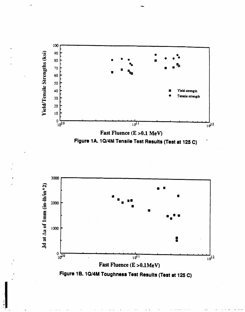
I00J
A
•- 90
' • • @ @"_ 80 • • II
. _ , • 0
' II %_,, 60t,,
50(g
•" 40 mm Yieldsu'enSth
' • Tenm/e su'ength,_ 30mm
'_ 20_J
smm
_., I0
°oO ........ ' ' o2I 1 ' " " ' " 21
Fa_ Fluence(E >0.IMeV}
Figure lA. 1Q/4MTensile Test Results (Test at 125C) "
• 3000 ,
eq< il mm
e_
"_ II mm--_ n' 2000 g
..-
NiM I
,'3
0 ' ' ..... i I s , ......
lo2o _o2_ _o22Fast Fluence (E >O.IMeV)
- Figure 1B.1Q/4M ToughnessTest Results(Test at 126 C)
i

Fig 2 Fast Fluence and DPA in SectorP glna K Re6llOrl
Vertical distance, I_er cent
100 ,' z_ I _ ._o f .2= t ._T I ._' _ .,, , .3, i"1.3 3.2 I 0.6 : 1.3 I 0.9 I 2.7 I 0.6 t 2.7 t;____ ims ,
I ,4o .gT I .41 .50 t .39 _ .7'1' t .31 I .?,/,l,a s.a t 2.= ,., t :s.:n _ o.4I 2.a!g.oa
.02' 1I J1.22i .SO .03 t .50 .97 t 39 i 9T
80_- I : * °, I
8.0, 13 2.1' I S.O t 4.2 12 , 2.8 t 13t
J
.7'I 1.401 .04 ,73 .57 1.1 1 I .48 1.1 1t
6eP
4,,0 .O.l 1li 3.1 0.4 4.9 1• 0.4 1,4
m_
.lt 1 22: .SlD .iii I .SO .97 .30 .976.0 14 2.?' 6.0 4.2 s3 2.ll 13IIII
.4_ 0 .eTl 41 .so al20- i . ._T ,_ ._7
4.8 I 9.| 2.2 4.4 3.3 9.4 2.2 g.Q-- I
" '° "'! "1.3 3.1 0.1 1.2 0.9 2.7 0.6 2.7
.O,lO,i .o, I o, I .o,,.o,,.o, 'OL0"0 -_ , O.O ' - ' 0 0 _-1 ' o_n ' 0.1
o _o 20 30 4o _o so
Distance arouncl tank, degreesFmit fluence ()0.1 MeV) in units of 10 20 r_/cj_2,DPA is too entry in elch I=ox
.....nlr.........,n,,,,_,....... ,,,n,iq[,nn ''1' I" _ ' '' "1............ 'P_IBB....... II " '_ 'I_' ' lr rn' " ,,,' ,'",n, ,_,',l_...._""' "'"'_" "'"",_'lrll"_m,"'_"""r', ,,,....... II,'r,',llTllllllllflI,
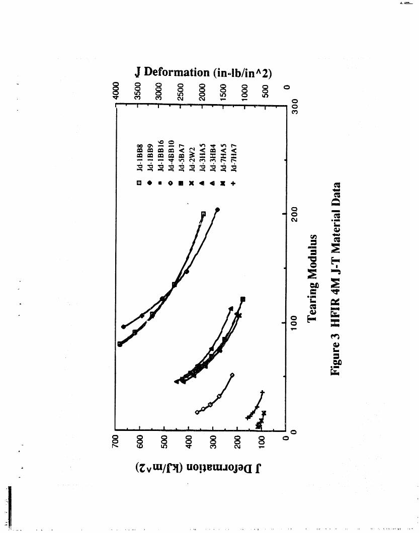
J Deformation (inolb/in ^2)
_ o o o _ §u_ 8 Q
I " I " I " I " I " ! ' I " I ' Q

110,000, ,,,,
M,m ' 0 ,-,_,_._........ 7--- r.A Pm Iqm
Su _._(psi)
6o,om
SO,O00 i ' "I
40,000, i ,,
j I30.000 t !
0 2110'111 4nmlO"_l 6,10'10 IntlO'I| I,I0 II 1.2nlOII '
Fast Neutron Exposure, rt/(cm2) [ -
Figure 4. Yield and Ultimate Strengths of 304 Stainless Steel as a Function ofFast Fluence•
..... " rl_ol II_ I .... II r_llIIr _i r .... iq Ml_r qlll =_
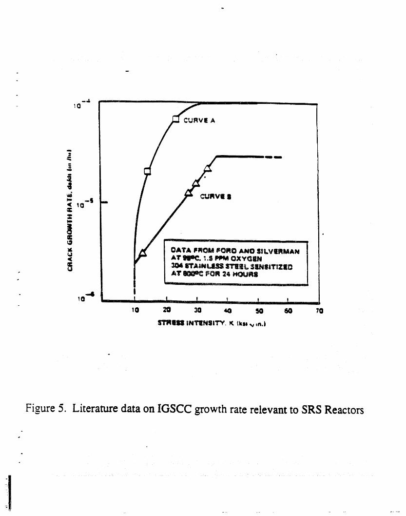
Figure 5. Literature data on IGSCC growth rate relevant to SRS Reactors
I
!1 •

B
Figure 6. Postulated Crack Locations

APPENDIX A.
- SAMPLE CALCULATIONS OF REACTOR TANK ALLOWABLE CRACK LENGTHS
Sample calculations are shown for two postulated through wall cracks Figure A1 shows thelocations of these postulated cracks. Crack A is oriented in the _ial direcuon and crack B is
- circumferentially oriented.
Three steps involved in the calculation are:
1. determine the applied and residual stresses,2. determine the appropriate irradiated condition J-Resistance and J-T
curves, and3. calculate the instability and allowable crack lengths.
Determine the Applied and Residual Stresses
The load states considered in the fracture assessment were: (i) normal operations, (ii) normaloperation + design basis earthquake (DBE) and (iii) accident condition. The last two load statesfall under the faulted or Level D condition def'med by the ASME Boiler and Pressure VesselCode. Since simultaneous occurrence of these two events is highly unlikely, these two faultedevents are considered independent of each other. Nevertheless, calculations for such a case werealso conducted for information. For the axial crack (location A) the accident condition stresses aremore limiting than the normal operation + DBE case. On the other hand, normal operation + DBEcondition stresses are more limiting for the circumferential crack (location B). The loadingsduring both the normal and accident conditions are pressure, thermal gradient and the residualstress.
Based on a review of the technical literature, a self-equilibrated weld residual stress distributionwas assumed. For this distribution, the peak stress magnitude occurs as a tensile stress at both [surfaces of the wall_ and as a compressive stress at rrtid-wa11. For points in between, linear I
t
interpolation is used to get the residual stress (A 5). This distribution applies to the main tank [shell, away from the T-weld and nozzles. Table A I summarizes the applied and weld residual tstress values used in the evaluation.
Determine the Material J.Resistance and J-T Curves (Jmat, Treat)
The J-Resistance curves used in this evaluation were generated by MEA from tests on_-ixr",adiated SRP material. A review of the J-Resistance curve data from all of the specimensirradiated in the HFIR 4M assembly, showed that the specimen H5 exhibited the lowesttoughness. Therefore, the J-Resistance curve data (Figures A2a and A2b) from this specimenwere conservatively used in the fracture evaluation. The J-Integral values in Figure A2a are basedon deformation J (JD) while the values in Figure A2b are based on modified J (JM)" Both thefigures also show the power law fits to the data.
A review of Figure A2a shows that the J-Resistance curve appears to go through as inflectionpoint after which its slope appears to increase with crack extension. The inflection point appearsto be at a JD of ~ 113 kJ/m 2 or 646 in-lb/in 2. Therefore, only the data up to a JD value of 646in-lb/in 2 (the corresponding JM value was 815 in-lb/in 2) were used in determining the material J-Tcurves for instability analysis. Figure A3 shows the JD-T and JM -T curves based on the data inFigures A2a and A2b.
it I II _ .... , II wj ........ _"_ ' _tll[

Page A- 2 EDG.89.48, REVISION IDecember 20, 1989
The expected values of applied tearing modulus, Tai_lied, will be considerably smaller than thelowest tearing modulus values on the material J-T curves shown in Figure A3. Therefore, theextrapolation of these material J-T curves was necessary in order to determine the intersection ofthe material and appli_,,dJ-T curves. Two extrapolation procedures were used as shown in FigureA3. In the first procedure the extrapolation consisted of extending a horizontal straight line fromthe highest JD or JM value. This is the most conservative procedure. A tangent straight line isused in the second proc :dure. This extrapolation procedure is recommended in NLrREG-1061.Although the evaluatiol, ,vas performed using both extrapolation procedures, only the cracklengths based on the first procedure were used in developing the tank flaw acceptance criteria.
Extensive discussion is ongoing among the fracture mechanics specialists on the technical basisfor JM. Therefore, the instability and allowable crack lengths based on the JM -T curve arepresented for information only. The tank flaw acceptance criteria are based on the JD -T curve.
Calculate the Instability and Allowable Crack Lengths
Procedures for the determination of the stress intensity factor, K, or the J-integral, J, for thevarious load cases and the tearing stability evaluation based on elastic-plastic fracture mechanicsare ftrst described. Calculation results for instability and allowable crack lengths are thenpresented.
Calculate the Applied J.Integral for Pressure Loading
This discussion concentrates on the axial flaw. For this case the J-integral can be calculated byusing the formulas for a crack in an mf'mite plate with suitable shell con'ection factor to accountfor the curvature effects (Al, A2). These formulas are summarized below. [
J 1 ,_ y¢_ 2 2
Y ¢_oEo an+l
7t+ (x [3.85 x/__, ( l" I)+ ] ( )n _- oo
For circumferential cracks:
y2 = (1 + 0.3225 ),.2) (0<_<1)
= (0.9 + 0.25 _2) (l<k<5)
For longitudinal cracks:
y2 = 1 + 1.25_.2 (0<_<1)
= (0.6 + 0.9_.)2 (I<_.<5)
a

Page A- 3 EDG-89.48.REVISION 1December 20, 1989
where a = half crack length
• _, = - shell parameter
R = vessel radius
• t = vessel thickness
The materialsu'ess-stminbehaviorwascharacterizedintheRamberg-Osgoodformatasfollows:n
(To)m +(X
I
Ramberg-Osgood Parameters ( A 6): I!
Ct = 4.2
n = 8.9
o o = 90000 psi
% o
£o - -----, E = 28 x 106psiE
Calculate the Applied J.lntegral for Thermal Gradient Loading,i
The stress due to thermal gradient loading is essentially pure bending. Therefore, standard formulasfor calculating K due to a bending stress were used (A3).
Calculate the Applied J.lntegrM for Residual Stress
Due totheself-equilibratednatureoftheresidualstressdistribution,standardsolutionsforstressintensityfactorsintheliteraturecannotbcdJ.rcctlyusedtocalculatetheappliedK. Therefore,rmitcelementanalyseswereusedtodeterminetheK values.Thecorrectsingularityatthecracktipinthefiniteelementmodelswasassuredby usingisoparamctncbrickelementswithquarterpointnodes.
A cylinderrepresentingthetankwasmodeledbytwolayersof20nodebrickelements.Theresidualstress dismbudon was applie.d in the form of nodal loads on the nodes at the crack surface. Thefollowing K values were obtained for two axial cracks analyzed.
CrackLength,2a StressIntensityFactor,K
(inches) ksi"¢"in
3 21• 12 27
1
The peak magnitude of the stress in these analyses is 45 ksi. lt is seen that the calculated K values do" not follow the conventional dependence of K and "¢"a. This is due to the fact that the assumed
- ttuough thickness stress distribution is unusual in the sense that it produces zero net force on the

Page A-4 EDG-89.48-REVISION 1December 20, 1989
crack face. Based on energy considerations, it is logical, to expect that as the through-wall cracklengthens, the stress intensity factor does not continue to increase. The calculated K values areconsistent with this. The K values for other crack lengths were obtained by fitting a curve to thecalculated values. The curve fit function was selected such that as the crack length increases, the Kvalue asymptotically reaches a constant value.
Combine the Applied J.Integral from Various Loadings
Based on the fast fluence level, the vleld strength of the material at both the locations analyzed isexpected to be no greater than 85 ks_ Thus, for the given loadings the material fracture behavior isexpected to be in the linear elasuc fracture mechanics (I.,EFM) regime or at most in the small scaleyielding regime. Therefore, it is reasonable to add the K values from various loadings to obtain aKtota 1. The addition of the individual K values is needed since the J values are nonlinear functions ofstress and are not additive. Since the pressure loading is the only primary loading, a plastic zone sizecorrection was applied to the calculated K values for this case. The Ktota 1 was then converted into an
equivalent Jtotal value by the usual relataonship. J = K2/E.
The calculation sequence is as follows:
(i) Compute the J value due to pressure. Calculate the corresponding Kpressure.
(ii) Compute the K values due to thermal gradient and residual stress using LEFM.
(iii) Determine Ktotal = K pressure ' Kthermal + Kresid.
(iv) Calculate Jtotal = (Ktotal) 2/E"
Tearing Stability Evaluation
The elastic-plastic fracture mechanics based concepts developed by Paris and Hutchinson were usedto determine the instability crack lengths at both the locations_ Figure A4 schematically illustratesthe procedure. The applied J-integral, Japp, (Jtotal in the preceding subsection) was calculated as afunction of crack length for normal and accident condition loads. The appUed :earing modulus,
Tap p, is def'med as,
dJT = E app
app cia002
The intersection of (Japp,Tapp) and the (Jmat, Treat) curve gives the instability point. From theJapp value at instabiUty, the crack length corresponding to instability can be determined. A checkon this approach is available from the J vs a curve analysis iUustratedin Figure 1 of Reference A4.
Safety Factors to Obtain Allowable Crack Lengths
Pressure vessels designed to the ASME Code provide, in general, a safety factor of 3 on pressureagainst failure due to vessel rupture under normal operating conditions. For faulted conditions (orLevel D) the Code provides a safety factor of 1.4 I. For linear elastic fracrure mechanics behavior,assuming linear dependence of K on the square root of the flaw size, the factor of 3 and 1.41 onstress translates to a factor of (32) or close to 10 and (1.412) or close to 2 on the flaw size. SectionXI of the ASME Code allows the user the choice of the safety, factor on stress or the flaw s_ze.
i1 ....

Pao,e A-5 EDG-89.48-REVISI()\ 1v
Decem_r 20. t989
Except for some simple cases the two criteria do not lead to the same allowable flaw s_ze. This tslargely due to the fact that K is not proportional to the square root of the flaw size, but m factdepends on a geometrical magnification factor m addition to the square root term.P
,J
, In this evaluation, safety factors of 3 and 1.41 on applied stress are used for normal and faultedconditions respectively. Thus, the safety factors were only applied to the pressure and seismic
, str'_ses. This is realistic since the objective is to provide safety factors that provide margins onapplied loading. Applying a factor on flaw size ts not meaningful since it uses geomemc factorsthat are not dependent on the current flaw size but on a much larger flaw size that may never occurin future service. Furthermore, a factor on flaw size would apply the same margin on both theresidual stress and the applied stresses. In reality, margins are needed on the apptied loading, noton the as-built stresses m the unloaded condition.
Instability and Allowable Crack Lengths
Figures A5a through A5d show the applied ] and T values as a function of crack length for variousload combinations. The crack length on the applied J-T curve at the intersection with the materialJ-T curve, is the instability crack length. Table A2 shows the instability crack lengths at the twopostulated crack locations.
The results for the accident condition _-DBE case in Table A2 are shown for information only sincethe likelihood of the simultaneous occurrence of these two events is extrg,mely low. The instabilitycrack lengths for the accident condition and the accident condition + DBE at location A are identacalbecause the DBE does not produce any circumferential stress at this locauon. The applied stress(i.e. pressure stress) at location B during normal operation is very low (see Table A 1)and,therefore, instability crack length calculations were not performed for this case.
The allowable crack lengtahswere determined by essentially following the same method as that usedin determining the instability crack lengths. In this case, the pressure and seismic stresses were
• multiplied by the appropriate safety factors. Figures A6a through A6d show the applied J and Tvalues for different !o_ combinations and locations. The allowable crack lengths are shown mTable A3. Allowable crack lengths at location A are smaller than those at location B. The lowest
, allowable crack length at location A is 28 inches. This crack length can be conservatively used indevelopment of tank flaw acceptance criteria.
References
A 1. C.F. Shih and J. W. Hutchinson, Transactions, American Society of Mechanical Engineers,Journal of Engineering Materials and Technology, Series H, Vol. 98, 1976, pp. 289-295.
A2. P.C. Paris and H. Tada, "The Application of Fracture Proof Design Methods Using TearangInstability Theory to Nuclear Piping Postulating Circumferential Through-Wall Cracks," U. S.Nuclear Regulatory Commission Report, NUREG/CR-3464, Washington D.C,, September1983.
A3. D.P. Rook¢ and D. J. Cartwright, "Compendium of Stress Intensity Factors," Her MajestysStationary Office, London, September 1974.
A4. EDG-89.47, "Procedure for Evaluation of Reactor Tank Inspection Results," J. A. Begley et al,May 1989.
I
,, I
A5, SASR#86-64, Fracture Mechanics Evaluation of Potential Flaw Indications in the Savannah i
River L, P and K Tanks," General Elecmc, October 1989. il
A6. SASR # 85-94, GE Design Record File No. 137-0010, December 1985. !" i
il ,r, , I'1' IN ,, , nrl , lr,li, ii ....... q,lr,,,,, rl 4PP4 pill
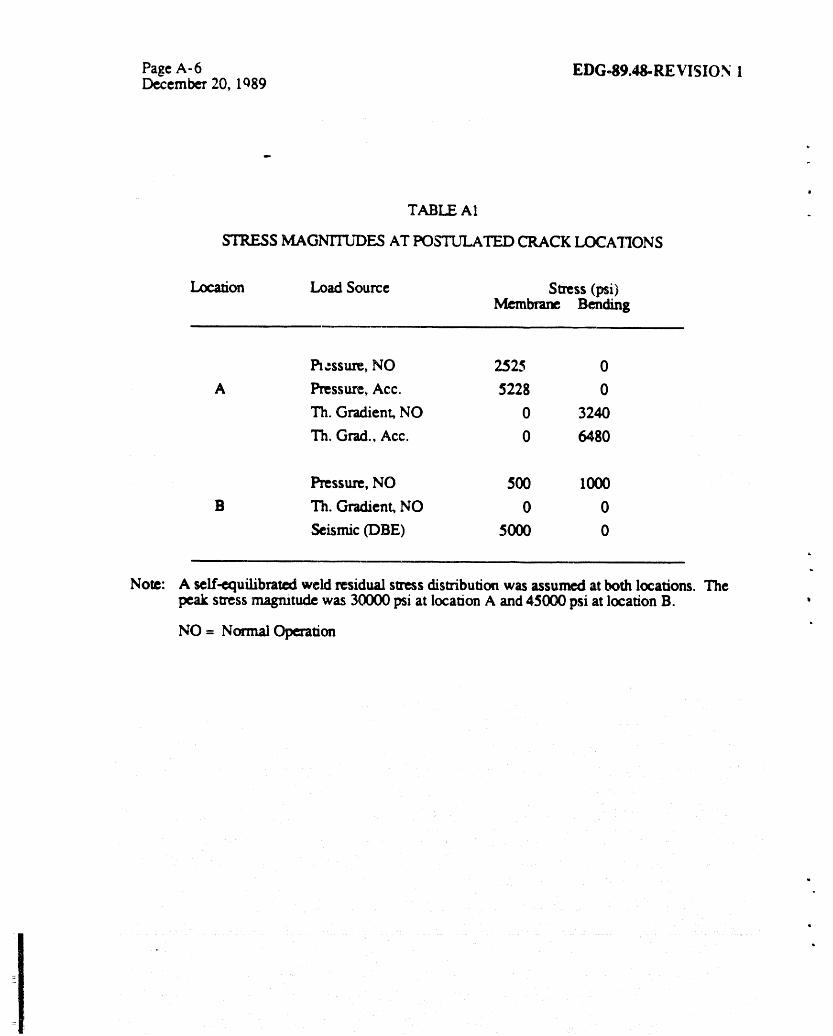
PageA-6 EDG49.,tS-REVISION IDecember 20, 1089
P
o
TABLE Al
STRESS MAGNrI_'DES AT POS'IZYLATEDCRACK LOCATIONS
Ltr,afion Load Source Stress (psi)Membrane Bending
l_,_ssure, NO 2525 0
A Pressure, Acc. 5228 0
Th. Gradient, NO 0 3240
lh.Grad.,Acc. 0 6480
Pressure, NO 500 1000
B lh. Gradient, NO 0 0
Seismic (DBE) 5000 0
Note: A self-equilibrated weld residual stress distribution was assumed at both locations. Thepeakstressmagnitudewas 30000psiatlocationA and45000psiatlocationB.
NO = Normal Operation
w
Q

Page A- 7 EDG-89.48-REVISION 1December 20, 1989
P
TABLE A2
CALCULATED INSTABILITY CRACK LENGTHS
Based on JD Based on JMPostulated Load Horiz. Tang. St Horiz. Tang. StCrack Location Sum) Extrap. Line Extrap. Extrap. Line Extrap.
NO 58 62 65 72
A A_ 32 34 36 4O
Acc + DBE 32 34 36 40
NO _ e Q _ o _ e _ Q _ m _
B NO + DBE 50 :54 56 61
Acc + DBE 46 48 50 5:5
Notes: Ali cracklengths arcininches
NO - Normal Operation
Acc - Accident Cot_fion
DBE- Design Basis Earthquake

Page A-8 EDG-89.48-REVISION 1De_ember 20, 1989
TABLE A3*b
C_TED ALLOWABLE CRACK LENGTHS
Based on JD Based on JM
Postula_:l Load Horiz. Tang. St Horiz. Tang. StCrack Loca_on Sta_ Extrap. Line Extrap. Extrap. Line Extrap.
NO 26 27 29 32
A A_ 25 26 28 31
Acc + DBE 25 26 28 31
NO i _ o m _ o m ,! _ o m D
B NO + DF]E 40 42 44 4"8
Acc + DBE 36 38 40 44 _
Notes: Allcracklengthsareininches
NO- NormalOperationAcc -AccidentCondil_on
DBE -DesignBasis_quake

• B
Figure Al. Postulated Crack Locations

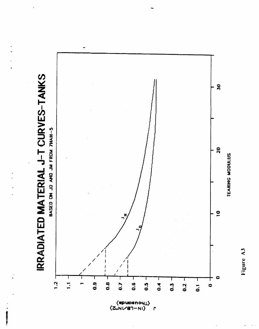
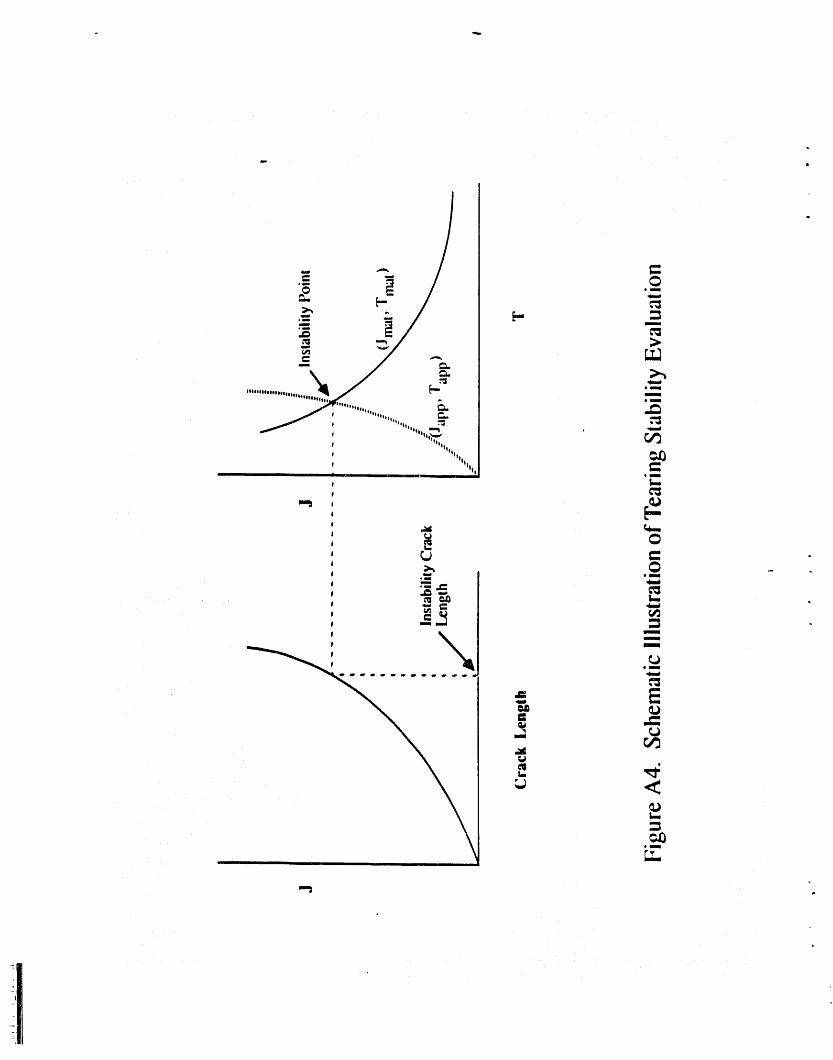
o_ \ '----gsloeoeeeeeeeeoo¢oeose¢oee
_._ ,, .................._',,.'_. r,_
| lllIll
| 'IIIiiI
I II I Ii tlJ emln
_ e_ _ _
_ _ .
.__
',rf.
!1


P •
l--
r !
,_ l I 1 "_P I I°
tD CD / it_I I i,w, f==Z m, ®=o_r_N
_ _ _/,,,_,',_,._ ,,,_ o--I I '_ I I I I I I I I I 1"1 : _ "" _'_'"I I I--r- I I ,'_ 0 -
m • • • • _ ¢ • • • 6 •
(upu©snoq±_
!l (_...INI/I_I--N 1) "IY, O_.I.N, -- p


(:upu©unoq_C_.,NI/en--NI) "_V_O]LLN_- p
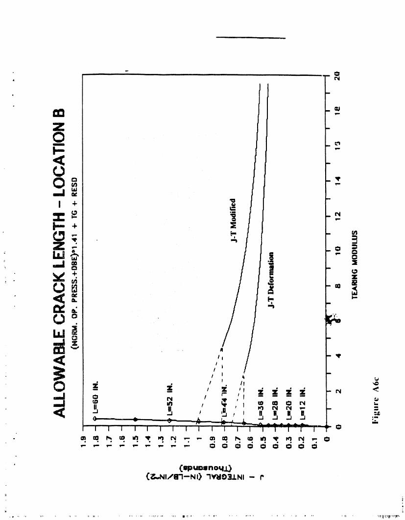
• (_uNnoq.O(_..,.NIfIFI--NI) "INt_IE)21.1.NI".,-P
i
', p,, ' ,_i,,rlql'li'_II_I',_l'li,_'_


J. M. Stone WSRC-RP.89-208-Revision 2Page 6 Task Number 88-001.A.1January 30, 1990
D
W
ATTACHMENT NO. 3

EDG-89.49-REVISION 1D
l
REACTOR TANK UT PROGRAM- SAMPLING PLAN (I._
DECEMBER 1989
Patent Status
This internal management report is beingtransmitted without DOE patent clearance,and no further dissemination or publicationshall be made of the report without priorapprovalof the DOE-SR patent counsel.
Westinghouse Savannah River CompanySavannah River Laboratory
P. O. Box616Aiken, SC 29802
• PREPAREDFORTHEU.S.DEPARTMENTOFENERGYUNDER_CO--CT OE.AC_J_ _._o,R!8_5I=

REACTOR TANK UT PROGRAM -
SAMPLING PLAN iU) ,
P
DOC3JMENT: EDG-89.49-REVISION 1
REVISION 1PREPARED BY:
/_
W. L. DAUGHERTY// DATEWESTINGHOUSE, SRL
REVISION 1
REyIEWED BY:i,
WESTINGHOUSE ' D_T/ _'-- __EI__JSE _ c_/" DATE
J[lV_.MORRISON, R.L. SINDELAR, DATEWJ_STINGHOUSE, RRD WESTINGHOUSE, SRL
This approval page from the original issue of the Reactor Tank UT AcceptanceCriteria by the Tank Acceptance Criteria Working Group is included in Revision 1as a record of the technical expertise behind these acceptance criteria. Revision 1to this document was made to clarify the criteria and not to alter the technicalcontents.
REACTOR TANK UT PROGRAM . SAMPLINGPLAN
i
PREPARED BY..p
..._&,( _D. C. ADAMONIS, _ rDATEWESTINGHOUSE
REVIEWED BY:
N. _WADALLA, SRL DATE H.S. MEHTA, ' DATEGENERAL ELECTRIC COMPANY
N.P. BAUMANN, SRL DATE _.G. MERKLE, DATE
DAT_." S.'RANGANAT_...... DATE-" WESTINGHOUSE GENERAL ELECTRIC COMPANY
S._/BUSH, _ " DATE R.L. SINDELAR, SRLREdVIEW& SYNTHESIS ASSOCIATES
o ,_ :/#_ ( ::. " I ,, '"ii "t 1
G. R. CA_KEY, JR., SRL / - _ DATE J.,-¢.TOBIN ' DATE,/
,<...<.._<,__ ,. /k,'<<..__ ::a_W. E. COOPER DATE S. _V IJ_TETELEDYNE ENGINEERING SF..RVICF.S
. +',,,'...w.L.t_A_GaEa_,Sat. _lm
t

Reyision Summa_ Pa_e
Document No. _ Rev. No. I Issue Date: _ •
Task ID No. 88-001-A-! Effective Date: _ "
Page No. Description of Revision
1 Summary; "bearing ring" corrected to "expansion ring"
2 3rd paragraph;Additional information added to clarify geometric similarity oftanks.
Figure 1 Added "Typical" to caption.
Figures 3-5 Added to revision 1,
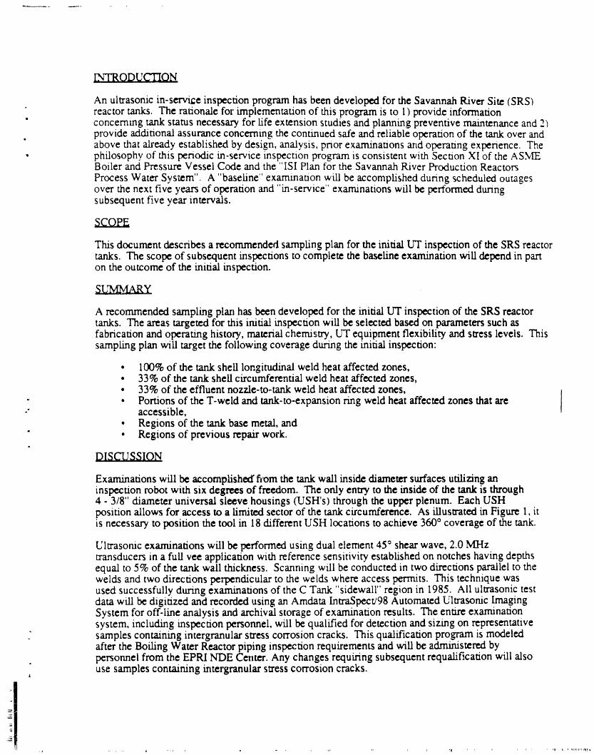
INTRODUCTION
An ultrasomc in-serv_e inspection program has been developed for the Savannah River Site (SRSIreactor tanks. The rationale for implementation of this program is to I ) provide information
' concerning tank status necessary for life extension studies and planning preventive maintenance and 2)• provide additional assurance concerning the continued safe and reliable operation of the tank over and
above that already established by design, analysis, prior examinations and operating experience. The• philosophy of this periodic in-service inspection program is consistent with Section XI of the AS.vIE
Boiler and Pressure Vessel Code and the "ISI Plan for the Savannah River Production ReactorsProcess Water System". A "baseline" exammataon will be accomplished during scheduled outagesover the next five years of operation and "m-service" examinations will be pertormed duringsubsequent five year intervals.
This document describes a recommended sampling plan for the initial I.VI"inspection of the SRS reactortanks. The scope of subsequent inspections to complete the baseline examination will depend in parton the outcome of the initial inspection.
A recommended sampling plan has been developed for the initial LIT inspection of the SRS reactortanks. The areas targeted for this initial inspection will be selected based on parameters such asfabrication and operating history, material chemistry, UT equipment flexibility and stress levels. Thissampling plan will target the following coverage during the initial inspection:
• 100% of the tank shell longitudinal weld heat affected zones,• 33% of the tank shell circumferential weld heat affected zones,• 33% of the effluent nozzle-to-tank weld heat affected zones,
- • Portions of the T-weld and tank-to-expansion ring weld heat affected zones that are-" accessible,
• Regions of the tank base metal, and" • Regions of previous repair work.
DISCUSSION
Examinations will be accomplished fi_omthe tank wall inside diameter surfaces utilizing aninspection robot with six degrees of freedom. The only entry to the inside of the tank is through4 - 3/8" diameter universal sleeve housings (USH's) through the upper plenum. Each USHposition allows for access to a limited sector of the tank circumference. As illustrated in Figure 1, itis necessary to position the tool in 18 different USH locations to achieve 360° coverage of the tank.
Ultrasonic examinations will be performed using dual element 45° shear wave, 2.0 MHztransducers in a full vee application with reference sensitivity established on notches having depthsequal to 5% of the tank wall thickness. Scanning will be conducted in two directions parallel to thewelds and two directions perpendicular to the welds where access permits. This technique wasused successfully during examinations of the C Tank "sidewall" region in 1985. Ali ultrasonic testdata will be digitized and recorded using an Amdata IntraSpectJ98 Automated Ultrasonic ImagingSystem for off-line analysis and archival storage of examination results. The entire examinationsystem, including inspection personnel, will be qualified for detection and sizing on representative
" samples containing intergranular stress corrosion cracks. This qualification program is modeledafter the Boiling Water Reactor piping inspection requirements and will be administered bypersonnel from the EPRI NDE Center. Any changes requiring subsequent requalification will alsouse samples containing intergranular stress corrosion cracks.
L
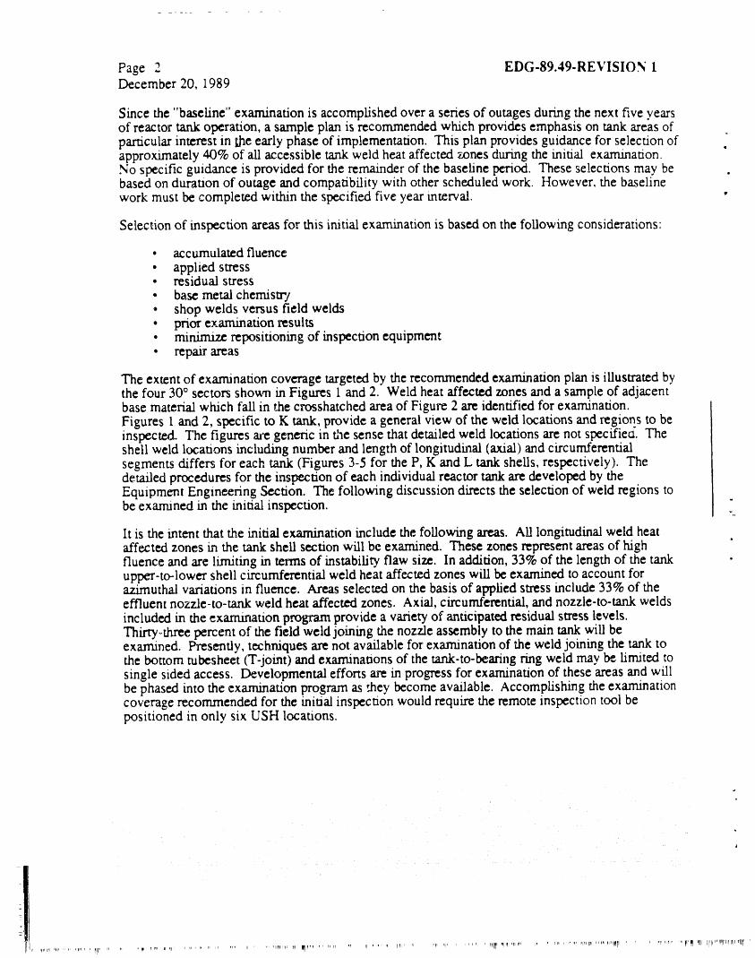
Page 2 EDG-89.49-REVISION 1December 20, 1989
Since the "baseline" examination is accomplished over a series of outages during the next five yearsof reactor tank operation, a sample plan is recommended which provides emphasis on tank areas ofparticular interest in the early phase of implementation. This plan provides guidance for selection ofapproximately 40% of all accessible tank weld heat affected zones during the initial examination.No specific guidance is provided for the remainder of the baseline period. These selections may bebased on duration of outage and compatibility with other scheduled work. However, the baselinework must be completed within the specified five year interval.
Selection of inspection areas for this initial examination is based on the following considerations:
• accumulated fluence• applied stress• residual stress• base metal chemistry• shop welds versus field welds• prior examination results• mimmize repositioning of inspection equipment• repair areas
The extent of examination coverage targeted by the recommended examination plan is illustrated bythe four 30° sectors shown in Figures 1 and 2. Weld heat affected zones and a sample of adjacentbase material which tall in the crosshatched area of Figure 2 are identified for examination.Figures 1 and 2, specific to K tank, provide a general view of the weld locations and regions to beinspected. The figures a_'egeneric in the sense that detailed weld locations are not specified. Theshell weld locataons including number and length of longitudinal (axial) and circumferentialsegments differs for each tank (Figures 3-5 for the P, K and L tank shells, respectively). Thedetailed procedures for the inspection of each individual reactor tank are developed by theEquipment Engineering Section. The following discussion directs the selection of weld regions tobe examined in the initial inspection.
lt is the intent that the initial examination include the following arras. Ali longitudinal weld heat s
affected zones in the tank shell section will be examined. These zones represent areas of highfluence and are limiting in terms of instability flaw size. In addition, 33% of the length of the tankupper-to-lower shell circumferential weld heat affected zones will be examined to account forazimuthal variations in fluence. Areas selected on the basis of applied stress include 33% of theeffluent nozzle-to-tank weld heat affectc-d zones. Axial, circumferential, and nozzle-to-tank weldsincluded in the exam2nation program provide a variety of anticipated residual stress levels.Thirty-three percent of the field weld joining the nozzle assembly to the main tank will beexarn.ined. Presently, techmques are not available for examination of the weld joining the tank tothe bottom tubesheet (T-joint) and examinations of the tank-to-bearing ring weld may be limited tosingle sided access. Developmental efforts are in progress for examination of these areas and willbe phased into the examination program as ,.hey become available. Accomplishing the examinationcoverage recommended for the initial inspection would require the remote inspection tool bepositioned in only six USH locations.
,q,iFirl,al .... i_1_, ,,_![, 1, ,,I'IHFIr nn F_lPm..... , r_ ' "r, _1....... rllll]*ql _I'_' m, t, , ,,,, ,,,r ,qf ,ir,,rrl ,,,_ t_,,tlN_, , r, " PIrai_r "1 IIr_ '111 irl,,,,,rHrl,,,'ltr

Figure I. A '"- ' _t,_ .......... ,. ____: ..... ..., ,_o
ii ,vi., view ,,, ,,,,=, _,.t,.,, ,a,,,, _,,u,,,,,g ,:i.,,,-,,, ,.,,s inspection quadrant
_th it_ ¢orr_nding examination range.


t _
FIGURE 3. MAIN TANK SHELL "P"

FIGURE 4. MAIN TANK SHELL "K"
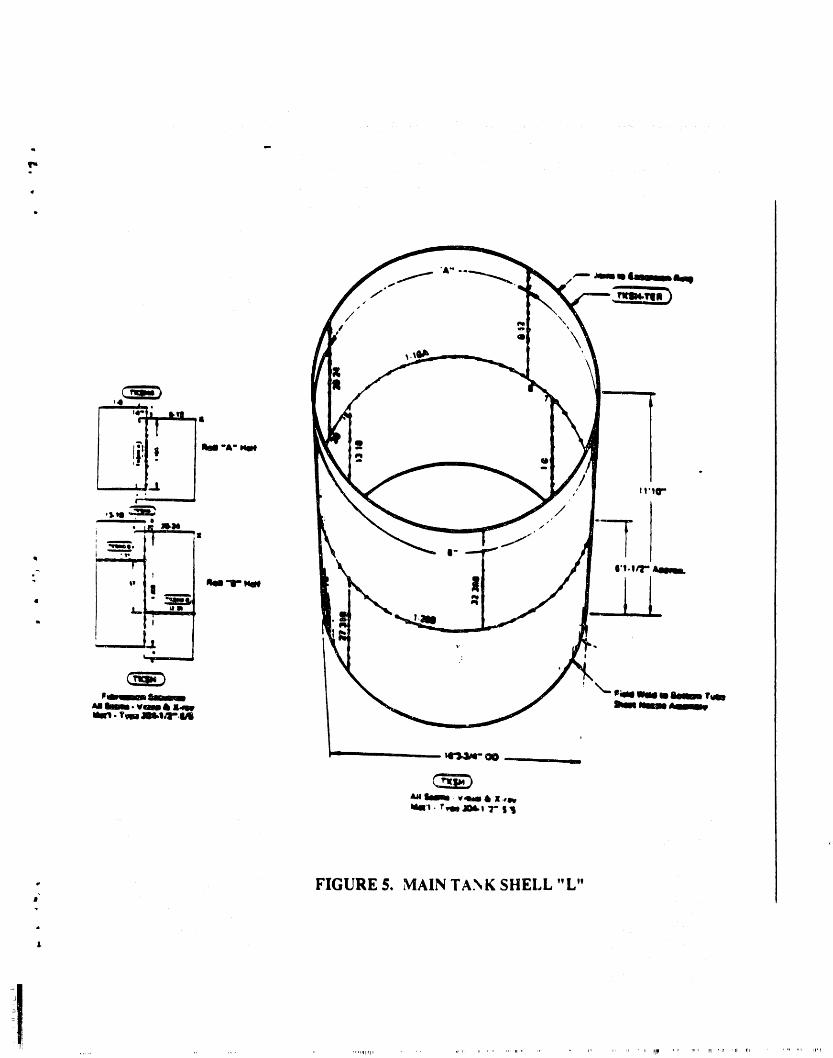
- FIGURE $. MAIN TANK SHELL "L"R.i
X

k